EP2527017A2 - Game program, game system, and game processing method - Google Patents
Game program, game system, and game processing method Download PDFInfo
- Publication number
- EP2527017A2 EP2527017A2 EP12152280A EP12152280A EP2527017A2 EP 2527017 A2 EP2527017 A2 EP 2527017A2 EP 12152280 A EP12152280 A EP 12152280A EP 12152280 A EP12152280 A EP 12152280A EP 2527017 A2 EP2527017 A2 EP 2527017A2
- Authority
- EP
- European Patent Office
- Prior art keywords
- game
- input
- image
- display device
- touch panel
- Prior art date
- Legal status (The legal status is an assumption and is not a legal conclusion. Google has not performed a legal analysis and makes no representation as to the accuracy of the status listed.)
- Granted
Links
- 238000003672 processing method Methods 0.000 title claims description 8
- 238000000034 method Methods 0.000 claims description 74
- 230000008569 process Effects 0.000 claims description 66
- 238000012545 processing Methods 0.000 claims description 21
- 230000005540 biological transmission Effects 0.000 claims description 12
- 238000006073 displacement reaction Methods 0.000 claims description 12
- 238000004891 communication Methods 0.000 description 28
- 230000001133 acceleration Effects 0.000 description 19
- 239000003550 marker Substances 0.000 description 15
- 238000007906 compression Methods 0.000 description 9
- 230000010365 information processing Effects 0.000 description 8
- 230000003287 optical effect Effects 0.000 description 8
- 230000008859 change Effects 0.000 description 6
- 238000006243 chemical reaction Methods 0.000 description 5
- 238000010586 diagram Methods 0.000 description 5
- 230000006870 function Effects 0.000 description 5
- 230000006835 compression Effects 0.000 description 4
- 238000003384 imaging method Methods 0.000 description 4
- CZZAPCPWFCGOCC-GHXNOFRVSA-N (5z)-2-amino-5-[[5-(2-nitrophenyl)furan-2-yl]methylidene]-1,3-thiazol-4-one Chemical compound S1C(N)=NC(=O)\C1=C\C1=CC=C(C=2C(=CC=CC=2)[N+]([O-])=O)O1 CZZAPCPWFCGOCC-GHXNOFRVSA-N 0.000 description 3
- 238000004364 calculation method Methods 0.000 description 2
- 230000006837 decompression Effects 0.000 description 2
- 238000005401 electroluminescence Methods 0.000 description 2
- 238000003780 insertion Methods 0.000 description 2
- 230000037431 insertion Effects 0.000 description 2
- 230000009471 action Effects 0.000 description 1
- 230000002411 adverse Effects 0.000 description 1
- 230000003466 anti-cipated effect Effects 0.000 description 1
- 230000006399 behavior Effects 0.000 description 1
- 230000015556 catabolic process Effects 0.000 description 1
- 238000006731 degradation reaction Methods 0.000 description 1
- 230000001934 delay Effects 0.000 description 1
- 238000001514 detection method Methods 0.000 description 1
- 238000005516 engineering process Methods 0.000 description 1
- 230000010354 integration Effects 0.000 description 1
- 239000004973 liquid crystal related substance Substances 0.000 description 1
- 238000012986 modification Methods 0.000 description 1
- 230000004048 modification Effects 0.000 description 1
- 230000004044 response Effects 0.000 description 1
- 239000004065 semiconductor Substances 0.000 description 1
- 230000035807 sensation Effects 0.000 description 1
- 230000005641 tunneling Effects 0.000 description 1
Images


Classifications
-
- A—HUMAN NECESSITIES
- A63—SPORTS; GAMES; AMUSEMENTS
- A63F—CARD, BOARD, OR ROULETTE GAMES; INDOOR GAMES USING SMALL MOVING PLAYING BODIES; VIDEO GAMES; GAMES NOT OTHERWISE PROVIDED FOR
- A63F13/00—Video games, i.e. games using an electronically generated display having two or more dimensions
- A63F13/20—Input arrangements for video game devices
- A63F13/21—Input arrangements for video game devices characterised by their sensors, purposes or types
- A63F13/214—Input arrangements for video game devices characterised by their sensors, purposes or types for locating contacts on a surface, e.g. floor mats or touch pads
- A63F13/2145—Input arrangements for video game devices characterised by their sensors, purposes or types for locating contacts on a surface, e.g. floor mats or touch pads the surface being also a display device, e.g. touch screens
-
- A—HUMAN NECESSITIES
- A63—SPORTS; GAMES; AMUSEMENTS
- A63F—CARD, BOARD, OR ROULETTE GAMES; INDOOR GAMES USING SMALL MOVING PLAYING BODIES; VIDEO GAMES; GAMES NOT OTHERWISE PROVIDED FOR
- A63F13/00—Video games, i.e. games using an electronically generated display having two or more dimensions
- A63F13/25—Output arrangements for video game devices
- A63F13/26—Output arrangements for video game devices having at least one additional display device, e.g. on the game controller or outside a game booth
-
- A—HUMAN NECESSITIES
- A63—SPORTS; GAMES; AMUSEMENTS
- A63F—CARD, BOARD, OR ROULETTE GAMES; INDOOR GAMES USING SMALL MOVING PLAYING BODIES; VIDEO GAMES; GAMES NOT OTHERWISE PROVIDED FOR
- A63F13/00—Video games, i.e. games using an electronically generated display having two or more dimensions
- A63F13/30—Interconnection arrangements between game servers and game devices; Interconnection arrangements between game devices; Interconnection arrangements between game servers
- A63F13/32—Interconnection arrangements between game servers and game devices; Interconnection arrangements between game devices; Interconnection arrangements between game servers using local area network [LAN] connections
- A63F13/323—Interconnection arrangements between game servers and game devices; Interconnection arrangements between game devices; Interconnection arrangements between game servers using local area network [LAN] connections between game devices with different hardware characteristics, e.g. hand-held game devices connectable to game consoles or arcade machines
-
- A—HUMAN NECESSITIES
- A63—SPORTS; GAMES; AMUSEMENTS
- A63F—CARD, BOARD, OR ROULETTE GAMES; INDOOR GAMES USING SMALL MOVING PLAYING BODIES; VIDEO GAMES; GAMES NOT OTHERWISE PROVIDED FOR
- A63F13/00—Video games, i.e. games using an electronically generated display having two or more dimensions
- A63F13/40—Processing input control signals of video game devices, e.g. signals generated by the player or derived from the environment
- A63F13/42—Processing input control signals of video game devices, e.g. signals generated by the player or derived from the environment by mapping the input signals into game commands, e.g. mapping the displacement of a stylus on a touch screen to the steering angle of a virtual vehicle
- A63F13/428—Processing input control signals of video game devices, e.g. signals generated by the player or derived from the environment by mapping the input signals into game commands, e.g. mapping the displacement of a stylus on a touch screen to the steering angle of a virtual vehicle involving motion or position input signals, e.g. signals representing the rotation of an input controller or a player's arm motions sensed by accelerometers or gyroscopes
-
- A—HUMAN NECESSITIES
- A63—SPORTS; GAMES; AMUSEMENTS
- A63F—CARD, BOARD, OR ROULETTE GAMES; INDOOR GAMES USING SMALL MOVING PLAYING BODIES; VIDEO GAMES; GAMES NOT OTHERWISE PROVIDED FOR
- A63F13/00—Video games, i.e. games using an electronically generated display having two or more dimensions
- A63F13/50—Controlling the output signals based on the game progress
-
- A—HUMAN NECESSITIES
- A63—SPORTS; GAMES; AMUSEMENTS
- A63F—CARD, BOARD, OR ROULETTE GAMES; INDOOR GAMES USING SMALL MOVING PLAYING BODIES; VIDEO GAMES; GAMES NOT OTHERWISE PROVIDED FOR
- A63F13/00—Video games, i.e. games using an electronically generated display having two or more dimensions
- A63F13/55—Controlling game characters or game objects based on the game progress
-
- A—HUMAN NECESSITIES
- A63—SPORTS; GAMES; AMUSEMENTS
- A63F—CARD, BOARD, OR ROULETTE GAMES; INDOOR GAMES USING SMALL MOVING PLAYING BODIES; VIDEO GAMES; GAMES NOT OTHERWISE PROVIDED FOR
- A63F13/00—Video games, i.e. games using an electronically generated display having two or more dimensions
- A63F13/60—Generating or modifying game content before or while executing the game program, e.g. authoring tools specially adapted for game development or game-integrated level editor
- A63F13/63—Generating or modifying game content before or while executing the game program, e.g. authoring tools specially adapted for game development or game-integrated level editor by the player, e.g. authoring using a level editor
-
- A—HUMAN NECESSITIES
- A63—SPORTS; GAMES; AMUSEMENTS
- A63F—CARD, BOARD, OR ROULETTE GAMES; INDOOR GAMES USING SMALL MOVING PLAYING BODIES; VIDEO GAMES; GAMES NOT OTHERWISE PROVIDED FOR
- A63F13/00—Video games, i.e. games using an electronically generated display having two or more dimensions
- A63F13/80—Special adaptations for executing a specific game genre or game mode
- A63F13/843—Special adaptations for executing a specific game genre or game mode involving concurrently two or more players on the same game device, e.g. requiring the use of a plurality of controllers or of a specific view of game data for each player
-
- A—HUMAN NECESSITIES
- A63—SPORTS; GAMES; AMUSEMENTS
- A63F—CARD, BOARD, OR ROULETTE GAMES; INDOOR GAMES USING SMALL MOVING PLAYING BODIES; VIDEO GAMES; GAMES NOT OTHERWISE PROVIDED FOR
- A63F13/00—Video games, i.e. games using an electronically generated display having two or more dimensions
- A63F13/85—Providing additional services to players
- A63F13/86—Watching games played by other players
-
- A—HUMAN NECESSITIES
- A63—SPORTS; GAMES; AMUSEMENTS
- A63F—CARD, BOARD, OR ROULETTE GAMES; INDOOR GAMES USING SMALL MOVING PLAYING BODIES; VIDEO GAMES; GAMES NOT OTHERWISE PROVIDED FOR
- A63F13/00—Video games, i.e. games using an electronically generated display having two or more dimensions
- A63F13/20—Input arrangements for video game devices
- A63F13/21—Input arrangements for video game devices characterised by their sensors, purposes or types
- A63F13/211—Input arrangements for video game devices characterised by their sensors, purposes or types using inertial sensors, e.g. accelerometers or gyroscopes
-
- A—HUMAN NECESSITIES
- A63—SPORTS; GAMES; AMUSEMENTS
- A63F—CARD, BOARD, OR ROULETTE GAMES; INDOOR GAMES USING SMALL MOVING PLAYING BODIES; VIDEO GAMES; GAMES NOT OTHERWISE PROVIDED FOR
- A63F13/00—Video games, i.e. games using an electronically generated display having two or more dimensions
- A63F13/50—Controlling the output signals based on the game progress
- A63F13/53—Controlling the output signals based on the game progress involving additional visual information provided to the game scene, e.g. by overlay to simulate a head-up display [HUD] or displaying a laser sight in a shooting game
- A63F13/533—Controlling the output signals based on the game progress involving additional visual information provided to the game scene, e.g. by overlay to simulate a head-up display [HUD] or displaying a laser sight in a shooting game for prompting the player, e.g. by displaying a game menu
-
- A—HUMAN NECESSITIES
- A63—SPORTS; GAMES; AMUSEMENTS
- A63F—CARD, BOARD, OR ROULETTE GAMES; INDOOR GAMES USING SMALL MOVING PLAYING BODIES; VIDEO GAMES; GAMES NOT OTHERWISE PROVIDED FOR
- A63F13/00—Video games, i.e. games using an electronically generated display having two or more dimensions
- A63F13/80—Special adaptations for executing a specific game genre or game mode
- A63F13/822—Strategy games; Role-playing games
-
- A—HUMAN NECESSITIES
- A63—SPORTS; GAMES; AMUSEMENTS
- A63F—CARD, BOARD, OR ROULETTE GAMES; INDOOR GAMES USING SMALL MOVING PLAYING BODIES; VIDEO GAMES; GAMES NOT OTHERWISE PROVIDED FOR
- A63F2300/00—Features of games using an electronically generated display having two or more dimensions, e.g. on a television screen, showing representations related to the game
- A63F2300/10—Features of games using an electronically generated display having two or more dimensions, e.g. on a television screen, showing representations related to the game characterized by input arrangements for converting player-generated signals into game device control signals
- A63F2300/105—Features of games using an electronically generated display having two or more dimensions, e.g. on a television screen, showing representations related to the game characterized by input arrangements for converting player-generated signals into game device control signals using inertial sensors, e.g. accelerometers, gyroscopes
-
- A—HUMAN NECESSITIES
- A63—SPORTS; GAMES; AMUSEMENTS
- A63F—CARD, BOARD, OR ROULETTE GAMES; INDOOR GAMES USING SMALL MOVING PLAYING BODIES; VIDEO GAMES; GAMES NOT OTHERWISE PROVIDED FOR
- A63F2300/00—Features of games using an electronically generated display having two or more dimensions, e.g. on a television screen, showing representations related to the game
- A63F2300/10—Features of games using an electronically generated display having two or more dimensions, e.g. on a television screen, showing representations related to the game characterized by input arrangements for converting player-generated signals into game device control signals
- A63F2300/1068—Features of games using an electronically generated display having two or more dimensions, e.g. on a television screen, showing representations related to the game characterized by input arrangements for converting player-generated signals into game device control signals being specially adapted to detect the point of contact of the player on a surface, e.g. floor mat, touch pad
- A63F2300/1075—Features of games using an electronically generated display having two or more dimensions, e.g. on a television screen, showing representations related to the game characterized by input arrangements for converting player-generated signals into game device control signals being specially adapted to detect the point of contact of the player on a surface, e.g. floor mat, touch pad using a touch screen
-
- A—HUMAN NECESSITIES
- A63—SPORTS; GAMES; AMUSEMENTS
- A63F—CARD, BOARD, OR ROULETTE GAMES; INDOOR GAMES USING SMALL MOVING PLAYING BODIES; VIDEO GAMES; GAMES NOT OTHERWISE PROVIDED FOR
- A63F2300/00—Features of games using an electronically generated display having two or more dimensions, e.g. on a television screen, showing representations related to the game
- A63F2300/30—Features of games using an electronically generated display having two or more dimensions, e.g. on a television screen, showing representations related to the game characterized by output arrangements for receiving control signals generated by the game device
- A63F2300/301—Features of games using an electronically generated display having two or more dimensions, e.g. on a television screen, showing representations related to the game characterized by output arrangements for receiving control signals generated by the game device using an additional display connected to the game console, e.g. on the controller
-
- A—HUMAN NECESSITIES
- A63—SPORTS; GAMES; AMUSEMENTS
- A63F—CARD, BOARD, OR ROULETTE GAMES; INDOOR GAMES USING SMALL MOVING PLAYING BODIES; VIDEO GAMES; GAMES NOT OTHERWISE PROVIDED FOR
- A63F2300/00—Features of games using an electronically generated display having two or more dimensions, e.g. on a television screen, showing representations related to the game
- A63F2300/30—Features of games using an electronically generated display having two or more dimensions, e.g. on a television screen, showing representations related to the game characterized by output arrangements for receiving control signals generated by the game device
- A63F2300/303—Features of games using an electronically generated display having two or more dimensions, e.g. on a television screen, showing representations related to the game characterized by output arrangements for receiving control signals generated by the game device for displaying additional data, e.g. simulating a Head Up Display
- A63F2300/305—Features of games using an electronically generated display having two or more dimensions, e.g. on a television screen, showing representations related to the game characterized by output arrangements for receiving control signals generated by the game device for displaying additional data, e.g. simulating a Head Up Display for providing a graphical or textual hint to the player
-
- A—HUMAN NECESSITIES
- A63—SPORTS; GAMES; AMUSEMENTS
- A63F—CARD, BOARD, OR ROULETTE GAMES; INDOOR GAMES USING SMALL MOVING PLAYING BODIES; VIDEO GAMES; GAMES NOT OTHERWISE PROVIDED FOR
- A63F2300/00—Features of games using an electronically generated display having two or more dimensions, e.g. on a television screen, showing representations related to the game
- A63F2300/60—Methods for processing data by generating or executing the game program
- A63F2300/6009—Methods for processing data by generating or executing the game program for importing or creating game content, e.g. authoring tools during game development, adapting content to different platforms, use of a scripting language to create content
- A63F2300/6018—Methods for processing data by generating or executing the game program for importing or creating game content, e.g. authoring tools during game development, adapting content to different platforms, use of a scripting language to create content where the game content is authored by the player, e.g. level editor or by game device at runtime, e.g. level is created from music data on CD
-
- A—HUMAN NECESSITIES
- A63—SPORTS; GAMES; AMUSEMENTS
- A63F—CARD, BOARD, OR ROULETTE GAMES; INDOOR GAMES USING SMALL MOVING PLAYING BODIES; VIDEO GAMES; GAMES NOT OTHERWISE PROVIDED FOR
- A63F2300/00—Features of games using an electronically generated display having two or more dimensions, e.g. on a television screen, showing representations related to the game
- A63F2300/80—Features of games using an electronically generated display having two or more dimensions, e.g. on a television screen, showing representations related to the game specially adapted for executing a specific type of game
- A63F2300/8088—Features of games using an electronically generated display having two or more dimensions, e.g. on a television screen, showing representations related to the game specially adapted for executing a specific type of game involving concurrently several players in a non-networked game, e.g. on the same game console
Definitions
- the present invention relates to a game program, a game system, and a game processing method; and, in particular, relates to a game program, a game system, and a game processing method enabling a plurality of players to play the same game together.
- Non-Patent Literature 1 SuperMario Galaxy operation manual," Nintendo Co., Ltd., November 1, 2007, p. 8-9 .
- Non-Patent Literature 1 the main player and the sub player each had to conduct operations (for the main player, controlling a player character; and for the sub player, operation to assist the main player) while watching the same screen.
- An objective of the present invention is to provide a new game program, game system, and game processing method enabling a plurality of players to play the same game together.
- a first configurational example is a game program executed by a computer of a game apparatus for conducting a game process in accordance with an input from a portable display device including a touch panel and an input from at least one input device.
- the game program causes the computer to function as first input reception means, second input reception means, game processing means, image generation means, first display control means, and second display control means.
- the first input reception means is for receiving an input from the touch panel.
- the second input reception means is for receiving an input from the at least one input device.
- the game processing means is for conducting a predetermined game process based on an input received by the first input reception means from the touch panel and an input received by the second input reception means from the at least one input device.
- the image generation means is for generating a first game image and a second game image of an identical game world in accordance with a game process result obtained by the game processing means.
- the first display control means is for outputting the first game image generated by the image generation means to the portable display device.
- the second display control means is for outputting the second game image generated by the image generation means to a display device that is different from the portable display device.
- the game processing means generates a predetermined event at a position in the game world corresponding to a position on the second game image instructed through the touch panel.
- the predetermined event may include an event that assists progress of the game conducted based on an input from the at least one input device.
- the predetermined event may include an event that obstructs progress of the game conducted based on an input from the at least one input device.
- the game processing means may move a predetermined object within the game world based on an input from the at least one input device.
- the game world may be absent of any objects that are moved based on an input from the portable display device.
- the game progressed by the game process may be a game whose objective is achievable without an input from the portable display device.
- an input from the at least one input device may have direct influence on an outcome of the game progressed by the game process
- an input from the portable display device may lack any direct influence on the outcome of the game progressed by the game process
- first game image and the second game image may be substantially identical game images.
- display modes of a specific object in the game world may be different in the first game image and the second game image.
- a display mode of the specific object in the first game image may be a display mode that is more advantageous for a player than a display mode of the specific object in the second game image.
- first game image and the second game image may be game images showing an identical range of the identical game world.
- first game image and the second game image may be game images of the game world from an identical direction.
- the image generation means may generate the second game image so as to scroll in accordance with scrolling of the first game image.
- the first display control means may output the first game image to the portable display device through wireless transmission.
- the first display control means may compress and output the first game image to the portable display device.
- an input section that is different from the touch panel may be provided on the portable display device. Furthermore, in addition to an input from the touch panel, the first input reception means may receive an input also from the input section.
- the game program may cause the computer to further function as displacement amount determination means for determining an amount of displacement based on a signal from the portable display device.
- the image generation means may change, in accordance with the amount of displacement determined by the displacement amount determination means, a relative position of a range of the game world displayed in the first game image with respect to a range of the game world displayed in the second game image.
- the displacement amount determination means may detect a movement of the portable display device based on a signal from the portable display device, and may determine the amount of displacement in accordance with the movement of the portable display device.
- a second configurational example is a game system for conducting a game process in accordance with an input from a portable display device including a touch panel and an input from at least one input device.
- the game system includes first input reception means, second input reception means, game processing means, image generation means, first display control means, and second display control means.
- a third configurational example is a game processing method for conducting a game process in accordance with an input from a portable display device including a touch panel and an input from at least one input device.
- the game processing method includes a first input reception step, a second input reception step, a game processing step, an image generation step, a first display control step, and a second display control step.
- an input is received from the touch panel.
- an input is received from the at least one input device.
- a predetermined game process is conducted based on the input received at the first input reception step from the touch panel and the input received at the second input reception step from the at least one input device.
- a first game image and a second game image of an identical game world are generated in accordance with a game process result obtained at the game processing step.
- the first display control step the first game image generated at the image generation step is outputted to the portable display device.
- the second game image generated at the image generation step is outputted to a display device that is different from the portable display device.
- a predetermined event is generated at a position in the game world corresponding to a position on the second game image instructed through the touch panel.
- a new game program, game system, and game processing method enabling a plurality of players to play the same game together can be provided.
- FIG. 1 A game system according to one embodiment of the present invention will be described with reference to FIG. 1 .
- a game system 1 includes a household television receiver (hereinafter, referred to as a monitor) 2 which is an example of display means, and a stationary game apparatus 3 connected to the monitor 2 via a connection cord.
- the monitor 2 includes loudspeakers 2a.
- the game apparatus 3 includes an optical disc 4, a game apparatus body 5, a terminal device 6, and controllers 7a, 7b, 7c, and 7d (hereinafter, described simply as a controller 7 when there is no particular need to distinguish these as the controllers 7a, 7b, 7c, and 7d).
- the optical disc 4 has stored therein an information processing program (typically, a game program) to be executed by the game apparatus body 5.
- an information processing program typically, a game program
- the monitor 2 displays a game image outputted from the game apparatus body 5.
- the monitor 2 includes the loudspeakers 2a, and each of the loudspeakers 2a outputs a game sound outputted from the game apparatus body 5.
- the game apparatus body 5 executes a game process or the like based on a game program stored in the optical disc 4.
- a plurality of operation sections are provided on the controller 7.
- the controller 7 transmits, to the game apparatus body 5, operation data (controller operation data) representing input states (whether or not each of the operation buttons has been held down) of the operation sections by using, for example, Bluetooth (registered trademark) technology.
- the controller 7 includes an imaging section for taking images of a marker 8 having two LED modules (hereinafter, referred to as "markers") 8L and 8R disposed in the vicinity (in the upper side of the screen in FIG. 1 ) of the display screen of the monitor 2, and an imaging information calculation section for calculating positions of the markers within an image taken by the imaging section.
- the positions of the markers calculated by the imaging information calculation section are transmitted to the game apparatus body 5 as marker coordinate data.
- the movement, position, attitude, and the like can be calculated by the controller 7 based on the marker coordinate data.
- the controller 7 is provided with an acceleration sensor and a gyro sensor. Acceleration data representing acceleration detected by the acceleration sensor and angular velocity data representing angular velocity detected by the gyro sensor are transmitted to the game apparatus body 5. In the game apparatus body 5, directions, movements, and behaviors of the controller 7 can be calculated based on the acceleration data and/or the angular velocity data.
- the terminal device 6 is a portable device that is small enough to be held by a user, and the user is allowed to move the terminal device 6 with hands, or place the terminal device 6 at any location.
- the terminal device 6 includes an LCD (Liquid Crystal Display) 61 as display means, and input means (a touch panel 62, a gyro sensor 604, and the like described later).
- the terminal device 6 and the game apparatus body 5 are communicable with each other wirelessly or via a cable.
- the terminal device 6 receives, from the game apparatus body 5, data of an image (e.g., a game image) generated in the game apparatus body 5, and displays the image represented by the data on an LCD 61.
- an image e.g., a game image
- the terminal device 6 may include any other display device, such as a display device utilizing EL (Electro Luminescence), for example. Further, the terminal device 6 transmits, to the game apparatus body 5, operation data representing the content of an operation performed on the terminal device 6.
- EL Electro Luminescence
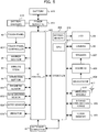
- FIG. 2 is a block diagram illustrating an example of an internal structure of the game apparatus body 5.
- the game apparatus body 5 includes a CPU (Central Processing Unit) 10, a system LSI (Large Scale Integration) 11, an external main memory 12, a ROM/RTC (Read Only Memory/Real Time Clock) 13, a disc drive 14, an AV-IC (Audio Video-Integrated Circuit) 15 and the like.
- CPU Central Processing Unit
- LSI Large Scale Integration
- ROM/RTC Read Only Memory/Real Time Clock
- disc drive 14 an AV-IC (Audio Video-Integrated Circuit) 15 and the like.
- the external main memory 12, the ROM/RTC 13, the disc drive 14, and the AV-IC 15 are connected to the system LSI 11.
- the external main memory 12, which is a volatile memory, is used as a work region and a buffer region for the CPU 10.
- the ROM/RTC 13 includes a ROM (so-called boot ROM) incorporating a program for booting the game apparatus body 5, and a clock circuit (RTC) for counting time.
- the disc drive 14 reads, from the optical disc 4, program data, texture data and the like, and writes the read data into an internal main memory 35 described below or the external main memory 12.
- the system LSI 11 includes an input/output processor (I/O processor) 31, a GPU (Graphics Processor Unit) 32, a DSP (Digital Signal Processor) 33, a VRAM (Video RAM) 34, and the internal main memory 35.
- I/O processor input/output processor
- GPU Graphics Processor Unit
- DSP Digital Signal Processor
- VRAM Video RAM
- the GPU 32 generates an image in accordance with a graphics command (draw command) supplied from the CPU 10.
- the game apparatus body 5 may generate both a game image to be displayed on the monitor 2 and a game image to be displayed on the terminal device 6.
- the game image to be displayed on the monitor 2 may be referred to as a "monitor game image”
- the game image to be displayed on the terminal device 6 may be referred to as a "terminal game image.”
- the DSP 33 serving as an audio processor, generates sound data by using sound data and sound waveform (tone quality) data stored in the internal main memory 35 and the external main memory 12.
- sound data and sound waveform tone quality
- both a game sound to be outputted from the loudspeakers 2a of the monitor 2 and a game sound to be outputted from the loudspeakers of the terminal device 6 may be generated.
- the game sound to be outputted from the monitor 2 may be referred to as a "monitor game sound”
- the game sound to be outputted from the terminal device 6 may be referred to as a "terminal game sound.”
- the image data and sound data generated by the game apparatus body 5 are read by the AV-IC 15.
- the AV-IC 15 outputs the read image data to the monitor 2 and outputs the read sound data to the loudspeakers 2a included in the monitor 2. Thereby, an image is displayed on the monitor 2, and sounds are outputted from the loudspeakers 2a.
- the image data and sound data generated by the game apparatus body 5 are transmitted to the terminal device 6 by the I/O processor 31 or the like. Data transmission to the terminal device 6 by the I/O processor 31 or the like will be described later.
- the I/O processor 31 executes data reception and transmission with the components connected thereto, and download of data from an external apparatus.
- the I/O processor 31 is connected to a flash memory 17, a network communication module 18, a controller communication module 19, an extension connector 20, a memory card connector 21, and a codec LSI 27.
- the codec LSI 27 is connected to a terminal communication module 28.
- the game apparatus body 5 is connected to a network such as the Internet so as to communicate with external information processing apparatuses (for example, other game apparatuses or various servers). That is, the I/O processor 31 is connected to a network via the network communication module 18 and the antenna 22 so as to communicate with external information processing apparatuses connected to the network.
- the flash memory 17 may store not only the data transmitted and received between the game apparatus body 5 and the external information processing apparatuses, but also saved data (result data or progress data of the process) of the game played with the game apparatus body 5. Further, the flash memory 17 may store programs such as a game program.
- the game apparatus body 5 can receive operation data from the controller 7. That is, the I/O processor 31 receives, via the antenna 23 and the controller communication module 19, operation data or the like transmitted from the controller 7, and stores (temporarily) the data in a buffer region of the internal main memory 35 or the external main memory 12.
- the game apparatus body 5 is capable of transmitting/receiving image data, sound data and the like to/from the terminal device 6.
- the I/O processor 31 outputs data of a game image (terminal game image) generated by the GPU 32 to the codec LSI 27.
- the codec LSI 27 performs a predetermined compression process on the image data supplied from the I/O processor 31.
- the terminal communication module 28 performs wireless communication with the terminal device 6. Accordingly, the image data compressed by the codec LSI 27 is transmitted by the terminal communication module 28 to the terminal device 6 via an antenna 29.
- image data transmitted from the game apparatus body 5 to the terminal device 6 is used for a game, and if there is any delay in displaying an image, there can be adverse influence on the operability of the game.
- the codec LSI 27 compresses the image data by using a highly efficient compression technique, for example, the H.264 standard.
- the codec LSI 27 may adopt other compression techniques.
- the terminal communication module 28 is, for example, a Wi-Fi certified communication module.
- the terminal communication module 28 may perform wireless communication with the terminal device 6 at a high speed by using, for example, the technique of MIMO (Multiple Input Multiple Output) adopted in the IEEE802.11n standard, or may use other communication techniques.
- MIMO Multiple Input Multiple Output
- the game apparatus body 5 transmits, to the terminal device 6, sound data as well as the image data. That is, the I/O processor 31 outputs sound data (terminal game sound) generated by the DSP 33 to the terminal communication module 28 via the codec LSI 27.
- the codec LSI 27 performs a compression process on the sound data in a manner similar to that for the image data. Any compression technique may be adopted for the sound data, and a technique that enables a high compression rate and has less sound degradation is preferable. In another embodiment, uncompressed sound data may be transmitted.
- the terminal communication module 28 transmits the compressed image data and sound data to the terminal device 6 via the antenna 29.
- the game apparatus body 5 transmits, in addition to the image data and sound data, various control data to the terminal device 6, according to need.
- the control data represent control instructions for the components included in the terminal device 6, such as an instruction to control on/off of a marker section (a marker section 65 shown in FIG. 5 ), and an instruction to control image taking of a camera (a camera 66 shown in FIG. 5 ).
- the I/O processor 31 transmits the control data to the terminal device 6 in response to an instruction from the CPU 10.
- the game apparatus body 5 can receive various data from the terminal device 6. Although details will be described later, in the exemplary embodiment, the terminal device 6 transmits operation data, image data, and sound data.
- the respective data transmitted from the terminal device 6 are received by the terminal communication module 28 via the antenna 29.
- the image data and sound data transmitted from the terminal device 6 have been subjected to a compression process similar to that for the image data and sound data transmitted from the game apparatus body 5 to the terminal device 6. Accordingly, these image data and sound data are transmitted from the terminal communication module 28 to the codec LSI 27, and subjected to a decompression process by the codec LSI 27.
- the decompressed data are outputted to the I/O processor 31.
- the operation data, which has been received by the terminal communication module 28, is outputted to the I/O processor 31 via the codec LSI 27.
- the I/O processor 31 stores (temporarily) the data received from the terminal device 6 in the buffer region of the internal main memory 35 or the external main memory 12.
- the game apparatus body 5 is connectable to other devices and external storage media via the extension connector 20 and the memory card connector 21.
- the game apparatus body 5 includes (on the front main surface thereof, for example) a power button 24, a reset button 25, an insertion slot through which the optical disc 4 is inserted, an eject button 26 for ejecting the optical disc 4 from the insertion slot of the game apparatus body 5, and the like.
- some of the components of the game apparatus body 5 may be constituted as an extension device separated from the game apparatus body 5.
- the extension device may be connected to the game apparatus body 5 via the extension connector 20, for example.
- the extension device may include, for example, the codec LSI 27, the terminal communication module 28, and the antenna 29, and may be detachably connected to the extension connector 20.
- the game apparatus body can be made communicable with the terminal device 6.
- FIG. 3 is a diagram illustrating an example of an external structure of the terminal device 6. More specifically, (a) of FIG. 3 is a front view, (b) of FIG. 3 is a top view, (c) of FIG. 3 is a right side view, and (d) of FIG. 3 is a bottom view of the terminal device 6.
- FIG. 4 shows an example of a state in which a user holds the terminal device 6 with both hands.
- the terminal device 6 includes a housing 60 which generally has a horizontally long plate-like rectangular shape.
- the housing 60 is small enough to be held by the user.
- the terminal device 6 includes the LCD 61 on a front surface of the housing 60.
- the LCD 61 is provided near the center of the front surface of the housing 60. Therefore, as shown in FIG. 4 , the user, holding the housing 60 at portions to the right and left of the LCD 61, is allowed to move the terminal device 6 while viewing a screen of the LCD 61.
- the terminal device 6 includes, as operation means, a touch panel 62 on the screen of the LCD 61.
- the touch panel 62 is, but is not limited to, a resistive film type touch panel, and a touch panel of any type, such as electrostatic capacitance type, may be used.
- the touch panel 62 may be of single touch type or multiple touch type.
- the touch panel 62 has the same resolution (detection accuracy) as that of the LCD 61. However, the resolution of the touch panel 62 and the resolution of the LCD 61 need not be the same. Since the terminal device 6 has the touch panel 62, the user is allowed to operate the touch panel 62 while moving the terminal device 6. That is, the user is allowed to directly (by using the touch panel 62) perform an input onto the screen of the LCD 61 while moving the LCD 61.
- the terminal device 6 has, as operation means, two analog sticks 63A and 63B, and a plurality of operation buttons 64A to 64L.
- the analog sticks 63A and 63B are each a device for designating a direction.
- the analog sticks 63A and 63B are each configured such that a stick part thereof to be operated by a finger of the user is slidable or tiltable in any direction (at any angle in any direction such as the upward, the downward, the rightward, the leftward, or the diagonal direction) with respect to the front surface of the housing 60.
- the respective operation buttons 64A to 64L are assigned functions, according to need, in accordance with a game program.
- the cross button 64A and the operation buttons 64E to 64H may be used for direction designation operation, selection operation, and the like; and the operation buttons 64B to 64E may be used for determination operation, cancellation operation, and the like.
- the terminal device 6 includes a marker section (the marker section 65 shown in FIG. 5 ) including a marker 65A and a marker 65B, on the front surface of the housing 60.
- the markers 65A and 65B are each constituted by one or more infrared LEDs.
- the marker section 65 is used, like the marker 8, for causing the game apparatus body 5 to calculate a movement or the like of the controller 7 with respect to the marker section 65.
- the game apparatus body 5 is capable of controlling the infrared LEDs of the marker section 65 to be turned on or off.
- the terminal device 6 includes the camera 66.
- the camera 66 is disposed on the surface of the housing 60. Accordingly, the camera 66 is capable of taking an image of the face of the user holding the terminal device 6. For example, the camera 66 can take an image of the user who is playing a game while viewing the LCD 61.
- the terminal device 6 has a microphone (a microphone 609 shown in FIG. 5 ) as sound input means.
- the microphone 609 is embedded in the housing 60 at a position inside the microphone hole 60b.
- the microphone 609 detects for a sound, such as user's voice, around the terminal device 6.
- the terminal device 6 has loudspeakers (loudspeakers 607 shown in FIG. 5 ). Sound from the loudspeakers 607 is outputted from loudspeaker holes 60a provided on the lower side surface of the housing 60.
- the terminal device 6 includes an extension connector 67 for connecting other devices to the terminal device 6.
- the shapes of the operation buttons and the housing 60, the number of the respective components, and the positions in which the components are provided are merely examples.
- the shapes, numbers, and positions may be different from those described above.
- FIG. 5 is a block diagram illustrating an example of an internal structure of the terminal device 6.
- the terminal device 6 includes, in addition to the components shown in FIG. 3 , a touch panel controller 601, a magnetic sensor 602, an acceleration sensor 603, the gyro sensor 604, a user interface controller (UI controller) 605, a codec LSI 606, loudspeakers 607, a sound IC 608, a microphone 609, a wireless module 610, an antenna 611, an infrared communication module 612, a flash memory 613, a power supply IC 614, a battery 615, and a vibrator 619.
- UI controller user interface controller
- the UI controller 605 is a circuit for controlling data input to various input/output sections and data output from various input/output sections.
- the UI controller 605 is connected to the touch panel controller 601, an analog stick 63 (the analog sticks 63A and 63B), the operation button 64 (the operation buttons 64A to 64L), the marker section 65, the magnetic sensor 602, the acceleration sensor 603, the gyro sensor 604, and the vibrator 619. Further, the UI controller 605 is connected to the codec LSI 606 and the extension connector 67.
- the power supply IC 614 is connected to the UI controller 605, so that power is supplied to the respective components through the UI controller 605.
- the internal battery 615 is connected to the power supply IC 614, so that power is supplied from the battery 615. Further, a battery charger 616 or a cable, which is supplied with power from an external power supply, may be connected to the power supply IC 614 via a connector or the like. In this case, the terminal device 6 can be supplied with power and charged from the external power supply by using the battery charger 616 or the cable.
- the touch panel controller 601 is a circuit which is connected to the touch panel 62 and controls the touch panel 62.
- the touch panel controller 601 generates a predetermined form of touch position data, based on a signal from the touch panel 62, and outputs the touch position data to the UI controller 605.
- the touch position data represents coordinates of a position at which an input is performed on an input surface of the touch panel 62.
- the touch panel controller 601 reads a signal from the touch panel 62 and generates touch position data every predetermined period of time. Further, various control instructions are outputted from the UI controller 605 to the touch panel controller 601.
- the analog stick 63 outputs, to the UI controller 605, stick data representing an amount and direction of the sliding (or tilting) of the stick part.
- the operation button 64 outputs, to the UI controller 605, operation button data representing an input status of each of the operation buttons 64A to 64L (whether or not the operation button is pressed).
- the magnetic sensor 602 detects the magnitude and direction of a magnetic field to detect an orientation. Orientation data representing the detected orientation is outputted to the UI controller 605.
- the UI controller 605 outputs, to the magnetic sensor 602, a control instruction for the magnetic sensor 602.
- the magnetic sensor 602 include: an MI (Magnetic Impedance) sensor, a fluxgate sensor, a Hall sensor, a GMR (Giant Magneto Resistance) sensor, a TMR (Tunneling Magneto Resistance) sensor, and an AMR (Anisotropic Magneto Resistance) sensor.
- MI Magnetic Impedance
- GMR Gaant Magneto Resistance
- TMR Transmission Magneto Resistance
- AMR Adisotropic Magneto Resistance
- the acceleration sensor 603 is provided inside the housing 60.
- the acceleration sensor 603 detects the magnitudes of linear accelerations in all three axial directions (xyz axial directions shown in (a) of FIG. 3 ). Acceleration data representing the detected accelerations is outputted to the UI controller 605.
- the UI controller 605 outputs, to the acceleration sensor 603, a control instruction for the acceleration sensor 603.
- the gyro sensor 604 is provided inside the housing 60.
- the gyro sensor 604 detects the angular velocities around all the three axes (the above-described xyz axes).
- Angular velocity data representing the detected angular velocities is outputted to the UI controller 605.
- the UI controller 605 outputs, to the gyro sensor 604, a control instruction for the gyro sensor 604.
- the vibrator 619 is, for example, a vibration motor or a solenoid, and the terminal device 6 is vibrated by actuating the vibrator 619 in accordance with a control instruction outputted from the UI controller 605 to the vibrator 619.
- the UI controller 605 outputs, to the codec LSI 606, the operation data (hereinafter, referred to as terminal operation data) including the touch position data, the stick data, the operation button data, the orientation data, the acceleration data and the angular velocity data, which have been received from the respective components.
- the operation data hereinafter, referred to as terminal operation data
- terminal operation data including the touch position data, the stick data, the operation button data, the orientation data, the acceleration data and the angular velocity data
- the codec LSI 606 is a circuit for performing a compression process on data to be transmitted to the game apparatus body 5, and a decompression process on data transmitted from the game apparatus body 5.
- the LCD 61, the camera 66, the sound IC 608, the wireless module 610, the flash memory 613, and the infrared communication module 612 are connected to the codec LSI 606.
- the codec LSI 606 includes a CPU 617 and an internal memory 618.
- the terminal device 6 is configured not to perform a game process itself, it is necessary for the terminal device 6 to execute programs that are essential for communication or managing the terminal device 6.
- a program stored in the flash memory 613 is loaded into the internal memory 618 and executed by the CPU 617 when the terminal device 6 is powered on, thereby starting up the terminal device 6.
- a part of the area of the internal memory 618 is used as a VRAM for the LCD 61.
- the camera 66 takes an image in accordance with an instruction from the game apparatus body 5, and outputs data of the taken image to the codec LSI 606.
- the codec LSI 606 outputs, to the camera 66, a control instruction for the camera 66, such as an instruction to take an image.
- the camera 66 is also capable of taking a moving picture. That is, the camera 66 is capable of repeatedly performing image taking, and repeatedly outputting image data to the codec LSI 606.
- the sound IC 608 is a circuit for controlling input of sound data to the microphone 609 and output of sound data from the loudspeakers 607.
- the codec LSI 606 transmits the image data from the camera 66, the sound data from the microphone 609, and the terminal operation data from the UI controller 605 to the game apparatus body 5 via the wireless module 610.
- the codec LSI 606 subjects the image data and the sound data to a compression process similar to that performed by the codec LSI 27.
- the compressed image data and sound data, and the terminal operation data are outputted to the wireless module 610 as transmission data.
- the antenna 611 is connected to the wireless module 610, and the wireless module 610 transmits the transmission data to the game apparatus body 5 through the antenna 611.
- the wireless module 610 has the same function as the terminal communication module 28 of the game apparatus body 5. That is, the wireless module 610 has a function of connecting to a wireless LAN by a method based on, for example, the IEEE802.11n standard.
- the transmission data transmitted from the terminal device 6 to the game apparatus body 5 includes the terminal operation data, the image data, and the sound data. If another device is connected to the terminal device 6 through the extension connector 67, data received from the other device may be included in the transmission data.
- the infrared communication module 612 performs, with another device, infrared communication based on, for example, the IRDA standard.
- the codec LSI 606 may include, in the transmission data, data received by the infrared communication, and transmit the transmission data to the game apparatus body 5, according to need.
- the compressed image data and sound data are transmitted from the game apparatus body 5 to the terminal device 6. These data are received by the codec LSI 606 through the antenna 611 and the wireless module 610.
- the codec LSI 606 decompresses the received image data and sound data.
- the decompressed image data is outputted to the LCD 61, and an image according to the image data is displayed on the LCD 61.
- the decompressed sound data is outputted to the sound IC 608, and a sound based on the sound data is outputted from the loudspeakers 607.
- control data When control data is included in the data received from the game apparatus body 5, the codec LSI 606 and the UI controller 605 provide control instructions for the respective components, according to the control data.
- the control data represents control instructions for the respective components (in the exemplary embodiment, the camera 66, the touch panel controller 601, the marker section 65, the sensors 602 to 604, the vibrator 619, and the infrared communication module 612) included in the terminal device 6.
- the control instructions represented by the control data are considered to be instructions to start and halt (stop) the operations of the above-mentioned components. That is, some components which are not used for a game may be halted to reduce power consumption. In this case, data from the halted components are not included in the transmission data transmitted from the terminal device 6 to the game apparatus body 5.
- An objective of this game for a player is to operate the controller 7 and to control a player character to reach a goal point in a game world (a two dimensional virtual space) as shown in FIG. 6 .
- a player character P1, an enemy character E1, a normal block NB, an item block IB, and the like exist in the game world.
- the player character P1 is a character that is to be controlled by the player.
- the enemy character E1 is controlled by a computer based on a predetermined algorithm.
- a normal block NB can be used as a foothold for the player character P1. By hitting a normal block NB from below, the player character P1 can destroy the normal block NB.
- an item block IB is same as a normal block NB, but is a block that has some kind of item (e.g., an item that allows the player character P1 to be in an invincible state for a predetermined period of time) hidden therein.
- An item hidden in the item block IB emerges when the player character P1 hits the item block IB from below.
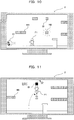
- FIG. 7 shows one example of a monitor game image displayed on the monitor 2 when a certain player (hereinafter, referred to as a player A) is playing the game by using a controller 7a to control the player character P1.
- the main player operates the controller 7 while viewing the monitor game image displayed on the monitor 2.
- FIG. 8 shows a terminal game image displayed on the LCD 61 of the terminal device 6 at the same time when the monitor game image in FIG. 7 is displayed on the monitor 2.
- the sub player operates the terminal device 6 while viewing the terminal game image displayed on the LCD 61.
- FIG. 7 and FIG. 8 are compared, a game image that is substantially identical to the monitor game image viewed by the main player is displayed on the LCD 61. More specifically, an image of the same game world viewed from the same direction is displayed on the monitor game image and the terminal game image, and a display range of the game world displayed in the monitor game image and a display range of the game world displayed in the terminal game image are nearly the same.
- the difference between the monitor game image in FIG. 7 and the terminal game image in FIG. 8 is that an item hidden in an item block IB is not displayed in the monitor game image whereas the item hidden in the item block IB is displayed in the terminal game image.
- the main player does not know which item is hidden in which block until a block is hit from below.
- the sub player knows in advance which item is hidden in which block.
- an arrow HP indicating a hidden passage (a passage that cannot be viewed on the monitor game image) is displayed on the terminal game image.
- the sub player can generate various events at a position corresponding to the touched position in the game world. For example, when nothing exists at the position in the game world corresponding to the touched position, a new normal block NB can be placed at that position. In another embodiment, a block that is different from a normal block NB may be placed. Furthermore, when the enemy character exists at the position in the game world corresponding to the touched position, the movement of the enemy character can be stopped. In addition, when a normal block NB exists at the position in the game world corresponding to the touched position, that normal block NB can be destroyed.
- the sub player can place a new normal block NB by touching a position below the item block IB where there are no other objects as shown in FIG. 9 .
- the normal block NB will also appear in the monitor game image viewed by the main player as shown in FIG. 10 .
- the main player can use that normal block NB as a foothold and have the item hidden in the item block IB appear as shown in FIG. 11 .
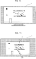
- FIG. 12 shows a monitor game image obtained when the player character P1 has advanced slightly toward the goal point from the state in FIG. 11 .
- the game world displayed in the monitor 2 has been scrolled as a result of the player character P1 advancing toward the goal point.
- FIG. 13 shows a terminal game image displayed on the LCD 61 of the terminal device 6 at the same time point when the monitor game image in FIG. 12 is displayed on the monitor 2.
- an enemy character E2 is approaching the player character P1.
- the sub player touches the enemy character E2 as shown in FIG. 13 , and the movement of the enemy character E2 stops as shown in FIG. 14 .
- the sub player can also obstruct the main player.
- the sub player can obstruct the player character P1 from escaping toward the left direction by placing a new normal block NB at a position show in FIG. 15 .
- the sub player can assist or obstruct the progress of the game played by the main player, by touching a desired position in the game world displayed in the LCD 61 and generating a predetermined event at the touched position.
- the display range of the game world displayed in the terminal game image and the display range of the game world displayed in the monitor game image are basically identical, these display ranges can be shifted from the other.
- the display range of the game world displayed in the terminal game image may be set forward (i.e., in a direction toward the goal point) by a distance Pr from the display range of the game world displayed in the monitor game image.
- displayed on the LCD 61 is a range (as seen in FIG. 18 ) slightly in front of a range (as seen in FIG. 17 ) displayed on the monitor 2, and the sub player can view the game world ahead of the main player and provide assistance such as installing a normal block NB that can be used as a foothold.
- the sub player can change a relative position (i.e., the value of Pr shown in FIG. 16 ) of a display range of the game world displayed in the terminal game image with respect to a display range of the game world displayed in the monitor game image.
- a relative position i.e., the value of Pr shown in FIG. 16
- the relative position of the display range of the game world displayed in the terminal game image shifts in the rightward direction (i.e., the direction toward the goal point)
- the terminal device 6 is moved leftward
- the relative position shifts in the leftward direction (i.e., the direction toward the starting point).
- the movement of the terminal device 6 can be detected by, for example, the acceleration sensor 603.
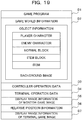
- FIG. 19 shows one example of various data stored in the external main memory 12 of the game apparatus body 5 when the game is executed.
- a game program D1 is a program that causes the CPU 10 of the game apparatus body 5 to execute a game process for achieving the game.
- the game program D1 is loaded, for example, from the optical disc 4 to the external main memory 12.
- Game world information D2 is information that defines the game world.
- the game world information D2 includes, for example, information regarding positions, attitudes, conditions, and the like of various objects (player characters, enemy characters, normal blocks, item blocks, items, and the like) in the game world, information regarding images and the like, and information regarding background images.
- the game world is a two dimensional virtual space, and thereby positions of various objects in the game world are represented by, for example, two-dimensional coordinates of a world coordinate system shown in FIG. 6 .
- Controller operation data D3 is operation data that is periodically transmitted from the controller 7.
- controller operation data from the multiple controllers 7 are stored in the external main memory 12 so as to be distinguishable from each other.
- Terminal operation data D4 is operation data that is periodically transmitted from the terminal device 6. As described above, the terminal operation data D4 includes the touch position data, the acceleration data, and the like.
- Display range information D5 of the monitor game image is information representing a display range of a game world displayed in the monitor game image.
- the display range information D5 of the monitor game image is represented, for example, by an X coordinate value in the world coordinate system shown in FIG. 6 .
- Relative position information D6 is information representing a relative position of a display range of the game world displayed in the terminal game image with respect to a display range of the game world displayed in the monitor game image.
- the relative position information D6 is represented, for example, by a value of Pr shown in FIG. 16 .
- Display range information D7 of the terminal game image is information representing a display range of the game world displayed in the terminal game image.
- the display range information D7 of the terminal game image is represented, for example, by an X coordinate value in the world coordinate system shown in FIG. 6 .
- the CPU 10 sets up initial settings.
- initial settings a process for setting a position of a player character to an initial position, processes for setting, to initial values, the display range information D5 of the monitor game image, the relative position information D6, and the display range information D7 of the terminal game image, and the like are conducted.
- the CPU 10 acquires the terminal operation data D4 from the terminal device 6.
- step S12 the CPU 10 executes an event generating process.
- an event generating process In the following, details of the event generating process will be described with reference to the flowchart in FIG. 21 .
- step S20 the CPU 10 converts the touch position data included in the terminal operation data D4 into world coordinates. The conversion is conducted based on the display range information D7 of the terminal game image. With this, a position in the game world corresponding to a position on the LCD 61 where the sub player has touched is determined.
- the CPU 10 compares the world coordinates obtained through the conversion at step S20 to position information of each object included in the game world information D2, and determines whether the sub player has touched a position in the game world where there are no other objects (i.e., a position absent of various objects such as player characters, enemy characters, normal blocks, and the like). If it is determined that the sub player has touched a position in the game world where there are no other objects, the process advances to step S22; otherwise, the process advances to step S23.
- the CPU 10 arranges a new normal block NB at the position in the game world where the sub player has touched (i.e., the position in the game world indicated by the world coordinates obtained through the conversion at step S20).
- a new normal block NB is added to the game world information D2.
- the CPU 10 compares the world coordinates obtained through the conversion at step S20 to position information of each enemy character included in the game world information D2, and determines whether any of the enemy characters has been touched. If it is determined that the sub player has touched any of the enemy characters, the process advances to step S24; otherwise, the process advances to step S25.
- the CPU 10 stops an enemy character that has been touched by the sub player. More specifically, the information representing the state of the enemy object included in the game world information D2 is changed from a normal state to a stopped state.
- the CPU 10 compares the world coordinates obtained through the conversion at step S20 to position information of each normal block NB included in the game world information D2, and determines whether the sub player has touched any of the normal blocks NB. If it is determined that the sub player has touched any of the normal blocks NB, the process advances to step S26; otherwise, the event generating process ends.
- the CPU 10 destroys a normal block NB that has been touched by the sub player. More specifically, the information representing the normal block NB included in the game world information D2 is deleted. Then the event generating process ends.
- the CPU 10 acquires the controller operation data D3 from the controller 7.
- the CPU 10 controls a player character based on the controller operation data D3. Specifically, information (position, attitude, state) regarding the player character included in the game world information D2 are changed based on the controller operation data D3.
- the CPU 10 controls enemy characters etc., in accordance with a predetermined algorithm. Specifically, information (position, attitude, state) regarding the enemy characters included in the game world information D2 are changed in accordance with the predetermined algorithm.
- the CPU 10 executes a display range update process.
- the display range update process the display range of the game world displayed in the monitor game image and the display range of the game world displayed in the terminal game image are each updated.
- details of the display range update process will be described with reference to the flowchart in FIG. 22 .
- the CPU 10 updates the display range of the game world displayed in the monitor game image based on the current position of the player character. More specifically, the display range information D5 of the monitor game image is updated based on position information of the player character included in the game world information D2. When multiple player characters exist in the game world, the display range information D5 of the monitor game image is updated based on position information of the multiple player characters.
- step S31 the CPU 10 determines whether the terminal device 6 has moved in the rightward direction based on the acceleration data included in the terminal operation data D4. If the terminal device 6 is determined to have moved in the rightward direction, the process advances to step S32; otherwise, the process advances to step S33.
- step S32 the CPU 10 shifts, to the rightward direction (i.e., the direction toward the goal point), the relative position of the display range in the game world displayed in the terminal game image with respect to the display range of the game world displayed in the monitor game image. Specifically, a value of the relative position information D6 is increased in accordance with an amount of movement of the terminal device 6 in the rightward direction. Then, the process advances to step S35.
- the rightward direction i.e., the direction toward the goal point
- step S33 the CPU 10 determines whether the terminal device 6 has moved in the leftward direction based on the acceleration data included in the terminal operation data D4. Then, if the terminal device 6 is determined to have moved in the leftward direction, the process advances to step S34; otherwise, the process advances to step S35.
- step S34 the CPU 10 shifts, to the leftward direction (i.e., the direction toward the starting point), the relative position of the display range in the game world displayed in the terminal game image with respect to the display range of the game world displayed in the monitor game image. Specifically, the value of the relative position information D6 is reduced in accordance with the amount of movement of the terminal device 6 in the leftward direction. Then, the process advances to step S35.
- the CPU 10 updates the display range of the terminal game image based on the relative position information D6 and the display range information D5 of the monitor game image (i.e., updates the display range information D7 of the terminal game image). Then, the display range update process ends.
- step S17 in FIG. 20 the process advances to step S17 in FIG. 20 .
- the CPU 10 generates a monitor game image based on the display range information D5 of the monitor game image and the game world information D2.
- the generated monitor game image is outputted from the game apparatus body 5 to the monitor 2, and displayed on the monitor 2.
- One portion or all of the processes for generating the monitor game image may be conducted on the GPU 32 in accordance with an instruction form the CPU 10.
- the CPU 10 generates a terminal game image based on the display range information D7 of the terminal game image and the game world information D2.
- the generated terminal game image is outputted from the game apparatus body 5 to the terminal device 6, and displayed on the LCD 61 of the terminal device 6.
- One portion or all of the processes for generating the terminal game image may be conducted on the GPU 32 in accordance with an instruction from the CPU 10.
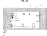
- a specific object may have different display modes in the monitor game image generated at step S17 and in the terminal game image generated at step S18.
- menu icons Ia, Ib, and Ic for the sub player may be displayed only on the terminal game image as shown in FIG. 23 .
- the same game world is displayed on the monitor 2 viewed by the main player and on the LCD 61 viewed by the sub player, and a predetermined event is generated at a position in the game world instructed by the sub player using the touch panel 62. Therefore, the sub player can assist and/or obstruct the main player.
- a screen (the monitor 2) viewed by the main player and a screen (the LCD 61) viewed by the sub player are different, there is no need to display, on the monitor game image, a pointer or a cursor used by the sub player to point a desired position in the game world, and there is no need for the sub player to touch the monitor game image to point a desired position in the game world. Therefore, pointing a desired position in the game world by the sub player can be conducted without disturbing visibility of the monitor game image.
- the desired position can be pointed simply and easily.
- the sub player and the main player can obtain a sensation of playing the same game together.
- the sub player can change the relative position of the display range of the game world displayed in the terminal game image with respect to the display range of the game world displayed in the monitor game image, the sub player can change the relative position as appropriate in order to allow easy operation for himself/herself.
- the sub player can simply and intuitively change the relative position.
- both images of the monitor game image and the terminal game image are generated by the game apparatus body 5 based on the identical game world information D2. Therefore, there is no possibility of any inconsistencies in the two game images; unlike a case where the two game images are individually generated in different information processing apparatuses, such as, for example, when the monitor game image is generated by the game apparatus body 5 and the terminal game image is generated by the terminal device 6.
- the sub player can assist and/or obstruct the main player by using the portable terminal device 6, the sub player can operate the terminal device 6 outside a field of view of the main player. Therefore, the sub player can surprise the main player by generating an event in the game world without being anticipated by the main player beforehand.
- the game world is a two dimensional virtual space in the above described embodiment
- the game world may be a three dimensional virtual space in another embodiment.
- the relative position of the display range of the terminal game image changes with respect to the display range of the monitor game image in accordance with a movement of the terminal device 6 in the rightward or leftward direction in the above described embodiment
- the relative position may change in accordance with any movement (e.g., rotation, and the like) of the terminal device 6.
- the relative position may be changed by the operation button 64 provided on the terminal device 6.
- FIG. 20 to FIG. 22 are executed on a single computer (the CPU 10), in another embodiment, these multiple processes may be distributed and executed on multiple computers. Furthermore, in still another embodiment, one portion of these multiple processes may be achieved through hardware circuitry.
- the multiple processes shown in FIG. 20 to FIG. 22 are executed on a single information processing apparatus (the game apparatus body 5), in another embodiment, these multiple processes may be distributed and executed on multiple information processing apparatuses (e.g., the game apparatus body 5 and a server device).
- the game program D1 is provided to the game apparatus body 5 from the optical disc 4, in another embodiment, the game program D1 may be provided to the game apparatus body 5 from any other computer readable storage media (e.g., CD-ROM, semiconductor memory, and the like). Furthermore, in still another embodiment, the game program D1 may be stored in advance in a nonvolatile memory (the ROM/RTC 13, the flash memory 17) inside the game apparatus body 5. Furthermore, in still another embodiment, the game program D1 may be transmitted to the game apparatus body 5 from another information processing apparatus (game apparatus, server device).
- game apparatus server device
Abstract
Description
- The disclosure of Japanese Patent Application No.
2011-115581, filed on May 24, 2011 - The present invention relates to a game program, a game system, and a game processing method; and, in particular, relates to a game program, a game system, and a game processing method enabling a plurality of players to play the same game together.
- In Non-Patent Literature 1 ("SuperMario Galaxy operation manual," Nintendo Co., Ltd., November 1, 2007, p. 8-9), a game is disclosed in which, while a certain player (main player) is playing the game through controlling of a player character, another player (sub player) can assist the main player.
- In the game disclosed in Non-Patent
Literature 1, the main player and the sub player each had to conduct operations (for the main player, controlling a player character; and for the sub player, operation to assist the main player) while watching the same screen. - An objective of the present invention is to provide a new game program, game system, and game processing method enabling a plurality of players to play the same game together.
- The above described objective is achieved, for example, by the configurations described in the following.
- A first configurational example is a game program executed by a computer of a game apparatus for conducting a game process in accordance with an input from a portable display device including a touch panel and an input from at least one input device. The game program causes the computer to function as first input reception means, second input reception means, game processing means, image generation means, first display control means, and second display control means.
- The first input reception means is for receiving an input from the touch panel. The second input reception means is for receiving an input from the at least one input device. The game processing means is for conducting a predetermined game process based on an input received by the first input reception means from the touch panel and an input received by the second input reception means from the at least one input device. The image generation means is for generating a first game image and a second game image of an identical game world in accordance with a game process result obtained by the game processing means. The first display control means is for outputting the first game image generated by the image generation means to the portable display device. The second display control means is for outputting the second game image generated by the image generation means to a display device that is different from the portable display device. Furthermore, the game processing means generates a predetermined event at a position in the game world corresponding to a position on the second game image instructed through the touch panel.
- The predetermined event may include an event that assists progress of the game conducted based on an input from the at least one input device.
- Furthermore, the predetermined event may include an event that obstructs progress of the game conducted based on an input from the at least one input device.
- Furthermore, the game processing means may move a predetermined object within the game world based on an input from the at least one input device.
- Furthermore, the game world may be absent of any objects that are moved based on an input from the portable display device.
- Furthermore, the game progressed by the game process may be a game whose objective is achievable without an input from the portable display device.
- Furthermore, an input from the at least one input device may have direct influence on an outcome of the game progressed by the game process, and an input from the portable display device may lack any direct influence on the outcome of the game progressed by the game process.
- Furthermore, the first game image and the second game image may be substantially identical game images.
- Furthermore, display modes of a specific object in the game world may be different in the first game image and the second game image.
- Furthermore, a display mode of the specific object in the first game image may be a display mode that is more advantageous for a player than a display mode of the specific object in the second game image.
- Furthermore, the first game image and the second game image may be game images showing an identical range of the identical game world.
- Furthermore, the first game image and the second game image may be game images of the game world from an identical direction.
- Furthermore, the image generation means may generate the second game image so as to scroll in accordance with scrolling of the first game image.
- Furthermore, the first display control means may output the first game image to the portable display device through wireless transmission.
- Furthermore, the first display control means may compress and output the first game image to the portable display device.
- Furthermore, an input section that is different from the touch panel may be provided on the portable display device. Furthermore, in addition to an input from the touch panel, the first input reception means may receive an input also from the input section.
- Furthermore, the game program may cause the computer to further function as displacement amount determination means for determining an amount of displacement based on a signal from the portable display device. Furthermore, the image generation means may change, in accordance with the amount of displacement determined by the displacement amount determination means, a relative position of a range of the game world displayed in the first game image with respect to a range of the game world displayed in the second game image.
- Furthermore, the displacement amount determination means may detect a movement of the portable display device based on a signal from the portable display device, and may determine the amount of displacement in accordance with the movement of the portable display device.
- A second configurational example is a game system for conducting a game process in accordance with an input from a portable display device including a touch panel and an input from at least one input device. The game system includes first input reception means, second input reception means, game processing means, image generation means, first display control means, and second display control means.
- A third configurational example is a game processing method for conducting a game process in accordance with an input from a portable display device including a touch panel and an input from at least one input device. The game processing method includes a first input reception step, a second input reception step, a game processing step, an image generation step, a first display control step, and a second display control step.
- At the first input reception step, an input is received from the touch panel. At the second input reception step, an input is received from the at least one input device. At the game processing step, a predetermined game process is conducted based on the input received at the first input reception step from the touch panel and the input received at the second input reception step from the at least one input device. At the image generation step, a first game image and a second game image of an identical game world are generated in accordance with a game process result obtained at the game processing step. At the first display control step, the first game image generated at the image generation step is outputted to the portable display device. At the second display control step, the second game image generated at the image generation step is outputted to a display device that is different from the portable display device. Furthermore, at the game processing step, a predetermined event is generated at a position in the game world corresponding to a position on the second game image instructed through the touch panel.
- With the present invention, a new game program, game system, and game processing method enabling a plurality of players to play the same game together can be provided.
- These and other objects, features, aspects and advantages of the present invention will become more apparent from the following detailed description of the present invention when taken in conjunction with the accompanying drawings.
-
-
FIG. 1 is a perspective view showing one example of agame system 1 according to one embodiment of the present invention; -
FIG. 2 is a functional block diagram showing one example of agame apparatus body 5 inFIG. 1 ; -
FIG. 3 shows one example of the external configuration of aterminal device 6 inFIG. 1 ; -
FIG. 4 shows one example of a manner in which a user holds theterminal device 6; -
FIG. 5 is a block diagram showing one example of the internal configuration of theterminal device 6 inFIG. 3 ; -
FIG. 6 shows a game world; -
FIG. 7 shows one example of a monitor game image displayed on amonitor 2; -
FIG. 8 shows one example of a terminal game image displayed on anLCD 61; -
FIG. 9 shows one example of the terminal game image displayed on theLCD 61; -
FIG. 10 shows one example of the monitor game image displayed on themonitor 2; -
FIG. 11 shows one example of the monitor game image displayed on themonitor 2; -
FIG. 12 shows one example of the monitor game image displayed on themonitor 2; -
FIG. 13 shows one example of the terminal game image displayed on theLCD 61; -
FIG. 14 shows one example of the monitor game image displayed on themonitor 2; -
FIG. 15 shows one example of the terminal game image displayed on theLCD 61; -
FIG. 16 shows a relative position of a display range of a game world displayed in the terminal game image with respect to a display range of the game world displayed in the monitor game image; -
FIG. 17 shows one example of the monitor game image displayed on themonitor 2; -
FIG. 18 shows one example of the terminal game image displayed on theLCD 61; -
FIG. 19 is a memory map of an externalmain memory 12; -
FIG. 20 is a flowchart showing a flow of a game process based on a game program D1; -
FIG. 21 is a flowchart showing a flow of an event generating process; -
FIG. 22 is a flowchart showing a flow of a display range update process; and -
FIG. 23 shows one example of the terminal game image displayed on theLCD 61. - A game system according to one embodiment of the present invention will be described with reference to
FIG. 1 . - As shown in
FIG. 1 , agame system 1 includes a household television receiver (hereinafter, referred to as a monitor) 2 which is an example of display means, and astationary game apparatus 3 connected to themonitor 2 via a connection cord. Themonitor 2 includesloudspeakers 2a. Furthermore, thegame apparatus 3 includes anoptical disc 4, agame apparatus body 5, aterminal device 6, andcontrollers controller 7 when there is no particular need to distinguish these as thecontrollers - The
optical disc 4 has stored therein an information processing program (typically, a game program) to be executed by thegame apparatus body 5. - The
monitor 2 displays a game image outputted from thegame apparatus body 5. Themonitor 2 includes theloudspeakers 2a, and each of theloudspeakers 2a outputs a game sound outputted from thegame apparatus body 5. - The
game apparatus body 5 executes a game process or the like based on a game program stored in theoptical disc 4. - A plurality of operation sections (operation buttons) are provided on the
controller 7. Thecontroller 7 transmits, to thegame apparatus body 5, operation data (controller operation data) representing input states (whether or not each of the operation buttons has been held down) of the operation sections by using, for example, Bluetooth (registered trademark) technology. - Furthermore, the
controller 7 includes an imaging section for taking images of amarker 8 having two LED modules (hereinafter, referred to as "markers") 8L and 8R disposed in the vicinity (in the upper side of the screen inFIG. 1 ) of the display screen of themonitor 2, and an imaging information calculation section for calculating positions of the markers within an image taken by the imaging section. The positions of the markers calculated by the imaging information calculation section are transmitted to thegame apparatus body 5 as marker coordinate data. In thegame apparatus body 5, the movement, position, attitude, and the like can be calculated by thecontroller 7 based on the marker coordinate data. - Furthermore, the
controller 7 is provided with an acceleration sensor and a gyro sensor. Acceleration data representing acceleration detected by the acceleration sensor and angular velocity data representing angular velocity detected by the gyro sensor are transmitted to thegame apparatus body 5. In thegame apparatus body 5, directions, movements, and behaviors of thecontroller 7 can be calculated based on the acceleration data and/or the angular velocity data. - The
terminal device 6 is a portable device that is small enough to be held by a user, and the user is allowed to move theterminal device 6 with hands, or place theterminal device 6 at any location. Although the specific structure of theterminal device 6 will be described later, theterminal device 6 includes an LCD (Liquid Crystal Display) 61 as display means, and input means (atouch panel 62, agyro sensor 604, and the like described later). Theterminal device 6 and thegame apparatus body 5 are communicable with each other wirelessly or via a cable. Theterminal device 6 receives, from thegame apparatus body 5, data of an image (e.g., a game image) generated in thegame apparatus body 5, and displays the image represented by the data on anLCD 61. Although in the exemplary embodiment, an LCD is used as a display device, theterminal device 6 may include any other display device, such as a display device utilizing EL (Electro Luminescence), for example. Further, theterminal device 6 transmits, to thegame apparatus body 5, operation data representing the content of an operation performed on theterminal device 6. - Next, with reference to
FIG. 2 , an internal structure of thegame apparatus body 5 will be described.FIG. 2 is a block diagram illustrating an example of an internal structure of thegame apparatus body 5. Thegame apparatus body 5 includes a CPU (Central Processing Unit) 10, a system LSI (Large Scale Integration) 11, an externalmain memory 12, a ROM/RTC (Read Only Memory/Real Time Clock) 13, adisc drive 14, an AV-IC (Audio Video-Integrated Circuit) 15 and the like. - In addition to the
CPU 10, the externalmain memory 12, the ROM/RTC 13, thedisc drive 14, and the AV-IC 15 are connected to thesystem LSI 11. The externalmain memory 12, which is a volatile memory, is used as a work region and a buffer region for theCPU 10. The ROM/RTC 13 includes a ROM (so-called boot ROM) incorporating a program for booting thegame apparatus body 5, and a clock circuit (RTC) for counting time. Thedisc drive 14 reads, from theoptical disc 4, program data, texture data and the like, and writes the read data into an internalmain memory 35 described below or the externalmain memory 12. - The
system LSI 11 includes an input/output processor (I/O processor) 31, a GPU (Graphics Processor Unit) 32, a DSP (Digital Signal Processor) 33, a VRAM (Video RAM) 34, and the internalmain memory 35. - The
GPU 32 generates an image in accordance with a graphics command (draw command) supplied from theCPU 10. In the exemplary embodiment, thegame apparatus body 5 may generate both a game image to be displayed on themonitor 2 and a game image to be displayed on theterminal device 6. Hereinafter, the game image to be displayed on themonitor 2 may be referred to as a "monitor game image," and the game image to be displayed on theterminal device 6 may be referred to as a "terminal game image." - The
DSP 33, serving as an audio processor, generates sound data by using sound data and sound waveform (tone quality) data stored in the internalmain memory 35 and the externalmain memory 12. In the exemplary embodiment, similarly to the game images, both a game sound to be outputted from theloudspeakers 2a of themonitor 2 and a game sound to be outputted from the loudspeakers of theterminal device 6 may be generated. Hereinafter, the game sound to be outputted from themonitor 2 may be referred to as a "monitor game sound," and the game sound to be outputted from theterminal device 6 may be referred to as a "terminal game sound." - Among the image data and sound data generated by the
game apparatus body 5, the image data and sound data to be outputted to themonitor 2 are read by the AV-IC 15. Through anAV connector 16, the AV-IC 15 outputs the read image data to themonitor 2 and outputs the read sound data to theloudspeakers 2a included in themonitor 2. Thereby, an image is displayed on themonitor 2, and sounds are outputted from theloudspeakers 2a. - Further, among the image data and sound data generated by the
game apparatus body 5, the image data and sound data to be outputted to theterminal device 6 are transmitted to theterminal device 6 by the I/O processor 31 or the like. Data transmission to theterminal device 6 by the I/O processor 31 or the like will be described later. - The I/
O processor 31 executes data reception and transmission with the components connected thereto, and download of data from an external apparatus. The I/O processor 31 is connected to aflash memory 17, anetwork communication module 18, acontroller communication module 19, anextension connector 20, amemory card connector 21, and acodec LSI 27. Thecodec LSI 27 is connected to aterminal communication module 28. - The
game apparatus body 5 is connected to a network such as the Internet so as to communicate with external information processing apparatuses (for example, other game apparatuses or various servers). That is, the I/O processor 31 is connected to a network via thenetwork communication module 18 and the antenna 22 so as to communicate with external information processing apparatuses connected to the network. Theflash memory 17 may store not only the data transmitted and received between thegame apparatus body 5 and the external information processing apparatuses, but also saved data (result data or progress data of the process) of the game played with thegame apparatus body 5. Further, theflash memory 17 may store programs such as a game program. - The
game apparatus body 5 can receive operation data from thecontroller 7. That is, the I/O processor 31 receives, via theantenna 23 and thecontroller communication module 19, operation data or the like transmitted from thecontroller 7, and stores (temporarily) the data in a buffer region of the internalmain memory 35 or the externalmain memory 12. - The
game apparatus body 5 is capable of transmitting/receiving image data, sound data and the like to/from theterminal device 6. The I/O processor 31 outputs data of a game image (terminal game image) generated by theGPU 32 to thecodec LSI 27. Thecodec LSI 27 performs a predetermined compression process on the image data supplied from the I/O processor 31. Theterminal communication module 28 performs wireless communication with theterminal device 6. Accordingly, the image data compressed by thecodec LSI 27 is transmitted by theterminal communication module 28 to theterminal device 6 via an antenna 29. In the exemplary embodiment, image data transmitted from thegame apparatus body 5 to theterminal device 6 is used for a game, and if there is any delay in displaying an image, there can be adverse influence on the operability of the game. As a result, it is preferable to have no delays with respect to the transmission of image data from thegame apparatus body 5 to theterminal device 6. Therefore, in the exemplary embodiment, thecodec LSI 27 compresses the image data by using a highly efficient compression technique, for example, the H.264 standard. Thecodec LSI 27 may adopt other compression techniques. When the communication rate is sufficiently high, uncompressed image data may be transmitted. Theterminal communication module 28 is, for example, a Wi-Fi certified communication module. Theterminal communication module 28 may perform wireless communication with theterminal device 6 at a high speed by using, for example, the technique of MIMO (Multiple Input Multiple Output) adopted in the IEEE802.11n standard, or may use other communication techniques. - The
game apparatus body 5 transmits, to theterminal device 6, sound data as well as the image data. That is, the I/O processor 31 outputs sound data (terminal game sound) generated by theDSP 33 to theterminal communication module 28 via thecodec LSI 27. Thecodec LSI 27 performs a compression process on the sound data in a manner similar to that for the image data. Any compression technique may be adopted for the sound data, and a technique that enables a high compression rate and has less sound degradation is preferable. In another embodiment, uncompressed sound data may be transmitted. Theterminal communication module 28 transmits the compressed image data and sound data to theterminal device 6 via the antenna 29. - The
game apparatus body 5 transmits, in addition to the image data and sound data, various control data to theterminal device 6, according to need. The control data represent control instructions for the components included in theterminal device 6, such as an instruction to control on/off of a marker section (a marker section 65 shown inFIG. 5 ), and an instruction to control image taking of a camera (acamera 66 shown inFIG. 5 ). The I/O processor 31 transmits the control data to theterminal device 6 in response to an instruction from theCPU 10. - The
game apparatus body 5 can receive various data from theterminal device 6. Although details will be described later, in the exemplary embodiment, theterminal device 6 transmits operation data, image data, and sound data. The respective data transmitted from theterminal device 6 are received by theterminal communication module 28 via the antenna 29. The image data and sound data transmitted from theterminal device 6 have been subjected to a compression process similar to that for the image data and sound data transmitted from thegame apparatus body 5 to theterminal device 6. Accordingly, these image data and sound data are transmitted from theterminal communication module 28 to thecodec LSI 27, and subjected to a decompression process by thecodec LSI 27. The decompressed data are outputted to the I/O processor 31. The operation data, which has been received by theterminal communication module 28, is outputted to the I/O processor 31 via thecodec LSI 27. The I/O processor 31 stores (temporarily) the data received from theterminal device 6 in the buffer region of the internalmain memory 35 or the externalmain memory 12. - The
game apparatus body 5 is connectable to other devices and external storage media via theextension connector 20 and thememory card connector 21. - The
game apparatus body 5 includes (on the front main surface thereof, for example) apower button 24, areset button 25, an insertion slot through which theoptical disc 4 is inserted, aneject button 26 for ejecting theoptical disc 4 from the insertion slot of thegame apparatus body 5, and the like. - In another embodiment, some of the components of the
game apparatus body 5 may be constituted as an extension device separated from thegame apparatus body 5. At this time, the extension device may be connected to thegame apparatus body 5 via theextension connector 20, for example. Specifically, the extension device may include, for example, thecodec LSI 27, theterminal communication module 28, and the antenna 29, and may be detachably connected to theextension connector 20. Thus, by connecting the extension device to the game apparatus body which does not have the above-mentioned, the game apparatus body can be made communicable with theterminal device 6. - Next, a structure of the
terminal device 6 will be described with reference toFIG. 3 to FIG. 5 .FIG. 3 is a diagram illustrating an example of an external structure of theterminal device 6. More specifically, (a) ofFIG. 3 is a front view, (b) ofFIG. 3 is a top view, (c) ofFIG. 3 is a right side view, and (d) ofFIG. 3 is a bottom view of theterminal device 6.FIG. 4 . shows an example of a state in which a user holds theterminal device 6 with both hands. - As shown in
FIG. 3 , theterminal device 6 includes ahousing 60 which generally has a horizontally long plate-like rectangular shape. Thehousing 60 is small enough to be held by the user. - The
terminal device 6 includes theLCD 61 on a front surface of thehousing 60. TheLCD 61 is provided near the center of the front surface of thehousing 60. Therefore, as shown inFIG. 4 , the user, holding thehousing 60 at portions to the right and left of theLCD 61, is allowed to move theterminal device 6 while viewing a screen of theLCD 61. - As shown in (a) of
FIG. 3 , theterminal device 6 includes, as operation means, atouch panel 62 on the screen of theLCD 61. In the exemplary embodiment, thetouch panel 62 is, but is not limited to, a resistive film type touch panel, and a touch panel of any type, such as electrostatic capacitance type, may be used. Thetouch panel 62 may be of single touch type or multiple touch type. In the exemplary embodiment, thetouch panel 62 has the same resolution (detection accuracy) as that of theLCD 61. However, the resolution of thetouch panel 62 and the resolution of theLCD 61 need not be the same. Since theterminal device 6 has thetouch panel 62, the user is allowed to operate thetouch panel 62 while moving theterminal device 6. That is, the user is allowed to directly (by using the touch panel 62) perform an input onto the screen of theLCD 61 while moving theLCD 61. - As shown in
FIG. 3 , theterminal device 6 has, as operation means, twoanalog sticks operation buttons 64A to 64L. The analog sticks 63A and 63B are each a device for designating a direction. The analog sticks 63A and 63B are each configured such that a stick part thereof to be operated by a finger of the user is slidable or tiltable in any direction (at any angle in any direction such as the upward, the downward, the rightward, the leftward, or the diagonal direction) with respect to the front surface of thehousing 60. - The
respective operation buttons 64A to 64L are assigned functions, according to need, in accordance with a game program. For example, thecross button 64A and theoperation buttons 64E to 64H may be used for direction designation operation, selection operation, and the like; and theoperation buttons 64B to 64E may be used for determination operation, cancellation operation, and the like. - As shown in (a) of
FIG. 3 , theterminal device 6 includes a marker section (the marker section 65 shown inFIG. 5 ) including amarker 65A and amarker 65B, on the front surface of thehousing 60. Themarkers marker 8, for causing thegame apparatus body 5 to calculate a movement or the like of thecontroller 7 with respect to the marker section 65. Thegame apparatus body 5 is capable of controlling the infrared LEDs of the marker section 65 to be turned on or off. - The
terminal device 6 includes thecamera 66. Thecamera 66 is disposed on the surface of thehousing 60. Accordingly, thecamera 66 is capable of taking an image of the face of the user holding theterminal device 6. For example, thecamera 66 can take an image of the user who is playing a game while viewing theLCD 61. - The
terminal device 6 has a microphone (amicrophone 609 shown inFIG. 5 ) as sound input means. Themicrophone 609 is embedded in thehousing 60 at a position inside themicrophone hole 60b. Themicrophone 609 detects for a sound, such as user's voice, around theterminal device 6. - The
terminal device 6 has loudspeakers (loudspeakers 607 shown inFIG. 5 ). Sound from theloudspeakers 607 is outputted fromloudspeaker holes 60a provided on the lower side surface of thehousing 60. - The
terminal device 6 includes anextension connector 67 for connecting other devices to theterminal device 6. - In the
terminal device 6 shown inFIG. 3 , the shapes of the operation buttons and thehousing 60, the number of the respective components, and the positions in which the components are provided are merely examples. The shapes, numbers, and positions may be different from those described above. - Next, an internal structure of the
terminal device 6 will be described with reference toFIG. 5. FIG. 5 is a block diagram illustrating an example of an internal structure of theterminal device 6. As shown inFIG. 5 , theterminal device 6 includes, in addition to the components shown inFIG. 3 , atouch panel controller 601, amagnetic sensor 602, anacceleration sensor 603, thegyro sensor 604, a user interface controller (UI controller) 605, acodec LSI 606,loudspeakers 607, asound IC 608, amicrophone 609, awireless module 610, anantenna 611, aninfrared communication module 612, aflash memory 613, apower supply IC 614, abattery 615, and avibrator 619. These electronic components are mounted on an electronic circuit board and accommodated in thehousing 60. - The
UI controller 605 is a circuit for controlling data input to various input/output sections and data output from various input/output sections. TheUI controller 605 is connected to thetouch panel controller 601, an analog stick 63 (the analog sticks 63A and 63B), the operation button 64 (theoperation buttons 64A to 64L), the marker section 65, themagnetic sensor 602, theacceleration sensor 603, thegyro sensor 604, and thevibrator 619. Further, theUI controller 605 is connected to thecodec LSI 606 and theextension connector 67. Thepower supply IC 614 is connected to theUI controller 605, so that power is supplied to the respective components through theUI controller 605. Theinternal battery 615 is connected to thepower supply IC 614, so that power is supplied from thebattery 615. Further, abattery charger 616 or a cable, which is supplied with power from an external power supply, may be connected to thepower supply IC 614 via a connector or the like. In this case, theterminal device 6 can be supplied with power and charged from the external power supply by using thebattery charger 616 or the cable. - The
touch panel controller 601 is a circuit which is connected to thetouch panel 62 and controls thetouch panel 62. Thetouch panel controller 601 generates a predetermined form of touch position data, based on a signal from thetouch panel 62, and outputs the touch position data to theUI controller 605. The touch position data represents coordinates of a position at which an input is performed on an input surface of thetouch panel 62. Thetouch panel controller 601 reads a signal from thetouch panel 62 and generates touch position data every predetermined period of time. Further, various control instructions are outputted from theUI controller 605 to thetouch panel controller 601. - The
analog stick 63 outputs, to theUI controller 605, stick data representing an amount and direction of the sliding (or tilting) of the stick part. The operation button 64 outputs, to theUI controller 605, operation button data representing an input status of each of theoperation buttons 64A to 64L (whether or not the operation button is pressed). - The
magnetic sensor 602 detects the magnitude and direction of a magnetic field to detect an orientation. Orientation data representing the detected orientation is outputted to theUI controller 605. TheUI controller 605 outputs, to themagnetic sensor 602, a control instruction for themagnetic sensor 602. Examples of themagnetic sensor 602 include: an MI (Magnetic Impedance) sensor, a fluxgate sensor, a Hall sensor, a GMR (Giant Magneto Resistance) sensor, a TMR (Tunneling Magneto Resistance) sensor, and an AMR (Anisotropic Magneto Resistance) sensor. However, any sensor may be adopted as long as the sensor can detect an orientation. - The
acceleration sensor 603 is provided inside thehousing 60. Theacceleration sensor 603 detects the magnitudes of linear accelerations in all three axial directions (xyz axial directions shown in (a) ofFIG. 3 ). Acceleration data representing the detected accelerations is outputted to theUI controller 605. TheUI controller 605 outputs, to theacceleration sensor 603, a control instruction for theacceleration sensor 603. - The
gyro sensor 604 is provided inside thehousing 60. Thegyro sensor 604 detects the angular velocities around all the three axes (the above-described xyz axes). Angular velocity data representing the detected angular velocities is outputted to theUI controller 605. TheUI controller 605 outputs, to thegyro sensor 604, a control instruction for thegyro sensor 604. - The
vibrator 619 is, for example, a vibration motor or a solenoid, and theterminal device 6 is vibrated by actuating thevibrator 619 in accordance with a control instruction outputted from theUI controller 605 to thevibrator 619. - The
UI controller 605 outputs, to thecodec LSI 606, the operation data (hereinafter, referred to as terminal operation data) including the touch position data, the stick data, the operation button data, the orientation data, the acceleration data and the angular velocity data, which have been received from the respective components. - The
codec LSI 606 is a circuit for performing a compression process on data to be transmitted to thegame apparatus body 5, and a decompression process on data transmitted from thegame apparatus body 5. TheLCD 61, thecamera 66, thesound IC 608, thewireless module 610, theflash memory 613, and theinfrared communication module 612 are connected to thecodec LSI 606. Thecodec LSI 606 includes aCPU 617 and aninternal memory 618. Although theterminal device 6 is configured not to perform a game process itself, it is necessary for theterminal device 6 to execute programs that are essential for communication or managing theterminal device 6. - For example, a program stored in the
flash memory 613 is loaded into theinternal memory 618 and executed by theCPU 617 when theterminal device 6 is powered on, thereby starting up theterminal device 6. A part of the area of theinternal memory 618 is used as a VRAM for theLCD 61. - The
camera 66 takes an image in accordance with an instruction from thegame apparatus body 5, and outputs data of the taken image to thecodec LSI 606. Thecodec LSI 606 outputs, to thecamera 66, a control instruction for thecamera 66, such as an instruction to take an image. Thecamera 66 is also capable of taking a moving picture. That is, thecamera 66 is capable of repeatedly performing image taking, and repeatedly outputting image data to thecodec LSI 606. - The
sound IC 608 is a circuit for controlling input of sound data to themicrophone 609 and output of sound data from theloudspeakers 607. - The
codec LSI 606 transmits the image data from thecamera 66, the sound data from themicrophone 609, and the terminal operation data from theUI controller 605 to thegame apparatus body 5 via thewireless module 610. In the exemplary embodiment, thecodec LSI 606 subjects the image data and the sound data to a compression process similar to that performed by thecodec LSI 27. The compressed image data and sound data, and the terminal operation data are outputted to thewireless module 610 as transmission data. Theantenna 611 is connected to thewireless module 610, and thewireless module 610 transmits the transmission data to thegame apparatus body 5 through theantenna 611. Thewireless module 610 has the same function as theterminal communication module 28 of thegame apparatus body 5. That is, thewireless module 610 has a function of connecting to a wireless LAN by a method based on, for example, the IEEE802.11n standard. - As described above, the transmission data transmitted from the
terminal device 6 to thegame apparatus body 5 includes the terminal operation data, the image data, and the sound data. If another device is connected to theterminal device 6 through theextension connector 67, data received from the other device may be included in the transmission data. Theinfrared communication module 612 performs, with another device, infrared communication based on, for example, the IRDA standard. Thecodec LSI 606 may include, in the transmission data, data received by the infrared communication, and transmit the transmission data to thegame apparatus body 5, according to need. - As described above, the compressed image data and sound data are transmitted from the
game apparatus body 5 to theterminal device 6. These data are received by thecodec LSI 606 through theantenna 611 and thewireless module 610. Thecodec LSI 606 decompresses the received image data and sound data. The decompressed image data is outputted to theLCD 61, and an image according to the image data is displayed on theLCD 61. On the other hand, the decompressed sound data is outputted to thesound IC 608, and a sound based on the sound data is outputted from theloudspeakers 607. - When control data is included in the data received from the
game apparatus body 5, thecodec LSI 606 and theUI controller 605 provide control instructions for the respective components, according to the control data. As described above, the control data represents control instructions for the respective components (in the exemplary embodiment, thecamera 66, thetouch panel controller 601, the marker section 65, thesensors 602 to 604, thevibrator 619, and the infrared communication module 612) included in theterminal device 6. In the exemplary embodiment, the control instructions represented by the control data are considered to be instructions to start and halt (stop) the operations of the above-mentioned components. That is, some components which are not used for a game may be halted to reduce power consumption. In this case, data from the halted components are not included in the transmission data transmitted from theterminal device 6 to thegame apparatus body 5. - Next, one example of a game executed the game system of the exemplary embodiment will be described with reference to
FIG. 6 to FIG. 18 . - An objective of this game for a player is to operate the
controller 7 and to control a player character to reach a goal point in a game world (a two dimensional virtual space) as shown inFIG. 6 . - As shown in
FIG. 6 , for example, a player character P1, an enemy character E1, a normal block NB, an item block IB, and the like exist in the game world. - The player character P1 is a character that is to be controlled by the player. The enemy character E1 is controlled by a computer based on a predetermined algorithm.
- A normal block NB can be used as a foothold for the player character P1. By hitting a normal block NB from below, the player character P1 can destroy the normal block NB.
- The appearance of an item block IB is same as a normal block NB, but is a block that has some kind of item (e.g., an item that allows the player character P1 to be in an invincible state for a predetermined period of time) hidden therein. An item hidden in the item block IB emerges when the player character P1 hits the item block IB from below.
- In this game, while one or more players (main player(s)) are playing the game by controlling respective player characters by using the
respective controllers 7, another player (sub player) can assist the main player(s) by generating various events in the game world by using theterminal device 6. In the following, an assisting operation by the sub player through a use of theterminal device 6 will be specifically described. -
FIG. 7 shows one example of a monitor game image displayed on themonitor 2 when a certain player (hereinafter, referred to as a player A) is playing the game by using acontroller 7a to control the player character P1. The main player operates thecontroller 7 while viewing the monitor game image displayed on themonitor 2. -
FIG. 8 shows a terminal game image displayed on theLCD 61 of theterminal device 6 at the same time when the monitor game image inFIG. 7 is displayed on themonitor 2. The sub player operates theterminal device 6 while viewing the terminal game image displayed on theLCD 61. - As it is obvious when
FIG. 7 andFIG. 8 are compared, a game image that is substantially identical to the monitor game image viewed by the main player is displayed on theLCD 61. More specifically, an image of the same game world viewed from the same direction is displayed on the monitor game image and the terminal game image, and a display range of the game world displayed in the monitor game image and a display range of the game world displayed in the terminal game image are nearly the same. - The difference between the monitor game image in
FIG. 7 and the terminal game image inFIG. 8 is that an item hidden in an item block IB is not displayed in the monitor game image whereas the item hidden in the item block IB is displayed in the terminal game image. As a result, the main player does not know which item is hidden in which block until a block is hit from below. However, the sub player knows in advance which item is hidden in which block. In addition, an arrow HP indicating a hidden passage (a passage that cannot be viewed on the monitor game image) is displayed on the terminal game image. - By touching the
touch panel 62 of theterminal device 6, the sub player can generate various events at a position corresponding to the touched position in the game world. For example, when nothing exists at the position in the game world corresponding to the touched position, a new normal block NB can be placed at that position. In another embodiment, a block that is different from a normal block NB may be placed. Furthermore, when the enemy character exists at the position in the game world corresponding to the touched position, the movement of the enemy character can be stopped. In addition, when a normal block NB exists at the position in the game world corresponding to the touched position, that normal block NB can be destroyed. - For example, in order to allow the player character P1 to obtain an item hidden in an item block IB, the sub player can place a new normal block NB by touching a position below the item block IB where there are no other objects as shown in
FIG. 9 . When the sub player places a new normal block NB in the game world, the normal block NB will also appear in the monitor game image viewed by the main player as shown inFIG. 10 . As a result, the main player can use that normal block NB as a foothold and have the item hidden in the item block IB appear as shown inFIG. 11 . -
FIG. 12 shows a monitor game image obtained when the player character P1 has advanced slightly toward the goal point from the state inFIG. 11 . As can be understood from the figure, the game world displayed in themonitor 2 has been scrolled as a result of the player character P1 advancing toward the goal point. Furthermore,FIG. 13 shows a terminal game image displayed on theLCD 61 of theterminal device 6 at the same time point when the monitor game image inFIG. 12 is displayed on themonitor 2. - In
FIG. 12 and FIG. 13 an enemy character E2 is approaching the player character P1. Here, in order to assist the main player, the sub player touches the enemy character E2 as shown inFIG. 13 , and the movement of the enemy character E2 stops as shown inFIG. 14 . - Instead of assisting the main player, the sub player can also obstruct the main player. For example, the sub player can obstruct the player character P1 from escaping toward the left direction by placing a new normal block NB at a position show in
FIG. 15 . - In such manner, in this game, the sub player can assist or obstruct the progress of the game played by the main player, by touching a desired position in the game world displayed in the
LCD 61 and generating a predetermined event at the touched position. - As shown in
FIG. 7 to FIG. 15 , although the display range of the game world displayed in the terminal game image and the display range of the game world displayed in the monitor game image are basically identical, these display ranges can be shifted from the other. - For example, as shown in
FIG. 16 , the display range of the game world displayed in the terminal game image may be set forward (i.e., in a direction toward the goal point) by a distance Pr from the display range of the game world displayed in the monitor game image. As a result, displayed on theLCD 61 is a range (as seen inFIG. 18 ) slightly in front of a range (as seen inFIG. 17 ) displayed on themonitor 2, and the sub player can view the game world ahead of the main player and provide assistance such as installing a normal block NB that can be used as a foothold. - In the exemplary embodiment, by moving the
terminal device 6 in the right or left direction, the sub player can change a relative position (i.e., the value of Pr shown inFIG. 16 ) of a display range of the game world displayed in the terminal game image with respect to a display range of the game world displayed in the monitor game image. Specifically, with respect to a display range of the game world displayed in the monitor game image, when theterminal device 6 is moved rightward, the relative position of the display range of the game world displayed in the terminal game image shifts in the rightward direction (i.e., the direction toward the goal point), and when theterminal device 6 is moved leftward, the relative position shifts in the leftward direction (i.e., the direction toward the starting point). The movement of theterminal device 6 can be detected by, for example, theacceleration sensor 603. - Next, detailed action of the game system to achieve the game will be described with reference to
FIG. 19 to FIG. 22 . -
FIG. 19 shows one example of various data stored in the externalmain memory 12 of thegame apparatus body 5 when the game is executed. - A game program D1 is a program that causes the
CPU 10 of thegame apparatus body 5 to execute a game process for achieving the game. The game program D1 is loaded, for example, from theoptical disc 4 to the externalmain memory 12. - Game world information D2 is information that defines the game world. The game world information D2 includes, for example, information regarding positions, attitudes, conditions, and the like of various objects (player characters, enemy characters, normal blocks, item blocks, items, and the like) in the game world, information regarding images and the like, and information regarding background images. In the exemplary embodiment, the game world is a two dimensional virtual space, and thereby positions of various objects in the game world are represented by, for example, two-dimensional coordinates of a world coordinate system shown in
FIG. 6 . - Controller operation data D3 is operation data that is periodically transmitted from the
controller 7. When multiple main players are to simultaneously play the game by usingmultiple controllers 7 among thecontrollers multiple controllers 7 are stored in the externalmain memory 12 so as to be distinguishable from each other. - Terminal operation data D4 is operation data that is periodically transmitted from the
terminal device 6. As described above, the terminal operation data D4 includes the touch position data, the acceleration data, and the like. - Display range information D5 of the monitor game image is information representing a display range of a game world displayed in the monitor game image. The display range information D5 of the monitor game image is represented, for example, by an X coordinate value in the world coordinate system shown in
FIG. 6 . - Relative position information D6 is information representing a relative position of a display range of the game world displayed in the terminal game image with respect to a display range of the game world displayed in the monitor game image. The relative position information D6 is represented, for example, by a value of Pr shown in
FIG. 16 . - Display range information D7 of the terminal game image is information representing a display range of the game world displayed in the terminal game image. The display range information D7 of the terminal game image is represented, for example, by an X coordinate value in the world coordinate system shown in
FIG. 6 . - Next, a flow of the game process executed by the
CPU 10 of thegame apparatus body 5 based on the game program D1 will be described with reference to flowcharts inFIG. 20 to FIG. 22 . - When execution of the game program D1 is initiated, first, at step S10 in
FIG. 20 , theCPU 10 sets up initial settings. In the initial settings, a process for setting a position of a player character to an initial position, processes for setting, to initial values, the display range information D5 of the monitor game image, the relative position information D6, and the display range information D7 of the terminal game image, and the like are conducted. - At step S11, the
CPU 10 acquires the terminal operation data D4 from theterminal device 6. - At step S12, the
CPU 10 executes an event generating process. In the following, details of the event generating process will be described with reference to the flowchart inFIG. 21 . - When the event generating process is initiated, first, at step S20, the
CPU 10 converts the touch position data included in the terminal operation data D4 into world coordinates. The conversion is conducted based on the display range information D7 of the terminal game image. With this, a position in the game world corresponding to a position on theLCD 61 where the sub player has touched is determined. - At step S21, the
CPU 10 compares the world coordinates obtained through the conversion at step S20 to position information of each object included in the game world information D2, and determines whether the sub player has touched a position in the game world where there are no other objects (i.e., a position absent of various objects such as player characters, enemy characters, normal blocks, and the like). If it is determined that the sub player has touched a position in the game world where there are no other objects, the process advances to step S22; otherwise, the process advances to step S23. - At step S22, the
CPU 10 arranges a new normal block NB at the position in the game world where the sub player has touched (i.e., the position in the game world indicated by the world coordinates obtained through the conversion at step S20). Thus, information regarding the new normal block NB is added to the game world information D2. - At step S23, the
CPU 10 compares the world coordinates obtained through the conversion at step S20 to position information of each enemy character included in the game world information D2, and determines whether any of the enemy characters has been touched. If it is determined that the sub player has touched any of the enemy characters, the process advances to step S24; otherwise, the process advances to step S25. - At step S24, the
CPU 10 stops an enemy character that has been touched by the sub player. More specifically, the information representing the state of the enemy object included in the game world information D2 is changed from a normal state to a stopped state. - At step S25, the
CPU 10 compares the world coordinates obtained through the conversion at step S20 to position information of each normal block NB included in the game world information D2, and determines whether the sub player has touched any of the normal blocks NB. If it is determined that the sub player has touched any of the normal blocks NB, the process advances to step S26; otherwise, the event generating process ends. - At step S26, the
CPU 10 destroys a normal block NB that has been touched by the sub player. More specifically, the information representing the normal block NB included in the game world information D2 is deleted. Then the event generating process ends. - When the event generating process ends, the process advances to step S13 in
FIG. 20 . - At step S13, the
CPU 10 acquires the controller operation data D3 from thecontroller 7. - At step S14, the
CPU 10 controls a player character based on the controller operation data D3. Specifically, information (position, attitude, state) regarding the player character included in the game world information D2 are changed based on the controller operation data D3. - At step S15, the
CPU 10 controls enemy characters etc., in accordance with a predetermined algorithm. Specifically, information (position, attitude, state) regarding the enemy characters included in the game world information D2 are changed in accordance with the predetermined algorithm. - At step S16, the
CPU 10 executes a display range update process. In the display range update process, the display range of the game world displayed in the monitor game image and the display range of the game world displayed in the terminal game image are each updated. In the following, details of the display range update process will be described with reference to the flowchart inFIG. 22 . - When the display range update process is initiated, first, at step S30, the
CPU 10 updates the display range of the game world displayed in the monitor game image based on the current position of the player character. More specifically, the display range information D5 of the monitor game image is updated based on position information of the player character included in the game world information D2. When multiple player characters exist in the game world, the display range information D5 of the monitor game image is updated based on position information of the multiple player characters. - At step S31, the
CPU 10 determines whether theterminal device 6 has moved in the rightward direction based on the acceleration data included in the terminal operation data D4. If theterminal device 6 is determined to have moved in the rightward direction, the process advances to step S32; otherwise, the process advances to step S33. - At step S32, the
CPU 10 shifts, to the rightward direction (i.e., the direction toward the goal point), the relative position of the display range in the game world displayed in the terminal game image with respect to the display range of the game world displayed in the monitor game image. Specifically, a value of the relative position information D6 is increased in accordance with an amount of movement of theterminal device 6 in the rightward direction. Then, the process advances to step S35. - At step S33, the
CPU 10 determines whether theterminal device 6 has moved in the leftward direction based on the acceleration data included in the terminal operation data D4. Then, if theterminal device 6 is determined to have moved in the leftward direction, the process advances to step S34; otherwise, the process advances to step S35. - At step S34, the
CPU 10 shifts, to the leftward direction (i.e., the direction toward the starting point), the relative position of the display range in the game world displayed in the terminal game image with respect to the display range of the game world displayed in the monitor game image. Specifically, the value of the relative position information D6 is reduced in accordance with the amount of movement of theterminal device 6 in the leftward direction. Then, the process advances to step S35. - At step S35, the
CPU 10 updates the display range of the terminal game image based on the relative position information D6 and the display range information D5 of the monitor game image (i.e., updates the display range information D7 of the terminal game image). Then, the display range update process ends. - When the display range update process ends, the process advances to step S17 in
FIG. 20 . - At step S17, the
CPU 10 generates a monitor game image based on the display range information D5 of the monitor game image and the game world information D2. The generated monitor game image is outputted from thegame apparatus body 5 to themonitor 2, and displayed on themonitor 2. One portion or all of the processes for generating the monitor game image may be conducted on theGPU 32 in accordance with an instruction form theCPU 10. - At step S18, the
CPU 10 generates a terminal game image based on the display range information D7 of the terminal game image and the game world information D2. The generated terminal game image is outputted from thegame apparatus body 5 to theterminal device 6, and displayed on theLCD 61 of theterminal device 6. One portion or all of the processes for generating the terminal game image may be conducted on theGPU 32 in accordance with an instruction from theCPU 10. - A specific object (e.g., the item block IB shown in
FIG. 7 andFIG. 8 ) may have different display modes in the monitor game image generated at step S17 and in the terminal game image generated at step S18. Furthermore, for example, menu icons Ia, Ib, and Ic for the sub player may be displayed only on the terminal game image as shown inFIG. 23 . - As described above, in the exemplary embodiment, the same game world is displayed on the
monitor 2 viewed by the main player and on theLCD 61 viewed by the sub player, and a predetermined event is generated at a position in the game world instructed by the sub player using thetouch panel 62. Therefore, the sub player can assist and/or obstruct the main player. - Furthermore, in the exemplary embodiment, since a screen (the monitor 2) viewed by the main player and a screen (the LCD 61) viewed by the sub player are different, there is no need to display, on the monitor game image, a pointer or a cursor used by the sub player to point a desired position in the game world, and there is no need for the sub player to touch the monitor game image to point a desired position in the game world. Therefore, pointing a desired position in the game world by the sub player can be conducted without disturbing visibility of the monitor game image.
- Furthermore, in the exemplary embodiment, since pointing a desired position in the game world by the sub player is conducted by using the
touch panel 62, the desired position can be pointed simply and easily. - Furthermore, in the exemplary embodiment, since a substantially identical game image is displayed on the screen (the monitor 2) viewed by the main player and on the screen (the LCD 61) viewed by the sub player, the sub player and the main player can obtain a sensation of playing the same game together.
- Furthermore, in the exemplary embodiment, since scrolling of the terminal game image is conducted automatically in accordance with scrolling of the monitor game image, there is no need for the sub player to manually scroll the terminal game image so as to chase the player character.
- Furthermore, in the exemplary embodiment, since the sub player can change the relative position of the display range of the game world displayed in the terminal game image with respect to the display range of the game world displayed in the monitor game image, the sub player can change the relative position as appropriate in order to allow easy operation for himself/herself.
- Furthermore, since the relative position can be changed by moving the
terminal device 60, the sub player can simply and intuitively change the relative position. - Furthermore, in the exemplary embodiment, both images of the monitor game image and the terminal game image are generated by the
game apparatus body 5 based on the identical game world information D2. Therefore, there is no possibility of any inconsistencies in the two game images; unlike a case where the two game images are individually generated in different information processing apparatuses, such as, for example, when the monitor game image is generated by thegame apparatus body 5 and the terminal game image is generated by theterminal device 6. - Furthermore, in the exemplary embodiment, since the sub player can assist and/or obstruct the main player by using the portable
terminal device 6, the sub player can operate theterminal device 6 outside a field of view of the main player. Therefore, the sub player can surprise the main player by generating an event in the game world without being anticipated by the main player beforehand. - It is to be noted that the above described embodiment is merely one embodiment of the present invention, and does not limit the scope of the present invention in any way.
- For example, although the game world is a two dimensional virtual space in the above described embodiment, the game world may be a three dimensional virtual space in another embodiment.
- Furthermore, although the relative position of the display range of the terminal game image changes with respect to the display range of the monitor game image in accordance with a movement of the
terminal device 6 in the rightward or leftward direction in the above described embodiment, in another embodiment, the relative position may change in accordance with any movement (e.g., rotation, and the like) of theterminal device 6. Furthermore, in still another embodiment, the relative position may be changed by the operation button 64 provided on theterminal device 6. - Furthermore, in the above described embodiment, although the multiple processes shown in
FIG. 20 to FIG. 22 are executed on a single computer (the CPU 10), in another embodiment, these multiple processes may be distributed and executed on multiple computers. Furthermore, in still another embodiment, one portion of these multiple processes may be achieved through hardware circuitry. - Furthermore, in the above described embodiment, although the multiple processes shown in
FIG. 20 to FIG. 22 are executed on a single information processing apparatus (the game apparatus body 5), in another embodiment, these multiple processes may be distributed and executed on multiple information processing apparatuses (e.g., thegame apparatus body 5 and a server device). - Furthermore, in the above described embodiment, although the game program D1 is provided to the
game apparatus body 5 from theoptical disc 4, in another embodiment, the game program D1 may be provided to thegame apparatus body 5 from any other computer readable storage media (e.g., CD-ROM, semiconductor memory, and the like). Furthermore, in still another embodiment, the game program D1 may be stored in advance in a nonvolatile memory (the ROM/RTC 13, the flash memory 17) inside thegame apparatus body 5. Furthermore, in still another embodiment, the game program D1 may be transmitted to thegame apparatus body 5 from another information processing apparatus (game apparatus, server device). - While the invention has been described in detail, the foregoing description is in all aspects illustrative and not restrictive. It will be understood that numerous other modifications and variations can be devised without departing from the scope of the invention.
Claims (20)
- A game program executed by a computer (10) of a game apparatus (5) for conducting a game process in accordance with an input from a portable display device (6) including a touch panel (62) and an input from at least one input device (7), the computer being caused to function as:first input reception means (10, S11) for receiving an input from the touch panel,second input reception means (10, S13) for receiving an input from the at least one input device;game processing means (10, S12, S14) for conducting a predetermined game process based on an input received by the first input reception means from the touch panel and an input received by the second input reception means from the at least one input device;image generation means (10, S17, S18) for generating a first game image and a second game image of an identical game world in accordance with a game process result obtained by the game processing means;first display control means (10, S18) for outputting, to the portable display device, the first game image generated by the image generation means; andsecond display control means (10, S17) for outputting, to a display device (2) that is different from the portable display device, the second game image generated by the image generation means, whereinthe game processing means generates (S12) a predetermined event at a position in the game world corresponding to a position on the second game image instructed through the touch panel.
- The game program according to claim 1, wherein the predetermined event includes an event that assists progress of the game conducted based on an input from the at least one input device.
- The game program according to claim 1 or 2, wherein the predetermined event includes an event that obstructs progress of the game conducted based on an input from the at least one input device.
- The game program according to any one of claims 1 to 3, wherein the game processing means moves a predetermined object within the game world based on an input from the at least one input device.
- The game program according to claim 4, wherein the game world is absent of any objects that are moved based on an input from the portable display device.
- The game program according to claim 4 or 5, wherein the game progressed by the game process is a game whose objective is achievable without an input from the portable display device.
- The game program according to claim 4 or 5, wherein
an input from the at least one input device has direct influence on an outcome of the game progressed by the game process, and
an input from the portable display device lacks any direct influence on the outcome of the game progressed by the game process. - The game program according to any one of claims 1 to 7, wherein the first game image and the second game image are substantially identical game images.
- The game program according to claim 8, wherein display modes of a specific object in the game world are different in the first game image and the second game image.
- The game program according to claim 9, wherein a display mode of the specific object in the first game image is a display mode that is more advantageous for a player than a display mode of the specific object in the second game image.
- The game program according to any one of claims 1 to 7, wherein the first game image and the second game image are game images showing an identical range of the identical game world.
- The game program according to any one of claims 1 to 7, wherein the first game image and the second game image are game images of the game world viewed from an identical direction.
- The game program according to any one of claims 1 to 12, wherein the image generation means generates the second game image so as to scroll in accordance with scrolling of the first game image.
- The game program according to any one of claims 1 to 13, wherein the first display control means outputs the first game image to the portable display device through wireless transmission.
- The game program according to any one of claims 1 to 14, wherein the first display control means compresses and outputs the first game image to the portable display device.
- The game program according to any one of claims 1 to 15, wherein
an input section that is different from the touch panel is provided on the portable display device, and
in addition to an input from the touch panel, the first input reception means receives an input also from the input section. - The game program according to any one of claims 1 to 7, and 12, wherein
the computer is caused to further function as displacement amount determination means for determining an amount of displacement based on a signal from the portable display device, and
the image generation means changes, in accordance with the amount of displacement determined by the displacement amount determination means, a relative position of a range of the game world displayed in the first game image with respect to a range of the game world displayed in the second game image. - The game program according to claim 17, wherein the displacement amount determination means detects a movement of the portable display device based on a signal from the portable display device, and determines the amount of displacement in accordance with the movement of the portable display device.
- A game system (5) for conducting a game process in accordance with an input from a portable display device (6) including a touch panel (62) and an input from at least one input device (7), the game system comprising:first input reception means (10, S11) for receiving an input from the touch panel,second input reception means (10, S13) for receiving an input from the at least one input device;game processing means (10, S12, S14) for conducting a predetermined game process based on an input received by the first input reception means from the touch panel and an input received by the second input reception means from the at least one input device;image generation means (10, S17, S18) for generating a first game image and a second game image of an identical game world in accordance with a game process result obtained by the game processing means;first display control means (10, S18) for outputting, to the portable display device, the first game image generated by the image generation means; andsecond display control means (10, S17) for outputting, to a display device (2) that is different from the portable display device, the second game image generated by the image generation means, whereinthe game processing means generates (S12) a predetermined event at a position in the game world corresponding to a position on the second game image instructed through the touch panel.
- A game processing method for conducting a game process in accordance with an input from a portable display device (6) including a touch panel (62) and an input from at least one input device (7), the method comprising:a first input reception step (S11) of receiving an input from the touch panel;a second input reception step (S13) of receiving an input from the at least one input device;a game processing step (S12, S14) of conducting a predetermined game process based on the input received at the first input reception step from the touch panel and the input received at the second input reception step from the at least one input device;an image generation step (S17, S18) of generating a first game image and a second game image of an identical game world in accordance with a game process result obtained at the game processing step;a first display control step (S18) of outputting, to the portable display device, the first game image generated at the image generation step; anda second display control step (S17) of outputting, to a display device (2) that is different' from the portable display device, the second game image generated at the image generation step, whereinat the game processing step, a predetermined event is generated at a position in the game world corresponding to a position on the second game image instructed through the touch panel.
Applications Claiming Priority (1)
| Application Number | Priority Date | Filing Date | Title |
|---|---|---|---|
| JP2011115581A JP5876229B2 (en) | 2011-05-24 | 2011-05-24 | GAME PROGRAM, GAME DEVICE, GAME SYSTEM, AND GAME PROCESSING METHOD |
Publications (3)
| Publication Number | Publication Date |
|---|---|
| EP2527017A2 true EP2527017A2 (en) | 2012-11-28 |
| EP2527017A3 EP2527017A3 (en) | 2014-06-25 |
| EP2527017B1 EP2527017B1 (en) | 2018-01-03 |
Family
ID=45607588
Family Applications (1)
| Application Number | Title | Priority Date | Filing Date |
|---|---|---|---|
| EP12152280.9A Active EP2527017B1 (en) | 2011-05-24 | 2012-01-24 | Game program, game system, and game processing method |
Country Status (3)
| Country | Link |
|---|---|
| US (3) | US8628391B2 (en) |
| EP (1) | EP2527017B1 (en) |
| JP (1) | JP5876229B2 (en) |
Families Citing this family (13)
| Publication number | Priority date | Publication date | Assignee | Title |
|---|---|---|---|---|
| JP6069636B2 (en) * | 2012-12-27 | 2017-02-01 | 株式会社コナミデジタルエンタテインメント | GAME SYSTEM, CONTROL METHOD AND COMPUTER PROGRAM USED FOR THE SAME |
| JP6216120B2 (en) | 2013-01-22 | 2017-10-18 | 任天堂株式会社 | GAME PROGRAM, GAME DEVICE, GAME SYSTEM, AND GAME PROCESSING METHOD |
| KR20140142863A (en) * | 2013-06-05 | 2014-12-15 | 한국전자통신연구원 | Apparatus and method for providing graphic editors |
| JP6721285B2 (en) | 2013-08-21 | 2020-07-15 | 任天堂株式会社 | Information processing apparatus, information processing system, information processing program, and information processing method |
| CN103706114B (en) * | 2013-11-27 | 2018-05-08 | 北京智明星通科技股份有限公司 | A kind of system and method for operating touch screen game |
| US20170148267A1 (en) * | 2015-11-25 | 2017-05-25 | Joseph William PARKER | Celebrity chase virtual world game system and method |
| WO2018042466A1 (en) * | 2016-08-31 | 2018-03-08 | 任天堂株式会社 | Game program, game processing method, game system, and game device |
| WO2018042467A1 (en) * | 2016-08-31 | 2018-03-08 | 任天堂株式会社 | Game program, game processing method, game system, and game device |
| JP6935439B2 (en) * | 2019-02-01 | 2021-09-15 | 任天堂株式会社 | Information processing program, information processing device, information processing system and information processing method |
| JP7011612B2 (en) * | 2019-02-01 | 2022-01-26 | 任天堂株式会社 | Information processing program, information processing device, information processing system and information processing method |
| US20220152500A1 (en) * | 2019-03-29 | 2022-05-19 | Sony Interactive Entertainment Inc. | Information processing system, control apparatus, medium, control method, and program |
| JP7381898B2 (en) | 2020-07-31 | 2023-11-16 | 株式会社カプコン | Game system and game control method |
| TWI768526B (en) * | 2020-10-30 | 2022-06-21 | 茂達電子股份有限公司 | Three-phase motor driving circuit and method |
Family Cites Families (14)
| Publication number | Priority date | Publication date | Assignee | Title |
|---|---|---|---|---|
| JPH06285259A (en) * | 1993-03-31 | 1994-10-11 | Sega Enterp Ltd | Liquid crystal controller |
| JPH08173633A (en) * | 1994-12-27 | 1996-07-09 | Sharp Corp | Game system |
| JP2000116940A (en) * | 1998-10-15 | 2000-04-25 | Seta Corp | Bidirectional communication-type game system |
| JP2000157719A (en) * | 1998-11-26 | 2000-06-13 | Namco Ltd | Information storage medium and game apparatus |
| JP2001034247A (en) * | 1999-07-19 | 2001-02-09 | Minolta Co Ltd | Video display device |
| US6375572B1 (en) | 1999-10-04 | 2002-04-23 | Nintendo Co., Ltd. | Portable game apparatus with acceleration sensor and information storage medium storing a game progam |
| US6966837B1 (en) * | 2001-05-10 | 2005-11-22 | Best Robert M | Linked portable and video game systems |
| JP3690672B2 (en) * | 2002-05-17 | 2005-08-31 | 任天堂株式会社 | Game system and game program |
| JP3841413B2 (en) * | 2003-02-19 | 2006-11-01 | 任天堂株式会社 | GAME SYSTEM, GAME DEVICE, AND GAME PROGRAM |
| JP4048150B2 (en) * | 2003-05-12 | 2008-02-13 | 任天堂株式会社 | GAME DEVICE, GAME PROGRAM, AND GAME SYSTEM |
| GB0608939D0 (en) | 2006-05-05 | 2006-06-14 | Sony Comp Entertainment Europe | Display apparatus and method |
| JP5285234B2 (en) * | 2007-04-24 | 2013-09-11 | 任天堂株式会社 | Game system, information processing system |
| US8226476B2 (en) * | 2008-11-04 | 2012-07-24 | Quado Media Inc. | Multi-player, multi-screens, electronic gaming platform and system |
| KR101164813B1 (en) * | 2009-11-13 | 2012-07-12 | 삼성전자주식회사 | Display apparatus, terminal and image displaying method |
-
2011
- 2011-05-24 JP JP2011115581A patent/JP5876229B2/en active Active
-
2012
- 2012-01-24 EP EP12152280.9A patent/EP2527017B1/en active Active
- 2012-01-26 US US13/358,795 patent/US8628391B2/en active Active
-
2013
- 2013-08-05 US US13/959,330 patent/US9579566B2/en active Active
- 2013-08-05 US US13/959,367 patent/US9561435B2/en active Active
Non-Patent Citations (1)
| Title |
|---|
| "SuperMario Galaxy operation manual", 1 November 2007, NINTENDO CO., LTD., pages: 8 - 9 |
Also Published As
| Publication number | Publication date |
|---|---|
| US9561435B2 (en) | 2017-02-07 |
| US20130331185A1 (en) | 2013-12-12 |
| EP2527017A3 (en) | 2014-06-25 |
| EP2527017B1 (en) | 2018-01-03 |
| JP2012239794A (en) | 2012-12-10 |
| US8628391B2 (en) | 2014-01-14 |
| JP5876229B2 (en) | 2016-03-02 |
| US20130324249A1 (en) | 2013-12-05 |
| US20120302339A1 (en) | 2012-11-29 |
| US9579566B2 (en) | 2017-02-28 |
Similar Documents
| Publication | Publication Date | Title |
|---|---|---|
| EP2527017B1 (en) | Game program, game system, and game processing method | |
| EP2532399B1 (en) | Information processing program, information processing system and information processing method | |
| JP5792971B2 (en) | Information processing system, information processing program, and information processing method | |
| JP5829020B2 (en) | GAME SYSTEM, GAME DEVICE, GAME PROGRAM, AND GAME PROCESSING METHOD | |
| US9126114B2 (en) | Storage medium, input terminal device, control system, and control method | |
| EP2497548A2 (en) | Information processing program, information processing apparatus, information processing system, and information processing method | |
| JP5800526B2 (en) | GAME DEVICE, GAME PROGRAM, GAME SYSTEM, AND GAME PROCESSING METHOD | |
| US8740700B2 (en) | Game system, game processing method, game apparatus, handheld gaming device, and storage medium | |
| US8917237B2 (en) | Information processing system, information processing apparatus, storage medium having information processing program stored thereon, and content playback control method | |
| US9345963B2 (en) | Computer-readable storage medium, game apparatus, game system and game processing method | |
| JP5937792B2 (en) | GAME PROGRAM, GAME DEVICE, GAME SYSTEM, AND GAME PROCESSING METHOD | |
| JP6270783B2 (en) | GAME PROGRAM, GAME DEVICE, GAME SYSTEM, AND GAME PROCESSING METHOD | |
| EP2839867A1 (en) | Information processing apparatus, information processing system, information processing program and information processing method | |
| JP6046879B2 (en) | Information processing program, information processing apparatus, information processing system, and information processing method |
Legal Events
| Date | Code | Title | Description |
|---|---|---|---|
| PUAI | Public reference made under article 153(3) epc to a published international application that has entered the european phase |
Free format text: ORIGINAL CODE: 0009012 |
|
| AK | Designated contracting states |
Kind code of ref document: A2 Designated state(s): AL AT BE BG CH CY CZ DE DK EE ES FI FR GB GR HR HU IE IS IT LI LT LU LV MC MK MT NL NO PL PT RO RS SE SI SK SM TR |
|
| AX | Request for extension of the european patent |
Extension state: BA ME |
|
| PUAL | Search report despatched |
Free format text: ORIGINAL CODE: 0009013 |
|
| REG | Reference to a national code |
Ref country code: DE Ref legal event code: R079 Ref document number: 602012041519 Country of ref document: DE Free format text: PREVIOUS MAIN CLASS: A63F0013060000 Ipc: A63F0013200000 |
|
| AK | Designated contracting states |
Kind code of ref document: A3 Designated state(s): AL AT BE BG CH CY CZ DE DK EE ES FI FR GB GR HR HU IE IS IT LI LT LU LV MC MK MT NL NO PL PT RO RS SE SI SK SM TR |
|
| AX | Request for extension of the european patent |
Extension state: BA ME |
|
| RIC1 | Information provided on ipc code assigned before grant |
Ipc: A63F 13/20 20140101AFI20140602BHEP Ipc: A63F 13/40 20140101ALI20140602BHEP |
|
| 17P | Request for examination filed |
Effective date: 20141120 |
|
| RBV | Designated contracting states (corrected) |
Designated state(s): AL AT BE BG CH CY CZ DE DK EE ES FI FR GB GR HR HU IE IS IT LI LT LU LV MC MK MT NL NO PL PT RO RS SE SI SK SM TR |
|
| 17Q | First examination report despatched |
Effective date: 20150415 |
|
| GRAP | Despatch of communication of intention to grant a patent |
Free format text: ORIGINAL CODE: EPIDOSNIGR1 |
|
| INTG | Intention to grant announced |
Effective date: 20170711 |
|
| GRAS | Grant fee paid |
Free format text: ORIGINAL CODE: EPIDOSNIGR3 |
|
| GRAA | (expected) grant |
Free format text: ORIGINAL CODE: 0009210 |
|
| AK | Designated contracting states |
Kind code of ref document: B1 Designated state(s): AL AT BE BG CH CY CZ DE DK EE ES FI FR GB GR HR HU IE IS IT LI LT LU LV MC MK MT NL NO PL PT RO RS SE SI SK SM TR |
|
| REG | Reference to a national code |
Ref country code: GB Ref legal event code: FG4D |
|
| REG | Reference to a national code |
Ref country code: CH Ref legal event code: EP Ref country code: AT Ref legal event code: REF Ref document number: 959692 Country of ref document: AT Kind code of ref document: T Effective date: 20180115 |
|
| REG | Reference to a national code |
Ref country code: IE Ref legal event code: FG4D |
|
| REG | Reference to a national code |
Ref country code: DE Ref legal event code: R096 Ref document number: 602012041519 Country of ref document: DE |
|
| REG | Reference to a national code |
Ref country code: FR Ref legal event code: PLFP Year of fee payment: 7 |
|
| REG | Reference to a national code |
Ref country code: NL Ref legal event code: MP Effective date: 20180103 |
|
| REG | Reference to a national code |
Ref country code: LT Ref legal event code: MG4D |
|
| REG | Reference to a national code |
Ref country code: AT Ref legal event code: MK05 Ref document number: 959692 Country of ref document: AT Kind code of ref document: T Effective date: 20180103 |
|
| PG25 | Lapsed in a contracting state [announced via postgrant information from national office to epo] |
Ref country code: NL Free format text: LAPSE BECAUSE OF FAILURE TO SUBMIT A TRANSLATION OF THE DESCRIPTION OR TO PAY THE FEE WITHIN THE PRESCRIBED TIME-LIMIT Effective date: 20180103 |
|
| PG25 | Lapsed in a contracting state [announced via postgrant information from national office to epo] |
Ref country code: NO Free format text: LAPSE BECAUSE OF FAILURE TO SUBMIT A TRANSLATION OF THE DESCRIPTION OR TO PAY THE FEE WITHIN THE PRESCRIBED TIME-LIMIT Effective date: 20180403 Ref country code: FI Free format text: LAPSE BECAUSE OF FAILURE TO SUBMIT A TRANSLATION OF THE DESCRIPTION OR TO PAY THE FEE WITHIN THE PRESCRIBED TIME-LIMIT Effective date: 20180103 Ref country code: CY Free format text: LAPSE BECAUSE OF FAILURE TO SUBMIT A TRANSLATION OF THE DESCRIPTION OR TO PAY THE FEE WITHIN THE PRESCRIBED TIME-LIMIT Effective date: 20180103 Ref country code: ES Free format text: LAPSE BECAUSE OF FAILURE TO SUBMIT A TRANSLATION OF THE DESCRIPTION OR TO PAY THE FEE WITHIN THE PRESCRIBED TIME-LIMIT Effective date: 20180103 Ref country code: HR Free format text: LAPSE BECAUSE OF FAILURE TO SUBMIT A TRANSLATION OF THE DESCRIPTION OR TO PAY THE FEE WITHIN THE PRESCRIBED TIME-LIMIT Effective date: 20180103 Ref country code: LT Free format text: LAPSE BECAUSE OF FAILURE TO SUBMIT A TRANSLATION OF THE DESCRIPTION OR TO PAY THE FEE WITHIN THE PRESCRIBED TIME-LIMIT Effective date: 20180103 |
|
| PG25 | Lapsed in a contracting state [announced via postgrant information from national office to epo] |
Ref country code: GR Free format text: LAPSE BECAUSE OF FAILURE TO SUBMIT A TRANSLATION OF THE DESCRIPTION OR TO PAY THE FEE WITHIN THE PRESCRIBED TIME-LIMIT Effective date: 20180404 Ref country code: AT Free format text: LAPSE BECAUSE OF FAILURE TO SUBMIT A TRANSLATION OF THE DESCRIPTION OR TO PAY THE FEE WITHIN THE PRESCRIBED TIME-LIMIT Effective date: 20180103 Ref country code: RS Free format text: LAPSE BECAUSE OF FAILURE TO SUBMIT A TRANSLATION OF THE DESCRIPTION OR TO PAY THE FEE WITHIN THE PRESCRIBED TIME-LIMIT Effective date: 20180103 Ref country code: BG Free format text: LAPSE BECAUSE OF FAILURE TO SUBMIT A TRANSLATION OF THE DESCRIPTION OR TO PAY THE FEE WITHIN THE PRESCRIBED TIME-LIMIT Effective date: 20180403 Ref country code: IS Free format text: LAPSE BECAUSE OF FAILURE TO SUBMIT A TRANSLATION OF THE DESCRIPTION OR TO PAY THE FEE WITHIN THE PRESCRIBED TIME-LIMIT Effective date: 20180503 Ref country code: SE Free format text: LAPSE BECAUSE OF FAILURE TO SUBMIT A TRANSLATION OF THE DESCRIPTION OR TO PAY THE FEE WITHIN THE PRESCRIBED TIME-LIMIT Effective date: 20180103 Ref country code: LV Free format text: LAPSE BECAUSE OF FAILURE TO SUBMIT A TRANSLATION OF THE DESCRIPTION OR TO PAY THE FEE WITHIN THE PRESCRIBED TIME-LIMIT Effective date: 20180103 Ref country code: PL Free format text: LAPSE BECAUSE OF FAILURE TO SUBMIT A TRANSLATION OF THE DESCRIPTION OR TO PAY THE FEE WITHIN THE PRESCRIBED TIME-LIMIT Effective date: 20180103 |
|
| REG | Reference to a national code |
Ref country code: CH Ref legal event code: PL |
|
| REG | Reference to a national code |
Ref country code: DE Ref legal event code: R097 Ref document number: 602012041519 Country of ref document: DE |
|
| PG25 | Lapsed in a contracting state [announced via postgrant information from national office to epo] |
Ref country code: LU Free format text: LAPSE BECAUSE OF NON-PAYMENT OF DUE FEES Effective date: 20180124 Ref country code: EE Free format text: LAPSE BECAUSE OF FAILURE TO SUBMIT A TRANSLATION OF THE DESCRIPTION OR TO PAY THE FEE WITHIN THE PRESCRIBED TIME-LIMIT Effective date: 20180103 Ref country code: RO Free format text: LAPSE BECAUSE OF FAILURE TO SUBMIT A TRANSLATION OF THE DESCRIPTION OR TO PAY THE FEE WITHIN THE PRESCRIBED TIME-LIMIT Effective date: 20180103 Ref country code: IT Free format text: LAPSE BECAUSE OF FAILURE TO SUBMIT A TRANSLATION OF THE DESCRIPTION OR TO PAY THE FEE WITHIN THE PRESCRIBED TIME-LIMIT Effective date: 20180103 Ref country code: MC Free format text: LAPSE BECAUSE OF FAILURE TO SUBMIT A TRANSLATION OF THE DESCRIPTION OR TO PAY THE FEE WITHIN THE PRESCRIBED TIME-LIMIT Effective date: 20180103 Ref country code: AL Free format text: LAPSE BECAUSE OF FAILURE TO SUBMIT A TRANSLATION OF THE DESCRIPTION OR TO PAY THE FEE WITHIN THE PRESCRIBED TIME-LIMIT Effective date: 20180103 |
|
| REG | Reference to a national code |
Ref country code: IE Ref legal event code: MM4A |
|
| REG | Reference to a national code |
Ref country code: BE Ref legal event code: MM Effective date: 20180131 |
|
| PLBE | No opposition filed within time limit |
Free format text: ORIGINAL CODE: 0009261 |
|
| STAA | Information on the status of an ep patent application or granted ep patent |
Free format text: STATUS: NO OPPOSITION FILED WITHIN TIME LIMIT |
|
| PG25 | Lapsed in a contracting state [announced via postgrant information from national office to epo] |
Ref country code: CZ Free format text: LAPSE BECAUSE OF FAILURE TO SUBMIT A TRANSLATION OF THE DESCRIPTION OR TO PAY THE FEE WITHIN THE PRESCRIBED TIME-LIMIT Effective date: 20180103 Ref country code: BE Free format text: LAPSE BECAUSE OF NON-PAYMENT OF DUE FEES Effective date: 20180131 Ref country code: CH Free format text: LAPSE BECAUSE OF NON-PAYMENT OF DUE FEES Effective date: 20180131 Ref country code: LI Free format text: LAPSE BECAUSE OF NON-PAYMENT OF DUE FEES Effective date: 20180131 Ref country code: SK Free format text: LAPSE BECAUSE OF FAILURE TO SUBMIT A TRANSLATION OF THE DESCRIPTION OR TO PAY THE FEE WITHIN THE PRESCRIBED TIME-LIMIT Effective date: 20180103 Ref country code: DK Free format text: LAPSE BECAUSE OF FAILURE TO SUBMIT A TRANSLATION OF THE DESCRIPTION OR TO PAY THE FEE WITHIN THE PRESCRIBED TIME-LIMIT Effective date: 20180103 Ref country code: SM Free format text: LAPSE BECAUSE OF FAILURE TO SUBMIT A TRANSLATION OF THE DESCRIPTION OR TO PAY THE FEE WITHIN THE PRESCRIBED TIME-LIMIT Effective date: 20180103 |
|
| 26N | No opposition filed |
Effective date: 20181005 |
|
| PG25 | Lapsed in a contracting state [announced via postgrant information from national office to epo] |
Ref country code: IE Free format text: LAPSE BECAUSE OF NON-PAYMENT OF DUE FEES Effective date: 20180124 |
|
| PG25 | Lapsed in a contracting state [announced via postgrant information from national office to epo] |
Ref country code: SI Free format text: LAPSE BECAUSE OF FAILURE TO SUBMIT A TRANSLATION OF THE DESCRIPTION OR TO PAY THE FEE WITHIN THE PRESCRIBED TIME-LIMIT Effective date: 20180103 |
|
| PG25 | Lapsed in a contracting state [announced via postgrant information from national office to epo] |
Ref country code: MT Free format text: LAPSE BECAUSE OF NON-PAYMENT OF DUE FEES Effective date: 20180124 |
|
| PG25 | Lapsed in a contracting state [announced via postgrant information from national office to epo] |
Ref country code: TR Free format text: LAPSE BECAUSE OF FAILURE TO SUBMIT A TRANSLATION OF THE DESCRIPTION OR TO PAY THE FEE WITHIN THE PRESCRIBED TIME-LIMIT Effective date: 20180103 |
|
| PG25 | Lapsed in a contracting state [announced via postgrant information from national office to epo] |
Ref country code: HU Free format text: LAPSE BECAUSE OF FAILURE TO SUBMIT A TRANSLATION OF THE DESCRIPTION OR TO PAY THE FEE WITHIN THE PRESCRIBED TIME-LIMIT; INVALID AB INITIO Effective date: 20120124 Ref country code: PT Free format text: LAPSE BECAUSE OF FAILURE TO SUBMIT A TRANSLATION OF THE DESCRIPTION OR TO PAY THE FEE WITHIN THE PRESCRIBED TIME-LIMIT Effective date: 20180103 |
|
| PG25 | Lapsed in a contracting state [announced via postgrant information from national office to epo] |
Ref country code: MK Free format text: LAPSE BECAUSE OF NON-PAYMENT OF DUE FEES Effective date: 20180103 |
|
| P01 | Opt-out of the competence of the unified patent court (upc) registered |
Effective date: 20230428 |
|
| PGFP | Annual fee paid to national office [announced via postgrant information from national office to epo] |
Ref country code: GB Payment date: 20231130 Year of fee payment: 13 |
|
| PGFP | Annual fee paid to national office [announced via postgrant information from national office to epo] |
Ref country code: FR Payment date: 20231212 Year of fee payment: 13 |
|
| PGFP | Annual fee paid to national office [announced via postgrant information from national office to epo] |
Ref country code: DE Payment date: 20231128 Year of fee payment: 13 |