EP2526888B2 - Vorrichtung für die Wirbelchirurgie - Google Patents
Vorrichtung für die Wirbelchirurgie Download PDFInfo
- Publication number
- EP2526888B2 EP2526888B2 EP12177688.4A EP12177688A EP2526888B2 EP 2526888 B2 EP2526888 B2 EP 2526888B2 EP 12177688 A EP12177688 A EP 12177688A EP 2526888 B2 EP2526888 B2 EP 2526888B2
- Authority
- EP
- European Patent Office
- Prior art keywords
- tube
- spinal device
- vertebrae according
- fixing vertebrae
- mounting tube
- Prior art date
- Legal status (The legal status is an assumption and is not a legal conclusion. Google has not performed a legal analysis and makes no representation as to the accuracy of the status listed.)
- Active
Links
Images






Classifications
-
- A—HUMAN NECESSITIES
- A61—MEDICAL OR VETERINARY SCIENCE; HYGIENE
- A61B—DIAGNOSIS; SURGERY; IDENTIFICATION
- A61B17/00—Surgical instruments, devices or methods
- A61B17/56—Surgical instruments or methods for treatment of bones or joints; Devices specially adapted therefor
- A61B17/58—Surgical instruments or methods for treatment of bones or joints; Devices specially adapted therefor for osteosynthesis, e.g. bone plates, screws or setting implements
- A61B17/68—Internal fixation devices, including fasteners and spinal fixators, even if a part thereof projects from the skin
- A61B17/70—Spinal positioners or stabilisers, e.g. stabilisers comprising fluid filler in an implant
- A61B17/7074—Tools specially adapted for spinal fixation operations other than for bone removal or filler handling
- A61B17/7083—Tools for guidance or insertion of tethers, rod-to-anchor connectors, rod-to-rod connectors, or longitudinal elements
- A61B17/7085—Tools for guidance or insertion of tethers, rod-to-anchor connectors, rod-to-rod connectors, or longitudinal elements for insertion of a longitudinal element down one or more hollow screw or hook extensions, i.e. at least a part of the element within an extension has a component of movement parallel to the extension's axis
-
- A—HUMAN NECESSITIES
- A61—MEDICAL OR VETERINARY SCIENCE; HYGIENE
- A61B—DIAGNOSIS; SURGERY; IDENTIFICATION
- A61B17/00—Surgical instruments, devices or methods
- A61B17/56—Surgical instruments or methods for treatment of bones or joints; Devices specially adapted therefor
- A61B17/58—Surgical instruments or methods for treatment of bones or joints; Devices specially adapted therefor for osteosynthesis, e.g. bone plates, screws or setting implements
- A61B17/68—Internal fixation devices, including fasteners and spinal fixators, even if a part thereof projects from the skin
- A61B17/70—Spinal positioners or stabilisers, e.g. stabilisers comprising fluid filler in an implant
- A61B17/7074—Tools specially adapted for spinal fixation operations other than for bone removal or filler handling
- A61B17/7076—Tools specially adapted for spinal fixation operations other than for bone removal or filler handling for driving, positioning or assembling spinal clamps or bone anchors specially adapted for spinal fixation
-
- A—HUMAN NECESSITIES
- A61—MEDICAL OR VETERINARY SCIENCE; HYGIENE
- A61B—DIAGNOSIS; SURGERY; IDENTIFICATION
- A61B17/00—Surgical instruments, devices or methods
- A61B17/56—Surgical instruments or methods for treatment of bones or joints; Devices specially adapted therefor
- A61B17/58—Surgical instruments or methods for treatment of bones or joints; Devices specially adapted therefor for osteosynthesis, e.g. bone plates, screws or setting implements
- A61B17/68—Internal fixation devices, including fasteners and spinal fixators, even if a part thereof projects from the skin
- A61B17/70—Spinal positioners or stabilisers, e.g. stabilisers comprising fluid filler in an implant
- A61B17/7074—Tools specially adapted for spinal fixation operations other than for bone removal or filler handling
- A61B17/7076—Tools specially adapted for spinal fixation operations other than for bone removal or filler handling for driving, positioning or assembling spinal clamps or bone anchors specially adapted for spinal fixation
- A61B17/7077—Tools specially adapted for spinal fixation operations other than for bone removal or filler handling for driving, positioning or assembling spinal clamps or bone anchors specially adapted for spinal fixation for moving bone anchors attached to vertebrae, thereby displacing the vertebrae
- A61B17/7079—Tools requiring anchors to be already mounted on an implanted longitudinal or transverse element, e.g. where said element guides the anchor motion
-
- A—HUMAN NECESSITIES
- A61—MEDICAL OR VETERINARY SCIENCE; HYGIENE
- A61B—DIAGNOSIS; SURGERY; IDENTIFICATION
- A61B17/00—Surgical instruments, devices or methods
- A61B17/56—Surgical instruments or methods for treatment of bones or joints; Devices specially adapted therefor
- A61B17/58—Surgical instruments or methods for treatment of bones or joints; Devices specially adapted therefor for osteosynthesis, e.g. bone plates, screws or setting implements
- A61B17/68—Internal fixation devices, including fasteners and spinal fixators, even if a part thereof projects from the skin
- A61B17/70—Spinal positioners or stabilisers, e.g. stabilisers comprising fluid filler in an implant
- A61B17/7074—Tools specially adapted for spinal fixation operations other than for bone removal or filler handling
- A61B17/7076—Tools specially adapted for spinal fixation operations other than for bone removal or filler handling for driving, positioning or assembling spinal clamps or bone anchors specially adapted for spinal fixation
- A61B17/7082—Tools specially adapted for spinal fixation operations other than for bone removal or filler handling for driving, positioning or assembling spinal clamps or bone anchors specially adapted for spinal fixation for driving, i.e. rotating, screws or screw parts specially adapted for spinal fixation, e.g. for driving polyaxial or tulip-headed screws
-
- A—HUMAN NECESSITIES
- A61—MEDICAL OR VETERINARY SCIENCE; HYGIENE
- A61B—DIAGNOSIS; SURGERY; IDENTIFICATION
- A61B17/00—Surgical instruments, devices or methods
- A61B17/56—Surgical instruments or methods for treatment of bones or joints; Devices specially adapted therefor
- A61B17/58—Surgical instruments or methods for treatment of bones or joints; Devices specially adapted therefor for osteosynthesis, e.g. bone plates, screws or setting implements
- A61B17/68—Internal fixation devices, including fasteners and spinal fixators, even if a part thereof projects from the skin
- A61B17/70—Spinal positioners or stabilisers, e.g. stabilisers comprising fluid filler in an implant
- A61B17/7074—Tools specially adapted for spinal fixation operations other than for bone removal or filler handling
- A61B17/7091—Tools specially adapted for spinal fixation operations other than for bone removal or filler handling for applying, tightening or removing longitudinal element-to-bone anchor locking elements, e.g. caps, set screws, nuts or wedges
-
- A—HUMAN NECESSITIES
- A61—MEDICAL OR VETERINARY SCIENCE; HYGIENE
- A61B—DIAGNOSIS; SURGERY; IDENTIFICATION
- A61B17/00—Surgical instruments, devices or methods
- A61B17/56—Surgical instruments or methods for treatment of bones or joints; Devices specially adapted therefor
- A61B17/58—Surgical instruments or methods for treatment of bones or joints; Devices specially adapted therefor for osteosynthesis, e.g. bone plates, screws or setting implements
- A61B17/88—Osteosynthesis instruments; Methods or means for implanting or extracting internal or external fixation devices
- A61B17/8875—Screwdrivers, spanners or wrenches
-
- A—HUMAN NECESSITIES
- A61—MEDICAL OR VETERINARY SCIENCE; HYGIENE
- A61B—DIAGNOSIS; SURGERY; IDENTIFICATION
- A61B50/00—Containers, covers, furniture or holders specially adapted for surgical or diagnostic appliances or instruments, e.g. sterile covers
- A61B50/30—Containers specially adapted for packaging, protecting, dispensing, collecting or disposing of surgical or diagnostic appliances or instruments
-
- A—HUMAN NECESSITIES
- A61—MEDICAL OR VETERINARY SCIENCE; HYGIENE
- A61B—DIAGNOSIS; SURGERY; IDENTIFICATION
- A61B50/00—Containers, covers, furniture or holders specially adapted for surgical or diagnostic appliances or instruments, e.g. sterile covers
- A61B50/30—Containers specially adapted for packaging, protecting, dispensing, collecting or disposing of surgical or diagnostic appliances or instruments
- A61B50/33—Trays
-
- A—HUMAN NECESSITIES
- A61—MEDICAL OR VETERINARY SCIENCE; HYGIENE
- A61B—DIAGNOSIS; SURGERY; IDENTIFICATION
- A61B50/00—Containers, covers, furniture or holders specially adapted for surgical or diagnostic appliances or instruments, e.g. sterile covers
- A61B50/30—Containers specially adapted for packaging, protecting, dispensing, collecting or disposing of surgical or diagnostic appliances or instruments
- A61B2050/3008—Containers specially adapted for packaging, protecting, dispensing, collecting or disposing of surgical or diagnostic appliances or instruments having multiple compartments
-
- A—HUMAN NECESSITIES
- A61—MEDICAL OR VETERINARY SCIENCE; HYGIENE
- A61B—DIAGNOSIS; SURGERY; IDENTIFICATION
- A61B90/00—Instruments, implements or accessories specially adapted for surgery or diagnosis and not covered by any of the groups A61B1/00 - A61B50/00, e.g. for luxation treatment or for protecting wound edges
- A61B90/03—Automatic limiting or abutting means, e.g. for safety
- A61B2090/037—Automatic limiting or abutting means, e.g. for safety with a frangible part, e.g. by reduced diameter
Definitions
- the invention relates to a device making it possible to achieve spinal stabilization by bone anchoring element of the screw type by posterior or posterolateral routes.
- the device according to the invention is intended in particular, but not exclusively, for lumbar, thoracic or even posterior cervical spinal osteosynthesis surgery by minimally invasive surgery.
- bone anchors of the pedicle screw type are placed in the vertebrae interconnected by connecting elements of the rod or plate type.
- the present invention intends to respond in its entirety to the problems associated with the use of polymeric materials for the manufacture of single-use surgical instruments packaged sterile, and more particularly for the spinal surgery of the pedicle screw type.
- the invention proposes a bone anchoring element of the pedicle screw type pre-assembled with a multifunction assembly tube, all prepared in the factory in a sealed packaging of sterile packaging for single use. More specifically, it relates to a spinal device for fixing the vertebrae by the posterior or posterolateral approach according to claim 1.
- the mounting tube comprises a longitudinal opening opening out in the proximal part of the bone anchoring element for the passage of the connecting element.
- the pre-assembled tubes are removable after implantation of the bone anchoring element and its blocking element.
- the internal diameter of the mounting tube allows the passage of a blocking element of the connecting element on the bone anchoring element.
- the inside diameter of the assembly tube allows the passage of ancillaries for the installation of a blocking element.
- the mounting tube is provided with means making it possible to maintain the ancillary in alignment with the bone anchoring element.
- the holding means comprise lugs provided on the internal face of the mounting tube. It can be provided, in addition to or in replacement of the lugs, a retaining fin mounted on the distal end of the assembly tube so as to maintain the ancillary in a given position with respect to the assembly tube and to the mounting element. bone anchorage.
- the mounting tube is provided with at least one dovetail in its internal passage complementary to the ancillary for the establishment of the blocking element in order to obtain an interconnection sufficiently resistant with regard to the stresses exerted on this assembly.
- the mounting tube is made of a composite material, polymer, ferrous or non-ferrous alloy or even a combination of its various materials.
- the assembly tube is molded onto the bone anchoring element.
- the mounting tube is made of one or more materials, at least one of said materials being incompatible with an autoclave sterilization cycle comprising a holding phase at 134° C. for 18 minutes.
- the assembly tube comprises at the distal end an indentation for the positioning of a perpendicular holding element of the handle type.
- This perpendicular holding element is mainly used when tightening the blocking element with a counter-torque effect, thus avoiding rotation of the assembly of the bone anchoring element and mounting tube.
- the assembly tube has a threaded or tapped zone at the distal end. This thread or tapping is provided to receive a thrust element of the locking element holder tube described below.
- the mounting tube is composed of two half-shells.
- the two half-shells are identical.
- the two half-shells are contiguous in their distal parts.
- the two half-shells comprise in their contiguous parts a positioning mortise tenon means, or similar indexing means in order to guarantee the correct positioning of these two half-shells.
- the two half-shells are glued, welded, or even clipped.
- the proximal connection of the half-shell on the bone anchoring element is ensured by an indentation complementary to the shape of this half-shell in such a way that assembly or disassembly is done by rotation of the half-shell around the bone anchoring element.
- the two half-shells are held together, preferably by means of a ring at the distal end of these said half-shells.
- the distal part of this ring is provided with a thread, and with an indentation.
- This thread is provided to receive a thrust element of the blocking element holder tube, and the cavity is provided to receive a perpendicular holding element.
- the ring comprises at least one form of the bayonet type which is interconnected on pins provided on the two half-shells, which allows a simple and rapid assembly of this so-called ring.
- a compression spring is located between the ring and the two half-shells in order to guarantee a secure hold of the assembly.
- the ring comprises at least one through pin between the ring and the two half-shells.
- the dimensioning of the pin is defined to break under a shearing force according to a given torque.
- the mounting tube and the ring are arranged to form a rigid assembly.
- the two half-shells are arranged to form, when they are held solidly together, a guide tube.
- the two half-shells each have a proximal end arranged to come into engagement with the bone anchoring element.
- this breaking torque is identical to the tightening torque of the locking element which secures the rod connecting element in the bone anchoring element.
- this rupture conditions the dismantling of the ring, therefore also of the two half-shells.
- the blocking element is pre-assembled integrally with a blocking element holder tube to form a blocking assembly, the blocking element being removable from the blocking element holder tube.
- this retention is ensured by a thread.
- this thread may be slightly different from the thread of the blocking element in order to ensure its maintenance by wedging.
- the retention of the blocking element is provided by a clip.
- the blocking assembly can be packaged sterile.
- the blocking assembly is packaged sterile in the sealed packaging packaging.
- the blocking element holder tube has dimensions allowing it to be inserted into the mounting tube.
- the mounting tube can advantageously have a tubular inner wall provided with at least one indexing relief, the tube carrying the blocking element having a complementary indexing relief of a shape complementary to the indexing relief of the mounting tube.
- the blocking element-carrying tube may also have a proximal part provided with a bearing relief, located opposite the interface for securing the bone anchoring element when the blocking-element-carrying tube is inserted into the mounting tube, to support a connecting element on the connection interface of the bone anchoring element.
- the device may further comprise a thrust element cooperating with the blocking element holder tube to insert the blocking element holder tube into the mounting tube.
- the proximal end is provided with two lugs on either side of the blocking element, of a length at least equivalent to the height of the blocking element with respect to the face of the latter in front come into contact with the rod.
- the width of these lugs cannot be greater than the diameter of the rod connecting element.
- the function of these two lugs is to allow the support on the rod connecting element without contact of the blocking element either on the bone anchoring element, or on the rod connecting element.
- the outer shape of the blocking element holder tube is provided with two dovetails of complementary shape to the two half-shells.
- the total length of the tube carrying the blocking element is greater than the two half-shells, or else the two half-shells and the ring.
- the distal part of the tube carrying the blocking element and the internal shape of the thrust element are compatible with the positioning of the rod connecting element at the bottom of the U-shaped housing provided for the bone anchoring element.
- the blocking element holder tube therefore also acts as a rod pusher.
- the thrust element comprises a thread or an internal thread cooperating with the threaded or internal threaded zone of the assembly tube, for the installation of the connecting element.
- the assembly tube when the blocking element holder tube is positioned within it, forms a guide tube.
- the assembly tube and the blocking element holder tube when it is positioned within it, form a rigid assembly.
- the blocking element holder tube has an internal shape allowing the passage of a screwdriver, for tightening or loosening the blocking element.
- the blocking element holder tube is made of a composite material, polymer, ferrous or non-ferrous alloy or even a combination of its various materials.
- all the parts of the device are for single use.
- all the parts of the device are sterile packed in one or more sealed packages.
- the invention also relates to a spinal device for fixing the vertebrae by the posterior or posterolateral route, comprising an anchoring element and a tube, and distinguished by one or more of the characteristics described in paragraphs [0011] to [0051], taken individually or in combination.
- the latter relates to a kit of instruments for placing or removing a spinal implant comprising at least two threaded bone anchoring elements, a rod-type connecting member or plate mechanically connecting the bone anchoring elements and blocking elements for locking the connecting element in position with respect to the anchoring elements, in order to carry out all the surgical gestures linked to the fitting or removal of the said implant, characterized in that all of these necessary instruments are for single use, packaged sterile in one or more sealed packages.
- the kit of instruments is reduced for the placement or removal of the implants. It mainly consists of two screwdriver bars (bone anchoring element and blocking element), two multifunction handles, a rod holder clamp, and a distraction compression clamp, i.e. six elements in total.
- the instrumentation kit for placing or removing implants is made up of only six instruments thanks to their multifunction designs and to the mounting tube parts and blocking element holder pre-mounted on these said implants.
- the invention offers control of the tightening torque of the locking element in order to secure the holding of the rod connecting element on the bone anchoring elements of the pedicle screw type.
- the invention allows the surgeon the minimally invasive surgical approach.
- the instruments are made of composite material, polymer, ferrous or non-ferrous alloy or even a combination of its various materials.
- the single-use instrument device comprises at least one screwdriver bar, a handle and a clamp.
- the kit comprises a "T" handle equipped with a torque limiter for the final dynamometric tightening of the locking element.
- the tightening torque of the blocking element is optimum to guarantee the retention of the rod connecting element in the bone anchoring element.
- the pushing element of the tube carrying the blocking element/rod introducer is also the T-handle which is provided with a thread corresponding to that of the distal end of the two half-shells or of the ring.
- this T-handle is designed to receive two screwdriver bars, for the bone anchoring element and the blocking element.
- this T-handle is cannulated over its entire length, allowing the screwdriver bars to pass through.
- the proximal meshing parts of the pedicle screw and plug screwdriver bars are different.
- the torque function of this T-handle is only applicable to the clamping screwdriver bar of blocking element.
- the kit comprises a straight handle allowing the installation or the dismantling of the bone anchoring elements, the temporary tightening or loosening of the locking elements, and the perpendicular holding of the device.
- this straight handle is provided to receive the various screwdriver bars (pedicle screw and cap).
- this straight handle is cannulated over its entire length, allowing the various screwdriver bars to pass through.
- the straight handle also allows a T-shaped use for the positioning or dismantling of the bone anchoring elements and the tightening or loosening of the locking elements, so that a greater torque is easier to apply.
- the perpendicular holding element is also the right handle. This is provided on one of its ends with an indentation complementary to that of the distal end of the two half-shells or of the ring.
- the straight handle can be arranged to allow the maintenance of the bone anchoring element for tightening or loosening the locking elements.
- This straight handle is provided at one of its ends with a shape complementary to the head of the bone anchoring element.
- this straight handle therefore makes it possible, when tightening or loosening the locking element, to effect a counter-torque effect both when the two half-shells or half-shells + ring are in place and when these are dismantled.
- the right handle can also allow the gripping of the blocking element and its guidance on the element bone anchor.
- This grip is arranged to securely hold the blocking element in its end close to the shape complementary to the head of the bone anchoring implant.
- this retention is ensured by a thread.
- this thread may be slightly different from the thread of the blocking element in order to ensure its maintenance by wedging.
- the retention of the blocking element is ensured by clipping.
- the instrument kit comprises a compression clamp and a distraction clamp for the bone anchoring elements, the compression and distraction clamps forming a single clamp.
- the maneuvering clamp comprises two arms allowing the compression and the distraction of the bone anchoring elements.
- This two-arm maneuvering forceps can have curved proximal ends with notching on the convex parts.
- this two-arm operating clamp has curved proximal ends with longitudinal indexing. Indexing can be achieved by a groove on one of the arms, and a projecting pin on the other arm.
- the instrument kit can comprise a clamp (900) comprising two crossed arms symmetrical with respect to a reference plane and fixed to each other by an articulation, each arm having a forked end for overlapping a rod, the fork-shaped ends of each arm being arranged facing each other with respect to the plane of symmetry, the ends of the arms forming compression ends, the ends opposite the ends of compression of each arm being arranged to allow gripping of the rod during a movement of bringing the compression ends together.
- a clamp (900) comprising two crossed arms symmetrical with respect to a reference plane and fixed to each other by an articulation, each arm having a forked end for overlapping a rod, the fork-shaped ends of each arm being arranged facing each other with respect to the plane of symmetry, the ends of the arms forming compression ends, the ends opposite the ends of compression of each arm being arranged to allow gripping of the rod during a movement of bringing the compression ends together.
- the instrument kit may also include a clamp having two arms symmetrical with respect to a reference plane and joined to each other by a hinge, each arm having first and second forked ends for straddling a rod , one of the ends of one of the arms being arranged with the end of the other arm arranged facing it with respect to the plane of symmetry to form distraction ends, the other ends forming compression ends.
- the latter relates to an operation for placing or removing a spinal implant comprising at least two threaded bone anchoring elements, a connecting member of the rod or plate type mechanically connecting the bone anchoring elements and blocking elements for locking the connecting element in position with respect to the anchoring elements, characterized in that the instruments cooperating with the bone anchoring elements and the blocking elements during positioning or removal of the implant are removed from one or more sealed sterile packages at the start of the operation and are discarded at the end of the operation, without being re-sterilized.
- a device (1) intended to be fixed to a vertebra comprising a bone anchoring means (2) and its closing means (3) respectively pre-mounted integrally on tubes (7) and (8) , all prepared in the factory in a sealed single-use sterile packaging.
- the screw device (1) may comprise several bone anchoring means (2), and several closing means (3) pre-mounted together on tubes (7) and (8) for single use , all in one sealed sterile package.
- the bone anchoring means (2) is composed of a threaded part (4) intended to be inserted into the bone, and a head part (5) intended to receive a connecting element of the rod or plate type (6) .
- the bone anchoring element (2) will subsequently be called “screw (2)”
- the head part (5) will be subsequently called “head of the screw (5) »
- the connecting element of the rod or plate type (6) will hereafter be called “rod (6)”
- the blocking element (3) will be called hereafter “plug (3)”.
- the screw (2), rod (6) and plug (3) assembly will be referred to below as an “implant”.
- the head of the screw (5) is arranged with a U-shape (25) provided with a channel arranged to receive the rod (6).
- the channel is delimited by two branches provided with an internal thread (26) intended to receive the stopper (3) in order to secure the screw (2) and the rod (6).
- the threaded part (4) of the screw (2) can be fixed or mobile with respect to the head of the screw (5);
- This type of screw (2) with plug (3) belongs to the public domain and constitutes one of the states of the art in spinal surgery for fixing the vertebrae.
- the material most frequently used for manufacturing implants is titanium.
- the material used for the manufacture can be any implantable material known or not to date, such as Peek, stainless steel, cobalt chromium, or even a composite based on fiberglass or carbon. Coatings of the HATCP (HydroxyApatite TriCalcium Phosphate) or other type can also be applied to improve bone anchoring or the overall mechanical strength of the implant.
- HATCP HydroApatite TriCalcium Phosphate
- the single-use tubes (7) and (8) can be manufactured in any material known or not to date such as composites, polymers, ferrous and non-ferrous metals (aluminum) as long as these correspond to the criteria of application-related biocompatibility.
- the material used will be recyclable in order to meet environmental protection requirements. Coatings can also be applied in order to meet biocompatibility criteria or to increase the mechanical characteristics.
- At least at least one of said materials constituting the device (1) is incompatible with an autoclave sterilization cycle comprising a holding phase at 134° C. for 18 minutes.
- the mode of sterilization chosen will be compatible according to the characteristics of said materials according to the technique of the art. This sterilization will preferably be carried out using gamma irradiation or else using a specific process using ethylene oxide (ETO).
- ETO ethylene oxide
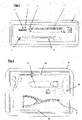
- the figure 2 also describes a kit of instruments (10) for single use, sterile packaged for the placement or removal of implants.
- kit of instruments (10) for single use, sterile packaged for the placement or removal of implants.
- the materials or coatings used for the manufacture of this instrument kit (10) are the same as those which can be used for the manufacture of the tubes (7) and (8).
- This instrument kit device (10) has many advantages such as reducing the overall cost of spinal surgery, and guaranteeing non-contamination from one patient to another, and therefore significantly reducing the number of nosocomial infection.
- This instrument kit device (10) is mainly composed of screwdriver bars, handles and pliers.
- the instrument kit (10) makes it possible to perform the following surgical procedures: the positioning of the screws (2) in the pedicles of the vertebrae, the bending of the rod (6) to be in accordance with the patient's anatomy, the placement of the rod (6) regardless of the insertion efforts, the placement of the plug (3), the correction maneuvers of the instrumented vertebrae of the compression and distraction type, the controlled and secure final tightening of the cap (3).
- the instrument kit (10) includes trial rods enabling the surgeon to determine the optimum length and curvature before choosing the rods (6) which will be implanted.
- the same kit of instruments (10) can be used for removing the material after osteosynthesis, or for any other clinical reasons.
- tubes (7) and (8) pre-mounted respectively on the screw (2) and the cap (3) are also multifunctional.
- instrument kit (10) and tubes (7) and (8) pre-mounted allows the surgeon the minimally invasive surgical approach median, lateral or bilateral.
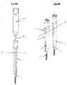
- the figures 3a and 3b describe in the preferred embodiment of hanging the mounting tube (7) on the screw (2).
- the head of the screw (5) has on its outer surface two indentations (20) made on either side of the U-shaped channel (25).
- the cavity is composed of a channel (27) and an interior housing (21).
- the mounting tube (7) is composed of two half-shells (30, 31).
- the female shape of the imprint on the screw head (5) is reproduced in male on the proximal ends of the half-shells (30 and 31).
- the male outer shape of the screw head (5) is reproduced in the female inner shape (22) at the proximal end of the two half-shells in order to solidify and secure in all directions (except that of rotation with the point of center of rotation the inner cavity (21)) the two half-shells (30 and 31) and the screw (2).
- each half-shell has at the proximal end a cavity of shape complementary to the shape of one of the branches of the screw head (5).
- the branches of the latter are trapped in the cavities provided on each of the proximal ends of the half-shells, the wall delimiting each cavity “ marrying “substantially the outer surface of the branches of the screw head (5).
- the cavity of each proximal end includes a lug formed so that, when the proximal ends are placed on the screw head (5), the lug is housed in the recess provided on the screw head.
- the recesses are made at the level of the upper end of the screw head (5).
- the inner housing (21) is arranged to allow the positioning of the half-shell by rocking/rotating the latter on the screw head (5) in the direction (A) with the housing as the point of rotation. interior (21).
- This form of male/female impression with an interior housing (21) has the advantage of being unremovable when the two half-shells are contiguous in their distal parts ( Picture 4a ), and allows easy dismantling when these two half-shells (30 and 31) are no longer contiguous ( Figure 5 ).
- the 3c and 3d figures respectively illustrate two examples of indentation shapes.
- the channel (27) forms with the housing (21) a receiving cavity having an internal height L2 greater than the height L1 of the inlet opening (27a). This dimensional difference makes it possible to lock the proximal end of the mounting tube (7) on the screw head (5). at least in translation along the axes (x, y).
- the dimensional difference is carried on the bottom of the cavity, under the inlet opening (27a) in order to allow disassembly of the half-shells (7) by tilting of the latter on the rim lower support (21a) delimiting the inlet opening (27a).
- the mounting tube (7) is molded onto the screw.
- the mounting tube (7) is provided with a light (32) in the continuity of the U-shape (25) of the screw head (5) in order to allow the passage and the introduction of the rod (6) ( Figure 10b and 10c ).
- the distal part of the tube (7) is provided with a thread (35) and an indentation (36).
- This thread (35) is provided to receive a thrust element (60) of the blocking element holder tube (8), and the recess (36) is provided to receive a perpendicular holding element (70) ( Figure 10g ).
- the thread (35) is made on the surface opposite the surface on which the indentation is made.
- the thread is formed on the internal surface of the distal part of the tube (7) and the indentation (36) on the external surface of said tube.
- the mounting tube (7) is not shown in its one-piece version, but only in the two preferred embodiments as described below.
- the outer shape of the tube can be of any shape such as oval or even hexagonal whatever the version.
- the tube (7) on the bone anchoring implant (2) can be obtained by different designs, not shown.
- the tube (7) can be made up of 2 arms forming a clamp, a fork with its closure system for holding the implant, or even in a non-limiting manner, a one-piece tube and its means of attachment to the implant, the connection means (21) of the implant being in line with the design of the tube (7).
- the figure 5 described in a preferred embodiment for the junction between the two half-shells.
- the two half-shells (30 and 31) are identical, and are interconnected by a tenon (33)/mortise (34) device.
- these two half-shells can be glued, welded, clipped, interlocked, but the preferred embodiment consists of a junction via a complementary ring (40) ( Figure 4a and 4b ).
- the ring which receives the thread (35) and the recess (36) provided at the distal end of the mounting tube (7).
- the inner shape of the ring corresponds to the outer shape of the mounting tube (7) here composed of two half-shells.
- the ring is provided with at least one bayonet (41) in the thickness of the ring (40).
- the latter comprises at least one pin (42) facing the bayonet(s).
- a compression spring is interposed between the two elements. The assembly and disassembly of the ring and of the two half-shells are thus simplified.
- the ring (40) is fixed by at least one through pin (43).
- this pin is subjected to shearing forces between the torque necessary for tightening the stopper (3) and the counter torque exerted by the perpendicular holding element (70) via the recess ( 36).
- the through pin (43) is sized to break under the shearing force.
- the breaking torque is a function of the optimum tightening torque of the plug (3).
- the ring (40) is detached from the tube (7) when the final tightening of the implant is carried out, and the dismantling of the two half-shells is thus simplified.
- the figures 6 and 7 show the blocking element holder tube (8) pre-mounted on the cap (3), as well as its interconnection in the assembly tube (7) of the screw (2).
- the blocking element holder tube (8) is arranged to securely hold the stopper (3) in its proximal part.
- the tube assembly carrying blocking element (8) and the stopper (3) constitute the blocking assembly.
- the maintenance of the stopper (3) is ensured by a thread arranged in the tube holding the locking element (8).
- this thread is slightly different from the thread of the stopper (3) in order to ensure its maintenance by wedging.
- the maintenance of the stopper (3) is ensured by clipping.
- the distal end of the locking assembly is provided with two lugs (50) on either side of the plug (3), of a length at least equivalent to the height of the plug relative to the lower face thereof to come into contact with the rod (6).
- the width of these tabs (50) cannot be greater than the diameter of the rod (6).
- the function of these two lugs is to allow the support on the rod (6) without contact of the stopper (3) neither on the head of the screw (5), nor on the rod (6), until the contact of this said rod on the fastening element of the screw (5), or the bottom of the U-shaped channel (25).
- the outer shape of the blocking element holder tube (8) is provided with at least one dovetail (51) of a shape complementary to the inner shape of the mounting tube (7) of the screw ( 2).
- the blocking element holder tube (8) is provided with two dovetails (51), one on each half-shell.
- the total length of the blocking element holder tube (8) is greater than the mounting tube (7), or else the two half-shells + ring. It is thus possible to remove the blocking element holder tube (8), once the stopper (3) has been put in place.
- the distal part (52) of the tube carrying the blocking element (8) and the internal shape (62) of the pushing element (60) are compatible for the establishment of the rod (6) at the bottom of the U-shaped housing (25), fastening element of the screw (2).
- this shape (52) is cylindrical.
- the thrust of the tube (8) by the thrust element (60) can be carried out at the end (53) of said tube, or else on the shoulder (54) formed by the arrangement of the form (52) .
- the internal diameter of the locking element holder tube (8) is provided for the passage of the screwdriver.
- the locking element holder tube (8) therefore also acts as a rod pusher.
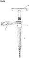
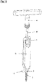
- the pusher element (60) of the blocking element (8)/rod pusher holder tube is the T-handle (60) which is provided with a thread (61) corresponding to that of the distal end of the assembly (7) of the screw (2) as shown in the figure 8 , 10 and 11 .
- this T-handle is cannulated (63) over its entire length, allowing the cap screwdriver bar (80') to pass through.
- this handle (60) is dynamometrically adjusted to the optimum tightening torque of the plug (3) blocking the rod connecting element (6).
- the dynamometer mechanism is made up of two notched rings (64) and (65), and a series of “Belleville” washers (66) or springs.
- the proximal meshing parts of the different screwdriver bars (80 and 80') are different in order to allow only the dynamometric function on the screwdriver bar intended for tightening the stopper.
- the bar screwdriver (80') for tightening the cap (3) has a break point so as to break under the tightening force.
- the breaking torque is a function of the optimum tightening torque of the cap (3).
- the screwdriver bar (80') can be made up of 2 longitudinally interconnected parts, an end piece with the breaking point and the screwdriver bar itself. The tip then forms an integral part of the blocking assembly (8 and 3).
- the figure 9 shows the perpendicular holding element (70) of the tube (7).
- This perpendicular holding element (70) is provided on one of its ends with a recess (71) complementary to that of the distal end of the mounting tube (7) of the screw (2).
- the recess (71) is formed by notches (72).
- this imprint (71) can take the form of a hexagon, a polygon, or even a hexalobe cited by way of example, the desired aim being to maintain the perpendicular element in rotation.
- retainer (70) on the tube (7) can take the form of a hexagon, a polygon, or even a hexalobe cited by way of example, the desired aim being to maintain the perpendicular element in rotation. retainer (70) on the tube (7).
- this perpendicular holding element (70) also constitutes a straight handle and makes it possible to receive the various screwdriver bars (80 and 80').
- a footprint (73) is provided for this purpose.
- a complementary imprint (76) is arranged on the side of the handle, when it is considered in its straight position (we will speak later of a straight handle), so that it can be used as a compatible T-handle with screwdriver bars (80 and 80').
- this straight handle (70) is provided in one of its ends with a complementary shape (75) to the external shape of the screw head (5).
- This straight handle therefore makes it possible, when tightening or loosening the cap, to effect a counter-torque effect both when the mounting tube (7) is in place and when the latter is dismantled.
- this straight handle is cannulated over its entire length, allowing the stopper screwdriver bar (80') to pass through.
- the handle is arranged to securely hold the clamping plug (3) in its end close to the complementary shape (75) to the head of the screw (5). This possibility makes it possible to put the plug (3) in place in the screw (2) if the mounting tube (7) is not in place.
- this maintenance is ensured by an internal thread (76) of identical shape to the stopper (6), or slightly different in order to ensure the maintenance of said stopper (6) by wedging.
- the cap is held in place by clipping.
- the compression and distraction forceps form a single forceps.
- these clamps are composed of two articulated arms, the proximal parts of these clamps being made up of forks coming to overlap the rod (6), these same forks coming to exert on the implants, the compression / distraction forces wanted.
- the figure 12 represents the compression clamp (90).
- This gripper is mainly composed of two arms (91) and (92), and of an articulation (93).
- Each arm (91) and (92) is provided with a curved end (94) and (95) terminated by said fork shape.
- the joint (93) is easily removable.
- the figure 13 represents these same arms (91) and (92) used for a distraction maneuver.
- Advantage is taken of the curved shape of the two curved proximal ends (94) and (95), so that they can “roll” one over the other, and thus exert the distraction force between the screws ( 2) by compression of two arms (91) and (92).
- two curved proximal ends (94) and (95) have notches in their convex parts in order to prevent the front sliding of the two arms (91) and (92).
- the two curved proximal ends (94) and (95) comprise means (97) of interconnection in order to prevent the lateral sliding of the two arms (91) and (92).
- this interconnection is composed of a pin (98) formed in one of the curved proximal ends (94) or (95), and of a groove (99) formed in the other curved proximal end.
- the figure 15 describes a device (100) for performing spinal stabilization according to a second embodiment.
- the device (100) comprises two bone anchoring elements (2) pre-mounted integrally on mounting tubes (7) and two locking elements intended to lock the connecting rod (6) on the bone anchoring element, the blocking elements being pre-mounted on clamping tubes (8).
- the tubes (7) comprise a handle (60) and a screwdriver (80) pre-assembled. The arrangement of these elements will be described later, in relation to the figures 20, 21a and 21b .
- the tubes/screwdriver/handles/screws and tubes/blocking elements assembly are placed in a sealed packaging (120), in sterile packaging and for single use.
- the assembly thus packaged forms a bone anchoring kit making available, in order to achieve spinal stabilization using a connecting rod, two bone anchoring elements and two blocking elements.
- bone anchoring kits may be provided comprising more than two bone anchoring elements and two blocking elements pre-mounted on tubes as described above without thereby departing from the scope of the invention. 'invention.
- the figure 16 describes an instrument kit (110) for placing or removing implants according to a second embodiment of the invention.
- the instrument kit (110) is sterile packaged for single use.
- the instrument kit (110) comprises instruments for preparing the pedicle holes (spatula, tap feeler), as well as instruments necessary for the implantation of the pedicle screws and connecting rods (screwdriver bar 80, pliers 900, 950 and handles 60, 70). He noted that the pliers (900, 950) present in the instrument kit (110) have a double functionality which will be described later.
- the instrument kit (110) incorporates all of the characteristics for the instrument kit (10) previously described.
- the figures 17 to 19 show views of a tube (7) and a retaining ring (40) forming a device of the figure 15 .
- the tube (7) incorporates all the characteristics of the tube described previously.
- the means implemented to receive a thrust element (or T-handle) (60) as well as a perpendicular holding element (70) carried, in the example described above, by the ring 40, are now carried directly through the tube (7).
- the distal part (7a) of the tube (7) comprises an outer face (7b) provided with the recess (36) intended to receive the perpendicular holding element (70) and an inner face (7c) provided with the thread (35) to receive the thrust element (60).
- the cavity has a hexagonal shape.
- the distal part (7a) of the tube (7) comprises, in the extension of the recess (36), an external thread (7d) capable of cooperating with at least one tab (400) of complementary shape provided on the face internal (40a) of the ring (40), thus allowing the fixing of the ring at the distal end of the tube (7).
- the ring (40) has the sole function of maintaining the two half-shells (30, 31) relative to each other.
- the external thread made on each half-shell (30, 31) consists of a double screw thread in order to ensure that the thread is identical on each half-shell so that the thread resulting from the junction of the threads of the two half-shells is continuous.
- the ring (40) has an outer diameter smaller than the nominal diameter of the recess (36) when the two half-shells (30, 31) are in position to form the tube (7).
- This specific dimensioning of the ring (40) is intended to allow the passage of the perpendicular holding element (70) for its position at the level of the cavity (36).
- the distal part (7a) comprises a hole (700) provided at the level of the recess (36) to allow the passage of a screwdriver bar (80, 80') when the holding element (70) is used instead of the tube (7), as illustrated in the figure 22 .
- the tube (7) is used to replace the holding element (70), the tube thus having a handle function, and the holding element (70) to replace the tube (7 ).
- the figure 20 illustrates a sectional view along the XX-XX axis of the assembly mounting tube/screwdriver/anchor shown in figure 15 .
- the screwdriver bar (80) is pre-mounted on the anchoring element (2). More particularly, the proximal end (80a) of the screwdriver bar (80) is arranged to cooperate with the screw (2).
- the assembly comprises means making it possible to maintain the screwdriver bar (80) in the axis of the threaded part (4) of the anchoring element (2).
- the means for holding the screwdriver bar (80) in the axis of the bone anchoring element comprise lugs (800) provided on the internal face of the tube (7).
- the assembly advantageously comprises a holding fin (60') for the screwdriver bar 80 in a given position with respect to the tube (7) and to the screw (2).
- the retaining fin (60'), T-shaped, is pre-mounted on the distal end of the tube (7). It comprises, in its lower part, a thread (61') corresponding to the internal thread (35) of the distal part of the tube (7).
- the retaining fin (60') comprises, over its entire length, a channel through which the screwdriver bar (80) passes.
- the retaining fin (60') is arranged to ensure axial retention of the screwdriver bar (80) in the tube (7) while allowing rotational movement of the bar inside the tube (7) and this in order to allow the rotational drive of the threaded part (4) of the screw (2), the head (5) of the screw remaining fixed relative to the bar.
- it is arranged to keep the alignment of the screwdriver bar (80) in alignment with the bone anchoring element (2).
- Such a pre-assembly also has the advantage of allowing on the one hand a saving of surgical time, the operation of positioning the screwdriver bar on the bone anchoring element being eliminated and on the other hand a limitation operational risk, the duration of anesthesia being reduced.
- Such a pre-assembly also has the advantage of avoiding any pairing problem of screwdriver bar/screw.
- the tube (7) can be used as a perpendicular handle and the perpendicular handle (70) as a guide tube for a plug screwdriver bar (80') ( figure 22 ).
- the figures 23a and 23b represent a compression forceps (900) contained in the instrument kit (110).
- the compression clamp (900) which has a plane of symmetry P, comprises two arms (910), (920) mounted articulated relative to each other. In the embodiment described, the arms are arranged crossed with respect to each other.
- each arm (910, 920) has a curved end (930) in the form of a fork, the ends (930) in the form of a fork of each arm being arranged facing one another with respect to to the plane of symmetry so as to be able to overlap the rod (6).
- the opposite ends (940) to the compression ends (930) are arranged to allow gripping of the rod (6) by bringing the arms (910, 920) closer together.
- the ends of grip (940) of each arm (910, 920) have two fingers defining a space for receiving the rod (6).
- the compression clamp (900) makes it possible, by means of its compression ends (930), to exert a compressive force on the bone anchoring elements, as illustrated in the figure 23b , and by means of its gripping ends (940), opposite the compression ends, to hold the rod, as illustrated in the figure 23a .
- This dual functionality makes it possible to reduce the number of instruments necessary for placing the implant and therefore to reduce the number of instruments to be handled accordingly.
- the articulation (901) is provided so that the distance between the compression ends (930) and the articulation (901) is less than the distance between the ends of grip (940) and the articulation (901), the distance being considered along the longitudinal axis of the gripper.
- the figures 24a and 24b represent a distraction forceps (950) contained in the instrument kit (100).
- the distraction forceps (950) which has a plane of symmetry P', comprises two arms (960), (970) joined to one another by a hinge (951).
- each end (980) of each arm (960, 970), configured in the form of a fork, is arranged to be able to overlap a rod (6) as illustrated in the figures 24a and 24b .
- the ends will be able to exert the desired distraction/compression forces on the rod (6).
- This dual functionality makes it possible to reduce the number of instruments necessary for placing the implant and therefore to reduce the number of instruments to be handled accordingly.
- the articulation (951) is provided so that the distance between the distraction extremities (980) and the articulation (951) is less than the distance between the compression extremities (990) and the articulation (951), the distance being considered along the longitudinal axis of the gripper.
- the distraction clamp (950) makes it possible, by means of its ends, to exert a distraction force on the implants, as illustrated in the figure 24b , and by means of the opposite ends, to exert a compressive force of great amplitude, as illustrated in the figure 24a .
- the figures 25a to 25c illustrate the steps for mounting a plug (3) on the head (5) of screw (2) while the mounting tube (7) has been removed from the screw (2).
- the tube (8) carrying the cap (3) is placed on the screw head (5) by sliding the tube (8) along one of the half-shells (30, 31) mounted on the head ( 5) screws.
- the half-shell (30) thus makes it possible to guide the stopper (3) towards the screw head.
- the stopper screwdriver bar (80') is inserted into the duct of the blocking tube (8) to tighten the stopper (3) on the rod (6) (not shown in the figures but present) and on the screw head (5) ( figure 25c ).
- the embodiment illustrated in the figures 25a to 25c is advantageous in that only one half-shell of the tube (7) is necessary to allow the guiding and positioning the cap (3) on the head (5).
Landscapes
- Health & Medical Sciences (AREA)
- Orthopedic Medicine & Surgery (AREA)
- Neurology (AREA)
- Life Sciences & Earth Sciences (AREA)
- Surgery (AREA)
- Heart & Thoracic Surgery (AREA)
- General Health & Medical Sciences (AREA)
- Biomedical Technology (AREA)
- Nuclear Medicine, Radiotherapy & Molecular Imaging (AREA)
- Medical Informatics (AREA)
- Molecular Biology (AREA)
- Animal Behavior & Ethology (AREA)
- Engineering & Computer Science (AREA)
- Public Health (AREA)
- Veterinary Medicine (AREA)
- Surgical Instruments (AREA)
- Prostheses (AREA)
- Electrotherapy Devices (AREA)
- Pharmaceuticals Containing Other Organic And Inorganic Compounds (AREA)
Claims (28)
- Vorrichtung (1, 100) zur Befestigung von Wirbeln auf dem minimal-invasive chirurgische posterioren oder posterior-lateralen Weg, wobei die Vorrichtung (1) mindestens folgendes umfasst:- ein Knochenverankerungselement (2), wie zum Beispiel eine Pedikelschraube oder Wirbelschraube, welches einen proximalen Teil (5) aufweist, der mit einer Grenzfläche versehen ist, um ein Verbindungselement (6), wie zum Beispiel eine Stange oder ein Plättchen, mit einem distalen Teil mit Gewinde (4) zu verbinden,dadurch gekennzeichnet, dass sie Folgendes umfasst:- ein fest auf dem Knochenverankerungselement (2) vormontiertes Montagerohr (7), wobei sich das Montagerohr (7), bestehend aus zwei Halbschalen (30, 31), jeweils ein proximales Ende aufweisen, dass so angeordnet ist, dass es in das Knochenverankerungselement (2) eingreift und an ihrem distalen Ende fest aneinander liegen und die an ihren distalen Teilen aneinander liegen, vom Knochenverankerungselement (2) abmontieren lässt, und- ein Schraubendreherstab (80) umfasst, welches durch das Montagerohr (7) führt und auf dem Knochenverankerungselement (2) ein vormontiertes Endstück aufweist- eine versiegelte Verpackung zum sterilen Verschluss (1) des Knochenverankerungselements (2) und des Montagerohrs (7) und des Schraubendreherstab (80) vormontierten.
- Vorrichtung (1, 100) zur Befestigung von Wirbeln nach Anspruch 1, dadurch gekennzeichnet, dass das Montagerohr (7) eine längliche Öffnung (32) aufweist, die zum proximalen Teil (5) des Knochenverankerungselements (2) führt, um das Verbindungselement (6) hindurchführen zu können.
- Vorrichtung (1, 100) zur Befestigung von Wirbeln nach Anspruch 1 oder Anspruch 2, dadurch gekennzeichnet, dass die Vorrichtung des Weiteren ein blockierendes Element (3) aufweist, wobei der Innendurchmesser des Montagerohrs (7) die Durchführung des blockierenden Elements (3) des Verbindungselements bis auf das Knochenverankerungselement ermöglicht.
- Vorrichtung (1, 100) zur Befestigung von Wirbeln nach einem der Ansprüche 1 bis 3, dadurch gekennzeichnet, dass das Montageohr (7) mit Mitteln versehen ist, die das Hilfsmittel in der Ausrichtung des Knochenverankerungselements (2) halten.
- Vorrichtung (1, 100) zur Befestigung von Wirbeln nach Anspruch 4, dadurch gekennzeichnet, dass die Haltemittel an der Innenseite des Montagerohrs (7) Stifte aufweisen.
- Vorrichtung (1, 100) zur Befestigung von Wirbeln nach Anspruch 4 oder 5, dadurch gekennzeichnet, dass die Haltemittel einen Halteflügel (60') umfassen, der auf dem Endstück des Montagerohrs (7) gegenüber dem Endstück mit dem Knochenverankerungselement (2) montiert ist.
- Vorrichtung (1, 100) zur Befestigung von Wirbeln nach Anspruch 6, dadurch gekennzeichnet, dass der Halteflügel (60') in Bezug auf das Montagerohr (7) so angeordnet ist, dass eine Drehbewegung des Hilfsmittels im Innern des Montagerohrs (7) möglich ist.
- Vorrichtung (1, 100) zur Befestigung von Wirbeln nach einem der vorhergehenden Ansprüche, dadurch gekennzeichnet, dass das Montagerohr (7) aus Verbundmaterial, Polymer, Eisen- oder Nichteisenlegierung oder einer Kombination dieser Materialien hergestellt ist.
- Vorrichtung (1, 100) zur Befestigung von Wirbeln nach einem der vorhergehenden Ansprüche, dadurch gekennzeichnet, dass das Montagerohr (7) auf das Knochenverankerungselement aufgeformt ist.
- Vorrichtung (1, 100) zur Befestigung von Wirbeln nach einem der vorhergehenden Ansprüche, dadurch gekennzeichnet, dass das Montagerohr (7) am distalen Ende eine Prägung (36) zur Aufnahme eines senkrechten Halteelements (70), wie zum Beispiel eines Griffs, enthält.
- Vorrichtung (1, 100) zur Befestigung von Wirbeln nach einem der vorhergehenden Ansprüche, dadurch gekennzeichnet, dass die beiden Halbschalen an ihrem distalen Ende durch einen Ring (40) aneinandergedrückt werden.
- Vorrichtung (1, 100) zur Befestigung von Wirbeln nach Anspruch 11, dadurch gekennzeichnet, dass das Montagerohr (7) und der Ring (40) so angeordnet sind, dass sie eine steife Einheit bilden.
- Vorrichtung (1, 100) zur Befestigung von Wirbeln nach einem der Ansprüche 1 bis 12, dadurch gekennzeichnet, dass die beiden Halbschalen (30,31) so angeordnet sind, dass sie, wenn sie aufeinander liegen, ein Führungsrohr bilden.
- Vorrichtung (1, 100) zur Befestigung von Wirbeln nach Anspruch 13, dadurch gekennzeichnet, dass das durch die beiden Halbschalen gebildete Führungsrohr einen Innendurchmesser aufweist, der das Durchführen eines blockierenden Elements (3) des Verbindungselements bis auf das Knochenverankerungselement (2) ermöglicht.
- Vorrichtung (1, 100) zur Befestigung von Wirbeln nach Anspruch 13 oder Anspruch 14, dadurch gekennzeichnet, dass das durch die beiden Halbschalen gebildete Führungsrohr einen Innendurchmesser aufweist, der das Durchführen der Hilfsmittel zum Einsetzen des blockierenden Elements ermöglicht.
- Vorrichtung (1, 100) zur Befestigung von Wirbeln nach einem der Ansprüche 3 bis 15, dadurch gekennzeichnet, dass das blockierende Element (3) fest mit einem Trägerrohr (8) für das blockierende Element vormontiert wird, um eine blockierende Einheit zu bilden, wobei das blockierende Element (3) vom Trägerrohr (8) des blockierenden Elements abmontiert werden kann.
- Vorrichtung (1, 100) zur Befestigung von Wirbeln nach Anspruch 16, dadurch gekennzeichnet, dass die blockierende Einheit steril verpackt ist.
- Vorrichtung zur Befestigung von Wirbeln nach Anspruch 16 oder Anspruch 17, dadurch gekennzeichnet, dass die blockierende Einheit steril in der versiegelten Verpackung (1) verschlossen ist.
- Vorrichtung (1, 100) zur Befestigung von Wirbeln nach einem der Ansprüche 16 bis 18, dadurch gekennzeichnet, dass das Trägerrohr (8) des blockierenden Elements so bemessen ist, dass es in das Montageohr (7) eingeschoben werden kann.
- Vorrichtung (1, 100) zur Befestigung von Wirbeln nach Anspruch 19, dadurch gekennzeichnet, dass das Montagerohr (7) eine rohrförmige Innenwand aufweist, die mit mindestens einem Indexierungsrelief versehen ist, wobei das Trägerrohr des blockierenden Elements ein Indexierungsrelief aufweist, dessen Form das Indexierungsrelief des Montagerohrs (7) ergänzt.
- Vorrichtung (1, 100) zur Befestigung von Wirbeln nach einem der Ansprüche 16 bis 20, dadurch gekennzeichnet, dass das Trägerrohr (8) des blockierenden Elements einen proximalen Teil aufweist, der mit einem Auflagerelief versehen ist, welches sich gegenüber der Verbindungsgrenzfläche des Knochenverankerungselements (2) befindet, wenn das Trägerrohr (8) des blockierenden Elements in das Montagerohr (7) eingeschoben wird, um ein Verbindungselement (6) auf die Verbindungsgrenzfläche des Knochenverankerungselements (2) zu drücken.
- Vorrichtung (1, 100) zur Befestigung von Wirbeln nach einem der Ansprüche 16 bis 21, dadurch gekennzeichnet, dass es des Weiteren ein Schubelement (60) aufweist, das mit dem Trägerrohr (8) des blockierenden Elements zusammenwirkt, um das Trägerrohr (8) des blockierenden Elements in das Montageohr (7) zu schieben.
- Vorrichtung (1, 100) zur Befestigung von Wirbeln nach einem der Ansprüche 16 bis 22, dadurch gekennzeichnet, dass das Montagerohr (7), wenn das Trägerrohr (8) des blockierenden Elements darin positioniert ist, ein Führungsrohr bildet.
- Vorrichtung (1, 100) zur Befestigung von Wirbeln nach einem der Ansprüche 16 bis 23, dadurch gekennzeichnet, dass das Montageohr (7) und das Trägerrohr (8) des blockierenden Elements, wenn dieses darin positioniert ist, eine steife Einheit bilden.
- Vorrichtung (1, 100) zur Befestigung von Wirbeln nach einem der Ansprüche 16 bis 24, dadurch gekennzeichnet, dass das Trägerrohr (8) des blockierenden Elements eine Innenform aufweist, die das Durchführen eines Schraubendrehers ermöglicht.
- Vorrichtung (1, 100) zur Befestigung von Wirbeln nach einem der Ansprüche 16 bis 25, dadurch gekennzeichnet, dass das Trägerrohr (8) des blockierenden Elements aus Verbundmaterial, Polymer, Eisen- oder Nichteisenlegierung oder einer Kombination dieser Materialien gebildet wird.
- Vorrichtung zur Befestigung von Wirbeln nach einem der vorhergehenden Ansprüche, dadurch gekennzeichnet, dass alle Teile der Vorrichtung zum einmaligen Gebrauch bestimmt sind.
- Vorrichtung (1, 100) zur Befestigung von Wirbeln nach einem der vorhergehenden Ansprüche, dadurch gekennzeichnet, dass alle Teile der Vorrichtung in einer oder mehreren versiegelten Verpackungen (1,10) steril verschlossen sind.
Applications Claiming Priority (3)
| Application Number | Priority Date | Filing Date | Title |
|---|---|---|---|
| FR0906369A FR2954689B1 (fr) | 2009-12-28 | 2009-12-28 | Dispositif et methode pour la chirurgie rachidienne. |
| EP10810769A EP2519180A2 (de) | 2009-12-28 | 2010-12-28 | Vorrichtung und verfahren zur wirbelsäulenchirurgie |
| PCT/FR2010/000880 WO2011080426A2 (fr) | 2009-12-28 | 2010-12-28 | Dispositif et méthode pour la chirurgie rachidienne |
Related Parent Applications (2)
| Application Number | Title | Priority Date | Filing Date |
|---|---|---|---|
| EP10810769A Division EP2519180A2 (de) | 2009-12-28 | 2010-12-28 | Vorrichtung und verfahren zur wirbelsäulenchirurgie |
| EP10810769.9 Division | 2010-12-28 |
Publications (3)
| Publication Number | Publication Date |
|---|---|
| EP2526888A1 EP2526888A1 (de) | 2012-11-28 |
| EP2526888B1 EP2526888B1 (de) | 2018-04-18 |
| EP2526888B2 true EP2526888B2 (de) | 2022-07-27 |
Family
ID=42358132
Family Applications (2)
| Application Number | Title | Priority Date | Filing Date |
|---|---|---|---|
| EP12177688.4A Active EP2526888B2 (de) | 2009-12-28 | 2010-12-28 | Vorrichtung für die Wirbelchirurgie |
| EP10810769A Withdrawn EP2519180A2 (de) | 2009-12-28 | 2010-12-28 | Vorrichtung und verfahren zur wirbelsäulenchirurgie |
Family Applications After (1)
| Application Number | Title | Priority Date | Filing Date |
|---|---|---|---|
| EP10810769A Withdrawn EP2519180A2 (de) | 2009-12-28 | 2010-12-28 | Vorrichtung und verfahren zur wirbelsäulenchirurgie |
Country Status (10)
| Country | Link |
|---|---|
| US (3) | US10219845B2 (de) |
| EP (2) | EP2526888B2 (de) |
| JP (4) | JP5975882B2 (de) |
| AU (1) | AU2010338092A1 (de) |
| BR (1) | BR112012016082A2 (de) |
| CA (1) | CA2785872C (de) |
| ES (1) | ES2677845T5 (de) |
| FR (1) | FR2954689B1 (de) |
| WO (1) | WO2011080426A2 (de) |
| ZA (2) | ZA201205701B (de) |
Cited By (1)
| Publication number | Priority date | Publication date | Assignee | Title |
|---|---|---|---|---|
| RU2820924C1 (ru) * | 2023-03-29 | 2024-06-11 | Федеральное Государственное бюджетное образовательное учреждение высшего образования Дагестанский государственный медицинский университет Министерства здравоохранения Российской Федерации | Устройство для удержания винта на рабочем конце отвертки при остеосинтезе |
Families Citing this family (56)
| Publication number | Priority date | Publication date | Assignee | Title |
|---|---|---|---|---|
| US20150105831A1 (en) * | 2009-10-09 | 2015-04-16 | Synthes Usa, Lla | Tightening device for spine surgery |
| FR2954689B1 (fr) * | 2009-12-28 | 2012-12-21 | Sterispine | Dispositif et methode pour la chirurgie rachidienne. |
| US8603094B2 (en) | 2010-07-26 | 2013-12-10 | Spinal Usa, Inc. | Minimally invasive surgical tower access devices and related methods |
| US9198692B1 (en) * | 2011-02-10 | 2015-12-01 | Nuvasive, Inc. | Spinal fixation anchor |
| US9198698B1 (en) | 2011-02-10 | 2015-12-01 | Nuvasive, Inc. | Minimally invasive spinal fixation system and related methods |
| US9295501B2 (en) * | 2011-08-02 | 2016-03-29 | Blackstone Medical, Inc. | Bayonet counter-torque wrench |
| US9125703B2 (en) * | 2012-01-16 | 2015-09-08 | K2M, Inc. | Rod reducer, compressor, distractor system |
| WO2013112689A2 (en) * | 2012-01-25 | 2013-08-01 | Spinal Usa, Inc. | Minimally invasive devices and methods for delivering fixation devices and implants into a spine |
| FR2988582B1 (fr) | 2012-04-02 | 2014-03-14 | Safe Orthopaedics | Kit d'instrumentation |
| FR2988993B1 (fr) * | 2012-04-05 | 2014-03-21 | Safe Orthopaedics | Instrument et systeme chirurgical pour la fixation des vertebres |
| FR2990839B1 (fr) * | 2012-05-28 | 2015-03-06 | Safe Orthopaedics | Dispositif rachidien comprenant des moyens d’accroche reversible |
| FR2990840B1 (fr) | 2012-05-28 | 2017-01-20 | Safe Orthopaedics | Systeme d'instrumentation pour la realisation d'une intervention chirurgicale sur des vertebres comprenant des moyens de blocage temporaire |
| FR2993449B1 (fr) | 2012-07-19 | 2014-07-11 | Safe Orthopaedics | Dispositif de guidage d'un instrument chirurgical en position sur un element d'ancrage osseux comprenant des moyens de realignement d'une tige de liaison avec l'element d'ancrage |
| FR3001628B1 (fr) * | 2013-02-05 | 2017-11-24 | Safe Orthopaedics | Ensemble d'implantation comprenant un instrument d'entrainement pre-monte sur un implant osseux. |
| US20140336709A1 (en) * | 2013-03-13 | 2014-11-13 | Baxano Surgical, Inc. | Multi-threaded pedicle screw system |
| US9510875B2 (en) | 2013-03-14 | 2016-12-06 | Stryker European Holdings I, Llc | Systems and methods for percutaneous spinal fusion |
| US9259247B2 (en) | 2013-03-14 | 2016-02-16 | Medos International Sarl | Locking compression members for use with bone anchor assemblies and methods |
| EP3505111B1 (de) | 2013-05-13 | 2020-06-03 | Neo Medical SA | Orthopädisches implantat-set |
| US9918753B2 (en) * | 2013-08-13 | 2018-03-20 | Warsaw Orthopedic, Inc. | Spinal implant system and method |
| US9526529B2 (en) | 2013-09-25 | 2016-12-27 | Blackstone Medical, Inc. | Bone screw systems with pressure caps having biasing members |
| US9480501B2 (en) | 2013-10-21 | 2016-11-01 | Blackstone Medical, Inc. | Modular pedicle screw |
| JP2016538086A (ja) | 2013-11-26 | 2016-12-08 | キセンコ メディカル,エルエルシー | 固定および解放インプラント送達システム |
| US9980758B2 (en) | 2013-11-27 | 2018-05-29 | Blackstone Medical, Inc. | Minimally invasive counter-torque wrench system |
| US20150230926A1 (en) | 2014-02-18 | 2015-08-20 | Biomet Manufacturing, Llc | Method and device for reducing implant contamination from handling |
| US9526553B2 (en) * | 2014-04-04 | 2016-12-27 | K2M, Inc. | Screw insertion instrument |
| US10485528B2 (en) * | 2015-02-05 | 2019-11-26 | Spinal Generations, Llc | Individual packaging arrangement for orthopedic tools |
| EP3103406B1 (de) * | 2015-06-10 | 2017-10-04 | Biedermann Technologies GmbH & Co. KG | Aufnahmeteil einer knochenverankerungsvorrichtung und knochenverankerungsvorrichtung mit solch einem aufnahmeteil |
| US10123829B1 (en) | 2015-06-15 | 2018-11-13 | Nuvasive, Inc. | Reduction instruments and methods |
| US10194960B1 (en) | 2015-12-03 | 2019-02-05 | Nuvasive, Inc. | Spinal compression instrument and related methods |
| BR112018014064B1 (pt) * | 2016-01-15 | 2023-01-10 | Neo Medical Sa | Ferramenta dual de compressão e de expansão para operações cirúrgicas |
| US10413337B2 (en) | 2016-03-03 | 2019-09-17 | Paradigm Spine, Llc | Instruments for interspinous or interlaminar stabilization devices |
| EP3478193A4 (de) * | 2016-07-04 | 2020-07-15 | Spinal Balance, Inc. | Kombination aus schutzbehälter und ausgabevorrichtung für pedikelschrauben |
| US10052140B2 (en) | 2016-10-05 | 2018-08-21 | Stryker European Holdings I, Llc | Apparatus and method for fenestrated screw augmentation |
| US10779866B2 (en) | 2016-12-29 | 2020-09-22 | K2M, Inc. | Rod reducer assembly |
| US10349986B2 (en) * | 2017-04-20 | 2019-07-16 | Warsaw Orthopedic, Inc. | Spinal implant system and method |
| US10973558B2 (en) | 2017-06-12 | 2021-04-13 | K2M, Inc. | Screw insertion instrument and methods of use |
| US11076894B2 (en) * | 2017-06-23 | 2021-08-03 | Stylitech | System for inserting and removing a locator-pin in a bone |
| CN108210060A (zh) * | 2018-01-05 | 2018-06-29 | 中国人民解放军第四军医大学 | 一种双用钳 |
| GB2609323B (en) * | 2018-05-09 | 2023-04-19 | Zimmer Biomet Spine Inc | Anchoring device with extended tabs |
| US10923872B2 (en) * | 2018-05-31 | 2021-02-16 | Teradyne, Inc. | Tool for disconnecting a connector |
| USD919087S1 (en) * | 2018-06-19 | 2021-05-11 | Orthocision Inc. | Surgical tool |
| US10959859B2 (en) * | 2018-07-25 | 2021-03-30 | Warsaw Orthopedic, Inc. | Spinal implant system and method |
| US11484350B2 (en) | 2018-12-13 | 2022-11-01 | Zimmer Biomet Spine, Inc. | Split tower for a bone anchor |
| CN119523608A (zh) * | 2019-03-26 | 2025-02-28 | 尼奥医疗公司 | 以两个不同扭矩水平拧紧骨科固定螺钉的系统 |
| US12251135B2 (en) | 2019-03-26 | 2025-03-18 | Neo Medical Sa | Set screw and set screw driving tool for improved rod alignment |
| DE102019110442A1 (de) | 2019-04-23 | 2020-10-29 | DREAMED Medical Trade UG (haftungsbeschränkt) | Set zur dorsalen Wirbelfusion und Handgriff |
| CN119318531A (zh) | 2019-07-02 | 2025-01-17 | 尼奥医疗公司 | 用于防止由于螺钉起子和螺钉延长器所引起的离轴力造成的骨结构上的侧向应力的方法、装置和系统 |
| US11134994B2 (en) * | 2020-01-30 | 2021-10-05 | Warsaw Orthopedic, Inc. | Spinal-correction system having threaded extender tabs and reduction tab extenders |
| US11439442B2 (en) * | 2020-04-16 | 2022-09-13 | Warsaw Orthopedic, Inc. | Modular screw system with head locker and derotator |
| US11617602B2 (en) * | 2020-04-16 | 2023-04-04 | Medtronic, Inc. | Systems, methods of use and surgical instruments employing a secure slide lock to fasten a head |
| FR3112071B1 (fr) * | 2020-07-02 | 2023-02-10 | Razian Hassan | Dispositif pour visser une vis pédiculaire |
| US12262927B2 (en) | 2020-12-10 | 2025-04-01 | K2M, Inc. | Screw insertion instrument and methods of use |
| CN112618050B (zh) * | 2020-12-18 | 2021-09-24 | 湖北省肿瘤医院(湖北省肿瘤研究所) | 一种医疗外科手术器械 |
| JP7573658B2 (ja) * | 2021-02-01 | 2024-10-25 | 京セラ株式会社 | 取外し器具および手術器具システム |
| AU2022230734A1 (en) | 2021-03-05 | 2023-10-19 | Medos International Sarl | Multi-feature polyaxial screw |
| US12127766B2 (en) | 2021-03-05 | 2024-10-29 | Medos International Sàrl | Selectively locking polyaxial screw |
Citations (2)
| Publication number | Priority date | Publication date | Assignee | Title |
|---|---|---|---|---|
| US20060217719A1 (en) † | 2005-03-24 | 2006-09-28 | Accin Corporation | Method and apparatus for bone stabilization |
| US20090222045A1 (en) † | 2008-02-28 | 2009-09-03 | K2M, Inc. | Minimally Invasive Retractor and Methods of Use |
Family Cites Families (90)
| Publication number | Priority date | Publication date | Assignee | Title |
|---|---|---|---|---|
| FR2208381A5 (de) * | 1972-11-23 | 1974-06-21 | France Etat | |
| US4409968A (en) * | 1980-02-04 | 1983-10-18 | Drummond Denis S | Method and apparatus for engaging a hook assembly to a spinal column |
| US4411259A (en) * | 1980-02-04 | 1983-10-25 | Drummond Denis S | Apparatus for engaging a hook assembly to a spinal column |
| US6241734B1 (en) * | 1998-08-14 | 2001-06-05 | Kyphon, Inc. | Systems and methods for placing materials into bone |
| US5487743A (en) * | 1994-02-15 | 1996-01-30 | Sofamore, S.N.C. | Anterior dorso-lumbar spinal osteosynthesis instrumentation for the correction of kyphosis |
| WO1998022035A1 (fr) | 1996-11-22 | 1998-05-28 | Philippe Berros | Trousse d'instruments chirurgicaux ou micro-chirurgicaux a usage unique |
| US6468279B1 (en) * | 1998-01-27 | 2002-10-22 | Kyphon Inc. | Slip-fit handle for hand-held instruments that access interior body regions |
| US6428541B1 (en) * | 1998-04-09 | 2002-08-06 | Sdgi Holdings, Inc. | Method and instrumentation for vertebral interbody fusion |
| US6283966B1 (en) * | 1999-07-07 | 2001-09-04 | Sulzer Spine-Tech Inc. | Spinal surgery tools and positioning method |
| FR2796545B1 (fr) * | 1999-07-22 | 2002-03-15 | Dimso Sa | Liaison poly-axiale pour systeme d'osteosynthese, notamment pour le rachis |
| US6273916B1 (en) | 1999-09-02 | 2001-08-14 | Cook Incorporated | Method and apparatus for strengthening vertebral bodies |
| US6743231B1 (en) | 2000-10-02 | 2004-06-01 | Sulzer Spine-Tech Inc. | Temporary spinal fixation apparatuses and methods |
| JP2003340233A (ja) * | 2002-05-30 | 2003-12-02 | Japan Gore Tex Inc | 吸湿材ユニット、および該吸湿材ユニットを有する準密閉型容器 |
| US6955678B2 (en) * | 2002-06-28 | 2005-10-18 | Smith & Nephew, Inc. | Soft tissue repair tool |
| US7189244B2 (en) * | 2002-08-02 | 2007-03-13 | Depuy Spine, Inc. | Compressor for use in minimally invasive surgery |
| US6783004B1 (en) * | 2002-09-17 | 2004-08-31 | Pilling Weck Incorporated | Kit of medical tools for removing screws |
| ES2629431T3 (es) * | 2002-10-30 | 2017-08-09 | Zimmer Spine, Inc. | Sistema de estabilización espinal por inserción |
| US20050182400A1 (en) * | 2003-05-02 | 2005-08-18 | Jeffrey White | Spine stabilization systems, devices and methods |
| US20050182401A1 (en) * | 2003-05-02 | 2005-08-18 | Timm Jens P. | Systems and methods for spine stabilization including a dynamic junction |
| US20050033430A1 (en) * | 2003-08-05 | 2005-02-10 | Russell Powers | Surgical kit and method for providing sterilized equipment for use in spinal surgery |
| DE10341697B3 (de) * | 2003-09-10 | 2004-10-07 | Felo-Werkzeugfabrik Holland-Letz Gmbh | Schraubwerkzeug mit einer Vorrichtung zur Begrenzung des übertragenen Drehmomentes |
| US8002798B2 (en) * | 2003-09-24 | 2011-08-23 | Stryker Spine | System and method for spinal implant placement |
| EP1691848B1 (de) * | 2003-10-23 | 2012-08-22 | TRANS1, Inc. | Werkzeuge und werkzeugsets zur durchführung von minimalinvasiven verfahren an der wirbelsäule |
| US7766920B2 (en) * | 2003-11-26 | 2010-08-03 | Synthes Usa, Llc | Cannulated fastener system |
| US7179261B2 (en) * | 2003-12-16 | 2007-02-20 | Depuy Spine, Inc. | Percutaneous access devices and bone anchor assemblies |
| US7842044B2 (en) * | 2003-12-17 | 2010-11-30 | Depuy Spine, Inc. | Instruments and methods for bone anchor engagement and spinal rod reduction |
| US7160300B2 (en) * | 2004-02-27 | 2007-01-09 | Jackson Roger P | Orthopedic implant rod reduction tool set and method |
| JP2007525274A (ja) * | 2004-02-27 | 2007-09-06 | ロジャー・ピー・ジャクソン | 整形外科インプラントロッド整復器具セット及び方法 |
| US7470279B2 (en) | 2004-02-27 | 2008-12-30 | Jackson Roger P | Orthopedic implant rod reduction tool set and method |
| JP2008541784A (ja) * | 2004-03-30 | 2008-11-27 | キナメッド・インコーポレーテッド | 手術用電動ねじ回し |
| US7272998B1 (en) * | 2004-06-16 | 2007-09-25 | Gauthier Michael T | Torque-limiting mechanism |
| EP1773205A2 (de) | 2004-06-16 | 2007-04-18 | Warsaw Orthopedic, Inc. | Chirurgische instrumente für die reparatur von wirbelkörpern |
| US7666189B2 (en) | 2004-09-29 | 2010-02-23 | Synthes Usa, Llc | Less invasive surgical system and methods |
| US20070239159A1 (en) | 2005-07-22 | 2007-10-11 | Vertiflex, Inc. | Systems and methods for stabilization of bone structures |
| EP1858422A4 (de) * | 2005-02-23 | 2011-12-28 | Pioneer Surgical Technology Inc | Minimalinvasives chirurgisches system |
| WO2008024937A2 (en) * | 2006-08-23 | 2008-02-28 | Pioneer Surgical Technology, Inc. | Minimally invasive surgical system |
| US7749232B2 (en) * | 2005-05-24 | 2010-07-06 | Anthony Salerni | Electromagnetically guided spinal rod system and related methods |
| DE102005030553A1 (de) * | 2005-06-22 | 2006-12-28 | Aesculap Ag & Co. Kg | Chirurgischer Schraubenbehälter |
| US7811309B2 (en) * | 2005-07-26 | 2010-10-12 | Applied Spine Technologies, Inc. | Dynamic spine stabilization device with travel-limiting functionality |
| US7909830B2 (en) * | 2005-08-25 | 2011-03-22 | Synthes Usa, Llc | Methods of spinal fixation and instrumentation |
| WO2007038351A2 (en) | 2005-09-23 | 2007-04-05 | Synthes (Usa) | Installation tools and system for bone support apparatus |
| US7846093B2 (en) | 2005-09-26 | 2010-12-07 | K2M, Inc. | Minimally invasive retractor and methods of use |
| US20070162124A1 (en) * | 2005-12-19 | 2007-07-12 | Whittaker Gregory R | Arthroscopic implants with integral fixation devices and method for use |
| US7927360B2 (en) * | 2006-01-26 | 2011-04-19 | Warsaw Orthopedic, Inc. | Spinal anchor assemblies having extended receivers |
| US7520879B2 (en) | 2006-02-07 | 2009-04-21 | Warsaw Orthopedic, Inc. | Surgical instruments and techniques for percutaneous placement of spinal stabilization elements |
| US20070219558A1 (en) * | 2006-03-15 | 2007-09-20 | Allen Deutsch | Method and apparatus for arthroscopic surgery using suture anchors |
| EP2010073A4 (de) * | 2006-04-21 | 2011-05-25 | Interventional Spine Inc | Verfahren und vorrichtung zur spinalen fixation |
| US7334509B1 (en) * | 2006-10-11 | 2008-02-26 | Bradshaw Medical, Inc. | Torque limiting driver and assembly |
| US8821549B2 (en) * | 2006-06-13 | 2014-09-02 | Anova Corporation | Methods and apparatus for anulus repair |
| US7976546B2 (en) * | 2006-08-04 | 2011-07-12 | Magrod, Llc | Magnetic targeting system for facilitating navigation |
| US7918857B2 (en) * | 2006-09-26 | 2011-04-05 | Depuy Spine, Inc. | Minimally invasive bone anchor extensions |
| US7947045B2 (en) * | 2006-10-06 | 2011-05-24 | Zimmer Spine, Inc. | Spinal stabilization system with flexible guides |
| US7967821B2 (en) * | 2006-11-20 | 2011-06-28 | Depuy Spine, Inc. | Break-off screw extension removal tools |
| US8221431B2 (en) * | 2006-12-18 | 2012-07-17 | Greatbatch Medical S.A. | Calibrated mechanical orthopedic driver with wear-compensated torque-limiting mechanism |
| US8372121B2 (en) * | 2007-02-08 | 2013-02-12 | Warsaw Orthopedic, Inc. | Adjustable coupling systems for spinal stabilization members |
| US8308774B2 (en) * | 2007-02-14 | 2012-11-13 | Pioneer Surgical Technology, Inc. | Spinal rod reducer and cap insertion apparatus |
| US8465546B2 (en) * | 2007-02-16 | 2013-06-18 | Ldr Medical | Intervertebral disc prosthesis insertion assemblies |
| WO2008131084A2 (en) * | 2007-04-17 | 2008-10-30 | K2M, Inc. | Minimally open interbody access retraction device and surgical method |
| US8377070B2 (en) * | 2007-05-17 | 2013-02-19 | Michael T. Gauthier | Compressor distractor tool |
| US8414588B2 (en) * | 2007-10-04 | 2013-04-09 | Depuy Spine, Inc. | Methods and devices for minimally invasive spinal connection element delivery |
| WO2009055026A1 (en) * | 2007-10-23 | 2009-04-30 | Alphatec Spine, Inc. | Systems and methods for spinal fixation |
| US8491590B2 (en) * | 2007-12-05 | 2013-07-23 | Depuy Spine, Inc. | System and method of manipulating spinal constructs |
| US8267957B1 (en) * | 2007-12-14 | 2012-09-18 | Holmed Corporation | Compressor with extended ratchet bar feature |
| FR2925287B1 (fr) * | 2007-12-21 | 2010-12-17 | B & G | Dispositif d'ancrage d'un tissu dans un os |
| US8439922B1 (en) * | 2008-02-06 | 2013-05-14 | NiVasive, Inc. | Systems and methods for holding and implanting bone anchors |
| US8221426B2 (en) * | 2008-02-12 | 2012-07-17 | Warsaw Orthopedic, Inc. | Methods and devices for deformity correction |
| US20090221879A1 (en) | 2008-02-28 | 2009-09-03 | K2M, Inc. | Minimally Invasive Retractor Having Separable Blades |
| US8608746B2 (en) * | 2008-03-10 | 2013-12-17 | DePuy Synthes Products, LLC | Derotation instrument with reduction functionality |
| FR2929830A1 (fr) * | 2008-04-15 | 2009-10-16 | Warsaw Orthopedic Inc | Outil chirurgical pour manipuler un implant, plus particulierement un element d'ancrage implante dans une vertebre |
| US7762164B2 (en) * | 2008-06-02 | 2010-07-27 | Eca Medical Instruments | Torque-limiting device |
| EP2296566A4 (de) * | 2008-06-06 | 2013-01-02 | Simpirica Spine Inc | Verfahren und gerät zur ablage von wirbelfortsatz-halterungen |
| BRPI0916992A2 (pt) * | 2008-09-12 | 2015-11-24 | Synthes Gmbh | ferramenta de redução |
| US8136431B2 (en) * | 2009-04-30 | 2012-03-20 | Medtronic, Inc. | Torque wrench for implantable medical devices |
| US9655658B2 (en) * | 2009-10-14 | 2017-05-23 | Ebi, Llc | Deformable device for minimally invasive fixation |
| FR2954689B1 (fr) * | 2009-12-28 | 2012-12-21 | Sterispine | Dispositif et methode pour la chirurgie rachidienne. |
| ES2668540T5 (es) * | 2009-12-28 | 2021-10-01 | Safe Orthopaedics | Equipo para la colocación de un implante |
| US8636746B2 (en) * | 2009-12-31 | 2014-01-28 | Spinex Tec, Llc | Methods and apparatus for insertion of vertebral body distraction and fusion devices |
| US8545505B2 (en) * | 2010-01-15 | 2013-10-01 | Pioneer Surgical Technology, Inc. | Low friction rod persuader |
| US8714056B2 (en) * | 2010-09-03 | 2014-05-06 | Greatbatch Ltd. | Torque limiting mechanism with lock bushing |
| US8690923B2 (en) * | 2010-09-28 | 2014-04-08 | Exactech, Inc. | Bone fixation systems and methods |
| FR2975890B1 (fr) * | 2011-06-01 | 2013-06-07 | Safe Orthopaedics | Systeme et procede de tracabilite d'un systeme d'instrumentation chirurgicale |
| US9078709B2 (en) * | 2012-03-19 | 2015-07-14 | Warsaw Orthopedic, Inc. | Spinal implant system and method |
| US9220539B2 (en) * | 2012-03-19 | 2015-12-29 | Warsaw Orthopedic, Inc. | Spinal implant system and method |
| US8439924B1 (en) * | 2012-04-02 | 2013-05-14 | Warsaw Orthopedic, Inc. | Spinal implant system and method |
| DE102012107056A1 (de) * | 2012-08-01 | 2014-05-15 | Aesculap Ag | Chirurgisches Instrumentarium |
| KR101419807B1 (ko) * | 2012-09-12 | 2014-07-21 | 주식회사 지에스메디칼 | 최소 침습 수술 시스템용 작업 타워 |
| EP3125791B1 (de) * | 2014-04-01 | 2022-10-05 | ECA Medical Instruments Inc. | Verstärkte vorrichtung mit hohem drehmoment |
| US10034701B2 (en) * | 2014-10-03 | 2018-07-31 | Greatbatch Ltd. | Single procedure torque limiter |
| KR102071328B1 (ko) * | 2015-05-08 | 2020-03-03 | 매그나칩 반도체 유한회사 | Otp 메모리 읽기 회로 |
| US20170128116A1 (en) * | 2015-11-06 | 2017-05-11 | Globus Medical, Inc. | Torque limiting devices and methods of use |
-
2009
- 2009-12-28 FR FR0906369A patent/FR2954689B1/fr active Active
-
2010
- 2010-12-28 AU AU2010338092A patent/AU2010338092A1/en not_active Abandoned
- 2010-12-28 EP EP12177688.4A patent/EP2526888B2/de active Active
- 2010-12-28 JP JP2012546482A patent/JP5975882B2/ja not_active Expired - Fee Related
- 2010-12-28 WO PCT/FR2010/000880 patent/WO2011080426A2/fr not_active Ceased
- 2010-12-28 CA CA2785872A patent/CA2785872C/fr not_active Expired - Fee Related
- 2010-12-28 BR BR112012016082A patent/BR112012016082A2/pt not_active Application Discontinuation
- 2010-12-28 EP EP10810769A patent/EP2519180A2/de not_active Withdrawn
- 2010-12-28 ES ES12177688T patent/ES2677845T5/es active Active
- 2010-12-28 US US13/518,949 patent/US10219845B2/en active Active
-
2012
- 2012-07-27 ZA ZA2012/05701A patent/ZA201205701B/en unknown
- 2012-09-20 ZA ZA2012/07086A patent/ZA201207086B/en unknown
- 2012-09-24 US US13/625,219 patent/US9629667B2/en active Active
-
2013
- 2013-02-22 JP JP2013033000A patent/JP6060004B2/ja not_active Expired - Fee Related
-
2015
- 2015-07-24 JP JP2015146717A patent/JP6181117B2/ja not_active Expired - Fee Related
- 2015-09-14 JP JP2015180948A patent/JP6162190B2/ja not_active Expired - Fee Related
-
2017
- 2017-03-21 US US15/464,451 patent/US10441328B2/en active Active
Patent Citations (2)
| Publication number | Priority date | Publication date | Assignee | Title |
|---|---|---|---|---|
| US20060217719A1 (en) † | 2005-03-24 | 2006-09-28 | Accin Corporation | Method and apparatus for bone stabilization |
| US20090222045A1 (en) † | 2008-02-28 | 2009-09-03 | K2M, Inc. | Minimally Invasive Retractor and Methods of Use |
Cited By (1)
| Publication number | Priority date | Publication date | Assignee | Title |
|---|---|---|---|---|
| RU2820924C1 (ru) * | 2023-03-29 | 2024-06-11 | Федеральное Государственное бюджетное образовательное учреждение высшего образования Дагестанский государственный медицинский университет Министерства здравоохранения Российской Федерации | Устройство для удержания винта на рабочем конце отвертки при остеосинтезе |
Also Published As
| Publication number | Publication date |
|---|---|
| JP2013515580A (ja) | 2013-05-09 |
| JP6060004B2 (ja) | 2017-01-11 |
| ZA201207086B (en) | 2013-09-25 |
| US20130018418A1 (en) | 2013-01-17 |
| WO2011080426A3 (fr) | 2011-12-22 |
| JP5975882B2 (ja) | 2016-08-23 |
| ZA201205701B (en) | 2013-04-24 |
| CA2785872A1 (fr) | 2011-07-07 |
| JP6162190B2 (ja) | 2017-07-12 |
| US9629667B2 (en) | 2017-04-25 |
| US20170189082A1 (en) | 2017-07-06 |
| CA2785872C (fr) | 2019-03-05 |
| EP2526888A1 (de) | 2012-11-28 |
| US20130012999A1 (en) | 2013-01-10 |
| US10441328B2 (en) | 2019-10-15 |
| BR112012016082A2 (pt) | 2017-09-05 |
| WO2011080426A2 (fr) | 2011-07-07 |
| ES2677845T5 (es) | 2022-11-22 |
| US10219845B2 (en) | 2019-03-05 |
| JP2015221393A (ja) | 2015-12-10 |
| JP2015213791A (ja) | 2015-12-03 |
| ES2677845T3 (es) | 2018-08-07 |
| JP6181117B2 (ja) | 2017-08-16 |
| JP2013091003A (ja) | 2013-05-16 |
| FR2954689A1 (fr) | 2011-07-01 |
| AU2010338092A1 (en) | 2012-07-26 |
| EP2526888B1 (de) | 2018-04-18 |
| FR2954689B1 (fr) | 2012-12-21 |
| EP2519180A2 (de) | 2012-11-07 |
Similar Documents
| Publication | Publication Date | Title |
|---|---|---|
| EP2526888B2 (de) | Vorrichtung für die Wirbelchirurgie | |
| EP2833810B1 (de) | Chirurgisches instrument und system zur wirbelfixation | |
| EP2083762B1 (de) | Prothesenhalter und anwendung davon | |
| EP2519179B1 (de) | Vorrichtung zur positionierung eines implantats | |
| EP3119298B1 (de) | Chirurgische anordnung und knochenankerschraube und vorrichtung zur erweiterung solch einer schraube, die zur besagten chirurgischen anordnung gehört | |
| AU2012203959B2 (en) | Device and method for spinal surgery | |
| EP2833808A1 (de) | Instrumentenkit für wirbelsäulenosteosynthese | |
| EP2854674B1 (de) | Instrumentensystem zur durchführung eines chirurgischen eingriffs an wirbeln mit einer temporären immobilisierungmitteln | |
| EP2953564B1 (de) | Implantationsanordnung mit einem auf einem knochenimplantat vormontierten treiberelement | |
| FR2983696A1 (fr) | Systeme de pincement osseux | |
| EP2854673B1 (de) | Wirbelsäulenvorrichtung mit mittel zur reversiblen befestigung | |
| AU2015200606A1 (en) | Device and method for spinal surgery |
Legal Events
| Date | Code | Title | Description |
|---|---|---|---|
| PUAI | Public reference made under article 153(3) epc to a published international application that has entered the european phase |
Free format text: ORIGINAL CODE: 0009012 |
|
| 17P | Request for examination filed |
Effective date: 20120726 |
|
| AC | Divisional application: reference to earlier application |
Ref document number: 2519180 Country of ref document: EP Kind code of ref document: P |
|
| AK | Designated contracting states |
Kind code of ref document: A1 Designated state(s): AL AT BE BG CH CY CZ DE DK EE ES FI FR GB GR HR HU IE IS IT LI LT LU LV MC MK MT NL NO PL PT RO RS SE SI SK SM TR |
|
| REG | Reference to a national code |
Ref country code: DE Ref legal event code: R079 Ref document number: 602010050099 Country of ref document: DE Free format text: PREVIOUS MAIN CLASS: A61B0019020000 Ipc: A61B0017880000 |
|
| GRAP | Despatch of communication of intention to grant a patent |
Free format text: ORIGINAL CODE: EPIDOSNIGR1 |
|
| STAA | Information on the status of an ep patent application or granted ep patent |
Free format text: STATUS: GRANT OF PATENT IS INTENDED |
|
| RIC1 | Information provided on ipc code assigned before grant |
Ipc: A61B 17/88 20060101AFI20171115BHEP Ipc: A61B 17/70 20060101ALI20171115BHEP |
|
| INTG | Intention to grant announced |
Effective date: 20171206 |
|
| GRAS | Grant fee paid |
Free format text: ORIGINAL CODE: EPIDOSNIGR3 |
|
| GRAA | (expected) grant |
Free format text: ORIGINAL CODE: 0009210 |
|
| STAA | Information on the status of an ep patent application or granted ep patent |
Free format text: STATUS: THE PATENT HAS BEEN GRANTED |
|
| AC | Divisional application: reference to earlier application |
Ref document number: 2519180 Country of ref document: EP Kind code of ref document: P |
|
| AK | Designated contracting states |
Kind code of ref document: B1 Designated state(s): AL AT BE BG CH CY CZ DE DK EE ES FI FR GB GR HR HU IE IS IT LI LT LU LV MC MK MT NL NO PL PT RO RS SE SI SK SM TR |
|
| REG | Reference to a national code |
Ref country code: GB Ref legal event code: FG4D Free format text: NOT ENGLISH |
|
| REG | Reference to a national code |
Ref country code: DE Ref legal event code: R026 Ref document number: 602010050099 Country of ref document: DE |
|
| TPAC | Observations filed by third parties |
Free format text: ORIGINAL CODE: EPIDOSNTIPA |
|
| REG | Reference to a national code |
Ref country code: CH Ref legal event code: EP |
|
| PLBI | Opposition filed |
Free format text: ORIGINAL CODE: 0009260 |
|
| REG | Reference to a national code |
Ref country code: AT Ref legal event code: REF Ref document number: 989586 Country of ref document: AT Kind code of ref document: T Effective date: 20180515 |
|
| REG | Reference to a national code |
Ref country code: IE Ref legal event code: FG4D Free format text: LANGUAGE OF EP DOCUMENT: FRENCH |
|
| REG | Reference to a national code |
Ref country code: DE Ref legal event code: R096 Ref document number: 602010050099 Country of ref document: DE |
|
| 26 | Opposition filed |
Opponent name: NEO MEDICAL SA Effective date: 20180421 |
|
| REG | Reference to a national code |
Ref country code: CH Ref legal event code: NV Representative=s name: ABREMA AGENCE BREVET ET MARQUES, GANGUILLET, CH |
|
| REG | Reference to a national code |
Ref country code: ES Ref legal event code: FG2A Ref document number: 2677845 Country of ref document: ES Kind code of ref document: T3 Effective date: 20180807 |
|
| REG | Reference to a national code |
Ref country code: NL Ref legal event code: MP Effective date: 20180418 |
|
| REG | Reference to a national code |
Ref country code: LT Ref legal event code: MG4D |
|
| PG25 | Lapsed in a contracting state [announced via postgrant information from national office to epo] |
Ref country code: NL Free format text: LAPSE BECAUSE OF FAILURE TO SUBMIT A TRANSLATION OF THE DESCRIPTION OR TO PAY THE FEE WITHIN THE PRESCRIBED TIME-LIMIT Effective date: 20180418 |
|
| PG25 | Lapsed in a contracting state [announced via postgrant information from national office to epo] |
Ref country code: LT Free format text: LAPSE BECAUSE OF FAILURE TO SUBMIT A TRANSLATION OF THE DESCRIPTION OR TO PAY THE FEE WITHIN THE PRESCRIBED TIME-LIMIT Effective date: 20180418 Ref country code: FI Free format text: LAPSE BECAUSE OF FAILURE TO SUBMIT A TRANSLATION OF THE DESCRIPTION OR TO PAY THE FEE WITHIN THE PRESCRIBED TIME-LIMIT Effective date: 20180418 Ref country code: NO Free format text: LAPSE BECAUSE OF FAILURE TO SUBMIT A TRANSLATION OF THE DESCRIPTION OR TO PAY THE FEE WITHIN THE PRESCRIBED TIME-LIMIT Effective date: 20180718 Ref country code: BG Free format text: LAPSE BECAUSE OF FAILURE TO SUBMIT A TRANSLATION OF THE DESCRIPTION OR TO PAY THE FEE WITHIN THE PRESCRIBED TIME-LIMIT Effective date: 20180718 Ref country code: AL Free format text: LAPSE BECAUSE OF FAILURE TO SUBMIT A TRANSLATION OF THE DESCRIPTION OR TO PAY THE FEE WITHIN THE PRESCRIBED TIME-LIMIT Effective date: 20180418 Ref country code: SE Free format text: LAPSE BECAUSE OF FAILURE TO SUBMIT A TRANSLATION OF THE DESCRIPTION OR TO PAY THE FEE WITHIN THE PRESCRIBED TIME-LIMIT Effective date: 20180418 Ref country code: PL Free format text: LAPSE BECAUSE OF FAILURE TO SUBMIT A TRANSLATION OF THE DESCRIPTION OR TO PAY THE FEE WITHIN THE PRESCRIBED TIME-LIMIT Effective date: 20180418 |
|
| PG25 | Lapsed in a contracting state [announced via postgrant information from national office to epo] |
Ref country code: LV Free format text: LAPSE BECAUSE OF FAILURE TO SUBMIT A TRANSLATION OF THE DESCRIPTION OR TO PAY THE FEE WITHIN THE PRESCRIBED TIME-LIMIT Effective date: 20180418 Ref country code: HR Free format text: LAPSE BECAUSE OF FAILURE TO SUBMIT A TRANSLATION OF THE DESCRIPTION OR TO PAY THE FEE WITHIN THE PRESCRIBED TIME-LIMIT Effective date: 20180418 Ref country code: GR Free format text: LAPSE BECAUSE OF FAILURE TO SUBMIT A TRANSLATION OF THE DESCRIPTION OR TO PAY THE FEE WITHIN THE PRESCRIBED TIME-LIMIT Effective date: 20180719 Ref country code: RS Free format text: LAPSE BECAUSE OF FAILURE TO SUBMIT A TRANSLATION OF THE DESCRIPTION OR TO PAY THE FEE WITHIN THE PRESCRIBED TIME-LIMIT Effective date: 20180418 |
|
| REG | Reference to a national code |
Ref country code: AT Ref legal event code: MK05 Ref document number: 989586 Country of ref document: AT Kind code of ref document: T Effective date: 20180418 |
|
| PG25 | Lapsed in a contracting state [announced via postgrant information from national office to epo] |
Ref country code: PT Free format text: LAPSE BECAUSE OF FAILURE TO SUBMIT A TRANSLATION OF THE DESCRIPTION OR TO PAY THE FEE WITHIN THE PRESCRIBED TIME-LIMIT Effective date: 20180820 |
|
| PLAX | Notice of opposition and request to file observation + time limit sent |
Free format text: ORIGINAL CODE: EPIDOSNOBS2 |
|
| PG25 | Lapsed in a contracting state [announced via postgrant information from national office to epo] |
Ref country code: DK Free format text: LAPSE BECAUSE OF FAILURE TO SUBMIT A TRANSLATION OF THE DESCRIPTION OR TO PAY THE FEE WITHIN THE PRESCRIBED TIME-LIMIT Effective date: 20180418 Ref country code: EE Free format text: LAPSE BECAUSE OF FAILURE TO SUBMIT A TRANSLATION OF THE DESCRIPTION OR TO PAY THE FEE WITHIN THE PRESCRIBED TIME-LIMIT Effective date: 20180418 Ref country code: AT Free format text: LAPSE BECAUSE OF FAILURE TO SUBMIT A TRANSLATION OF THE DESCRIPTION OR TO PAY THE FEE WITHIN THE PRESCRIBED TIME-LIMIT Effective date: 20180418 Ref country code: CZ Free format text: LAPSE BECAUSE OF FAILURE TO SUBMIT A TRANSLATION OF THE DESCRIPTION OR TO PAY THE FEE WITHIN THE PRESCRIBED TIME-LIMIT Effective date: 20180418 Ref country code: RO Free format text: LAPSE BECAUSE OF FAILURE TO SUBMIT A TRANSLATION OF THE DESCRIPTION OR TO PAY THE FEE WITHIN THE PRESCRIBED TIME-LIMIT Effective date: 20180418 Ref country code: SK Free format text: LAPSE BECAUSE OF FAILURE TO SUBMIT A TRANSLATION OF THE DESCRIPTION OR TO PAY THE FEE WITHIN THE PRESCRIBED TIME-LIMIT Effective date: 20180418 |
|
| PG25 | Lapsed in a contracting state [announced via postgrant information from national office to epo] |
Ref country code: SM Free format text: LAPSE BECAUSE OF FAILURE TO SUBMIT A TRANSLATION OF THE DESCRIPTION OR TO PAY THE FEE WITHIN THE PRESCRIBED TIME-LIMIT Effective date: 20180418 |
|
| PG25 | Lapsed in a contracting state [announced via postgrant information from national office to epo] |
Ref country code: SI Free format text: LAPSE BECAUSE OF FAILURE TO SUBMIT A TRANSLATION OF THE DESCRIPTION OR TO PAY THE FEE WITHIN THE PRESCRIBED TIME-LIMIT Effective date: 20180418 |
|
| PLBB | Reply of patent proprietor to notice(s) of opposition received |
Free format text: ORIGINAL CODE: EPIDOSNOBS3 |
|
| PG25 | Lapsed in a contracting state [announced via postgrant information from national office to epo] |
Ref country code: LU Free format text: LAPSE BECAUSE OF NON-PAYMENT OF DUE FEES Effective date: 20181228 Ref country code: MC Free format text: LAPSE BECAUSE OF FAILURE TO SUBMIT A TRANSLATION OF THE DESCRIPTION OR TO PAY THE FEE WITHIN THE PRESCRIBED TIME-LIMIT Effective date: 20180418 |
|
| REG | Reference to a national code |
Ref country code: IE Ref legal event code: MM4A |
|
| REG | Reference to a national code |
Ref country code: BE Ref legal event code: MM Effective date: 20181231 |
|
| PG25 | Lapsed in a contracting state [announced via postgrant information from national office to epo] |
Ref country code: IE Free format text: LAPSE BECAUSE OF NON-PAYMENT OF DUE FEES Effective date: 20181228 |
|
| PG25 | Lapsed in a contracting state [announced via postgrant information from national office to epo] |
Ref country code: BE Free format text: LAPSE BECAUSE OF NON-PAYMENT OF DUE FEES Effective date: 20181231 |
|
| PG25 | Lapsed in a contracting state [announced via postgrant information from national office to epo] |
Ref country code: MT Free format text: LAPSE BECAUSE OF FAILURE TO SUBMIT A TRANSLATION OF THE DESCRIPTION OR TO PAY THE FEE WITHIN THE PRESCRIBED TIME-LIMIT Effective date: 20180418 |
|
| PG25 | Lapsed in a contracting state [announced via postgrant information from national office to epo] |
Ref country code: TR Free format text: LAPSE BECAUSE OF FAILURE TO SUBMIT A TRANSLATION OF THE DESCRIPTION OR TO PAY THE FEE WITHIN THE PRESCRIBED TIME-LIMIT Effective date: 20180418 |
|
| PG25 | Lapsed in a contracting state [announced via postgrant information from national office to epo] |
Ref country code: HU Free format text: LAPSE BECAUSE OF FAILURE TO SUBMIT A TRANSLATION OF THE DESCRIPTION OR TO PAY THE FEE WITHIN THE PRESCRIBED TIME-LIMIT; INVALID AB INITIO Effective date: 20101228 Ref country code: CY Free format text: LAPSE BECAUSE OF FAILURE TO SUBMIT A TRANSLATION OF THE DESCRIPTION OR TO PAY THE FEE WITHIN THE PRESCRIBED TIME-LIMIT Effective date: 20180418 Ref country code: MK Free format text: LAPSE BECAUSE OF NON-PAYMENT OF DUE FEES Effective date: 20180418 |
|
| PG25 | Lapsed in a contracting state [announced via postgrant information from national office to epo] |
Ref country code: IS Free format text: LAPSE BECAUSE OF FAILURE TO SUBMIT A TRANSLATION OF THE DESCRIPTION OR TO PAY THE FEE WITHIN THE PRESCRIBED TIME-LIMIT Effective date: 20180818 |
|
| REG | Reference to a national code |
Ref country code: CH Ref legal event code: PFUS Owner name: SAFE ORTHOPAEDICS, FR Free format text: FORMER OWNER: SAFE ORTHOPAEDICS, FR |
|
| PUAH | Patent maintained in amended form |
Free format text: ORIGINAL CODE: 0009272 |
|
| STAA | Information on the status of an ep patent application or granted ep patent |
Free format text: STATUS: PATENT MAINTAINED AS AMENDED |
|
| 27A | Patent maintained in amended form |
Effective date: 20220727 |
|
| AK | Designated contracting states |
Kind code of ref document: B2 Designated state(s): AL AT BE BG CH CY CZ DE DK EE ES FI FR GB GR HR HU IE IS IT LI LT LU LV MC MK MT NL NO PL PT RO RS SE SI SK SM TR |
|
| REG | Reference to a national code |
Ref country code: DE Ref legal event code: R102 Ref document number: 602010050099 Country of ref document: DE |
|
| REG | Reference to a national code |
Ref country code: ES Ref legal event code: DC2A Ref document number: 2677845 Country of ref document: ES Kind code of ref document: T5 Effective date: 20221122 |
|
| PGFP | Annual fee paid to national office [announced via postgrant information from national office to epo] |
Ref country code: ES Payment date: 20230227 Year of fee payment: 13 |
|
| PGFP | Annual fee paid to national office [announced via postgrant information from national office to epo] |
Ref country code: IT Payment date: 20221228 Year of fee payment: 13 |
|
| PGFP | Annual fee paid to national office [announced via postgrant information from national office to epo] |
Ref country code: GB Payment date: 20231220 Year of fee payment: 14 |
|
| REG | Reference to a national code |
Ref country code: ES Ref legal event code: FD2A Effective date: 20250206 |
|
| PG25 | Lapsed in a contracting state [announced via postgrant information from national office to epo] |
Ref country code: ES Free format text: LAPSE BECAUSE OF NON-PAYMENT OF DUE FEES Effective date: 20231229 |
|
| GBPC | Gb: european patent ceased through non-payment of renewal fee |
Effective date: 20241228 |
|
| PG25 | Lapsed in a contracting state [announced via postgrant information from national office to epo] |
Ref country code: IT Free format text: LAPSE BECAUSE OF NON-PAYMENT OF DUE FEES Effective date: 20231228 |
|
| PG25 | Lapsed in a contracting state [announced via postgrant information from national office to epo] |
Ref country code: GB Free format text: LAPSE BECAUSE OF NON-PAYMENT OF DUE FEES Effective date: 20241228 |
|
| REG | Reference to a national code |
Ref country code: DE Ref legal event code: R082 Ref document number: 602010050099 Country of ref document: DE Representative=s name: HOFFMANN EITLE PATENT- UND RECHTSANWAELTE PART, DE |
|
| REG | Reference to a national code |
Ref country code: CH Ref legal event code: U11 Free format text: ST27 STATUS EVENT CODE: U-0-0-U10-U11 (AS PROVIDED BY THE NATIONAL OFFICE) Effective date: 20260101 |
|
| PGFP | Annual fee paid to national office [announced via postgrant information from national office to epo] |
Ref country code: DE Payment date: 20251211 Year of fee payment: 16 |
|
| PGFP | Annual fee paid to national office [announced via postgrant information from national office to epo] |
Ref country code: FR Payment date: 20251222 Year of fee payment: 16 |
|
| PGFP | Annual fee paid to national office [announced via postgrant information from national office to epo] |
Ref country code: CH Payment date: 20260101 Year of fee payment: 16 |