EP2854673B1 - Wirbelsäulenvorrichtung mit mittel zur reversiblen befestigung - Google Patents
Wirbelsäulenvorrichtung mit mittel zur reversiblen befestigung Download PDFInfo
- Publication number
- EP2854673B1 EP2854673B1 EP13729998.8A EP13729998A EP2854673B1 EP 2854673 B1 EP2854673 B1 EP 2854673B1 EP 13729998 A EP13729998 A EP 13729998A EP 2854673 B1 EP2854673 B1 EP 2854673B1
- Authority
- EP
- European Patent Office
- Prior art keywords
- tubes
- rachidian
- assembly
- shells
- accessory
- Prior art date
- Legal status (The legal status is an assumption and is not a legal conclusion. Google has not performed a legal analysis and makes no representation as to the accuracy of the status listed.)
- Not-in-force
Links
- 230000002441 reversible effect Effects 0.000 title claims description 8
- 230000000295 complement effect Effects 0.000 claims description 9
- 238000001356 surgical procedure Methods 0.000 claims description 8
- 230000003247 decreasing effect Effects 0.000 claims description 2
- 238000000034 method Methods 0.000 claims description 2
- 238000004873 anchoring Methods 0.000 description 9
- 210000000988 bone and bone Anatomy 0.000 description 8
- 210000001519 tissue Anatomy 0.000 description 8
- 239000007943 implant Substances 0.000 description 5
- 238000003780 insertion Methods 0.000 description 4
- 230000037431 insertion Effects 0.000 description 4
- 239000000463 material Substances 0.000 description 4
- 238000006073 displacement reaction Methods 0.000 description 2
- 238000002513 implantation Methods 0.000 description 2
- 238000009434 installation Methods 0.000 description 2
- 238000000926 separation method Methods 0.000 description 2
- 241001631457 Cannula Species 0.000 description 1
- OKTJSMMVPCPJKN-UHFFFAOYSA-N Carbon Chemical compound [C] OKTJSMMVPCPJKN-UHFFFAOYSA-N 0.000 description 1
- 229910000684 Cobalt-chrome Inorganic materials 0.000 description 1
- 229910019142 PO4 Inorganic materials 0.000 description 1
- RTAQQCXQSZGOHL-UHFFFAOYSA-N Titanium Chemical compound [Ti] RTAQQCXQSZGOHL-UHFFFAOYSA-N 0.000 description 1
- WAIPAZQMEIHHTJ-UHFFFAOYSA-N [Cr].[Co] Chemical compound [Cr].[Co] WAIPAZQMEIHHTJ-UHFFFAOYSA-N 0.000 description 1
- 230000000903 blocking effect Effects 0.000 description 1
- 229910052799 carbon Inorganic materials 0.000 description 1
- 238000000576 coating method Methods 0.000 description 1
- 239000010952 cobalt-chrome Substances 0.000 description 1
- 239000002131 composite material Substances 0.000 description 1
- 230000001419 dependent effect Effects 0.000 description 1
- 230000004064 dysfunction Effects 0.000 description 1
- 239000011152 fibreglass Substances 0.000 description 1
- 230000004927 fusion Effects 0.000 description 1
- 239000003365 glass fiber Substances 0.000 description 1
- 238000012423 maintenance Methods 0.000 description 1
- 238000004519 manufacturing process Methods 0.000 description 1
- 238000012978 minimally invasive surgical procedure Methods 0.000 description 1
- 239000002991 molded plastic Substances 0.000 description 1
- 238000002355 open surgical procedure Methods 0.000 description 1
- 238000004806 packaging method and process Methods 0.000 description 1
- NBIIXXVUZAFLBC-UHFFFAOYSA-K phosphate Chemical compound [O-]P([O-])([O-])=O NBIIXXVUZAFLBC-UHFFFAOYSA-K 0.000 description 1
- 239000010452 phosphate Substances 0.000 description 1
- 239000004033 plastic Substances 0.000 description 1
- 125000006850 spacer group Chemical group 0.000 description 1
- 230000006641 stabilisation Effects 0.000 description 1
- 238000011105 stabilization Methods 0.000 description 1
- 239000010935 stainless steel Substances 0.000 description 1
- 229910001220 stainless steel Inorganic materials 0.000 description 1
- 230000001954 sterilising effect Effects 0.000 description 1
- 238000004659 sterilization and disinfection Methods 0.000 description 1
- 238000011477 surgical intervention Methods 0.000 description 1
- 210000000115 thoracic cavity Anatomy 0.000 description 1
- 239000010936 titanium Substances 0.000 description 1
- 229910052719 titanium Inorganic materials 0.000 description 1
Images





Classifications
-
- A—HUMAN NECESSITIES
- A61—MEDICAL OR VETERINARY SCIENCE; HYGIENE
- A61B—DIAGNOSIS; SURGERY; IDENTIFICATION
- A61B17/00—Surgical instruments, devices or methods
- A61B17/02—Surgical instruments, devices or methods for holding wounds open, e.g. retractors; Tractors
- A61B17/0206—Surgical instruments, devices or methods for holding wounds open, e.g. retractors; Tractors with antagonistic arms as supports for retractor elements
-
- A—HUMAN NECESSITIES
- A61—MEDICAL OR VETERINARY SCIENCE; HYGIENE
- A61B—DIAGNOSIS; SURGERY; IDENTIFICATION
- A61B17/00—Surgical instruments, devices or methods
- A61B17/56—Surgical instruments or methods for treatment of bones or joints; Devices specially adapted therefor
- A61B17/58—Surgical instruments or methods for treatment of bones or joints; Devices specially adapted therefor for osteosynthesis, e.g. bone plates, screws or setting implements
- A61B17/68—Internal fixation devices, including fasteners and spinal fixators, even if a part thereof projects from the skin
- A61B17/70—Spinal positioners or stabilisers, e.g. stabilisers comprising fluid filler in an implant
- A61B17/7074—Tools specially adapted for spinal fixation operations other than for bone removal or filler handling
- A61B17/7076—Tools specially adapted for spinal fixation operations other than for bone removal or filler handling for driving, positioning or assembling spinal clamps or bone anchors specially adapted for spinal fixation
- A61B17/7077—Tools specially adapted for spinal fixation operations other than for bone removal or filler handling for driving, positioning or assembling spinal clamps or bone anchors specially adapted for spinal fixation for moving bone anchors attached to vertebrae, thereby displacing the vertebrae
- A61B17/708—Tools specially adapted for spinal fixation operations other than for bone removal or filler handling for driving, positioning or assembling spinal clamps or bone anchors specially adapted for spinal fixation for moving bone anchors attached to vertebrae, thereby displacing the vertebrae with tubular extensions coaxially mounted on the bone anchors
-
- A—HUMAN NECESSITIES
- A61—MEDICAL OR VETERINARY SCIENCE; HYGIENE
- A61B—DIAGNOSIS; SURGERY; IDENTIFICATION
- A61B17/00—Surgical instruments, devices or methods
- A61B17/56—Surgical instruments or methods for treatment of bones or joints; Devices specially adapted therefor
- A61B17/58—Surgical instruments or methods for treatment of bones or joints; Devices specially adapted therefor for osteosynthesis, e.g. bone plates, screws or setting implements
- A61B17/68—Internal fixation devices, including fasteners and spinal fixators, even if a part thereof projects from the skin
- A61B17/70—Spinal positioners or stabilisers, e.g. stabilisers comprising fluid filler in an implant
- A61B17/7074—Tools specially adapted for spinal fixation operations other than for bone removal or filler handling
- A61B17/7083—Tools for guidance or insertion of tethers, rod-to-anchor connectors, rod-to-rod connectors, or longitudinal elements
- A61B17/7085—Tools for guidance or insertion of tethers, rod-to-anchor connectors, rod-to-rod connectors, or longitudinal elements for insertion of a longitudinal element down one or more hollow screw or hook extensions, i.e. at least a part of the element within an extension has a component of movement parallel to the extension's axis
-
- A—HUMAN NECESSITIES
- A61—MEDICAL OR VETERINARY SCIENCE; HYGIENE
- A61B—DIAGNOSIS; SURGERY; IDENTIFICATION
- A61B17/00—Surgical instruments, devices or methods
- A61B17/56—Surgical instruments or methods for treatment of bones or joints; Devices specially adapted therefor
- A61B17/58—Surgical instruments or methods for treatment of bones or joints; Devices specially adapted therefor for osteosynthesis, e.g. bone plates, screws or setting implements
- A61B17/68—Internal fixation devices, including fasteners and spinal fixators, even if a part thereof projects from the skin
- A61B17/70—Spinal positioners or stabilisers, e.g. stabilisers comprising fluid filler in an implant
- A61B17/7074—Tools specially adapted for spinal fixation operations other than for bone removal or filler handling
- A61B17/7091—Tools specially adapted for spinal fixation operations other than for bone removal or filler handling for applying, tightening or removing longitudinal element-to-bone anchor locking elements, e.g. caps, set screws, nuts or wedges
-
- A—HUMAN NECESSITIES
- A61—MEDICAL OR VETERINARY SCIENCE; HYGIENE
- A61B—DIAGNOSIS; SURGERY; IDENTIFICATION
- A61B17/00—Surgical instruments, devices or methods
- A61B17/02—Surgical instruments, devices or methods for holding wounds open, e.g. retractors; Tractors
- A61B17/025—Joint distractors
- A61B2017/0256—Joint distractors for the spine
Definitions
- the present invention relates to the field of surgical instruments for spinal stabilization interventions by posterior or posterolateral screw-type bone anchoring element.
- the invention more particularly relates to an instrumentation kit according to the invention intended in particular, but not exclusively, for lumbar, thoracic or posterior cervical spinal osteosynthesis surgery by minimally invasive or open surgical procedures.
- pedicular or vertebral screw bone anchors are placed in the vertebrae interconnected by stems or plates.
- This document of the prior art also relates to an instrument kit for the installation or removal of a spinal implant comprising at least two bone anchoring elements. threaded, a connecting member of the rod or plate type mechanically connecting the bone anchoring elements and locking elements to lock in position the connecting element relative to the anchoring elements, to perform all the surgical procedures related to placing or removing said implant, characterized in that all of these necessary instruments are disposable, packaged sterile in one or more sealed packages.
- French patent is also known FR2874496 describing a tissue retractor of a patient, of the type comprising two blades respectively having a proximal end and a distal end, said blades being arranged to form an open operative channel at the proximal and distal ends of said blades, characterized in that the retractor comprises at least one complementary blade for forming a retractor with at least three blades, said blades deviating from each other by pivoting their distal ends so as to form an enlarged conical operating channel.
- the sides When inserted deeply into the patient's body it keeps the edges of the incision open.
- the sides are hingedly connected to each other and two opposite hinges.
- US Pat. US3509873 Another example of a spacer is described in US Pat. US3509873 .
- the document US 2006/0264962 discloses a posterior vertebral fusion system which may comprise a plurality of cannulas, each cannula having two blades which can be kept parallel to each other by means of a support element.
- the second disadvantage is that the second device must be positioned before the insertion of the screws. Once it is placed in the intervention zone, it comes to limit the possible angulation of the tubes and thus makes more difficult the spinal sighting and the engagement of the proximal zone of the tube on the spinal screw when the screw does not is not pre-mounted on the tube.
- the retractor (second device) is constituted by a complex surgical instrument, requiring a careful and difficult sterilization, because of the complex shapes and the presence of multiple joints, after each use.
- This additional complex device also causes an additional cost that is difficult to sustain with regard to the constraints of health economics.
- the present invention is defined by independent claim 1 while preferred embodiments are set forth in the dependent claims.
- the present invention proposes a solution consisting in completing the spinal tube (s) with a simple accessory at least allowing the tube to be used not only for its initial function of poses the spinal screw, insertion of the connecting rod and tightening of the cap, but also to give the (x) tube (s) an additional function of retraction tissue.
- the invention relates, in its most general sense, to a spinal device for performing a surgical procedure on vertebrae posteriorly or posterolaterally, characterized in that it comprises at least one tube, at least a spinal screw adapted to cooperate with the proximal end of a tube, characterized in that the device further comprising a connecting accessory, having reversible attachment means on at least one of said tubes, said connecting piece being configured to hold at least one of the said blocks in an open angular orientation.
- open angular orientation means an orientation in which a generatrix of the tube is divergent, on the distal side, with the longitudinal axis of the spinal screw.
- two tubes each formed of two half-shells adapted to cooperate with the head of a spinal screw in a manner allowing a proximal tilting of at least one of said half-shells relative to the head said spinal screw, said linker being configured to hold two of said half-shells with an open angular orientation.
- said connecting accessory is constituted by a part adaptable to said two half-shells of a same tube, said part having a median portion extended on either side by a reversible attachment zone able to cooperate with an additional distal zone of one of said half-shell, for locking said half-shells in the open position.
- said connecting piece has two opposite zones of reversible hooking on a frontal zone of one of said half-shell, said zones having an inner surface complementary to the outer surface of the frontal zone of the half-shells.
- said connecting accessory is constituted by a rigid retraction blade able to cooperate with two separate tubes and to keep the tissues away from the surgical approach by locking the relative orientation two tubes.
- the device comprises two tubes each consisting of two half-shells, two spinal screws and two connecting accessories.
- the invention also relates to a connecting accessory of two half-shells, characterized in that it consists of a rigid piece having reversible hooking means on said half-shells, said connecting piece being configured to maintain said half-shells -coques in an open position.
- the invention also relates to a retraction blade for performing a surgical procedure on vertebrae posteriorly or posterolaterally, characterized in that it is constituted by a rigid blade adapted to cooperate with two separate tubes and to maintain spread the tissues of the surgical approach.
- Such a connecting accessory and such a retraction blade are the components of a device according to the invention. They can be used jointly or separately for the implementation of the invention to confer on spinal tubes an additional function of retraction of the tissues surrounding the surgical intervention zone by limiting the bulk of the instrumentation in order to preserve for the surgeon the best vision on the area of intervention.
- the connecting accessory is constituted by a blade having a median zone extended on either side by gutters allowing longitudinal relative displacement of the tubes housed in said gutters.
- the figure 1 represents a profile view of two tubes (1, 2) when placing the screws (5, 6) in a vertebra, with tubes known in the prior art.
- Each of these two tubes (1, 2) supports at its proximal end (3, 4) a screw (5, 6) spinal (or “pedicle") which is advantageously pre-mounted.
- the connection between the proximal end (3, 4) and the screw (5, 6) is provided by means of a head (7, 8) having a hooking groove cooperating with a shoulder provided on the inner surface.
- the pedicle screws (5, 6) are intended to be fixed on vertebrae. They comprise a bone anchoring means (9, 10) extended by a head (7, 8) slotted to receive a not shown intervertebral connecting rod. When the rod is in place, a screw cap (not shown) is screwed into the head (7, 8) by a thread, to lock the assembly.
- the most frequently used material for making screws is titanium.
- the material used for the manufacture may be any implantable materials known or not known to date, such as Peek, stainless steel, cobalt chromium, or a composite based on fiberglass or glass fiber. carbon. Coatings of HATCP (HydroxyApatiteTriCalcium Phosphate) or other type may also be applied to improve the bone anchoring or the overall mechanical strength of the implant.
- HATCP HydroApatiteTriCalcium Phosphate
- the tubes (1, 2) are, in the example described, each consisting of two half-shells respectively (11, 12), (21, 22) articulated at their proximal ends (13, 14), (23, 24) in a manner allowing a tilting relative to the head of the screw (7, 8), when the two half-shells are released.
- a ring (15, 25) locks the two half-shells (11, 12) to form tubes (1, 2) closed during certain phases of use.
- the tubes (1, 2) have longitudinal slots (16, 26) allowing the engagement of a connecting rod and its movement into the slot "U" provided in the head (7, 8) of the screw.
- the invention is not limited to the implementation of tubes formed of two half-shells, and can also be applied to tubes consisting of a single piece.
- the figure 2 represents a view of a first embodiment, in perspective, of two tubes (1, 2) locked in the open position by a first connecting accessory (17, 27).
- the tubes (1, 2) are devoid of the ring (15, 25) to allow the angular spacing of the two half-shells (11, 12), (21, 22).
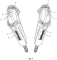
- the figure 2 represents posterior dorsal implantation by tubes, an example of which is illustrated in detail by the figure 3 .
- Each tube (1, 2) carries a screw implanted in the pedicles of two distinct vertebrae, not necessarily consecutive.
- the two tubes (1, 2) are offset along a sagittal axis parallel to the spine.
- the half-shells (11, 12), (21, 22) are open to each form an angle with respect to the sagittal plane. This opening makes it possible to clear the field of vision and work on the area of implantation of the corresponding screw.
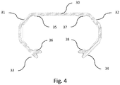
- the figure 4 is a detailed view of the connecting accessory.Il is constituted by a molded plastic part in the example described, having a general shape in "C".
- the middle part (30) has a length defining the opening angle of the tube, when the accessory is placed on the two half-shells.
- this median part (30) has a length of 25 millimeters, for an angulation of 20 degrees between the two half-shells (21, 22), when it has a length of 150 millimeters, measured between the connection area with the screw head on the one hand, and the connection area with the accessory on the other hand.
- the medial portion (30) is extended on either side by an arcuate portion (31, 32) whose inner section can fit into the outer surface of the distal end the distal ends (18, 19), (28, 29) half-shells (11, 12), (21, 22).
- the opening of these arcuate portions (31, 32) is determined to allow elastically deformable engagement on said distal ends (18, 19), (28, 29) of the half-shells (11, 12), (21, 22) ), and ensure a hold by clipping.
- Each arcuate portion (31, 32) is extended by a tab (33, 34) facilitating disassembly.
- These tabs (33, 34) make it possible to exert radial forces in order to open the arched part, when it is desired to remove the accessory.
- the inner surface of the accessory also has lugs (35 to 38) which are housed in complementary cavities provided on the inner surface of said distal ends (18, 19), (28, 29) of the half-shells (11, 12). ), (21, 22), and improve the positioning and maintenance of the accessory.
- the two half-tubes provide a lateral retractor function, when they are locked in the open position by the accessory according to the first embodiment, without it being necessary to introduce in the incision additional tooling.
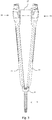
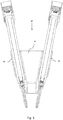
- the figure 5 represents a view along a sagittal sectional plane of a second embodiment, half-shells of two tubes connected by a second connecting accessory.
- This accessory is not used to connect the two half-shells of the same tube to exert a lateral pressure in a direction perpendicular to the sagittal plane, as provided for the first variant.
- It serves to connect two separate tubes, which may be one piece or two half-shells, and position a retractor accessory extending in a longitudinal direction.
- This accessory consists of a piece of plastic material (40) in the example described. It has a central zone (41) having the shape of a thin frustoconical segment, to form a curved web, extended on both sides by a gutter (42, 43) complementary shape to the outer section of said tubes.
- the two grooves (42, 43) have convergent axes in the proximal direction, with an angle of about 20 degrees.
- the inner surface of these gutters (42, 43) may have grooves (44) as shown in FIG. figure 6 to maintain the vertical position relative to the tubes (1, 2).
- Other clipping modes are conceivable, for example one or more studs, lugs or protuberances coming to engage in one or more complementary housing (s) provided (s) to the outer surface of the tubes (1, 2).
- These studs, lugs or protuberances are preferably configured to allow longitudinal movement of the tubes relative to the gutters, with indexed positions for example.
- the longitudinal displacement of the accessory relative to the tubes causes a variation of the spacing of the proximal ends of the tubes (1, 2) and consequently exerts a stress of separation of the screws anchored on the vertebrae on the one hand and the tubes (1, 2) on the other hand.
- This makes it possible to improve the vision on the intervertebral intervention zone, facilitating the surgical procedure, for example the greater the insertion of an interbody cage via the transforaminal route.
- Pushing the accessory in the proximal direction causes a forced opening of the space intervertebral.
- the figure 6 also shows that the central zone (41) has a first distal portion (45) in the form of a frustoconical tile of decreasing section towards the proximal direction, extended by a second cylindrical tile-shaped proximal portion (46), flared with respect to the first distal portion (45).
- the axis of symmetry of this second part forms a divergent angle with the axis of symmetry of the first part, so that the distal zone of the accessory pushes the tissues close to the vertebrae to the outside when it is engaged in the surgical area.
- the gutters may be replaced by lugs (47, 48) providing the same function of anchoring the accessory on the tubes (1, 2) as shown in FIG. figure 7 .
- the Figures 8 to 10 represent an alternative embodiment where the gutters (42, 43) are supported on the outer surfaces (49, 50) of the tubes (1, 2), on either side of the longitudinal tube (16, 26) of the tube (1, 2) associated.
- the central zone (40) forms a frustoconical web extending from one gutter (42) to the other (43), to create an opening of about 20 ° between the longitudinal axes of the two gutters (42, 43).
- This veil has a regular curvature, without sharp corners likely to hurt the spread tissues.
- the accessory When the accessory is in place, it releases an empty frustoconical interior volume (54) constituting a working area for the introduction of surgical instruments such as disc grippers or Kerisson forceps (trade name) or an interbody cage .
- the opening section of this frustoconical work area has a radius of about 40 millimeters, and is restricted to a radius of about 15 millimeters at the distal end. The length of this working area is between c and 100 mill
- a flange (55) extends in a plane substantially perpendicular to the central axis (56) of the accessory, over a width of about 10 millimeters. This flange (55) reinforces the part, and facilitates its handling.
- the web (41) has a flared cylindrical expansion (46).
- Each of the gutter (42, 43) has at its bearing surface on the tube (1, 2) a lug (57, 58) with a length of about 10 millimeters and a section corresponding to the opening of the lumen (16, 26) of the tubes (1, 2) and the U-shaped housing provided in the head of the spinal screws (7, 8).
- These lugs are housed in the screw heads when the accessory is pushed in the proximal direction. They thus ensure the locking and immobilization of the assembly via the insert or a plug inserted into the tube (1, 2).
- the figure 11 represents an example of implementation of a system using both types of accessories.
- the tubes (1, 2) are spaced apart from a longitudinal plane (53) in the open position, the half-shells (11, 12; 21, 22) being locked by first accessories (17, 27).
- the assembly defines a frustoconical work area (54).
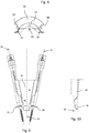
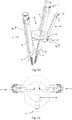
- the figure 12 is a perspective view of a third embodiment of two tubes connected by a third connecting accessory.
- the third connecting accessory 60 takes up most of the characteristics of the connection accessory illustrated on the figure 9 .
- it comprises a central zone (61) having the shape of a thin frustoconical segment to form a curved veil.
- the central zone (61) is extended on both sides by a gutter (62, 63) of complementary shape to the outer section of the tubes (1, 2). More particularly, the gutters (62, 63) are arranged diametrically opposite one another. They are further arranged to bear against the outer surface of the tubes (1, 2), on either side of the longitudinal lumen (16, 26) of the associated tube (1, 2) as illustrated in FIG. figure 12 .
- the third connecting accessory (60) comprises, at the proximal end, two lugs (67, 68) extending on either side of the central zone (61).
- Each lug (67, 68) has a section corresponding to the light opening (16, 26) of the tubes (1, 2) and the U-shaped housing provided in the head of the spinal screws (7, 8).
- lugs make it possible to lock and immobilize the tube and spinal screw assembly when the connecting accessory (60) is positioned on the tubes (1, 2), the lugs (7, 8) being arranged in the U-shape of the screw heads (7, 8).
- the median zone (61) is extended, at the distal end, by a semi-circular crown (64) extending from one gutter (62) to the other gutter (63).
- the semicircular ring (64) extends in a plane substantially perpendicular to the central axis (56) of the accessory. It delimits, with the distal end of the medial area (61) an entrance opening to a working area for the passage of surgical instruments or implants.
- the semicircular ring (64) is integrally formed with the medial area (61).
- the semicircular crown (64) has a through hole (66) for passage of a removable blade (65) from the distal end of the accessory to the proximal end.
- the through hole (66) is placed equidistantly to the two gutters (62, 63).
- the removable blade (65) delimits with the frustoconical web the working area.
- the removable blade (65) is an articulated blade.
- the removable blade (65) is locked on the semicircular ring (64) by means of a locking screw (67) mounted in a through hole formed on the outer face of the semi-cylindrical crown and opening into the through hole (66) of the removable blade (65). It is of course obvious that other means of blocking the blade can be provided without departing from the scope of the invention.
- the passage hole (66) has a funnel-shaped narrowing in a direction opposite to the distal end of the accessory 60.
- the outlet has a section slightly larger than the section of the removable blade. (65). This configuration thus makes it possible not only to facilitate the insertion of the blade (65) into the hole (66) but also to widen the working area by tilting said blade in the through hole (66) from a position in which the removable blade converges towards the proximal end of the frustoconical web to a substantially vertical position ( figure 14 ).
- the removable blade (65) comprises at the distal end gripping means 70.
- the gripping means is represented by a T-shaped (71).
Landscapes
- Health & Medical Sciences (AREA)
- Orthopedic Medicine & Surgery (AREA)
- Neurology (AREA)
- Life Sciences & Earth Sciences (AREA)
- Surgery (AREA)
- Heart & Thoracic Surgery (AREA)
- Engineering & Computer Science (AREA)
- Biomedical Technology (AREA)
- Nuclear Medicine, Radiotherapy & Molecular Imaging (AREA)
- Medical Informatics (AREA)
- Molecular Biology (AREA)
- Animal Behavior & Ethology (AREA)
- General Health & Medical Sciences (AREA)
- Public Health (AREA)
- Veterinary Medicine (AREA)
- Surgical Instruments (AREA)
- Prostheses (AREA)
Claims (11)
- Vorrichtung für den chirurgischen Eingriff an Wirbeln auf dem posterioren oder posterior-lateralen Weg, wobei die Vorrichtung folgendes umfasst:eine Einheit bestehend aus zwei Elementen, wobei jedes Element der Einheit eine Halbschale oder eine Röhre ist, die jeweils ein sogenanntes proximales Ende aufweist, welches in der Lage ist, mit einer Wirbelschraube und einem sogenannten distalen Ende zusammen zu wirken, undein Verbindungszubehörteil (17, 27, 40, 60), welches einen mittleren Teil (30, 41, 61) umfasst, der zu beiden Seiten durch einen Bereich für die reversible Befestigung auf jedem der Elemente der Einheit versehen ist, dadurch gekennzeichnet, dass die Befestigungsbereiche so mit dem mittleren Teil (30, 41, 61) angeordnet sind, dass sie die Elemente der Einheit zueinander in einer offenen Winkelposition halten, so dass jedes Element der Einheit das andere in proximale Richtung konvergiert.
- Vorrichtung für den Eingriff an der Wirbelsäule nach Anspruch 1, dadurch gekennzeichnet, dass die Befestigungsbereiche bogenförmige Partien umfassen, welche die Befestigungsschienen, deren Achsen in proximale Richtung zueinander konvergieren, abgrenzen.
- Vorrichtung für den Eingriff an der Wirbelsäule nach Anspruch 1 oder Anspruch 2, dadurch gekennzeichnet, dass die Röhren (1, 2), welche die Elemente der Einheit bilden, jeweils durch zwei Halbschalen (11, 12; 21, 22) gebildet werden, die in der Lage sind, mit dem Kopf einer Wirbelschraube zusammen zu wirken, so dass das proximale Kippen mindestens einer der Halbschalen (11, 12, 21,22) in Bezug auf den Kopf besagter Wirbelschraube (5, 6) möglich ist, wobei besagtes Verbindungzubehörteil (17, 27, 40) so gestaltet ist, dass zwei der besagten Halbschalen (11, 12, 21, 22) besagter Röhren in einer offenen winkelförmigen Ausrichtung gehalten werden.
- Vorrichtung für den Eingriff an der Wirbelsäule gemäß einem der Ansprüche 1 bis 3, dadurch gekennzeichnet, dass besagtes Verbindungszubehörteil (17, 27) aus einem Teil besteht, das an besagte Elemente der Einheit angepasst werden kann, wobei besagtes Teil (17, 27) einen mittleren Teil (30) aufweist, der zu beiden Seiten durch einen Bereich für eine reversible Befestigung (31, 32) verlängert wird, welcher in der Lage ist, mit einem distalen ergänzenden Bereich einer der besagten Halbschalen zusammen zu wirken, um besagte Halbschalen in offener Position zu verriegeln.
- Vorrichtung für den Eingriff an der Wirbelsäule gemäß einem der Ansprüche 1 bis 4, dadurch gekennzeichnet, dass die Befestigungsbereiche (31, 32) eine Innenfläche aufweisen, welche die Außenfläche des vorderen Bereichs der Elemente der Einheit, auf welcher die Befestigungsbereiche befestigt werden, ergänzt.
- Vorrichtung für den Eingriff an der Wirbelsäule nach einem der Ansprüche 1 bis 5, dadurch gekennzeichnet, dass wenn die Elemente der Einheit Röhren sind, besagtes Verbindungszubehörteil aus einer steifen Einzugsfeder (40) besteht, die in der Lage ist, mit besagten einzelnen Röhren (1, 2) zusammen zu wirken und das Gewebe im Operationsbereich durch die Verriegelung der Ausrichtung in Bezug auf besagte Röhren (1, 2) gespreizt zu halten.
- Vorrichtung für den Eingriff an der Wirbelsäule nach Anspruch 6, dadurch gekennzeichnet, dass der mittlere Teil (41) der Einzugsfeder (40) die Form eines dünnen konusförmigen Abschnitts hat, um einen gewölbten Beschlag zu bilden, der zu beiden Seiten durch eine Schiene (42,43) in einer den äußeren Abschnitt besagter Röhre ergänzenden Form verlängert wird, wobei besagte Schienen (42, 43) die Bereiche der reversiblen Befestigung des Verbindungszubehörteils bilden.
- Vorrichtung für den Eingriff an der Wirbelsäule nach Anspruch 7, dadurch gekennzeichnet, dass die Schienen so angeordnet sind, dass sie eine relative Längsverschiebung der in besagten Schienen (42,43) liegenden Röhren (1, 2) ermöglichen.
- Vorrichtung für den Eingriff an der Wirbelsäule nach einem der Ansprüche 1 bis 8, dadurch gekennzeichnet, dass wenn die Elemente der Einheit Röhren sind, das Verbindungszubehörteil (40, 60) am proximalen Ende Stifte (57, 58, 67, 68) aufweist, welche die Verriegelung und das Blockieren der Röhren auf den Wirbelschrauben gewährleisten, wenn letztere auf die Wirbelschrauben (7, 8) montiert werden und wenn das Verbindungszubehörteil (60) auf den Röhren (1, 2) positioniert wird, wobei sich besagte Stifte (57, 58, 67, 68) zu beiden Seiten des mittleren Bereichs (41, 61) erstrecken und einen Abschnitt aufweisen, der der u-förmigen Aufnahme des Kopfes der Wirbelschraube (7, 8) entspricht.
- Vorrichtung für den Eingriff an der Wirbelsäule nach mindestens einen der Ansprüche 1 bis 9, dadurch gekennzeichnet, dass sie zwei Röhren (1, 2) umfasst, welche jeweils aus zwei Halbschalen (11, 12, 21, 22), zwei Wirbelschrauben (5, 6) und zwei Verbindungszubehörteilen gebildet werden.
- Vorrichtung für den Eingriff an der Wirbelsäule nach Anspruch 7 oder Anspruch 8, dadurch gekennzeichnet, dass der mittlere Bereich (41) einen ersten distalen Teil (45) in Form eines konusförmigen Formteils aufweist, deren Querschnitt in proximale Richtung kleiner wird, die durch einen zweiten proximalen Teil (46) in Form eines zylindrischen Formteils, welches in Bezug auf den ersten distalen Teil (45) ausgestellt ist, verlängert wird.
Applications Claiming Priority (2)
| Application Number | Priority Date | Filing Date | Title |
|---|---|---|---|
| FR1254895A FR2990839B1 (fr) | 2012-05-28 | 2012-05-28 | Dispositif rachidien comprenant des moyens d’accroche reversible |
| PCT/FR2013/051191 WO2013178940A1 (fr) | 2012-05-28 | 2013-05-28 | Dispositif rachidien comprenant des moyens d'accroche réversible |
Publications (2)
| Publication Number | Publication Date |
|---|---|
| EP2854673A1 EP2854673A1 (de) | 2015-04-08 |
| EP2854673B1 true EP2854673B1 (de) | 2018-03-07 |
Family
ID=48656231
Family Applications (1)
| Application Number | Title | Priority Date | Filing Date |
|---|---|---|---|
| EP13729998.8A Not-in-force EP2854673B1 (de) | 2012-05-28 | 2013-05-28 | Wirbelsäulenvorrichtung mit mittel zur reversiblen befestigung |
Country Status (5)
| Country | Link |
|---|---|
| US (1) | US10201341B2 (de) |
| EP (1) | EP2854673B1 (de) |
| ES (1) | ES2671630T3 (de) |
| FR (1) | FR2990839B1 (de) |
| WO (1) | WO2013178940A1 (de) |
Families Citing this family (6)
| Publication number | Priority date | Publication date | Assignee | Title |
|---|---|---|---|---|
| FR2988582B1 (fr) * | 2012-04-02 | 2014-03-14 | Safe Orthopaedics | Kit d'instrumentation |
| US9402661B2 (en) * | 2013-09-23 | 2016-08-02 | Stryker European Holdings I, LCC | Lumbar-sacral screw insertion and manipulation |
| US9622795B2 (en) * | 2013-12-13 | 2017-04-18 | Stryker European Holdings I, Llc | Tissue retraction and vertebral displacement devices, systems, and methods for posterior spinal fusion |
| FR3018678B1 (fr) * | 2014-03-20 | 2016-03-11 | Spineway | Ensemble chirurgical, vis d'ancrage osseux et dispositif d'extension d'une telle vis faisant parties dudit ensemble chirurgical |
| JP6475449B2 (ja) * | 2014-09-18 | 2019-02-27 | 賢 石井 | 脊椎手術用器具 |
| US10278687B2 (en) * | 2015-08-18 | 2019-05-07 | Globus Medical, Inc. | Devices and systems for surgical retraction |
Family Cites Families (8)
| Publication number | Priority date | Publication date | Assignee | Title |
|---|---|---|---|---|
| US3509873A (en) | 1967-04-24 | 1970-05-05 | Jack B Karlin | Retractor |
| IT1239524B (it) | 1990-04-03 | 1993-11-05 | Giuseppe Amato | Divaricatore chirurgico in particolare per colecistectomia |
| US8002798B2 (en) * | 2003-09-24 | 2011-08-23 | Stryker Spine | System and method for spinal implant placement |
| FR2874496B1 (fr) | 2004-09-02 | 2006-11-24 | Spinevision Sa | Retracteur de tissus permettant l'obtention d'un canal operatoire elargi |
| US8109934B2 (en) * | 2005-02-10 | 2012-02-07 | Zimmer Spine, Inc. | All through one drill guide for cervical plating |
| WO2008131084A2 (en) * | 2007-04-17 | 2008-10-30 | K2M, Inc. | Minimally open interbody access retraction device and surgical method |
| US8727972B2 (en) * | 2009-02-03 | 2014-05-20 | Warsaw Orthopedic, Inc. | Low profile bone screw extender and its application in minimum invasive spinal surgeries |
| FR2954689B1 (fr) * | 2009-12-28 | 2012-12-21 | Sterispine | Dispositif et methode pour la chirurgie rachidienne. |
-
2012
- 2012-05-28 FR FR1254895A patent/FR2990839B1/fr not_active Expired - Fee Related
-
2013
- 2013-05-28 ES ES13729998.8T patent/ES2671630T3/es active Active
- 2013-05-28 WO PCT/FR2013/051191 patent/WO2013178940A1/fr not_active Ceased
- 2013-05-28 EP EP13729998.8A patent/EP2854673B1/de not_active Not-in-force
- 2013-05-28 US US14/402,444 patent/US10201341B2/en active Active
Also Published As
| Publication number | Publication date |
|---|---|
| ES2671630T3 (es) | 2018-06-07 |
| US20150164495A1 (en) | 2015-06-18 |
| EP2854673A1 (de) | 2015-04-08 |
| FR2990839B1 (fr) | 2015-03-06 |
| FR2990839A1 (fr) | 2013-11-29 |
| US10201341B2 (en) | 2019-02-12 |
| WO2013178940A1 (fr) | 2013-12-05 |
Similar Documents
| Publication | Publication Date | Title |
|---|---|---|
| EP2854674B1 (de) | Instrumentensystem zur durchführung eines chirurgischen eingriffs an wirbeln mit einer temporären immobilisierungmitteln | |
| EP2854673B1 (de) | Wirbelsäulenvorrichtung mit mittel zur reversiblen befestigung | |
| EP2526888B1 (de) | Vorrichtung für die Wirbelchirurgie | |
| EP1872731B1 (de) | Implantat zur Stabilisierung der Lumbosakralregion | |
| FR2722088A1 (fr) | Implant chirurgical de stabilisation de l'espace intervertebral | |
| WO2013150252A1 (fr) | Instrument et systeme chirurgical pour la fixation des vertebres | |
| FR2651992A1 (fr) | Implant pour osteosynthese rachidienne dorso-lombaire anterieure destine a la correction de cyphoses. | |
| FR2926457A1 (fr) | Cage intervertebrale et dispositif de fusion vertebrale la comportant | |
| EP1075224A1 (de) | Wirbelsäulen-osteosynthesesystem mit spannvorrichtung, insbesondere zur vorderen fixierung | |
| EP3119298B1 (de) | Chirurgische anordnung und knochenankerschraube und vorrichtung zur erweiterung solch einer schraube, die zur besagten chirurgischen anordnung gehört | |
| WO2011080404A1 (fr) | Equipement pour la pose d'un implant | |
| FR2959113A1 (fr) | Vis pediculaire polaxiale et dispositif de fixation pediculaire en faisant application, pour osteosynthese vertebrale | |
| FR2807313A1 (fr) | Ensemble retracteur orthopedique de tissus mous notamment pour la chirurgie du rachis | |
| WO2013150232A1 (fr) | Kit d'intrumentation d'osteosynthèse rachidienne | |
| EP2953564B1 (de) | Implantationsanordnung mit einem auf einem knochenimplantat vormontierten treiberelement | |
| FR3036031A1 (fr) | Implant pour la fixation d'elements osseux | |
| WO2018024617A1 (fr) | Implant deployable | |
| EP2288304A2 (de) | Element als verbindung zwischen einem längselement einer vertebralen osteosynthese-vorrichtung und einem wirbel, dieses umfassende vertebrale osteosynthese-vorrichtung und werkzeug zu seiner anbringung | |
| FR3047658A1 (fr) | Implant intervertebral de stabilisation dynamique et son outil de positionnement | |
| FR3049852A1 (fr) | Implant de fusion intervertebrale a implanter par voie anterieure | |
| EP3493772A1 (de) | Gekrümmte stift zur fixierung von knochen | |
| FR2929829A1 (fr) | Systeme de liaison entre un implant remplacant un corps vertebral et une instrumentation de fixation |
Legal Events
| Date | Code | Title | Description |
|---|---|---|---|
| PUAI | Public reference made under article 153(3) epc to a published international application that has entered the european phase |
Free format text: ORIGINAL CODE: 0009012 |
|
| 17P | Request for examination filed |
Effective date: 20141114 |
|
| AK | Designated contracting states |
Kind code of ref document: A1 Designated state(s): AL AT BE BG CH CY CZ DE DK EE ES FI FR GB GR HR HU IE IS IT LI LT LU LV MC MK MT NL NO PL PT RO RS SE SI SK SM TR |
|
| AX | Request for extension of the european patent |
Extension state: BA ME |
|
| DAX | Request for extension of the european patent (deleted) | ||
| 17Q | First examination report despatched |
Effective date: 20151103 |
|
| GRAP | Despatch of communication of intention to grant a patent |
Free format text: ORIGINAL CODE: EPIDOSNIGR1 |
|
| INTG | Intention to grant announced |
Effective date: 20171002 |
|
| GRAS | Grant fee paid |
Free format text: ORIGINAL CODE: EPIDOSNIGR3 |
|
| GRAA | (expected) grant |
Free format text: ORIGINAL CODE: 0009210 |
|
| AK | Designated contracting states |
Kind code of ref document: B1 Designated state(s): AL AT BE BG CH CY CZ DE DK EE ES FI FR GB GR HR HU IE IS IT LI LT LU LV MC MK MT NL NO PL PT RO RS SE SI SK SM TR |
|
| REG | Reference to a national code |
Ref country code: GB Ref legal event code: FG4D Free format text: NOT ENGLISH |
|
| REG | Reference to a national code |
Ref country code: CH Ref legal event code: EP Ref country code: AT Ref legal event code: REF Ref document number: 975687 Country of ref document: AT Kind code of ref document: T Effective date: 20180315 |
|
| REG | Reference to a national code |
Ref country code: IE Ref legal event code: FG4D Free format text: LANGUAGE OF EP DOCUMENT: FRENCH |
|
| REG | Reference to a national code |
Ref country code: DE Ref legal event code: R096 Ref document number: 602013034022 Country of ref document: DE |
|
| REG | Reference to a national code |
Ref country code: CH Ref legal event code: NV Representative=s name: ABREMA AGENCE BREVET ET MARQUES, GANGUILLET, CH |
|
| REG | Reference to a national code |
Ref country code: FR Ref legal event code: PLFP Year of fee payment: 6 |
|
| REG | Reference to a national code |
Ref country code: ES Ref legal event code: FG2A Ref document number: 2671630 Country of ref document: ES Kind code of ref document: T3 Effective date: 20180607 |
|
| REG | Reference to a national code |
Ref country code: NL Ref legal event code: MP Effective date: 20180307 |
|
| REG | Reference to a national code |
Ref country code: LT Ref legal event code: MG4D |
|
| PG25 | Lapsed in a contracting state [announced via postgrant information from national office to epo] |
Ref country code: NO Free format text: LAPSE BECAUSE OF FAILURE TO SUBMIT A TRANSLATION OF THE DESCRIPTION OR TO PAY THE FEE WITHIN THE PRESCRIBED TIME-LIMIT Effective date: 20180607 Ref country code: FI Free format text: LAPSE BECAUSE OF FAILURE TO SUBMIT A TRANSLATION OF THE DESCRIPTION OR TO PAY THE FEE WITHIN THE PRESCRIBED TIME-LIMIT Effective date: 20180307 Ref country code: LT Free format text: LAPSE BECAUSE OF FAILURE TO SUBMIT A TRANSLATION OF THE DESCRIPTION OR TO PAY THE FEE WITHIN THE PRESCRIBED TIME-LIMIT Effective date: 20180307 Ref country code: CY Free format text: LAPSE BECAUSE OF FAILURE TO SUBMIT A TRANSLATION OF THE DESCRIPTION OR TO PAY THE FEE WITHIN THE PRESCRIBED TIME-LIMIT Effective date: 20180307 Ref country code: HR Free format text: LAPSE BECAUSE OF FAILURE TO SUBMIT A TRANSLATION OF THE DESCRIPTION OR TO PAY THE FEE WITHIN THE PRESCRIBED TIME-LIMIT Effective date: 20180307 |
|
| REG | Reference to a national code |
Ref country code: AT Ref legal event code: MK05 Ref document number: 975687 Country of ref document: AT Kind code of ref document: T Effective date: 20180307 |
|
| PG25 | Lapsed in a contracting state [announced via postgrant information from national office to epo] |
Ref country code: GR Free format text: LAPSE BECAUSE OF FAILURE TO SUBMIT A TRANSLATION OF THE DESCRIPTION OR TO PAY THE FEE WITHIN THE PRESCRIBED TIME-LIMIT Effective date: 20180608 Ref country code: RS Free format text: LAPSE BECAUSE OF FAILURE TO SUBMIT A TRANSLATION OF THE DESCRIPTION OR TO PAY THE FEE WITHIN THE PRESCRIBED TIME-LIMIT Effective date: 20180307 Ref country code: BG Free format text: LAPSE BECAUSE OF FAILURE TO SUBMIT A TRANSLATION OF THE DESCRIPTION OR TO PAY THE FEE WITHIN THE PRESCRIBED TIME-LIMIT Effective date: 20180607 Ref country code: LV Free format text: LAPSE BECAUSE OF FAILURE TO SUBMIT A TRANSLATION OF THE DESCRIPTION OR TO PAY THE FEE WITHIN THE PRESCRIBED TIME-LIMIT Effective date: 20180307 Ref country code: SE Free format text: LAPSE BECAUSE OF FAILURE TO SUBMIT A TRANSLATION OF THE DESCRIPTION OR TO PAY THE FEE WITHIN THE PRESCRIBED TIME-LIMIT Effective date: 20180307 |
|
| PG25 | Lapsed in a contracting state [announced via postgrant information from national office to epo] |
Ref country code: MT Free format text: LAPSE BECAUSE OF FAILURE TO SUBMIT A TRANSLATION OF THE DESCRIPTION OR TO PAY THE FEE WITHIN THE PRESCRIBED TIME-LIMIT Effective date: 20180307 |
|
| PG25 | Lapsed in a contracting state [announced via postgrant information from national office to epo] |
Ref country code: NL Free format text: LAPSE BECAUSE OF FAILURE TO SUBMIT A TRANSLATION OF THE DESCRIPTION OR TO PAY THE FEE WITHIN THE PRESCRIBED TIME-LIMIT Effective date: 20180307 Ref country code: AL Free format text: LAPSE BECAUSE OF FAILURE TO SUBMIT A TRANSLATION OF THE DESCRIPTION OR TO PAY THE FEE WITHIN THE PRESCRIBED TIME-LIMIT Effective date: 20180307 Ref country code: PL Free format text: LAPSE BECAUSE OF FAILURE TO SUBMIT A TRANSLATION OF THE DESCRIPTION OR TO PAY THE FEE WITHIN THE PRESCRIBED TIME-LIMIT Effective date: 20180307 Ref country code: RO Free format text: LAPSE BECAUSE OF FAILURE TO SUBMIT A TRANSLATION OF THE DESCRIPTION OR TO PAY THE FEE WITHIN THE PRESCRIBED TIME-LIMIT Effective date: 20180307 Ref country code: EE Free format text: LAPSE BECAUSE OF FAILURE TO SUBMIT A TRANSLATION OF THE DESCRIPTION OR TO PAY THE FEE WITHIN THE PRESCRIBED TIME-LIMIT Effective date: 20180307 |
|
| PG25 | Lapsed in a contracting state [announced via postgrant information from national office to epo] |
Ref country code: SK Free format text: LAPSE BECAUSE OF FAILURE TO SUBMIT A TRANSLATION OF THE DESCRIPTION OR TO PAY THE FEE WITHIN THE PRESCRIBED TIME-LIMIT Effective date: 20180307 Ref country code: CZ Free format text: LAPSE BECAUSE OF FAILURE TO SUBMIT A TRANSLATION OF THE DESCRIPTION OR TO PAY THE FEE WITHIN THE PRESCRIBED TIME-LIMIT Effective date: 20180307 Ref country code: SM Free format text: LAPSE BECAUSE OF FAILURE TO SUBMIT A TRANSLATION OF THE DESCRIPTION OR TO PAY THE FEE WITHIN THE PRESCRIBED TIME-LIMIT Effective date: 20180307 Ref country code: AT Free format text: LAPSE BECAUSE OF FAILURE TO SUBMIT A TRANSLATION OF THE DESCRIPTION OR TO PAY THE FEE WITHIN THE PRESCRIBED TIME-LIMIT Effective date: 20180307 |
|
| REG | Reference to a national code |
Ref country code: DE Ref legal event code: R097 Ref document number: 602013034022 Country of ref document: DE |
|
| PG25 | Lapsed in a contracting state [announced via postgrant information from national office to epo] |
Ref country code: PT Free format text: LAPSE BECAUSE OF FAILURE TO SUBMIT A TRANSLATION OF THE DESCRIPTION OR TO PAY THE FEE WITHIN THE PRESCRIBED TIME-LIMIT Effective date: 20180709 |
|
| PLBE | No opposition filed within time limit |
Free format text: ORIGINAL CODE: 0009261 |
|
| STAA | Information on the status of an ep patent application or granted ep patent |
Free format text: STATUS: NO OPPOSITION FILED WITHIN TIME LIMIT |
|
| REG | Reference to a national code |
Ref country code: BE Ref legal event code: MM Effective date: 20180531 |
|
| PG25 | Lapsed in a contracting state [announced via postgrant information from national office to epo] |
Ref country code: MC Free format text: LAPSE BECAUSE OF FAILURE TO SUBMIT A TRANSLATION OF THE DESCRIPTION OR TO PAY THE FEE WITHIN THE PRESCRIBED TIME-LIMIT Effective date: 20180307 Ref country code: DK Free format text: LAPSE BECAUSE OF FAILURE TO SUBMIT A TRANSLATION OF THE DESCRIPTION OR TO PAY THE FEE WITHIN THE PRESCRIBED TIME-LIMIT Effective date: 20180307 |
|
| 26N | No opposition filed |
Effective date: 20181210 |
|
| REG | Reference to a national code |
Ref country code: IE Ref legal event code: MM4A |
|
| PG25 | Lapsed in a contracting state [announced via postgrant information from national office to epo] |
Ref country code: SI Free format text: LAPSE BECAUSE OF FAILURE TO SUBMIT A TRANSLATION OF THE DESCRIPTION OR TO PAY THE FEE WITHIN THE PRESCRIBED TIME-LIMIT Effective date: 20180307 |
|
| PG25 | Lapsed in a contracting state [announced via postgrant information from national office to epo] |
Ref country code: LU Free format text: LAPSE BECAUSE OF NON-PAYMENT OF DUE FEES Effective date: 20180528 |
|
| PG25 | Lapsed in a contracting state [announced via postgrant information from national office to epo] |
Ref country code: IE Free format text: LAPSE BECAUSE OF NON-PAYMENT OF DUE FEES Effective date: 20180528 |
|
| PG25 | Lapsed in a contracting state [announced via postgrant information from national office to epo] |
Ref country code: BE Free format text: LAPSE BECAUSE OF NON-PAYMENT OF DUE FEES Effective date: 20180531 |
|
| PG25 | Lapsed in a contracting state [announced via postgrant information from national office to epo] |
Ref country code: TR Free format text: LAPSE BECAUSE OF FAILURE TO SUBMIT A TRANSLATION OF THE DESCRIPTION OR TO PAY THE FEE WITHIN THE PRESCRIBED TIME-LIMIT Effective date: 20180307 |
|
| PG25 | Lapsed in a contracting state [announced via postgrant information from national office to epo] |
Ref country code: HU Free format text: LAPSE BECAUSE OF FAILURE TO SUBMIT A TRANSLATION OF THE DESCRIPTION OR TO PAY THE FEE WITHIN THE PRESCRIBED TIME-LIMIT; INVALID AB INITIO Effective date: 20130528 |
|
| PG25 | Lapsed in a contracting state [announced via postgrant information from national office to epo] |
Ref country code: MK Free format text: LAPSE BECAUSE OF NON-PAYMENT OF DUE FEES Effective date: 20180307 |
|
| PG25 | Lapsed in a contracting state [announced via postgrant information from national office to epo] |
Ref country code: IS Free format text: LAPSE BECAUSE OF FAILURE TO SUBMIT A TRANSLATION OF THE DESCRIPTION OR TO PAY THE FEE WITHIN THE PRESCRIBED TIME-LIMIT Effective date: 20180707 |
|
| REG | Reference to a national code |
Ref country code: CH Ref legal event code: PFUS Owner name: SAFE ORTHOPAEDICS, FR Free format text: FORMER OWNER: SAFE ORTHOPAEDICS, FR |
|
| PGFP | Annual fee paid to national office [announced via postgrant information from national office to epo] |
Ref country code: IT Payment date: 20220524 Year of fee payment: 10 Ref country code: GB Payment date: 20220520 Year of fee payment: 10 Ref country code: FR Payment date: 20220523 Year of fee payment: 10 Ref country code: DE Payment date: 20220519 Year of fee payment: 10 |
|
| PGFP | Annual fee paid to national office [announced via postgrant information from national office to epo] |
Ref country code: CH Payment date: 20220519 Year of fee payment: 10 |
|
| PGFP | Annual fee paid to national office [announced via postgrant information from national office to epo] |
Ref country code: ES Payment date: 20220725 Year of fee payment: 10 |
|
| REG | Reference to a national code |
Ref country code: DE Ref legal event code: R119 Ref document number: 602013034022 Country of ref document: DE |
|
| REG | Reference to a national code |
Ref country code: CH Ref legal event code: PL |
|
| GBPC | Gb: european patent ceased through non-payment of renewal fee |
Effective date: 20230528 |
|
| PG25 | Lapsed in a contracting state [announced via postgrant information from national office to epo] |
Ref country code: LI Free format text: LAPSE BECAUSE OF NON-PAYMENT OF DUE FEES Effective date: 20230531 Ref country code: CH Free format text: LAPSE BECAUSE OF NON-PAYMENT OF DUE FEES Effective date: 20230531 |
|
| PG25 | Lapsed in a contracting state [announced via postgrant information from national office to epo] |
Ref country code: IT Free format text: LAPSE BECAUSE OF NON-PAYMENT OF DUE FEES Effective date: 20230528 Ref country code: DE Free format text: LAPSE BECAUSE OF NON-PAYMENT OF DUE FEES Effective date: 20231201 Ref country code: GB Free format text: LAPSE BECAUSE OF NON-PAYMENT OF DUE FEES Effective date: 20230528 |
|
| PG25 | Lapsed in a contracting state [announced via postgrant information from national office to epo] |
Ref country code: FR Free format text: LAPSE BECAUSE OF NON-PAYMENT OF DUE FEES Effective date: 20230531 |
|
| REG | Reference to a national code |
Ref country code: ES Ref legal event code: FD2A Effective date: 20240704 |
|
| PG25 | Lapsed in a contracting state [announced via postgrant information from national office to epo] |
Ref country code: ES Free format text: LAPSE BECAUSE OF NON-PAYMENT OF DUE FEES Effective date: 20230529 |
|
| PG25 | Lapsed in a contracting state [announced via postgrant information from national office to epo] |
Ref country code: ES Free format text: LAPSE BECAUSE OF NON-PAYMENT OF DUE FEES Effective date: 20230529 |