EP2526752B1 - Erntevorrichtung - Google Patents
Erntevorrichtung Download PDFInfo
- Publication number
- EP2526752B1 EP2526752B1 EP12157628.4A EP12157628A EP2526752B1 EP 2526752 B1 EP2526752 B1 EP 2526752B1 EP 12157628 A EP12157628 A EP 12157628A EP 2526752 B1 EP2526752 B1 EP 2526752B1
- Authority
- EP
- European Patent Office
- Prior art keywords
- collecting container
- combine harvester
- harvesting
- conveyor
- grain tank
- Prior art date
- Legal status (The legal status is an assumption and is not a legal conclusion. Google has not performed a legal analysis and makes no representation as to the accuracy of the status listed.)
- Active
Links
Images

Classifications
-
- B—PERFORMING OPERATIONS; TRANSPORTING
- B65—CONVEYING; PACKING; STORING; HANDLING THIN OR FILAMENTARY MATERIAL
- B65G—TRANSPORT OR STORAGE DEVICES, e.g. CONVEYORS FOR LOADING OR TIPPING, SHOP CONVEYOR SYSTEMS OR PNEUMATIC TUBE CONVEYORS
- B65G67/00—Loading or unloading vehicles
- B65G67/02—Loading or unloading land vehicles
- B65G67/04—Loading land vehicles
- B65G67/22—Loading moving vehicles
-
- A—HUMAN NECESSITIES
- A01—AGRICULTURE; FORESTRY; ANIMAL HUSBANDRY; HUNTING; TRAPPING; FISHING
- A01B—SOIL WORKING IN AGRICULTURE OR FORESTRY; PARTS, DETAILS, OR ACCESSORIES OF AGRICULTURAL MACHINES OR IMPLEMENTS, IN GENERAL
- A01B69/00—Steering of agricultural machines or implements; Guiding agricultural machines or implements on a desired track
- A01B69/007—Steering or guiding of agricultural vehicles, e.g. steering of the tractor to keep the plough in the furrow
- A01B69/008—Steering or guiding of agricultural vehicles, e.g. steering of the tractor to keep the plough in the furrow automatic
-
- A—HUMAN NECESSITIES
- A01—AGRICULTURE; FORESTRY; ANIMAL HUSBANDRY; HUNTING; TRAPPING; FISHING
- A01D—HARVESTING; MOWING
- A01D43/00—Mowers combined with apparatus performing additional operations while mowing
- A01D43/06—Mowers combined with apparatus performing additional operations while mowing with means for collecting, gathering or loading mown material
- A01D43/07—Mowers combined with apparatus performing additional operations while mowing with means for collecting, gathering or loading mown material in or into a trailer
- A01D43/073—Mowers combined with apparatus performing additional operations while mowing with means for collecting, gathering or loading mown material in or into a trailer with controllable discharge spout
Definitions
- the invention relates to a harvesting device, essentially consisting of a self-propelled harvester and provided with a drive unit mobile collecting container which is positionable relative to the harvester and movable parallel to this and the harvesting operation via a provided with an outlet pipe conveyor a crop from the harvester can be fed from directly or indirectly, with a device for uniform loading of this collection container.
- the invention according to the preamble of independent claim 15 relates to a method for removing a stored in a grain tank of a self-propelled combine crop in a provided with a drive unit mobile collecting container, wherein the collecting container is positioned relative to the combine and moved parallel to this and the crop is fed to the collection container directly or indirectly at the same time with the harvesting operation via a provided with a discharge spout grain tank outlet pipe.
- harvesters designed as combine harvesters or forage harvesters were generally not equipped with their own propulsion, but were pulled by an agricultural tractor and propelled by its PTO shaft. Meanwhile, almost all combine harvesters used in the grain, canola or corn harvest are self-propelled harvesters. High-performance forage harvesters, which are used by large companies or contractors, also have their own drive unit as a self-propelled harvester.
- the collecting container which may also be self-propelled or movable by means of a tractor occupies a position adjacent to the combine, in which the crop via a with a Outlet neck provided delivery pipe is conveyed into the sump.
- the driver for example, during the grain harvest, should focus primarily on the mowing and threshing, so the view of the header plays an important role. But if he also has to monitor the position of the collection container and the Abtankvorgang, but he is too distracted from this main task. In addition, for him often the view of the sump is limited by a strong dust during the threshing and the Abtankvorganges, so that there are virtually no opportunities for him to monitor the supply of the crop in the sump hundred percent.
- a harvesting device with a self-propelled harvester and a drive unit having mobile collecting container referred to in the preamble of claim 1 genus is from the EP 2 245 916 A1 known.
- the moving of a tractor parallel to the harvester collecting tank should be evenly loaded by each change the position of the collecting container relative to the outlet nozzle of the conveyor tube in the direction of travel.
- This change in the relative position of the collection container relative to the harvester and the maintenance of a parallel lane should be achieved by a GPS system.
- the outlet nozzle is designed to be pivotable relative to the conveyor pipe and is adjusted via the automatic control system such that the emerging crop selectively passes into the collecting container while avoiding grain losses.
- the supply of the crop should be made possible in the collection under all harvest conditions.
- the collecting container is to be moved during the conveying of the crop by means of a control device in a constant relative position to the harvester, and the collecting container should have a filling device, by means of a uniform distribution of the crop in the collecting tank can be achieved. Consequently, the function of the distribution of the crop within the collecting container is achieved solely by means of the filling device according to the invention, which is provided on the collecting container.
- the collecting container moved parallel to the harvesting machine maintains a constant safety distance with respect to the harvesting machine and is advanced at a speed which corresponds to the speed of the harvesting machine.
- the harvester is to be designed as a self-propelled combine harvester, wherein the feed pipe designed as a grain tank headbox pipe emanates from a grain tank of the combine harvester.
- the level of the grain tank of the combine harvester which serves as a buffer store, is determined monitored continuously, and it is automatically requested before reaching a maximum level of a combine harvester positioned next collecting container.
- the collecting container is brought by a designed as a tractor tractors in the position for a subsequent unloading of the crop.
- the start-up of the combine harvester in harvesting operation by the respective collection container can also be done manually first, whereupon the control device but then bring the sump in its intended for the Abtankvorgang position and maintain this positioning relative to the moving combine harvester.
- both the harvester designed as a harvester and the drive unit of the mobile collecting container may be provided with a navigation system, held by both during the promotion of the crop in a constant relative position to each other become.
- a navigation system held by both during the promotion of the crop in a constant relative position to each other become.
- it will preferably be a solution based on GPS signals and radio systems, via which a so-called “electronic drawbar" can be produced.
- a supplementary system may be provided which maintains the positioning of the vehicles to each other when the GPS or radio transmission is disturbed.
- the two vehicle positions are additionally monitored and consequently the position of the collecting container can be corrected.
- These distance sensors would make an adjustment of the speed and steering angle corrections to the drive unit of the sump.
- arranged on a combine harvester header should have such a lateral extent that this header overhangs the combine harvester on both sides, in which case the collecting container occupies a position substantially within the extension of the header during the promotion of the crop on the grain tank outlet pipe.
- the grain tank outlet pipe is usually on combine harvesters, seen in the direction of travel on the left side provided. Accordingly, during a Abtankvorgangs the preferably pulled by a tractor hopper would move within this lateral extension of the header.
- combine harvesters are provided with a chopper arranged at the straw and chaff outlet, which ensures sufficient comminution and distribution of these components. so that they can be incorporated evenly during the subsequent tillage in the upper soil layer to be incorporated to achieve an optimal Bodengare.
- the combine harvester is to have a corresponding shredder with an adjustable guide for adjusting the width of a straw and chaff distribution, the guide is automatically moved due to a signal transmitted from the collecting container in a position in which the width of the distribution is reduced on one side such that it lies outside a tramline of the collection container.
- the corresponding control devices the chopper which are preferably hydraulically adjustable, thus take an asymmetric distribution of the crushed straw and the chaff.
- This adjustment of the guiding device of the chopper which preferably takes place automatically, is then used when the mobile collecting container is moved into its position next to the combine harvester. After draining the grain tank and removing the sump, the baffle is returned to its normal spreading function so that straw and chaff are again distributed over the entire working width of the combine. In this way it is prevented that the shredded material collects on the transport container and thus form accumulations or a swath of shredded material.
- the filling device of the collecting container should have at least one longitudinal conveyor acting in the longitudinal direction of the collecting container.
- This longitudinal conveyor transports the harvested material supplied to the collecting container in such a way that a uniform distribution of the crop in the collecting container can be achieved until it reaches its maximum filling volume.
- the longitudinal conveyor may be formed as at least one screw conveyor or as a chain conveyor. However, they may also be other types of longitudinal conveyors that continuously or at intervals make a distribution of the crop.
- the longitudinal conveyor can be arranged in a conveyor trough, wherein different outlet regions with different outlet cross sections can be set on the conveyor trough.
- These adjustable outlet cross sections or alternatively guide elements ensure a uniform distribution of the crop, and they can be monitored by measuring devices that monitor the level in the sump or depending on other parameters. For example, the Adjustment function are affected when the combine harvester is lowered in a slope on a slope, so that this can not lead to a one-sided loading of the collecting container.
- the supply of the crop via the outlet nozzle of the grain tank outlet pipe can be carried out centrally, based on the longitudinal extent of the collecting container.
- the filling device has at least two longitudinal conveyors acting in opposite conveying directions.
- the feed of the crop can also take place at one end of the collecting container, in which case at least one longitudinal conveyor acting in a conveying direction is provided.
- the collecting container should have at one of its ends its loading hopper, from which the at least one longitudinal conveyor runs out.
- This loading hopper may, for example, project beyond the collecting container, which preferably has a rectangular base, in the direction of the combine harvester.
- this may be formed as a separate structural unit, which is placed on the collecting container, so that the mobile collecting container for easy disassembly of the filling device is also available for other agricultural transport work.
- a device carrier preferably a Trac vehicle
- the drive unit for the collecting container which has a rear attachment space or a rear loading area.
- a buffer On this rear mounting space or the loading area to a buffer to be arranged, which is filled via the grain tank outlet pipe of the combine.
- an intermediate conveyor emanates from this buffer, which opens into an inlet region of the longitudinal conveyor arranged in the collecting container.
- the intermediate conveyor is guided pivotably on the buffer, so that even in the case of steering movements of the device carrier, the outlet of the intermediate conveyor can maintain a constant position on the collecting container.
- sensors for monitoring a BehellLibs should be arranged in the upper edge region of the collecting container, via which the one or more longitudinal conveyor can be controlled. It is useful, these sensors different sectors attributable to the collecting container so that due to the transmitted from the sensors to a central unit data of the longitudinal conveyor or the previously described means for changing outlet cross sections in the conveyor trough or corresponding guide devices are adjusted so that a uniform filling of the collecting container results up to a maximum level ,
- a camera is to be arranged on the conveyor tube of the harvester or at its outlet nozzle, which is in communication with a provided in a cabin of the harvester monitor.
- the driver of the harvester in addition to the intended automatic monitoring functions still exercising a control function to detect any problems and be able to intervene manually when they occur.
- the harvesting device can be designed such that in a feed region of the longitudinal conveyor, an entry of the crop from the outlet nozzle in the longitudinal conveyor monitoring ultrasonic sensor is arranged on the collecting container, which is connected to a monitor or the position of the collecting container controlling navigation system.
- This device should be provided as an alternative to the already explained camera or in combination with the camera and take over the positioning of the collecting container for combine harvester via the navigation system an additional monitoring function that makes an automatic correction or prompts the driver of the harvester to an additional correction.
- the invention also relates to a method for refilling a stored in a grain tank of a self-propelled combine crop in a provided with a drive unit mobile collecting container, wherein the collecting container is positioned relative to the harvester and moved parallel to this, while the crop at the same time with the harvesting over a delivery pipe provided with an outlet connection is fed directly or indirectly to the collection container.
- the collecting container for the removal of the crop by means of a control device in a constant relative position to the harvesting machine, behind a header or next to a header are moved, aligned in the outlet nozzle to an inlet region of a longitudinal conveyor provided in the collecting container is.
- the determination of the respective position of the combine harvester and the collecting container is provided by means of one or two navigation systems communicating with one another, alternatively a radio link between combine harvester and collecting container can adjust a position of the collecting container.
- a radio link between combine harvester and collecting container can adjust a position of the collecting container.
- the longitudinal conveyor is also arranged in the region of the bottom of the collecting container, for example in the form of a rolling floor or as at least one arranged on the bottom screw conveyor.
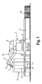
- FIG. 1 1 is a self-propelled combine harvester, which receives a preferably replaceable header 2 in its front region.
- This crop header 2 has a relatively large working width and thus extends on both sides to a considerable extent over the width of the combine harvester 1, ie across the width of the chassis, threshing etc.
- the header 2 is preferably a cutting unit for harvesting grain or rapeseed.
- the combine harvester 1 in its central region, behind a driver's cab, not shown, a grain tank 3, from which a designed as a grain tank outlet pipe 4 conveyor pipe on a seen in the direction of travel, left longitudinal side of the combine 1 starts.
- This grain tank outlet pipe 4 is in the in the FIG. 1 illustrated Swung out position for emptying the grain tank 3.
- the grain tank outlet pipe 4 can also be transferred to a transport position of the combine harvester 1, in which it runs parallel to its longitudinal extent.
- the grain tank outlet pipe 4 in its interior a screw conveyor, not shown, which serves for emptying the grain tank 3.
- straw and chaff are transported via not shown hoppers and strainers to the rear end of the combine harvester 1 and into a chopper 5 arranged there for chopping and evenly distributing the straw and chaff over the area of the field harvested by the combine harvester 1, So take care of the stubble.
- the grain tank outlet pipe 4 has an angled outlet nozzle 6 which deflects the crop conveyed through the grain tank outlet pipe 4 in such a way that it passes as crop stream 7 into a collecting container 8 arranged next to the combine harvester 1.
- This collecting container 8 has, on the one hand, a closed bottom 9 and, on the other hand, a circumferential side wall 10 or individual side walls, the collecting container 8 being provided at least partially with an opening on its upper side.
- the mobile collecting container 8 is arranged on a chassis 11, so that it can be moved during a Abtankvorgangs while continuing the harvesting process parallel to the combine harvester 1 in a fixed relative position thereto.
- 8 data are transmitted from the combine harvester 1 via a radio link 12 between the combine harvester 1 and a not shown in this figure drive unit of the collecting container.
- the header 2 of the not yet harvested Halmgut beau 13 is shown.
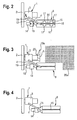
- FIG. 2 is essentially the same arrangement as above FIG. 1 has been explained, but this is a highly schematic and reduced representation of this arrangement in a plan view.
- the collecting container 8 is pulled by an agricultural tractor 14, which thus forms an indirect drive unit of the collecting container 8.
- This farm tractor 14 is already over in connection with the FIG. 1 mentioned radio link 12 with the combine 1 in conjunction.
- at least the combine harvester 1 should have a navigation system via which the respective position of the combine harvester 1 can be detected by GPS.
- the tractor 14 may have a navigation system, these two systems must be coordinated with each other so that the combine harvester 1 and pulled by the tractor 14 collection container 8 are constantly positioned to move to each other. From the FIG. 2 goes further, that the header 2 of the combine harvester 1 extends beyond this on both sides and that the drawn by the tractors 14 collection container 8 behind this header 2, ie within its extension, moves.
- the feed takes place in the front region of the collecting container 8, and the screw conveyor 15 transports the crop as a longitudinal conveyor in the other areas of the collecting container 8.
- the auger 15 can, as in FIG. 2 represented, be arranged within a conveyor trough 16, which has a plurality of adjustable outlet regions 17.
- a sensor 18 for monitoring the filling state of the collecting container 8.
- distance sensors 19 are arranged both on the combine harvester 1 and on the tractors 14, which are independent of the control of the two vehicles 1 and 14 or 8 take over the navigation system an additional safety function, that is, prevent a possible collision of the two vehicles 1 and 8 or 14.
- FIG. 3 The representation after the FIG. 3 basically agrees with the after FIG. 2 why the same reference numbers are used.
- the chopper 5 has a guide 19 for adjusting a straw and chaff distribution behind the combine harvester.
- This guide device 19 is adjustable via an adjusting element 20 such that a spreading width 20a can be reduced on one side behind the combine harvester 1.
- the chopped ingredients are applied only in an area on the stubble, which is outside of the overflowed from the reservoir 8 area.
- a loading hopper 21 is provided, in which the grain tank outlet pipe 4 opens. From this loading hopper 21 goes out in this case, the screw conveyor 15. As continues from the FIG. 4 shows, this loading hopper 21 is located in an area above a drawbar over which the mobile collecting container 8 is coupled to the tractor 14.
- the mobile collecting container 8 is pulled by a Trac vehicle 22, this Trac vehicle 22 having a rear loading area 23.
- a buffer 24 is provided, from which the crop is conveyed via an intermediate conveyor 25 to the arranged in the collecting container 8 screw conveyor 15.
- the screw conveyor 15 takes over together with guide devices, not shown, the distribution of the crop in the sump. 8
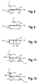
- FIGS. 6 and 7 show an arrangement in which the collecting container 8 also performs a synchronous movement to the combine 1. This is opposite to the combine harvester can take the sump only if not mowed in full stock or the grain tank outlet pipe 4 at any time on the side of the unmown Inventory is located.
- the grain tank outlet pipe 4 should end in the middle of the collecting container 8 and thus promote the at least one screw conveyor 15 in opposite directions of the collecting container 8.
- the screw conveyor 15 may be divided, wherein the two parts are driven with different directions of rotation; but it can also be a wave with opposite spiral course, so that in the same direction of rotation of the two sections a promotion in the direction of the two ends of the collecting container 8 takes place.
- FIG. 7 the crop is fed laterally in the front region of the collecting container 8, for which purpose a lateral loading hopper 26 is provided. About this loading hopper 26, the crop enters the inlet region of the screw conveyor 15th
- FIGS. 8 to 12 Additional information regarding the inventive design of the collecting container 8 and the filling device are the FIGS. 8 to 12 refer to.
- FIG. 8 will be in accordance with the FIG. 2 the crop is fed by means of the grain tank outlet pipe 4 and its outlet nozzle 6 in the front region of the collecting container 8, wherein the screw conveyor 15 distributes the crop over the entire length of the collecting container 8.
- FIG. 9 the supply of the crop takes place in the middle of the collecting container 8, as in FIG. 6 intended.
- the collecting container 8 but also in contrast to the arrangement according to FIG. 6 located together with the tractor 14 within the extension of the header 2.
- FIG. 10 8 further sensors 27 and 28 are provided for monitoring a Be HeilllShes of the collecting container 8 in its central region in the upper region of the collecting container 8 in order to achieve a complete filling.
- FIGS. 11 and 12 If the feed of the crop to the auger 15 to be monitored.
- an ultrasonic sensor 29 is provided which monitors the Erntegutstrom 7 and reports on the corresponding electronic system malfunctions to a non-illustrated, arranged in the cab of the combine 1 monitor.
- the same function can be done according to FIG. 12 take over a camera 30, which transmits messages via an image processing system to the monitor.
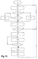
- step S3 it is determined whether, during the unloading process behind the harvesting attachment 2, that is to say according to A1, an unloading takes place during the operation of a chopper 5. If this is the case, a unilaterally reduced shredded material distribution is activated via the path "yes" after step S6.
- step S3 is followed by a method step S4 via a path "no". If after step S4 the Abtankfunktion "off” or moves the sump 8 next to the header 2, so takes place on the path "yes” according to a method step S 5, a normal Humbleburgburgtrieb instead. Subsequently, according to method steps S7, the status of the collecting container 8 and the combine-unloading process are determined. After step S8, it is checked whether or not an unloading operation is given to the collecting container 8 and the combine harvester. If this is not the case, then the system is reset via the path "no", that is, the procedure starts again after the step S1 of the activation of the automatic decoupling system. The procedure is continued via the path "yes", and thus the filling is switched on under method step S9.
- the status of the collecting container 8 and the combine-unloading operation are determined, wherein it is checked under S11 whether the Abtankvorgang for the combine 1 and the collecting container 8 is released. If this is the case, an appropriate message is sent via the path "yes", and the process continues. If this is not the case, this message is sent via the path "no", and subsequently the Sampling process is aborted under S12.
- different status messages namely "unloading operation”, “collection bin full”, “abandon picking position” or “picking up aborted” occur on a monitor in the cab of the combine harvester 1 and / or the tractor 14 or Trac vehicle 22 is transmitted. In this case, the entire procedure is reset to a position after the start of automatic decoupling, ie after S1.
- the individual method steps reference is also made to the explanations in the list of reference numbers.
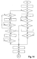
- FIG. 14 is a flowchart for the filling of the collecting container 8, which refers to a filling of the collecting container 8 at an inlet in its central region.
- the automatic filling function is activated, then according to B2 a screw conveyance into the front area, position 1 or rear area, position 2, of the collecting container 8 takes place.
- a query is made as to whether the conveying direction is forward , So position 1, a detected by a sensor level does not yet the position "full” recorded. If this is the case, according to the path "yes” according to step B4, the conveying direction of the screw conveyor is switched on forward or maintain this setting. If this is not the case, then a path "no" is activated, which will be discussed later.
- the collecting container is operated in a fixed relative position to the combine harvester 1 in an advantageous manner.
- the grain tank outlet pipe 4 is also moved to a suitable feed position at the beginning of the Abtankvorgangs.
- the filling device which preferably consists of at least one screw conveyor 15 distributes the crop optimally in the collecting container 8 and via sensors 18, 27 and 28, a message is then issued when the collecting container 8 is completely filled.
- a Abtankvorgang behind the header 2 of the combine harvester 1 can be done and that when switched on shredder 5, the distribution of the shredded material is made such that it is not promoted in the track of the tractor 15 and the associated with this collecting 8.
- a variety of monitoring functions is provided, which ensure that even under unfavorable conditions, the entire Erntegutstrom 7 is supplied to the sump and distributed optimally on this.
Landscapes
- Life Sciences & Earth Sciences (AREA)
- Environmental Sciences (AREA)
- Engineering & Computer Science (AREA)
- Mechanical Engineering (AREA)
- Soil Sciences (AREA)
- Aviation & Aerospace Engineering (AREA)
- Combines (AREA)
- Threshing Machine Elements (AREA)
Priority Applications (1)
| Application Number | Priority Date | Filing Date | Title |
|---|---|---|---|
| PL12157628T PL2526752T3 (pl) | 2011-05-25 | 2012-03-01 | Urządzenie żniwne |
Applications Claiming Priority (1)
| Application Number | Priority Date | Filing Date | Title |
|---|---|---|---|
| DE102011050629A DE102011050629A1 (de) | 2011-05-25 | 2011-05-25 | Erntevorrichtung |
Publications (2)
| Publication Number | Publication Date |
|---|---|
| EP2526752A1 EP2526752A1 (de) | 2012-11-28 |
| EP2526752B1 true EP2526752B1 (de) | 2014-05-14 |
Family
ID=45841196
Family Applications (1)
| Application Number | Title | Priority Date | Filing Date |
|---|---|---|---|
| EP12157628.4A Active EP2526752B1 (de) | 2011-05-25 | 2012-03-01 | Erntevorrichtung |
Country Status (5)
| Country | Link |
|---|---|
| US (2) | US8814640B2 (pl) |
| EP (1) | EP2526752B1 (pl) |
| DE (1) | DE102011050629A1 (pl) |
| PL (1) | PL2526752T3 (pl) |
| RU (1) | RU2569566C2 (pl) |
Families Citing this family (116)
| Publication number | Priority date | Publication date | Assignee | Title |
|---|---|---|---|---|
| DE102011050629A1 (de) * | 2011-05-25 | 2012-11-29 | Claas Selbstfahrende Erntemaschinen Gmbh | Erntevorrichtung |
| US8589013B2 (en) * | 2011-10-25 | 2013-11-19 | Jaybridge Robotics, Inc. | Method and system for dynamically positioning a vehicle relative to another vehicle in motion |
| US9392746B2 (en) | 2012-02-10 | 2016-07-19 | Deere & Company | Artificial intelligence for detecting and filling void areas of agricultural commodity containers |
| US8868304B2 (en) * | 2012-02-10 | 2014-10-21 | Deere & Company | Method and stereo vision system for facilitating the unloading of agricultural material from a vehicle |
| US8844251B2 (en) * | 2012-12-10 | 2014-09-30 | Deere & Company | Cotton accumulator system with paddles and upper inlet vane |
| US9497898B2 (en) * | 2013-01-24 | 2016-11-22 | Tribine Industries, LLC | Agricultural harvester unloading assist system and method |
| US20140255143A1 (en) * | 2013-03-08 | 2014-09-11 | Joel Stave | Controller Configured to Control Power from Source to Drain |
| DE102013012026A1 (de) | 2013-07-19 | 2015-01-22 | Claas Selbstfahrende Erntemaschinen Gmbh | Fahrzeugverbund, Vorrichtung und Verfahren zu dessen Koordination |
| US9188986B2 (en) | 2013-10-01 | 2015-11-17 | Jaybridge Robotics, Inc. | Computer-implemented method and system for dynamically positioning a vehicle relative to another vehicle in motion for on-the-fly offloading operations |
| WO2015057630A1 (en) * | 2013-10-14 | 2015-04-23 | Kinze Manufacturing, Inc. | Autonomous systems, methods, and apparatus for ag based operations |
| BE1021164B1 (nl) * | 2013-10-28 | 2016-01-18 | Cnh Industrial Belgium Nv | Ontlaadsystemen |
| DE102013018820B4 (de) | 2013-11-05 | 2016-12-01 | Hochschule für Technik und Wirtschaft Dresden | Geräteträgersystem |
| DE102014100136A1 (de) * | 2014-01-08 | 2015-07-09 | Claas Selbstfahrende Erntemaschinen Gmbh | Erntevorrichtung |
| US9529364B2 (en) * | 2014-03-24 | 2016-12-27 | Cnh Industrial America Llc | System for coordinating agricultural vehicle control for loading a truck |
| US9469383B1 (en) | 2014-04-16 | 2016-10-18 | Google Inc. | Rainwater harvesting system |
| BR102015013229B8 (pt) | 2014-06-13 | 2021-12-14 | Cnh Ind America Llc | Sistema de controle para um veículo agrícola e método para calibrar o alinhamento de uma saída do transportador de um veículo agrícola com um compartimento de armazenamento |
| BR102015013228B1 (pt) | 2014-06-13 | 2020-11-24 | Cnh Industrial America Llc | SISTEMA E METODO DE CONTROLE PARA UM VEfCULO AGRiCOLA |
| WO2016002623A1 (ja) * | 2014-06-30 | 2016-01-07 | ヤンマー株式会社 | 併走作業システム |
| DE102014113001A1 (de) | 2014-09-10 | 2016-03-10 | Claas Selbstfahrende Erntemaschinen Gmbh | Verfahren zur Steuerung eines Überladeprozesses |
| DE102014113874A1 (de) * | 2014-09-25 | 2016-03-31 | Claas Selbstfahrende Erntemaschinen Gmbh | Verfahren zum Überladen bei Erntemaschinen |
| DE102015101662A1 (de) * | 2015-02-05 | 2016-08-11 | Claas Selbstfahrende Erntemaschinen Gmbh | System zur Ermittlung des Befüllgewichts eines fahrbaren Sammelbehälters |
| DE102015118767A1 (de) * | 2015-11-03 | 2017-05-04 | Claas Selbstfahrende Erntemaschinen Gmbh | Umfelddetektionseinrichtung für landwirtschaftliche Arbeitsmaschine |
| US9675008B1 (en) * | 2016-02-29 | 2017-06-13 | Cnh Industrial America Llc | Unloading arrangement for agricultural harvesting vehicles |
| DE102016003562B4 (de) * | 2016-03-23 | 2022-09-22 | Bomag Gmbh | Fräszug sowie Verfahren |
| JP6697964B2 (ja) * | 2016-06-27 | 2020-05-27 | 株式会社クボタ | コンバイン |
| DE102016116043A1 (de) | 2016-08-29 | 2018-03-01 | Claas Selbstfahrende Erntemaschinen Gmbh | Transportfahrzeug |
| SE542763C2 (en) | 2017-03-14 | 2020-07-07 | Scania Cv Ab | Target arrangement, method, and control unit for following a tar-get vehicle |
| NL2020077B1 (nl) * | 2017-12-13 | 2019-06-21 | Lely Patent Nv | Autonoom landbouwvoertuig |
| CA3116429A1 (en) * | 2018-10-24 | 2020-04-30 | Bitstrata Systems Inc. | Machine operational state and material movement tracking |
| US11079725B2 (en) | 2019-04-10 | 2021-08-03 | Deere & Company | Machine control using real-time model |
| US11957072B2 (en) | 2020-02-06 | 2024-04-16 | Deere & Company | Pre-emergence weed detection and mitigation system |
| US11641800B2 (en) | 2020-02-06 | 2023-05-09 | Deere & Company | Agricultural harvesting machine with pre-emergence weed detection and mitigation system |
| US11672203B2 (en) | 2018-10-26 | 2023-06-13 | Deere & Company | Predictive map generation and control |
| US11178818B2 (en) | 2018-10-26 | 2021-11-23 | Deere & Company | Harvesting machine control system with fill level processing based on yield data |
| US12069978B2 (en) | 2018-10-26 | 2024-08-27 | Deere & Company | Predictive environmental characteristic map generation and control system |
| US11240961B2 (en) | 2018-10-26 | 2022-02-08 | Deere & Company | Controlling a harvesting machine based on a geo-spatial representation indicating where the harvesting machine is likely to reach capacity |
| US11589509B2 (en) | 2018-10-26 | 2023-02-28 | Deere & Company | Predictive machine characteristic map generation and control system |
| US11467605B2 (en) | 2019-04-10 | 2022-10-11 | Deere & Company | Zonal machine control |
| US11653588B2 (en) | 2018-10-26 | 2023-05-23 | Deere & Company | Yield map generation and control system |
| US11240954B2 (en) * | 2019-02-01 | 2022-02-08 | Cnh Industrial Canada, Ltd. | Agricultural agitating and leveling system |
| US11297763B2 (en) | 2019-02-01 | 2022-04-12 | Cnh Industrial Canada, Ltd. | Agitation and leveling system for particulate material |
| US11665995B2 (en) | 2019-02-01 | 2023-06-06 | Cnh Industrial Canada, Ltd. | Agitation control system |
| US11234366B2 (en) | 2019-04-10 | 2022-02-01 | Deere & Company | Image selection for machine control |
| US11778945B2 (en) | 2019-04-10 | 2023-10-10 | Deere & Company | Machine control using real-time model |
| US11160208B2 (en) * | 2019-04-29 | 2021-11-02 | Deere & Company | Method and apparatus for sensing crop material in a harvester |
| US12353210B2 (en) | 2019-07-25 | 2025-07-08 | Ag Leader Technology | Apparatus, systems and methods for automated navigation of agricultural equipment |
| US11310963B2 (en) | 2019-10-31 | 2022-04-26 | Deere & Company | Automated fill strategy for grain cart using open-loop volumetric estimation of fill level |
| RU2726105C1 (ru) * | 2019-11-25 | 2020-07-09 | Сергей Владимирович Бриндюк | Способ осуществления технологических операций выращивания сельскохозяйственных культур |
| US12035648B2 (en) | 2020-02-06 | 2024-07-16 | Deere & Company | Predictive weed map generation and control system |
| US12225846B2 (en) | 2020-02-06 | 2025-02-18 | Deere & Company | Machine control using a predictive map |
| US12329148B2 (en) | 2020-02-06 | 2025-06-17 | Deere & Company | Predictive weed map and material application machine control |
| US11477940B2 (en) | 2020-03-26 | 2022-10-25 | Deere & Company | Mobile work machine control based on zone parameter modification |
| US11635768B2 (en) | 2020-04-28 | 2023-04-25 | Cnh Industrial America Llc | System for coordinating control of multiple work vehicles |
| US12583509B1 (en) | 2020-05-18 | 2026-03-24 | Ag Leader Technology | Assisted steering apparatus and associated systems and methods |
| DE102020124509A1 (de) * | 2020-09-21 | 2022-03-24 | Claas E-Systems Gmbh | Verfahren zur Steuerung der Erntegutüberladung |
| US11592822B2 (en) | 2020-10-09 | 2023-02-28 | Deere & Company | Machine control using a predictive map |
| US20220110238A1 (en) | 2020-10-09 | 2022-04-14 | Deere & Company | Machine control using a predictive map |
| US11983009B2 (en) | 2020-10-09 | 2024-05-14 | Deere & Company | Map generation and control system |
| US11474523B2 (en) | 2020-10-09 | 2022-10-18 | Deere & Company | Machine control using a predictive speed map |
| US11946747B2 (en) | 2020-10-09 | 2024-04-02 | Deere & Company | Crop constituent map generation and control system |
| US12419220B2 (en) | 2020-10-09 | 2025-09-23 | Deere & Company | Predictive map generation and control system |
| US11650587B2 (en) | 2020-10-09 | 2023-05-16 | Deere & Company | Predictive power map generation and control system |
| US11844311B2 (en) | 2020-10-09 | 2023-12-19 | Deere & Company | Machine control using a predictive map |
| US11675354B2 (en) | 2020-10-09 | 2023-06-13 | Deere & Company | Machine control using a predictive map |
| US11635765B2 (en) | 2020-10-09 | 2023-04-25 | Deere & Company | Crop state map generation and control system |
| US11845449B2 (en) | 2020-10-09 | 2023-12-19 | Deere & Company | Map generation and control system |
| US12013245B2 (en) | 2020-10-09 | 2024-06-18 | Deere & Company | Predictive map generation and control system |
| US11825768B2 (en) | 2020-10-09 | 2023-11-28 | Deere & Company | Machine control using a predictive map |
| US11871697B2 (en) | 2020-10-09 | 2024-01-16 | Deere & Company | Crop moisture map generation and control system |
| US12069986B2 (en) | 2020-10-09 | 2024-08-27 | Deere & Company | Map generation and control system |
| US11849672B2 (en) | 2020-10-09 | 2023-12-26 | Deere & Company | Machine control using a predictive map |
| US11889788B2 (en) | 2020-10-09 | 2024-02-06 | Deere & Company | Predictive biomass map generation and control |
| US11895948B2 (en) | 2020-10-09 | 2024-02-13 | Deere & Company | Predictive map generation and control based on soil properties |
| US12422847B2 (en) | 2020-10-09 | 2025-09-23 | Deere & Company | Predictive agricultural model and map generation |
| US11849671B2 (en) | 2020-10-09 | 2023-12-26 | Deere & Company | Crop state map generation and control system |
| US11864483B2 (en) | 2020-10-09 | 2024-01-09 | Deere & Company | Predictive map generation and control system |
| US12386354B2 (en) | 2020-10-09 | 2025-08-12 | Deere & Company | Predictive power map generation and control system |
| US11727680B2 (en) | 2020-10-09 | 2023-08-15 | Deere & Company | Predictive map generation based on seeding characteristics and control |
| US20220110258A1 (en) | 2020-10-09 | 2022-04-14 | Deere & Company | Map generation and control system |
| US12550802B2 (en) | 2020-10-08 | 2026-02-17 | Deere & Company | Predictive machine characteristic map generation and control system |
| US11927459B2 (en) | 2020-10-09 | 2024-03-12 | Deere & Company | Machine control using a predictive map |
| US11711995B2 (en) | 2020-10-09 | 2023-08-01 | Deere & Company | Machine control using a predictive map |
| US11874669B2 (en) | 2020-10-09 | 2024-01-16 | Deere & Company | Map generation and control system |
| US12178158B2 (en) | 2020-10-09 | 2024-12-31 | Deere & Company | Predictive map generation and control system for an agricultural work machine |
| US11889787B2 (en) | 2020-10-09 | 2024-02-06 | Deere & Company | Predictive speed map generation and control system |
| US12250905B2 (en) | 2020-10-09 | 2025-03-18 | Deere & Company | Machine control using a predictive map |
| US12127500B2 (en) | 2021-01-27 | 2024-10-29 | Deere & Company | Machine control using a map with regime zones |
| US11980134B2 (en) | 2021-03-09 | 2024-05-14 | Deere & Company | Operator commanded placement for control of filling mechanisms |
| US12004449B2 (en) | 2021-03-24 | 2024-06-11 | Deere & Company | Control system for controlling filling mechanisms in communication with a mobile device |
| US12403950B2 (en) | 2021-04-19 | 2025-09-02 | Ag Leader Technology | Automatic steering systems and methods |
| US11765993B2 (en) * | 2021-05-17 | 2023-09-26 | Deere & Company | Control system detecting fill level on receiving vehicle(s) |
| US11930738B2 (en) | 2021-06-28 | 2024-03-19 | Deere & Company | Closed loop control of filling mechanisms |
| US11999379B2 (en) * | 2021-08-05 | 2024-06-04 | Cnh Industrial America Llc | Systems and methods for controlling a work vehicle |
| US12229886B2 (en) | 2021-10-01 | 2025-02-18 | Deere & Company | Historical crop state model, predictive crop state map generation and control system |
| US11903344B2 (en) * | 2021-11-16 | 2024-02-20 | Cnh Industrial America Llc | System and method for controlling unloading system position of an agricultural harvester |
| US12310286B2 (en) | 2021-12-14 | 2025-05-27 | Deere & Company | Crop constituent sensing |
| US12302791B2 (en) | 2021-12-20 | 2025-05-20 | Deere & Company | Crop constituents, predictive mapping, and agricultural harvester control |
| US12245549B2 (en) | 2022-01-11 | 2025-03-11 | Deere & Company | Predictive response map generation and control system |
| US12520759B2 (en) | 2022-01-26 | 2026-01-13 | Deere & Company | Systems and methods for predicting material dynamics |
| US12082531B2 (en) | 2022-01-26 | 2024-09-10 | Deere & Company | Systems and methods for predicting material dynamics |
| US12295288B2 (en) | 2022-04-05 | 2025-05-13 | Deere &Company | Predictive machine setting map generation and control system |
| US12358493B2 (en) | 2022-04-08 | 2025-07-15 | Deere & Company | Systems and methods for predictive power requirements and control |
| US12582035B2 (en) | 2022-04-08 | 2026-03-24 | Deere & Company | Systems and methods for predictive power requirements and control |
| US12058951B2 (en) | 2022-04-08 | 2024-08-13 | Deere & Company | Predictive nutrient map and control |
| US12284934B2 (en) | 2022-04-08 | 2025-04-29 | Deere & Company | Systems and methods for predictive tractive characteristics and control |
| US12298767B2 (en) | 2022-04-08 | 2025-05-13 | Deere & Company | Predictive material consumption map and control |
| US12604791B2 (en) | 2022-07-06 | 2026-04-21 | Deere & Company | Machine control based upon estimated operator skill level trend |
| CA3251707A1 (en) | 2022-08-11 | 2024-02-15 | Deere & Company | PREDICTIVE HARVEST LOGISTICS SYSTEMS AND PROCESSES |
| AU2022473991A1 (en) | 2022-08-11 | 2024-11-14 | Deere & Company | Systems and methods for predictive harvesting logistics |
| US12588593B2 (en) | 2022-10-27 | 2026-03-31 | Deere & Company | Fill profile and tracking control during an unloading operation based on a CAD file |
| US12543655B2 (en) | 2022-10-27 | 2026-02-10 | Deere & Company | Controlling transfer of material from a transfer vehicle to a haulage vehicle based on an internal profile of the haulage vehicle |
| WO2024142863A1 (ja) * | 2022-12-28 | 2024-07-04 | 株式会社クボタ | 作業車両、自走式タンクおよび収穫システム |
| DE102023100539A1 (de) * | 2023-01-11 | 2024-07-11 | Deere & Company | Anordnung zur selbsttätigen Kontrolle eines Überladevorgangs von einer Erntemaschine auf ein Transportfahrzeug unter Berücksichtigung von Ernteguteigenschaften |
| US12582033B2 (en) | 2023-04-13 | 2026-03-24 | Deere & Company | Systems and methods for automated grain cart unloading |
| US12472911B2 (en) | 2023-07-11 | 2025-11-18 | Deere & Company | Systems and methods for ground distance control |
| US12588589B2 (en) | 2023-10-02 | 2026-03-31 | Deere & Company | Systems and methods for controlling harvested material fill profiles |
Family Cites Families (33)
| Publication number | Priority date | Publication date | Assignee | Title |
|---|---|---|---|---|
| US4029228A (en) * | 1975-09-26 | 1977-06-14 | Allis-Chalmers Corporation | Self-raising bin loading auger for combines |
| US4008819A (en) * | 1975-09-26 | 1977-02-22 | Allis-Chalmers Corporation | Self-raising bin loading auger for combines |
| DE4403893A1 (de) * | 1994-02-08 | 1995-08-10 | Claas Ohg | Vorrichtung zur automatischen Befüllung von Ladebehältern mit einem Gutstrom |
| DE19531662A1 (de) * | 1995-08-29 | 1997-03-06 | Claas Ohg | Vorrichtung zum automatischen Befüllen von Ladebehältern |
| DE19647522A1 (de) * | 1996-11-16 | 1998-05-20 | Claas Ohg | Vorrichtung zur Überwachung der Überladung von Gütern von einer Arbeitsmaschine auf ein Transportfahrzeug |
| US6012272A (en) * | 1998-03-18 | 2000-01-11 | Dillon; Ben N. | Articulated combine |
| DE19848127A1 (de) * | 1998-10-19 | 2000-04-20 | Claas Selbstfahr Erntemasch | Vorrichtung zur Steuerung einer Überladeeinrichtung |
| DE10021664B4 (de) * | 2000-05-04 | 2004-05-06 | Maschinenfabrik Bernard Krone Gmbh | Erntemaschine, insbesondere selbstfahrender Feldhäcksler |
| DE10064862A1 (de) | 2000-12-23 | 2002-07-11 | Claas Selbstfahr Erntemasch | Vorrichtung und Verfahren zur Koordination und Einstellung von landwirtschaftlichen Fahrzeugen |
| DE10064860A1 (de) * | 2000-12-23 | 2002-06-27 | Claas Selbstfahr Erntemasch | Einrichtung zur Optimierung der Überladung von Erntegut an landwirtschaftlichen Fahrzeugen |
| US6682416B2 (en) * | 2000-12-23 | 2004-01-27 | Claas Selbstfahrende Erntemaschinen Gmbh | Automatic adjustment of a transfer device on an agricultural harvesting machine |
| DE10134137B4 (de) * | 2001-07-13 | 2006-02-23 | Maschinenfabrik Bernard Krone Gmbh | Selbstfahrende landwirtschaftliche Erntemaschine |
| US6943824B2 (en) * | 2002-03-13 | 2005-09-13 | Deere & Company | Image processing spout control system |
| DE10224939B4 (de) * | 2002-05-31 | 2009-01-08 | Deere & Company, Moline | Triebachs-Anhänger |
| DE10240219A1 (de) * | 2002-08-28 | 2004-03-11 | Claas Selbstfahrende Erntemaschinen Gmbh | Vorrichtung zur Steuerung einer Überladeeinrichtung |
| DE10242164A1 (de) * | 2002-09-10 | 2004-04-01 | Claas Selbstfahrende Erntemaschinen Gmbh | Verfahren zur Steuerung einer Überladeeinrichtung |
| DE102004039460B3 (de) * | 2004-08-14 | 2006-04-20 | Deere & Company, Moline | System zur Bestimmung der relativen Position eines zweiten landwirtschaftlichen Fahrzeugs in Bezug auf ein erstes landwirtschaftliches Fahrzeug |
| DE102004052298A1 (de) * | 2004-10-06 | 2006-06-08 | Claas Selbstfahrende Erntemaschinen Gmbh | Überladeassistenzsystem |
| US20060271262A1 (en) * | 2005-05-24 | 2006-11-30 | Mclain Harry P Iii | Wireless agricultural network |
| DE102005038553A1 (de) * | 2005-08-12 | 2007-02-22 | Claas Selbstfahrende Erntemaschinen Gmbh | Verfahren zum Überladen von Erntegut |
| DE102005059003A1 (de) * | 2005-12-08 | 2008-03-27 | Claas Selbstfahrende Erntemaschinen Gmbh | Routenplanungssystem für landwirtschaftliche Arbeitsmaschinen |
| US8060283B2 (en) * | 2007-10-15 | 2011-11-15 | Deere & Company | Method and system for controlling the loading of a container associated with a vehicle |
| US8160765B2 (en) * | 2008-03-03 | 2012-04-17 | Cnh America Llc | Method and system for coordinated vehicle control with wireless communication |
| DE102008002006A1 (de) * | 2008-05-27 | 2009-12-03 | Deere & Company, Moline | Steueranordnung zur Kontrolle des Überladens landwirtschaftlichen Ernteguts von einer Erntemaschine auf ein Transportfahrzeug |
| US8145393B2 (en) * | 2008-09-17 | 2012-03-27 | Cnh America Llc | System and method employing short range communications for interactively coordinating unloading operations between a harvester and a grain transport |
| US8180534B2 (en) * | 2008-09-18 | 2012-05-15 | Deere & Company | Multiple harvester unloading system |
| US7836673B2 (en) * | 2008-12-17 | 2010-11-23 | Cnh America Llc | Cotton harvesting machine with on-board module builder and integrated module transporter having on-the-go unloading capability and method of operation of the same |
| US8126620B2 (en) | 2009-04-28 | 2012-02-28 | Cnh America Llc | Grain transfer control system and method |
| US7877181B2 (en) * | 2009-05-11 | 2011-01-25 | Deere & Company | Scalable grain tank fill level display |
| US8380401B2 (en) * | 2010-06-09 | 2013-02-19 | Cnh America Llc | Automatic grain transfer control system based on real time modeling of a fill level profile for regions of the receiving container |
| DE102010038661B4 (de) * | 2010-07-29 | 2020-07-02 | Deere & Company | Erntemaschine mit einem an einem Fluggerät befestigten Sensor |
| US9002591B2 (en) * | 2011-02-18 | 2015-04-07 | Cnh Industrial America Llc | Harvester spout control system and method |
| DE102011050629A1 (de) * | 2011-05-25 | 2012-11-29 | Claas Selbstfahrende Erntemaschinen Gmbh | Erntevorrichtung |
-
2011
- 2011-05-25 DE DE102011050629A patent/DE102011050629A1/de not_active Withdrawn
-
2012
- 2012-03-01 EP EP12157628.4A patent/EP2526752B1/de active Active
- 2012-03-01 PL PL12157628T patent/PL2526752T3/pl unknown
- 2012-05-07 US US13/465,204 patent/US8814640B2/en active Active
- 2012-05-24 RU RU2012121266/13A patent/RU2569566C2/ru active
-
2013
- 2013-05-06 US US13/887,505 patent/US8662972B2/en active Active
Also Published As
| Publication number | Publication date |
|---|---|
| US8814640B2 (en) | 2014-08-26 |
| US20120302299A1 (en) | 2012-11-29 |
| RU2012121266A (ru) | 2013-11-27 |
| US20130243562A1 (en) | 2013-09-19 |
| DE102011050629A1 (de) | 2012-11-29 |
| EP2526752A1 (de) | 2012-11-28 |
| RU2569566C2 (ru) | 2015-11-27 |
| PL2526752T3 (pl) | 2014-10-31 |
| US8662972B2 (en) | 2014-03-04 |
Similar Documents
| Publication | Publication Date | Title |
|---|---|---|
| EP2526752B1 (de) | Erntevorrichtung | |
| EP3662741B1 (de) | Landwirtschaftliche arbeitsmaschine sowie verfahren zum betreiben einer landwirtschaftlichen arbeitsmaschine | |
| DE102008006882B4 (de) | Erntemaschinenkombination zur Pflanzenresteverwertung | |
| DE10134137B4 (de) | Selbstfahrende landwirtschaftliche Erntemaschine | |
| EP2574229B1 (de) | Selbstfahrende landwirtschaftliche Erntemaschine mit einem um eine vertikale Achse schwenkbaren Erntevorsatz | |
| DE102016202628B4 (de) | Sensoranordnung zur Funktionsüberwachung eines Erntevorsatzes | |
| DD149451A5 (de) | Selbstfahrender maehdrescher | |
| DE2418995C2 (pl) | ||
| WO1994004020A2 (de) | Selbstfahrende ballenpresse für auf dem feld angebaute pflanzen | |
| EP3637981B1 (de) | Überladevorrichtung zum aufsammeln und übergeben von erntegut an einen transportwagen | |
| EP4252519B1 (de) | Landwirtschaftliche erntemaschine sowie verfahren zur steuerung einer landwirtschaftlichen erntemaschine | |
| EP3053428B1 (de) | System zur ermittlung des befüllgewichts eines fahrbaren sammelbehälters | |
| AT513427B1 (de) | Erntewagen zum Aufnehmen und Transport von Pflanzen oder Pflanzenteilen | |
| DE19647433A1 (de) | Verfahren und Vorrichtung zum Hanfdrusch mit Schleppergeräten | |
| EP1932418B1 (de) | Erntevorsatzvorrichtung zum Aufnehmen von am Boden liegendem Erntegut | |
| DE102011083941A1 (de) | Rundballenpresse zur Erzeugung von Ballen aus Erntegutresten | |
| DE102022113247A1 (de) | Pick-up-Vorsatzgerät für eine Erntemaschine | |
| DE102008040217B4 (de) | Zwischen einer Betriebsstellung und einer kompakten Transportstellung verstellbarer Erntevorsatz | |
| DE102007060962A1 (de) | Erntevorsatzvorrichtung zum Aufnehmen von am Boden liegendem Erntegut | |
| EP4697932A1 (de) | Pick-up-vorsatzgerät für eine erntemaschine | |
| EP4464147A1 (de) | Erntevorsatz für einen mähdrescher zur ernte von erntegut mit an halmen wachsenden körnern | |
| WO2024235394A1 (de) | Pick-up-vorsatzgerät für eine erntemaschine | |
| EP4697929A1 (de) | Pick-up-vorsatzgerät für eine erntemaschine | |
| DE202006019069U1 (de) | Vorrichtung zur Aufnahme von am Boden liegendem Erntegut | |
| DE102006059841A1 (de) | Vorrichtung zum Aufnehmen von am Boden liegendem Erntegut |
Legal Events
| Date | Code | Title | Description |
|---|---|---|---|
| PUAI | Public reference made under article 153(3) epc to a published international application that has entered the european phase |
Free format text: ORIGINAL CODE: 0009012 |
|
| AK | Designated contracting states |
Kind code of ref document: A1 Designated state(s): AL AT BE BG CH CY CZ DE DK EE ES FI FR GB GR HR HU IE IS IT LI LT LU LV MC MK MT NL NO PL PT RO RS SE SI SK SM TR |
|
| AX | Request for extension of the european patent |
Extension state: BA ME |
|
| 17P | Request for examination filed |
Effective date: 20130528 |
|
| RBV | Designated contracting states (corrected) |
Designated state(s): AL AT BE BG CH CY CZ DE DK EE ES FI FR GB GR HR HU IE IS IT LI LT LU LV MC MK MT NL NO PL PT RO RS SE SI SK SM TR |
|
| REG | Reference to a national code |
Ref country code: DE Ref legal event code: R079 Ref document number: 502012000708 Country of ref document: DE Free format text: PREVIOUS MAIN CLASS: A01B0069000000 Ipc: A01B0069040000 |
|
| GRAP | Despatch of communication of intention to grant a patent |
Free format text: ORIGINAL CODE: EPIDOSNIGR1 |
|
| RIC1 | Information provided on ipc code assigned before grant |
Ipc: B65G 67/22 20060101ALI20140103BHEP Ipc: A01D 43/07 20060101ALI20140103BHEP Ipc: A01B 69/04 20060101AFI20140103BHEP |
|
| INTG | Intention to grant announced |
Effective date: 20140206 |
|
| GRAS | Grant fee paid |
Free format text: ORIGINAL CODE: EPIDOSNIGR3 |
|
| GRAA | (expected) grant |
Free format text: ORIGINAL CODE: 0009210 |
|
| AK | Designated contracting states |
Kind code of ref document: B1 Designated state(s): AL AT BE BG CH CY CZ DE DK EE ES FI FR GB GR HR HU IE IS IT LI LT LU LV MC MK MT NL NO PL PT RO RS SE SI SK SM TR |
|
| REG | Reference to a national code |
Ref country code: GB Ref legal event code: FG4D Free format text: NOT ENGLISH |
|
| REG | Reference to a national code |
Ref country code: AT Ref legal event code: REF Ref document number: 667516 Country of ref document: AT Kind code of ref document: T Effective date: 20140615 |
|
| REG | Reference to a national code |
Ref country code: IE Ref legal event code: FG4D Free format text: LANGUAGE OF EP DOCUMENT: GERMAN |
|
| REG | Reference to a national code |
Ref country code: DE Ref legal event code: R096 Ref document number: 502012000708 Country of ref document: DE Effective date: 20140626 |
|
| REG | Reference to a national code |
Ref country code: NL Ref legal event code: VDEP Effective date: 20140514 |
|
| REG | Reference to a national code |
Ref country code: LT Ref legal event code: MG4D |
|
| PG25 | Lapsed in a contracting state [announced via postgrant information from national office to epo] |
Ref country code: NO Free format text: LAPSE BECAUSE OF FAILURE TO SUBMIT A TRANSLATION OF THE DESCRIPTION OR TO PAY THE FEE WITHIN THE PRESCRIBED TIME-LIMIT Effective date: 20140814 Ref country code: GR Free format text: LAPSE BECAUSE OF FAILURE TO SUBMIT A TRANSLATION OF THE DESCRIPTION OR TO PAY THE FEE WITHIN THE PRESCRIBED TIME-LIMIT Effective date: 20140815 Ref country code: CY Free format text: LAPSE BECAUSE OF FAILURE TO SUBMIT A TRANSLATION OF THE DESCRIPTION OR TO PAY THE FEE WITHIN THE PRESCRIBED TIME-LIMIT Effective date: 20140514 Ref country code: FI Free format text: LAPSE BECAUSE OF FAILURE TO SUBMIT A TRANSLATION OF THE DESCRIPTION OR TO PAY THE FEE WITHIN THE PRESCRIBED TIME-LIMIT Effective date: 20140514 Ref country code: IS Free format text: LAPSE BECAUSE OF FAILURE TO SUBMIT A TRANSLATION OF THE DESCRIPTION OR TO PAY THE FEE WITHIN THE PRESCRIBED TIME-LIMIT Effective date: 20140914 Ref country code: LT Free format text: LAPSE BECAUSE OF FAILURE TO SUBMIT A TRANSLATION OF THE DESCRIPTION OR TO PAY THE FEE WITHIN THE PRESCRIBED TIME-LIMIT Effective date: 20140514 |
|
| REG | Reference to a national code |
Ref country code: PL Ref legal event code: T3 |
|
| PG25 | Lapsed in a contracting state [announced via postgrant information from national office to epo] |
Ref country code: SE Free format text: LAPSE BECAUSE OF FAILURE TO SUBMIT A TRANSLATION OF THE DESCRIPTION OR TO PAY THE FEE WITHIN THE PRESCRIBED TIME-LIMIT Effective date: 20140514 Ref country code: LV Free format text: LAPSE BECAUSE OF FAILURE TO SUBMIT A TRANSLATION OF THE DESCRIPTION OR TO PAY THE FEE WITHIN THE PRESCRIBED TIME-LIMIT Effective date: 20140514 Ref country code: ES Free format text: LAPSE BECAUSE OF FAILURE TO SUBMIT A TRANSLATION OF THE DESCRIPTION OR TO PAY THE FEE WITHIN THE PRESCRIBED TIME-LIMIT Effective date: 20140514 Ref country code: HR Free format text: LAPSE BECAUSE OF FAILURE TO SUBMIT A TRANSLATION OF THE DESCRIPTION OR TO PAY THE FEE WITHIN THE PRESCRIBED TIME-LIMIT Effective date: 20140514 Ref country code: RS Free format text: LAPSE BECAUSE OF FAILURE TO SUBMIT A TRANSLATION OF THE DESCRIPTION OR TO PAY THE FEE WITHIN THE PRESCRIBED TIME-LIMIT Effective date: 20140514 |
|
| PG25 | Lapsed in a contracting state [announced via postgrant information from national office to epo] |
Ref country code: PT Free format text: LAPSE BECAUSE OF FAILURE TO SUBMIT A TRANSLATION OF THE DESCRIPTION OR TO PAY THE FEE WITHIN THE PRESCRIBED TIME-LIMIT Effective date: 20140915 |
|
| PG25 | Lapsed in a contracting state [announced via postgrant information from national office to epo] |
Ref country code: CZ Free format text: LAPSE BECAUSE OF FAILURE TO SUBMIT A TRANSLATION OF THE DESCRIPTION OR TO PAY THE FEE WITHIN THE PRESCRIBED TIME-LIMIT Effective date: 20140514 Ref country code: SK Free format text: LAPSE BECAUSE OF FAILURE TO SUBMIT A TRANSLATION OF THE DESCRIPTION OR TO PAY THE FEE WITHIN THE PRESCRIBED TIME-LIMIT Effective date: 20140514 Ref country code: EE Free format text: LAPSE BECAUSE OF FAILURE TO SUBMIT A TRANSLATION OF THE DESCRIPTION OR TO PAY THE FEE WITHIN THE PRESCRIBED TIME-LIMIT Effective date: 20140514 Ref country code: DK Free format text: LAPSE BECAUSE OF FAILURE TO SUBMIT A TRANSLATION OF THE DESCRIPTION OR TO PAY THE FEE WITHIN THE PRESCRIBED TIME-LIMIT Effective date: 20140514 Ref country code: RO Free format text: LAPSE BECAUSE OF FAILURE TO SUBMIT A TRANSLATION OF THE DESCRIPTION OR TO PAY THE FEE WITHIN THE PRESCRIBED TIME-LIMIT Effective date: 20140514 |
|
| REG | Reference to a national code |
Ref country code: DE Ref legal event code: R097 Ref document number: 502012000708 Country of ref document: DE |
|
| PG25 | Lapsed in a contracting state [announced via postgrant information from national office to epo] |
Ref country code: NL Free format text: LAPSE BECAUSE OF FAILURE TO SUBMIT A TRANSLATION OF THE DESCRIPTION OR TO PAY THE FEE WITHIN THE PRESCRIBED TIME-LIMIT Effective date: 20140514 |
|
| PLBE | No opposition filed within time limit |
Free format text: ORIGINAL CODE: 0009261 |
|
| STAA | Information on the status of an ep patent application or granted ep patent |
Free format text: STATUS: NO OPPOSITION FILED WITHIN TIME LIMIT |
|
| 26N | No opposition filed |
Effective date: 20150217 |
|
| PG25 | Lapsed in a contracting state [announced via postgrant information from national office to epo] |
Ref country code: IT Free format text: LAPSE BECAUSE OF FAILURE TO SUBMIT A TRANSLATION OF THE DESCRIPTION OR TO PAY THE FEE WITHIN THE PRESCRIBED TIME-LIMIT Effective date: 20140514 |
|
| REG | Reference to a national code |
Ref country code: DE Ref legal event code: R097 Ref document number: 502012000708 Country of ref document: DE Effective date: 20150217 |
|
| PG25 | Lapsed in a contracting state [announced via postgrant information from national office to epo] |
Ref country code: SI Free format text: LAPSE BECAUSE OF FAILURE TO SUBMIT A TRANSLATION OF THE DESCRIPTION OR TO PAY THE FEE WITHIN THE PRESCRIBED TIME-LIMIT Effective date: 20140514 |
|
| PG25 | Lapsed in a contracting state [announced via postgrant information from national office to epo] |
Ref country code: MC Free format text: LAPSE BECAUSE OF FAILURE TO SUBMIT A TRANSLATION OF THE DESCRIPTION OR TO PAY THE FEE WITHIN THE PRESCRIBED TIME-LIMIT Effective date: 20140514 Ref country code: LU Free format text: LAPSE BECAUSE OF FAILURE TO SUBMIT A TRANSLATION OF THE DESCRIPTION OR TO PAY THE FEE WITHIN THE PRESCRIBED TIME-LIMIT Effective date: 20150301 |
|
| REG | Reference to a national code |
Ref country code: CH Ref legal event code: PL |
|
| REG | Reference to a national code |
Ref country code: IE Ref legal event code: MM4A |
|
| PG25 | Lapsed in a contracting state [announced via postgrant information from national office to epo] |
Ref country code: LI Free format text: LAPSE BECAUSE OF NON-PAYMENT OF DUE FEES Effective date: 20150331 Ref country code: CH Free format text: LAPSE BECAUSE OF NON-PAYMENT OF DUE FEES Effective date: 20150331 Ref country code: IE Free format text: LAPSE BECAUSE OF NON-PAYMENT OF DUE FEES Effective date: 20150301 |
|
| REG | Reference to a national code |
Ref country code: FR Ref legal event code: PLFP Year of fee payment: 5 |
|
| GBPC | Gb: european patent ceased through non-payment of renewal fee |
Effective date: 20160301 |
|
| PG25 | Lapsed in a contracting state [announced via postgrant information from national office to epo] |
Ref country code: MT Free format text: LAPSE BECAUSE OF FAILURE TO SUBMIT A TRANSLATION OF THE DESCRIPTION OR TO PAY THE FEE WITHIN THE PRESCRIBED TIME-LIMIT Effective date: 20140514 |
|
| PG25 | Lapsed in a contracting state [announced via postgrant information from national office to epo] |
Ref country code: GB Free format text: LAPSE BECAUSE OF NON-PAYMENT OF DUE FEES Effective date: 20160301 |
|
| REG | Reference to a national code |
Ref country code: FR Ref legal event code: PLFP Year of fee payment: 6 |
|
| PG25 | Lapsed in a contracting state [announced via postgrant information from national office to epo] |
Ref country code: SM Free format text: LAPSE BECAUSE OF FAILURE TO SUBMIT A TRANSLATION OF THE DESCRIPTION OR TO PAY THE FEE WITHIN THE PRESCRIBED TIME-LIMIT Effective date: 20140514 Ref country code: HU Free format text: LAPSE BECAUSE OF FAILURE TO SUBMIT A TRANSLATION OF THE DESCRIPTION OR TO PAY THE FEE WITHIN THE PRESCRIBED TIME-LIMIT; INVALID AB INITIO Effective date: 20120301 Ref country code: BG Free format text: LAPSE BECAUSE OF FAILURE TO SUBMIT A TRANSLATION OF THE DESCRIPTION OR TO PAY THE FEE WITHIN THE PRESCRIBED TIME-LIMIT Effective date: 20140514 |
|
| PG25 | Lapsed in a contracting state [announced via postgrant information from national office to epo] |
Ref country code: TR Free format text: LAPSE BECAUSE OF FAILURE TO SUBMIT A TRANSLATION OF THE DESCRIPTION OR TO PAY THE FEE WITHIN THE PRESCRIBED TIME-LIMIT Effective date: 20140514 |
|
| REG | Reference to a national code |
Ref country code: FR Ref legal event code: PLFP Year of fee payment: 7 |
|
| REG | Reference to a national code |
Ref country code: AT Ref legal event code: MM01 Ref document number: 667516 Country of ref document: AT Kind code of ref document: T Effective date: 20170301 |
|
| PG25 | Lapsed in a contracting state [announced via postgrant information from national office to epo] |
Ref country code: MK Free format text: LAPSE BECAUSE OF FAILURE TO SUBMIT A TRANSLATION OF THE DESCRIPTION OR TO PAY THE FEE WITHIN THE PRESCRIBED TIME-LIMIT Effective date: 20140514 |
|
| PG25 | Lapsed in a contracting state [announced via postgrant information from national office to epo] |
Ref country code: AT Free format text: LAPSE BECAUSE OF NON-PAYMENT OF DUE FEES Effective date: 20170301 |
|
| PG25 | Lapsed in a contracting state [announced via postgrant information from national office to epo] |
Ref country code: AL Free format text: LAPSE BECAUSE OF FAILURE TO SUBMIT A TRANSLATION OF THE DESCRIPTION OR TO PAY THE FEE WITHIN THE PRESCRIBED TIME-LIMIT Effective date: 20140514 |
|
| P01 | Opt-out of the competence of the unified patent court (upc) registered |
Effective date: 20230515 |
|
| REG | Reference to a national code |
Ref country code: DE Ref legal event code: R084 Ref document number: 502012000708 Country of ref document: DE |
|
| PGFP | Annual fee paid to national office [announced via postgrant information from national office to epo] |
Ref country code: PL Payment date: 20250224 Year of fee payment: 14 |
|
| PGFP | Annual fee paid to national office [announced via postgrant information from national office to epo] |
Ref country code: DE Payment date: 20260319 Year of fee payment: 15 |
|
| PGFP | Annual fee paid to national office [announced via postgrant information from national office to epo] |
Ref country code: BE Payment date: 20260319 Year of fee payment: 15 |
|
| PGFP | Annual fee paid to national office [announced via postgrant information from national office to epo] |
Ref country code: FR Payment date: 20260320 Year of fee payment: 15 |