EP2526525B1 - System and method for correcting data for deformations during image-guided procedures - Google Patents
System and method for correcting data for deformations during image-guided procedures Download PDFInfo
- Publication number
- EP2526525B1 EP2526525B1 EP11706049.1A EP11706049A EP2526525B1 EP 2526525 B1 EP2526525 B1 EP 2526525B1 EP 11706049 A EP11706049 A EP 11706049A EP 2526525 B1 EP2526525 B1 EP 2526525B1
- Authority
- EP
- European Patent Office
- Prior art keywords
- computer model
- space
- image
- values
- rigid
- Prior art date
- Legal status (The legal status is an assumption and is not a legal conclusion. Google has not performed a legal analysis and makes no representation as to the accuracy of the status listed.)
- Not-in-force
Links
Images


Classifications
-
- G—PHYSICS
- G06—COMPUTING OR CALCULATING; COUNTING
- G06T—IMAGE DATA PROCESSING OR GENERATION, IN GENERAL
- G06T7/00—Image analysis
- G06T7/30—Determination of transform parameters for the alignment of images, i.e. image registration
- G06T7/33—Determination of transform parameters for the alignment of images, i.e. image registration using feature-based methods
-
- G—PHYSICS
- G06—COMPUTING OR CALCULATING; COUNTING
- G06T—IMAGE DATA PROCESSING OR GENERATION, IN GENERAL
- G06T17/00—Three-dimensional [3D] modelling for computer graphics
-
- A—HUMAN NECESSITIES
- A61—MEDICAL OR VETERINARY SCIENCE; HYGIENE
- A61B—DIAGNOSIS; SURGERY; IDENTIFICATION
- A61B5/00—Measuring for diagnostic purposes; Identification of persons
-
- G—PHYSICS
- G06—COMPUTING OR CALCULATING; COUNTING
- G06G—ANALOGUE COMPUTERS
- G06G7/00—Devices in which the computing operation is performed by varying electric or magnetic quantities
- G06G7/48—Analogue computers for specific processes, systems or devices, e.g. simulators
- G06G7/60—Analogue computers for specific processes, systems or devices, e.g. simulators for living beings, e.g. their nervous systems ; for problems in the medical field
Definitions
- the present invention relates to systems and methods for image-guided procedures, and more specifically to systems and methods for correcting tissue data for deformations during image guided procedures.
- IGS image-guided surgery
- ICP iterative closest point
- iUS intraoperative ultrasound
- the typical protocol for surface-based image-to-physical space registration in abdominal IGS begins with the selection of anatomical fiducial points in the preoperative image sets prior to surgery.
- the homologous physical-space location of these anatomical fiducials is then digitized during the surgical procedure such that a point-based initial alignment registration can be performed.
- the point-based registration serves to provide a reasonable initial pose for the ICP algorithm, which is used to register the tissue surfaces derived from preoperative images and the intraoperative data.
- the surface alignment provided by the ICP algorithm is highly dependent on the initial pose of the tissue surfaces. Therefore, gross errors in the initial alignment provided by the point-based registration can result in erroneous surface alignments.
- initial pose is important
- another aspect of misalignment that can confound the ICP algorithm is the presence of intraoperative deformation. That is when organ and other soft tissues are surgically presented intraoperatively for surface acquisition (such as by laser range scanning), the soft tissues have generally undergone deformation due to routine surgical manipulation. Errors associate with pose or deformation introduced into any form of rigid registration will generall compromise the guidance information relayed to the surgeon.
- Some examples of soft tissu deformation due to surgical manipulation are (1) gravity-induced deformations of the liver due to reorientation of the organ with respect to the direction of gravity in the open-abdomen, (2) the effects of tissue mobilization and organ packing, and (3) changes in organ perfusion.
- Embodiments of the invention concern systems and methods for correcting tissue data for deformations during image guided procedures.
- a method is provided according to claim 1.
- a computer-readable storage medium is provided according to claim 15.
- the displaying can further entail receiving image data associated with the computer model and locations in the patient space associated with the object and neighboring the object and transforming the computer model into the patient space based on the rigid alignment and the deformation.
- the displaying can also include computing reverse deformation displacement vector field values for each node of the computer model based on the deformation and calculating an envelope of additional reverse deformation vector field values for a portion of the patient space surrounding the deformed computed model.
- the displaying can include transforming the locations into a computer model space of the computer model based on the non-rigid alignment and the reverse deformation displacement vector field values and calculating coordinates in an image space of the image data for the transformed locations.
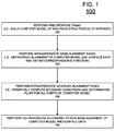
- FIG. 1 is a flowchart showing steps in an exemplary method for performing an IGS procedure in accordance with an embodiment of the invention.
- the method 100 includes a preoperative phase at block 102, an intraoperative rigid alignment phase at block 104, and an intraoperative non-rigid alignment phase at block 106. Following or concurrently with these phases, the IGS procedure can be performed at block 108.
- the method 100 begins at block 102.
- preoperative tasks are performed.
- the preoperative tasks include building a computer (i.e., mathematical) model of at least the soft tissues, organs, or other non-rigid structures of interest in the patient.
- a computer i.e., mathematical
- the various embodiments of the invention will be described with respect to IGS procedures for non-rigid structures, the invention is not limited in this regard. Rather, the various embodiments of the invention are equally applicable in IGS procedures involving one or more rigid structures in a patient (e.g., bones) or a combination of rigid and non-rigid structures.
- the computer model can be built using several sets of preoperative data. For example, preoperative images of the non-rigid structures are acquired and processed to generate a computer model that describes at least the geometry of the non-rigid structures of interest. These can be acquired using two or three dimensional imaging techniques. For example, some imaging techniques include computerized tomography (CT), magnetic resonance (MR), and ultrasound imaging techniques, to name a few. However, the various embodiments of the invention are not limited in this regard and any other imaging techniques can be used. Further, the computer model can also be configured to include any other possible data, such as physical data (e.g., elastic properties, thermoplastic properties, etc. and other aspects relevant to the mechanics of the non-rigid structure) that could be necessary to calculate deformation within the operative environment.
- CT computerized tomography
- MR magnetic resonance
- ultrasound imaging techniques to name a few.
- the various embodiments of the invention are not limited in this regard and any other imaging techniques can be used.
- the computer model can also be configured to include any other possible data,
- tasks for building the computer model can be performed. For example, a distribution of deformation shapes to be used in the fitting process can be generated. Also, preoperative image analysis can be performed in order to enhance feedback or computer mesh generation. Further, pre-operative generation of mathematical functions to assist fitting can be performed. Also, a designation/segmentation of shapes or partial surfaces of the non-rigid structures of interest can be performed. However, the invention is not limited in this regard and other tasks can be performed to enhance the imaging or fitting processes of method 100.
- a "surface" can refer to either external or internal features associated with a non-rigid structure of interest. That is, in addition to external surfaces, the surfaces referred to herein can include internal surfaces or features defined by a boundary between different structures or different types of tissues. For example, a boundary or division between cancerous and healthy tissues can define a surface. In another example, the division between liver vasculature and a parenchyma of a liver can also define a surface. In another example, it could represent the surface or feature point of a synthetic structure inserted within the organ that can be located via some localization methods.
- this preoperative phase can either be performed on one or more computing systems. Further, the preoperative phase can be performed on the same or different computing systems as the intraoperative tasks described bellow are performed.
- An exemplary computing system could include software packages configured to solve large sparse matrices that can be used for mathematical model solutions. Such a computing system could also include software libraries that provide computer model mesh/grid generation. Further, such a computing system can include both standard and customized mathematical and simulation libraries.
- intraoperative rigid alignment tasks are performed. That is, intraoperative surface data for one or more portions of the non-rigid structures is obtained intraoperatively and the counterpart surface data within image-space is obtained and aligned with a mathematical transformation. Thereafter the surface data of the non-rigid structure and the computer model are initially aligned.
- a best-aligned method can be used. As used herein, a best-aligned method is an alignment of the image data and the non-rigid structures so that features on the surface of the non-rigid structures are positioned as close as possible to their image-space counterparts after the conclusion of the alignment process.
- the various embodiments of the invention are not limited in this regard and other alignment schemes can be used as well as internal substructures or feature points.
- a rigid alignment can be performed in a variety of ways. For example, an iterative method can be use to alter the position of one of the surface data and the computer model until an error between the surface data and the computer model is minimized.
- Intraoperative surface data can be obtained in a variety of ways. For example, some methods include ultrasound, MR imaging, CT imaging, laser and/or other light-based strategies, swabbing with a tracked stylus, to name a few. However, the various embodiments of the invention are not limited in this regard and other methods can be used to obtain surface data. In many cases, the surface data obtained will only represent a portion of the non-rigid structure, i.e. a partial surface. For example, during a liver procedure, only the anterior portion of the liver may be exposed. Therefore, the surface data could be acquired using laser range scan technology which would limit geometric data to representing the anterior portion of the liver. In another example, the liver and a tumor may be partially exposed. However, the surface of interest may be a boundary between a tumor and the liver, an interior surface. In such cases, ultrasound imaging could be used to locate such interior surfaces of interest.
- the surface data can also include noise or other errors that could affect alignment. Accordingly, in some embodiments of the invention, once the surface data is acquired, the surface data can be filtered or otherwise processed to reduce or eliminate of noise and/or other artifacts. Such methods are well known to those of ordinary skill in the art and will not be described here. In the various embodiments of the invention, such processing can be performed before or after the rigid alignment. In addition, in some cases where multiple surface data acquisitions from different methods are available and digitized in a common coordinate space, a composite surface can be used for alignment purposes.
- an initial correspondence function is generated that associates each point from the surface data with a counterpart point on the non-rigid structure within image-space. That is, for each point in the surface data, a means is provided for identifying the corresponding point in the computer model. For example, a closest point operator can be used to select the point on the computer model that is closest to each point on the surface data.
- this correspondence function may be expressed as a table, a mathematical function, or any other method of describing a relationship between the spaces defined two sets of points.
- the deformation observed in the surface data may result in the correspondence function associating points from non-corresponding surfaces of the computer model with points on the surface associated with the surface data.
- the closest point operator can be refined or constrained to limit its search to corresponding surfaces. That is, the computer model and the surface data can be associated with designators that differentiate between the various surfaces of the non-rigid structure of interest. Accordingly, the search for corresponding points can be limited by such designators. For example, anterior surface nodes of surface data could be limited to the anterior surface nodes of the computer model, despite the fact that posterior surface nodes of the computer model are closer.
- corresponding points can be selected using a ray projection technique in which a ray is projected along a line perpendicular to a point on one surface and the corresponding point is selected to be the point that is intersected on the second surface.
- method 100 can proceed to block 106.
- a set of boundary or point (internal and/or external) conditions based on the rigid alignment at block 106 and the correspondence function of 104, and a displacement field of vectors in three dimensions is iteratively computed to perform a non-rigid alignment of the computer model to the surface data. That is a displacement field of vectors for deforming the computer model to fit the surface data is computed. The operations occurring in this block will be described below in greater detail with respect to FIG. 2 .
- the IGS procedure can be performed at block 108.
- FIG. 2 is a flow chart of an exemplary method 106 for performing a non-rigid alignment in accordance with and embodiment of the invention.
- Method 106 begins at block 202 and continues on to block 204.
- the correspondence function for the computer model and the surface data is received.
- the correspondence function also identifies a patch region of the computer model.
- a patch region is defined by the portions of the computer model corresponding to the surface data.
- spatial difference values are computed for each node within the patch region.
- node refers to the points of a computer model mesh used for performing a simulation.
- the correspondence function received at block 204 is based on a rigid alignment (i.e., no deformation of the computer model)
- the alignment can result in the surface data having data points positioned inside and outside the geometry of the computer model.
- the spatial difference values obtained at block 206 are signed.
- a positive value would mean that the node on the computer model would need to be pushed outward to move towards corresponding surface data points
- a negative value would mean that the node on the computer model would need to be pushed inwards to move towards corresponding surface data points.
- This process embodies any such transform that moves the nodes on the computer model to points designated by the correspondence function.
- boundary or point (internal and/or external) condition values can be computed at block 208 for each available node of the computer model.
- the boundary or point (internal and/or external) conditions is selected to be a weighted average of the spatial difference values associated with the node of interest and surrounding nodes. This provides a smooth set of boundary or point (internal and/or external) conditions.
- the function can weight all spatial difference values equally. In other embodiments of the invention, the function can weight spatial difference values differently by using a spatial kernel function or any other functional/statistical relationship.
- a radial spatial function can be selected for generating weights.
- the various embodiments of the invention are not limited in this regard and other strategies could be used to generate weights for the spatial function that treats boundary or point (internal and/or external) conditions.
- the flanking regions of the computer model i.e., portions of the computer model outside the patch region
- the nodes in these flanking regions are assigned a zero signed closest point distance. Therefore, during the process of averaging distances via a radial spatial kernel, the resulting boundary or point (internal and/or external) condition value for a node in the patch region can be less than its spatial difference value since zero distances from nodes of the flanking regions will be considered in the weighted average.
- nodes that reside adjacent to the patch but in flanking regions will have signed distances from the nodes within the patch region as part of its weighted average, and will result in non-zero signed distances being applied to immediately franking spatial regions.
- boundary condition values is not limited to the weighted average method described above. In other embodiments of the invention, other methods can be used. For example, one method is a non-uniformly weighted average based on the confidence levels of the closest point operator used. Additionally, a portion of the computer model could be neglected in favor of allowing user-prescribed boundary or point (internal and/or external) conditions. Such a configuration can allow different portions of the computer model to deform differently. Further, the average values need not be based on a radial spatial kernel. Rather, a kernel based on a different geometric structure, such as the shape of the non-rigid structures or substructures thereof can be used to define the points to the averaged. For example, organs such as the liver have different segments.
- this kernel can be limited according to segments of the liver. Additionally, some tissues can have areas of high curvature. Accordingly, a parameterization of such surface variations can be used to provide geometric information associated with the computer model and could be used as part of kernel design. In another example, the kernel can also be based on a shape corresponding to how the nodes are connected in the computer model.
- Another realization utilizes a partial differential equation representation of the organ surface structure to distribute the boundary or point (internal and/or external) conditions to flanking regions. This approach treats the surface as a single continuous domain or kernel and utilizes a partial differential equation to distribute boundary information. Other designs for generating a spatially distribution of displacements from the known surface data can also be used.
- a volumetric deformation step or displacement vector field of values is generated and collected at block 210 for the computer model.
- the boundary conditions computed at block 208 for each node can be considered to be a displacement occurring normal (i.e. perpendicular) to the organ surface as one potential correspondence realization.
- the sign of the resulting average values can be used to define a direction of motion during simulation.
- the combination of differently signed spatial values effectively constrains movement of one or more portions of the computer model.
- the boundary or point (internal and/or external) conditions from block 208 are used to define the normal displacement conditions (either pushing or pulling has been designated) for each node in an embodiment. These displacement conditions are then used during deformation simulations of the computer model with the computer model to simulate deformation and calculate a volumetric deformation step or three-dimensional displacement field vectors for the entire computer model.
- any simulation method can be used to solve partial differential equations associated with deformation mechanics, such as Finite Difference methods, Finite Volume Methods, Spectral Elements methods, Spline-Based Methods or Monte Carlo methods, to name a few.
- the invention is not limited in this regard and other simulation or interpolative/extrapolative methods could also be used.
- the simulation can be configured to specify true normal (out or in to the surface) displacements while allowing lateral slip/sliding along the surface (i.e. tangent to the surface).
- a simulation tuned for a particular physical model(s) can also be used during the simulation.
- the simulation can be tuned with a linear elastic, hyperelastic, or viscoelastic constitutive law.
- the various embodiments of the invention are not limited in this regard and the simulation can be configured in other ways to capture one or more other physical aspects of the deformation.
- the direction of displacement does not have to be normal, i.e. perpendicular; this just represents one embodiment.
- the displacement direction could be modified to represent an average of normals in a given region of the model.
- user-specified information may be available regarding displacement direction which could be used. For example, if a fiducial landmark in the image volume and on the available organ surface were apparent, displacement of that feature could represent a direct application of the known direction based enforcing strict correspondence of that feature.
- an updated computer model can be generated at block 212.
- the accumulated volumetric deformation field values are used to deform the positions of the nodes of the computer model.
- the correspondence function is updated based on the updated computer model and a new set of spatial difference values are recalculated to determine if the simulation has converged or whether additional simulation is needed. Therefore, the spatial difference values are evaluated at block 216 to see if they meet a convergence or stopping criteria at block 216. If the convergence or stopping criteria is met at block 216, a deformed computer model is output at block 218.
- the accumulated deformation field values can also be output at block 218.
- the method 106 can then resume previous processing at block 220, including repeating method 106 if the non-rigid structure is further deformed. Otherwise, method 106 computes repeats blocks 208 to 216, where the updated spatial difference values are used to compute a new set of boundary conditions for the next iteration. Other realizations may involve a return to block 104 followed by block 106 in the event that the convergence or stopping criteria are not met. This allows for iterations that involve both rigid and non-rigid phases to include embodiments with varying bordering.
- the convergence or stopping criteria at block 216 can be defined in several ways.
- the convergence criteria can comprise comparing an average, mean, or other measure of the updated spatial distance values to a threshold value. Thus, if the measure is less than the threshold value, convergence criteria is met and no further iterations are necessary.
- criteria can also be provided which compares the current and previous sets of spatial difference values to determine whether a further iteration should be performed.
- the convergence criteria can comprise comparing or calculating a difference between the average, mean, or other measure of the current and previous spatial distance values. Thus, if the difference is less than a threshold value, convergence criteria is met and no further iterations are necessary.
- the convergence criteria can be that a number of iterations have occurred.
- the invention is not limited to the exemplary convergence or stopping criteria conditions described above. Rather, any type of convergence criteria conditions can also be used in the various embodiments of the invention.
- the kernel used to generate weights can be adjusted at each successive iteration.
- the radius size can be reduced over time to prevent excessive deformation.
- Such a change can be linear or non-linear.
- the kernel function can also vary spatially.
- the radius size can be larger for some portions of the computer model.
- the original, un-deformed computer model is used to run the simulation for each successive iteration.
- the computer model can be deformed during each successive iteration.
- each iteration of the simulation can be based on an updated computer model, not the original computer model.
- the application of boundary displacements as applied in a computer simulation can be dependent (by design) on the shape of the structures being modeled, this would result in different transformations. For example, if the boundary displacement was to move perpendicular to the surface of the structure being modeled at each iteration, allowing the shape to change at each successive iteration would change that trajectory.
- the boundary conditions can also be applied in different ways during each iteration. For example, one exemplary method is to apply each new boundary condition to the original, undeformed geometry using the normal direction associated with the rigid structure shape. Another exemplary method is to apply boundary conditions to the undeformed geometry but vary the normal direction according to the non-rigid shape changes. In this scenario, an undeformed mesh could be used with a modified normal. Another exemplary method would be non-rigidly deform the organ, and rebuild the computer simulation with the new shape, and associate the normals with its new shape.
- the preoperative image data could be easily deformed and the surgeon could use the new image space and data therein to proceed with the IGS.
- IGS may not be straightforward.
- the deformation of the computer model would result in deformation of one or more portions of the image data, details of the non-rigid structures can become distorted, blurred, or even obliterated. As a result, the surgeon may have difficulty in properly identifying the locations of some features of the non-rigid structure in image space.
- accurately positioning of an instrument in image space can be difficult.
- the deformation displacement vector field values and/or the deformed computer model could be used to identify the position of an instrument in image space.
- the inherent imperfection of the non-rigid alignment between surface data and the computer model, errors in the surface data, and errors in the computer model can result in erroneous positioning of instruments in image space, and thus in patients.
- positioning the instrument according to the computer model may result in the instrument being positioned perfectly in image space, but above the surface of the non-rigid structure in patient space. Even worse, if the non-rigid alignment results in a portion of the deformed computer model being positioned below the surface data, positioning the instrument according to the computer model may result in the instrument being positioned perfectly in image space, but below the surface of the non-rigid structure in patient space, possibly damaging the non-rigid structure.
- the problems are compounded further when positioning of the instrument in image space causes both vertical and lateral positioning errors in patient space.
- a local, non-rigid transform can be provided for mapping from the instrument position in patient-space to its appropriate position in image space.
- a mapping adjustment consisting of three individual local transforms volumes (change in x, y, and z position in image space) is provided.
- the cursor representing instrument position can be moved in image-space to the appropriate image coordinate such that the proper image slice rendering is generated.
- FIGs. 3A and 3B This local transform is embodied with respect to instrument location in this description, however, any structure or landmark identified by the surgeon could undergo the transform process.
- FIGs. 3A and 3B illustrates an example of the local transform for the 'y' coordinate associated with correction before and after modifying the mapping in accordance with an embodiment of the invention.
- FIG. 3A shows the raw transform map as provided from the non-rigid alignment phase.
- transformations are only provided within the surface of the non-rigid structure. That is, the non-rigid alignment process provides a field of displacement vectors that allows for the displacement to be determined at all locations within the organ surface.
- the various embodiments of the invention apply a diffusive process to the raw transform map of FIG. 3A .
- the resulting transforms after applying the diffusive process are shown in FIG. 3B .
- FIG. 3B There are many ways to generate this transform envelope and a diffusive process is just one possible realization. Other embodiments could involve various averaging schemes, novel spatial kernels, filters, or a neighborhood functional form.
- this transform Upon generation of the full 3D local transformation mapping as shown in FIG. 3B , this transform would be ported to the IGS system.
- the local transform is applied in image space to provide the appropriate shift.
- the proper cardinal image planes can be brought up on the IGS display and the surgeon gets a more accurate understanding of probe location.
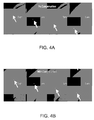
- FIGs. 4A and 4B This embodiment allows for the pristine use of the original image data. It should be further noted that additional transforms of subsurface targets may need to be provided to the surgeon to provide accurate path planning to target.
- FIG. 4A is a diagram that conceptually illustrates the process whereby an image slice from the transverse plane through a liver is polled based on a mapping obtained without any adjustments, that is, the alignment provided by 104.
- FIGs. 4B is a diagram that conceptually illustrates the process whereby an image slice from the transverse plane through a liver is polled based on the non-rigid of FIG. 2 and a local transform in accordance with an embodiment of the invention. For the purposes of simulating an IGS display in FIGs.
- a simulated stylus cursor is shown as being dragged across the liver in a medial to lateral direction on the physical patient, where the location of the stylus is shown on a transverse image as a dot with the arrow shown for location emphasis.
- FIG. 4A it can be seen that because of imperfections in alignment using purely a rigid transformation (step 104 of Fig. 1 ), a cursor can fall well off the organ (liver in this case) in image space as the stylus is dragged across and reaches the more lateral surface regions of the organ.
- a cursor position can be corrected such that it does not inaccurately report its position as being off the organ (liver in this case) in image, space but rather accurately portrays its location on the organ as the stylus is dragged across and reaches the more lateral surface regions of the organ.
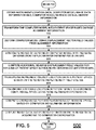
- FIG. 5 is a flow chart of steps in an exemplary method 500 for calculating a mapping adjustment for an instrument in image space in accordance with an embodiment of the invention.
- Method 500 begins at block 502 and proceeds to block 504.
- data sets for transforming an instrument in patient space to image space are obtained or received.
- a location of the instrument in patient space is received.
- a computer model of the non-rigid structure is received, along with deformation displacement vector field values and the correspondence function for computer model and surface data after the rigid alignment, such as the deformation displacement vector field values and initial correspondence function obtained in FIG. 2 .
- data associating the computer model and the image data is also received.
- the relationship between the nodes of the computer model and the voxels in the image data is received. Such a relationship can also be defined via an image/model correspondence function.
- the geometry of the computer model can be transformed in to patient space starting at block 506.
- the rigid alignment information can first be used to transform the locations of the nodes of the computer model in a computer model space to locations in patient space.
- the initial correspondence function can be used to map the deformed nodes into the patient space.
- the deformation displacement vector field values can be used to deform the computer model in patient space and thus provide a fit to the surface data in patient space. Consequently or in combination with the deformation or transformation of the locations of the nodes of computer model at block 508, the nodes of the computer model can also be associated with reverse deformation values at block 510 (i.e., the negative values of the deformation displacement vector field values received).
- the steps described above will be generally sufficient for enabling an IGS to place a cursor representing the location of an instrument/object in the proper location when the position of the instrument/object is within a portion of the non-rigid structure.
- the location would quickly revert back to essentially a rigid transformation. This can result in the cursor position jumping erratically as the instrument/object in moved.
- the various embodiments of the invention provide for calculating additional reverse misplace field values in regions of patient space surrounding the deformed computer model at block 512.
- Additional values can be computed by include solving a partial differential equation that describes the process of diffusion explicitly using a finite difference method on the natural voxel grid in patient space prior to the transformation of instrument location coordinates.
- all voxels associated with deformed computer model have undeforming vector displacements associated with them.
- the aforementioned diffusion method can be used whereby the medial-to-lateral displacements are fixed within the organ but allowed to numerically diffuse to create an envelope surrounding the computer model.
- an additional, small envelope of non-rigid transformations is defined in regions just outside the surfaces of the non-rigid structure.
- the envelope thus defines a region that smoothly transitions from the reverse flow field values of the deformed computer model in patient space and the rigid transforms elsewhere in patient space. Accordingly, if an instrument/object is located near the surface of the non-rigid structure, its transformation into the original computer model space will be based on the envelope rather than the rigid transformation. Thus, a mapping is generated to allow for a smooth local transform when a stylus/object is used within the IGS system both within and near the physical organ surface.
- the partial differential equation can be a diffusion equation.
- the invention is not limited in this regard and other types of partial differential equations or interpolative methods can be used to form the envelope in the various embodiments of the invention such as averaging schemes or a neighborhood functional form.
- transformation of the instrument/object location into image space can begin starting at block 514.
- Block 512 the reverse flow field values from block 508 and 512 are used to initially transform the coordinates of the instrument location in patient space.
- this location data for the instrument/object in patient space is further transformed into location data in computer model space. More specifically, the location of the instrument/object in physical space is transformed by the reverse displacement field. Once performed, the instrument/object location has been effectively undeformed.
- Block 516 can then apply the transform from patient-space to image-space, i.e. the rigid alignment transform associated with step 104 of FIG. 1 (or the appropriate rigid transform depending on the embodiment of FIG. 1 ). Once the transformations at blocks 514 and 516 are completed, coordinates for an instrument/object in image space are known and appropriate image data can be determined in block 518.
- the relationship between the deformed organ(s) in patient-space as captured by instrumentation can be used to adjust nodes of the computer model such that a complete path between the voxels of the image data and the location of the instrument/object can be derived for display in image space.
- the image data and indicia of the instrument/object location can be displayed during the IGS procedure.
- the image data and indicia for the instrument/object can be displayed in a two-dimensional or three-dimensional format.
- the instrument location in image space can be used to identify the appropriate cardinal image slices in the image guided display and the cursor position.
- the image data and cursor can be displayed at block 520.
- any and all other information expressed in the image space could be rendered with some relationship to the cursor.
- instrument/object location is important, the path or trajectory from the current location to a neighboring location is likely to be important.
- other objects or locations on the surface or nearby may need to be transformed to image-space to provide for accurate navigation.
- the transform steps could be modified such that the location/object and neighboring portions are deformed and rigidly transformed to their appropriate positions in image-space thus ensuring that when navigating from a current location to a neighboring location in physical space that the corresponding path image space is accurate.
- the method 500 then proceeds to block 520 to continue previous processing, including repeating method 500 when the instrument is moved.
- FIG. 6 shows an exemplary hardware system configuration 600 in accordance with an embodiment of the invention.
- system 600 can include an image/data processor 605, a display monitor 610, and an IGS controller 615.
- the IGS controller can be coupled to an optical tracking sensor which consists of sensing optical cameras 630, and emitters 620, 625, and 635. Further, the IGS controller 615 can be coupled to one or more emitters that can serve as instruments such as 620, and 635.
- the 640 is a separate computation node controller that interfaces to the image/data processor 605 for the purpose of non-rigid deformation correction and the embodiment of related processes
- the various components are shown as separate, discrete components, the invention is not limited in this regard.
- the IGS controller 615, the image data processor 605, and the computation node controller 640 can be integrated into a single system.
- the computation node controller 640 could be separated into multiple computation node controllers networked together.
- System 600 operates as follows. First, emitter 625 is often affixed to the patient or supporting surgical instrumentation. This could be replaced by providing a fixed camera mount (i.e. fix 630) within the operating room. Sensor 630 is used to determine the location of all emitters within the operating room (to include optimal stylus 620, or potentially a laser range scanner 635). Emitter 620, or 635 could be used to detect a surface, or visible structure of a non-rigid organ or the location of an instrument. However, the invention is not limited in this regard and more than one sensing system can be used to provide surface data and/or instrument/object position data.
- An example of a system for generating surface data is a laser-range scanner system, such as the RealScan 3D system produced by 3D Digital Corporation of Danbury, CT or a similar system custom designed by Pathfinder Therapeutics Inc. of Milwaukee, TN.
- Such systems are capable of capturing three-dimensional topographic surface data as well surface texture mapping using an array of data points. For example, in one embodiment a scanning field of 500 horizontal by 512 vertical points can be acquired in 5-10 seconds and used to generate surface data of exposed surfaces during IGS procedures.
- such a system can be tracked in the operating room space using a digitization system and calibrated using phantoms with separate independent digitization. 635 would represent the result of their use.
- texture map data generally facilitates the segmentation, i.e. extraction, of the liver surface for alignment to preoperative imaging.
- Other embodiments could use a tracked ultrasound probe which could acquire external and/or interior surface data. The data could be used to extract any number of boundary data to include external and/or interior surface structures for use in the alignment process.
- system 600 operates as follows. Prior to surgery, relevant data regarding the preoperative organ 102 would be transmitted to the computation node controller 640 or would have been processed on the controller 615. Upon collection of surface data from digitization equipment like that of 620 and 635, the image/data processor 605 transmits that data as well as any other relevant intraoperative information to the computation node controller 640. Using the computer model, the computation node controller 640 completes the rigid alignment of the computer model to the surface data, as described in PIG. 1, followed by the non-rigid alignment of the computer model to the surface data, as described in FIGs. 1 and 2 . Data/image processor 605 may also perform transformations on the data. As described above, a local transformation may also be required.
- the computation node controller 640 can generate such deformed and adjusted maps, as described above with respect to FIG. 5 .
- the map can then be used to perform IGS procedures either by transforming points on the computation node controller 640, or by providing the proper mapping function to the data/image processing unit 605 and allowing it to apply the proper transform for the IGS display 610.
- FIG. 6 An exemplary system was constructed, similar to that illustrated in FIG. 6 .
- a Stealth Model No. LPC-650-T9500-64GF-04G-6-E-00 Little PC (Computer) was configured to operate as the computation node controller 640.
- the controller was used to provide a rigid and non-rigid alignment of a computer model and surface data of a liver in accordance with an embodiment of the invention as well as the preoperative processing components associated with 102.
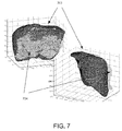
- FIG. 7 shows the results of an initial rigid alignment of the computer model 702 (black mesh) and surface data 704 (gray points). These results were obtained using a salient feature weighting registration method.
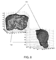
- FIG. 8 shows the results of a non-rigid alignment in accordance with an embodiment of the invention.
- the deformed computer model 802 (black mesh) now is in greater agreement with the points of the surface data 704 (gray points).
- the execution of the realization and result shown in data 704 represents a mean closest point distance between the model and surface data of 4.7 +/- 3.0 mm prior to correction on the computation node controller. After the computation node controller execution of the invention reported herein, the closest point distance became 1.5 +/-0.8 mm.
- the amount of deformation of the computer model is shown in FIG. 9 , where the original computer model data and the deformed computer model data are overlaid. In FIG. 9 , the original computer model 702 is shown by the gray mesh and the deformed computer model is shown by the black mesh.
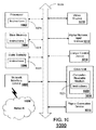
- FIG. 10 is a schematic diagram of a computer system 1000 for executing a set of instructions that, when executed, can cause the computer system to perform one or more of the methodologies and procedures described above.
- the architecture of computer system 1000 can be used to describe the architecture of one or more components of FIG. 6 .
- the computer system 1000 operates as a standalone device.
- the computer system 1000 can be connected (e.g., using a network) to other computing devices.
- the computer system 1000 can operate in the capacity of a server or a client developer machine in server-client developer network environment, or as a peer machine in a peer-to-peer (or distributed) network environment.
- the system could be a plug-in card to the guidance system.
- the machine can comprise various types of computing systems and devices, including a server computer, a client user computer, a personal computer (PC), a tablet PC, a laptop computer, a desktop computer, a control system, a network router, switch or bridge, or any other device capable of executing a set of instructions (sequential or otherwise) that specifies actions to be taken by that device. It is to be understood that a device of the present disclosure also includes any electronic device that provides voice, video or data communication. Further, while a single computer is illustrated, the phrase "computer system" shall be understood to include any collection of computing devices that individually or jointly execute a set (or multiple sets) of instructions to perform any one or more of the methodologies discussed herein.
- the computer system 1000 can include a processor 1002 (such as a central processing unit (CPU), a graphics processing unit (GPU, or both), a main memory 1004 and a static memory 1006, which communicate with each other via a bus 1008.
- the computer system 1000 can further include a display unit 1010, such as a video display (e.g., a liquid crystal display or LCD), a flat panel, a solid state display, or a cathode ray tube (CRT)).
- a video display e.g., a liquid crystal display or LCD
- flat panel e.g., a flat panel
- solid state display e.g., a solid state display
- CRT cathode ray tube
- the computer system 1000 can include an input device 1012 (e.g., a keyboard), a cursor control device 1014 (e.g., a mouse), a disk drive unit 1016, a signal generation device 1018 (e.g., a speaker or remote control) and a network interface device 1020.
- an input device 1012 e.g., a keyboard
- a cursor control device 1014 e.g., a mouse
- a disk drive unit 1016 e.g., a disk drive unit 1016
- a signal generation device 1018 e.g., a speaker or remote control
- the disk drive unit 1016 can include a computer-readable storage medium 1022 on which is stored one or more sets of instructions 1024 (e.g., software code) configured to implement one or more of the methodologies, procedures, or functions described herein.
- the instructions 1024 can also reside, completely or at least partially, within the main memory 1004, the static memory 1006, and/or within the processor 1002 during execution thereof by the computer system 1000.
- the main memory 1004 and the processor 1002 also can constitute machine-readable media.
- Dedicated hardware implementations including, but not limited to, application-specific integrated circuits, programmable logic arrays, and other hardware devices can likewise be constructed to implement the methods described herein.
- Applications that can include the apparatus and systems of various embodiments broadly include a variety of electronic and computer systems. Some embodiments implement functions in two or more specific interconnected hardware modules or devices with related control and data signals communicated between and through the modules, or as portions of an application-specific integrated circuit.
- the exemplary system is applicable to software, firmware, and hardware implementations.
- the methods described herein can be stored as software programs in a computer-readable storage medium and can be configured for running on a computer processor.
- software implementations can include, but are not limited to, distributed processing, component/object distributed processing, parallel processing, virtual machine processing, which can also be constructed to implement the methods described herein.
- the present disclosure contemplates a computer-readable storage medium containing instructions 1024 or that receives and executes instructions 1024 from a propagated signal so that a device connected to a network environment 1026 can send or receive voice and/or video data, and that can communicate over the network 1026 using the instructions 1024.
- the instructions 1024 can further be transmitted or received over a network 1026 via the network interface device 1020.
- While the computer-readable storage medium 1022 is shown in an exemplary embodiment to be a single storage medium, the term “computer-readable storage medium” should be taken to include a single medium or multiple media (e.g., a centralized or distributed database, and/or associated caches and servers) that store the one or more sets of instructions.
- the term “computer-readable storage medium” shall also be taken to include any device that is capable of storing a set of instructions for execution by the machine and that cause the machine to perform any one or more of the methodologies of the present disclosure.
- computer-readable medium shall accordingly be taken to include, but not be limited to, solid-state memories such as a memory card or other package that houses one or more read-only (non-volatile) memories, random access memories, or other re-writable (volatile) memories; magneto-optical or optical medium such as a disk or tape; as well as carrier wave signals such as a signal embodying computer instructions in a transmission medium; and/or a digital file attachment to e-mail or other self-contained information archive or set of archives considered to be a distribution medium equivalent to a tangible storage medium. Accordingly, the disclosure is considered to include any one or more of a computer-readable medium or a distribution medium, as listed herein and to include recognized equivalents and successor media, in which the software implementations herein are stored.
Landscapes
- Engineering & Computer Science (AREA)
- Physics & Mathematics (AREA)
- General Physics & Mathematics (AREA)
- Theoretical Computer Science (AREA)
- Computer Vision & Pattern Recognition (AREA)
- Geometry (AREA)
- Software Systems (AREA)
- Computer Graphics (AREA)
- Apparatus For Radiation Diagnosis (AREA)
- Processing Or Creating Images (AREA)
- Magnetic Resonance Imaging Apparatus (AREA)
- Measuring And Recording Apparatus For Diagnosis (AREA)
- Image Processing (AREA)
Applications Claiming Priority (2)
| Application Number | Priority Date | Filing Date | Title |
|---|---|---|---|
| US29733610P | 2010-01-22 | 2010-01-22 | |
| PCT/US2011/021990 WO2011091218A1 (en) | 2010-01-22 | 2011-01-21 | System and method for correcting data for deformations during image-guided procedures |
Publications (2)
| Publication Number | Publication Date |
|---|---|
| EP2526525A1 EP2526525A1 (en) | 2012-11-28 |
| EP2526525B1 true EP2526525B1 (en) | 2016-05-04 |
Family
ID=44310188
Family Applications (1)
| Application Number | Title | Priority Date | Filing Date |
|---|---|---|---|
| EP11706049.1A Not-in-force EP2526525B1 (en) | 2010-01-22 | 2011-01-21 | System and method for correcting data for deformations during image-guided procedures |
Country Status (9)
| Country | Link |
|---|---|
| US (2) | US9767573B2 (enExample) |
| EP (1) | EP2526525B1 (enExample) |
| JP (1) | JP5978134B2 (enExample) |
| KR (1) | KR20120118479A (enExample) |
| CN (1) | CN102844789B (enExample) |
| AU (1) | AU2011207294A1 (enExample) |
| CA (1) | CA2786905A1 (enExample) |
| SG (1) | SG182591A1 (enExample) |
| WO (1) | WO2011091218A1 (enExample) |
Families Citing this family (25)
| Publication number | Priority date | Publication date | Assignee | Title |
|---|---|---|---|---|
| GB201003065D0 (en) * | 2010-02-23 | 2010-04-07 | Simpleware Ltd | Image processing method and method of three-dimensional printing incorporating the same |
| WO2012169990A2 (en) | 2010-05-04 | 2012-12-13 | Pathfinder Therapeutics, Inc. | System and method for abdominal surface matching using pseudo-features |
| JP5234671B2 (ja) * | 2010-05-19 | 2013-07-10 | ジーイー・メディカル・システムズ・グローバル・テクノロジー・カンパニー・エルエルシー | 超音波診断装置 |
| US10178955B2 (en) | 2012-08-06 | 2019-01-15 | Vanderbilt University | Enhanced method for correcting data for deformations during image guided procedures |
| WO2014093376A1 (en) * | 2012-12-10 | 2014-06-19 | The Cleveland Clinic Foundation | Mage fusion with automated compensation for brain deformation |
| GB2515510B (en) | 2013-06-25 | 2019-12-25 | Synopsys Inc | Image processing method |
| EP3443925B1 (en) * | 2014-05-14 | 2021-02-24 | Stryker European Holdings I, LLC | Processor arrangement for tracking the position of a work target |
| US10062167B2 (en) * | 2014-08-15 | 2018-08-28 | Toshiba Medical Systems Corporation | Estimated local rigid regions from dense deformation in subtraction |
| US11026750B2 (en) * | 2015-01-23 | 2021-06-08 | Queen's University At Kingston | Real-time surgical navigation |
| CN107209794B (zh) * | 2015-01-28 | 2022-02-08 | 皇家飞利浦有限公司 | 解剖结构的有限元建模 |
| EP3109824B1 (en) * | 2015-06-24 | 2019-03-20 | RaySearch Laboratories AB | System and method for handling image data |
| EP3795061B1 (en) | 2015-08-14 | 2025-12-03 | Intuitive Surgical Operations, Inc. | Systems and methods of registration for image-guided surgery |
| US11202680B2 (en) | 2015-08-14 | 2021-12-21 | Intuitive Surgical Operations, Inc. | Systems and methods of registration for image-guided surgery |
| US10743941B2 (en) * | 2015-11-24 | 2020-08-18 | Vanderbilt University | Method and system for trackerless image guided soft tissue surgery and applications of same |
| JP6676758B2 (ja) * | 2015-12-16 | 2020-04-08 | ブレインラボ アーゲー | 位置合わせ精度の決定 |
| US10467497B2 (en) * | 2016-02-22 | 2019-11-05 | Sony Corporation | System and method for providing assistance in surgery in presence of tissue deformation |
| US10426556B2 (en) * | 2016-06-01 | 2019-10-01 | Vanderbilt University | Biomechanical model assisted image guided surgery system and method |
| EP3300021B1 (en) * | 2016-09-22 | 2018-12-05 | RaySearch Laboratories AB | Image processing system and method for interactive contouring of three-dimensional medical data |
| US10089712B2 (en) * | 2016-09-30 | 2018-10-02 | Oracle International Corporation | System and method providing automatic alignment of aerial/satellite imagery to known ground features |
| KR101911630B1 (ko) | 2017-04-05 | 2018-10-24 | 한양대학교 산학협력단 | 안구의 전기 전도도 추정 방법 및 장치 |
| JP7040908B2 (ja) * | 2017-09-28 | 2022-03-23 | 日鉄鋼板株式会社 | サンドイッチパネル、及び壁ユニット |
| DE102019107952B4 (de) * | 2019-03-27 | 2023-08-10 | Volume Graphics Gmbh | Computer-implementiertes Verfahren zur Analyse von Messdaten eines Objekts |
| FR3104054B1 (fr) * | 2019-12-10 | 2022-03-25 | Capsix | Dispositif de definition d’une sequence de deplacements sur un modele generique |
| KR102370490B1 (ko) * | 2020-03-13 | 2022-03-04 | 숭실대학교 산학협력단 | 가상 객체의 변형에 따른 의료 영상의 변형 방법, 이를 수행하기 위한 기록 매체 및 장치 |
| CN112330603B (zh) * | 2020-10-19 | 2023-04-18 | 浙江省肿瘤医院 | 基于软组织表面形变估计组织内部目标运动的系统与方法 |
Family Cites Families (5)
| Publication number | Priority date | Publication date | Assignee | Title |
|---|---|---|---|---|
| JP4674948B2 (ja) * | 2000-09-29 | 2011-04-20 | オリンパス株式会社 | 手術ナビゲーション装置および手術ナビゲーション装置の作動方法 |
| US6584339B2 (en) | 2001-06-27 | 2003-06-24 | Vanderbilt University | Method and apparatus for collecting and processing physical space data for use while performing image-guided surgery |
| JP4636618B2 (ja) * | 2006-09-28 | 2011-02-23 | 学校法人早稲田大学 | シミュレーション装置及びこれを用いた手術用ロボットの制御システム、並びにシミュレーション装置用のプログラム |
| EP2081494B1 (en) * | 2006-11-16 | 2018-07-11 | Vanderbilt University | System and method of compensating for organ deformation |
| CN101675455B (zh) * | 2007-04-26 | 2016-11-09 | 皇家飞利浦电子股份有限公司 | 外科流程的风险指示 |
-
2011
- 2011-01-21 CN CN201180011392.6A patent/CN102844789B/zh not_active Expired - Fee Related
- 2011-01-21 CA CA2786905A patent/CA2786905A1/en not_active Abandoned
- 2011-01-21 US US13/574,624 patent/US9767573B2/en not_active Expired - Fee Related
- 2011-01-21 WO PCT/US2011/021990 patent/WO2011091218A1/en not_active Ceased
- 2011-01-21 SG SG2012053153A patent/SG182591A1/en unknown
- 2011-01-21 KR KR1020127021897A patent/KR20120118479A/ko not_active Withdrawn
- 2011-01-21 JP JP2012550138A patent/JP5978134B2/ja not_active Expired - Fee Related
- 2011-01-21 AU AU2011207294A patent/AU2011207294A1/en not_active Abandoned
- 2011-01-21 EP EP11706049.1A patent/EP2526525B1/en not_active Not-in-force
-
2017
- 2017-09-18 US US15/707,516 patent/US10776935B2/en active Active
Also Published As
| Publication number | Publication date |
|---|---|
| US9767573B2 (en) | 2017-09-19 |
| US10776935B2 (en) | 2020-09-15 |
| JP2013517840A (ja) | 2013-05-20 |
| AU2011207294A1 (en) | 2012-07-26 |
| SG182591A1 (en) | 2012-08-30 |
| US20180005391A1 (en) | 2018-01-04 |
| CA2786905A1 (en) | 2011-07-28 |
| US20120330635A1 (en) | 2012-12-27 |
| KR20120118479A (ko) | 2012-10-26 |
| WO2011091218A1 (en) | 2011-07-28 |
| JP5978134B2 (ja) | 2016-08-24 |
| EP2526525A1 (en) | 2012-11-28 |
| CN102844789B (zh) | 2017-05-03 |
| CN102844789A (zh) | 2012-12-26 |
Similar Documents
| Publication | Publication Date | Title |
|---|---|---|
| US10776935B2 (en) | System and method for correcting data for deformations during image-guided procedures | |
| JP6283672B2 (ja) | 画像誘導処置中の変形のためにデータを修正する向上された方法 | |
| US11605185B2 (en) | System and method for generating partial surface from volumetric data for registration to surface topology image data | |
| US8340379B2 (en) | Systems and methods for displaying guidance data based on updated deformable imaging data | |
| US8358818B2 (en) | Apparatus and methods of compensating for organ deformation, registration of internal structures to images, and applications of same | |
| US9498132B2 (en) | Visualization of anatomical data by augmented reality | |
| Özgür et al. | Preoperative liver registration for augmented monocular laparoscopy using backward–forward biomechanical simulation | |
| CN110458872B (zh) | 使用超声弹性成像执行生物力学驱动的图像配准的系统和方法 | |
| US11547488B2 (en) | Systems and methods for performing intraoperative image registration | |
| Modrzejewski et al. | An in vivo porcine dataset and evaluation methodology to measure soft-body laparoscopic liver registration accuracy with an extended algorithm that handles collisions | |
| US20180189966A1 (en) | System and method for guidance of laparoscopic surgical procedures through anatomical model augmentation | |
| EP1598778A1 (en) | Method for automatically mapping of geometric objects in digital medical images | |
| Haouchine et al. | Using contours as boundary conditions for elastic registration during minimally invasive hepatic surgery | |
| Espinel et al. | Using multiple images and contours for deformable 3d–2d registration of a preoperative ct in laparoscopic liver surgery | |
| Conley et al. | Image to physical space registration of supine breast MRI for image guided breast surgery | |
| Sioutis | Registration of prostate surfaces for image-guided robotic surgery via the da Vinci System |
Legal Events
| Date | Code | Title | Description |
|---|---|---|---|
| PUAI | Public reference made under article 153(3) epc to a published international application that has entered the european phase |
Free format text: ORIGINAL CODE: 0009012 |
|
| 17P | Request for examination filed |
Effective date: 20120822 |
|
| AK | Designated contracting states |
Kind code of ref document: A1 Designated state(s): AL AT BE BG CH CY CZ DE DK EE ES FI FR GB GR HR HU IE IS IT LI LT LU LV MC MK MT NL NO PL PT RO RS SE SI SK SM TR |
|
| DAX | Request for extension of the european patent (deleted) | ||
| 17Q | First examination report despatched |
Effective date: 20140530 |
|
| GRAP | Despatch of communication of intention to grant a patent |
Free format text: ORIGINAL CODE: EPIDOSNIGR1 |
|
| INTG | Intention to grant announced |
Effective date: 20151117 |
|
| GRAS | Grant fee paid |
Free format text: ORIGINAL CODE: EPIDOSNIGR3 |
|
| GRAA | (expected) grant |
Free format text: ORIGINAL CODE: 0009210 |
|
| AK | Designated contracting states |
Kind code of ref document: B1 Designated state(s): AL AT BE BG CH CY CZ DE DK EE ES FI FR GB GR HR HU IE IS IT LI LT LU LV MC MK MT NL NO PL PT RO RS SE SI SK SM TR |
|
| REG | Reference to a national code |
Ref country code: GB Ref legal event code: FG4D |
|
| REG | Reference to a national code |
Ref country code: CH Ref legal event code: EP |
|
| REG | Reference to a national code |
Ref country code: AT Ref legal event code: REF Ref document number: 797494 Country of ref document: AT Kind code of ref document: T Effective date: 20160515 |
|
| REG | Reference to a national code |
Ref country code: IE Ref legal event code: FG4D |
|
| REG | Reference to a national code |
Ref country code: DE Ref legal event code: R096 Ref document number: 602011026139 Country of ref document: DE |
|
| REG | Reference to a national code |
Ref country code: DE Ref legal event code: R082 Ref document number: 602011026139 Country of ref document: DE Representative=s name: SCHMITT-NILSON SCHRAUD WAIBEL WOHLFROM PATENTA, DE Ref country code: DE Ref legal event code: R082 Ref document number: 602011026139 Country of ref document: DE Representative=s name: MURGITROYD & COMPANY, DE Ref country code: DE Ref legal event code: R082 Ref document number: 602011026139 Country of ref document: DE |
|
| REG | Reference to a national code |
Ref country code: NL Ref legal event code: MP Effective date: 20160504 |
|
| REG | Reference to a national code |
Ref country code: LT Ref legal event code: MG4D |
|
| PG25 | Lapsed in a contracting state [announced via postgrant information from national office to epo] |
Ref country code: NO Free format text: LAPSE BECAUSE OF FAILURE TO SUBMIT A TRANSLATION OF THE DESCRIPTION OR TO PAY THE FEE WITHIN THE PRESCRIBED TIME-LIMIT Effective date: 20160804 Ref country code: FI Free format text: LAPSE BECAUSE OF FAILURE TO SUBMIT A TRANSLATION OF THE DESCRIPTION OR TO PAY THE FEE WITHIN THE PRESCRIBED TIME-LIMIT Effective date: 20160504 Ref country code: NL Free format text: LAPSE BECAUSE OF FAILURE TO SUBMIT A TRANSLATION OF THE DESCRIPTION OR TO PAY THE FEE WITHIN THE PRESCRIBED TIME-LIMIT Effective date: 20160504 Ref country code: LT Free format text: LAPSE BECAUSE OF FAILURE TO SUBMIT A TRANSLATION OF THE DESCRIPTION OR TO PAY THE FEE WITHIN THE PRESCRIBED TIME-LIMIT Effective date: 20160504 |
|
| REG | Reference to a national code |
Ref country code: AT Ref legal event code: MK05 Ref document number: 797494 Country of ref document: AT Kind code of ref document: T Effective date: 20160504 |
|
| PG25 | Lapsed in a contracting state [announced via postgrant information from national office to epo] |
Ref country code: RS Free format text: LAPSE BECAUSE OF FAILURE TO SUBMIT A TRANSLATION OF THE DESCRIPTION OR TO PAY THE FEE WITHIN THE PRESCRIBED TIME-LIMIT Effective date: 20160504 Ref country code: HR Free format text: LAPSE BECAUSE OF FAILURE TO SUBMIT A TRANSLATION OF THE DESCRIPTION OR TO PAY THE FEE WITHIN THE PRESCRIBED TIME-LIMIT Effective date: 20160504 Ref country code: SE Free format text: LAPSE BECAUSE OF FAILURE TO SUBMIT A TRANSLATION OF THE DESCRIPTION OR TO PAY THE FEE WITHIN THE PRESCRIBED TIME-LIMIT Effective date: 20160504 Ref country code: GR Free format text: LAPSE BECAUSE OF FAILURE TO SUBMIT A TRANSLATION OF THE DESCRIPTION OR TO PAY THE FEE WITHIN THE PRESCRIBED TIME-LIMIT Effective date: 20160805 Ref country code: PT Free format text: LAPSE BECAUSE OF FAILURE TO SUBMIT A TRANSLATION OF THE DESCRIPTION OR TO PAY THE FEE WITHIN THE PRESCRIBED TIME-LIMIT Effective date: 20160905 Ref country code: ES Free format text: LAPSE BECAUSE OF FAILURE TO SUBMIT A TRANSLATION OF THE DESCRIPTION OR TO PAY THE FEE WITHIN THE PRESCRIBED TIME-LIMIT Effective date: 20160504 Ref country code: LV Free format text: LAPSE BECAUSE OF FAILURE TO SUBMIT A TRANSLATION OF THE DESCRIPTION OR TO PAY THE FEE WITHIN THE PRESCRIBED TIME-LIMIT Effective date: 20160504 |
|
| PG25 | Lapsed in a contracting state [announced via postgrant information from national office to epo] |
Ref country code: IT Free format text: LAPSE BECAUSE OF FAILURE TO SUBMIT A TRANSLATION OF THE DESCRIPTION OR TO PAY THE FEE WITHIN THE PRESCRIBED TIME-LIMIT Effective date: 20160504 |
|
| PG25 | Lapsed in a contracting state [announced via postgrant information from national office to epo] |
Ref country code: EE Free format text: LAPSE BECAUSE OF FAILURE TO SUBMIT A TRANSLATION OF THE DESCRIPTION OR TO PAY THE FEE WITHIN THE PRESCRIBED TIME-LIMIT Effective date: 20160504 Ref country code: CZ Free format text: LAPSE BECAUSE OF FAILURE TO SUBMIT A TRANSLATION OF THE DESCRIPTION OR TO PAY THE FEE WITHIN THE PRESCRIBED TIME-LIMIT Effective date: 20160504 Ref country code: DK Free format text: LAPSE BECAUSE OF FAILURE TO SUBMIT A TRANSLATION OF THE DESCRIPTION OR TO PAY THE FEE WITHIN THE PRESCRIBED TIME-LIMIT Effective date: 20160504 Ref country code: SK Free format text: LAPSE BECAUSE OF FAILURE TO SUBMIT A TRANSLATION OF THE DESCRIPTION OR TO PAY THE FEE WITHIN THE PRESCRIBED TIME-LIMIT Effective date: 20160504 Ref country code: RO Free format text: LAPSE BECAUSE OF FAILURE TO SUBMIT A TRANSLATION OF THE DESCRIPTION OR TO PAY THE FEE WITHIN THE PRESCRIBED TIME-LIMIT Effective date: 20160504 |
|
| REG | Reference to a national code |
Ref country code: DE Ref legal event code: R097 Ref document number: 602011026139 Country of ref document: DE |
|
| PG25 | Lapsed in a contracting state [announced via postgrant information from national office to epo] |
Ref country code: SM Free format text: LAPSE BECAUSE OF FAILURE TO SUBMIT A TRANSLATION OF THE DESCRIPTION OR TO PAY THE FEE WITHIN THE PRESCRIBED TIME-LIMIT Effective date: 20160504 Ref country code: PL Free format text: LAPSE BECAUSE OF FAILURE TO SUBMIT A TRANSLATION OF THE DESCRIPTION OR TO PAY THE FEE WITHIN THE PRESCRIBED TIME-LIMIT Effective date: 20160504 Ref country code: BE Free format text: LAPSE BECAUSE OF FAILURE TO SUBMIT A TRANSLATION OF THE DESCRIPTION OR TO PAY THE FEE WITHIN THE PRESCRIBED TIME-LIMIT Effective date: 20160504 Ref country code: AT Free format text: LAPSE BECAUSE OF FAILURE TO SUBMIT A TRANSLATION OF THE DESCRIPTION OR TO PAY THE FEE WITHIN THE PRESCRIBED TIME-LIMIT Effective date: 20160504 |
|
| PLBE | No opposition filed within time limit |
Free format text: ORIGINAL CODE: 0009261 |
|
| STAA | Information on the status of an ep patent application or granted ep patent |
Free format text: STATUS: NO OPPOSITION FILED WITHIN TIME LIMIT |
|
| 26N | No opposition filed |
Effective date: 20170207 |
|
| PG25 | Lapsed in a contracting state [announced via postgrant information from national office to epo] |
Ref country code: SI Free format text: LAPSE BECAUSE OF FAILURE TO SUBMIT A TRANSLATION OF THE DESCRIPTION OR TO PAY THE FEE WITHIN THE PRESCRIBED TIME-LIMIT Effective date: 20160504 |
|
| REG | Reference to a national code |
Ref country code: DE Ref legal event code: R082 Ref document number: 602011026139 Country of ref document: DE Representative=s name: MURGITROYD & COMPANY, DE |
|
| REG | Reference to a national code |
Ref country code: CH Ref legal event code: PL |
|
| GBPC | Gb: european patent ceased through non-payment of renewal fee |
Effective date: 20170121 |
|
| PG25 | Lapsed in a contracting state [announced via postgrant information from national office to epo] |
Ref country code: MC Free format text: LAPSE BECAUSE OF FAILURE TO SUBMIT A TRANSLATION OF THE DESCRIPTION OR TO PAY THE FEE WITHIN THE PRESCRIBED TIME-LIMIT Effective date: 20160504 |
|
| REG | Reference to a national code |
Ref country code: FR Ref legal event code: ST Effective date: 20170929 |
|
| PG25 | Lapsed in a contracting state [announced via postgrant information from national office to epo] |
Ref country code: LI Free format text: LAPSE BECAUSE OF NON-PAYMENT OF DUE FEES Effective date: 20170131 Ref country code: FR Free format text: LAPSE BECAUSE OF NON-PAYMENT OF DUE FEES Effective date: 20170131 Ref country code: CH Free format text: LAPSE BECAUSE OF NON-PAYMENT OF DUE FEES Effective date: 20170131 |
|
| REG | Reference to a national code |
Ref country code: IE Ref legal event code: MM4A |
|
| PG25 | Lapsed in a contracting state [announced via postgrant information from national office to epo] |
Ref country code: GB Free format text: LAPSE BECAUSE OF NON-PAYMENT OF DUE FEES Effective date: 20170121 Ref country code: LU Free format text: LAPSE BECAUSE OF NON-PAYMENT OF DUE FEES Effective date: 20170121 |
|
| PG25 | Lapsed in a contracting state [announced via postgrant information from national office to epo] |
Ref country code: IE Free format text: LAPSE BECAUSE OF NON-PAYMENT OF DUE FEES Effective date: 20170121 |
|
| REG | Reference to a national code |
Ref country code: DE Ref legal event code: R082 Ref document number: 602011026139 Country of ref document: DE Representative=s name: MURGITROYD & COMPANY, DE |
|
| PG25 | Lapsed in a contracting state [announced via postgrant information from national office to epo] |
Ref country code: MT Free format text: LAPSE BECAUSE OF NON-PAYMENT OF DUE FEES Effective date: 20170121 |
|
| PG25 | Lapsed in a contracting state [announced via postgrant information from national office to epo] |
Ref country code: AL Free format text: LAPSE BECAUSE OF FAILURE TO SUBMIT A TRANSLATION OF THE DESCRIPTION OR TO PAY THE FEE WITHIN THE PRESCRIBED TIME-LIMIT Effective date: 20160504 |
|
| PG25 | Lapsed in a contracting state [announced via postgrant information from national office to epo] |
Ref country code: HU Free format text: LAPSE BECAUSE OF FAILURE TO SUBMIT A TRANSLATION OF THE DESCRIPTION OR TO PAY THE FEE WITHIN THE PRESCRIBED TIME-LIMIT; INVALID AB INITIO Effective date: 20110121 |
|
| PG25 | Lapsed in a contracting state [announced via postgrant information from national office to epo] |
Ref country code: BG Free format text: LAPSE BECAUSE OF FAILURE TO SUBMIT A TRANSLATION OF THE DESCRIPTION OR TO PAY THE FEE WITHIN THE PRESCRIBED TIME-LIMIT Effective date: 20160504 |
|
| PG25 | Lapsed in a contracting state [announced via postgrant information from national office to epo] |
Ref country code: CY Free format text: LAPSE BECAUSE OF NON-PAYMENT OF DUE FEES Effective date: 20160504 |
|
| PG25 | Lapsed in a contracting state [announced via postgrant information from national office to epo] |
Ref country code: MK Free format text: LAPSE BECAUSE OF FAILURE TO SUBMIT A TRANSLATION OF THE DESCRIPTION OR TO PAY THE FEE WITHIN THE PRESCRIBED TIME-LIMIT Effective date: 20160504 |
|
| PG25 | Lapsed in a contracting state [announced via postgrant information from national office to epo] |
Ref country code: TR Free format text: LAPSE BECAUSE OF FAILURE TO SUBMIT A TRANSLATION OF THE DESCRIPTION OR TO PAY THE FEE WITHIN THE PRESCRIBED TIME-LIMIT Effective date: 20160504 |
|
| PGFP | Annual fee paid to national office [announced via postgrant information from national office to epo] |
Ref country code: DE Payment date: 20200129 Year of fee payment: 10 |
|
| PG25 | Lapsed in a contracting state [announced via postgrant information from national office to epo] |
Ref country code: IS Free format text: LAPSE BECAUSE OF FAILURE TO SUBMIT A TRANSLATION OF THE DESCRIPTION OR TO PAY THE FEE WITHIN THE PRESCRIBED TIME-LIMIT Effective date: 20160904 |
|
| REG | Reference to a national code |
Ref country code: DE Ref legal event code: R119 Ref document number: 602011026139 Country of ref document: DE |
|
| PG25 | Lapsed in a contracting state [announced via postgrant information from national office to epo] |
Ref country code: DE Free format text: LAPSE BECAUSE OF NON-PAYMENT OF DUE FEES Effective date: 20210803 |