EP2525705B1 - Nichtinvasives spektrometer und zugehöriges verfahren - Google Patents
Nichtinvasives spektrometer und zugehöriges verfahren Download PDFInfo
- Publication number
- EP2525705B1 EP2525705B1 EP11701559.4A EP11701559A EP2525705B1 EP 2525705 B1 EP2525705 B1 EP 2525705B1 EP 11701559 A EP11701559 A EP 11701559A EP 2525705 B1 EP2525705 B1 EP 2525705B1
- Authority
- EP
- European Patent Office
- Prior art keywords
- eye
- light
- illumination
- directly
- returning
- Prior art date
- Legal status (The legal status is an assumption and is not a legal conclusion. Google has not performed a legal analysis and makes no representation as to the accuracy of the status listed.)
- Not-in-force
Links
- 238000000034 method Methods 0.000 title claims description 12
- 238000005286 illumination Methods 0.000 claims description 66
- 230000003287 optical effect Effects 0.000 claims description 33
- 210000001525 retina Anatomy 0.000 claims description 26
- 238000005259 measurement Methods 0.000 claims description 23
- 238000012544 monitoring process Methods 0.000 claims description 20
- 210000000695 crystalline len Anatomy 0.000 claims description 15
- 241001465754 Metazoa Species 0.000 claims description 14
- 238000007689 inspection Methods 0.000 claims description 14
- 238000004458 analytical method Methods 0.000 claims description 12
- 210000000554 iris Anatomy 0.000 claims description 9
- 210000004127 vitreous body Anatomy 0.000 claims description 7
- 210000004087 cornea Anatomy 0.000 claims description 6
- 210000001742 aqueous humor Anatomy 0.000 claims description 5
- 210000002159 anterior chamber Anatomy 0.000 claims description 4
- 238000002835 absorbance Methods 0.000 claims description 3
- 210000001747 pupil Anatomy 0.000 description 32
- 239000000306 component Substances 0.000 description 7
- 230000008901 benefit Effects 0.000 description 6
- 239000008280 blood Substances 0.000 description 5
- 210000004369 blood Anatomy 0.000 description 5
- 230000000694 effects Effects 0.000 description 4
- 210000004027 cell Anatomy 0.000 description 3
- 239000013307 optical fiber Substances 0.000 description 3
- 239000000126 substance Substances 0.000 description 3
- 200000000007 Arterial disease Diseases 0.000 description 2
- 230000017531 blood circulation Effects 0.000 description 2
- 210000004556 brain Anatomy 0.000 description 2
- 239000000470 constituent Substances 0.000 description 2
- 238000001914 filtration Methods 0.000 description 2
- 238000010438 heat treatment Methods 0.000 description 2
- 230000008569 process Effects 0.000 description 2
- 230000004044 response Effects 0.000 description 2
- 230000002207 retinal effect Effects 0.000 description 2
- 230000000007 visual effect Effects 0.000 description 2
- LFQSCWFLJHTTHZ-UHFFFAOYSA-N Ethanol Chemical compound CCO LFQSCWFLJHTTHZ-UHFFFAOYSA-N 0.000 description 1
- 206010027646 Miosis Diseases 0.000 description 1
- 241000699670 Mus sp. Species 0.000 description 1
- 238000001069 Raman spectroscopy Methods 0.000 description 1
- 238000000862 absorption spectrum Methods 0.000 description 1
- 230000009471 action Effects 0.000 description 1
- 230000004913 activation Effects 0.000 description 1
- 210000001367 artery Anatomy 0.000 description 1
- 230000005540 biological transmission Effects 0.000 description 1
- 239000012503 blood component Substances 0.000 description 1
- 210000004204 blood vessel Anatomy 0.000 description 1
- 230000001413 cellular effect Effects 0.000 description 1
- 230000008859 change Effects 0.000 description 1
- 206010012601 diabetes mellitus Diseases 0.000 description 1
- 230000004069 differentiation Effects 0.000 description 1
- 230000000916 dilatatory effect Effects 0.000 description 1
- 230000010339 dilation Effects 0.000 description 1
- 201000010099 disease Diseases 0.000 description 1
- 208000037265 diseases, disorders, signs and symptoms Diseases 0.000 description 1
- 230000000763 evoking effect Effects 0.000 description 1
- 238000002594 fluoroscopy Methods 0.000 description 1
- 238000003384 imaging method Methods 0.000 description 1
- 230000006872 improvement Effects 0.000 description 1
- 238000001727 in vivo Methods 0.000 description 1
- 230000000266 injurious effect Effects 0.000 description 1
- 239000007788 liquid Substances 0.000 description 1
- 230000002503 metabolic effect Effects 0.000 description 1
- 230000001575 pathological effect Effects 0.000 description 1
- 238000001055 reflectance spectroscopy Methods 0.000 description 1
- 238000000985 reflectance spectrum Methods 0.000 description 1
- 210000001210 retinal vessel Anatomy 0.000 description 1
- 238000005070 sampling Methods 0.000 description 1
- 238000002798 spectrophotometry method Methods 0.000 description 1
- 238000004611 spectroscopical analysis Methods 0.000 description 1
- 230000003068 static effect Effects 0.000 description 1
- 238000002211 ultraviolet spectrum Methods 0.000 description 1
- 210000003462 vein Anatomy 0.000 description 1
- 208000037997 venous disease Diseases 0.000 description 1
- XLYOFNOQVPJJNP-UHFFFAOYSA-N water Substances O XLYOFNOQVPJJNP-UHFFFAOYSA-N 0.000 description 1
Images


Classifications
-
- A—HUMAN NECESSITIES
- A61—MEDICAL OR VETERINARY SCIENCE; HYGIENE
- A61B—DIAGNOSIS; SURGERY; IDENTIFICATION
- A61B3/00—Apparatus for testing the eyes; Instruments for examining the eyes
- A61B3/10—Objective types, i.e. instruments for examining the eyes independent of the patients' perceptions or reactions
- A61B3/11—Objective types, i.e. instruments for examining the eyes independent of the patients' perceptions or reactions for measuring interpupillary distance or diameter of pupils
-
- A—HUMAN NECESSITIES
- A61—MEDICAL OR VETERINARY SCIENCE; HYGIENE
- A61B—DIAGNOSIS; SURGERY; IDENTIFICATION
- A61B5/00—Measuring for diagnostic purposes; Identification of persons
- A61B5/145—Measuring characteristics of blood in vivo, e.g. gas concentration or pH-value ; Measuring characteristics of body fluids or tissues, e.g. interstitial fluid or cerebral tissue
- A61B5/1455—Measuring characteristics of blood in vivo, e.g. gas concentration or pH-value ; Measuring characteristics of body fluids or tissues, e.g. interstitial fluid or cerebral tissue using optical sensors, e.g. spectral photometrical oximeters
- A61B5/14551—Measuring characteristics of blood in vivo, e.g. gas concentration or pH-value ; Measuring characteristics of body fluids or tissues, e.g. interstitial fluid or cerebral tissue using optical sensors, e.g. spectral photometrical oximeters for measuring blood gases
- A61B5/14555—Measuring characteristics of blood in vivo, e.g. gas concentration or pH-value ; Measuring characteristics of body fluids or tissues, e.g. interstitial fluid or cerebral tissue using optical sensors, e.g. spectral photometrical oximeters for measuring blood gases specially adapted for the eye fundus
Definitions
- the present invention relates to a non-invasive spectrophotometer, and related method in particular for use in the non-invasive inspection, measurement and/or monitoring of physical and physiological features of a human or animal subject's eye and/or bodily functions in vivo.
- the device and method relate, for example, to such inspection, measurement and monitoring that uses one or more light beams directed at, and returning from various parts of the subject's eye(s) to provide analysable data.
- the measurement and/or monitoring of the features and functions of a human or animal body can prove necessary in many different situations.
- Previously blood samples have been taken from the patient or animal and constituents have been measured by spectrophotometry. It is also known to measure the constituents in the blood of the patient or of the animal by bringing a spectrophotometer into contact with the patient or the animal, for example by using modified contact lens systems.
- the eye which is the only part of the body that is designed to transmit light, can therefore act as both a cuvette or an integrated sphere of a spectrophotometer differentiated by time.
- WO90/12534 describes apparatus for monitoring body functions by directing light into the eye and analysing the light returning there from. It also describes a pupillometer for measuring the size of the pupil.
- WO02/071932 describes an improvement to such apparatus in which an alignment means determines the position of the centre of the pupil using a pupillometer to assist in aligning the optical system directing light into the eye.
- GB2422660 discloses a system for imaging the retina arranged to measure diffuse light at the retina and requiring dilation of pupil size and employing an integrated sphere as part of a spectrophotometer.
- a device for use in non-invasive inspection, measurement and/or monitoring of a human or animal subject's eye having a first optical system which comprises a focusing means adaptable to focus light in a controlled and selective manner on a selected structure of the eye for direct and diffuse reflectance from the selected structure of the eye, illumination means for providing illumination light to be selectively directed by way of the focussing means onto the eye for direct and diffuse reflectance from the said selected structure and for providing the illumination light in one or more pulses, receiving means for receiving directly and diffusely reflected light returning from the eye as a result of illumination by the illumination light and the receiving means arranged to distinguish between the directly and diffusely reflected light returning from the eye serving as an integrating sphere and the directly and diffusely reflected light returning from the said selected structure by discriminating the reflected light with a threshold wavelength, wherein the threshold wavelength is 1400 nm, and arranged to record the returning directly and diffusely reflected light intermittently based on a selected timing relationship between the one or more
- the invention proves particularly advantageous insofar as it can be arranged to employ particular features of the eye as part of a spectrophotometer for the inspection and/or analysis or measurement and monitoring of an anatomical and physiological characteristics of the eye.
- the subject's eye, and various structural characteristics thereof can function as a cuvette when monitoring/analysis of the subject's eye by direct reflectance from selected structures within the posterior chamber of the eye is required while the invention advantageously has the option of inspection and monitoring of diffuse reflectance from within the posterior chamber of the eye when functioning as an integrated sphere.
- a method of non-invasive inspection measurement and/or monitoring of a human or animal subjects eye comprising selecting a structure of the eye to monitor, adapting a focusing means in a controlled and selective manner to focus light on the selected structure, selectively directing one or more pulses of illumination light onto the eye through the focusing means to produce direct and diffuse reflectance returning from the said selected structure, wherein a timing relationship between the one or more pulses of illumination light and the direct and diffuse reflectance is selected based on the selected structure, distinguishing between directly and diffusely reflected light returning from the eye serving as an integrating sphere and from the said selected structure by discriminating the reflected light with a threshold wavelength, wherein the threshold wavelength of 1400 nm, and recording the directly and diffusely reflected light returning from the eye as a result of such illumination, wherein the directly and diffusely reflected light is recorded intermittently based on the timing relationship relative to the one or more pulses so as to discriminate between the directly and diffusely directed light returning from the selected structure and other
- the device can therefore be arranged to provide one or more pulses of illumination light to illuminate features of the eye, and to record the returning light pulse of the illumination, such that direct and/or diffuse reflections from different parts of the eye, or the interior thereof can be specifically identified or discriminated against.
- the recording period may commence immediately at the end of the illumination pulse, or at a predetermined time period thereafter or may overlap with the end of the illumination pulse.
- the optical characteristics of structures within the eye can further be advantageously employed within the present invention.
- water within the vitreous humor acts to absorb wavelengths generally above 1400 nm and so this can advantageously be employed as a natural filter when considering the reflected light.
- the distance that the light travels between the lens and the retina at the back of the adult eye being approximately 48mm of viteous humor is an important aspect of this filter.
- any light received above 1400 nm can therefore only have arisen through direct or diffuse reflectance from other structures and not from the area of interest.
- any reflectance arising through use of the eye as an integrating sphere i.e. when considering diffuse reflectance, light of wavelengths above 1400 nm can be ignored and as such would not form a component part of the diffuse reflectance from the retina.
- the device and method of the present invention of the eye as an integrated sphere can therefore advantageously employ light of an appropriate selected wavelength having regard to the natural filtering capability of the liquid within the vitreous humor.
- the majority of the returning light can then be determined to be either light returning from the retina, preferably diffuse light which has undergone multiple reflections within the eye before exiting through the pupil, or light directly and or diffusely reflected from one or more specific features of the eye.
- the arrangement is preferably such that the illumination light reflected directly or diffusely by other parts of the eye is not processed, or alternatively it is only light reflected by specific features of the eye that is processed.
- the eye is then advantageously used as a cuvette and/or an integrating sphere and can serve to ensure that illumination of the eye is not affected by spatial, angular or polarisation changes in the illumination light. As will be described further below, this provides further significant advantages over known devices in which illumination and recording is carried out simultaneously and in which direct reflectance is discriminated against.
- an optical system employing the present invention may be provided by modifying a standard spectrophotometer to record pulsed or intermittent light signals.
- the general principles of using such spectrophotometric techniques are described in WO90/12534 as referred to above.
- the eye In the spectroscopy field, the eye is in effect the cuvette and /or the integrated sphere of the body, since it is the only part of the body that is designed to transmit light. Thus, measurement of the characteristics of light reflected from the eye can give an indication of physical and physiological characteristics of the eye and also of characteristics of bodily functions in general.
- the present invention enables the ability of the eye to act as both a cuvette and an integrating sphere at the same time..
- the device can comprise a second optical system for measuring the pupil size, e.g. by modifying a standard pupillometer, such as that described in US Patent No. 5,784,145 .
- a standard pupillometer such as that described in US Patent No. 5,784,145 .
- the general principles of using pupillometry in this context are described in the applicant's previous International Patent Applications Nos. WO90/12534 and WO02/071932 .
- the device is also provided with alignment means, such as that described in WO02/071932 , controllable either directly by, or independently of, the subject, for example by use of manually operated lever(s), button(s) joystick(s) and/or one or more computer mice.
- the alignment means provides a variable focus capability to the system and may optionally operate in an automatic way without personal intervention from either the subject or the clinician. Indeed, activation of such alignment may also be automatically initiated by the first optical system, once the location of the pupil has been determined. This is a particularly advantageous arrangement for achieving the required "focussing" of the present invention so as to direct the output light to that part of the eye requiring inspection or monitoring.
- the second optical system is adapted to determine the location of the edge(s) of the pupil(s), so as to allow calculation of the centre of the pupil(s).
- the second optical system may also be used to provide iris recognition to determine and record the identity of the subject.
- the illumination light be focussed in the plane of the pupil, in some embodiments, this need not be done and the light simply can be directed towards the eye so as to enter through the pupil and illuminate the retina. In this manner the amount of light illuminating the area of interest is controlled.
- a particular structural feature of the eye such as the cornea, aqueous humor, lens, iris, vitreous humor and/or retina.
- the first and second light systems can comprise one or more optical fibre(s) for transmitting light towards the eye(s).
- the optical fibre(s) can be arranged to function as both the light input means and the light receiving means.
- the first light system may be arranged to monitor the intensity of light of a selected wavelength returning from the retina of the eye.
- the first light system may be arranged to monitor the intensity of light of different wavelengths returning from one or more structures of the eye, thereby enabling an absorbance/reflectance characteristic of the structure e.g. the retina to be determined.
- the first and second optical systems may have parts in common.
- the first and second receiving means may be provided by the same unit.
- the first and second light systems may use the same processing means.
- the device of the present invention employs advantageously adaptable and accurate focusing means for directing the illumination light onto the desired structure forming part of the human or animal subject's eye so as to allow for the ready and accurate monitoring, measurement and/or analysis of the inherent characteristics of such structural element.
- a subject's eye as a cuvette and/or integrated sphere in the optical inspection, measurement and/or monitoring of one or more structures of the eye for the non-invasive inspection, measurement and/or monitoring of physiological and/or physical changes in structures within the eye.
- human or animal subject's bodily function used herein is intended to include the wide variety of different functions that a medical or veterinary practitioner may wish to non-invasively inspect, monitor or measure.
- it is intended to include the measurement and/or monitoring of any substances and changes in the blood of the retina and any biochemical (organic or inorganic) changes in the cells of the retina of the subject.
- any or all of these changes can be measured and/or monitored in conjunction with changes in the electrical, biochemical or pathological activity of the retina or of the brain, and in addition to changes in the physical and/or physiological changes within the eye.
- the term "light” as used herein is, unless otherwise specified, intended to include visible wavelengths and non-visible wavelengths such as infra-red, near infra-red and ultra-violet light, that are non-injurious to the eye and the structures contained within the eye.
- An advantage of using non-visible wavelengths in the cuvette for direct reflectance is that the pupil size does not change when the eye receives such wavelengths.
- For diffuse reflectance the converse is an advantage, visible light will cause constriction of the pupil and so enhance the efficiency of the eye as an integrated sphere.
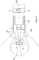
- a first optical system comprising a first light source 14 directing light to focussing means 15 mounted in a housing 12 for focussing light in a controllable and selective manner to any required structural feature and/or region of the eye.
- the selected feature is the lens 9 of the eye, although in the illustration of Fig. 3 , the feature is the iris 4or more specifically the plane of the pupil 13 (so illumination is independent of pupil size) and so as to direct the light onto the retina 10 of the eye.
- first receiving means 17 receives directly reflected light 16 returning from the lens 9 or other structures in the anterior chamber of the eye.
- Fig. 4 there is illustrated multiple reflection and scattering of the illumination light within the posterior chamber of the eye prior to the light emerging out of the pupil 13 and arising when the light output from the device is directed in the plane of the pupil 13 according to the illustration of Fig. 3 .
- the illuminating light can be directed to the retina 10 for direct reflectance there from, or diffuse reflectance if required and as illustrated in Fig. 4 .
- processing means 17A are provided for analysing the light that returns from the eye and as described in further detail below.
- the first light source 14 is arranged to provide one or more pulses of illumination light, preferably a stream of pulses
- the receiving/processing means 17 is arranged to record the frequency and/or intensity of light returning from the eye intermittently at a selected timing relative to said pulses so as to effectively discriminate between the light directly and diffusely reflected from different structures such as one or more of the cornea 7, iris 4 and lens 9 of the eye, or to discriminate between diffusely and directly reflected light as returned to the device.
- the light recorded is primarily recorded at a time or times when the light source 14 is not emitting light or is switched off. This may be achieved by intermittent actuation of the receiving means or appropriate sampling of the data received, e.g. by means of software.
- the eye is in effect being used selectively as a cuvette and/or integrating sphere for the monitoring of physiological and physical changes in all structures of the eye.
- the invention advantageously provides for a device and method in which the illuminating light can be accurately directed to a particular structure for a part of the human or animal subject's eye and which provides for direct and /or diffuse reflectance which can be analyzed in accordance with the present invention for inspection, measurement and/or monitoring of the physiological and/or physical characteristics, and if required changes thereof, of the subject's eye.
- direct reflectance from different surfaces within the eye such as the cornea, aqueous humor, lens, iris, vitreous humor and retina can be produced through the accurate control of the timing relationship between the illuminating and reflective light pulses. It is then readily possible to discriminate between direct reflectance returning from such various surface structures for subsequent analysis. Diffuse reflection from these structures would be separated via the second receiving means.
- the physiological and/or physical characteristics, and changes thereof, relating to such surface structures can therefore readily be inspected, measured and monitored and a further degree of discrimination can also be achieved through the selective use of the illuminating light of a particular wavelength.
- a timing relationship between the illuminating and reflected light pulses to readily discriminate between light returning through the action of the eye as an integrating sphere, i.e. monitoring measuring and inspection of diffuse reflectance, and through the use of the eye as a cuvette when analysis of only the direct reflectance is required.
- An integrating sphere is an ideal optical diffuser and is used, for example, in radiometric measurements, where uniform illumination is essential.
- Light input into an integrating sphere is uniformly reflected and scattered around the sphere's interior so the output is a uniform, spatially integrated beam which is insensitive to spatial, angular or polarisation changes in the input light.
- the light source/intensity is the same each time because the light s focussed in the plane of the pupil.
- the optical path is also constant for each individual eye. Beam movements can arise due to movement of components of the eye.
- the refractive index of the Cornea, Aqueous Humor, Lens and Vitreous Humor remain the same for each individual eye as does the air path.
- Integrating spheres are usually designed so there is not a direct path from the input to the output thereof.
- the input and output are thus usually located at different positions and baffles provided to block direct paths there between.
- the present invention benefits from the realisation that the eye itself can be used either as a cuvette or integrating sphere so that measurements taken by the device are not subject to variations in the light source.
- the eye only has a single input/output port, i.e. the pupil, and as light has to pass through reflective interface to enter the eye through the pupil, means have to be found to prevent input light which is reflected directly or diffusely back by these interfaces from swamping the diffuse light which has undergone reflection within the eye or of course vice versa.
- the present invention achieves this by the use of pulsed illumination and the selected timing of intermittent recording of light returning from the eye relative to the illumination pulses, and also through selective use of light of determined wavelengths so as to benefit from the natural filtering characteristics of the eye and its various component structures.
- a further significant advantage of using pulsed illumination light is that this helps reduce problems, e.g. due to heating, which can arise if the retina receives too much illumination from the light source 14. Heating can alter the properties of the blood as well as cellular and metabolic activity and may cause damage to the eye.
- the use of steady, continuous illumination whilst enabling measurements to be made in carefully controlled conditions, e.g. in a laboratory, may preclude use in a practical device, particularly if measurements need to be taken frequently, e.g. several times a day.
- the pulsatable component i.e. variation in the quantity being sensed due to the pulsing blood flow in the blood vessels of the retina, can be reduced or eliminated.
- the prior art which illustrates the retina continuously has to provide complex systems for recording measurements in time with the pulses in the blood flow to eliminate the pulsatable component.
- each pulse of illumination and the wavelength used will differ in dependence upon the substance or reaction to be measured.
- each illumination pulse may last between 0.1 milliseconds and a few seconds.
- the interval between illumination pulses will also depend on the substance or reaction being measured but, typically, would also be in the range 0.1 milliseconds to several seconds.
- the eye is preferably illuminated by a train of at least six pulses, and preferably more, with a measurement being recorded after each pulse and a mean and standard deviation calculated.
- time intervals can be employed:
- the relationship between the pulses is advantageously selected and controlled as required so as to differentiate between different directly and diffusely reflected pulses and also to discriminate between directly reflected and diffusely reflected light pulses as discussed above.
- the first optical system may be self-supporting and so can be part of apparatus in front of which the subject is located.
- the subject positions their eye so as to receive the illumination light.
- a flexible cowl 12A is provided around the housing 12 against which the subject can rest his eye.
- the cowl 12A may also serve to exclude extraneous light from the eye where the ambient light includes frequencies that are being monitored.
- cowls are well-known on other optical instruments e.g. around the lens of a telescope or pair of binoculars.
- the cowling also helps locate the subject's eye relative to the device and so defines the distance between the device and the subject's eye.
- a second optical system may be used to locate the centre of the pupil 13, and alignment means (not shown) used to align the illumination light from the first optical system so that light is shone through the centre of the pupil 13 in the plane of the pupil 13, that is in a Maxwellian view.
- the alignment process can be effected, for example, by means of a joystick (not shown), which can be operated by the physician, or the subject themselves. In this way, the operator can view an image of the eye being investigated on a screen (not shown) and use the joystick to align the first optical system with the centre of the pupil 13. Further details of this alignment process are known from WO90/12534 so will not be described further.
- the device may also be arranged such that the second optical system operates automatically (i.e. with manual operation).
- the second optical system may directly activate the alignment means to position the first optical system into the required alignment with the pupil.
- the image may be transferred directly onto the retina or required structure of the operator, for example by way of the first optical system itself.
- input light 14 is directed via an optical fibre 20 from which it is emitted so as to pass through focussing means 15 towards the desired site within the structure of the eye whether at the front or back of the eye as noted herein.
- the light is focussed on the lens for direct or diffuse reflectance there from
- Fig. 3 the light is focussed at the centre of the pupil 13 for direct and diffuse reflectance from the retina 10 and so as to be reflected back as illustrated in Fig. 4 .
- Light 16 which returns from the eye back through the pupil 13, subsequently passes back into the device and travels as a beam along one or more optical fibres 21 to the receiving means 17.
- the processing means 17A analyses the beam, e.g. to determine the absorbance/reflectance spectrum of the retina and/or the retinal blood vessels.
- Any combination of mono-chromatic light or white light, as well as wavelengths in the infra-red, near infra-red or ultra-violet spectra can be used.
- specific selected wavelengths permit optimal discrimination of, for example physical and physiological characteristics of the eye and any changes thereof in addition, if required, to the various blood components, as well as optimal discrimination of the various retinal biochemical functions and components.
- Figs. 5 and 6 correspond to Fig 1-4 but show a device in which part of the optical system is mounted on a scleral contact lens 30.
- the use of such a lens 30 to support the device is described further in WO90/12534 .
- Portions 30A of the contact lens extending beyond housing 31 may be coloured black if it is desirable to exclude extraneous light from entering the device.
- the operation of the device shown in Figs. 5 and 6 is otherwise similar to that shown in Figs. 1 to 4 .
- the illumination means 40 and receiving means 41 may be located remotely from the eye but positioned to direct illumination into the eye and receiving light returning there from. Processing means 41A is also shown. In this embodiment, the illumination light need not be focussed in the plane of the pupil but simply directed into the eye.
- the system described above can be used for a wide range of applications relating to physiological and physical characteristics of the human or animal eye.
- the illumination and recording of light may be used in a variety of analysis methods, e.g. to monitor the absorbance of specific wavelengths, to carry out diffuse reflectance spectroscopy, to carry out Raman spectroscopy (in which the illuminating light stimulates light emission from the eye which is then detected) or fluoroscopy or use of frequencies in the terahertz range.
- a monocular system can be used as part of a cash-dispensing machine, in which the identity of the person wishing to withdraw cash is checked via non-invasive DNA analysis of the retinal cells or other cells in any of the structures of the eye.
- the second optical system may be used to identify the subject by iris identification.
- Identification of the subject in this may be used for security and/or legal reasons. It may also be used by the processing means 17A to associate the subject's identity with the measurements being taken for recording purposes.
- the system can measure visual evoked potentials more accurately than conventional means, because it is possible to give an accurate amount of light and so the amplitude of response can also be assessed. Conventionally, by contrast, only latency of response is measured.
- the present system allows for the assessment of any electrical activity of the retina, so that the activity of the visual areas of the brain can be assessed.
- the measurements made possible with the present system can be of static samples or of continuous samples in real time.
- the present invention advantageously employs the anatomical and physiological characteristics of the eye to enhance the efficiency and accuracy with which the eye can be employed as a component of a spectrophotometer.
- the invention further allows for the advantageous differentiation between reflectance of illuminating light from the cornea, iris, lens, aqueous humor, vitreous humor and also the retina and so it becomes readily imposable to investigate changes in reflectance from any or all of these structures.
- the invention is not restricted to the details of a specific embodiment noted above and any appropriate number of light sources and receivers, for example two of each can be employed as required.
- the focussing system employed within the device of the present invention can advantageously be moved forwards and backwards all quadrants to focus the light as appropriate on any particular structure and, if required, in the plane of the pupil.
- Any data received from the reflected light can be analysed within the device or transmitted remotely therefrom by any appropriate wire or wireless, transmission means.
- the light employed within the present invention can be polarized as required and provided at any appropriate wavelength.
Landscapes
- Life Sciences & Earth Sciences (AREA)
- Health & Medical Sciences (AREA)
- Medical Informatics (AREA)
- Animal Behavior & Ethology (AREA)
- Ophthalmology & Optometry (AREA)
- Engineering & Computer Science (AREA)
- Biomedical Technology (AREA)
- Heart & Thoracic Surgery (AREA)
- Physics & Mathematics (AREA)
- Molecular Biology (AREA)
- Surgery (AREA)
- Biophysics (AREA)
- General Health & Medical Sciences (AREA)
- Public Health (AREA)
- Veterinary Medicine (AREA)
- Investigating Or Analysing Materials By Optical Means (AREA)
- Eye Examination Apparatus (AREA)
- Measurement Of The Respiration, Hearing Ability, Form, And Blood Characteristics Of Living Organisms (AREA)
- Cleaning By Liquid Or Steam (AREA)
Claims (12)
- Vorrichtung zur Verwendung bei der nichtinvasiven Untersuchung, Messung und/oder Beobachtung eines Auges eines menschlichen oder tierischen Versuchsobjekts, wobei die Vorrichtung ein erstes optisches System aufweist, das Folgendes umfasst: ein Fokussiermittel (15), das dazu angepasst werden kann, Licht zur direkten und diffusen Reflexion von einer ausgewählten Struktur (9) des Auges auf kontrollierte und selektive Weise auf die ausgewählte Struktur (9) des Auges zu fokussieren, ein Beleuchtungsmittel (14) zum Bereitstellen von Beleuchtungslicht, um mittels des Fokussierungsmittels (15) zur direkten und diffusen Reflexion von der ausgewählten Struktur selektiv auf das Auge gerichtet zu werden und zum Bereitstellen des Beleuchtungslichts in einem oder mehreren Impulsen, ein Empfangsmittel (17) zum Empfangen von direkt und diffus reflektiertem Licht, das als Folge der Beleuchtung mit dem Beleuchtungslicht von dem Auge zurückkehrt, wobei das Empfangsmittel (17) dazu eingerichtet ist, zwischen dem von dem als Ulbrichtkugel dienenden Auge zurückkehrenden direkt und diffus reflektierten Licht und dem von der ausgewählten Struktur (9) zurückkehrenden direkt und diffus reflektierten Licht zu unterscheiden, indem es das reflektierte Licht mit einer Grenzwellenlänge diskriminiert, wobei die Grenzwellenlänge 1400 nm beträgt, und das dazu eingerichtet ist, das zurückkehrende direkt und diffus reflektierte Licht basierend auf einer ausgewählten zeitlichen Beziehung zwischen dem einen oder den mehreren Impulsen von Beleuchtungslicht und einem Verarbeitungsmittel (17a) zur Analyse des direkt und diffus reflektierten Lichts, periodisch aufzuzeichnen, um zwischen dem von der ausgewählten Struktur zurückkehrenden direkt und diffus reflektierten Licht zu unterscheiden.
- Vorrichtung nach Anspruch 1, die dazu eingerichtet ist, zwischen direkt oder diffus reflektiertem Licht von verschiedenen Strukturen in dem Auge zu unterscheiden.
- Vorrichtung nach Anspruch 2, die dazu eingerichtet ist, zwischen direkt oder diffus reflektiertem Licht von mindestens einem oder mehreren von der Hornhaut, dem Kammerwasser, der Linse, der Iris, dem Glaskörper und der Netzhaut des Auges des tierischen oder menschlichen Versuchsobjekts zu unterscheiden.
- Vorrichtung nach einem oder mehreren der vorangehenden Ansprüche, wobei die Empfangsmittel dazu eingerichtet sind, während einer Aufzeichnungsperiode nach jedem Impuls von Beleuchtungslicht aufzuzeichnen, wobei die Aufzeichnungsperiode am Ende des Impulses von Beleuchtungslicht oder zu einem vorherbestimmten Zeitabstand vor oder nach dem Ende des Impulses von Beleuchtungslicht beginnt.
- Vorrichtung nach einem oder mehreren der vorangehenden Ansprüche, wobei das Beleuchtungsmittel dazu eingerichtet ist, das Beleuchtungslicht auf eine ausgewählte Struktur des Auges zu fokussieren.
- Vorrichtung nach einem oder mehreren der vorangehenden Ansprüche, wobei die Empfangsmittel dazu eingerichtet sind, die Intensität von von der ausgewählten Struktur des Auges zurückkehrendem Licht einer ausgewählten Wellenlänge zu beobachten.
- Vorrichtung nach einem der Ansprüche 1-5, wobei die Empfangsmittel dazu eingerichtet sind, die Intensität von von der Struktur zurückkehrendem Licht verschiedener Wellenlängen zu beobachten und dadurch das Bestimmen einer Absorptions- /Reflexionseigenschaft der Struktur zu ermöglichen.
- Vorrichtung nach einem oder mehreren der vorangehenden Ansprüche, umfassend ein zweites optisches System, das dazu eingerichtet ist, die Lage der Struktur des Auges zu bestimmen.
- Vorrichtung nach Anspruch 8, wobei das zweite optische System dazu eingerichtet ist, das Versuchsobjekt durch Irisidentifikation oder DNA zu identifizieren.
- Verfahren zur nichtinvasiven Untersuchung, Messung und/oder Beobachtung eines Auges eines menschlichen oder tierischen Versuchsobjekts, umfassend das Auswählen einer Struktur des Auges zur Beobachtung, das Anpassen eines Fokussierungsmittels auf kontrollierte und selektive Weise, um Licht auf die ausgewählte Struktur zu fokussieren, das selektive Richten von einem oder mehreren Impulsen von Beleuchtungslicht auf das Auge durch das Fokussierungsmittel, um von der ausgewählten Struktur zurückkehrende direkte und diffuse Reflexion zu erzeugen, wobei eine zeitliche Beziehung zwischen dem einen oder den mehreren Impulsen von Beleuchtungslicht und der direkten und diffusen Reflexion basierend auf der ausgewählten Struktur ausgewählt wird, das Unterscheiden zwischen von dem als Ulbrichtkugel dienenden Auge und von der ausgewählten Struktur zurückkehrendem direkt und diffus gerichteten Licht durch Diskriminieren des reflektierten Lichts mit einer Grenzwellenlänge, wobei die Grenzwellenlänge 1400 nm beträgt, und Aufzeichnen des als Folge derartiger Beleuchtung von dem Auge zurückkehrenden direkt und diffus reflektierten Lichts, wobei das direkt und diffus reflektierte Licht basierend auf der zeitlichen Beziehung relativ zu dem einen oder den mehreren Impulsen periodisch aufgezeichnet wird, um zur Analyse des direkt und diffus reflektierten Lichts zwischen dem von der ausgewählten Struktur zurückkehrenden direkt und diffus gerichteten Licht und anderem reflektiertem Licht zu unterscheiden.
- Verfahren nach Anspruch 10, wobei sich die Struktur in der Vorderkammer des Auges befindet und die Impulse von Beleuchtungslicht zur direkten und/oder diffusen Reflexion davon gerichtet werden.
- Verfahren nach Anspruch 10 oder 11, das dazu eingerichtet ist, eine Vorrichtung nach einem oder mehreren der Ansprüche 2 bis 9 einzusetzen.
Applications Claiming Priority (2)
| Application Number | Priority Date | Filing Date | Title |
|---|---|---|---|
| GBGB1000973.6A GB201000973D0 (en) | 2010-01-21 | 2010-01-21 | Non-evasive spectrophotometer and related method |
| PCT/GB2011/050087 WO2011089427A1 (en) | 2010-01-21 | 2011-01-19 | Non-invasive spectrophotometer and related method |
Publications (2)
| Publication Number | Publication Date |
|---|---|
| EP2525705A1 EP2525705A1 (de) | 2012-11-28 |
| EP2525705B1 true EP2525705B1 (de) | 2020-08-26 |
Family
ID=42045860
Family Applications (1)
| Application Number | Title | Priority Date | Filing Date |
|---|---|---|---|
| EP11701559.4A Not-in-force EP2525705B1 (de) | 2010-01-21 | 2011-01-19 | Nichtinvasives spektrometer und zugehöriges verfahren |
Country Status (9)
| Country | Link |
|---|---|
| US (1) | US10117570B2 (de) |
| EP (1) | EP2525705B1 (de) |
| JP (1) | JP5777638B2 (de) |
| CN (1) | CN102821675B (de) |
| AU (1) | AU2011208541B2 (de) |
| CA (1) | CA2787448C (de) |
| GB (1) | GB201000973D0 (de) |
| WO (1) | WO2011089427A1 (de) |
| ZA (1) | ZA201205474B (de) |
Families Citing this family (10)
| Publication number | Priority date | Publication date | Assignee | Title |
|---|---|---|---|---|
| JP5958635B2 (ja) * | 2014-11-26 | 2016-08-02 | 富士ゼロックス株式会社 | 眼球の光計測装置 |
| WO2016084712A1 (ja) * | 2014-11-26 | 2016-06-02 | 富士ゼロックス株式会社 | 計測装置 |
| JP5958525B2 (ja) * | 2014-11-26 | 2016-08-02 | 富士ゼロックス株式会社 | 眼球の光計測装置 |
| JP5950008B1 (ja) * | 2015-08-18 | 2016-07-13 | 富士ゼロックス株式会社 | 光計測装置 |
| WO2016084859A1 (ja) | 2014-11-26 | 2016-06-02 | 富士ゼロックス株式会社 | 光計測装置および光照射受光方法 |
| JP6661917B2 (ja) * | 2015-08-18 | 2020-03-11 | 富士ゼロックス株式会社 | 眼球の光計測装置及び眼球の光計測方法 |
| JP2017038681A (ja) * | 2015-08-18 | 2017-02-23 | 富士ゼロックス株式会社 | 光計測装置および光照射受光方法 |
| WO2018083112A1 (en) * | 2016-11-01 | 2018-05-11 | Universiteit Maastricht | Device for performing measurements of the chemical composition of the anterior eye as well as an integrated optical unit for implementation therein |
| EP3326514A1 (de) * | 2016-11-25 | 2018-05-30 | Nederlandse Organisatie voor toegepast- natuurwetenschappelijk onderzoek TNO | Quantitative retinalbildgebung |
| CN110161010B (zh) * | 2019-07-01 | 2021-10-08 | 河海大学常州校区 | 一种反射式可控温激光激发远程荧光材料测试装置 |
Citations (1)
| Publication number | Priority date | Publication date | Assignee | Title |
|---|---|---|---|---|
| WO2009129624A1 (en) * | 2008-04-22 | 2009-10-29 | Annidis Health Systems Corp. | Retinal fundus surveillance method and apparatus |
Family Cites Families (21)
| Publication number | Priority date | Publication date | Assignee | Title |
|---|---|---|---|---|
| GB8909491D0 (en) | 1989-04-26 | 1989-06-14 | Glynn Christopher J | Device for real-time monitoring of human or animal bodily functions |
| US5219400A (en) * | 1991-06-11 | 1993-06-15 | The United States Of America As Represented By The Secretary Of The Army | Noninvasive method for quantitation of oxyhemoglobin saturation by near-infrared reflectance spectrophotometry |
| GB9220433D0 (en) | 1992-09-28 | 1992-11-11 | St George S Enterprises Ltd | Pupillometer |
| US5636633A (en) * | 1995-08-09 | 1997-06-10 | Rio Grande Medical Technologies, Inc. | Diffuse reflectance monitoring apparatus |
| US6381015B1 (en) * | 1997-05-26 | 2002-04-30 | Hitachi, Ltd. | Inspection apparatus using optical interferometer |
| US5949535A (en) * | 1998-03-26 | 1999-09-07 | Hall; Gary W. | Protective rating system for eyewear |
| US7303281B2 (en) * | 1998-10-07 | 2007-12-04 | Tracey Technologies, Llc | Method and device for determining refractive components and visual function of the eye for vision correction |
| GB2373044B (en) | 2001-03-09 | 2005-03-23 | Chris Glynn | Non-invasive spectrophotometer |
| NZ546918A (en) * | 2003-10-03 | 2009-01-31 | Amc Amsterdam | System and method for imaging the reflectance of a substrate |
| GB2422660C (en) | 2005-01-27 | 2018-04-25 | H Icheck Ltd | Improved device for monitoring body functions |
| CN101227856A (zh) * | 2005-07-27 | 2008-07-23 | 兴和株式会社 | 眼科摄影装置 |
| US8014571B2 (en) * | 2006-05-15 | 2011-09-06 | Identix Incorporated | Multimodal ocular biometric system |
| CN100392669C (zh) * | 2006-09-21 | 2008-06-04 | 杭州电子科技大学 | 虹膜识别中的活体检测方法及装置 |
| GB0618922D0 (en) * | 2006-09-26 | 2006-11-08 | Icheck Ltd H | Apparatus for monitoring a human or animal subjects bodily function |
| FR2912636B1 (fr) * | 2007-02-21 | 2009-05-08 | Imagine Eyes Sarl | "dispositif de modulation de phase pour un instrument ophtalmique,instruments ophtalmiques equipes de ce dispositif,et procede de calibration associe" |
| JP5200518B2 (ja) * | 2007-12-07 | 2013-06-05 | 株式会社豊田中央研究所 | 眼球内物質測定装置 |
| WO2009122114A1 (en) * | 2008-03-31 | 2009-10-08 | H-Icheck Limited | Apparatus for monitoring a human or animal subject's bodily function |
| US8406859B2 (en) * | 2008-08-10 | 2013-03-26 | Board Of Regents, The University Of Texas System | Digital light processing hyperspectral imaging apparatus |
| US8317720B2 (en) * | 2008-12-24 | 2012-11-27 | Herdx, Inc. | Core-temperature based herd management system and method |
| US7896498B2 (en) * | 2009-03-30 | 2011-03-01 | Ottawa Hospital Research Institute | Apparatus and method for optical measurements |
| JP5350178B2 (ja) * | 2009-10-23 | 2013-11-27 | キヤノン株式会社 | 補償光学装置、補償光学装置を備える撮像装置、補償光学方法 |
-
2010
- 2010-01-21 GB GBGB1000973.6A patent/GB201000973D0/en not_active Ceased
-
2011
- 2011-01-19 WO PCT/GB2011/050087 patent/WO2011089427A1/en not_active Ceased
- 2011-01-19 AU AU2011208541A patent/AU2011208541B2/en not_active Ceased
- 2011-01-19 JP JP2012549421A patent/JP5777638B2/ja not_active Expired - Fee Related
- 2011-01-19 CN CN201180015421.6A patent/CN102821675B/zh not_active Expired - Fee Related
- 2011-01-19 EP EP11701559.4A patent/EP2525705B1/de not_active Not-in-force
- 2011-01-19 US US13/574,137 patent/US10117570B2/en not_active Expired - Fee Related
- 2011-01-19 CA CA2787448A patent/CA2787448C/en not_active Expired - Fee Related
-
2012
- 2012-07-20 ZA ZA2012/05474A patent/ZA201205474B/en unknown
Patent Citations (1)
| Publication number | Priority date | Publication date | Assignee | Title |
|---|---|---|---|---|
| WO2009129624A1 (en) * | 2008-04-22 | 2009-10-29 | Annidis Health Systems Corp. | Retinal fundus surveillance method and apparatus |
Also Published As
| Publication number | Publication date |
|---|---|
| HK1217310A1 (zh) | 2017-01-06 |
| CN102821675A (zh) | 2012-12-12 |
| CA2787448A1 (en) | 2011-07-28 |
| US20120307209A1 (en) | 2012-12-06 |
| WO2011089427A1 (en) | 2011-07-28 |
| ZA201205474B (en) | 2016-09-28 |
| JP5777638B2 (ja) | 2015-09-09 |
| EP2525705A1 (de) | 2012-11-28 |
| US10117570B2 (en) | 2018-11-06 |
| AU2011208541B2 (en) | 2016-02-11 |
| CA2787448C (en) | 2019-09-10 |
| CN102821675B (zh) | 2015-09-23 |
| GB201000973D0 (en) | 2010-03-10 |
| JP2013517825A (ja) | 2013-05-20 |
| AU2011208541A1 (en) | 2012-08-09 |
Similar Documents
| Publication | Publication Date | Title |
|---|---|---|
| EP1848322B1 (de) | Verbesserte vorrichtung zur überwachung von körperfunktionen | |
| EP2525705B1 (de) | Nichtinvasives spektrometer und zugehöriges verfahren | |
| TWI530272B (zh) | 用於非侵入性檢測影響生物組織中結構性質之疾病的裝置及方法 | |
| US7854511B2 (en) | Apparatus, methods and systems for non-invasive ocular assessment of neurological function | |
| US6640124B2 (en) | Imaging apparatus and methods for near simultaneous observation of directly scattered light and multiply scattered light | |
| EP1365680B1 (de) | Nichtinvasives spektrofotometer | |
| JP5129549B2 (ja) | 光走査測定装置 | |
| WO1999044496A1 (en) | Apparatus to non-invasively measure glucose or other constituents in aqueous humor using infra-red spectroscopy | |
| CN113288015A (zh) | 一种血流及内源信号多模态内窥成像系统 | |
| AU2002238743A1 (en) | Non-invasive spectrophotometer | |
| HK1186646B (en) | Apparatus and method for non-invasively detecting diseases that affect structural properties in biological tissues |
Legal Events
| Date | Code | Title | Description |
|---|---|---|---|
| PUAI | Public reference made under article 153(3) epc to a published international application that has entered the european phase |
Free format text: ORIGINAL CODE: 0009012 |
|
| 17P | Request for examination filed |
Effective date: 20120717 |
|
| AK | Designated contracting states |
Kind code of ref document: A1 Designated state(s): AL AT BE BG CH CY CZ DE DK EE ES FI FR GB GR HR HU IE IS IT LI LT LU LV MC MK MT NL NO PL PT RO RS SE SI SK SM TR |
|
| DAX | Request for extension of the european patent (deleted) | ||
| 17Q | First examination report despatched |
Effective date: 20151006 |
|
| STAA | Information on the status of an ep patent application or granted ep patent |
Free format text: STATUS: EXAMINATION IS IN PROGRESS |
|
| REG | Reference to a national code |
Ref country code: DE Ref legal event code: R079 Ref document number: 602011068336 Country of ref document: DE Free format text: PREVIOUS MAIN CLASS: A61B0003120000 Ipc: A61B0003100000 |
|
| RIC1 | Information provided on ipc code assigned before grant |
Ipc: A61B 3/10 20060101AFI20191204BHEP Ipc: A61B 5/1455 20060101ALI20191204BHEP |
|
| GRAP | Despatch of communication of intention to grant a patent |
Free format text: ORIGINAL CODE: EPIDOSNIGR1 |
|
| STAA | Information on the status of an ep patent application or granted ep patent |
Free format text: STATUS: GRANT OF PATENT IS INTENDED |
|
| INTG | Intention to grant announced |
Effective date: 20200124 |
|
| GRAS | Grant fee paid |
Free format text: ORIGINAL CODE: EPIDOSNIGR3 |
|
| GRAA | (expected) grant |
Free format text: ORIGINAL CODE: 0009210 |
|
| STAA | Information on the status of an ep patent application or granted ep patent |
Free format text: STATUS: THE PATENT HAS BEEN GRANTED |
|
| AK | Designated contracting states |
Kind code of ref document: B1 Designated state(s): AL AT BE BG CH CY CZ DE DK EE ES FI FR GB GR HR HU IE IS IT LI LT LU LV MC MK MT NL NO PL PT RO RS SE SI SK SM TR |
|
| REG | Reference to a national code |
Ref country code: GB Ref legal event code: FG4D |
|
| REG | Reference to a national code |
Ref country code: CH Ref legal event code: EP |
|
| REG | Reference to a national code |
Ref country code: AT Ref legal event code: REF Ref document number: 1305565 Country of ref document: AT Kind code of ref document: T Effective date: 20200915 |
|
| REG | Reference to a national code |
Ref country code: IE Ref legal event code: FG4D |
|
| REG | Reference to a national code |
Ref country code: DE Ref legal event code: R096 Ref document number: 602011068336 Country of ref document: DE |
|
| REG | Reference to a national code |
Ref country code: LT Ref legal event code: MG4D |
|
| PG25 | Lapsed in a contracting state [announced via postgrant information from national office to epo] |
Ref country code: LT Free format text: LAPSE BECAUSE OF FAILURE TO SUBMIT A TRANSLATION OF THE DESCRIPTION OR TO PAY THE FEE WITHIN THE PRESCRIBED TIME-LIMIT Effective date: 20200826 Ref country code: BG Free format text: LAPSE BECAUSE OF FAILURE TO SUBMIT A TRANSLATION OF THE DESCRIPTION OR TO PAY THE FEE WITHIN THE PRESCRIBED TIME-LIMIT Effective date: 20201126 Ref country code: PT Free format text: LAPSE BECAUSE OF FAILURE TO SUBMIT A TRANSLATION OF THE DESCRIPTION OR TO PAY THE FEE WITHIN THE PRESCRIBED TIME-LIMIT Effective date: 20201228 Ref country code: GR Free format text: LAPSE BECAUSE OF FAILURE TO SUBMIT A TRANSLATION OF THE DESCRIPTION OR TO PAY THE FEE WITHIN THE PRESCRIBED TIME-LIMIT Effective date: 20201127 Ref country code: NO Free format text: LAPSE BECAUSE OF FAILURE TO SUBMIT A TRANSLATION OF THE DESCRIPTION OR TO PAY THE FEE WITHIN THE PRESCRIBED TIME-LIMIT Effective date: 20201126 Ref country code: FI Free format text: LAPSE BECAUSE OF FAILURE TO SUBMIT A TRANSLATION OF THE DESCRIPTION OR TO PAY THE FEE WITHIN THE PRESCRIBED TIME-LIMIT Effective date: 20200826 Ref country code: SE Free format text: LAPSE BECAUSE OF FAILURE TO SUBMIT A TRANSLATION OF THE DESCRIPTION OR TO PAY THE FEE WITHIN THE PRESCRIBED TIME-LIMIT Effective date: 20200826 Ref country code: HR Free format text: LAPSE BECAUSE OF FAILURE TO SUBMIT A TRANSLATION OF THE DESCRIPTION OR TO PAY THE FEE WITHIN THE PRESCRIBED TIME-LIMIT Effective date: 20200826 |
|
| REG | Reference to a national code |
Ref country code: NL Ref legal event code: MP Effective date: 20200826 |
|
| REG | Reference to a national code |
Ref country code: AT Ref legal event code: MK05 Ref document number: 1305565 Country of ref document: AT Kind code of ref document: T Effective date: 20200826 |
|
| PG25 | Lapsed in a contracting state [announced via postgrant information from national office to epo] |
Ref country code: IS Free format text: LAPSE BECAUSE OF FAILURE TO SUBMIT A TRANSLATION OF THE DESCRIPTION OR TO PAY THE FEE WITHIN THE PRESCRIBED TIME-LIMIT Effective date: 20201226 Ref country code: RS Free format text: LAPSE BECAUSE OF FAILURE TO SUBMIT A TRANSLATION OF THE DESCRIPTION OR TO PAY THE FEE WITHIN THE PRESCRIBED TIME-LIMIT Effective date: 20200826 Ref country code: PL Free format text: LAPSE BECAUSE OF FAILURE TO SUBMIT A TRANSLATION OF THE DESCRIPTION OR TO PAY THE FEE WITHIN THE PRESCRIBED TIME-LIMIT Effective date: 20200826 Ref country code: LV Free format text: LAPSE BECAUSE OF FAILURE TO SUBMIT A TRANSLATION OF THE DESCRIPTION OR TO PAY THE FEE WITHIN THE PRESCRIBED TIME-LIMIT Effective date: 20200826 Ref country code: NL Free format text: LAPSE BECAUSE OF FAILURE TO SUBMIT A TRANSLATION OF THE DESCRIPTION OR TO PAY THE FEE WITHIN THE PRESCRIBED TIME-LIMIT Effective date: 20200826 |
|
| PG25 | Lapsed in a contracting state [announced via postgrant information from national office to epo] |
Ref country code: RO Free format text: LAPSE BECAUSE OF FAILURE TO SUBMIT A TRANSLATION OF THE DESCRIPTION OR TO PAY THE FEE WITHIN THE PRESCRIBED TIME-LIMIT Effective date: 20200826 Ref country code: SM Free format text: LAPSE BECAUSE OF FAILURE TO SUBMIT A TRANSLATION OF THE DESCRIPTION OR TO PAY THE FEE WITHIN THE PRESCRIBED TIME-LIMIT Effective date: 20200826 Ref country code: DK Free format text: LAPSE BECAUSE OF FAILURE TO SUBMIT A TRANSLATION OF THE DESCRIPTION OR TO PAY THE FEE WITHIN THE PRESCRIBED TIME-LIMIT Effective date: 20200826 Ref country code: EE Free format text: LAPSE BECAUSE OF FAILURE TO SUBMIT A TRANSLATION OF THE DESCRIPTION OR TO PAY THE FEE WITHIN THE PRESCRIBED TIME-LIMIT Effective date: 20200826 Ref country code: CZ Free format text: LAPSE BECAUSE OF FAILURE TO SUBMIT A TRANSLATION OF THE DESCRIPTION OR TO PAY THE FEE WITHIN THE PRESCRIBED TIME-LIMIT Effective date: 20200826 |
|
| REG | Reference to a national code |
Ref country code: DE Ref legal event code: R097 Ref document number: 602011068336 Country of ref document: DE |
|
| PG25 | Lapsed in a contracting state [announced via postgrant information from national office to epo] |
Ref country code: AL Free format text: LAPSE BECAUSE OF FAILURE TO SUBMIT A TRANSLATION OF THE DESCRIPTION OR TO PAY THE FEE WITHIN THE PRESCRIBED TIME-LIMIT Effective date: 20200826 Ref country code: AT Free format text: LAPSE BECAUSE OF FAILURE TO SUBMIT A TRANSLATION OF THE DESCRIPTION OR TO PAY THE FEE WITHIN THE PRESCRIBED TIME-LIMIT Effective date: 20200826 Ref country code: ES Free format text: LAPSE BECAUSE OF FAILURE TO SUBMIT A TRANSLATION OF THE DESCRIPTION OR TO PAY THE FEE WITHIN THE PRESCRIBED TIME-LIMIT Effective date: 20200826 |
|
| PG25 | Lapsed in a contracting state [announced via postgrant information from national office to epo] |
Ref country code: SK Free format text: LAPSE BECAUSE OF FAILURE TO SUBMIT A TRANSLATION OF THE DESCRIPTION OR TO PAY THE FEE WITHIN THE PRESCRIBED TIME-LIMIT Effective date: 20200826 |
|
| PLBE | No opposition filed within time limit |
Free format text: ORIGINAL CODE: 0009261 |
|
| STAA | Information on the status of an ep patent application or granted ep patent |
Free format text: STATUS: NO OPPOSITION FILED WITHIN TIME LIMIT |
|
| PG25 | Lapsed in a contracting state [announced via postgrant information from national office to epo] |
Ref country code: IT Free format text: LAPSE BECAUSE OF FAILURE TO SUBMIT A TRANSLATION OF THE DESCRIPTION OR TO PAY THE FEE WITHIN THE PRESCRIBED TIME-LIMIT Effective date: 20200826 |
|
| REG | Reference to a national code |
Ref country code: DE Ref legal event code: R119 Ref document number: 602011068336 Country of ref document: DE |
|
| 26N | No opposition filed |
Effective date: 20210527 |
|
| PG25 | Lapsed in a contracting state [announced via postgrant information from national office to epo] |
Ref country code: SI Free format text: LAPSE BECAUSE OF FAILURE TO SUBMIT A TRANSLATION OF THE DESCRIPTION OR TO PAY THE FEE WITHIN THE PRESCRIBED TIME-LIMIT Effective date: 20200826 Ref country code: MC Free format text: LAPSE BECAUSE OF FAILURE TO SUBMIT A TRANSLATION OF THE DESCRIPTION OR TO PAY THE FEE WITHIN THE PRESCRIBED TIME-LIMIT Effective date: 20200826 |
|
| REG | Reference to a national code |
Ref country code: CH Ref legal event code: PL |
|
| GBPC | Gb: european patent ceased through non-payment of renewal fee |
Effective date: 20210119 |
|
| PG25 | Lapsed in a contracting state [announced via postgrant information from national office to epo] |
Ref country code: LU Free format text: LAPSE BECAUSE OF NON-PAYMENT OF DUE FEES Effective date: 20210119 |
|
| REG | Reference to a national code |
Ref country code: BE Ref legal event code: MM Effective date: 20210131 |
|
| PG25 | Lapsed in a contracting state [announced via postgrant information from national office to epo] |
Ref country code: FR Free format text: LAPSE BECAUSE OF NON-PAYMENT OF DUE FEES Effective date: 20210131 |
|
| PG25 | Lapsed in a contracting state [announced via postgrant information from national office to epo] |
Ref country code: LI Free format text: LAPSE BECAUSE OF NON-PAYMENT OF DUE FEES Effective date: 20210131 Ref country code: CH Free format text: LAPSE BECAUSE OF NON-PAYMENT OF DUE FEES Effective date: 20210131 Ref country code: GB Free format text: LAPSE BECAUSE OF NON-PAYMENT OF DUE FEES Effective date: 20210119 Ref country code: DE Free format text: LAPSE BECAUSE OF NON-PAYMENT OF DUE FEES Effective date: 20210803 |
|
| PG25 | Lapsed in a contracting state [announced via postgrant information from national office to epo] |
Ref country code: IE Free format text: LAPSE BECAUSE OF NON-PAYMENT OF DUE FEES Effective date: 20210119 |
|
| PG25 | Lapsed in a contracting state [announced via postgrant information from national office to epo] |
Ref country code: IS Free format text: LAPSE BECAUSE OF FAILURE TO SUBMIT A TRANSLATION OF THE DESCRIPTION OR TO PAY THE FEE WITHIN THE PRESCRIBED TIME-LIMIT Effective date: 20201226 |
|
| PG25 | Lapsed in a contracting state [announced via postgrant information from national office to epo] |
Ref country code: BE Free format text: LAPSE BECAUSE OF NON-PAYMENT OF DUE FEES Effective date: 20210131 |
|
| PG25 | Lapsed in a contracting state [announced via postgrant information from national office to epo] |
Ref country code: HU Free format text: LAPSE BECAUSE OF FAILURE TO SUBMIT A TRANSLATION OF THE DESCRIPTION OR TO PAY THE FEE WITHIN THE PRESCRIBED TIME-LIMIT; INVALID AB INITIO Effective date: 20110119 Ref country code: CY Free format text: LAPSE BECAUSE OF FAILURE TO SUBMIT A TRANSLATION OF THE DESCRIPTION OR TO PAY THE FEE WITHIN THE PRESCRIBED TIME-LIMIT Effective date: 20200826 |
|
| PG25 | Lapsed in a contracting state [announced via postgrant information from national office to epo] |
Ref country code: MK Free format text: LAPSE BECAUSE OF FAILURE TO SUBMIT A TRANSLATION OF THE DESCRIPTION OR TO PAY THE FEE WITHIN THE PRESCRIBED TIME-LIMIT Effective date: 20200826 |
|
| PG25 | Lapsed in a contracting state [announced via postgrant information from national office to epo] |
Ref country code: TR Free format text: LAPSE BECAUSE OF FAILURE TO SUBMIT A TRANSLATION OF THE DESCRIPTION OR TO PAY THE FEE WITHIN THE PRESCRIBED TIME-LIMIT Effective date: 20200826 |
|
| PG25 | Lapsed in a contracting state [announced via postgrant information from national office to epo] |
Ref country code: MT Free format text: LAPSE BECAUSE OF FAILURE TO SUBMIT A TRANSLATION OF THE DESCRIPTION OR TO PAY THE FEE WITHIN THE PRESCRIBED TIME-LIMIT Effective date: 20200826 |