EP2525307A1 - Kundendienstsystem für hausgeräte mit intelligentem stromnetz - Google Patents
Kundendienstsystem für hausgeräte mit intelligentem stromnetz Download PDFInfo
- Publication number
- EP2525307A1 EP2525307A1 EP10843230A EP10843230A EP2525307A1 EP 2525307 A1 EP2525307 A1 EP 2525307A1 EP 10843230 A EP10843230 A EP 10843230A EP 10843230 A EP10843230 A EP 10843230A EP 2525307 A1 EP2525307 A1 EP 2525307A1
- Authority
- EP
- European Patent Office
- Prior art keywords
- customer service
- ems
- home appliance
- information
- adapter
- Prior art date
- Legal status (The legal status is an assumption and is not a legal conclusion. Google has not performed a legal analysis and makes no representation as to the accuracy of the status listed.)
- Granted
Links
- 230000006854 communication Effects 0.000 claims abstract description 92
- 238000004891 communication Methods 0.000 claims abstract description 92
- 238000010411 cooking Methods 0.000 claims description 43
- 230000008878 coupling Effects 0.000 claims description 18
- 238000010168 coupling process Methods 0.000 claims description 18
- 238000005859 coupling reaction Methods 0.000 claims description 18
- 230000007175 bidirectional communication Effects 0.000 abstract 3
- 230000005611 electricity Effects 0.000 description 18
- XLYOFNOQVPJJNP-UHFFFAOYSA-N water Substances O XLYOFNOQVPJJNP-UHFFFAOYSA-N 0.000 description 17
- 238000010438 heat treatment Methods 0.000 description 14
- 230000008439 repair process Effects 0.000 description 12
- 238000000034 method Methods 0.000 description 10
- 230000008569 process Effects 0.000 description 10
- 238000001816 cooling Methods 0.000 description 9
- 230000002159 abnormal effect Effects 0.000 description 8
- 239000000428 dust Substances 0.000 description 6
- 230000002950 deficient Effects 0.000 description 5
- 230000004044 response Effects 0.000 description 5
- 238000003825 pressing Methods 0.000 description 4
- 238000004140 cleaning Methods 0.000 description 2
- 238000007599 discharging Methods 0.000 description 2
- 238000005516 engineering process Methods 0.000 description 2
- 238000002580 esophageal motility study Methods 0.000 description 2
- 239000004973 liquid crystal related substance Substances 0.000 description 2
- 239000007921 spray Substances 0.000 description 2
- 239000000126 substance Substances 0.000 description 2
- 230000005540 biological transmission Effects 0.000 description 1
- 238000009826 distribution Methods 0.000 description 1
- 230000000694 effects Effects 0.000 description 1
- 238000005265 energy consumption Methods 0.000 description 1
- 239000000446 fuel Substances 0.000 description 1
- 230000006870 function Effects 0.000 description 1
- 230000010365 information processing Effects 0.000 description 1
- 238000004519 manufacturing process Methods 0.000 description 1
- 238000005259 measurement Methods 0.000 description 1
- 238000012545 processing Methods 0.000 description 1
- 238000011160 research Methods 0.000 description 1
- 238000005507 spraying Methods 0.000 description 1
- 239000008400 supply water Substances 0.000 description 1
Images


Classifications
-
- H—ELECTRICITY
- H04—ELECTRIC COMMUNICATION TECHNIQUE
- H04B—TRANSMISSION
- H04B3/00—Line transmission systems
- H04B3/54—Systems for transmission via power distribution lines
- H04B3/542—Systems for transmission via power distribution lines the information being in digital form
-
- G—PHYSICS
- G01—MEASURING; TESTING
- G01D—MEASURING NOT SPECIALLY ADAPTED FOR A SPECIFIC VARIABLE; ARRANGEMENTS FOR MEASURING TWO OR MORE VARIABLES NOT COVERED IN A SINGLE OTHER SUBCLASS; TARIFF METERING APPARATUS; MEASURING OR TESTING NOT OTHERWISE PROVIDED FOR
- G01D4/00—Tariff metering apparatus
- G01D4/002—Remote reading of utility meters
-
- H—ELECTRICITY
- H04—ELECTRIC COMMUNICATION TECHNIQUE
- H04B—TRANSMISSION
- H04B2203/00—Indexing scheme relating to line transmission systems
- H04B2203/54—Aspects of powerline communications not already covered by H04B3/54 and its subgroups
- H04B2203/5429—Applications for powerline communications
- H04B2203/5433—Remote metering
-
- H—ELECTRICITY
- H04—ELECTRIC COMMUNICATION TECHNIQUE
- H04B—TRANSMISSION
- H04B2203/00—Indexing scheme relating to line transmission systems
- H04B2203/54—Aspects of powerline communications not already covered by H04B3/54 and its subgroups
- H04B2203/5429—Applications for powerline communications
- H04B2203/5454—Adapter and plugs
-
- H—ELECTRICITY
- H04—ELECTRIC COMMUNICATION TECHNIQUE
- H04B—TRANSMISSION
- H04B2203/00—Indexing scheme relating to line transmission systems
- H04B2203/54—Aspects of powerline communications not already covered by H04B3/54 and its subgroups
- H04B2203/5462—Systems for power line communications
- H04B2203/5483—Systems for power line communications using coupling circuits
-
- Y—GENERAL TAGGING OF NEW TECHNOLOGICAL DEVELOPMENTS; GENERAL TAGGING OF CROSS-SECTIONAL TECHNOLOGIES SPANNING OVER SEVERAL SECTIONS OF THE IPC; TECHNICAL SUBJECTS COVERED BY FORMER USPC CROSS-REFERENCE ART COLLECTIONS [XRACs] AND DIGESTS
- Y02—TECHNOLOGIES OR APPLICATIONS FOR MITIGATION OR ADAPTATION AGAINST CLIMATE CHANGE
- Y02B—CLIMATE CHANGE MITIGATION TECHNOLOGIES RELATED TO BUILDINGS, e.g. HOUSING, HOUSE APPLIANCES OR RELATED END-USER APPLICATIONS
- Y02B90/00—Enabling technologies or technologies with a potential or indirect contribution to GHG emissions mitigation
- Y02B90/20—Smart grids as enabling technology in buildings sector
-
- Y—GENERAL TAGGING OF NEW TECHNOLOGICAL DEVELOPMENTS; GENERAL TAGGING OF CROSS-SECTIONAL TECHNOLOGIES SPANNING OVER SEVERAL SECTIONS OF THE IPC; TECHNICAL SUBJECTS COVERED BY FORMER USPC CROSS-REFERENCE ART COLLECTIONS [XRACs] AND DIGESTS
- Y04—INFORMATION OR COMMUNICATION TECHNOLOGIES HAVING AN IMPACT ON OTHER TECHNOLOGY AREAS
- Y04S—SYSTEMS INTEGRATING TECHNOLOGIES RELATED TO POWER NETWORK OPERATION, COMMUNICATION OR INFORMATION TECHNOLOGIES FOR IMPROVING THE ELECTRICAL POWER GENERATION, TRANSMISSION, DISTRIBUTION, MANAGEMENT OR USAGE, i.e. SMART GRIDS
- Y04S20/00—Management or operation of end-user stationary applications or the last stages of power distribution; Controlling, monitoring or operating thereof
- Y04S20/30—Smart metering, e.g. specially adapted for remote reading
Definitions
- the present disclosure relates to a customer service system for home appliances using a smart grid.
- electricity is supplied to home appliances in the order of a power plant operated by a public or private company, a power transmission line, and a power distribution line.
- power is supplied not by a distributed structure but by a centralized structure.
- power is supplied through a radial structure expanding from the center to the periphery. This is not a customer-centered structure but a supplier-centered one-way structure.
- a smart grid is a next-generation power and management system developed by applying information technology (IT) to the existing power grid for improving energy efficiency by realizing two-way and real-time information exchange between power providers and consumers.
- IT information technology
- two-way communication is necessary between the power supply source and the network to realize a smart grid for residential customers.
- new devices are necessary for such two-way communication.
- Embodiments provide a customer service system by which a service request for a home appliance can be easily registered using a smart grid.
- a customer service system for a home appliance using a smart grid including: an advanced metering infrastructure (AMI) configured to measure and display power information in real time while communicating with a power supply source in two ways; an energy management system (EMS) connected to the AMI for supplying power to the home appliance based on external power information; a customer service center providing a customer service for the home appliance and communicating with the EMS in two ways; and a communication adapter connecting the home appliance and the EMS while allowing power supply and two-way communication, wherein the home appliance includes a service button, and if the service button is manipulated, information for requesting a customer service is transmitted to the customer service center through the communication adapter and the EMS.
- AMI advanced metering infrastructure
- EMS energy management system
- power is supplied to a home appliance through a smart grid connected to a customer service center for two-way communication.
- the home appliance includes: a communication adapter for communicating with the smart grid: and a service button at a side thereof to send information about an abnormal operation of the home appliance to the customer service center through the communication adapter and the smart grid.
- a customer service request can be sent to the customer service center only by pressing the service button.
- the customer service center can check the home appliance and the abnormal operation of the home appliance based on the received information.
- the customer service center sends information about reception of the customer service request to the home appliance through the smart grid, and the reception information is displayed on a display unit of the home appliance. Therefore, a customer can see the reception information and easily receive a customer service.
- Fig. 1 is a schematic view illustrating the structure of a smart grid.
- Fig. 2 is a schematic view illustrating a configuration for supply power to home appliances according to an embodiment.
- Fig. 3 is a view illustrating a home appliance according to an embodiment.
- Fig. 4 is a view illustrating a service system for the home appliance illustrated in Fig. 3 .
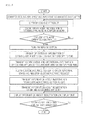
- Fig. 5 is a flowchart for explaining processes of receiving a customer's service request in the service system illustrated in Fig. 4 .
- Fig. 6 is a view illustrating another home appliance according to an embodiment.
- Fig. 7 is a view illustrating a service system for the home appliance illustrated in Fig. 6 .
- Fig. 8 is a flowchart for explaining processes of receiving a customer's service request in the service system illustrated in Fig. 7 .
- Fig. 9 is a view illustrating another home appliance according to an embodiment.
- Fig. 10 is a view illustrating a service system for the home appliance illustrated in Fig. 9 .
- Fig. 11 is a flowchart for explaining processes of receiving a customer's service request in the service system illustrated in Fig. 10 .
- Fig. 12 is a view illustrating another home appliance according to an embodiment.
- Fig. 13 is a view illustrating a service system for the home appliance illustrated in Fig. 12 .
- Fig. 14 is a flowchart for explaining processes of receiving a customer's service request in the service system illustrated in Fig. 13 .
- Fig. 1 is a schematic view illustrating the structure of a smart grid
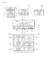
- Fig. 2 is a schematic view illustrating a configuration for supply power to home appliances according to an embodiment.
- the smart grid includes a plurality of power plants and a plurality of power generating facilities such as a solar cell station, a wind power plant, and a fuel cell station. Electricity generated by the power plants and power generating facilities are transmitted to a sub-control center.
- the sub-control center stores the electricity and transmits the electricity to a substation where the electricity is adjusted in voltage for being distributed to consumers such as residential customers and manufacturing plants.
- an advanced metering infrastructure (AMI) 20 is used to measure the amount of electricity consumed by consumers such as residential customers and offices and calculate electricity charges.
- an energy management system (EMS) 30 is connected to the AMI 20 for real-time power management and real-time power consumption prediction for consumers.
- the AMI 20 of the smart grid is backbone technology for integrating consumers based on an open architecture.
- the AMI 20 provides consumers with the ability to use electricity efficiently and power providers with the ability to detect problems on their systems and operate them efficiently.
- the AMI 20 provides a reference so that all electric devices can be connected to each other regardless of manufactures of the electric devices, and a real-time price signal of an electricity market is transmitted through the AMI 20 to the EMS 30 provided in a consumer.
- the EMS 30 distributes electricity to a plurality of electric devices provided in the consumer and communicates with the electric devices for detecting power information of the electric devices and performing a power information processing process such as a power consumption or electricity charge limit setting process so as to reduce energy consumption and costs.
- the EMS 30 includes a control unit 36 (refer to Fig. 4 ), an input unit 32, a communication unit 34 (refer to Fig. 4 ), and a display unit 31. These units will be described below in detail.
- the EMS 30 mainly supplies electricity to home appliances 1 provided in the consumer.
- an energy supply network 10 is constructed in the consumer.
- the energy supply network 10 includes the AMI 20 for real-time measurements of power, electricity rates, power consumption peak times; and the EMS 30 capable of communicating with both the AMI 20 and the home appliances 1 to transmit and receive control signals for distributing electricity to the home appliances 1.
- the EMS 30 includes: the display unit 31 for displaying current electricity consumption states and environments (such as temperature and humidity); the input unit 32 that can be manipulated by a user; the communication unit 34 for communication with the home appliances 1 through radio waves or wires such as PLC; and the control unit 36 for processing control signals.
- the display unit 31 for displaying current electricity consumption states and environments (such as temperature and humidity); the input unit 32 that can be manipulated by a user; the communication unit 34 for communication with the home appliances 1 through radio waves or wires such as PLC; and the control unit 36 for processing control signals.
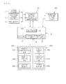
- a customer service center 800 is connected to the EMS 30 so that the home appliances 1 connected through wires in the consumer can be repaired if the home appliances 1 operate abnormally.
- a customer service system is constructed for home appliances according to an embodiment.
- the AMI 20, the EMS 30, and the customer service center 800 are connected to each other for two-way communication.
- the home appliances 1 are is connected to the EMS 30 through communication adaptors 600 (described later in detail with reference to Fig. 3 ) for two-way communication.
- operational information of the home appliances 1 can be transmitted to the customer service center 800 through the above-described communication path, and then the customer service center 800 checks the information and sends information about received customer requests to the home appliances 1 through the EMS 30.
- the customer service system for the home appliances 1 can be operated using the smart grid.
- Identification codes of the home appliances 1 connected to the EMS 30 are registered in the EMS 30, and when a customer service is requested, the identification code of a corresponding home appliance 1 is transmitted to the customer service center 800 together with operational information of the home appliance 1.
- EMSs 30 are provided in customers such as residential customers and offices, home codes for management may be assigned to the EMSs 30, respectively.
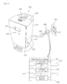
- Fig. 3 is a view illustrating a home appliance according to an embodiment
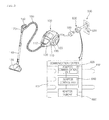
- Fig. 4 is a view illustrating a service system for the home appliance illustrated in Fig. 3
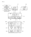
- Fig. 5 is a flowchart for explaining processes of receiving a customer's service request in the service system illustrated in Fig. 4 .
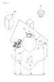
- a cleaner 100 is illustrated as an example of home the appliances 1.
- the cleaner 100 includes a nozzle 130 through which air containing dust is drawn; a handle 150 with which a user can handle the cleaner 100; an extension pipe 140 connecting the nozzle 130 to the handle 150; and a connection hose 160 connecting the nozzle 130 and a main body 110 of the cleaner 100 for guiding air and dust to the main body 110.
- the main body 110 includes a suction part 112 for suctioning air together with dust, and the connection hose 160 is coupled to the suction part 112.
- a dust collector 130 may be detachably disposed in the main body 110 for collecting dust and other substances from air sucked through the suction part 112 and storing the dust and the other substances, and wheels 120 may be provided on left and right sides of the main body 110 so that a user can easily carry out a cleaning operation while moving the main body 110 by holding the handle 150.
- a communication adapter 600 is connected to a plug 180 of the main body 110 of the cleaner 100 so that power supply to the main body 110 and two-way communication between the cleaner 100 and the EMS 30 can be possible.
- the communication adapter 600 is connected between the plug 180 and a socket 520 of an outlet 500 connected to the energy supply network 10 to allow power supply and two-way communication.
- the communication adapter 600 includes: a first coupling part 611 corresponding to the plug 180 for fitting the plug 180 in the first coupling part 611; and a second coupling part 612 corresponding to the socket 520 so as to be fitted into the socket 520.
- the cleaner 100 can be connected to the energy supply network 10 through the communication adapter 600.
- the communication adapter 600 includes: an adapter memory 660 for storing operational information of the cleaner 100; an adapter communication unit 620 communicating with the communication unit 34 of the EMS 30 and the cleaner 100 for transmitting and receiving the operational information; and an adapter control unit 640.
- the plug 180 of the cleaner 100 may include a data terminal in addition to a power terminal, and the first coupling part 611 may have a shape corresponding to the shape of the data terminal.
- a power management communication chip may be included in the cleaner 100 for transmitting and receiving operational information and power information to and from the adapter communication unit 620 and the communication unit 34 of the EMS 30.
- the cleaner 100 and the energy supply network 10 are connected through the communication adapter 600 as described above and the cleaner 100 is started, information such as the RPM and power consumption of a suction motor of the cleaner 100 is checked and stored in the adapter memory 660.
- an encoder may be further included in the main body 110 for detecting the RPM of the suction motor, and values measured by the encoder may be stored in the adapter memory 660.
- the main body 110 further includes a service button 190 for transmitting operational information stored in the adapter memory 660 to a cleaner customer service center 810 through the EMS 30.
- the service button 190 may be provided on a side of the main body 110 instead of being provided on the handle 150.
- a display unit is provided on the handle 150 for displaying reception information transmitted from the cleaner customer service center 810 in response to a customer service request transmitted by pressing the service button 190.
- the display unit may include a display 170 configured by a liquid crystal panel capable of displaying characters, and may display information such as an estimated defective part, an estimated repair cost, an estimated repair time, and the closest service center location.
- a display 170 configured by a liquid crystal panel capable of displaying characters, and may display information such as an estimated defective part, an estimated repair cost, an estimated repair time, and the closest service center location.
- the cleaner 100 may be operated as follows: the communication adapter 600 is coupled to the plug 180; and the communication adapter 600 is inserted into the outlet 500 connected to the energy supply network 10 provided in a residential customer so as to connect the cleaner 100 to the EMS 30.
- the EMS 30 selects one of power supply sources according to energy supply mode, and then power is distributed to the cleaner 100 from the selected power source under the control of the EMS 30.
- a user can clean a desired place while handling the cleaner 100 with the handle 150, and during cleaning after the EMS 30 and the cleaner 100 are connected, information about operations of the cleaner 100 is stored in the adapter memory 660.
- the user can press the service button 190 provided on the main body 110 to send a service request for the cleaner 100 to the cleaner customer service center 810.
- the EMS 30 transmits the information to the cleaner customer service center 810 together with the identification code of the cleaner 100 so that the cleaner customer service center 810 can check the information and the identification code for determining whether the cleaner 100 operates abnormally.
- the cleaner customer service center 810 In response to the customer service request, the cleaner customer service center 810 checks the home code of the EMS 30, the identification code of the cleaner 100, and the operational information of the cleaner 100 and registers the customer service request. Then, the cleaner customer service center 810 sends information about reception of the customer service request to the EMS 30.
- the reception information transmitted from the cleaner customer service center 810 to the EMS 30 may include information such as an estimated defective part, an estimated repair cost, an estimated repair time, and the closest service center location.
- the EMS 30 After receiving the reception information, the EMS 30 transmits the reception information to the cleaner 100 through the communication adapter 600, and the reception information is displayed on the display 170 of the cleaner 100. Thus, a user can be easily informed and receive a service.
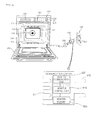
- Fig. 6 is a view illustrating another home appliance according to an embodiment
- Fig. 7 is a view illustrating a service system for the home appliance illustrated in Fig. 6
- Fig. 8 is a flowchart for explaining processes of receiving a customer's service request in the service system illustrated in Fig. 7 .
- a cooking appliance 200 is illustrated according to an embodiment.
- the cooking appliance 200 includes an outer case 201 forming the exterior of the cooking appliance 200, a cavity 210 formed in the outer case 201 to define a cooling chamber 212, a door 202 for opening and closing the cavity 210, a plurality of heating devices for heating a food disposed in the cooling chamber 212, and a control panel 230 provided on a side of the outer case 201 so that a user can manipulate the control panel 230.
- the cooking appliance 200 further includes a temperature detecting unit (not shown) for detecting the inside temperature of the cavity 210, a cooker control unit 236 for controlling the overall operation of the cooking appliance 200, and a cooker memory unit (not shown) for storing operational conditions of the cooking appliance 200.
- the cooker control unit 236 may generate a control signal for selecting one of the heating devices and time according to the kind of food disposed in the cooling chamber 212, or a user may manipulate the control panel 230 to select a control signal to be generated.
- the cooling chamber 212 may include an upper heater 240, a lower heater 250, and a convection device 220 as heating devices.
- the cooling chamber 212 may further include a magnetron or an ultrasonic device as a heating device.
- the control panel 230 includes: a manipulation unit 231 through which operational conditions of a heating device can be input; and a display unit 235 for displaying operational states of the cooking appliance 200.
- the manipulation unit 231 includes: a mode selection button 232 for selecting a heating device operation mode for cooking a food in the cooling chamber 212; a start button 233 for starting in the selected operation mode; and a service button 290 that can be pressed when the cooking appliance 200 operates abnormally so as to send a service request to a cooker customer service center 820.
- the display unit 235 may display operational states of the cooking appliance 200 controlled through the manipulation unit 231 and information about a customer service request transmitted to the cooker customer service center 820 through the service button 290.
- a communication adapter 600 may be connected to a plug 280 of the cooking appliance 200 so that power supply to the cooking appliance 200 and two-way communication between the cooking appliance 200 and the EMS 30 can be possible.
- the communication adapter 600 is connected between the plug 280 and a socket 520 of an outlet 500 connected to the energy supply network 10 to allow power supply and two-way communication.
- the communication adapter 600 includes: a first coupling part 611 corresponding to the plug 280 for fitting the plug 280 in the first coupling part 611; and a second coupling part 612 corresponding to the socket 520 so as to be fitted into the socket 520.
- the cooking appliance 200 can be connected to the energy supply network 10 through the communication adapter 600.
- the communication adapter 600 includes: an adapter memory 660 for storing operational information of the cooking appliance 200; an adapter communication unit 620 communicating with the communication unit 34 of the EMS 30 and the cooking appliance 200 for transmitting and receiving the operational information; and an adapter control unit 640.
- the plug 280 of the cooking appliance 200 may include a data terminal in addition to a power terminal, and the first coupling part 611 may have a shape corresponding to the shape of the data terminal.
- a power management communication chip may be included in the cooking appliance 200 for transmitting and receiving operational information and power information to and from the adapter communication unit 620 and the communication unit 34 of the EMS 30.
- the cooking appliance 200 and the energy supply network 10 are connected through the communication adapter 600 as described above and the cooking appliance 200 is operated, operational information such as heating device operational states and power consumption rates is checked and stored in the adapter memory 660.
- the adapter control unit 640 transmits the operational information of the cooking appliance 200 stored in the adapter memory 660 to the EMS 30 through the adapter communication unit 620.
- the EMS 30 After receiving the operational information, the EMS 30 transmits the operational information to the cooker customer service center 820 together with the identification code of the cooking appliance 200 so that a cooker service request can be applied.
- a user may cook a food using the cooking appliance 200 as follows.
- the communication adapter 600 is coupled to the plug 280; and the communication adapter 600 is inserted into the outlet 500 connected to the energy supply network 10 provided in a residential customer so as to connect the cooking appliance 200 to the EMS 30.
- the EMS 30 selects one of power supply sources according to energy supply mode, and then power is distributed to the cooking appliance 200 from the selected power source under the control of the EMS 30.
- a user selects a cooling mode through the manipulation unit 231 of the cooking appliance 200 and presses a manipulation button to operate the cooking appliance 200 in the selected cooling mode.
- a manipulation button to operate the cooking appliance 200 in the selected cooling mode.
- one or more of the heating devices of the cooking appliance 200 are operated according to the selected cooking mode so that the food can be cooked while storing operational information of the cooking appliance 200 in the adapter memory 660.
- a user can press the service button 290 provided on a side of the manipulation unit 231 to send a customer service request to the cooker customer service center 820.
- the communication adapter 600 sends the operational information of the cooking appliance 200 stored in the adapter memory 660 to the EMS 30.
- the EMS 30 sends the operational information of the cooking appliance 200 to the cooker customer service center 820 together with the identification code of the cooking appliance 200 so that the cooker customer service center 820 can check the information and determine whether the cooking appliance 200 operates abnormally.
- the cooker customer service center 820 In response to the customer service request, the cooker customer service center 820 checks the home code of the EMS 30, the identification code of the cooking appliance 200, and the operational information of the cooking appliance 200, and registers the customer service request. Then, the cooker customer service center 820 sends information about reception of the customer service request to the EMS 30.
- the reception information transmitted from the cooker customer service center 820 to the EMS 30 may include information such as an estimated defective part, an estimated repair cost, an estimated repair time, and the closest service center location.
- the EMS 30 After receiving the reception information, the EMS 30 transmits the reception information to the cooking appliance 200 through the communication adapter 600, and the reception information is displayed on the display unit 235 of the cooking appliance 200.
- the EMS 30 After receiving the reception information, the EMS 30 transmits the reception information to the cooking appliance 200 through the communication adapter 600, and the reception information is displayed on the display unit 235 of the cooking appliance 200.
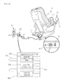
- Fig. 9 is a view illustrating another home appliance according to an embodiment
- Fig. 10 is a view illustrating a service system for the home appliance illustrated in Fig. 9
- Fig. 11 is a flowchart for explaining processes of receiving a customer's service request in the service system illustrated in Fig. 10 .
- a humidifier 300 is illustrated according to an embodiment.
- the humidifier 300 includes a humidifier main body 310 and a water tank 320 disposed on the humidifier main body 310 to supply water.
- the humidifier main body 310 and the water tank 320 form the exterior of the humidifier 300.
- the humidifier main body 310 includes a tub part (not shown) for containing water supplied from the water tank 320.
- the tub part includes: a water level sensor for detecting the water level in the water tank 320; and a vibrator or a heating unit such as a heater or an electrode rod for producing wet steam from water supplied from the water tank 320.
- Wet steam produced by the vibrator or the heating unit may be discharged to the outside through a wet steam outlet of the water tank 320, and the humidifier main body 310 may include a blower for facilitating discharging of the wet steam.
- a spray guide 330 may be disposed on the water tank 320 to guide wet steam discharging from the water tank 320, and a water tank handle 340 is provided on a side of the water tank 320 so that a user can easily attach and detach the water tank 320 by holding the water tank handle 340.
- the water tank 320 is disposed on the rear side of the humidifier main body 310 and forms the rear exterior of the humidifier 300.
- a front display unit 360 is provided the front side of the humidifier main body 310 so that a user can check the operational state of the humidifier 300.
- the front display unit 360 includes a liquid crystal panel capable of display letters and numerals.
- the front display unit 360 may display information about a customer service request sent by pressing a service button 390 (described later).
- the service button 390 may be provided on a rear lateral side of the humidifier main body 390 at a position spaced apart from an adjustor 350, and if necessary, a user can press the service button 390.
- the adjustor 350 is provided at a side of the front display unit 360 to receive a control command for operating the humidifier 300.
- a humidifier control unit 316 generates a control command for operating the vibrator or the heating unit and the blower corresponding to the control condition. In this way, indoor humidity can be controlled using the humidifier 300.
- a communication adapter 600 may be connected to a plug 380 of the humidifier 300 so that power supply to the humidifier 300 and two-way communication between the humidifier 300 and the EMS 30 can be possible.
- the communication adapter 600 is connected between the plug 380 and a socket 520 of an outlet 500 connected to the energy supply network 10 to allow power supply and two-way communication.
- the communication adapter 600 includes: a first coupling part 611 corresponding to the plug 380 for fitting the plug 380 in the first coupling part 611; and a second coupling part 612 corresponding to the socket 520 so as to be fitted into the socket 520.
- the humidifier 300 can be connected to the energy supply network 10 through the communication adapter 600.
- the communication adapter 600 includes: an adapter memory 660 for storing operational information of the humidifier 300; an adapter communication unit 620 communicating with the communication unit 34 of the EMS 30 and the humidifier 300 for transmitting and receiving the operational information; and an adapter control unit 640.
- the plug 380 of the humidifier 300 may include a data terminal in addition to a power terminal, and the first coupling part 611 may have a shape corresponding to the shape of the data terminal.
- a power management communication chip may be included in the humidifier 300 for transmitting and receiving operational information and power information to and from the adapter communication unit 620 and the communication unit 34 of the EMS 30.
- the humidifier 300 and the energy supply network 10 are connected through the communication adapter 600 as described above and a control signal is input through the adjustor 350, information such as operational states and power consumption rates of the vibrator or the heating unit is checked and stored in the adapter memory 660.
- the adapter control unit 640 transmits operational information of the humidifier 300 stored in the adapter memory 660 to the EMS 30 through the adapter communication unit 620.
- the EMS 30 After receiving the operational information, the EMS 30 transmits the operational information to a humidifier customer service center 830 together with the identification code of the humidifier 300 so that a humidifier service request can be applied.
- a user may improve indoor environments by using the humidifier 300 as follows.
- the communication adapter 600 is coupled to the plug 380; and the communication adapter 600 is inserted into the outlet 500 connected to the energy supply network 10 provided in a residential customer so as to connect the humidifier 300 to the EMS 30.
- the EMS 30 selects one of power supply sources according to energy supply mode, and then power is distributed to the humidifier 300 from the selected power source under the control of the EMS 30.
- a user sets conditions such as a spraying rate and time of wet steam using the adjustor 350 of the humidifier 300 for adjusting the humidity of an indoor area.
- the vibrator or the heating unit is operated to generate and spray wet steam according to an input control signal, and operational information of the humidifier 300 is stored in the adapter memory 660.
- a user may press the service button 390 to send a customer service request to the humidifier customer service center 830.
- the communication adapter 600 sends the operational information of the humidifier 300 stored in the adapter memory 660 to the EMS 30.
- the EMS 30 sends the operational information of the humidifier 300 to the humidifier customer service center 830 together with the identification code of the humidifier 300 so that the humidifier customer service center 830 can check the information and determine whether the humidifier 300 operates abnormally.
- the humidifier customer service center 830 In response to the customer service request, the humidifier customer service center 830 checks the home code of the EMS 30, the identification code of the humidifier 300, and the operational information of the humidifier 300, and registers the customer service request. Then, the humidifier customer service center 830 sends information about reception of the customer service request to the EMS 30.
- the reception information transmitted from the humidifier customer service center 830 to the EMS 30 may include information such as an estimated defective part, an estimated repair cost, an estimated repair time, and the closest service center location.
- the EMS 30 After receiving the reception information, the EMS 30 transmits the reception information to the humidifier 300 through the communication adapter 600, and the reception information is displayed on the front display unit 360 of the humidifier 300.
- the EMS 30 After receiving the reception information, the EMS 30 transmits the reception information to the humidifier 300 through the communication adapter 600, and the reception information is displayed on the front display unit 360 of the humidifier 300.
- Fig. 12 is a view illustrating another home appliance according to an embodiment
- Fig. 13 is a view illustrating a service system for the home appliance illustrated in Fig. 12
- Fig. 14 is a flowchart for explaining processes of receiving a customer's service request in the service system illustrated in Fig. 13 .
- a massage chair 400 is illustrated according to an embodiment.
- the massage chair 400 is used to massage the body of a user.
- the body of a user can be massaged wholly or partially by using the massage chair 400, and for this, the massage chair 400 includes a plurality of motors and an air adjusting device connected to a plurality of air bags.
- the massage chair 400 includes a back massage unit 420, an arm massage unit 440, leg and foot massage units (not shown).
- the massage units of the massage chair 400 may be individually controlled by the motors and the air adjusting device for massage parts of a user's body independently.
- the back massage unit 420 and the feet massage unit include a plurality of protrusions connected to the motors for being moved in various manners for massaging the back and feet of a user sit on the massage chair 400.
- the arm massage unit 440 and the leg massage unit include air bags that can be expanded and contracted by the air adjusting device for massaging the arms and legs of a user.
- the massage chair 400 includes a remote controller 460 and a massage chair control unit 410.
- the massage units of the massage chair 400 can be used selectively or simultaneously by using the remote controller 460, and the massage chair control unit 410 sends control commands to the massage units according to selection through the remote controller 460.
- the remote controller 460 is disposed on a side of the arm massage unit 440 so that a user sit on the massage chair 400 can easily see the remote controller 460, and the remote controller 460 includes a touch display 462 so that a user can easily check and select an operation mode.
- the massage chair control unit 410 includes a plug 480, and the plug 480 can be connected to the EMS 30 using a communication adapter 600 for receiving power while communicating with the EMS 30.
- the massage chair control unit 410 includes a service button 490 so that if the massage chair 400 operates abnormally, a user can press the service button 490 to send a customer service request to a massage chair customer service center 840 through the EMS 30.
- a power button 412 may be provided at a side of the service button 490 for turning the massage chair 400 on and off.
- a button having the same function as the service button 490 may be provided on the touch display 462 of the remote controller 460. However, in the current embodiment, only the service button 490 is provided at a side of the massage chair control unit 410 to prevent a service request caused by a mistake. If necessary, a user can send a service request using the service button 490.
- the communication adapter 600 connects the plug 480 to a socket 520 of an outlet 500 connected to the energy supply network 10 so that power supply and two-way communication can be possible.
- the communication adapter 600 includes: a first coupling part 611 corresponding to the plug 480 for fitting the plug 480 in the first coupling part 611; and a second coupling part 612 corresponding to the socket 520 so as to be fitted into the socket 520.
- the massage chair 400 can be connected to the energy supply network 10 through the communication adapter 600.
- the communication adapter 600 includes: an adapter memory 660 for storing operational information of the massage chair 400; an adapter communication unit 620 communicating with the communication unit 34 of the EMS 30 and the massage chair 400 for transmitting and receiving the operational information; and an adapter control unit 640.
- the plug 480 of the massage chair 400 may include a data terminal in addition to a power terminal, and the first coupling part 611 may have a shape corresponding to the shape of the data terminal.
- a power management communication chip may be included in the humidifier 300 for transmitting and receiving operational information and power information to and from the adapter communication unit 620 and the communication unit 34 of the EMS 30.
- the massage chair 400 and the energy supply network 10 are connected through the communication adapter 600 as described above and a control signal is input through the remote controller 460, operational information such as operation states and power consumption rates of the motors and/or the air adjusting device is input through the remote controller 460 is checked and stored in the adapter memory 660.
- the adapter control unit 640 transmits the operational information of the massage chair 400 stored in the adapter memory 660 to the EMS 30 through the adapter communication unit 620.
- the EMS 30 After receiving the operational information, the EMS 30 transmits the operational information to the massage chair customer service center 840 together with the identification code of the massage chair 400 so that a massage chair service request can be applied.
- a user may massage a part or all parts of his body by using the massage chair 400 as follows.
- the communication adapter 600 is coupled to the plug 480; and the communication adapter 600 is inserted into the outlet 500 connected to the energy supply network 10 provided in a residential customer so as to connect the massage chair 400 to the EMS 30.
- the EMS 30 selects one of power supply sources according to energy supply mode, and then power is distributed to the massage chair 400 from the selected power source under the control of the EMS 30.
- a user can set conditions such as a part to be massaged and a massage time using the remote controller 460, and enjoy massage according to the set conditions.
- a user may press the service button 490 to send a customer service request to the humidifier chair customer service center 840.
- the communication adapter 600 sends the operational information of the massage chair 400 stored in the adapter memory 660 to the EMS 30.
- the EMS 30 sends the operational information of the massage chair 400 to the massage chair customer service center 840 together with the identification code of the massage chair 400 so that the massage chair customer service center 840 can check the information and determine whether the massage chair 400 operates abnormally.
- the massage chair customer service center 840 checks the home code of the EMS 30, the identification code of the humidifier 300, and the operational information of the humidifier 300, and registers the customer service request. Then, the massage chair customer service center 840 sends information about reception of the customer service request to the EMS 30.
- the reception information transmitted from the massage chair customer service center 840 to the EMS 30 may include information such as an estimated defective part, an estimated repair cost, an estimated repair time, and the closest service center location.
- the EMS 30 After receiving the reception information, the EMS 30 transmits the reception information to the massage chair 400 through the communication adapter 600, and the reception information is displayed on the touch display 462 of the massage chair 400.
- the EMS 30 After receiving the reception information, the EMS 30 transmits the reception information to the massage chair 400 through the communication adapter 600, and the reception information is displayed on the touch display 462 of the massage chair 400.
Landscapes
- Engineering & Computer Science (AREA)
- Power Engineering (AREA)
- Computer Networks & Wireless Communication (AREA)
- Signal Processing (AREA)
- Physics & Mathematics (AREA)
- General Physics & Mathematics (AREA)
- Selective Calling Equipment (AREA)
- Telephonic Communication Services (AREA)
Applications Claiming Priority (1)
| Application Number | Priority Date | Filing Date | Title |
|---|---|---|---|
| PCT/KR2010/000229 WO2011087164A1 (ko) | 2010-01-14 | 2010-01-14 | 지능형 전력망을 이용한 가전제품의 고객서비스 시스템 |
Publications (3)
| Publication Number | Publication Date |
|---|---|
| EP2525307A1 true EP2525307A1 (de) | 2012-11-21 |
| EP2525307A4 EP2525307A4 (de) | 2017-03-15 |
| EP2525307B1 EP2525307B1 (de) | 2018-01-03 |
Family
ID=44304422
Family Applications (1)
| Application Number | Title | Priority Date | Filing Date |
|---|---|---|---|
| EP10843230.3A Active EP2525307B1 (de) | 2010-01-14 | 2010-01-14 | Kundendienstsystem für hausgeräte mit intelligentem stromnetz |
Country Status (3)
| Country | Link |
|---|---|
| US (1) | US20130024385A1 (de) |
| EP (1) | EP2525307B1 (de) |
| WO (1) | WO2011087164A1 (de) |
Cited By (2)
| Publication number | Priority date | Publication date | Assignee | Title |
|---|---|---|---|---|
| WO2014116415A1 (en) * | 2013-01-25 | 2014-07-31 | Tyco Electronics Corporation | Communication module adaptor |
| CN104408660A (zh) * | 2014-11-11 | 2015-03-11 | 江苏联海通信技术有限公司 | 一种自助式ktv控制系统及方法 |
Families Citing this family (9)
| Publication number | Priority date | Publication date | Assignee | Title |
|---|---|---|---|---|
| US20120239581A1 (en) * | 2011-03-14 | 2012-09-20 | Mosher Doyle W | Scalable method and system for connecting, tracking and facilitating warranty, maintenance, service and replacement of products within a community of residential housing and/or commercial building inventories or units over a communications network |
| US8649883B2 (en) | 2011-10-04 | 2014-02-11 | Advanergy, Inc. | Power distribution system and method |
| WO2013052671A2 (en) * | 2011-10-04 | 2013-04-11 | Advanergy, Inc. | Power control system and method |
| KR20130090978A (ko) * | 2012-02-07 | 2013-08-16 | 삼성전자주식회사 | 전력선 통신 장치 및 방법, 이를 이용한 부하 전력 모니터링 장치 및 방법 |
| KR101708992B1 (ko) | 2015-03-16 | 2017-02-21 | 엘지전자 주식회사 | 가전기기 진단시스템 및 그 진단방법 |
| KR102415871B1 (ko) * | 2016-01-08 | 2022-07-04 | 삼성전자주식회사 | 디스플레이 장치 및 그 동작방법 |
| US10396557B2 (en) | 2017-10-19 | 2019-08-27 | Whirlpool Corporation | Domestic appliance demand-response power consumption control system and method |
| US11206308B2 (en) | 2019-04-26 | 2021-12-21 | At&T Intellectual Property I, L.P. | Facilitating support functionalities through a support appliance device in advanced networks |
| US12261714B2 (en) * | 2022-04-06 | 2025-03-25 | Haier Us Appliance Solutions, Inc. | Service mode indication for domestic appliances |
Family Cites Families (23)
| Publication number | Priority date | Publication date | Assignee | Title |
|---|---|---|---|---|
| US6473788B1 (en) * | 1996-11-15 | 2002-10-29 | Canon Kabushiki Kaisha | Remote maintenance and servicing of a network peripheral device over the world wide web |
| US6003078A (en) * | 1996-11-15 | 1999-12-14 | Canon Information Systems, Inc. | Automatic service requests over the world wide web |
| JP2000048066A (ja) * | 1998-07-27 | 2000-02-18 | Hitachi Ltd | ライフサイクル管理方法、システム、および製品 |
| US20020011923A1 (en) * | 2000-01-13 | 2002-01-31 | Thalia Products, Inc. | Appliance Communication And Control System And Appliance For Use In Same |
| KR100657114B1 (ko) * | 2000-08-10 | 2006-12-12 | 엘지전자 주식회사 | 홈네트워크를 이용한 애프터서비스 방법 |
| US6937999B1 (en) * | 2000-11-10 | 2005-08-30 | Hewlett-Packard Development Company L.P. | Reorder-assistance functionality levels |
| JP4149178B2 (ja) * | 2001-03-09 | 2008-09-10 | 松下電器産業株式会社 | リモートメンテナンスシステム |
| JP4238483B2 (ja) * | 2001-03-12 | 2009-03-18 | 株式会社日立製作所 | 電化製品賃貸システム |
| US7031933B2 (en) * | 2001-03-29 | 2006-04-18 | Hewlett-Packard Development Company, L.P. | Process for setting and storing ordering preferences and profile data locally |
| US7290247B2 (en) * | 2001-10-25 | 2007-10-30 | Aol, Llc, A Delaware Limited Liability Company | Help center and filtering applications |
| US6759946B2 (en) * | 2001-12-06 | 2004-07-06 | Mitsubishi Electric Research Laboratories, Inc. | Home appliances network |
| US7124097B2 (en) * | 2002-01-23 | 2006-10-17 | Xerox Corporation | Method and system for ordering a consumable for a device |
| KR100436090B1 (ko) * | 2002-03-18 | 2004-06-23 | 김미현 | 수도 가스의 검침, 방재와 보안정보를 처리하는 에스아이유를 내장한 전력량계 |
| KR20040017695A (ko) * | 2002-08-23 | 2004-02-27 | 삼성전자주식회사 | 가전기기용 전력선 통신 시스템 및 방법 |
| KR101058001B1 (ko) * | 2004-01-02 | 2011-08-19 | 삼성전자주식회사 | 네트워크 기기에 대한 애프터 서비스 제공 방법 및 그시스템 |
| KR100632924B1 (ko) * | 2004-06-10 | 2006-10-12 | 주식회사 젤라인 | 전력선 통신 장치 및 방법 |
| US20060184377A1 (en) * | 2005-02-14 | 2006-08-17 | Accenture Global Services Gmbh | Embedded warranty management |
| US20090187413A1 (en) * | 2008-01-18 | 2009-07-23 | Timothy Abels | Service delivery platform for automated and remote information technology management |
| WO2010025307A1 (en) * | 2008-08-27 | 2010-03-04 | Convia, Inc. | Energy distribution management system |
| US20100211509A1 (en) * | 2009-02-17 | 2010-08-19 | Jacobs Richard B | Resource monitoring device |
| US8984338B2 (en) * | 2009-07-06 | 2015-03-17 | Lg Electronics Inc. | Home appliance diagnosis system, and method for operating same |
| US20110202293A1 (en) * | 2010-02-15 | 2011-08-18 | General Electric Company | Diagnostics using sub-metering device |
| US9361637B2 (en) * | 2010-03-05 | 2016-06-07 | Sears Brands, L.L.C. | System and method for providing diagnostic services |
-
2010
- 2010-01-14 WO PCT/KR2010/000229 patent/WO2011087164A1/ko not_active Ceased
- 2010-01-14 US US13/522,229 patent/US20130024385A1/en not_active Abandoned
- 2010-01-14 EP EP10843230.3A patent/EP2525307B1/de active Active
Cited By (4)
| Publication number | Priority date | Publication date | Assignee | Title |
|---|---|---|---|---|
| WO2014116415A1 (en) * | 2013-01-25 | 2014-07-31 | Tyco Electronics Corporation | Communication module adaptor |
| CN104995802A (zh) * | 2013-01-25 | 2015-10-21 | 泰科电子公司 | 通信模块适配器 |
| US9343861B2 (en) | 2013-01-25 | 2016-05-17 | Tyco Electronics Corporation | Communication module adaptor |
| CN104408660A (zh) * | 2014-11-11 | 2015-03-11 | 江苏联海通信技术有限公司 | 一种自助式ktv控制系统及方法 |
Also Published As
| Publication number | Publication date |
|---|---|
| EP2525307A4 (de) | 2017-03-15 |
| US20130024385A1 (en) | 2013-01-24 |
| WO2011087164A1 (ko) | 2011-07-21 |
| EP2525307B1 (de) | 2018-01-03 |
Similar Documents
| Publication | Publication Date | Title |
|---|---|---|
| EP2525307B1 (de) | Kundendienstsystem für hausgeräte mit intelligentem stromnetz | |
| US9337658B2 (en) | Network system | |
| EP2525471B1 (de) | Notstromversorgungsvorrichtung für haushaltsgeräte mit intelligentem stromnetz | |
| JP6054945B2 (ja) | ダクトなし分離型システム用のはん用需要応答型リモコン | |
| US9797934B2 (en) | Home appliance having built-in power meter | |
| US8798834B2 (en) | Movable component for a network system | |
| US9386905B2 (en) | Network system | |
| US20130192020A1 (en) | Vacuum cleaner using smart grid | |
| US8978195B2 (en) | Vacuum cleaner using an intelligent power network | |
| KR101069058B1 (ko) | 지능형 전력망을 이용하는 정수기 | |
| KR101101657B1 (ko) | 지능형 전력망을 이용하는 가전제품의 보조전원공급장치 | |
| KR101166624B1 (ko) | 지능형 전력망을 이용하는 가전제품 | |
| KR101158615B1 (ko) | 지능형 전력망을 이용하는 가전제품 | |
| US20130018520A1 (en) | Execution method of one function of a plurality of functions at a component | |
| KR101101522B1 (ko) | 지능형 전력망을 이용하는 조리기 | |
| JP7502918B2 (ja) | 電力自給自足率算出装置 | |
| WO2011106355A1 (en) | An execution method of one function of a plurality of functions at a component | |
| KR101134183B1 (ko) | 지능형 전력망을 이용하는 진공청소기 | |
| KR101101547B1 (ko) | 조리기의 제어방법 | |
| KR101136604B1 (ko) | 지능형 전력망을 이용하는 진공청소기 | |
| KR20110101539A (ko) | 지능형 전력망을 이용한 가전제품의 고객서비스 시스템 | |
| CN103777065A (zh) | 一种新型无线传输的电流测量装置 |
Legal Events
| Date | Code | Title | Description |
|---|---|---|---|
| PUAI | Public reference made under article 153(3) epc to a published international application that has entered the european phase |
Free format text: ORIGINAL CODE: 0009012 |
|
| 17P | Request for examination filed |
Effective date: 20120731 |
|
| AK | Designated contracting states |
Kind code of ref document: A1 Designated state(s): AT BE BG CH CY CZ DE DK EE ES FI FR GB GR HR HU IE IS IT LI LT LU LV MC MK MT NL NO PL PT RO SE SI SK SM TR |
|
| DAX | Request for extension of the european patent (deleted) | ||
| RIC1 | Information provided on ipc code assigned before grant |
Ipc: G06Q 10/00 20120101AFI20161027BHEP Ipc: G06Q 50/00 20120101ALI20161027BHEP |
|
| RA4 | Supplementary search report drawn up and despatched (corrected) |
Effective date: 20170209 |
|
| RIC1 | Information provided on ipc code assigned before grant |
Ipc: G06Q 50/00 20120101ALI20170203BHEP Ipc: G06Q 10/00 20120101AFI20170203BHEP |
|
| GRAP | Despatch of communication of intention to grant a patent |
Free format text: ORIGINAL CODE: EPIDOSNIGR1 |
|
| INTG | Intention to grant announced |
Effective date: 20170718 |
|
| GRAS | Grant fee paid |
Free format text: ORIGINAL CODE: EPIDOSNIGR3 |
|
| GRAA | (expected) grant |
Free format text: ORIGINAL CODE: 0009210 |
|
| AK | Designated contracting states |
Kind code of ref document: B1 Designated state(s): AT BE BG CH CY CZ DE DK EE ES FI FR GB GR HR HU IE IS IT LI LT LU LV MC MK MT NL NO PL PT RO SE SI SK SM TR |
|
| REG | Reference to a national code |
Ref country code: GB Ref legal event code: FG4D |
|
| REG | Reference to a national code |
Ref country code: AT Ref legal event code: REF Ref document number: 960927 Country of ref document: AT Kind code of ref document: T Effective date: 20180115 Ref country code: CH Ref legal event code: EP |
|
| REG | Reference to a national code |
Ref country code: FR Ref legal event code: PLFP Year of fee payment: 9 |
|
| REG | Reference to a national code |
Ref country code: IE Ref legal event code: FG4D |
|
| REG | Reference to a national code |
Ref country code: DE Ref legal event code: R096 Ref document number: 602010047860 Country of ref document: DE |
|
| REG | Reference to a national code |
Ref country code: NL Ref legal event code: MP Effective date: 20180103 |
|
| REG | Reference to a national code |
Ref country code: LT Ref legal event code: MG4D |
|
| REG | Reference to a national code |
Ref country code: AT Ref legal event code: MK05 Ref document number: 960927 Country of ref document: AT Kind code of ref document: T Effective date: 20180103 |
|
| PG25 | Lapsed in a contracting state [announced via postgrant information from national office to epo] |
Ref country code: NL Free format text: LAPSE BECAUSE OF FAILURE TO SUBMIT A TRANSLATION OF THE DESCRIPTION OR TO PAY THE FEE WITHIN THE PRESCRIBED TIME-LIMIT Effective date: 20180103 |
|
| PG25 | Lapsed in a contracting state [announced via postgrant information from national office to epo] |
Ref country code: FI Free format text: LAPSE BECAUSE OF FAILURE TO SUBMIT A TRANSLATION OF THE DESCRIPTION OR TO PAY THE FEE WITHIN THE PRESCRIBED TIME-LIMIT Effective date: 20180103 Ref country code: LT Free format text: LAPSE BECAUSE OF FAILURE TO SUBMIT A TRANSLATION OF THE DESCRIPTION OR TO PAY THE FEE WITHIN THE PRESCRIBED TIME-LIMIT Effective date: 20180103 Ref country code: ES Free format text: LAPSE BECAUSE OF FAILURE TO SUBMIT A TRANSLATION OF THE DESCRIPTION OR TO PAY THE FEE WITHIN THE PRESCRIBED TIME-LIMIT Effective date: 20180103 Ref country code: CY Free format text: LAPSE BECAUSE OF FAILURE TO SUBMIT A TRANSLATION OF THE DESCRIPTION OR TO PAY THE FEE WITHIN THE PRESCRIBED TIME-LIMIT Effective date: 20180103 Ref country code: NO Free format text: LAPSE BECAUSE OF FAILURE TO SUBMIT A TRANSLATION OF THE DESCRIPTION OR TO PAY THE FEE WITHIN THE PRESCRIBED TIME-LIMIT Effective date: 20180403 Ref country code: HR Free format text: LAPSE BECAUSE OF FAILURE TO SUBMIT A TRANSLATION OF THE DESCRIPTION OR TO PAY THE FEE WITHIN THE PRESCRIBED TIME-LIMIT Effective date: 20180103 |
|
| PG25 | Lapsed in a contracting state [announced via postgrant information from national office to epo] |
Ref country code: BG Free format text: LAPSE BECAUSE OF FAILURE TO SUBMIT A TRANSLATION OF THE DESCRIPTION OR TO PAY THE FEE WITHIN THE PRESCRIBED TIME-LIMIT Effective date: 20180403 Ref country code: IS Free format text: LAPSE BECAUSE OF FAILURE TO SUBMIT A TRANSLATION OF THE DESCRIPTION OR TO PAY THE FEE WITHIN THE PRESCRIBED TIME-LIMIT Effective date: 20180503 Ref country code: GR Free format text: LAPSE BECAUSE OF FAILURE TO SUBMIT A TRANSLATION OF THE DESCRIPTION OR TO PAY THE FEE WITHIN THE PRESCRIBED TIME-LIMIT Effective date: 20180404 Ref country code: LV Free format text: LAPSE BECAUSE OF FAILURE TO SUBMIT A TRANSLATION OF THE DESCRIPTION OR TO PAY THE FEE WITHIN THE PRESCRIBED TIME-LIMIT Effective date: 20180103 Ref country code: SE Free format text: LAPSE BECAUSE OF FAILURE TO SUBMIT A TRANSLATION OF THE DESCRIPTION OR TO PAY THE FEE WITHIN THE PRESCRIBED TIME-LIMIT Effective date: 20180103 Ref country code: AT Free format text: LAPSE BECAUSE OF FAILURE TO SUBMIT A TRANSLATION OF THE DESCRIPTION OR TO PAY THE FEE WITHIN THE PRESCRIBED TIME-LIMIT Effective date: 20180103 Ref country code: PL Free format text: LAPSE BECAUSE OF FAILURE TO SUBMIT A TRANSLATION OF THE DESCRIPTION OR TO PAY THE FEE WITHIN THE PRESCRIBED TIME-LIMIT Effective date: 20180103 |
|
| REG | Reference to a national code |
Ref country code: CH Ref legal event code: PL |
|
| REG | Reference to a national code |
Ref country code: DE Ref legal event code: R097 Ref document number: 602010047860 Country of ref document: DE |
|
| PG25 | Lapsed in a contracting state [announced via postgrant information from national office to epo] |
Ref country code: RO Free format text: LAPSE BECAUSE OF FAILURE TO SUBMIT A TRANSLATION OF THE DESCRIPTION OR TO PAY THE FEE WITHIN THE PRESCRIBED TIME-LIMIT Effective date: 20180103 Ref country code: EE Free format text: LAPSE BECAUSE OF FAILURE TO SUBMIT A TRANSLATION OF THE DESCRIPTION OR TO PAY THE FEE WITHIN THE PRESCRIBED TIME-LIMIT Effective date: 20180103 Ref country code: IT Free format text: LAPSE BECAUSE OF FAILURE TO SUBMIT A TRANSLATION OF THE DESCRIPTION OR TO PAY THE FEE WITHIN THE PRESCRIBED TIME-LIMIT Effective date: 20180103 Ref country code: MC Free format text: LAPSE BECAUSE OF FAILURE TO SUBMIT A TRANSLATION OF THE DESCRIPTION OR TO PAY THE FEE WITHIN THE PRESCRIBED TIME-LIMIT Effective date: 20180103 Ref country code: LU Free format text: LAPSE BECAUSE OF NON-PAYMENT OF DUE FEES Effective date: 20180114 |
|
| REG | Reference to a national code |
Ref country code: IE Ref legal event code: MM4A |
|
| REG | Reference to a national code |
Ref country code: BE Ref legal event code: MM Effective date: 20180131 |
|
| PLBE | No opposition filed within time limit |
Free format text: ORIGINAL CODE: 0009261 |
|
| STAA | Information on the status of an ep patent application or granted ep patent |
Free format text: STATUS: NO OPPOSITION FILED WITHIN TIME LIMIT |
|
| PG25 | Lapsed in a contracting state [announced via postgrant information from national office to epo] |
Ref country code: SK Free format text: LAPSE BECAUSE OF FAILURE TO SUBMIT A TRANSLATION OF THE DESCRIPTION OR TO PAY THE FEE WITHIN THE PRESCRIBED TIME-LIMIT Effective date: 20180103 Ref country code: DK Free format text: LAPSE BECAUSE OF FAILURE TO SUBMIT A TRANSLATION OF THE DESCRIPTION OR TO PAY THE FEE WITHIN THE PRESCRIBED TIME-LIMIT Effective date: 20180103 Ref country code: BE Free format text: LAPSE BECAUSE OF NON-PAYMENT OF DUE FEES Effective date: 20180131 Ref country code: CH Free format text: LAPSE BECAUSE OF NON-PAYMENT OF DUE FEES Effective date: 20180131 Ref country code: LI Free format text: LAPSE BECAUSE OF NON-PAYMENT OF DUE FEES Effective date: 20180131 Ref country code: CZ Free format text: LAPSE BECAUSE OF FAILURE TO SUBMIT A TRANSLATION OF THE DESCRIPTION OR TO PAY THE FEE WITHIN THE PRESCRIBED TIME-LIMIT Effective date: 20180103 Ref country code: SM Free format text: LAPSE BECAUSE OF FAILURE TO SUBMIT A TRANSLATION OF THE DESCRIPTION OR TO PAY THE FEE WITHIN THE PRESCRIBED TIME-LIMIT Effective date: 20180103 |
|
| 26N | No opposition filed |
Effective date: 20181005 |
|
| PG25 | Lapsed in a contracting state [announced via postgrant information from national office to epo] |
Ref country code: IE Free format text: LAPSE BECAUSE OF NON-PAYMENT OF DUE FEES Effective date: 20180114 |
|
| PG25 | Lapsed in a contracting state [announced via postgrant information from national office to epo] |
Ref country code: SI Free format text: LAPSE BECAUSE OF FAILURE TO SUBMIT A TRANSLATION OF THE DESCRIPTION OR TO PAY THE FEE WITHIN THE PRESCRIBED TIME-LIMIT Effective date: 20180103 |
|
| PG25 | Lapsed in a contracting state [announced via postgrant information from national office to epo] |
Ref country code: MT Free format text: LAPSE BECAUSE OF NON-PAYMENT OF DUE FEES Effective date: 20180114 |
|
| PGFP | Annual fee paid to national office [announced via postgrant information from national office to epo] |
Ref country code: FR Payment date: 20191209 Year of fee payment: 11 |
|
| PG25 | Lapsed in a contracting state [announced via postgrant information from national office to epo] |
Ref country code: TR Free format text: LAPSE BECAUSE OF FAILURE TO SUBMIT A TRANSLATION OF THE DESCRIPTION OR TO PAY THE FEE WITHIN THE PRESCRIBED TIME-LIMIT Effective date: 20180103 |
|
| PGFP | Annual fee paid to national office [announced via postgrant information from national office to epo] |
Ref country code: GB Payment date: 20191209 Year of fee payment: 11 |
|
| PG25 | Lapsed in a contracting state [announced via postgrant information from national office to epo] |
Ref country code: PT Free format text: LAPSE BECAUSE OF FAILURE TO SUBMIT A TRANSLATION OF THE DESCRIPTION OR TO PAY THE FEE WITHIN THE PRESCRIBED TIME-LIMIT Effective date: 20180103 Ref country code: HU Free format text: LAPSE BECAUSE OF FAILURE TO SUBMIT A TRANSLATION OF THE DESCRIPTION OR TO PAY THE FEE WITHIN THE PRESCRIBED TIME-LIMIT; INVALID AB INITIO Effective date: 20100114 |
|
| PG25 | Lapsed in a contracting state [announced via postgrant information from national office to epo] |
Ref country code: MK Free format text: LAPSE BECAUSE OF NON-PAYMENT OF DUE FEES Effective date: 20180103 |
|
| GBPC | Gb: european patent ceased through non-payment of renewal fee |
Effective date: 20210114 |
|
| PG25 | Lapsed in a contracting state [announced via postgrant information from national office to epo] |
Ref country code: FR Free format text: LAPSE BECAUSE OF NON-PAYMENT OF DUE FEES Effective date: 20210131 |
|
| PG25 | Lapsed in a contracting state [announced via postgrant information from national office to epo] |
Ref country code: GB Free format text: LAPSE BECAUSE OF NON-PAYMENT OF DUE FEES Effective date: 20210114 |
|
| PGFP | Annual fee paid to national office [announced via postgrant information from national office to epo] |
Ref country code: DE Payment date: 20241205 Year of fee payment: 16 |