EP2524739A2 - Filter device for filtering the air of a room, in particular for renovation work in buildings - Google Patents
Filter device for filtering the air of a room, in particular for renovation work in buildings Download PDFInfo
- Publication number
- EP2524739A2 EP2524739A2 EP12166329A EP12166329A EP2524739A2 EP 2524739 A2 EP2524739 A2 EP 2524739A2 EP 12166329 A EP12166329 A EP 12166329A EP 12166329 A EP12166329 A EP 12166329A EP 2524739 A2 EP2524739 A2 EP 2524739A2
- Authority
- EP
- European Patent Office
- Prior art keywords
- filter
- housing
- air
- filter device
- air outlet
- Prior art date
- Legal status (The legal status is an assumption and is not a legal conclusion. Google has not performed a legal analysis and makes no representation as to the accuracy of the status listed.)
- Granted
Links
- 238000001914 filtration Methods 0.000 title claims description 7
- 238000009418 renovation Methods 0.000 title claims description 7
- 239000000428 dust Substances 0.000 claims abstract description 16
- 238000000605 extraction Methods 0.000 claims abstract description 5
- 238000007664 blowing Methods 0.000 claims abstract description 3
- 238000011045 prefiltration Methods 0.000 claims description 5
- 238000011161 development Methods 0.000 description 3
- 230000018109 developmental process Effects 0.000 description 3
- 238000000227 grinding Methods 0.000 description 3
- 238000004140 cleaning Methods 0.000 description 2
- 239000004567 concrete Substances 0.000 description 2
- 230000000694 effects Effects 0.000 description 2
- 239000002184 metal Substances 0.000 description 2
- 239000002245 particle Substances 0.000 description 2
- VYPSYNLAJGMNEJ-UHFFFAOYSA-N Silicium dioxide Chemical compound O=[Si]=O VYPSYNLAJGMNEJ-UHFFFAOYSA-N 0.000 description 1
- 206010053648 Vascular occlusion Diseases 0.000 description 1
- 230000004308 accommodation Effects 0.000 description 1
- 238000004887 air purification Methods 0.000 description 1
- 239000011449 brick Substances 0.000 description 1
- 238000006243 chemical reaction Methods 0.000 description 1
- 238000010276 construction Methods 0.000 description 1
- 229910021485 fumed silica Inorganic materials 0.000 description 1
- 231100001261 hazardous Toxicity 0.000 description 1
- 238000000034 method Methods 0.000 description 1
- 239000004570 mortar (masonry) Substances 0.000 description 1
- 238000009419 refurbishment Methods 0.000 description 1
- 238000000926 separation method Methods 0.000 description 1
- 238000011144 upstream manufacturing Methods 0.000 description 1
Images


Classifications
-
- B—PERFORMING OPERATIONS; TRANSPORTING
- B08—CLEANING
- B08B—CLEANING IN GENERAL; PREVENTION OF FOULING IN GENERAL
- B08B15/00—Preventing escape of dirt or fumes from the area where they are produced; Collecting or removing dirt or fumes from that area
-
- F—MECHANICAL ENGINEERING; LIGHTING; HEATING; WEAPONS; BLASTING
- F24—HEATING; RANGES; VENTILATING
- F24F—AIR-CONDITIONING; AIR-HUMIDIFICATION; VENTILATION; USE OF AIR CURRENTS FOR SCREENING
- F24F8/00—Treatment, e.g. purification, of air supplied to human living or working spaces otherwise than by heating, cooling, humidifying or drying
- F24F8/10—Treatment, e.g. purification, of air supplied to human living or working spaces otherwise than by heating, cooling, humidifying or drying by separation, e.g. by filtering
-
- F—MECHANICAL ENGINEERING; LIGHTING; HEATING; WEAPONS; BLASTING
- F24—HEATING; RANGES; VENTILATING
- F24F—AIR-CONDITIONING; AIR-HUMIDIFICATION; VENTILATION; USE OF AIR CURRENTS FOR SCREENING
- F24F2221/00—Details or features not otherwise provided for
- F24F2221/12—Details or features not otherwise provided for transportable
- F24F2221/125—Details or features not otherwise provided for transportable mounted on wheels
Definitions
- the invention relates to a filter device for room air filtration according to the preamble of claim 1.
- Such air cleaners for building renovation or other applications provide a dust-free air, for example, during a conversion phase.
- the air circulates through a filter, collecting the harmful dust contained in the air and cleaning the room air.
- DC AirCube 2000 from Dustcontrol ® an air cleaner for renovation work is known, which is designed as a filter car and has an air intake.
- a 250mm vent hose can be used on the exhaust side. This device can be used as a negative pressure device.
- a suction hose can be connected.
- the suction hose can be led to a workstation where the dust or contaminated air is produced.
- From the DE 10 2008 013 383 A1 is a plant for cleaning microbially contaminated buildings known.
- at least one refurbishment blower with a diameter of 500 mm and an air flow of at least 10,000 m 3 per blower and hour is used.
- the rehabilitation blower is operated in the overpressure or underpressure process.
- the contaminated air is conveyed either directly or through a rehabilitator upstream particulate filter, namely a so-called HEPA filter (High Efficiency Particulate Air Filter) to the outside.
- HEPA filter High Efficiency Particulate Air Filter
- the invention has for its object to provide a filter device that combines different applications in a single device.
- the filter device In a basic state of the device according to the invention or the filter device are several, preferably three sides open to the air intake.
- the air is preferably sucked through coarse filter surfaces in the device in a main filter.
- the device In this mode, the device is used for air purification in the room.
- the filter device according to the invention offers at least one further working mode. If necessary, e.g. all three sides with e.g. close plug-in cover plates or adapter plates. Two of these cover plates are (at least partially) provided with hose connections. The cover plates for the intake hoses have a corresponding air inlet opening. These are quasi designed as adapter plates. For a required pressure build-up, the third side is covered with a closed cover plate.
- suction hose instead of connecting two hoses, only one suction hose can be connected to one side.
- the other two sides are closed with cover plates.
- the hoses to be connected can be led to the workplace in the room, where it can be sucked off.
- a dust extraction at the workplace is much more efficient than just pure room air filtration.
- the other sides (one or two) of the device must be completely closed, so that enough suction builds up in the hoses.
- the device can be closed tightly with all three cover plates (each without hose connection) so that no dust escapes.
- a detachable adapter plate such as a cover plate with an opening or with a connection for a suction hose or a detachable cover plate (eg cover plate) can be fastened, such that at one or more air inlet sides optionally a free one Air intake is possible when the adapter plate or cover plate is not mounted, or it can be suctioned through a suction hose with the adapter plate mounted.
- the filter device according to the invention is suitable for example for the separation of fine and hazardous dust up to a size of about 0.3 microns.
- This particle size is e.g. fumed silica contained in concrete, bricks or mortar.
- the air filter can be used for work such as demolition, wall grinding, concrete grinding, kitchen renovation or bathroom renovation.
- a discharge hose can be connected to the at least one air outlet opening.
- an additional vacuum function can be realized.
- the negative pressure allows fresh air to enter a room with the purged air coming out of the room in a clean condition.
- the fresh air significantly improves the indoor climate.
- a solution for flexible application of the vacuum function is created by the fact that at least two air outlet openings are present.
- at least one outlet hose can be connected. It is optionally available at all two air outlet openings a Ausblasschlauch or only at an air outlet opening a Ausblasschlauch available.
- the other air outlet opening is then covered by a closure element when connecting a single exhaust hose.
- a closure element when connecting a single exhaust hose.
- several air outlet points e.g. two windows, used simultaneously.
- only one hose can be used to use only one window.
- doors can also be used.
- a particularly preferred development of the invention is characterized in that a coarse filter or prefilter can be fastened to each air inlet side.
- This filter can be used both for suction through a suction hose and for a free intake, ie directly into the housing.
- This coarse filter or pre-filter significantly prolongs the life of the HEPA filter.
- the coarse or prefilter preferably has a filter holder with a grid structure and a downstream filter plate in the flow direction. Thus, the filter effect is improved by temporally constant air volume through different filters for different particle sizes.
- the fine filter or microfilter (HEPA filter) is arranged in the housing and is designed like a hollow cylinder. Due to the filter plates in combination with the cylindrical shape, relatively large filter surfaces can be realized with compact device dimensions.
- Each coarse filter may have, for example, an area of 0.5 m 2 - 1.2 m 2 , wherein the microfilter (HEPA filter) has a total filter area of 5 m 2 to 15 m 2 .
- the housing is provided with a total of three air inlet sides.
- the filter sides are eg walls of a filter box and can be used variably. All three sides can be used for free or direct filtering. Alternatively, only one side for Schlauchabsaugung be used, the hose is led to the workplace, for example in the vicinity of a grinder. With a hose, the other sides are closed. Alternatively, however, two sides can be provided with a hose. Then only one side is closed. In principle, even all three sides could be provided with a hose.
- an adapter plate with a suction hose is fastened, while the other two air inlet sides are provided with cover plates, and that on the housing optionally two of the three air inlet sides can be provided with an adapter plate with suction hose while the third air inlet side is provided with a cover plate, but also an adapter plate or a cover plate can not be attached to either side, so that all three sides can be selected as free intake sides.
- the filter device is designed as a filter car.
- a particularly preferred embodiment of the invention is characterized in that the housing comprises a box-shaped filter chamber in which a dust filter can be fastened, wherein a plurality of wall sides of the filter chamber form the air inlet sides, and that over the filter chamber, a housing hood is arranged, which is designed like a lid, to release the filter chamber, wherein on the housing cover the at least one air outlet opening is arranged.
- the box-like construction provides optimum accommodation of the components, and the filters can be exchanged or cleaned in a simple and convenient manner.
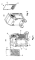
- the Figures 1 and 2 show from different perspectives a filter device 100 for room air filtration for renovation work in buildings.
- the filter device 100 includes a housing 10 in which a dust filter 11 is disposed, as in FIG Fig. 3 is shown.
- the filter 11 is a fine filter, namely a hollow cylindrical HEPA filter.
- the filter is arranged in a box-shaped filter chamber 12 of the housing 11 or is fastened there.
- the filter chamber 12 is delimited by four wall sides 13 to 16, which in the Fig. 10 Marked are.
- the wall side 13 is a closed rear side, whereas the sides 14 to 16 are filter sides.
- the wall sides 14 to 16 of the filter chamber 12 form air inlet sides. These comprise a window-like frame 17, which forms an opening 18.
- Each of the three openings 18 can be covered by a coarse filter 19.
- Fig. 1 shows that the filter 19 has been removed from the side 15 and that the coarse filter is mounted on the side 16.
- the filter 19 comprises a filter holder 20, in which a filter plate 21 is inserted, as the Figures 1 and 2 illustrate.
- the filter holder 20 has a lattice structure, wherein the filter plate 21 lies downstream in the flow direction.
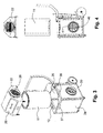
- a housing cover 22 is arranged, which in the FIGS. 3 and 4 is shown exploded.
- the housing cover 22 is removable and / or hinged. That is, the housing cover 22 is designed lid-like, to release the filter chamber 12.
- open state Fig. 3, Fig. 4
- the fine filter 11 can be removed through a filter opening 25 of the housing 10.
- FIG. 3 On the housing cover 22, two air outlet openings 26, 27 are arranged.
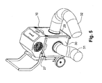
- An air outlet opening 26 is eg in Fig. 3 to see while the other air outlet opening 27 eg in Fig. 5 is shown.
- a fan or blower is housed in the area of the housing cover 22 in the area of the housing cover 22, a fan or blower is housed.
- control and / or display elements are mounted to switch eg different fan stages or to realize a level indicator or filter change indicator.
- the device 100 thus comprises a HEPA filter and a fan for dust extraction, wherein the housing is provided with a plurality of air inlet sides or wall sides 14 to 16 and two air outlet openings 26, 27 for blowing out the sucked into the housing 10 by the fan air.
- the fan generates a negative pressure on each air outlet side.
- one or more air inlet sides or wall sides 14 to 16 have a detachable adapter plate 29 or 30 (cf. Fig. 3 . Fig. 5 ) for a suction hose 31 or 32 or a detachable cover plate 33, 34 or 35 fastened (see. Fig. 3 . Fig. 9 . Fig. 13 ), so that at one or more air inlet sides either a free air intake at not mounted adapter plate 29, 30 or cover plate 33, 34, 35 (see. Fig. 1 and Fig. 2 ) or suction through a suction hose 31 or 32 with mounted adapter plate 29, 30 is possible.
- Fig. 1 a first mode of operation is shown, in which the filter device with only the filters 19 on all three sides 14, 15, 16 (see. Fig. 10 ) Is provided. There is thus a free air intake at not mounted adapter plate 29, 30 or cover plate 33 - 35 shown.
- Fig. 5 shows a second mode of operation in which two tubes 31, 32 are connected to the housing 10. These suction hoses 31, 32 are led to a workstation, where the dust to be sucked off, eg as a result of grinding work, arises.
- the adapter plates 29, 30 are simply attached via the filters 19.
- the adapter plates 29, 30 are detachable and expediently provided with a handle 36, 37 ( Fig. 3 ). To generate the required negative pressure, it is necessary to cover the third side. This is done with the cover plate eg 30. In Fig. 3 It is shown how the front side is closed with the cover plate 34. Because the adapter plates 29, 30 are above the filter 19, the filter effect of the coarse filter is maintained.
- Each adapter plate 29, 30 consists of a metal plate which lies in or on the frame.
- the sheet metal plate has a e.g. circular opening 40 which carries an adapter ring 41, on which the tube 31, 32 can be inserted.
- the adapter ring 41 may be used together with the tube 31, 32 via a positive and / or non-positive connection, e.g. a screw or bayonet connection to be attached to the housing.
- Corresponding adapter rings can also be used for the openings 26, 27, as Fig. 3 shows.
- Fig. 1 shows, but can not be attached to either side of an adapter plate 29, 30 or a cover plate 33, 34.
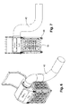
- FIGS. 6 and 7 illustrate that at the at least one air outlet opening 26, 27, a blow-out 42 is connected.
- two opposite air outlet openings 26, 27 are provided, wherein at each air outlet opening 26, 27, a blow-out 42 is connected. So it can be two Ausblasschläuche 42, 43, as Fig. 8 shows, to be connected. However, it is also possible for only one outlet hose 42 to be connected to an opening, for example, 26, in which case the other air outlet opening, for example, 27, can be connected by a closure element 44 which is in Fig. 9 shown can be covered.
- blow-out hoses 42, 43 can optionally be present at both air outlet openings 26, 27 blow-out hoses 42, 43 or it may be present only at an air outlet opening a blow-42.
- the filter device is designed as a filter car.
- two transport rollers 45 are fixed by a support member 46.
- two smaller support rollers 48 are provided on the underside of the housing.
- a pivotable transport bracket 47 is attached to the housing, this in eg Fig. 1 collapsed and in Fig. 3 unfolded is shown.
- Each tube 31, 32, 42, 43 may have a diameter of 150-400 mm and a length of 3 to 10 meters.
- the device can be designed for 1000 - 10000 m 3 / h.
- the filter device may also have a deviating from the figures housing shape, for example cylindrical.
- the sides or coarse filters therefore do not have to be flat, but can also be curved, so that the walls 13 - 16 can also be other surfaces.
- the air outlet may alternatively be mounted above and not laterally.
Abstract
Description
Die Erfindung betrifft eine Filtervorrichtung zur Raumluftfilterung nach dem Oberbegriff des Anspruches 1.The invention relates to a filter device for room air filtration according to the preamble of claim 1.
Derartige Luftreiniger für die Gebäudesanierung oder andere Anwendungen sorgen für eine staubfreie Luft beispielweise während einer Umbauphase. Die Luft zirkuliert durch einen Filter, wobei der in der Luft enthaltene gesundheitsgefährdete Staub aufgefangen und die Raumluft gereinigt wird.Such air cleaners for building renovation or other applications provide a dust-free air, for example, during a conversion phase. The air circulates through a filter, collecting the harmful dust contained in the air and cleaning the room air.
Aus dem Firmenprospekt beispielweise DC AirCube 2000 der Firma Dustcontrol® ist ein Luftreiniger für Sanierungsarbeiten bekannt, der als Filterwagen ausgeführt ist und einen Lufteinzug aufweist. Für einen Unterdruckaufbau in abgedichteten Räumen kann auf der Abluftseite ein 250mm-Entlüftungsschlauch eingesetzt werden. Dieses Gerät kann als Unterdruckhaltegerät eingesetzt werden.From the company brochure, for example DC AirCube 2000 from Dustcontrol ® , an air cleaner for renovation work is known, which is designed as a filter car and has an air intake. For a vacuum build-up in sealed rooms, a 250mm vent hose can be used on the exhaust side. This device can be used as a negative pressure device.
Bekannt sind auch Geräte, an denen ein Ansaugschlauch anschließbar ist. Der Ansaugschlauch kann an eine Arbeitsstelle geführt werden, wo der Staub bzw. die belastete Luft entsteht.Devices are also known in which a suction hose can be connected. The suction hose can be led to a workstation where the dust or contaminated air is produced.
Aus der
Der Erfindung liegt die Aufgabe zugrunde, eine Filtervorrichtung zu schaffen, die verschiedene Anwendungsmöglichkeiten in einem einzigen Gerät vereinigt.The invention has for its object to provide a filter device that combines different applications in a single device.
Diese Aufgabe wird durch eine Filtervorrichtung mit den kennzeichnenden Merkmalen des Anspruches 1 in Kombination mit seinen Oberbegriffsmerkmalen gelöst.This object is achieved by a filter device with the characterizing features of claim 1 in combination with its generic features.
In einem Grundzustand des erfindungsgemäßen Gerätes bzw. der Filtervorrichtung sind mehrere, vorzugsweise drei Seiten für den Lufteinzug offen. Die Luft wird vorzugsweise über Grobfilterflächen in das Gerät in einem Hauptfilter angesaugt. In diesem Modus dient das Gerät der Luftreinigung im Raum.In a basic state of the device according to the invention or the filter device are several, preferably three sides open to the air intake. The air is preferably sucked through coarse filter surfaces in the device in a main filter. In this mode, the device is used for air purification in the room.
Zusätzlich bietet die erfindungsgemäße Filtervorrichtung aber mindestens einen weiteren Arbeitsmodus. Bei Bedarf lassen sich z.B. alle drei Seiten mit z.B. einsteckbaren Abdeckblechen bzw. Adapterplatten verschließen. Zwei dieser Abdeckbleche sind (zumindest teilweise) mit Schlauchanschlüssen versehen. Die Abdeckbleche für die Ansaugschläuche weisen eine entsprechende Lufteintrittsöffnung auf. Diese sind quasi als Adapterplatten ausgeführt. Für einen erforderlichen Druckaufbau wird die dritte Seite mit einem geschlossenen Abdeckblech abgedeckt.In addition, however, the filter device according to the invention offers at least one further working mode. If necessary, e.g. all three sides with e.g. close plug-in cover plates or adapter plates. Two of these cover plates are (at least partially) provided with hose connections. The cover plates for the intake hoses have a corresponding air inlet opening. These are quasi designed as adapter plates. For a required pressure build-up, the third side is covered with a closed cover plate.
Anstelle des Anschlusses von zwei Schläuchen kann auch nur an einer Seite ein einziger Ansaugschlauch angeschlossen werden. Die beiden übrigen Seiten werden mit Abdeckblechen verschlossen.Instead of connecting two hoses, only one suction hose can be connected to one side. The other two sides are closed with cover plates.
Die anzuschließenden Schläuche lassen sich zum Arbeitsplatz im Raum führen, wo dann abgesaugt werden kann. Eine Staub-Absaugung am Arbeitsplatz ist deutlich effizienter als nur die reine Raumluftfilterung. Im Modus "mit Schlauchanschluss zur Arbeitsplatzabsaugung" sind dann die anderen Seiten (eine oder zwei) des Gerätes komplett zu verschließen, so dass sich in den Schläuchen genug Sog aufbaut. Nach Ende der Arbeiten lässt sich das Gerät zum Abtransport mit allen drei Abdeckblechen (jeweils ohne Schlauchstutzen) fest verschließen, so dass kein Staub austritt.The hoses to be connected can be led to the workplace in the room, where it can be sucked off. A dust extraction at the workplace is much more efficient than just pure room air filtration. In the mode "with hose connection for workplace extraction" then the other sides (one or two) of the device must be completely closed, so that enough suction builds up in the hoses. After the work has been completed, the device can be closed tightly with all three cover plates (each without hose connection) so that no dust escapes.
Mit der Filtervorrichtung lassen sich verschiedene Funktionen mit einem einzigen Gerät realisieren.With the filter device, various functions can be realized with a single device.
Die verschiedenen Funktionen lassen sich dadurch realisieren, dass an einer oder mehreren Lufteintrittsseiten eine loslösbare Adapterplatte, z.B. ein Abdeckblech mit einer Öffnung bzw. mit einem Anschluss für einen Ansaugschlauch oder eine loslösbare Abdeckplatte (z.B. Abdeckblech) befestigbar ist, derart dass an einer oder mehreren Lufteintrittsseiten wahlweise eine freie Luftansaugung bei nicht montierter Adapterplatte bzw. Abdeckplatte oder eine Ansaugung durch einen Ansaugschlauch bei montierter Adapterplatte möglich ist.The various functions can be realized in that at one or more air inlet sides, a detachable adapter plate, such as a cover plate with an opening or with a connection for a suction hose or a detachable cover plate (eg cover plate) can be fastened, such that at one or more air inlet sides optionally a free one Air intake is possible when the adapter plate or cover plate is not mounted, or it can be suctioned through a suction hose with the adapter plate mounted.
Durch die austauschbaren Seitenwände - einmal geschlossen, einmal mit Schlauchanschluss - ist die Möglichkeit geschaffen worden, beide Funktionen, d.h. freie Luftfilterung und Schlauchansaugung, mit einem Gerät zu erfüllen.The interchangeable side walls - once closed, once with hose connection - have created the possibility of both functions, i. free air filtration and hose suction to comply with a device.
Die erfindungsgemäße Filtervorrichtung ist beispielsweise für das Abscheiden von Fein- und Gefahrenstaub bis zu einer Größe von etwa 0,3 Mikrometer geeignet. Diese Partikelgröße ist z.B. bei Quarzstaub, der in Beton, Ziegelsteinen oder Mörtel enthalten ist, vorhanden.The filter device according to the invention is suitable for example for the separation of fine and hazardous dust up to a size of about 0.3 microns. This particle size is e.g. fumed silica contained in concrete, bricks or mortar.
Eingesetzt werden kann der Luftfilter bei Arbeiten wie Abrissarbeiten Wandschleifen, Betonschleifen, Küchenrenovierungen oder Badrenovierungen.The air filter can be used for work such as demolition, wall grinding, concrete grinding, kitchen renovation or bathroom renovation.
Weitere vorteilhafte Ausgestaltungen der Erfindung sind in den Unteransprüchen gekennzeichnet.Further advantageous embodiments of the invention are characterized in the subclaims.
In einer vorteilhaften Weiterbildung der erfindungsgemäßen Vorrichtung ist vorgesehen, dass an der mindestens einen Luftaustrittsöffnung ein Ausblasschlauch anschließbar ist. Mit diesem Ausblasschlauch kann eine zusätzliche Unterdruckfunktion realisiert werden. Durch den Unterdruck kann Frischluft in einen Raum eintreten, wobei die ausgeblasene Luft gereinigt aus den Raum austritt. Durch die Frischluft wird das Raumklima deutlich verbessert.In an advantageous development of the device according to the invention, it is provided that a discharge hose can be connected to the at least one air outlet opening. With this blow-out hose, an additional vacuum function can be realized. The negative pressure allows fresh air to enter a room with the purged air coming out of the room in a clean condition. The fresh air significantly improves the indoor climate.
Eine Lösung zur flexiblen Anwendung der Unterdruckfunktion wird dadurch geschaffen, dass wenigstens zwei Luftaustrittsöffnungen vorhanden sind. Bevorzugterweise ist mindestens ein Ausblasschlauch anschließbar. Es ist wahlweise an allen beiden Luftaustrittsöffnungen ein Ausblasschlauch vorhanden oder nur an einer Luftaustrittsöffnung ein Ausblasschlauch vorhanden. Die andere Luftaustrittsöffnung wird bei Anschluss eines einzigen Ausblasschlauches dann durch ein Verschlusselement abgedeckt. Durch mehrere Schläuche können mehrere Luftaustrittstellen, z.B. zwei Fenster, gleichzeitig genutzt werden. Alternativ kann nur ein Schlauch verwendet werden, um nur ein Fenster zu nutzen. Anstelle eines oder mehrerer Fenster können auch Türen genutzt werden.A solution for flexible application of the vacuum function is created by the fact that at least two air outlet openings are present. Preferably, at least one outlet hose can be connected. It is optionally available at all two air outlet openings a Ausblasschlauch or only at an air outlet opening a Ausblasschlauch available. The other air outlet opening is then covered by a closure element when connecting a single exhaust hose. Through several hoses several air outlet points, e.g. two windows, used simultaneously. Alternatively, only one hose can be used to use only one window. Instead of one or more windows, doors can also be used.
Von Vorteil ist es, wenn insgesamt zwei gegenüberliegende Ausblasöffnungen am Gehäuse vorhanden sind. Diese sorgt für eine gleichmäßige und effektive Luftströmung. Wenn eines der Luftaustrittsöffnungen des Gehäuses abgedeckt wird, dann ist der Ausblasschlauch L-förmig angeschlossen.It is advantageous if a total of two opposing exhaust openings are present on the housing. This ensures a uniform and effective air flow. If one of the air outlet openings of the housing is covered, then the discharge hose is connected in an L-shape.
Eine besonders bevorzugte Weiterbildung der Erfindung zeichnet sich dadurch aus, dass an jeder Lufteintrittsseite ein Grob- oder Vorfilter befestigbar ist. Dieser Filter kann sowohl für die Absaugung durch einen Ansaugschlauch als auch für eine freie Ansaugung, d.h. direkt in das Gehäuse, genutzt werden. Durch diesen Grobfilter bzw. Vorfilter wird die Lebensdauer des HEPA-Filters deutlich verlängert. Der Grob- oder Vorfilter hat vorzugsweise einen Filterhalter mit einer Gitterstruktur und eine in Strömungsrichtung dahinter liegende Filterplatte. Somit wird durch verschiedene Filter für verschiedene Partikelgrößen die Filterwirkung bei zeitlich konstantem Luftvolumen verbessert. Der Feinfilter bzw. Mikrofilter (HEPA-Filter) ist im Gehäuse angeordnet und ist hohlzylinderartig ausgeführt. Durch die Filterplatten in Kombination mit der Zylinderform lassen sich relativ große Filterflächen bei kompakten Geräteabmessungen realisieren. Jeder Grobfilter kann z.B. eine Fläche von 0,5 m2 - 1,2 m2 aufweisen, wobei der Mikrofilter (HEPA-Filter) eine Gesamtfilterfläche von 5 m2 bis 15 m2 hat.A particularly preferred development of the invention is characterized in that a coarse filter or prefilter can be fastened to each air inlet side. This filter can be used both for suction through a suction hose and for a free intake, ie directly into the housing. This coarse filter or pre-filter significantly prolongs the life of the HEPA filter. The coarse or prefilter preferably has a filter holder with a grid structure and a downstream filter plate in the flow direction. Thus, the filter effect is improved by temporally constant air volume through different filters for different particle sizes. The fine filter or microfilter (HEPA filter) is arranged in the housing and is designed like a hollow cylinder. Due to the filter plates in combination with the cylindrical shape, relatively large filter surfaces can be realized with compact device dimensions. Each coarse filter may have, for example, an area of 0.5 m 2 - 1.2 m 2 , wherein the microfilter (HEPA filter) has a total filter area of 5 m 2 to 15 m 2 .
Bei einer weiteren vorteilhaften Ausführung der Erfindung ist das Gehäuse mit insgesamt drei Lufteintrittsseiten versehen. Die Filterseiten sind z.B. Wände eine Filterkastens und können variabel eingesetzt werden. Es können alle drei Seiten zur freien bzw. direkten Filterung eingesetzt werden. Alternativ kann nur eine Seite zur Schlauchabsaugung eingesetzt werden, wobei der Schlauch zur Arbeitsstelle z.B. in die Nähe eines Schleifgerätes geführt wird. Bei einem Schlauch werden die anderen Seiten verschlossen. Alternativ können aber auch zwei Seiten mit einem Schlauch versehen werden. Dann wird nur eine Seite geschlossen. Grundsätzlich könnten sogar alle drei Seiten mit einem Schlauch versehen werden. Somit ist es zweckmäßig, dass an dem Gehäuse wahlweise nur eine Adapterplatte mit einem Ansaugschlauch befestigbar ist, während die beiden übrigen Lufteintrittsseiten mit Abdeckplatten versehen werden, und dass an dem Gehäuse wahlweise zwei der drei Lufteintrittsseiten mit einer Adapterplatte mit Ansaugschlauch versehen werden können, während die dritte Lufteintrittsseite mit einer Abdeckplatte versehen wird, wobei aber auch an keiner Seite eine Adapterplatte oder eine Abdeckplatte befestigt sein können, so dass alle drei Seiten als freie Ansaugseiten wählbar sind.In a further advantageous embodiment of the invention, the housing is provided with a total of three air inlet sides. The filter sides are eg walls of a filter box and can be used variably. All three sides can be used for free or direct filtering. Alternatively, only one side for Schlauchabsaugung be used, the hose is led to the workplace, for example in the vicinity of a grinder. With a hose, the other sides are closed. Alternatively, however, two sides can be provided with a hose. Then only one side is closed. In principle, even all three sides could be provided with a hose. Thus, it is expedient that on the housing optionally only an adapter plate with a suction hose is fastened, while the other two air inlet sides are provided with cover plates, and that on the housing optionally two of the three air inlet sides can be provided with an adapter plate with suction hose while the third air inlet side is provided with a cover plate, but also an adapter plate or a cover plate can not be attached to either side, so that all three sides can be selected as free intake sides.
Um den Transport von einer Arbeitsstelle zu einer anderen Stelle zu vereinfachen, ist die Filtervorrichtung als Filterwagen ausgeführt.In order to simplify the transport from one job to another job, the filter device is designed as a filter car.
Eine besonders bevorzugte Weiterbildung der Erfindung zeichnet sich dadurch aus, dass das Gehäuse einen kistenförmigen Filterraum umfasst, in dem ein Staubfilter befestigbar ist, wobei mehrere Wandseiten des Filterraumes die Lufteintrittsseiten bilden, und dass über den Filterraum eine Gehäusehaube angeordnet ist, die deckelartig ausgeführt ist, um den Filterraum freizugeben, wobei an der Gehäusehaube die wenigstens eine Luftaustrittsöffnung angeordnet ist. Die kistenartige Konstruktion schafft einerseits eine optimale Unterbringung der Komponenten, wobei die Filter in einfacher und bequemer Weise ausgetauscht bzw. gereinigt werden können.A particularly preferred embodiment of the invention is characterized in that the housing comprises a box-shaped filter chamber in which a dust filter can be fastened, wherein a plurality of wall sides of the filter chamber form the air inlet sides, and that over the filter chamber, a housing hood is arranged, which is designed like a lid, to release the filter chamber, wherein on the housing cover the at least one air outlet opening is arranged. On the one hand, the box-like construction provides optimum accommodation of the components, and the filters can be exchanged or cleaned in a simple and convenient manner.
Ein Ausführungsbeispiel wird anhand der Zeichnungen näher erläutert, wobei weitere vorteilhafte Weiterbildungen der Erfindung und Vorteile derselben beschrieben sind.An embodiment will be explained in more detail with reference to the drawings, wherein further advantageous developments of the invention and advantages thereof are described.
Es zeigen:
-
Fig. 1 eine erste perspektivische Darstellung der Filtervorrichtung im freien Saugmodus, -
Fig. 2 eine zweite perspektivische Darstellung der Filtervorrichtung im freien Saugmodus, -
Fig. 3 eine perspektivische Explosionsdarstellung der Filtervorrichtung, -
Fig. 4 eine Explosionsdarstellung der Filtervorrichtung von der Seite gesehen, -
Fig. 5 eine perspektivische Darstellung der Filtervorrichtung im Schlauch-Saugmodus, -
Fig. 6 eine perspektivische Darstellung der Filtervorrichtung im Unterdruckmodus, -
Fig. 7 eine Seitendarstellung der Filtervorrichtung im Unterdruckmodus, -
Fig. 8 eine perspektivische Darstellung der Filtervorrichtung im Schlauch-Saugmodus und Unterdruckmodus, -
Fig. 9 eine erste perspektivische Darstellung der Filtervorrichtung im Transportmodus -
Fig. 10 eine Darstellung der Filtervorrichtung von unten gesehen, -
Fig. 11 eine Darstellung der Filtervorrichtung von einer Seite gesehen, -
Fig. 12 eine Darstellung der Filtervorrichtung von der Frontseite gesehen, und -
Fig. 13 eine zweite perspektivische Darstellung der Filtervorrichtung im Transportmodus.
-
Fig. 1 a first perspective view of the filter device in the free suction mode, -
Fig. 2 a second perspective view of the filter device in the free suction mode, -
Fig. 3 an exploded perspective view of the filter device, -
Fig. 4 an exploded view of the filter device seen from the side, -
Fig. 5 a perspective view of the filter device in the hose suction mode, -
Fig. 6 a perspective view of the filter device in the vacuum mode, -
Fig. 7 a side view of the filter device in the vacuum mode, -
Fig. 8 a perspective view of the filter device in the hose suction mode and vacuum mode, -
Fig. 9 a first perspective view of the filter device in the transport mode -
Fig. 10 an illustration of the filter device seen from below, -
Fig. 11 an illustration of the filter device seen from one side, -
Fig. 12 an illustration of the filter device seen from the front, and -
Fig. 13 a second perspective view of the filter device in the transport mode.
In den Figuren sind gleiche Teile mit denselben Bezugszeichen versehen.In the figures, like parts are given the same reference numerals.
Die
Die Filtervorrichtung 100 umfasst ein Gehäuse 10, in dem ein Staubfilter 11 angeordnet ist, wie in
Der Filter 19 umfasst eine Filterhalterung 20, in die eine Filterplatte 21 einschiebbar ist, wie die
Über den Filterraum 12 ist eine Gehäusehaube 22 angeordnet, die in den
An der Gehäusehaube 22 sind zwei Luftaustrittsöffnungen 26, 27 angeordnet. Eine Luftaustrittsöffnung 26 ist z.B. in
Im Bereich der Gehäusehaube 22 ist ein Ventilator bzw. Gebläse untergebracht. An einer Außenfrontseite 28, die z.B. in
Die Vorrichtung 100 umfasst also ein HEPA-Filter und ein Ventilator zur Staubabsaugung, wobei das Gehäuse mit mehreren Lufteintrittsseiten bzw. Wandseiten 14 bis 16 sowie mit zwei Luftaustrittsöffnungen 26, 27 zum Ausblasen der in das Gehäuse 10 durch den Ventilator angesaugten Luft versehen ist. Der Ventilator erzeugt an jeder Luftaustrittsseite einen Unterdruck.The
Erfindungsgemäß ist an einer oder mehreren Lufteintrittsseiten bzw. Wandseiten 14 bis 16 eine loslösbare Adapterplatte 29 bzw. 30 (vgl.
In
Nicht gezeigt, jedoch möglich ist der Anschluss nur eines einzigen Schlauches, und zwar an der Seite 14, 15 oder 16. In diesem Fall werden die anderen Seiten durch Abdeckplatten abgedeckt.Not shown, but it is possible to connect only a single hose, on the
Jede Adapterplatte 29, 30 besteht aus einer Blechplatte, die in oder auf dem Rahmen liegt. Die Blechplatte hat eine z.B. kreisförmige Öffnung 40, die einen Adapterring 41 trägt, auf den der Schlauch 31, 32 gesteckt werden kann. Der Adapterring 41 kann zusammen mit dem Schlauch 31, 32 über eine form-und/oder kraftschlüssige Verbindung, z.B. eine Schraub- oder Bajonettverbindung, am Gehäuse befestigt werden.Each
Entsprechende Adapterringe können auch für die Öffnungen 26, 27 verwendet werden, wie
An dem Gehäuse 10 ist somit wahlweise nur eine Adapterplatte z.B. 30 mit einem Ansaugschlauch 31 befestigbar, während die beiden übrigen Lufteintrittsseiten mit Abdeckplatten 33, 34 versehen werden. An dem Gehäuse 10 können auch wahlweise zwei der drei Lufteintrittsseiten mit einer Adapterplatte 29, 30 mit Ansaugschlauch 31, 32 versehen werden, während die dritte Lufteintrittsseite mit einer Abdeckplatte 34 versehen wird. Wie
Die
Vorzugsweise sind zwei gegenüberliegende Luftaustrittsöffnungen 26, 27 vorhanden, wobei an jeder Luftaustrittsöffnung 26, 27 ein Ausblasschlauch 42 anschließbar ist. Es können also zwei Ausblasschläuche 42, 43, wie
Es können also wahlweise an beiden Luftaustrittsöffnungen 26, 27 Ausblasschläuche 42, 43 vorhanden sein oder es kann nur an einer Luftaustrittsöffnung ein Ausblasschlauch 42 vorhanden sein.Thus, it can optionally be present at both
Insgesamt ergeben sich folgende Kombinationsmöglichkeiten:
- Freie Lufteinsaugung und freie Luftausblasung gemäß
Fig. 1 . - Lufteinsaugung mit einem oder mehreren Schläuchen und freie Luftausblasung gemäß
Fig. 5 . - Freie Lufteinsaugung und Luftausblasung mit einem oder mehreren Ausblasschläuchen gemäß
Fig. 6 . - Lufteinsaugung mit einem oder mehreren Schläuchen und Luftausblasung mit einem oder mehren Ausblasschläuchen gemäß
Fig. 8 . - Verschluss aller Öffnungen mit Abdeckplatten 33 - 35 und Verschlusselementen 44 z.B. zu Transportzwecken gemäß
Fig. 9 - 12 .
- Free air intake and free air blow-out according to
Fig. 1 , - Air intake with one or more hoses and free air blow-out according to
Fig. 5 , - Free air intake and air discharge with one or more outlet hoses according to
Fig. 6 , - Air intake with one or more hoses and air blow with one or more Ausblasschläuchen according to
Fig. 8 , - Closure of all openings with cover plates 33-35 and
closure elements 44 eg for transport purposes according toFig. 9 - 12 ,
Wie die Figuren zeigen, ist die Filtervorrichtung als Filterwagen ausgeführt. An der Rückseite 13 sind zwei Transportrollen 45 durch ein Trägerelement 46 befestigt. Zusätzlich zu den Hauptrollen bzw. Transportrollen 45 sind zwei kleinere Stützrollen 48 an der Gehäuseunterseite vorhanden.As the figures show, the filter device is designed as a filter car. At the rear 13, two
Zudem ist ein schwenkbarer Transportbügel 47 am Gehäuse befestigt, wobei dieser in z.B.
Jeder Schlauch 31, 32, 42, 43 kann einen Durchmesser von 150-400 mm und eine Länge von 3 bis 10 Meter haben. Die Vorrichtung kann für 1000 - 10000 m3/h ausgelegt sein.Each
Die Erfindung ist nicht auf dieses Beispiel beschränkt, so kann die Filtervorrichtung auch eine von den Figuren abweichende Gehäuseform haben z.B. zylinderförmig. Die Seiten bzw. Grobfilter müssen also nicht flach sein, sondern können auch gekrümmt sein, so dass die Wände 13 - 16 auch andere Flächen sein können. Der Luftauslass kann auch alternativ oben und nicht seitlich angebracht sein.The invention is not limited to this example, so the filter device may also have a deviating from the figures housing shape, for example cylindrical. The sides or coarse filters therefore do not have to be flat, but can also be curved, so that the walls 13 - 16 can also be other surfaces. The air outlet may alternatively be mounted above and not laterally.
- 1010
- Gehäusecasing
- 1111
- Staubfilterdust filter
- 1212
- Filterraumfilter chamber
- 13-1613-16
- Wandseitenwall sides
- 1717
- Rahmenframe
- 1818
- Erste ÖffnungFirst opening
- 1919
- Grobfiltercoarse filter
- 2020
- Filterhalterungfilter holder
- 2121
- Filterplattefilter plate
- 2222
- GehäusehaubeBody cap
- 23, 2423, 24
- --
- 2525
- Filteröffnungfilter opening
- 26, 2726, 27
- LuftaustrittsöffnungenAir outlet openings
- 2828
- AußenfrontseiteExterior Front
- 29, 3029, 30
- Adapterplattenadapter plates
- 31, 3231, 32
- Ansaugschläuchesuction hoses
- 33 - 3533 - 35
- Abdeckplattencover
- 36, 3736, 37
- Griffehandles
- 38, 3938, 39
- --
- 4040
- Zweite ÖffnungSecond opening
- 4141
- Adapterringadapter ring
- 42,4342.43
- AusblasschläucheAusblasschläuche
- 4444
- Verschlusselementclosure element
- 4545
- Transportrollentransport wheels
- 4646
- Trägerelementsupport element
- 4747
- Transportbügeltransport bracket
- 4848
- Stützrollensupport rollers
- 100100
- Filtervorrichtungfilter means
Claims (10)
Applications Claiming Priority (1)
| Application Number | Priority Date | Filing Date | Title |
|---|---|---|---|
| DE202011050155U DE202011050155U1 (en) | 2011-05-17 | 2011-05-17 | Filter device for room air filtration, especially for renovation work in buildings |
Publications (3)
| Publication Number | Publication Date |
|---|---|
| EP2524739A2 true EP2524739A2 (en) | 2012-11-21 |
| EP2524739A3 EP2524739A3 (en) | 2013-05-08 |
| EP2524739B1 EP2524739B1 (en) | 2016-04-06 |
Family
ID=46052604
Family Applications (1)
| Application Number | Title | Priority Date | Filing Date |
|---|---|---|---|
| EP12166329.8A Active EP2524739B1 (en) | 2011-05-17 | 2012-05-02 | Filter device for filtering the air of a room, in particular for renovation work in buildings |
Country Status (2)
| Country | Link |
|---|---|
| EP (1) | EP2524739B1 (en) |
| DE (1) | DE202011050155U1 (en) |
Cited By (4)
| Publication number | Priority date | Publication date | Assignee | Title |
|---|---|---|---|---|
| CN108291736A (en) * | 2016-05-23 | 2018-07-17 | 翰昂汽车零部件有限公司 | Movable air regulating device |
| EP3714998A1 (en) | 2019-03-25 | 2020-09-30 | Demto B.V. | Suction device for a decontamination system |
| EP3879193A1 (en) * | 2020-03-10 | 2021-09-15 | TrustFilter UG (haftungsbeschränkt) | Room air cleaner |
| WO2023230369A1 (en) * | 2022-05-27 | 2023-11-30 | Mullet Tools, LLC | Air scrubber |
Families Citing this family (4)
| Publication number | Priority date | Publication date | Assignee | Title |
|---|---|---|---|---|
| CN106679009A (en) * | 2017-03-08 | 2017-05-17 | 嵊州亿源投资管理有限公司 | Efficient purifier |
| AT16330U1 (en) * | 2018-05-23 | 2019-07-15 | Kluge Anton | A filter assembly |
| DE102019008639A1 (en) * | 2019-12-13 | 2021-06-17 | Trotec Gmbh | Fan attachment for a device for room temperature control and / or room ventilation as well as a correspondingly equipped device |
| DE102020001913A1 (en) * | 2020-03-24 | 2021-09-30 | Trotec Gmbh | Turbo machine as well as control for and use of a turbo machine |
Citations (1)
| Publication number | Priority date | Publication date | Assignee | Title |
|---|---|---|---|---|
| DE102008013383A1 (en) | 2008-03-10 | 2009-09-17 | Edgar Gummerum | Method for cleaning microbial chemically contaminated wall, ceiling, floor, lumber, loaded surface and fixture of building, involves implementing air interchange and sanitation monitoring and clearing of space with sanitized area |
Family Cites Families (4)
| Publication number | Priority date | Publication date | Assignee | Title |
|---|---|---|---|---|
| US3023447A (en) * | 1958-10-15 | 1962-03-06 | Edgar P Senne | Wall-installed vacuum cleaner |
| US4749390A (en) * | 1987-02-26 | 1988-06-07 | Air Purification Products, International | Four-sided air filter |
| US6395047B1 (en) * | 2001-02-16 | 2002-05-28 | William C. Smith | Portable airborne contamination control system including a main and remote unit |
| DE202007014276U1 (en) * | 2007-10-11 | 2008-02-21 | Nexus Ag Plc Limited | Heat recovery unit, especially for Zentralstaubsauganlagen and other home appliances working with moving air |
-
2011
- 2011-05-17 DE DE202011050155U patent/DE202011050155U1/en not_active Expired - Lifetime
-
2012
- 2012-05-02 EP EP12166329.8A patent/EP2524739B1/en active Active
Patent Citations (1)
| Publication number | Priority date | Publication date | Assignee | Title |
|---|---|---|---|---|
| DE102008013383A1 (en) | 2008-03-10 | 2009-09-17 | Edgar Gummerum | Method for cleaning microbial chemically contaminated wall, ceiling, floor, lumber, loaded surface and fixture of building, involves implementing air interchange and sanitation monitoring and clearing of space with sanitized area |
Cited By (5)
| Publication number | Priority date | Publication date | Assignee | Title |
|---|---|---|---|---|
| CN108291736A (en) * | 2016-05-23 | 2018-07-17 | 翰昂汽车零部件有限公司 | Movable air regulating device |
| EP3714998A1 (en) | 2019-03-25 | 2020-09-30 | Demto B.V. | Suction device for a decontamination system |
| NL1043205B1 (en) * | 2019-03-25 | 2020-10-02 | Demto B V | Extractor for a remediation system |
| EP3879193A1 (en) * | 2020-03-10 | 2021-09-15 | TrustFilter UG (haftungsbeschränkt) | Room air cleaner |
| WO2023230369A1 (en) * | 2022-05-27 | 2023-11-30 | Mullet Tools, LLC | Air scrubber |
Also Published As
| Publication number | Publication date |
|---|---|
| EP2524739A3 (en) | 2013-05-08 |
| EP2524739B1 (en) | 2016-04-06 |
| DE202011050155U1 (en) | 2012-08-20 |
Similar Documents
| Publication | Publication Date | Title |
|---|---|---|
| EP2524739B1 (en) | Filter device for filtering the air of a room, in particular for renovation work in buildings | |
| EP3457047B1 (en) | Personalised air purification device | |
| DE202013011735U1 (en) | Device for cleaning the room air | |
| EP0211383A1 (en) | Filtering apparatus | |
| DE112011101402T5 (en) | Ventilation device for windows with air cleaning function | |
| EP1959200A2 (en) | device for air-conditioning and removal of air in a room | |
| EP1506805A1 (en) | Air cleaning device | |
| DE202016105466U1 (en) | Multilayered ionizing dedusting combined fresh air air cleaning system | |
| DE202021100433U1 (en) | Air filter arrangement for cleaning and disinfecting air | |
| DE102015010979A1 (en) | Mobile dedusting device | |
| DE202020105240U1 (en) | Air purification device for filtering room air | |
| DE202014010481U1 (en) | filter means | |
| EP3189760A1 (en) | Floor cleaning machine | |
| DE3526793A1 (en) | Air purification apparatus | |
| DE3719734A1 (en) | Filter unit | |
| AT16620U2 (en) | Device for cleaning dust-laden components | |
| CH653267A5 (en) | Device for purifying gaseous media | |
| DE2913871A1 (en) | Vacuum cleaner system for light-industry workbenches - has silent running fan with wide suction area covering entire waste collector | |
| DE202004008804U1 (en) | Portable filtered extract wall for spray operations has upper and lower filter boxes linked by a hinge and with an aperture over the upper filter | |
| DE3042457C2 (en) | ||
| DE202024100379U1 (en) | Air filter for 3D printer housing | |
| DE202021102865U1 (en) | Device for cleaning air, in particular for removing potentially virus-laden lung aerosols from room air | |
| DE102021111081A1 (en) | Air filtration device | |
| DE102020002180A1 (en) | SYSTEM FOR VENTILATION OF INDIVIDUAL WORKPLACES TO AVOID DROPLET INFECTION | |
| WO2022079069A1 (en) | Cleaning device and use |
Legal Events
| Date | Code | Title | Description |
|---|---|---|---|
| PUAI | Public reference made under article 153(3) epc to a published international application that has entered the european phase |
Free format text: ORIGINAL CODE: 0009012 |
|
| AK | Designated contracting states |
Kind code of ref document: A2 Designated state(s): AL AT BE BG CH CY CZ DE DK EE ES FI FR GB GR HR HU IE IS IT LI LT LU LV MC MK MT NL NO PL PT RO RS SE SI SK SM TR |
|
| AX | Request for extension of the european patent |
Extension state: BA ME |
|
| PUAL | Search report despatched |
Free format text: ORIGINAL CODE: 0009013 |
|
| AK | Designated contracting states |
Kind code of ref document: A3 Designated state(s): AL AT BE BG CH CY CZ DE DK EE ES FI FR GB GR HR HU IE IS IT LI LT LU LV MC MK MT NL NO PL PT RO RS SE SI SK SM TR |
|
| AX | Request for extension of the european patent |
Extension state: BA ME |
|
| RIC1 | Information provided on ipc code assigned before grant |
Ipc: B01D 35/30 20060101ALI20130403BHEP Ipc: F24F 7/00 20060101ALI20130403BHEP Ipc: B08B 15/00 20060101AFI20130403BHEP Ipc: F24F 3/16 20060101ALI20130403BHEP |
|
| 17P | Request for examination filed |
Effective date: 20130813 |
|
| RBV | Designated contracting states (corrected) |
Designated state(s): AL AT BE BG CH CY CZ DE DK EE ES FI FR GB GR HR HU IE IS IT LI LT LU LV MC MK MT NL NO PL PT RO RS SE SI SK SM TR |
|
| 17Q | First examination report despatched |
Effective date: 20140929 |
|
| GRAP | Despatch of communication of intention to grant a patent |
Free format text: ORIGINAL CODE: EPIDOSNIGR1 |
|
| INTG | Intention to grant announced |
Effective date: 20151202 |
|
| GRAS | Grant fee paid |
Free format text: ORIGINAL CODE: EPIDOSNIGR3 |
|
| GRAA | (expected) grant |
Free format text: ORIGINAL CODE: 0009210 |
|
| AK | Designated contracting states |
Kind code of ref document: B1 Designated state(s): AL AT BE BG CH CY CZ DE DK EE ES FI FR GB GR HR HU IE IS IT LI LT LU LV MC MK MT NL NO PL PT RO RS SE SI SK SM TR |
|
| REG | Reference to a national code |
Ref country code: GB Ref legal event code: FG4D Free format text: NOT ENGLISH |
|
| REG | Reference to a national code |
Ref country code: AT Ref legal event code: REF Ref document number: 787167 Country of ref document: AT Kind code of ref document: T Effective date: 20160415 Ref country code: CH Ref legal event code: EP |
|
| REG | Reference to a national code |
Ref country code: IE Ref legal event code: FG4D Free format text: LANGUAGE OF EP DOCUMENT: GERMAN |
|
| REG | Reference to a national code |
Ref country code: DE Ref legal event code: R096 Ref document number: 502012006557 Country of ref document: DE |
|
| REG | Reference to a national code |
Ref country code: LT Ref legal event code: MG4D Ref country code: NL Ref legal event code: MP Effective date: 20160406 |
|
| PG25 | Lapsed in a contracting state [announced via postgrant information from national office to epo] |
Ref country code: BE Free format text: LAPSE BECAUSE OF NON-PAYMENT OF DUE FEES Effective date: 20160531 |
|
| PG25 | Lapsed in a contracting state [announced via postgrant information from national office to epo] |
Ref country code: NL Free format text: LAPSE BECAUSE OF FAILURE TO SUBMIT A TRANSLATION OF THE DESCRIPTION OR TO PAY THE FEE WITHIN THE PRESCRIBED TIME-LIMIT Effective date: 20160406 |
|
| PG25 | Lapsed in a contracting state [announced via postgrant information from national office to epo] |
Ref country code: NO Free format text: LAPSE BECAUSE OF FAILURE TO SUBMIT A TRANSLATION OF THE DESCRIPTION OR TO PAY THE FEE WITHIN THE PRESCRIBED TIME-LIMIT Effective date: 20160706 Ref country code: PL Free format text: LAPSE BECAUSE OF FAILURE TO SUBMIT A TRANSLATION OF THE DESCRIPTION OR TO PAY THE FEE WITHIN THE PRESCRIBED TIME-LIMIT Effective date: 20160406 Ref country code: LT Free format text: LAPSE BECAUSE OF FAILURE TO SUBMIT A TRANSLATION OF THE DESCRIPTION OR TO PAY THE FEE WITHIN THE PRESCRIBED TIME-LIMIT Effective date: 20160406 Ref country code: FI Free format text: LAPSE BECAUSE OF FAILURE TO SUBMIT A TRANSLATION OF THE DESCRIPTION OR TO PAY THE FEE WITHIN THE PRESCRIBED TIME-LIMIT Effective date: 20160406 Ref country code: IS Free format text: LAPSE BECAUSE OF FAILURE TO SUBMIT A TRANSLATION OF THE DESCRIPTION OR TO PAY THE FEE WITHIN THE PRESCRIBED TIME-LIMIT Effective date: 20160806 |
|
| PG25 | Lapsed in a contracting state [announced via postgrant information from national office to epo] |
Ref country code: PT Free format text: LAPSE BECAUSE OF FAILURE TO SUBMIT A TRANSLATION OF THE DESCRIPTION OR TO PAY THE FEE WITHIN THE PRESCRIBED TIME-LIMIT Effective date: 20160808 Ref country code: LV Free format text: LAPSE BECAUSE OF FAILURE TO SUBMIT A TRANSLATION OF THE DESCRIPTION OR TO PAY THE FEE WITHIN THE PRESCRIBED TIME-LIMIT Effective date: 20160406 Ref country code: GR Free format text: LAPSE BECAUSE OF FAILURE TO SUBMIT A TRANSLATION OF THE DESCRIPTION OR TO PAY THE FEE WITHIN THE PRESCRIBED TIME-LIMIT Effective date: 20160707 Ref country code: RS Free format text: LAPSE BECAUSE OF FAILURE TO SUBMIT A TRANSLATION OF THE DESCRIPTION OR TO PAY THE FEE WITHIN THE PRESCRIBED TIME-LIMIT Effective date: 20160406 Ref country code: ES Free format text: LAPSE BECAUSE OF FAILURE TO SUBMIT A TRANSLATION OF THE DESCRIPTION OR TO PAY THE FEE WITHIN THE PRESCRIBED TIME-LIMIT Effective date: 20160406 Ref country code: HR Free format text: LAPSE BECAUSE OF FAILURE TO SUBMIT A TRANSLATION OF THE DESCRIPTION OR TO PAY THE FEE WITHIN THE PRESCRIBED TIME-LIMIT Effective date: 20160406 Ref country code: SE Free format text: LAPSE BECAUSE OF FAILURE TO SUBMIT A TRANSLATION OF THE DESCRIPTION OR TO PAY THE FEE WITHIN THE PRESCRIBED TIME-LIMIT Effective date: 20160406 |
|
| PG25 | Lapsed in a contracting state [announced via postgrant information from national office to epo] |
Ref country code: IT Free format text: LAPSE BECAUSE OF FAILURE TO SUBMIT A TRANSLATION OF THE DESCRIPTION OR TO PAY THE FEE WITHIN THE PRESCRIBED TIME-LIMIT Effective date: 20160406 |
|
| REG | Reference to a national code |
Ref country code: DE Ref legal event code: R097 Ref document number: 502012006557 Country of ref document: DE |
|
| PG25 | Lapsed in a contracting state [announced via postgrant information from national office to epo] |
Ref country code: DK Free format text: LAPSE BECAUSE OF FAILURE TO SUBMIT A TRANSLATION OF THE DESCRIPTION OR TO PAY THE FEE WITHIN THE PRESCRIBED TIME-LIMIT Effective date: 20160406 Ref country code: RO Free format text: LAPSE BECAUSE OF FAILURE TO SUBMIT A TRANSLATION OF THE DESCRIPTION OR TO PAY THE FEE WITHIN THE PRESCRIBED TIME-LIMIT Effective date: 20160406 Ref country code: CZ Free format text: LAPSE BECAUSE OF FAILURE TO SUBMIT A TRANSLATION OF THE DESCRIPTION OR TO PAY THE FEE WITHIN THE PRESCRIBED TIME-LIMIT Effective date: 20160406 Ref country code: SK Free format text: LAPSE BECAUSE OF FAILURE TO SUBMIT A TRANSLATION OF THE DESCRIPTION OR TO PAY THE FEE WITHIN THE PRESCRIBED TIME-LIMIT Effective date: 20160406 Ref country code: MC Free format text: LAPSE BECAUSE OF FAILURE TO SUBMIT A TRANSLATION OF THE DESCRIPTION OR TO PAY THE FEE WITHIN THE PRESCRIBED TIME-LIMIT Effective date: 20160406 Ref country code: EE Free format text: LAPSE BECAUSE OF FAILURE TO SUBMIT A TRANSLATION OF THE DESCRIPTION OR TO PAY THE FEE WITHIN THE PRESCRIBED TIME-LIMIT Effective date: 20160406 |
|
| PLBE | No opposition filed within time limit |
Free format text: ORIGINAL CODE: 0009261 |
|
| STAA | Information on the status of an ep patent application or granted ep patent |
Free format text: STATUS: NO OPPOSITION FILED WITHIN TIME LIMIT |
|
| REG | Reference to a national code |
Ref country code: IE Ref legal event code: MM4A |
|
| PG25 | Lapsed in a contracting state [announced via postgrant information from national office to epo] |
Ref country code: SM Free format text: LAPSE BECAUSE OF FAILURE TO SUBMIT A TRANSLATION OF THE DESCRIPTION OR TO PAY THE FEE WITHIN THE PRESCRIBED TIME-LIMIT Effective date: 20160406 |
|
| REG | Reference to a national code |
Ref country code: FR Ref legal event code: ST Effective date: 20170131 |
|
| 26N | No opposition filed |
Effective date: 20170110 |
|
| GBPC | Gb: european patent ceased through non-payment of renewal fee |
Effective date: 20160706 |
|
| PG25 | Lapsed in a contracting state [announced via postgrant information from national office to epo] |
Ref country code: FR Free format text: LAPSE BECAUSE OF NON-PAYMENT OF DUE FEES Effective date: 20160606 |
|
| PG25 | Lapsed in a contracting state [announced via postgrant information from national office to epo] |
Ref country code: SI Free format text: LAPSE BECAUSE OF FAILURE TO SUBMIT A TRANSLATION OF THE DESCRIPTION OR TO PAY THE FEE WITHIN THE PRESCRIBED TIME-LIMIT Effective date: 20160406 Ref country code: IE Free format text: LAPSE BECAUSE OF NON-PAYMENT OF DUE FEES Effective date: 20160502 Ref country code: GB Free format text: LAPSE BECAUSE OF NON-PAYMENT OF DUE FEES Effective date: 20160706 |
|
| PG25 | Lapsed in a contracting state [announced via postgrant information from national office to epo] |
Ref country code: CY Free format text: LAPSE BECAUSE OF FAILURE TO SUBMIT A TRANSLATION OF THE DESCRIPTION OR TO PAY THE FEE WITHIN THE PRESCRIBED TIME-LIMIT Effective date: 20160406 Ref country code: HU Free format text: LAPSE BECAUSE OF FAILURE TO SUBMIT A TRANSLATION OF THE DESCRIPTION OR TO PAY THE FEE WITHIN THE PRESCRIBED TIME-LIMIT; INVALID AB INITIO Effective date: 20120502 |
|
| PG25 | Lapsed in a contracting state [announced via postgrant information from national office to epo] |
Ref country code: MK Free format text: LAPSE BECAUSE OF FAILURE TO SUBMIT A TRANSLATION OF THE DESCRIPTION OR TO PAY THE FEE WITHIN THE PRESCRIBED TIME-LIMIT Effective date: 20160406 Ref country code: LU Free format text: LAPSE BECAUSE OF NON-PAYMENT OF DUE FEES Effective date: 20160502 Ref country code: TR Free format text: LAPSE BECAUSE OF FAILURE TO SUBMIT A TRANSLATION OF THE DESCRIPTION OR TO PAY THE FEE WITHIN THE PRESCRIBED TIME-LIMIT Effective date: 20160406 Ref country code: MT Free format text: LAPSE BECAUSE OF FAILURE TO SUBMIT A TRANSLATION OF THE DESCRIPTION OR TO PAY THE FEE WITHIN THE PRESCRIBED TIME-LIMIT Effective date: 20160406 |
|
| PG25 | Lapsed in a contracting state [announced via postgrant information from national office to epo] |
Ref country code: BG Free format text: LAPSE BECAUSE OF FAILURE TO SUBMIT A TRANSLATION OF THE DESCRIPTION OR TO PAY THE FEE WITHIN THE PRESCRIBED TIME-LIMIT Effective date: 20160406 |
|
| PG25 | Lapsed in a contracting state [announced via postgrant information from national office to epo] |
Ref country code: AL Free format text: LAPSE BECAUSE OF FAILURE TO SUBMIT A TRANSLATION OF THE DESCRIPTION OR TO PAY THE FEE WITHIN THE PRESCRIBED TIME-LIMIT Effective date: 20160406 |
|
| PGFP | Annual fee paid to national office [announced via postgrant information from national office to epo] |
Ref country code: CH Payment date: 20190523 Year of fee payment: 8 |
|
| PGFP | Annual fee paid to national office [announced via postgrant information from national office to epo] |
Ref country code: AT Payment date: 20190517 Year of fee payment: 8 |
|
| REG | Reference to a national code |
Ref country code: AT Ref legal event code: MM01 Ref document number: 787167 Country of ref document: AT Kind code of ref document: T Effective date: 20200502 |
|
| PG25 | Lapsed in a contracting state [announced via postgrant information from national office to epo] |
Ref country code: AT Free format text: LAPSE BECAUSE OF NON-PAYMENT OF DUE FEES Effective date: 20200502 Ref country code: CH Free format text: LAPSE BECAUSE OF NON-PAYMENT OF DUE FEES Effective date: 20200531 Ref country code: LI Free format text: LAPSE BECAUSE OF NON-PAYMENT OF DUE FEES Effective date: 20200531 |
|
| REG | Reference to a national code |
Ref country code: DE Ref legal event code: R082 Ref document number: 502012006557 Country of ref document: DE Ref country code: DE Ref legal event code: R082 Ref document number: 502012006557 Country of ref document: DE Representative=s name: STOLMAR & PARTNER PATENTANWAELTE PARTG MBB, DE |
|
| P01 | Opt-out of the competence of the unified patent court (upc) registered |
Effective date: 20230512 |
|
| PGFP | Annual fee paid to national office [announced via postgrant information from national office to epo] |
Ref country code: DE Payment date: 20230530 Year of fee payment: 12 |
|
| REG | Reference to a national code |
Ref country code: DE Ref legal event code: R082 Ref document number: 502012006557 Country of ref document: DE Representative=s name: STOLMAR & PARTNER PATENTANWAELTE PARTG MBB, DE |
|
| REG | Reference to a national code |
Ref country code: DE Ref legal event code: R081 Ref document number: 502012006557 Country of ref document: DE Owner name: DANTHERM GMBH, DE Free format text: FORMER OWNER: HEYLO DRYING SOLUTIONS GMBH, 28832 ACHIM, DE |