EP2524643B1 - Geschirrspülmaschine mit zumindest einer Federeinheit zur Beeinflussung einer geöffneten Tür sowie zugehöriges Montageverfahren - Google Patents
Geschirrspülmaschine mit zumindest einer Federeinheit zur Beeinflussung einer geöffneten Tür sowie zugehöriges Montageverfahren Download PDFInfo
- Publication number
- EP2524643B1 EP2524643B1 EP12167272.9A EP12167272A EP2524643B1 EP 2524643 B1 EP2524643 B1 EP 2524643B1 EP 12167272 A EP12167272 A EP 12167272A EP 2524643 B1 EP2524643 B1 EP 2524643B1
- Authority
- EP
- European Patent Office
- Prior art keywords
- dishwasher
- tension spring
- pull rope
- spring device
- door
- Prior art date
- Legal status (The legal status is an assumption and is not a legal conclusion. Google has not performed a legal analysis and makes no representation as to the accuracy of the status listed.)
- Active
Links
Images




Classifications
-
- A—HUMAN NECESSITIES
- A47—FURNITURE; DOMESTIC ARTICLES OR APPLIANCES; COFFEE MILLS; SPICE MILLS; SUCTION CLEANERS IN GENERAL
- A47L—DOMESTIC WASHING OR CLEANING; SUCTION CLEANERS IN GENERAL
- A47L15/00—Washing or rinsing machines for crockery or tableware
- A47L15/42—Details
- A47L15/4251—Details of the casing
- A47L15/4257—Details of the loading door
- A47L15/4261—Connections of the door to the casing, e.g. door hinges
-
- E—FIXED CONSTRUCTIONS
- E05—LOCKS; KEYS; WINDOW OR DOOR FITTINGS; SAFES
- E05F—DEVICES FOR MOVING WINGS INTO OPEN OR CLOSED POSITION; CHECKS FOR WINGS; WING FITTINGS NOT OTHERWISE PROVIDED FOR, CONCERNED WITH THE FUNCTIONING OF THE WING
- E05F1/00—Closers or openers for wings, not otherwise provided for in this subclass
- E05F1/08—Closers or openers for wings, not otherwise provided for in this subclass spring-actuated, e.g. for horizontally sliding wings
- E05F1/10—Closers or openers for wings, not otherwise provided for in this subclass spring-actuated, e.g. for horizontally sliding wings for swinging wings, e.g. counterbalance
- E05F1/1041—Closers or openers for wings, not otherwise provided for in this subclass spring-actuated, e.g. for horizontally sliding wings for swinging wings, e.g. counterbalance with a coil spring perpendicular to the pivot axis
- E05F1/1066—Closers or openers for wings, not otherwise provided for in this subclass spring-actuated, e.g. for horizontally sliding wings for swinging wings, e.g. counterbalance with a coil spring perpendicular to the pivot axis with a traction spring
- E05F1/1075—Closers or openers for wings, not otherwise provided for in this subclass spring-actuated, e.g. for horizontally sliding wings for swinging wings, e.g. counterbalance with a coil spring perpendicular to the pivot axis with a traction spring for counterbalancing
-
- E—FIXED CONSTRUCTIONS
- E05—LOCKS; KEYS; WINDOW OR DOOR FITTINGS; SAFES
- E05Y—INDEXING SCHEME ASSOCIATED WITH SUBCLASSES E05D AND E05F, RELATING TO CONSTRUCTION ELEMENTS, ELECTRIC CONTROL, POWER SUPPLY, POWER SIGNAL OR TRANSMISSION, USER INTERFACES, MOUNTING OR COUPLING, DETAILS, ACCESSORIES, AUXILIARY OPERATIONS NOT OTHERWISE PROVIDED FOR, APPLICATION THEREOF
- E05Y2900/00—Application of doors, windows, wings or fittings thereof
- E05Y2900/30—Application of doors, windows, wings or fittings thereof for domestic appliances
- E05Y2900/304—Application of doors, windows, wings or fittings thereof for domestic appliances for dishwashers
Definitions
- the invention relates to a dishwasher, in particular domestic dishwasher, for cleaning dishes, cutlery or the like to be cleaned items in their Spülgut matterser, wherein the dishwasher has a door connected via one or more spring unit (s) with a stationary area of the dishwasher and depending on Opening position in a different sense of motion kraftbeetzschlagbar, and wherein the spring unit comprises at least one pull rope and at least one mounted in the mounted position with this tension spring device, according to the preamble of claim 1 and an assembly method for a spring unit for door weight balance, in particular according to the preamble of claim 21st and / or 25.
- a downwardly opening door to the washing compartment of a dishwasher is usually supported by one or two lateral spring units. It must be ensured that the door automatically closes again at a small opening angle of, for example, 0 ° to 15 °, when the user releases it, stops at a mean opening angle of for example 15 ° to 50 ° in the respective angular position and only at large opening angles of, for example, 50 ° to 90 ° completely and gently falls into the open position. Since the weight of such a door can amount to several kilograms, high demands are placed on their training for a reliable continuous use of such spring units. They must also be mounted with a relatively high bias, which makes installation difficult. Such a spring unit is also referred to as a door weight balance spring system.
- a system of at least one tension spring and at least one pull rope provided. Frequently, symmetrical conditions are to be found on the left and right of the washing container.
- the tension springs are on the one hand at the stationary area of Dishwasher held and on the other hand connected at its respective free end to the at least one pull rope.
- first, flat plate-shaped, metallic stamped part transversely to the direction of extension of the tension spring on the end of the tension spring facing away from the door.
- the stamped part engages between windings located in the rear region of the tension spring.
- the tension spring with this pre-attached, first stamped part can be firmly inserted, for example, in a base support of the dishwasher below the washing container, that the stamped part is inserted into a holding gap or a retaining groove in the base support and there pressed positively pressed.
- the rear end of the tension spring is secured to the stationary area of the dishwasher.
- a tension spring device in which a wire forming the spring is bent at both end regions out of the turns to hook pointing in the direction of the spring. This initially requires additional work, so that not just a cut spring can be used. In particular, however, such a hook must be connected by hand to the stationary area of the dishwasher and the other end with a loop of a pull rope, which makes the assembly very labor-intensive and error-prone. Only then can be done in the assembled state, the very power-consuming clamping by hand.
- the invention is based on the problem of simplifying the assembly of such a spring system.
- the invention solves this problem by a dishwasher with the features of claim 1 and by a method having the features of claim 19 and / or 23. Further advantages and features as well as advantageous developments of the invention are specified in the subclaims, the features of which can be implemented individually or in combination with each other.
- the invention is characterized in that an end portion of the tension spring device engages with their insertion with at least one turn a holding device, which is already prefixed at the stationary area, in particular to a base plate lying under the washing, in particular integrally formed, a simpler installation of the components Spring unit or the door weight balance - spring system allows.
- the previously remote from the traction cable end of the respective tension spring device pre-assembled, flat, metallic stamping omitted, which was previously required to set the tension spring at its end remote from the traction cable on stationary part of the dishwasher, in particular their base assembly or base support, or to be able to fasten.
- the tension spring device with its end section facing away from the pull rope is inserted there between its turns pre-assembled metal stamped part in a holding gap in the base support, which is arranged below the washing container of the dishwasher.
- This previous sequence is too cumbersome and too time-consuming for the mass production of dishwashers Assembly process, which may also depend in practice too much on the skill, muscle strength and training of each fitter.
- an additional holder to be used such as a separate holding plate
- the one-piece holding device need not necessarily be formed on a base support, but it can also be in one piece with z. B. a rinsing pan or a mounting base.
- separate holding plates or the like usually two per dishwasher, as per side wall of the base support each have a spring unit or a door weight balance spring system is provided) dispensable. It can be saved with the one or more integrally formed holding device (s) both components and assembly steps. For example, can be saved on each side of the base support of the dishwasher per a holding plate made of metal.
- the one-piece, fixed holding device is advantageously automatically when inserting the tension spring device itself set so that when you relax or tensioning her rear, ie the traction cable facing away end (with the holding device one or more cross-windings) is held and only the front, ie, the traction cable facing end portion which is coupled to the attachment end of the traction cable, is freely movable.
- the holding device according to the invention form a partially recessed retaining plate, so that the tension spring device can be inserted directly with their turns in this.
- the tension spring device in particular already be wound so that preferably remains between the first two turns and the following turns a small axial gap in which the holding device can dip.
- the number of turns may vary.
- the respective spring device is formed by a helical or spiral spring which extends longitudinally, in particular substantially rectilinearly, with a multiplicity of spiral or helix turns. It is designed in particular as a linear spring. Preferably, their turns, seen across their central longitudinal section, have approximately the same pitch between their two end portions, i.
- the distance between each two adjacent turns is approximately equal.
- different hard springs i. Springs with different tensile force for different conditions such. provide different weights of the doors.
- the holding plate is favorably so far except that a substantially U-shaped, in a preferably longitudinally extending receiving channel or longitudinal channel which receives the tension spring means and also the traction cable substantially, protruding frame remains in the manner of a rib.
- This U-shaped Rib has at the channel base a transverse web to the longitudinal channel extending base web and at its ends by about 90 ° thereto extending legs which extend approximately parallel to the two side walls of the longitudinal channel.
- This U-shaped frame narrows the receiving channel, which may in particular be embedded in the base support, then only at its edges, so that the central area remains free.
- the spring device can be used so that in its end axial gap extending transversely to the longitudinal channel, pre-assembled at the bottom of the longitudinal channel, in particular integrally formed rib engages and at least one turn of the spring means before and after the rib on the base web and the two can support lateral legs of the U-shaped frame.
- the spring device is largely completely absorbed in the longitudinal channel when the depth of the longitudinal channel is selected at least the cross-sectional width, in particular at least the diameter of the spring device.
- An advantageous embodiment provides that the base support is formed overall together with the holding device as a common plastic injection unit. Both weight and manufacturing costs and durability are favorable in such a solution.
- the tension spring device For a secure hold of the tension spring device can - also integrally formed - on the side facing away from the door of the holding device to this Rastanformung be provided behind which at least one turn of the tension spring means is positively latched. Then, even with unfavorable loads and / or disassembled side wall lifting of the tension spring device is reliably prevented by the holding device, in particular in a direction perpendicular to the bottom of the longitudinal channel withdrawal direction.
- the tension spring device can be inserted in a prestressed, pulled-apart state into the channel in such a way that it simultaneously projects with at least one turn behind the retaining device and with at least one turn a front, in particular the foremost turn of its opposite end is connected to a fastening end of a pull rope and then unlocks this attachment end still with the onset of the tension spring device in the longitudinal channel, so that it is movable in relaxation of the tension spring device then inserted longitudinally in the channel.
- a coupling element which is possibly attached to the front, the tension spring device facing away, ie door-side end of the pull cable can be placed under train in a parking position, for example on the side of the base plate provided hinge plate.
- the parked coupling element can be brought into engagement with a pivot lever of the door, so that immediately after the end of the door assembly train is applied to the pivot lever of the door, Without any tensioning of the tension spring device would have to be done by hand, which would be difficult in view of the high force required and the limited spatial conditions.
- This bias is ensured that the door is acted upon in its closed position with a closing force against the door seal at the front edge region of the washing compartment.
- the fuse may comprise at least one prior to assembly of the tension spring means outwardly engaging retaining means, for example a stub axle or the like, the form-fitting in a lateral recess, for example a bore, a lateral, in particular upper or lower wall of a receiving channel before mounting the tension spring means can engage and thereby holds with the tension spring device when they are inserted into the receiving channel to be coupled attachment end of the pull rope until the onset of tension spring device immovable.
- retaining means for example a stub axle or the like
- the attachment end of the pull cable to be connected to the tension spring device has a securing and / or coupling element or is designed as such.
- a function of this securing and / or coupling element is in particular the position positioning and locking of the attachment end of the pull rope in a defined, always the same waiting position until the time at which the assembly of the tension spring device.
- the securing and / or coupling element is expediently designed such that it is released from its locking with the coupling of the tension spring device to the attachment end of the pull cable and is free to move.
- this securing and / or coupling element serves as anti-rotation element, to unwanted twisting of the pull rope and / or the tension spring device, the release of the tension spring device from the pull rope (or vice versa) and / or the tension spring device of the holding device at the stationary area of the dishwasher could be largely avoided.
- the holding means or on one or more spring clip (s) may be particularly advantageous to arrange the holding means or on one or more spring clip (s) and then reach the solution from the engaged position on this spring clip.
- the holding means or on one or more spring clip (s) are two favorable symmetrically arranged mutually and diametrically extending holding means provided which project laterally, for example in the installed position, in particular up and down, and before mounting the tension spring in preferably complementary recesses of a first and / or a second lateral channel wall, in particular upper and / or lower channel wall , fixing intervene.
- Manufacturing technology is also easy the attachment end with the one or more holding means (s) and the one or more spring clip (s) as a whole in one piece, in particular material, formed, for example as a plastic injection molded part.
- a particularly advantageous feature of the invention is when the tension spring device can be inserted in a pretensioned position and is attached automatically and without further alignment measures to the attachment end of the pull cable.
- the pull rope itself can be previously connected with its front end portion already without tension with the door or a coupling element, which is provided for later engagement with the still to be assembled door.
- This coupling element can advantageously be brought in advance into a parking position on the stationary part of the dishwasher, in particular on a hinge plate in the front side wall region of the base carrier of the dishwasher.
- the opposite, rear end region of the traction cable is secured by means of the coupling / securing element mounted there or formed there in a predetermined local securing position in the receiving channel or longitudinal channel.
- the pull rope is preferably kept taut in this waiting position. His rear end is achieved by inserting the tension spring device in the longitudinal channel in the gap between the predetermined location backup position for the rear end of the hauling rope and pre-secured in the longitudinal channel, in particular integrally molded holding device and coupling with the tension spring device released from its backup and released so that this in Lengthwise of the channel is movable. If the door is mounted, the coupling element can be brought into engagement with the respective associated hinge lever of the door, and the door is immediately under a desired tensile force. This procedure also makes it possible for the pretensioning and / or insertion of the tension spring device to be effected by an automatic machine, so that the precision of the pretensioning is improved and the assembly is considerably facilitated.
- a clamping tool may be provided which serves as an assembly aid for the tension spring device and is relaxed after installation, or it can also be the actual assembly of the tension spring device made by machine. This is possible because both ends of the tension spring device meet during installation on fixed abutment and so a fit is guaranteed without manual adjustment.
- At least one overlapping turn of the tension spring device at the attachment end is positively secured, in particular via a retaining lug.
- a free sliding of the attachment end is secured in the receiving channel.
- the outer contour of the attachment end almost the shape of the Frekanals- with respect to this somewhat reduced dimensions - map.
- Glider with multiple contact surfaces for the pull rope This can preferably be designed to be stationary. If this forms a laterally open unit, which in its mounted state, the input and Threading the pull rope allows the pull rope can be inserted laterally in the slider - and does not need to be threaded through the channel between the sliding surfaces. Assembly is both easier and faster.
- the pull rope is prefabricated, wherein it may have at least one attachment end that is so thickened that it exceeds the inside diameter of the flow channel of the slider and can not be threaded through this.
- This may involve a front attachment end for direct or indirect gripping of a pivot lever associated with the door and / or a rear attachment end for direct or indirect connection to the or a spring device. Also, both can. Fastening be thickened so that at no time a threading through the pre-assembled pull rope is possible.
- the traction cable can then according to an expedient embodiment run above the slider up to a pivot lever in the vicinity of a pivot axis of the door and be deflected below the slider in a horizontal, extended in the depth direction of the dishwasher direction to be coupled there in particular with a long tension spring device.
- the tension spring is optimized accommodated in a pocket of the base support and held there with the rear end in the manner described.
- Dishwasher 1 shown schematically is a domestic dishwasher and has a washing container 2 for receiving items to be processed dishes such as dishes, pots, cutlery, glasses, cooking utensils u. on.
- the washing container 2 is shown here only from the side outside and may have an at least substantially rectangular floor plan with a front side V facing a user in the operating position.
- the washing container 2 can be closed by a door 3, in particular on this front side V.
- This door 3 is in FIG. 1 shown in the closed position, is upright in its closed position and can be pivoted to its opening, for example, to a lower horizontal axis forward and downward in the direction of the arrow 3a. Another, different from the pivoting opening movement is possible in principle.
- the or each spring unit 4 comprises according to the illustrated embodiment, at least one traction cable 6, which may be formed in cross section, for example, as a flat band or (as here) as round symmetrical rope - for example, metal or a plastic such as polyester.
- the traction cable 6 is guided with sliding friction moments varying depending on the door position via a slider 9 comprising at least two sliding surfaces 7, 8.
- Each slider 9 here forms a total of a laterally open unit, which allows in its mounted state on the dishwasher 1, the threading and unthreading of the traction cable 6 in a lying between the sliding surfaces 7, 8 pass channel 10, without one of the attachment ends eleventh 12, but by laterally inserting a central region of the traction cable 6 in the passage channel 10.
- the slider is formed with its at least two, preferably fixed sliding surfaces laterally open, that an insertion of the traction cable is approximately perpendicular to the respective side or to the respective side Frame part of the base support 16 is possible.
- the traction cable can be prefabricated from the side in an advantageous manner and the front side with a thickened and the inside width of the flow channel 10 of the slider 9 mounting end 11 for direct or indirect gripping one of the preferably first to be mounted door 3rd associated pivot lever 13 may be provided.
- This attachment end 11 may comprise, for example, a plastic body which is molded onto a door-side end portion of the traction cable 6. This is - unlike an eyelet - a non-rotating connection to the pivot lever 13 allows.
- this plastic body may be formed as a coupling element which can be brought into a parking position on the base support, in particular on a hinge plate provided in the front edge region of the base support. In this parking position, this coupling element engages an associated pivot lever on the door when mounted on the dishwasher.
- the traction cable 6 - again prefabricated - on the back with a thickened and the inside width of the flow channel 10 of the slider 9 excess attachment end 12 for direct or indirect connection to the or a tension spring 14 may be provided.
- the pull cable 6 penetrates the rear, the tension spring side attachment end 12 and is encapsulated by this in the end region.
- the or each slider comprises, as described above, two or more opposing guideways 7, 8, here formed as a circular segment-shaped tracks on which the pull cable 6 rests depending on the door opening position with different friction torque.
- the guideways are fixedly connected to each other, via a one-sided of these support unit 15 which is adjacent to its associated side wall of the base support.
- a free access to the guideways 7, 8 remains open, so that from there the pull cable 6 can be inserted.
- This support unit 15 is located in particular in a laterally adjacent to the guideways 7, 8 level.
- a free access to the guideways 7, 8 remains outwardly in the lateral direction, i. Width direction of the base support (viewed from the front) open, so that from there the pull cable 6 can be inserted from the side in a loading direction approximately perpendicular to the side wall of the base support.
- the or each slider 9 can inexpensively form or comprise a total of an injection molded part, of which both the support unit 15 and the guideways 7, 8 form integral components. If left and right of a door 3 each have a slider 9 is provided, the two sliders 9 are provided axially symmetrical to each other and thus form different units.
- a slider 9 is arranged laterally and below a door 3 located on a front side V of the dishwasher 1 facing a user.
- the sliders 9 are held in an upright position, such as in FIG. 2 is recognizable.
- the passage channel 10 for the traction cable 6 is also substantially vertical.
- the sliders 9 are further associated with a located below the washing container 2 base support 16 of the dishwasher 1.
- This base support 16 forms a part of the stationary area 5 of the dishwasher 1 and can for example form a total of a plastic molded part.
- the sliders 9 can save space in each case in a lateral and - at least after disassembly of an outer side wall, which is not drawn here itself - be arranged from laterally accessible outside pocket, trough or recess 17, so that the width of the base support 16 in the area Glider is not towered over.
- the slider 9 can be pushed to its mounting on a mandrel 20 of the base support 16.
- the pocket 17 may have approximately the shape of an upright channel and pass below the slider for receiving a horizontally in the depth direction 18 of the dishwasher 1 deflected portion of the traction cable 6 in a horizontal receiving channel 19 here with an upper wall 19 a and a lower wall 19 b, the also receives the rear attachment end 12 and the tension spring device 14.
- the receiving channels 19 extend approximately vertically adjacent to the side walls of the washing compartment 2.
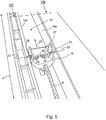
- the fastening end 12 has a form-locking securing on the non-moving area 5, namely here two stub axles or similar holding means 24 which extend in the installed position, namely upwards and downwards, and which before assembly of the tension spring device 14 into lateral recesses 25, in particular holes, the upper and lower channel wall 19a, 19b can engage ( FIG. 5 ) and thereby fix the rear attachment end 12.
- the one or more holding means 24 is or are arranged on spring clip (s) 28, wherein these are movable in the manner of a rocker and thereby the holding means 24 can move inwardly upon pressure on the spring clip 28 and out of engagement with the recesses 25.
- each of these attachment ends 12 with the holding means (s) 24 and the one or more spring clip (s) 28 is formed integrally in one piece.
- the fixed position of the rear attachment end 12 serves to mount the tension spring device 14.
- the end region 6 of the puller 6 is firmly fixed to the stationary region 5 of the dishwasher 1 Dishwasher series always secured the same position and orientation.
- This fuse 23 can be canceled upon connection of the tension spring device 14 with this attachment end 12, so that from then the attachment end 12 is freely movable in the direction of depth 18 in the receiving channel 19.
- the at least one overlapping turn 26 of the tension spring device 14 at the attachment end 12 is positively secured - in particular via a retaining lug 30 - secured.
- the rear attachment end 12 of the traction cable 6 has a securing and / or coupling element. This is used to fix or support the pull rope in an intermediate mounting position to connect the tension spring means 14 during assembly always at the same longitudinal position with the pull cable or to be able to couple.
- the securing and / or coupling element is brought into a release position, so that the fastening end 12 can move freely in the receiving channel 19.
- the release of the securing and / or coupling element for a movement in the axial direction of the receiving channel 19 can preferably be effected by the coupling of the tension spring device itself.
- the tension spring device 14 With the fixation prior to installation of the tension spring device 14 always the same orientation of the attachment end 12, the tension spring device 14 must not be used manually, but can be inserted by a robot in the channel 19. In this case, at the same time a bias of the tension spring 14 be made so that no longer - as before - after assembly, the entire spring device must be laboriously manually clamped to the front attachment end 11 of the hauling rope, in particular a coupling element 11 at the front end of the hawser 6 in bring a parking position on the side hinge plate of the base support 16, in which it can take the pivot lever 13 when mounting the door 3.
- the tension spring 14 relaxes automatically after the solution then attached attachment end 12, so then train on the pivot lever 13 of the door 3 after assembly, in particular without further tensioning measures of the tension spring device and / or the traction cable, can be exercised.
- the attachment end 12 lies with its upper and lower legs 21, 22 approximately parallel to the upper wall 19a and the lower wall 19b of the channel 19, so that only little freedom of movement remains outside the longitudinal movement.
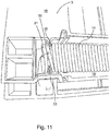
- a rear end portion of the tension spring device 14 engages in this insertion with at least one turn 31, 32 a holding device 33, which is attached to a frame area of the stationary region 5, in particular to a base plate 16 located under the washing container, is integrally formed.
- the tension spring device 14 is automatically set at its rear, remote from the pull rope or end region when inserting, so that when you relax the rear end with the turns 31, 32 is held and only the front end of the attachment end 12 of the traction 6 emotional.
- Holding device saves both components and assembly steps. For example, it can be saved on each page depending on a retaining plate made of metal.
- the holding device 33 may form a partially recessed retaining plate, so that the tension spring device can be inserted directly with its turns 31, 32 in this.
- the tension spring device 14 may already be wound such that a small axial gap remains between the first two windings 31, 32 and the further following turns, into which the holding device 33 can dip.
- the number of turns can vary.
- the holding plate 33 is so far except that a substantially U-shaped, in a channel 19 which receives the tension spring means 14 and also the traction cable 6 substantially, protruding frame 35 remains. This narrows the channel 19, which is here embedded in a base support 19, then only at its edges, so that the middle area remains free.
- the base support 16 is formed according to the drawing together with the holding device 33 as a common plastic injection unit. Both weight and manufacturing costs and durability are favorable in such a solution.
- the tension spring device 14 can be inserted into the channel 19 in a prestressed state in such a way that it is connected at the same time with at least one turn 31, 32 behind the holding device 33 and with at least one foremost turn 26 of its other end with a fastening end 12 of a pull cable 6 while this attachment end 12 then still unlocked, so that it is movable along in the channel 19 during relaxation of the then used tension spring device 14 and thereby train on the pivot lever 13 of the door 3 exerts.
- FIG. 9 In modification to FIG. 9 can in a rear portion of the receiving channel 19, in the end region of a holding plate is pre-mounted as a holding device, which is inserted or pressed into a transverse axial longitudinal extension of the receiving channel 19 receiving gap 40 at the bottom of the receiving channel and its two side walls and pressed and thus an integral part of Base carrier is 16.
- This prefixed retaining plate otherwise performs the same functions as the base support 16 integrally formed holding device 33 according to the embodiment of FIGS. 1 with 11.
- the various components of the invention constructed door weight balance spring system in particular its at least one slider such.
- the receiving channel such as 19, the rear attachment end such as 12 of the pull rope such as 6 provided backup and / or coupling element, the holding device such as 33 in the receiving channel for the end-side fixation of the tension spring device, and / or the tension spring device
- the tension spring device For example, 14, etc .., Expediently designed and arranged relative to each other, that a uniform, ie single mounting preferred direction for all components in their insertion is predetermined in predetermined mounting positions. This simplifies the assembly process for the door weight balance spring system and makes it easier to automate.
- the mounting direction is approximately perpendicular to the respective side wall of the base support, which is arranged below the washing compartment.
- a door weight balance spring system can be conveniently mounted on both sides of the base support, while it passes through a production line for the production of dishwashers.
- the components of the door weight balance spring system are preferably arranged in the respective side wall part or respective side frame part of the base support, that they are substantially positionable or installable in one and the same, ie about the same mounting plane.
- This runs - as here in the embodiments of Figures 1 - 11 - In particular, substantially parallel to the depth direction 18 of the washing container 2.
- the tension spring device and the traction cable in the installed state in the form of a continuous line in series run in series.
Landscapes
- Washing And Drying Of Tableware (AREA)
Priority Applications (1)
| Application Number | Priority Date | Filing Date | Title |
|---|---|---|---|
| PL12167272T PL2524643T3 (pl) | 2011-05-20 | 2012-05-09 | Zmywarka do naczyń z co najmniej jedną jednostką sprężynową do oddziaływania na otwarte drzwi oraz powiązany sposób montażu |
Applications Claiming Priority (1)
| Application Number | Priority Date | Filing Date | Title |
|---|---|---|---|
| DE201110076201 DE102011076201A1 (de) | 2011-05-20 | 2011-05-20 | Geschirrspülmaschine mit zumindest einer Federeinheit zur Beeinflussung einer geöffneten Tür sowie zugehöriges Montageverfahren |
Publications (2)
| Publication Number | Publication Date |
|---|---|
| EP2524643A1 EP2524643A1 (de) | 2012-11-21 |
| EP2524643B1 true EP2524643B1 (de) | 2018-02-07 |
Family
ID=46177304
Family Applications (1)
| Application Number | Title | Priority Date | Filing Date |
|---|---|---|---|
| EP12167272.9A Active EP2524643B1 (de) | 2011-05-20 | 2012-05-09 | Geschirrspülmaschine mit zumindest einer Federeinheit zur Beeinflussung einer geöffneten Tür sowie zugehöriges Montageverfahren |
Country Status (3)
| Country | Link |
|---|---|
| EP (1) | EP2524643B1 (pl) |
| DE (1) | DE102011076201A1 (pl) |
| PL (1) | PL2524643T3 (pl) |
Families Citing this family (3)
| Publication number | Priority date | Publication date | Assignee | Title |
|---|---|---|---|---|
| CN103821420B (zh) * | 2014-02-07 | 2015-12-16 | 广东格兰仕集团有限公司 | 洗碗机的门体平衡调节机构 |
| WO2016086965A1 (en) * | 2014-12-02 | 2016-06-09 | Arcelik Anonim Sirketi | Dishwasher having door-weight compensating apparatus |
| CN107989498B (zh) * | 2017-12-28 | 2024-02-20 | 佛山市顺德区美的洗涤电器制造有限公司 | 家用电器 |
Family Cites Families (4)
| Publication number | Priority date | Publication date | Assignee | Title |
|---|---|---|---|---|
| DE8906198U1 (de) * | 1989-05-19 | 1990-09-27 | Hörmann KG Amshausen, 4803 Steinhagen | Federanschlußglied |
| DE19611052B4 (de) * | 1996-03-20 | 2014-01-16 | BSH Bosch und Siemens Hausgeräte GmbH | Vorrichtung zur Verbindung einer Feder mit einem Gehäuse eines Haushaltgerätes |
| DE19611051B4 (de) * | 1996-03-20 | 2016-06-16 | BSH Hausgeräte GmbH | Haushaltsgerät |
| US7934783B2 (en) * | 2007-05-04 | 2011-05-03 | Electrolux Home Products, Inc. | Counterbalance assembly for a dishwasher door and associated method |
-
2011
- 2011-05-20 DE DE201110076201 patent/DE102011076201A1/de not_active Withdrawn
-
2012
- 2012-05-09 EP EP12167272.9A patent/EP2524643B1/de active Active
- 2012-05-09 PL PL12167272T patent/PL2524643T3/pl unknown
Non-Patent Citations (1)
| Title |
|---|
| None * |
Also Published As
| Publication number | Publication date |
|---|---|
| EP2524643A1 (de) | 2012-11-21 |
| PL2524643T3 (pl) | 2018-07-31 |
| DE102011076201A1 (de) | 2012-11-22 |
Similar Documents
| Publication | Publication Date | Title |
|---|---|---|
| EP2526848B1 (de) | Geschirrspülmaschine mit zumindest einer Federeinheit zur Beeinflussung einer geöffneten Tür | |
| EP3585211B1 (de) | Anordnung mit möbelteile und verbindungsstift | |
| EP0956416B1 (de) | Vorrichtung zur befestigung einer verschiebbaren fensterscheibe eines kraftfahrzeugs an der führungsvorrichtung eines fensterhebers | |
| EP2734691B1 (de) | Schloss für eine fahrzeugtür mit federblech im einlaufbereich des schliessbolzens | |
| EP3417132B1 (de) | Türfeststeller | |
| EP3126685B1 (de) | Verbinder, verbindungsverfahren sowie herstellungsverfahren dafür | |
| EP3535822B1 (de) | Schaltschrank mit einer montageplattenanordnung | |
| EP2524643B1 (de) | Geschirrspülmaschine mit zumindest einer Federeinheit zur Beeinflussung einer geöffneten Tür sowie zugehöriges Montageverfahren | |
| EP1442243B1 (de) | Halter für einen körper und befestigungsanordnung mit einem derartigen halter | |
| WO2013087375A1 (de) | Befestigungselement und seitengitter | |
| DE102006029396A1 (de) | Befestigungssystem für Solarmodule | |
| DE102011076205A1 (de) | Geschirrspülmaschine mit zumindest einer Federeinheit zur Beeinflussung einer geöffneten Tür | |
| EP2815051B1 (de) | Lageranordnung für eine verstellvorrichtung eines kraftfahrzeugs | |
| DE102011013138B3 (de) | Vorrichtung zum Einsetzen eines Kämpfers in einen Tür- oder Fensterrahmen | |
| WO2014180457A1 (de) | Befestigungselement zur anbindung von übertragungsmitteln an ein hebelelement | |
| DE102011076207A1 (de) | Montage einer Geschirrspülmaschine mit zumindest einer Federeinheit zur Beeinflussung einer geöffneten Tür | |
| DE102012101338B4 (de) | Wischerblatt-Montagewinkel | |
| EP3665038B1 (de) | Längseinsteller für einen fahrzeugsitz | |
| DE102011076202A1 (de) | Geschirrspülmaschine mit zumindest einer Federeinheit zur Beeinflussung einer geöffneten Tür | |
| AT527376B1 (de) | Schubladenseitenwand für eine Schublade | |
| EP1666736B1 (de) | Halteclip für Kraftfahrzeugkarosserien | |
| AT527377B1 (de) | Schubladenseitenwand für eine Schublade | |
| WO2013064256A1 (de) | Bahngesteuerte verstellvorrichtung mit einer mehrteiligen trägerbaugruppe | |
| DE102012214423B4 (de) | Geschirrspülmaschine mit einem über eine Gelenkanordnung schwenkbaren Türelement | |
| EP3771365B1 (de) | Vorhangschienenanordnung |
Legal Events
| Date | Code | Title | Description |
|---|---|---|---|
| PUAI | Public reference made under article 153(3) epc to a published international application that has entered the european phase |
Free format text: ORIGINAL CODE: 0009012 |
|
| AK | Designated contracting states |
Kind code of ref document: A1 Designated state(s): AL AT BE BG CH CY CZ DE DK EE ES FI FR GB GR HR HU IE IS IT LI LT LU LV MC MK MT NL NO PL PT RO RS SE SI SK SM TR |
|
| AX | Request for extension of the european patent |
Extension state: BA ME |
|
| 17P | Request for examination filed |
Effective date: 20130521 |
|
| RAP1 | Party data changed (applicant data changed or rights of an application transferred) |
Owner name: BSH HAUSGERAETE GMBH |
|
| 17Q | First examination report despatched |
Effective date: 20170517 |
|
| GRAP | Despatch of communication of intention to grant a patent |
Free format text: ORIGINAL CODE: EPIDOSNIGR1 |
|
| INTG | Intention to grant announced |
Effective date: 20171017 |
|
| GRAS | Grant fee paid |
Free format text: ORIGINAL CODE: EPIDOSNIGR3 |
|
| GRAA | (expected) grant |
Free format text: ORIGINAL CODE: 0009210 |
|
| AK | Designated contracting states |
Kind code of ref document: B1 Designated state(s): AL AT BE BG CH CY CZ DE DK EE ES FI FR GB GR HR HU IE IS IT LI LT LU LV MC MK MT NL NO PL PT RO RS SE SI SK SM TR |
|
| REG | Reference to a national code |
Ref country code: GB Ref legal event code: FG4D Free format text: NOT ENGLISH |
|
| REG | Reference to a national code |
Ref country code: AT Ref legal event code: REF Ref document number: 968471 Country of ref document: AT Kind code of ref document: T Effective date: 20180215 Ref country code: CH Ref legal event code: EP |
|
| REG | Reference to a national code |
Ref country code: IE Ref legal event code: FG4D Free format text: LANGUAGE OF EP DOCUMENT: GERMAN |
|
| REG | Reference to a national code |
Ref country code: DE Ref legal event code: R096 Ref document number: 502012012114 Country of ref document: DE |
|
| REG | Reference to a national code |
Ref country code: NL Ref legal event code: MP Effective date: 20180207 |
|
| PG25 | Lapsed in a contracting state [announced via postgrant information from national office to epo] |
Ref country code: HR Free format text: LAPSE BECAUSE OF FAILURE TO SUBMIT A TRANSLATION OF THE DESCRIPTION OR TO PAY THE FEE WITHIN THE PRESCRIBED TIME-LIMIT Effective date: 20180207 Ref country code: NL Free format text: LAPSE BECAUSE OF FAILURE TO SUBMIT A TRANSLATION OF THE DESCRIPTION OR TO PAY THE FEE WITHIN THE PRESCRIBED TIME-LIMIT Effective date: 20180207 Ref country code: LT Free format text: LAPSE BECAUSE OF FAILURE TO SUBMIT A TRANSLATION OF THE DESCRIPTION OR TO PAY THE FEE WITHIN THE PRESCRIBED TIME-LIMIT Effective date: 20180207 Ref country code: ES Free format text: LAPSE BECAUSE OF FAILURE TO SUBMIT A TRANSLATION OF THE DESCRIPTION OR TO PAY THE FEE WITHIN THE PRESCRIBED TIME-LIMIT Effective date: 20180207 Ref country code: FI Free format text: LAPSE BECAUSE OF FAILURE TO SUBMIT A TRANSLATION OF THE DESCRIPTION OR TO PAY THE FEE WITHIN THE PRESCRIBED TIME-LIMIT Effective date: 20180207 Ref country code: NO Free format text: LAPSE BECAUSE OF FAILURE TO SUBMIT A TRANSLATION OF THE DESCRIPTION OR TO PAY THE FEE WITHIN THE PRESCRIBED TIME-LIMIT Effective date: 20180507 Ref country code: CY Free format text: LAPSE BECAUSE OF FAILURE TO SUBMIT A TRANSLATION OF THE DESCRIPTION OR TO PAY THE FEE WITHIN THE PRESCRIBED TIME-LIMIT Effective date: 20180207 |
|
| PG25 | Lapsed in a contracting state [announced via postgrant information from national office to epo] |
Ref country code: GR Free format text: LAPSE BECAUSE OF FAILURE TO SUBMIT A TRANSLATION OF THE DESCRIPTION OR TO PAY THE FEE WITHIN THE PRESCRIBED TIME-LIMIT Effective date: 20180508 Ref country code: IS Free format text: LAPSE BECAUSE OF FAILURE TO SUBMIT A TRANSLATION OF THE DESCRIPTION OR TO PAY THE FEE WITHIN THE PRESCRIBED TIME-LIMIT Effective date: 20180607 Ref country code: SE Free format text: LAPSE BECAUSE OF FAILURE TO SUBMIT A TRANSLATION OF THE DESCRIPTION OR TO PAY THE FEE WITHIN THE PRESCRIBED TIME-LIMIT Effective date: 20180207 Ref country code: LV Free format text: LAPSE BECAUSE OF FAILURE TO SUBMIT A TRANSLATION OF THE DESCRIPTION OR TO PAY THE FEE WITHIN THE PRESCRIBED TIME-LIMIT Effective date: 20180207 Ref country code: BG Free format text: LAPSE BECAUSE OF FAILURE TO SUBMIT A TRANSLATION OF THE DESCRIPTION OR TO PAY THE FEE WITHIN THE PRESCRIBED TIME-LIMIT Effective date: 20180507 Ref country code: RS Free format text: LAPSE BECAUSE OF FAILURE TO SUBMIT A TRANSLATION OF THE DESCRIPTION OR TO PAY THE FEE WITHIN THE PRESCRIBED TIME-LIMIT Effective date: 20180207 |
|
| PG25 | Lapsed in a contracting state [announced via postgrant information from national office to epo] |
Ref country code: MT Free format text: LAPSE BECAUSE OF FAILURE TO SUBMIT A TRANSLATION OF THE DESCRIPTION OR TO PAY THE FEE WITHIN THE PRESCRIBED TIME-LIMIT Effective date: 20180207 |
|
| PG25 | Lapsed in a contracting state [announced via postgrant information from national office to epo] |
Ref country code: RO Free format text: LAPSE BECAUSE OF FAILURE TO SUBMIT A TRANSLATION OF THE DESCRIPTION OR TO PAY THE FEE WITHIN THE PRESCRIBED TIME-LIMIT Effective date: 20180207 Ref country code: IT Free format text: LAPSE BECAUSE OF FAILURE TO SUBMIT A TRANSLATION OF THE DESCRIPTION OR TO PAY THE FEE WITHIN THE PRESCRIBED TIME-LIMIT Effective date: 20180207 Ref country code: AL Free format text: LAPSE BECAUSE OF FAILURE TO SUBMIT A TRANSLATION OF THE DESCRIPTION OR TO PAY THE FEE WITHIN THE PRESCRIBED TIME-LIMIT Effective date: 20180207 Ref country code: EE Free format text: LAPSE BECAUSE OF FAILURE TO SUBMIT A TRANSLATION OF THE DESCRIPTION OR TO PAY THE FEE WITHIN THE PRESCRIBED TIME-LIMIT Effective date: 20180207 |
|
| REG | Reference to a national code |
Ref country code: DE Ref legal event code: R097 Ref document number: 502012012114 Country of ref document: DE |
|
| PG25 | Lapsed in a contracting state [announced via postgrant information from national office to epo] |
Ref country code: SM Free format text: LAPSE BECAUSE OF FAILURE TO SUBMIT A TRANSLATION OF THE DESCRIPTION OR TO PAY THE FEE WITHIN THE PRESCRIBED TIME-LIMIT Effective date: 20180207 Ref country code: DK Free format text: LAPSE BECAUSE OF FAILURE TO SUBMIT A TRANSLATION OF THE DESCRIPTION OR TO PAY THE FEE WITHIN THE PRESCRIBED TIME-LIMIT Effective date: 20180207 Ref country code: CZ Free format text: LAPSE BECAUSE OF FAILURE TO SUBMIT A TRANSLATION OF THE DESCRIPTION OR TO PAY THE FEE WITHIN THE PRESCRIBED TIME-LIMIT Effective date: 20180207 Ref country code: SK Free format text: LAPSE BECAUSE OF FAILURE TO SUBMIT A TRANSLATION OF THE DESCRIPTION OR TO PAY THE FEE WITHIN THE PRESCRIBED TIME-LIMIT Effective date: 20180207 |
|
| PLBE | No opposition filed within time limit |
Free format text: ORIGINAL CODE: 0009261 |
|
| REG | Reference to a national code |
Ref country code: CH Ref legal event code: PL |
|
| STAA | Information on the status of an ep patent application or granted ep patent |
Free format text: STATUS: NO OPPOSITION FILED WITHIN TIME LIMIT |
|
| 26N | No opposition filed |
Effective date: 20181108 |
|
| GBPC | Gb: european patent ceased through non-payment of renewal fee |
Effective date: 20180509 |
|
| REG | Reference to a national code |
Ref country code: BE Ref legal event code: MM Effective date: 20180531 |
|
| PG25 | Lapsed in a contracting state [announced via postgrant information from national office to epo] |
Ref country code: MC Free format text: LAPSE BECAUSE OF FAILURE TO SUBMIT A TRANSLATION OF THE DESCRIPTION OR TO PAY THE FEE WITHIN THE PRESCRIBED TIME-LIMIT Effective date: 20180207 |
|
| REG | Reference to a national code |
Ref country code: IE Ref legal event code: MM4A |
|
| PG25 | Lapsed in a contracting state [announced via postgrant information from national office to epo] |
Ref country code: CH Free format text: LAPSE BECAUSE OF NON-PAYMENT OF DUE FEES Effective date: 20180531 Ref country code: LI Free format text: LAPSE BECAUSE OF NON-PAYMENT OF DUE FEES Effective date: 20180531 Ref country code: SI Free format text: LAPSE BECAUSE OF FAILURE TO SUBMIT A TRANSLATION OF THE DESCRIPTION OR TO PAY THE FEE WITHIN THE PRESCRIBED TIME-LIMIT Effective date: 20180207 |
|
| PG25 | Lapsed in a contracting state [announced via postgrant information from national office to epo] |
Ref country code: LU Free format text: LAPSE BECAUSE OF NON-PAYMENT OF DUE FEES Effective date: 20180509 |
|
| PG25 | Lapsed in a contracting state [announced via postgrant information from national office to epo] |
Ref country code: FR Free format text: LAPSE BECAUSE OF NON-PAYMENT OF DUE FEES Effective date: 20180531 Ref country code: IE Free format text: LAPSE BECAUSE OF NON-PAYMENT OF DUE FEES Effective date: 20180509 Ref country code: GB Free format text: LAPSE BECAUSE OF NON-PAYMENT OF DUE FEES Effective date: 20180509 |
|
| PG25 | Lapsed in a contracting state [announced via postgrant information from national office to epo] |
Ref country code: BE Free format text: LAPSE BECAUSE OF NON-PAYMENT OF DUE FEES Effective date: 20180531 |
|
| REG | Reference to a national code |
Ref country code: AT Ref legal event code: MM01 Ref document number: 968471 Country of ref document: AT Kind code of ref document: T Effective date: 20180509 |
|
| PG25 | Lapsed in a contracting state [announced via postgrant information from national office to epo] |
Ref country code: AT Free format text: LAPSE BECAUSE OF NON-PAYMENT OF DUE FEES Effective date: 20180509 |
|
| PG25 | Lapsed in a contracting state [announced via postgrant information from national office to epo] |
Ref country code: PT Free format text: LAPSE BECAUSE OF FAILURE TO SUBMIT A TRANSLATION OF THE DESCRIPTION OR TO PAY THE FEE WITHIN THE PRESCRIBED TIME-LIMIT Effective date: 20180207 Ref country code: HU Free format text: LAPSE BECAUSE OF FAILURE TO SUBMIT A TRANSLATION OF THE DESCRIPTION OR TO PAY THE FEE WITHIN THE PRESCRIBED TIME-LIMIT; INVALID AB INITIO Effective date: 20120509 |
|
| PG25 | Lapsed in a contracting state [announced via postgrant information from national office to epo] |
Ref country code: MK Free format text: LAPSE BECAUSE OF NON-PAYMENT OF DUE FEES Effective date: 20180207 |
|
| REG | Reference to a national code |
Ref country code: DE Ref legal event code: R084 Ref document number: 502012012114 Country of ref document: DE |
|
| PGFP | Annual fee paid to national office [announced via postgrant information from national office to epo] |
Ref country code: PL Payment date: 20250425 Year of fee payment: 14 Ref country code: DE Payment date: 20250531 Year of fee payment: 14 |
|
| PGFP | Annual fee paid to national office [announced via postgrant information from national office to epo] |
Ref country code: TR Payment date: 20250505 Year of fee payment: 14 |