EP2522858A2 - Radiallüfterrad und Haushaltsgerät mit einem Radiallüfterrad - Google Patents
Radiallüfterrad und Haushaltsgerät mit einem Radiallüfterrad Download PDFInfo
- Publication number
- EP2522858A2 EP2522858A2 EP12166751A EP12166751A EP2522858A2 EP 2522858 A2 EP2522858 A2 EP 2522858A2 EP 12166751 A EP12166751 A EP 12166751A EP 12166751 A EP12166751 A EP 12166751A EP 2522858 A2 EP2522858 A2 EP 2522858A2
- Authority
- EP
- European Patent Office
- Prior art keywords
- radial fan
- fan according
- partition plate
- additional
- collar
- Prior art date
- Legal status (The legal status is an assumption and is not a legal conclusion. Google has not performed a legal analysis and makes no representation as to the accuracy of the status listed.)
- Granted
Links
Images
Classifications
-
- F—MECHANICAL ENGINEERING; LIGHTING; HEATING; WEAPONS; BLASTING
- F04—POSITIVE - DISPLACEMENT MACHINES FOR LIQUIDS; PUMPS FOR LIQUIDS OR ELASTIC FLUIDS
- F04D—NON-POSITIVE-DISPLACEMENT PUMPS
- F04D17/00—Radial-flow pumps, e.g. centrifugal pumps; Helico-centrifugal pumps
- F04D17/08—Centrifugal pumps
- F04D17/16—Centrifugal pumps for displacing without appreciable compression
- F04D17/162—Double suction pumps
-
- F—MECHANICAL ENGINEERING; LIGHTING; HEATING; WEAPONS; BLASTING
- F04—POSITIVE - DISPLACEMENT MACHINES FOR LIQUIDS; PUMPS FOR LIQUIDS OR ELASTIC FLUIDS
- F04D—NON-POSITIVE-DISPLACEMENT PUMPS
- F04D17/00—Radial-flow pumps, e.g. centrifugal pumps; Helico-centrifugal pumps
- F04D17/02—Radial-flow pumps, e.g. centrifugal pumps; Helico-centrifugal pumps having non-centrifugal stages, e.g. centripetal
- F04D17/025—Radial-flow pumps, e.g. centrifugal pumps; Helico-centrifugal pumps having non-centrifugal stages, e.g. centripetal comprising axial flow and radial flow stages
-
- F—MECHANICAL ENGINEERING; LIGHTING; HEATING; WEAPONS; BLASTING
- F04—POSITIVE - DISPLACEMENT MACHINES FOR LIQUIDS; PUMPS FOR LIQUIDS OR ELASTIC FLUIDS
- F04D—NON-POSITIVE-DISPLACEMENT PUMPS
- F04D29/00—Details, component parts, or accessories
- F04D29/26—Rotors specially for elastic fluids
- F04D29/28—Rotors specially for elastic fluids for centrifugal or helico-centrifugal pumps for radial-flow or helico-centrifugal pumps
- F04D29/281—Rotors specially for elastic fluids for centrifugal or helico-centrifugal pumps for radial-flow or helico-centrifugal pumps for fans or blowers
-
- F—MECHANICAL ENGINEERING; LIGHTING; HEATING; WEAPONS; BLASTING
- F04—POSITIVE - DISPLACEMENT MACHINES FOR LIQUIDS; PUMPS FOR LIQUIDS OR ELASTIC FLUIDS
- F04D—NON-POSITIVE-DISPLACEMENT PUMPS
- F04D29/00—Details, component parts, or accessories
- F04D29/26—Rotors specially for elastic fluids
- F04D29/28—Rotors specially for elastic fluids for centrifugal or helico-centrifugal pumps for radial-flow or helico-centrifugal pumps
- F04D29/30—Vanes
-
- F—MECHANICAL ENGINEERING; LIGHTING; HEATING; WEAPONS; BLASTING
- F24—HEATING; RANGES; VENTILATING
- F24C—DOMESTIC STOVES OR RANGES ; DETAILS OF DOMESTIC STOVES OR RANGES, OF GENERAL APPLICATION
- F24C15/00—Details
- F24C15/20—Removing cooking fumes
- F24C15/2007—Removing cooking fumes from oven cavities
Definitions
- the present invention relates to a radial fan according to the preamble of patent claim 1 and a domestic appliance according to the preamble of claim 9.
- a cooking appliance in this case has a blower unit which comprises at least one motor arranged in an engine compartment. At least one fan arranged in the cooking space can be driven by means of a drive shaft guided through a dividing wall.
- the blower unit has an additional delivery unit for generating a gas pressure sealing the engine compartment against vapor.
- the invention has for its object to improve the radial fan from the prior art in its mode of action.
- the additional delivery unit on air blades.
- the air blades of the additional delivery unit cause an improved delivery rate, which is also well controlled by the geometric design of the air blades.
- the entire volume of air sucked in by the additional delivery unit is preferably conveyed radially outwards via the main delivery unit.
- the air blades of the additional delivery unit generate an air flow along an axis of rotation of the fan wheel.
- the additional delivery unit is thus designed according to an axial fan.
- a blow-out region of the additional delivery unit opens in the intake region of the main delivery unit.
- the air blades of the additional delivery unit are at least partially disposed in an opening of the partition plate. This allows a particularly flat design of the radial fan especially in particular, if the additional feed unit does not project, or only slightly beyond the partition plate. Over the cross section of the opening, an air flow rate of the additional delivery unit is controllable.
- the collar is arranged on the partition plate. This allows a compact design and also favors the formation of the radial fan as a plastic injection molded part.
- the additional delivery unit is arranged within an opening bounded by the collar. This creates a defined, clearly delimited flow channel of the additional delivery unit. This flow channel can be easily coupled to adjacent flow channels with sufficient tightness.
- the collar has a height of 2 to 10 mm, preferably from 3 to 8 mm. This allows a compact design of the radial fan and also ensures sufficient coverage in the event of immersion of the collar in an adjacent air duct. This overlap or overlap causes a seal and largely prevents the intake of false air.
- the air blades of the auxiliary conveyor unit form a mechanical connection between a arranged along the central axis drive axle receiving and the partition plate, a material saving in the production of the radial fan is enabled.
- the air blades form the sole mechanical connection between the drive axle receiving and the separating plate.
- the air blades are arranged in two superimposed planes, whereby the air flow is increased again. In addition, this allows a more stable connection of the drive axle receptacle to the partition plate.
- the invention relates to a household appliance with a radial fan according to the invention, wherein the collar dips into an intake duct.
- a particularly dense interface can be achieved.
- the partition plate of the radial fan has production due to a certain delay, or a certain flatness tolerance. This makes it necessary to maintain a certain minimum distance of the partition plate from, for example, a surface surrounding a suction hole of the household appliance. However, this required minimum distance causes a false air suction through a gap, which results between the surface surrounding the suction hole and the partition plate.
- a collar which dips into the suction hole, or in the intake passage, such suction of false air is prevented.
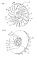
- the radial fan in FIG. 1 has a partition plate 2, in the center of a drive axle receiving 4 is arranged. This is sleeve-shaped and serves to receive a motor axis of a fan motor (not shown). For receiving the motor shaft, the drive axle receiving 4 has a receiving opening 5, in which the motor shaft (not shown) is inserted.
- the drive axle receiving 4 is connected via four retaining webs 6 with the partition plate 2.
- a main conveyor unit 8 is arranged in the form of air blades 10.
- the air blades 10 of the main conveyor unit 8 extend from an outer periphery of the partition plate 2 radially inwardly in the direction of the drive axle receiving 4.
- the air blades 10 of the main conveyor unit 8 are arcuately formed and have a height H.
- the air blades 10 terminate in front of a circular opening 11, which is arranged in the middle of the partition plate 2 is and in the center of the drive axle receiving 4 forms.
- the opening 11 has an additional delivery unit 12, which is formed by four air blades 14.
- the air blades 14 are designed such that they cause an air flow in the direction of an axis 18.
- the axis 18 forms the axis of rotation of the drive axle, or the entire radial fan.
- FIG. 2 shows a formed on a bottom of the radial fan collar 16, whose inner diameter corresponds to the diameter of the opening 11.
- the air blades 14 of the additional conveying unit 12 are arranged within the collar 16. In addition, they are each arranged centrally along an angle bisector in spaces 17 formed by the retaining webs 6. According to the stability requirements, it is also possible in an alternative embodiment (not shown) to form the retaining webs 6 likewise in the form of air blades 14.
- the additional delivery unit 12 is composed of two rows of air blades 14, which are arranged with respect to the axis 18 in the axial direction spaced from each other.
- the two rows of air blades 14 are arranged offset from one another in such a way that the resulting gaps between the air blades 14 are the same size.
- the air blades 14 of the auxiliary conveyor unit 12 are inclined in both embodiments in the direction of the axis 18 so that they cause an air flow along the axis 18.
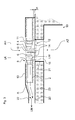
- the representation in FIG. 3 schematically shows the built-in cooking appliance radial fan.
- the radial fan serves to generate a cooling air flow LK, which is used for cooling a switch room of the cooking appliance (not shown).
- the radial fan causes through its additional delivery unit 12 a removal of a Wrasens from a, surrounded by an insulation 23 oven muffle 19 of the cooking appliance.
- the discharged vapor is mixed with the cooling air flow LK.
- the cooling air flow LK which is conveyed radially outward into a blow-out region A via the main conveying unit 8, is formed by means of an intake region AH of the main delivery unit 8 arranged at the top.
- the circular suction area AH of the main conveyor unit 8 is arranged centrally above the main conveyor unit 8.
- the axis 18 forms the center of the intake AH.
- a compressed air flow LW is additionally drawn in via an intake area AZ of the additional delivery unit 12.
- the compressed air flow LW is conveyed by means of the air blades 14 of the additional delivery unit 12 to the main delivery unit 8 arranged above the separating plate 2.
- the Wrasen Kunststoffstrom LW from the intake AZ of the additional delivery unit 12 and the cooling air flow LK result in a mixed air flow LM, which is conveyed via the blow-out A in a blow-out 22.
- a gap S between the partition plate 2 and a cover plate 20 arranged on the insulation 23 can be chosen generously, since the collar 16 is designed such that it dips into the intake passage 21 and thereby largely prevents the intake of a faulty air via the gap S.
Landscapes
- Engineering & Computer Science (AREA)
- Mechanical Engineering (AREA)
- General Engineering & Computer Science (AREA)
- Chemical & Material Sciences (AREA)
- Combustion & Propulsion (AREA)
- Structures Of Non-Positive Displacement Pumps (AREA)
Abstract
Description
- Die vorliegende Erfindung betrifft ein Radiallüfterrad gemäß dem Oberbegriff des Patentanspruchs 1 und ein Haushaltsgerät gemäß dem Oberbegriff des Patentanspruchs 9.
- Ein derartiges Radiallüfterrad ist bekannt aus der Druckschrift
EP 1 306 623 B1 . Ein Gargerät weist dabei eine Gebläseeinheit auf, die zumindest einen in einem Motorraum angeordneten Motor umfasst. Über diesen ist mit einer durch eine Trennwand geführte Antriebswelle zumindest ein im Garraum angeordneter Lüfter antreibbar. Dabei weist die Gebläseeinheit eine Zusatzfördereinheit zur Erzeugung eines den Motorraum gegen Wrasen abdichtenden Gasdrucks auf. - Der Erfindung liegt die Aufgabe zugrunde, das Radiallüfterrad aus dem Stand der Technik in seiner Wirkungsweise zu verbessern.
- Diese Aufgabe wird durch ein Radiallüfterrad mit den Merkmalen des Patentanspruchs 1, sowie durch ein Haushaltsgerät mit den Merkmalen des Patentanspruchs 9 gelöst.
- Gemäß dem kennzeichnenden Teil des Patentanspruchs 1 weist die Zusatzfördereinheit Luftschaufeln auf. Die Luftschaufeln der Zusatzfördereinheit bewirken eine verbesserte Förderleistung, die durch die geometrische Auslegung der Luftschaufeln zudem gut steuerbar ist. Dabei wird bevorzugt das gesamte, von der Zusatzfördereinheit angesaugte Luftvolumen über die Hauptfördereinheit radial nach außen gefördert.
- Bei einer bevorzugten Ausgestaltung erzeugen die Luftschaufeln der Zusatzfördereinheit einen Luftstrom entlang einer Drehachse des Lüfterrades. Die Zusatzfördereinheit ist somit entsprechend einem Axiallüfterrad ausgebildet. Dabei mündet ein Ausblasbereich der Zusatzfördereinheit im Ansaugbereich der Hauptfördereinheit.
- In einer weiteren Ausgestaltung wird vorgeschlagen, dass die Luftschaufeln der Zusatzfördereinheit zumindest teilweise in einer Öffnung der Trennplatte angeordnet sind. Dies ermöglicht eine besonders flache Ausbildung des Radiallüfterrades insbesondere dann, wenn die Zusatzfördereinheit nicht, oder nur geringfügig über die Trennplatte hinausragt. Über den Querschnitt der Öffnung ist ein Luftdurchsatz der Zusatzfördereinheit steuerbar.
- Ist die Zusatzfördereinheit von einem ringförmigen Kragen umgeben, so ist dadurch aufgrund der versteifenden Wirkung des Kragens ein stabiles Radiallüfterrad geschaffen, das schwingungsarme Laufeigenschaften aufweist.
- Vorzugsweise ist der Kragen auf der Trennplatte angeordnet. Dies ermöglicht eine kompakte Bauweise und begünstigt zudem die Ausbildung des Radiallüfterrades als Kunststoffspritzgußteil.
- Bevorzugt ist es, wenn die Zusatzfördereinheit innerhalb einer vom Kragen eingegrenzten Öffnung angeordnet ist. Dadurch wird ein definierter, klar abgegrenzter Strömungskanal der Zusatzfördereinheit geschaffen. Dieser Strömungskanal ist mit hinreichender Dichtigkeit einfach an angrenzende Strömungskanäle ankoppelbar.
- In einer vorteilhaften Ausgestaltung der Erfindung weist der Kragen eine Höhe von 2 bis 10 mm, bevorzugt von 3 bis 8 mm auf. Dadurch ist eine kompakte Bauweise des Radiallüfterrades ermöglicht und zudem im Falle eines Eintauchens des Kragens in einen angrenzenden Luftkanal eine ausreichende Überdeckung gewährleistet. Diese Überdeckung bzw. Überlappung bewirkt eine Abdichtung und verhindert weitestgehend das Ansaugen von Fehlluft.
- Indem die Luftschaufeln der Zusatzfördereinheit eine mechanische Verbindung zwischen einer entlang der Mittelachse angeordneten Antriebsachsenaufnahme und der Trennplatte bilden, ist eine Materialeinsparung bei der Herstellung des Radiallüfterrades ermöglicht. Bevorzugt bilden die Luftschaufeln die alleinige mechanische Verbindung zwischen der Antriebsachsenaufnahme und der Trennplatte. In einer vorteilhaften Weiterbildung sind die Luftschaufeln dabei in zwei übereinanderliegenden Ebenen angeordnet, wodurch der Luftdurchsatz nochmals gesteigert wird. Zudem ist dadurch eine stabilere Anbindung der Antriebsachsenaufnahme an die Trennplatte ermöglicht.
- Des Weiteren betrifft die Erfindung ein Haushaltsgerät mit einem erfindungsgemäßen Radiallüfterrad, wobei dessen Kragen in einen Ansaugkanal eintaucht. Durch eine derartige Ankopplung zwischen Radiallüfterrad und dem Ansaugkanal des Haushaltsgerätes kann eine besonders dichte Schnittstelle erreicht werden. Die Trennplatte des Radiallüfterrades weist herstellungsbedingt einen gewissen Verzug, bzw. eine bestimmte Ebenheitstoleranz auf. Dadurch ist es erforderlich, einen gewissen Mindestabstand der Trennplatte gegenüber beispielsweise einer Fläche, die ein Ansaugloch des Haushaltsgerätes umgibt, einzuhalten. Dieser erforderliche Mindestabstand bewirkt jedoch ein Ansaugen von Fehlluft durch einen Spalt, der sich zwischen der das Ansaugloch umgebenden Fläche und der Trennplatte ergibt. Durch die Ausbildung eines Kragens, der in das Ansaugloch, bzw. in den Ansaugkanal eintaucht, wird ein derartiges Ansaugen von Fehlluft verhindert.
- Weitere Merkmale und Vorteile der Erfindung ergeben sich aus der nachfolgenden Beschreibung eines Ausführungsbeispiels unter Bezugnahme auf die beigefügten Figuren.
- Es zeigen:
- Figur 1
- das erfindungsgemäße Radiallüfterrad in einer räumlichen Darstellung von oben;
- Figur 2
- das Radiallüfterrad in einer räumlichen Darstellung von unten und
- Figur 3
- eine Prinzipdarstellung des in ein Gargerät eingebauten Radiallüfterrades.
- Das Radiallüfterrad in
Figur 1 weist eine Trennplatte 2 auf, in dessen Zentrum eine Antriebsachsenaufnahme 4 angeordnet ist. Diese ist hülsenförmig ausgebildet und dient zur Aufnahme einer Motorachse eines Lüftermotors (nicht gezeigt). Zur Aufnahme der Motorachse weist die Antriebsachsenaufnahme 4 eine Aufnahmeöffnung 5 auf, in die die Motorachse (nicht gezeigt) gesteckt ist. Die Antriebsachsenaufnahme 4 ist über vier Haltestege 6 mit der Trennplatte 2 verbunden. Auf der Trennplatte 2 ist eine Hauptfördereinheit 8 in Form von Luftschaufeln 10 angeordnet. Die Luftschaufeln 10 der Hauptfördereinheit 8 erstrecken sich dabei von einem Außenumfang der Trennplatte 2 radial nach innen in Richtung der Antriebsachsenaufnahme 4. Die Luftschaufeln 10 der Hauptfördereinheit 8 sind dabei bogenförmig ausgebildet und weisen eine Höhe H auf. Die Luftschaufeln 10 enden vor einer kreisförmigen Öffnung 11, die in der Mitte der Trennplatte 2 angeordnet ist und in dessen Zentrum die Antriebsachsenaufnahme 4 bildet. Die Öffnung 11 weist eine Zusatzfördereinheit 12 auf, die durch vier Luftschaufeln 14 gebildet wird. Die Luftschaufeln 14 sind dabei derart ausgestaltet, dass sie einen Luftstrom in Richtung einer Achse 18 bewirken. Die Achse 18 bildet dabei die Rotationsachse der Antriebsachsenaufnahme, bzw. des gesamten Radiallüfterrades. -
Figur 2 zeigt einen an einer Unterseite des Radiallüfterrades ausgebildeten Kragen 16, dessen Innendurchmesser dem Durchmesser der Öffnung 11 entspricht. Die Luftschaufeln 14 der Zusatzfördereinheit 12 sind dabei innerhalb des Kragens 16 angeordnet. Zudem sind sie jeweils mittig entlang einer Winkelhalbierenden in von den Haltestegen 6 gebildeten Zwischenräumen 17 angeordnet. Entsprechend den Anforderungen an die Stabilität ist es in einer alternativen Ausgestaltung (nicht gezeigt) auch möglich, die Haltestege 6 ebenfalls in Form von Luftschaufeln 14 auszubilden. Damit setzt sich die Zusatzfördereinheit 12 aus zwei Reihen von Luftschaufeln 14 zusammen, die bezüglich der Achse 18 in Achsrichtung beabstandet voneinander angeordnet sind. Bei einer Blickrichtung in Richtung der Achse 18 sind die beiden Reihen an Luftschaufeln 14 dabei derart zueinander versetzt angeordnet, dass die sich ergebenden Lücken zwischen den Luftschaufeln 14 gleich groß sind. Die Luftschaufeln 14 der Zusatzfördereinheit 12 sind dabei in beiden Ausgestaltungen derart in Richtung der Achse 18 geneigt, dass sie einen Luftstrom entlang der Achse 18 bewirken. - Die Darstellung in
Figur 3 zeigt schematisch das in ein Gargerät eingebaute Radiallüfterrad. Das Radiallüfterrad dient dabei zur Erzeugung eines Kühlluftstromes LK, der zur Kühlung eines Schalterraumes des Gargerätes (nicht gezeigt) verwendet wird. Zudem bewirkt das Radiallüfterrad durch seine Zusatzfördereinheit 12 eine Abfuhr eines Wrasens aus einer, mit einer Isolierung 23 umgebenen Backofenmuffel 19 des Gargerätes. Der abgeführte Wrasen wird dabei mit dem Kühlluftstrom LK vermischt. Über einen oben angeordneten Ansaugbereich AH der Hauptfördereinheit 8 bildet sich im Betrieb der Kühlluftstrom LK aus, der über die Hauptfördereinheit 8 radial nach außen in einen Ausblasbereich A gefördert wird. Der kreisförmige ausgebildete Ansaugbereich AH der Hauptfördereinheit 8 ist dabei mittig oberhalb der Hauptfördereinheit 8 angeordnet. Die Achse 18 bildet dabei das Zentrum des Ansaugbereiches AH. Über einen Ansaugkanal 21 wird gegenüberliegend zum Ansaugbereich AH der Hauptfördereinheit 8 zusätzlich über einen Ansaugbereich AZ der Zusatzfördereinheit 12 ein Wrasenluftstrom LW angesaugt. Durch die Öffnung 11 wird der Wrasenluftstrom LW mittels der Luftschaufeln 14 der Zusatzfördereinheit 12 zur oberhalb der Trennplatte 2 angeordneten Hauptfördereinheit 8 gefördert. Der Wrasenluftstrom LW aus dem Ansaugbereich AZ der Zusatzfördereinheit 12 und der Kühlluftstrom LK ergeben dabei einen Mischluftstrom LM, der über den Ausblasbereich A in einen Ausblaskanal 22 gefördert wird. Ein Spalt S zwischen der Trennplatte 2 und einem auf der Isolierung 23 angeordneten Abdeckblech 20 kann dabei großzügig gewählt werden, da der Kragen 16 derart ausgebildet ist, dass er in den Ansaugkanal 21 eintaucht und dadurch das Ansaugen einer Fehlluft über den Spalt S weitgehend verhindert. -
- 2
- Trennplatte
- 4
- Antriebsachsenaufnahme
- 5
- Aufnahmeöffnung
- 6
- Haltestege
- 8
- Hauptfördereinheit
- 10
- Luftschaufeln der Hauptfördereinheit
- 11
- Öffnung
- 12
- Zusatzfördereinheit
- 14
- Luftschaufeln der Zusatzfördereinheit
- 16
- Kragen
- 17
- Zwischenraum
- 18
- Achse
- 19
- Muffel
- 20
- Abdeckblech
- 21
- Ansaugkanal
- 22
- Ausblaskanal
- 23
- Isolierung
- A
- Ausblasbereich
- AH
- Ansaugbereich Hauptfördereinheit
- AZ
- Ansaugbereich Zusatzfördereinheit
- H
- Höhe
- LM
- Mischluftstrom
- LK
- Kühlluftstrom
- LW
- Wrasenluftstrom
- S
- Spalt
Claims (10)
- Radiallüfterrad für ein Haushaltsgerät, insbesondere für ein Gargerät, mit einer Hauptfördereinheit (8) und einer Zusatzfördereinheit (12), die durch eine Trennplatte (2) jeweils räumlich voneinander getrennte Ansaugbereiche (AH, AZ) aufweisen, und bei dem die Hauptfördereinheit (8) dazu vorgesehen ist, die aus den Ansaugbereichen (AH, AZ) angesaugte Luft radial nach außen zu fördern, dadurch gekennzeichnet, dass die Zusatzfördereinheit (12) Luftschaufeln (14) aufweist.
- Radiallüfterrad nach Anspruch 1, dadurch gekennzeichnet, dass die Luftschaufeln (14) der Zusatzfördereinheit (12) einen Luftstrom (LW) entlang einer Drehachse (18) des Lüfterrades erzeugen.
- Radiallüfterrad nach Anspruch 1 oder 2, dadurch gekennzeichnet, dass die Luftschaufeln (14) der Zusatzfördereinheit (12) zumindest teilweise in einer Öffnung (11) der Trennplatte (2) angeordnet sind.
- Radiallüfterrad nach einem der vorhergehenden Ansprüche, dadurch gekennzeichnet, dass die Zusatzfördereinheit (12) von einem ringförmigen Kragen (16) umgeben ist.
- Radiallüfterrad nach Anspruch 4, dadurch gekennzeichnet, dass der Kragen (16) auf der Trennplatte (2) angeordnet ist.
- Radiallüfterrad nach Anspruch 4 oder 5, dadurch gekennzeichnet, dass die Zusatzfördereinheit (12) innerhalb einer vom Kragen (16) eingegrenzten Öffnung (11) angeordnet ist.
- Radiallüfterrad nach einem der Ansprüche 4 bis 6, dadurch gekennzeichnet, dass der Kragen (16) eine Höhe von 2 bis 10 mm, bevorzugt von 3 bis 8 mm aufweist.
- Radiallüfterrad nach einem der vorhergehenden Ansprüche, dadurch gekennzeichnet, dass die Luftschaufeln (14) der Zusatzfördereinheit (12) eine mechanische Verbindung zwischen einer entlang einer Mittelachse (18) angeordneten Antriebsachsenaufnahme (4) und der Trennplatte (2) bilden.
- Haushaltsgerät, insbesondere Gargerät mit einem Radiallüfterrad nach einem der vorhergehenden Ansprüche.
- Haushaltsgerät, insbesondere Gargerät nach Anspruch 9, mit einem Radiallüfterrad nach Anspruch 4, dadurch gekennzeichnet, dass der Kragen (16) in einem Ansaugkanal (21) eintaucht.
Applications Claiming Priority (1)
| Application Number | Priority Date | Filing Date | Title |
|---|---|---|---|
| DE102011075628A DE102011075628A1 (de) | 2011-05-11 | 2011-05-11 | Radiallüfterrad und Haushaltsgerät mit einem Radiallüfterrad |
Publications (3)
| Publication Number | Publication Date |
|---|---|
| EP2522858A2 true EP2522858A2 (de) | 2012-11-14 |
| EP2522858A3 EP2522858A3 (de) | 2017-07-19 |
| EP2522858B1 EP2522858B1 (de) | 2020-10-21 |
Family
ID=46177230
Family Applications (1)
| Application Number | Title | Priority Date | Filing Date |
|---|---|---|---|
| EP12166751.3A Active EP2522858B1 (de) | 2011-05-11 | 2012-05-04 | Radiallüfterrad und Haushaltsgerät mit einem Radiallüfterrad |
Country Status (2)
| Country | Link |
|---|---|
| EP (1) | EP2522858B1 (de) |
| DE (1) | DE102011075628A1 (de) |
Citations (1)
| Publication number | Priority date | Publication date | Assignee | Title |
|---|---|---|---|---|
| EP1306623B1 (de) | 2001-10-25 | 2008-09-03 | BSH Bosch und Siemens Hausgeräte GmbH | Gargerät mit einer Gebläseeinheit |
Family Cites Families (3)
| Publication number | Priority date | Publication date | Assignee | Title |
|---|---|---|---|---|
| DE1805121A1 (de) * | 1968-10-25 | 1970-05-21 | Siemens Ag | Zweistufiges Geblaese |
| JPS5136111U (de) * | 1974-09-11 | 1976-03-17 | ||
| US8821227B2 (en) * | 2009-10-07 | 2014-09-02 | Sunonwealth Electric Machine Industry Co., Ltd. | Heat dissipating system |
-
2011
- 2011-05-11 DE DE102011075628A patent/DE102011075628A1/de not_active Withdrawn
-
2012
- 2012-05-04 EP EP12166751.3A patent/EP2522858B1/de active Active
Patent Citations (1)
| Publication number | Priority date | Publication date | Assignee | Title |
|---|---|---|---|---|
| EP1306623B1 (de) | 2001-10-25 | 2008-09-03 | BSH Bosch und Siemens Hausgeräte GmbH | Gargerät mit einer Gebläseeinheit |
Also Published As
| Publication number | Publication date |
|---|---|
| DE102011075628A1 (de) | 2012-11-15 |
| EP2522858B1 (de) | 2020-10-21 |
| EP2522858A3 (de) | 2017-07-19 |
Similar Documents
| Publication | Publication Date | Title |
|---|---|---|
| EP0099466B2 (de) | Schmutzsauger | |
| DE102009039783B4 (de) | Zentrifugalgebläse | |
| DE102013111889A1 (de) | Lüfterrad für Radiallüfter und Radiallüfter | |
| DE69713561T2 (de) | Küchenventilator | |
| EP2104787B1 (de) | Radialgebläse und mit einem radialgebläse versehenes hochdruck-reinigungsgerät | |
| EP3353424A1 (de) | Lüftereinheit | |
| EP3334942A1 (de) | Dunstabzugsvorrichtung mit diagonalventilator | |
| DE10351476A1 (de) | Verfahren und Gargerät zur verbesserten Frischluftzufuhr | |
| DE102009007803A1 (de) | Mehrflügel-Zentrifugalventilator | |
| DE2950060C2 (de) | ||
| DE102011108763A1 (de) | Seitenkanalgebläse | |
| EP3141410B1 (de) | Luftführungsgehäuse und eine belüftungs-, heizungs- oder klimaanlage mit einem solchen luftführungsgehäuse | |
| EP0784369B1 (de) | Elektromotorisch angetriebenes Bypass-Gebläse | |
| DE102015215246A1 (de) | Verdichter eines Turboladers mit einem Schubumluftventil sowie Turbolader und Kraftfahrzeug mit einem solchen Verdichter | |
| DE102019109401B4 (de) | Lüftereinrichtung zum Ansaugen und Ableiten von Wrasen nach unterhalb eines Kochfeldes und Kochfeld | |
| DE102013105536A1 (de) | Gebläserad | |
| EP3252315A1 (de) | Seitenkanalgebläse, insbesondere für ein fahrzeugheizgerät | |
| EP2626644A1 (de) | Lüftungsbauteil, umfassend ein kanalförmiges Gehäuse mit umlaufend angeordneten Gehäusewandungen | |
| DE102011075628A1 (de) | Radiallüfterrad und Haushaltsgerät mit einem Radiallüfterrad | |
| DE602004004102T2 (de) | Seitenkanalverdichter | |
| DE102009002416A1 (de) | Gebläsemodul | |
| EP3421806A1 (de) | Gebläse | |
| DE102010041682B3 (de) | Haushaltsgerät | |
| DE4417911B4 (de) | Treibmittelverdichter | |
| DE102016204833B4 (de) | Gewerbliches Gargerät |
Legal Events
| Date | Code | Title | Description |
|---|---|---|---|
| PUAI | Public reference made under article 153(3) epc to a published international application that has entered the european phase |
Free format text: ORIGINAL CODE: 0009012 |
|
| AK | Designated contracting states |
Kind code of ref document: A2 Designated state(s): AL AT BE BG CH CY CZ DE DK EE ES FI FR GB GR HR HU IE IS IT LI LT LU LV MC MK MT NL NO PL PT RO RS SE SI SK SM TR |
|
| AX | Request for extension of the european patent |
Extension state: BA ME |
|
| RAP1 | Party data changed (applicant data changed or rights of an application transferred) |
Owner name: BSH HAUSGERAETE GMBH |
|
| PUAL | Search report despatched |
Free format text: ORIGINAL CODE: 0009013 |
|
| AK | Designated contracting states |
Kind code of ref document: A3 Designated state(s): AL AT BE BG CH CY CZ DE DK EE ES FI FR GB GR HR HU IE IS IT LI LT LU LV MC MK MT NL NO PL PT RO RS SE SI SK SM TR |
|
| AX | Request for extension of the european patent |
Extension state: BA ME |
|
| RIC1 | Information provided on ipc code assigned before grant |
Ipc: F04D 17/02 20060101AFI20170613BHEP Ipc: F04D 29/28 20060101ALI20170613BHEP Ipc: F04D 17/16 20060101ALI20170613BHEP Ipc: F04D 29/32 20060101ALI20170613BHEP |
|
| STAA | Information on the status of an ep patent application or granted ep patent |
Free format text: STATUS: REQUEST FOR EXAMINATION WAS MADE |
|
| 17P | Request for examination filed |
Effective date: 20180119 |
|
| RBV | Designated contracting states (corrected) |
Designated state(s): AL AT BE BG CH CY CZ DE DK EE ES FI FR GB GR HR HU IE IS IT LI LT LU LV MC MK MT NL NO PL PT RO RS SE SI SK SM TR |
|
| STAA | Information on the status of an ep patent application or granted ep patent |
Free format text: STATUS: EXAMINATION IS IN PROGRESS |
|
| 17Q | First examination report despatched |
Effective date: 20191106 |
|
| GRAP | Despatch of communication of intention to grant a patent |
Free format text: ORIGINAL CODE: EPIDOSNIGR1 |
|
| STAA | Information on the status of an ep patent application or granted ep patent |
Free format text: STATUS: GRANT OF PATENT IS INTENDED |
|
| INTG | Intention to grant announced |
Effective date: 20200610 |
|
| GRAS | Grant fee paid |
Free format text: ORIGINAL CODE: EPIDOSNIGR3 |
|
| GRAA | (expected) grant |
Free format text: ORIGINAL CODE: 0009210 |
|
| STAA | Information on the status of an ep patent application or granted ep patent |
Free format text: STATUS: THE PATENT HAS BEEN GRANTED |
|
| AK | Designated contracting states |
Kind code of ref document: B1 Designated state(s): AL AT BE BG CH CY CZ DE DK EE ES FI FR GB GR HR HU IE IS IT LI LT LU LV MC MK MT NL NO PL PT RO RS SE SI SK SM TR |
|
| REG | Reference to a national code |
Ref country code: GB Ref legal event code: FG4D Free format text: NOT ENGLISH |
|
| REG | Reference to a national code |
Ref country code: CH Ref legal event code: EP |
|
| REG | Reference to a national code |
Ref country code: DE Ref legal event code: R096 Ref document number: 502012016425 Country of ref document: DE |
|
| REG | Reference to a national code |
Ref country code: IE Ref legal event code: FG4D Free format text: LANGUAGE OF EP DOCUMENT: GERMAN |
|
| REG | Reference to a national code |
Ref country code: AT Ref legal event code: REF Ref document number: 1326106 Country of ref document: AT Kind code of ref document: T Effective date: 20201115 |
|
| REG | Reference to a national code |
Ref country code: NL Ref legal event code: MP Effective date: 20201021 |
|
| PG25 | Lapsed in a contracting state [announced via postgrant information from national office to epo] |
Ref country code: PT Free format text: LAPSE BECAUSE OF FAILURE TO SUBMIT A TRANSLATION OF THE DESCRIPTION OR TO PAY THE FEE WITHIN THE PRESCRIBED TIME-LIMIT Effective date: 20210222 Ref country code: NL Free format text: LAPSE BECAUSE OF FAILURE TO SUBMIT A TRANSLATION OF THE DESCRIPTION OR TO PAY THE FEE WITHIN THE PRESCRIBED TIME-LIMIT Effective date: 20201021 Ref country code: NO Free format text: LAPSE BECAUSE OF FAILURE TO SUBMIT A TRANSLATION OF THE DESCRIPTION OR TO PAY THE FEE WITHIN THE PRESCRIBED TIME-LIMIT Effective date: 20210121 Ref country code: RS Free format text: LAPSE BECAUSE OF FAILURE TO SUBMIT A TRANSLATION OF THE DESCRIPTION OR TO PAY THE FEE WITHIN THE PRESCRIBED TIME-LIMIT Effective date: 20201021 Ref country code: FI Free format text: LAPSE BECAUSE OF FAILURE TO SUBMIT A TRANSLATION OF THE DESCRIPTION OR TO PAY THE FEE WITHIN THE PRESCRIBED TIME-LIMIT Effective date: 20201021 Ref country code: GR Free format text: LAPSE BECAUSE OF FAILURE TO SUBMIT A TRANSLATION OF THE DESCRIPTION OR TO PAY THE FEE WITHIN THE PRESCRIBED TIME-LIMIT Effective date: 20210122 |
|
| REG | Reference to a national code |
Ref country code: LT Ref legal event code: MG4D |
|
| PG25 | Lapsed in a contracting state [announced via postgrant information from national office to epo] |
Ref country code: LV Free format text: LAPSE BECAUSE OF FAILURE TO SUBMIT A TRANSLATION OF THE DESCRIPTION OR TO PAY THE FEE WITHIN THE PRESCRIBED TIME-LIMIT Effective date: 20201021 Ref country code: PL Free format text: LAPSE BECAUSE OF FAILURE TO SUBMIT A TRANSLATION OF THE DESCRIPTION OR TO PAY THE FEE WITHIN THE PRESCRIBED TIME-LIMIT Effective date: 20201021 Ref country code: SE Free format text: LAPSE BECAUSE OF FAILURE TO SUBMIT A TRANSLATION OF THE DESCRIPTION OR TO PAY THE FEE WITHIN THE PRESCRIBED TIME-LIMIT Effective date: 20201021 Ref country code: IS Free format text: LAPSE BECAUSE OF FAILURE TO SUBMIT A TRANSLATION OF THE DESCRIPTION OR TO PAY THE FEE WITHIN THE PRESCRIBED TIME-LIMIT Effective date: 20210221 Ref country code: ES Free format text: LAPSE BECAUSE OF FAILURE TO SUBMIT A TRANSLATION OF THE DESCRIPTION OR TO PAY THE FEE WITHIN THE PRESCRIBED TIME-LIMIT Effective date: 20201021 Ref country code: BG Free format text: LAPSE BECAUSE OF FAILURE TO SUBMIT A TRANSLATION OF THE DESCRIPTION OR TO PAY THE FEE WITHIN THE PRESCRIBED TIME-LIMIT Effective date: 20210121 |
|
| PG25 | Lapsed in a contracting state [announced via postgrant information from national office to epo] |
Ref country code: HR Free format text: LAPSE BECAUSE OF FAILURE TO SUBMIT A TRANSLATION OF THE DESCRIPTION OR TO PAY THE FEE WITHIN THE PRESCRIBED TIME-LIMIT Effective date: 20201021 |
|
| REG | Reference to a national code |
Ref country code: DE Ref legal event code: R097 Ref document number: 502012016425 Country of ref document: DE |
|
| PG25 | Lapsed in a contracting state [announced via postgrant information from national office to epo] |
Ref country code: LT Free format text: LAPSE BECAUSE OF FAILURE TO SUBMIT A TRANSLATION OF THE DESCRIPTION OR TO PAY THE FEE WITHIN THE PRESCRIBED TIME-LIMIT Effective date: 20201021 Ref country code: SK Free format text: LAPSE BECAUSE OF FAILURE TO SUBMIT A TRANSLATION OF THE DESCRIPTION OR TO PAY THE FEE WITHIN THE PRESCRIBED TIME-LIMIT Effective date: 20201021 Ref country code: RO Free format text: LAPSE BECAUSE OF FAILURE TO SUBMIT A TRANSLATION OF THE DESCRIPTION OR TO PAY THE FEE WITHIN THE PRESCRIBED TIME-LIMIT Effective date: 20201021 Ref country code: EE Free format text: LAPSE BECAUSE OF FAILURE TO SUBMIT A TRANSLATION OF THE DESCRIPTION OR TO PAY THE FEE WITHIN THE PRESCRIBED TIME-LIMIT Effective date: 20201021 Ref country code: CZ Free format text: LAPSE BECAUSE OF FAILURE TO SUBMIT A TRANSLATION OF THE DESCRIPTION OR TO PAY THE FEE WITHIN THE PRESCRIBED TIME-LIMIT Effective date: 20201021 Ref country code: SM Free format text: LAPSE BECAUSE OF FAILURE TO SUBMIT A TRANSLATION OF THE DESCRIPTION OR TO PAY THE FEE WITHIN THE PRESCRIBED TIME-LIMIT Effective date: 20201021 |
|
| PLBE | No opposition filed within time limit |
Free format text: ORIGINAL CODE: 0009261 |
|
| STAA | Information on the status of an ep patent application or granted ep patent |
Free format text: STATUS: NO OPPOSITION FILED WITHIN TIME LIMIT |
|
| PG25 | Lapsed in a contracting state [announced via postgrant information from national office to epo] |
Ref country code: DK Free format text: LAPSE BECAUSE OF FAILURE TO SUBMIT A TRANSLATION OF THE DESCRIPTION OR TO PAY THE FEE WITHIN THE PRESCRIBED TIME-LIMIT Effective date: 20201021 |
|
| 26N | No opposition filed |
Effective date: 20210722 |
|
| PG25 | Lapsed in a contracting state [announced via postgrant information from national office to epo] |
Ref country code: AL Free format text: LAPSE BECAUSE OF FAILURE TO SUBMIT A TRANSLATION OF THE DESCRIPTION OR TO PAY THE FEE WITHIN THE PRESCRIBED TIME-LIMIT Effective date: 20201021 Ref country code: IT Free format text: LAPSE BECAUSE OF FAILURE TO SUBMIT A TRANSLATION OF THE DESCRIPTION OR TO PAY THE FEE WITHIN THE PRESCRIBED TIME-LIMIT Effective date: 20201021 |
|
| PG25 | Lapsed in a contracting state [announced via postgrant information from national office to epo] |
Ref country code: SI Free format text: LAPSE BECAUSE OF FAILURE TO SUBMIT A TRANSLATION OF THE DESCRIPTION OR TO PAY THE FEE WITHIN THE PRESCRIBED TIME-LIMIT Effective date: 20201021 |
|
| REG | Reference to a national code |
Ref country code: CH Ref legal event code: PL |
|
| GBPC | Gb: european patent ceased through non-payment of renewal fee |
Effective date: 20210504 |
|
| PG25 | Lapsed in a contracting state [announced via postgrant information from national office to epo] |
Ref country code: LI Free format text: LAPSE BECAUSE OF NON-PAYMENT OF DUE FEES Effective date: 20210531 Ref country code: LU Free format text: LAPSE BECAUSE OF NON-PAYMENT OF DUE FEES Effective date: 20210504 Ref country code: MC Free format text: LAPSE BECAUSE OF FAILURE TO SUBMIT A TRANSLATION OF THE DESCRIPTION OR TO PAY THE FEE WITHIN THE PRESCRIBED TIME-LIMIT Effective date: 20201021 Ref country code: CH Free format text: LAPSE BECAUSE OF NON-PAYMENT OF DUE FEES Effective date: 20210531 |
|
| REG | Reference to a national code |
Ref country code: BE Ref legal event code: MM Effective date: 20210531 |
|
| PG25 | Lapsed in a contracting state [announced via postgrant information from national office to epo] |
Ref country code: IE Free format text: LAPSE BECAUSE OF NON-PAYMENT OF DUE FEES Effective date: 20210504 Ref country code: GB Free format text: LAPSE BECAUSE OF NON-PAYMENT OF DUE FEES Effective date: 20210504 |
|
| PG25 | Lapsed in a contracting state [announced via postgrant information from national office to epo] |
Ref country code: IS Free format text: LAPSE BECAUSE OF FAILURE TO SUBMIT A TRANSLATION OF THE DESCRIPTION OR TO PAY THE FEE WITHIN THE PRESCRIBED TIME-LIMIT Effective date: 20210221 Ref country code: FR Free format text: LAPSE BECAUSE OF NON-PAYMENT OF DUE FEES Effective date: 20210531 |
|
| REG | Reference to a national code |
Ref country code: AT Ref legal event code: MM01 Ref document number: 1326106 Country of ref document: AT Kind code of ref document: T Effective date: 20210504 |
|
| PG25 | Lapsed in a contracting state [announced via postgrant information from national office to epo] |
Ref country code: BE Free format text: LAPSE BECAUSE OF NON-PAYMENT OF DUE FEES Effective date: 20210531 |
|
| PG25 | Lapsed in a contracting state [announced via postgrant information from national office to epo] |
Ref country code: AT Free format text: LAPSE BECAUSE OF NON-PAYMENT OF DUE FEES Effective date: 20210504 |
|
| REG | Reference to a national code |
Ref country code: DE Ref legal event code: R084 Ref document number: 502012016425 Country of ref document: DE |
|
| PG25 | Lapsed in a contracting state [announced via postgrant information from national office to epo] |
Ref country code: HU Free format text: LAPSE BECAUSE OF FAILURE TO SUBMIT A TRANSLATION OF THE DESCRIPTION OR TO PAY THE FEE WITHIN THE PRESCRIBED TIME-LIMIT; INVALID AB INITIO Effective date: 20120504 Ref country code: CY Free format text: LAPSE BECAUSE OF FAILURE TO SUBMIT A TRANSLATION OF THE DESCRIPTION OR TO PAY THE FEE WITHIN THE PRESCRIBED TIME-LIMIT Effective date: 20201021 |
|
| PG25 | Lapsed in a contracting state [announced via postgrant information from national office to epo] |
Ref country code: MK Free format text: LAPSE BECAUSE OF FAILURE TO SUBMIT A TRANSLATION OF THE DESCRIPTION OR TO PAY THE FEE WITHIN THE PRESCRIBED TIME-LIMIT Effective date: 20201021 |
|
| PG25 | Lapsed in a contracting state [announced via postgrant information from national office to epo] |
Ref country code: TR Free format text: LAPSE BECAUSE OF FAILURE TO SUBMIT A TRANSLATION OF THE DESCRIPTION OR TO PAY THE FEE WITHIN THE PRESCRIBED TIME-LIMIT Effective date: 20201021 |
|
| PG25 | Lapsed in a contracting state [announced via postgrant information from national office to epo] |
Ref country code: MT Free format text: LAPSE BECAUSE OF FAILURE TO SUBMIT A TRANSLATION OF THE DESCRIPTION OR TO PAY THE FEE WITHIN THE PRESCRIBED TIME-LIMIT Effective date: 20201021 |
|
| PGFP | Annual fee paid to national office [announced via postgrant information from national office to epo] |
Ref country code: DE Payment date: 20250531 Year of fee payment: 14 |