EP2522583B1 - Transfer device for transferring empty flexible packages from a package row to two or more package rows applicable to an automatic packaging machine - Google Patents
Transfer device for transferring empty flexible packages from a package row to two or more package rows applicable to an automatic packaging machine Download PDFInfo
- Publication number
- EP2522583B1 EP2522583B1 EP20120380022 EP12380022A EP2522583B1 EP 2522583 B1 EP2522583 B1 EP 2522583B1 EP 20120380022 EP20120380022 EP 20120380022 EP 12380022 A EP12380022 A EP 12380022A EP 2522583 B1 EP2522583 B1 EP 2522583B1
- Authority
- EP
- European Patent Office
- Prior art keywords
- vertical
- transfer device
- gripper
- transverse
- supports
- Prior art date
- Legal status (The legal status is an assumption and is not a legal conclusion. Google has not performed a legal analysis and makes no representation as to the accuracy of the status listed.)
- Active
Links
Images


Classifications
-
- B—PERFORMING OPERATIONS; TRANSPORTING
- B65—CONVEYING; PACKING; STORING; HANDLING THIN OR FILAMENTARY MATERIAL
- B65B—MACHINES, APPARATUS OR DEVICES FOR, OR METHODS OF, PACKAGING ARTICLES OR MATERIALS; UNPACKING
- B65B43/00—Forming, feeding, opening or setting-up containers or receptacles in association with packaging
- B65B43/12—Feeding flexible bags or carton blanks in flat or collapsed state; Feeding flat bags connected to form a series or chain
-
- B—PERFORMING OPERATIONS; TRANSPORTING
- B65—CONVEYING; PACKING; STORING; HANDLING THIN OR FILAMENTARY MATERIAL
- B65B—MACHINES, APPARATUS OR DEVICES FOR, OR METHODS OF, PACKAGING ARTICLES OR MATERIALS; UNPACKING
- B65B43/00—Forming, feeding, opening or setting-up containers or receptacles in association with packaging
- B65B43/42—Feeding or positioning bags, boxes, or cartons in the distended, opened, or set-up state; Feeding preformed rigid containers, e.g. tins, capsules, glass tubes, glasses, to the packaging position; Locating containers or receptacles at the filling position; Supporting containers or receptacles during the filling operation
- B65B43/46—Feeding or positioning bags, boxes, or cartons in the distended, opened, or set-up state; Feeding preformed rigid containers, e.g. tins, capsules, glass tubes, glasses, to the packaging position; Locating containers or receptacles at the filling position; Supporting containers or receptacles during the filling operation using grippers
- B65B43/465—Feeding or positioning bags, boxes, or cartons in the distended, opened, or set-up state; Feeding preformed rigid containers, e.g. tins, capsules, glass tubes, glasses, to the packaging position; Locating containers or receptacles at the filling position; Supporting containers or receptacles during the filling operation using grippers for bags
-
- B—PERFORMING OPERATIONS; TRANSPORTING
- B65—CONVEYING; PACKING; STORING; HANDLING THIN OR FILAMENTARY MATERIAL
- B65G—TRANSPORT OR STORAGE DEVICES, e.g. CONVEYORS FOR LOADING OR TIPPING, SHOP CONVEYOR SYSTEMS OR PNEUMATIC TUBE CONVEYORS
- B65G47/00—Article or material-handling devices associated with conveyors; Methods employing such devices
- B65G47/74—Feeding, transfer, or discharging devices of particular kinds or types
- B65G47/90—Devices for picking-up and depositing articles or materials
Definitions
- the present invention generally relates to a transfer device for transferring empty flexible containers from one row of containers to two or more rows of containers applicable to an automatic packaging machine, and more particularly to a transfer device for transferring empty flexible containers which are supplied by a container forming unit or a preformed container supply unit arranged in a row in which the flexible containers are aligned in a horizontal longitudinal direction and orientated in one and the same vertical plane to a filling unit in which the flexible containers are arranged in two or more rows with the flexible containers aligned in respective horizontal longitudinal directions and orientated in respective vertical planes symmetrical with respect to the plane of the supply container row.
- Document ES 2117929 A1 describes a transfer device for transferring empty flexible containers from a row of containers supplied by a container forming unit to grippers which are moved in a carousel of a container filling and closing unit in an automatic horizontal packaging machine.
- the container forming unit is configured to form the containers from sheet material unwound from a reel and supply the containers arranged in a row in which the flexible containers are aligned in a horizontal longitudinal direction and orientated in one and the same vertical plane, and the grippers of the carousel of the filling unit hold the containers arranged in a single row located in the same plane as the supply container row although at a higher level. Therefore the transfer device is limited to vertically move the containers one by one from the level of the supply container row to the level of the filling container row.
- Document ES 2229836 A1 describes a gripper device for a carousel of a flexible container filling and closing unit of an automatic horizontal packaging machine which is designed to hold two flexible containers arranged in parallel.
- double grippers of this type the flexible containers are arranged in two rows in which the flexible containers are aligned in respective horizontal longitudinal directions and orientated in respective parallel vertical planes in the carousel of the filling unit.
- Document ES 2226517 A1 discloses a transfer device for transferring empty flexible containers arranged in a row in which the flexible containers are aligned in a horizontal longitudinal direction and orientated in one and the same vertical plane to a filling unit provided with double grippers such as that described in the mentioned document ES 2229836 A1 , in which the flexible containers are arranged in two rows with the flexible containers aligned in respective horizontal longitudinal directions and orientated in respective vertical planes mutually parallel but perpendicular to the plane of the supply container row. Therefore the transfer device needs to rotate the containers ninety degrees to transfer them from the supply container row to the two filling container rows.
- the present invention provides a transfer device for transferring empty flexible containers from one row of containers to two or more rows of containers applicable to an automatic packaging machine
- said automatic packaging machine comprises a container forming unit or a preformed container supply unit provided with means for supplying a supply container row, in which flexible containers are aligned in a horizontal longitudinal direction X and orientated in one and the same vertical plane, and a filling unit provided with means for filling flexible containers arranged in at least two parallel filling container rows and closing them
- said transfer device comprises means for transferring the flexible containers from said supply container row to said filling container rows.
- the transfer device of the present invention comprises at least two transverse guide elements fixed to a base support in positions parallel to a horizontal transverse direction Y perpendicular to said supply container row, at least two gripper-holding carriages coupled to said transverse guide elements such that they can be moved simultaneously in opposite directions along same by transverse operating means, at least two vertical guide elements respectively fixed to said gripper-holding carriages in positions parallel to a vertical direction Z, at least two guide supports respectively coupled to said vertical guide elements such that they can be moved along same by vertical operating means, at least two longitudinal guide elements respectively fixed to said guide supports in positions parallel to said longitudinal direction X; at least two respective gripper supports coupled to said longitudinal guide elements such that they can be moved along same, at least two cam followers respectively assembled in said gripper supports and coupled to guide cams arranged in the corresponding gripper-holding carriages to move the gripper supports along the longitudinal guide elements when the guide supports are moved along the vertical guide elements, and at least two grippers respectively supported in the gripper supports and operated by respective gripper actuators to be moved between open and closed positions
- the mentioned vertical operating means comprise a vertical movement actuator controlled to simultaneously move the guide supports in said vertical direction Z between a lower position in which the grippers are in a suitable position to grip corresponding contiguous flexible containers from the supply container row, and an upper position in which the grippers are in a suitable position to release the flexible containers at the level of the filling container rows which are above the supply container row.
- the mentioned guide cams define a combined trajectory in the vertical direction Z and in the longitudinal direction X, such that as a result of the movements of the guide supports in the vertical direction Z, the gripper supports are moved between a gripping position which is reached when the guide supports are in said lower position and in which the grippers are separated in said longitudinal direction X by a distance equivalent to the distance between two contiguous flexible containers in the supply container row, and a delivery position which is reached when the guide supports are in said upper position and in which the grippers are separated in the longitudinal direction X by a distance equivalent to the distance between two contiguous flexible containers in the filling container rows.
- the mentioned transverse operating means comprise a transverse movement actuator controlled to simultaneously move the gripper-holding carriages in said transverse direction Y between an aligned position which is simultaneous with the lower position of the guide supports and in which the grippers are aligned with the supply container row, and a misaligned position which is simultaneous with the upper position of the guide supports and in which the grippers are mutually misaligned and respectively aligned with the filling container rows.
- the vertical planes corresponding to the filling container rows are in an arrangement symmetrical with respect to the vertical plane in which it finds the supply container row.
- the transfer device of the present invention moves the flexible containers in combined diagonal trajectories in the longitudinal, transverse and vertical directions X, Y, Z to transfer them from the supply container row to the two or more filling container rows.
- the filling unit of the automatic packaging machine includes a carousel along which carousel double grippers, each of which is capable of holding two flexible containers arranged in parallel, are moved step by step the transfer device will deliver a flexible container to each of two contiguous carousel grippers in each cycle, such that each carousel gripper will be loaded with two flexible containers in two consecutive cycles.
- a transfer device serves to transfer empty flexible containers from one row of containers to two or more rows of containers applicable to an automatic packaging machine.
- the transfer device is suitable for an automatic packaging machine comprising a container forming unit or a preformed container supply unit (not shown) provided with means for supplying a supply container row A1 in which flexible containers A are aligned in a horizontal longitudinal direction X and orientated in one and the same vertical plane, and a filling unit (not shown) provided with means for filling flexible containers A arranged in two parallel filling container rows A2, A3, and closing the containers once they are filled.
- the transfer device of the present invention comprises means for transferring the flexible containers A from said supply container row A1 to said two filling container rows A2, A3. From the following description and from the attached drawings, a person skilled in the art could easily come up with the way of generalising the device of the present invention to transfer flexible containers from a supply container row to more than two filling container rows.
- the transfer device comprises a base support 50 which in an operating situation is fixed in relation to a frame of the automatic packaging machine (not shown).
- Two transverse guide elements 15, 16 are fixed on said base support 50 arranged in positions parallel to a horizontal transverse direction Y, perpendicular to said longitudinal direction X in which the supply container row A1 is arranged.
- Two gripper-holding carriages 13, 14 are respectively coupled to said transverse guide elements 15, 16 such that they can be moved along same.
- Transverse operating means which will be described in detail below, are arranged to move said gripper-holding carriages 13, 14 simultaneously in opposite directions along the transverse guide elements 15, 16.
- the two gripper-holding carriages 13, 14 define vertical passages in which there are fixed respective vertical guide elements 11, 12 arranged in positions parallel to a vertical direction Z, and corresponding guide supports 9, 10 are coupled to said vertical guide elements 11, 12 such that they can be moved along same.
- Vertical operating means which will be described in detail below, are arranged to simultaneously move said guide supports 9, 10 in the same directions along the vertical guide elements 11, 12.
- the guide supports 9, 10 have forks at their lower ends supporting respective longitudinal guide elements 7, 8 arranged in positions parallel to said longitudinal direction X.
- Two respective gripper supports 5, 6 are coupled to said longitudinal guide elements 7, 8 such that they can be moved along same.
- each of the two gripper supports 5, 6 there is assembled a corresponding gripper 1, 2 provided with a pair of jaws la, 2a.
- the two grippers 1, 2 are operated by respective conventional gripper actuators 3, 4 to move their corresponding jaws 1a, 2a between open and closed positions.
- the aforementioned vertical operating means comprise a vertical movement actuator (not shown) controlled to simultaneously move the guide supports 9, 10 in said vertical direction Z between a lower position ( Figs. 1 and 2 ) in which the grippers 1, 2 are in a suitable position to grip two corresponding contiguous flexible containers A from the supply container row A1, and an upper position ( Figs. 3 and 4 ) in which the grippers 1, 2 are in a suitable position to release the flexible containers A at the level of the filling container rows A2, A3 which are above the supply container row A1.
- a vertical movement actuator (not shown) controlled to simultaneously move the guide supports 9, 10 in said vertical direction Z between a lower position ( Figs. 1 and 2 ) in which the grippers 1, 2 are in a suitable position to grip two corresponding contiguous flexible containers A from the supply container row A1, and an upper position ( Figs. 3 and 4 ) in which the grippers 1, 2 are in a suitable position to release the flexible containers A at the level of the filling container rows A2, A3 which are above the supply
- the guide cams 17, 18 define combined trajectories in the longitudinal and vertical directions X, Z, as the result of which the gripper supports 5, 6 are moved between a gripping position ( Figs. 1 and 2 ) which is reached when the guide supports 9, 10 are in said lower position and in which the grippers 1, 2 are separated in said longitudinal direction X by a distance equivalent to the distance between two contiguous flexible containers A in the supply container row A1, and a delivery position ( Figs. 3 and 4 ) which is reached when the guide supports 9, 10 are in said upper position and in which the grippers 1, 2 are separated in the longitudinal direction X by a distance equivalent to the distance between two contiguous flexible containers A in the filling container rows A2, A3.
- this movement of the guide supports 9, 10 in the longitudinal direction X is necessary because the gap between the flexible containers A in the filling container rows A2, A3 is larger than the gap between the flexible containers A in the supply container row A1.
- This larger gap is due to the fact that the filling container rows A2, A3 are formed, for example, by flexible containers A secured in a plurality of carousel grippers P, each of which is provided with gripping means for holding two flexible containers A in parallel, and said carousel grippers P are coupled to a carousel (not shown) moving them along an endless trajectory.
- the gap between the carousel grippers P in the carousel determines the larger gap between the flexible containers A in the filling container rows A2, A3.
- the filling container rows A2, A3 are located at a level higher than the supply container row A1.
- the aforementioned transverse operating means comprise a transverse movement actuator (not shown) controlled to simultaneously move the gripper-holding carriages 13, 14 in said transverse direction Y between an aligned position ( Figs. 1 and 2 ) which is simultaneous with the lower position of the guide supports 9, 10 and in which the grippers 1, 2 are aligned with the supply container row A1, and a misaligned position ( Figs. 3 and 4 ) which is simultaneous with the upper position of the guide supports 9, 10 and in which the grippers 1, 2 are mutually misaligned and respectively aligned with the filling container rows A2, A3.
- a transverse movement actuator (not shown) controlled to simultaneously move the gripper-holding carriages 13, 14 in said transverse direction Y between an aligned position ( Figs. 1 and 2 ) which is simultaneous with the lower position of the guide supports 9, 10 and in which the grippers 1, 2 are aligned with the supply container row A1, and a misaligned position ( Figs. 3 and 4 ) which is simultaneous with the upper position of
- the grippers 1, 2 are aligned with vertical planes symmetrical with respect to the vertical plane in which the supply container row A1 is orientated, in accordance with the positions of the two filling container rows A2, A3.
- Figs. 1 to 4 show one of the two grippers 1 in the open position and the other gripper 2 in the closed position for merely illustrative purposes. Nevertheless, during the operation of the transfer device, the two grippers 1, 2 reach the lower position ( Figs. 1 and 2 ) with their jaws la, 2a arranged in the open position, and are then moved to the closed position to grip the two contiguous flexible containers A from the supply container row A1, and the two grippers 1, 2 reach the upper position ( Figs. 3 and 4 ) with their jaws la, 2a arranged in the closed position carrying respective flexible containers A, and are then moved to the open position to deliver the two flexible containers A to the two corresponding filling container rows A2, A3.
- the vertical operating means comprise a raising carriage 21 having support arms 44 inserted in grooves 45 formed in a vertical plate 46 fixed with respect to the base support 50.
- a raising vertical guide element 22 arranged in a position parallel to the vertical direction Z, and said support arms 44 of the raising carriage 21 are coupled to said raising vertical guide element 22 such that the raising carriage 21 can slide along same and along said grooves 45.
- the vertical operating means further comprise an endless belt 29 assembled on pulleys 30, 31 arranged such that said endless belt 29 has a vertical section 29a adjacent to the vertical plate 46, and the support arms 44 of the raising carriage 21 are connected to said vertical section of the endless belt.
- the vertical movement actuator (not shown) is operatively connected to rotate one of said pulleys 30, 31, for example, the upper pulley 30, and thereby alternately move the endless chain or belt 29 and the raising carriage 21 in opposite directions.
- Two connection members 25, 26 transmit the movements of the raising carriage 21 in the vertical direction Z to the guide supports 9, 10 while at the same time allow the movements of the guide supports 9, 10 together with the gripper-holding carriages 13, 14 in the transverse direction Y.
- the raising carriage 21 there are fixed two raising transverse guide elements 23, 24 arranged in positions parallel to the transverse direction Y, and said connection members 25, 26 have respective lower ends fixed to the guide supports 9, 10 and respective upper ends provided with rolling means 27, 28 respectively coupled to said raising transverse guide elements 23, 24 such that they can be moved along same.
- the endless belt 29 can be replaced by a roller chain or another similar flexible traction element, and that the rolling means 27, 28 can be replaced by sliding means without departing from the scope of the present invention.
- the means for moving the raising carriage 21 in the vertical direction Z along the raising vertical guide element 22 can include a mechanical transmission different from a belt or chain assembled on pulleys, such as a cam mechanism, oscillating shaft and connecting rod, for example, operated by a specific actuator or even by the same transverse movement actuator.
- the transverse operating means comprise an oscillating shaft 32 assembled on the base support 50 in a position parallel to the longitudinal direction X.
- Said transverse movement actuator (not shown) is operatively connected by a mechanical transmission to alternately rotate the oscillating shaft 32 a predetermined angle in opposite directions.
- Two rocker arms 33, 34 are fixed at the ends of the oscillating shaft 32 and a lever arm 43 is fixed to a mid-region of the oscillating shaft 32.
- the oscillating movement of the oscillating shaft 32 is converted into a linear back and forth movement and transmitted to the gripper-holding carriages 13, 14 by two connecting rods 35, 36 having first ends respectively connected to said rocker arms 33, 34 by means of corresponding articulations and second ends respectively connected to the gripper-holding carriages 13, 14 by means of other corresponding articulations.
- a follower shaft 37 having a follower arm 38 and a transmission arm 41 fixed thereto is arranged underneath the base support 50.
- a cam follower 39 in the form of a small roller, which is inserted in a groove 40a defining a rotating cam profile 40 is assembled in the mentioned follower arm 38.
- the mentioned transverse movement actuator (not shown) is operatively connected to rotate the rotating cam 40.
- the cam follower 39 imparts an oscillating movement to the follower shaft 37 by following the rotating cam profile 40, and the oscillating movement of the follower shaft 37 is transmitted to the oscillating shaft 32 by an oscillation transmission element 42 having a first end connected in an articulated manner to said transmission arm 41 fixed to the follower shaft 37 and a second end connected in an articulated manner to the lever arm 43 fixed to the oscillating shaft 32.
- the vertical and transverse movement actuators are preferably electric motors, and more preferably electrically controlled servomotors to accurately coordinate the movements of the mobile parts and the positioning of the grippers 1, 2 in relation to the supply container row A1 and the two filling container rows A2, A3.
Abstract
Description
- The present invention generally relates to a transfer device for transferring empty flexible containers from one row of containers to two or more rows of containers applicable to an automatic packaging machine, and more particularly to a transfer device for transferring empty flexible containers which are supplied by a container forming unit or a preformed container supply unit arranged in a row in which the flexible containers are aligned in a horizontal longitudinal direction and orientated in one and the same vertical plane to a filling unit in which the flexible containers are arranged in two or more rows with the flexible containers aligned in respective horizontal longitudinal directions and orientated in respective vertical planes symmetrical with respect to the plane of the supply container row.
- Document
ES 2117929 A1 - Document
ES 2229836 A1 - Document
ES 2226517 A1 ES 2229836 A1 - The present invention provides a transfer device for transferring empty flexible containers from one row of containers to two or more rows of containers applicable to an automatic packaging machine wherein said automatic packaging machine comprises a container forming unit or a preformed container supply unit provided with means for supplying a supply container row, in which flexible containers are aligned in a horizontal longitudinal direction X and orientated in one and the same vertical plane, and a filling unit provided with means for filling flexible containers arranged in at least two parallel filling container rows and closing them, and wherein said transfer device comprises means for transferring the flexible containers from said supply container row to said filling container rows.
- The transfer device of the present invention comprises at least two transverse guide elements fixed to a base support in positions parallel to a horizontal transverse direction Y perpendicular to said supply container row, at least two gripper-holding carriages coupled to said transverse guide elements such that they can be moved simultaneously in opposite directions along same by transverse operating means, at least two vertical guide elements respectively fixed to said gripper-holding carriages in positions parallel to a vertical direction Z, at least two guide supports respectively coupled to said vertical guide elements such that they can be moved along same by vertical operating means, at least two longitudinal guide elements respectively fixed to said guide supports in positions parallel to said longitudinal direction X; at least two respective gripper supports coupled to said longitudinal guide elements such that they can be moved along same, at least two cam followers respectively assembled in said gripper supports and coupled to guide cams arranged in the corresponding gripper-holding carriages to move the gripper supports along the longitudinal guide elements when the guide supports are moved along the vertical guide elements, and at least two grippers respectively supported in the gripper supports and operated by respective gripper actuators to be moved between open and closed positions.
- The mentioned vertical operating means comprise a vertical movement actuator controlled to simultaneously move the guide supports in said vertical direction Z between a lower position in which the grippers are in a suitable position to grip corresponding contiguous flexible containers from the supply container row, and an upper position in which the grippers are in a suitable position to release the flexible containers at the level of the filling container rows which are above the supply container row.
- The mentioned guide cams define a combined trajectory in the vertical direction Z and in the longitudinal direction X, such that as a result of the movements of the guide supports in the vertical direction Z, the gripper supports are moved between a gripping position which is reached when the guide supports are in said lower position and in which the grippers are separated in said longitudinal direction X by a distance equivalent to the distance between two contiguous flexible containers in the supply container row, and a delivery position which is reached when the guide supports are in said upper position and in which the grippers are separated in the longitudinal direction X by a distance equivalent to the distance between two contiguous flexible containers in the filling container rows.
- The mentioned transverse operating means comprise a transverse movement actuator controlled to simultaneously move the gripper-holding carriages in said transverse direction Y between an aligned position which is simultaneous with the lower position of the guide supports and in which the grippers are aligned with the supply container row, and a misaligned position which is simultaneous with the upper position of the guide supports and in which the grippers are mutually misaligned and respectively aligned with the filling container rows. In one embodiment, the vertical planes corresponding to the filling container rows are in an arrangement symmetrical with respect to the vertical plane in which it finds the supply container row.
- With this arrangement, the transfer device of the present invention moves the flexible containers in combined diagonal trajectories in the longitudinal, transverse and vertical directions X, Y, Z to transfer them from the supply container row to the two or more filling container rows. If, for example, the filling unit of the automatic packaging machine includes a carousel along which carousel double grippers, each of which is capable of holding two flexible containers arranged in parallel, are moved step by step the transfer device will deliver a flexible container to each of two contiguous carousel grippers in each cycle, such that each carousel gripper will be loaded with two flexible containers in two consecutive cycles.
- The way of generalising the device of the present invention to transfer flexible containers from a supply container row to carousel grippers capable of holding more than two flexible containers arranged in parallel will easily occur to a person skilled in the art.
- The foregoing and other features and advantages will be better understood from the following detailed description of an embodiment with reference to the attached drawings, in which:
-
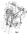
Fig. 1 is a perspective view showing a front side of a transfer device according to an embodiment of the present invention in a gripping position; -
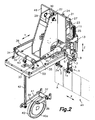
Fig. 2 is a perspective view showing a rear side of the transfer device in said gripping position; -
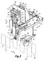
Fig. 3 is a perspective view showing the front side of the transfer device in a delivery position; -
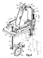
Fig. 4 is a perspective view showing the rear side of the transfer device in said delivery position; -
Fig. 5 is a schematic front view showing the arrangement of guide cams in detail; -
Fig. 6 is a cross-section view taken through a transverse vertical plane of the transfer device showing vertical movement operating means; and -
Fig. 7 is a schematic plan view illustrating the movements of grippers of the transfer device in relation to a supply container row and two filling container rows. - Referring first to
Figs. 1 to 4 , there is shown a transfer device according to an embodiment of the present invention. The transfer device serves to transfer empty flexible containers from one row of containers to two or more rows of containers applicable to an automatic packaging machine. In the embodiment illustrated inFigs. 1 to 4 , the transfer device is suitable for an automatic packaging machine comprising a container forming unit or a preformed container supply unit (not shown) provided with means for supplying a supply container row A1 in which flexible containers A are aligned in a horizontal longitudinal direction X and orientated in one and the same vertical plane, and a filling unit (not shown) provided with means for filling flexible containers A arranged in two parallel filling container rows A2, A3, and closing the containers once they are filled. - As described below, the transfer device of the present invention comprises means for transferring the flexible containers A from said supply container row A1 to said two filling container rows A2, A3. From the following description and from the attached drawings, a person skilled in the art could easily come up with the way of generalising the device of the present invention to transfer flexible containers from a supply container row to more than two filling container rows.
- The transfer device comprises a
base support 50 which in an operating situation is fixed in relation to a frame of the automatic packaging machine (not shown). Twotransverse guide elements base support 50 arranged in positions parallel to a horizontal transverse direction Y, perpendicular to said longitudinal direction X in which the supply container row A1 is arranged. Two gripper-holdingcarriages transverse guide elements carriages transverse guide elements - The two gripper-
holding carriages vertical guide elements vertical guide elements vertical guide elements - The guide supports 9, 10 have forks at their lower ends supporting respective
longitudinal guide elements longitudinal guide elements respective cam followers 19, 20 (Fig. 5 ) coupled to guidecams holding carriages cam followers guide cams longitudinal guide elements vertical guide elements - In each of the two gripper supports 5, 6 there is assembled a
corresponding gripper grippers conventional gripper actuators corresponding jaws - The aforementioned vertical operating means comprise a vertical movement actuator (not shown) controlled to simultaneously move the guide supports 9, 10 in said vertical direction Z between a lower position (
Figs. 1 and2 ) in which thegrippers Figs. 3 and4 ) in which thegrippers - As better shown in
Fig. 5 theguide cams Figs. 1 and2 ) which is reached when the guide supports 9, 10 are in said lower position and in which thegrippers Figs. 3 and4 ) which is reached when the guide supports 9, 10 are in said upper position and in which thegrippers - As shown in
Fig. 7 , this movement of the guide supports 9, 10 in the longitudinal direction X is necessary because the gap between the flexible containers A in the filling container rows A2, A3 is larger than the gap between the flexible containers A in the supply container row A1. This larger gap is due to the fact that the filling container rows A2, A3 are formed, for example, by flexible containers A secured in a plurality of carousel grippers P, each of which is provided with gripping means for holding two flexible containers A in parallel, and said carousel grippers P are coupled to a carousel (not shown) moving them along an endless trajectory. The gap between the carousel grippers P in the carousel determines the larger gap between the flexible containers A in the filling container rows A2, A3. Furthermore, although it can not be seen inFig. 7 , the filling container rows A2, A3 are located at a level higher than the supply container row A1. - The aforementioned transverse operating means comprise a transverse movement actuator (not shown) controlled to simultaneously move the gripper-holding
carriages Figs. 1 and2 ) which is simultaneous with the lower position of the guide supports 9, 10 and in which thegrippers Figs. 3 and4 ) which is simultaneous with the upper position of the guide supports 9, 10 and in which thegrippers carriages grippers -
Figs. 1 to 4 show one of the twogrippers 1 in the open position and theother gripper 2 in the closed position for merely illustrative purposes. Nevertheless, during the operation of the transfer device, the twogrippers Figs. 1 and2 ) with their jaws la, 2a arranged in the open position, and are then moved to the closed position to grip the two contiguous flexible containers A from the supply container row A1, and the twogrippers Figs. 3 and4 ) with their jaws la, 2a arranged in the closed position carrying respective flexible containers A, and are then moved to the open position to deliver the two flexible containers A to the two corresponding filling container rows A2, A3. - The vertical operating means comprise a raising
carriage 21 havingsupport arms 44 inserted ingrooves 45 formed in avertical plate 46 fixed with respect to thebase support 50. In a rear side of saidvertical plate 46 there is fixed a raisingvertical guide element 22 arranged in a position parallel to the vertical direction Z, and said supportarms 44 of the raisingcarriage 21 are coupled to said raisingvertical guide element 22 such that the raisingcarriage 21 can slide along same and along saidgrooves 45. - As shown in
Fig. 6 , in the embodiment illustrated the vertical operating means further comprise anendless belt 29 assembled onpulleys endless belt 29 has avertical section 29a adjacent to thevertical plate 46, and thesupport arms 44 of the raisingcarriage 21 are connected to said vertical section of the endless belt. The vertical movement actuator (not shown) is operatively connected to rotate one of saidpulleys upper pulley 30, and thereby alternately move the endless chain orbelt 29 and the raisingcarriage 21 in opposite directions. Twoconnection members carriage 21 in the vertical direction Z to the guide supports 9, 10 while at the same time allow the movements of the guide supports 9, 10 together with the gripper-holdingcarriages - To that end, in the raising
carriage 21 there are fixed two raisingtransverse guide elements connection members rolling means transverse guide elements endless belt 29 can be replaced by a roller chain or another similar flexible traction element, and that therolling means - Also alternatively, the means for moving the raising
carriage 21 in the vertical direction Z along the raisingvertical guide element 22 can include a mechanical transmission different from a belt or chain assembled on pulleys, such as a cam mechanism, oscillating shaft and connecting rod, for example, operated by a specific actuator or even by the same transverse movement actuator. - In the illustrated embodiment, the transverse operating means comprise an
oscillating shaft 32 assembled on thebase support 50 in a position parallel to the longitudinal direction X. Said transverse movement actuator (not shown) is operatively connected by a mechanical transmission to alternately rotate the oscillating shaft 32 a predetermined angle in opposite directions. Tworocker arms oscillating shaft 32 and alever arm 43 is fixed to a mid-region of theoscillating shaft 32. The oscillating movement of theoscillating shaft 32 is converted into a linear back and forth movement and transmitted to the gripper-holdingcarriages rods rocker arms carriages - A
follower shaft 37 having afollower arm 38 and atransmission arm 41 fixed thereto is arranged underneath thebase support 50. Acam follower 39 in the form of a small roller, which is inserted in agroove 40a defining arotating cam profile 40 is assembled in the mentionedfollower arm 38. The mentioned transverse movement actuator (not shown) is operatively connected to rotate the rotatingcam 40. Thecam follower 39 imparts an oscillating movement to thefollower shaft 37 by following the rotatingcam profile 40, and the oscillating movement of thefollower shaft 37 is transmitted to theoscillating shaft 32 by anoscillation transmission element 42 having a first end connected in an articulated manner to saidtransmission arm 41 fixed to thefollower shaft 37 and a second end connected in an articulated manner to thelever arm 43 fixed to theoscillating shaft 32. - The vertical and transverse movement actuators (not shown) are preferably electric motors, and more preferably electrically controlled servomotors to accurately coordinate the movements of the mobile parts and the positioning of the
grippers - Modifications and variations with respect to the embodiment shown and described will occur to a person skilled in the art without departing from the scope of the present invention as it is defined in the attached claims.
Claims (13)
- A transfer device for transferring empty flexible containers from one row of containers to two or more rows of containers applicable to an automatic packaging machine, wherein said automatic packaging machine comprises a container forming unit or a preformed container supply unit provided with means for supplying a supply container row (A1), in which flexible containers (A) are aligned in a horizontal longitudinal direction (X) and orientated in one and the same vertical plane, and a filling unit provided with means for filling flexible containers (A) arranged in at least two parallel filling container rows (A2, A3) and closing them, and wherein said transfer device comprises means for transferring the flexible containers (A) from said supply container row (A1) to said filling container rows (A2, A3), characterised in that the transfer device comprises:at least two transverse guide elements (15, 16) fixed to a base support (50) in positions parallel to a horizontal transverse direction (Y) perpendicular to said supply container row (A1);at least two gripper-holding carriages (13, 14) respectively assembled to be moved simultaneously in opposite directions along said transverse guide elements (15, 16) driven by transverse operating means,at least two vertical guide elements (11, 12) respectively fixed to said gripper-holding carriages (13, 14) in positions parallel to a vertical direction (Z);at least two guide supports (9, 10) respectively assembled to be moved along said vertical guide elements (11, 12) driven by vertical operating means;at least two longitudinal guide elements (7, 8) respectively fixed to said guide supports (9, 10) in positions parallel to said longitudinal direction (X);at least two respective gripper supports (5, 6) assembled to be moved along said longitudinal guide elements (7, 8);at least two cam followers (19, 20) respectively assembled in said gripper supports (5, 6) and coupled to guide cams (17, 18) arranged in the corresponding gripper-holding carriages (13, 14) to move the gripper supports (5, 6) along the longitudinal guide elements (7, 8) when the guide supports (9, 10) are moved along the vertical guide elements (11, 12); andat least two grippers (1, 2) respectively supported in the gripper supports (5, 6) and operated by respective gripper actuators (3, 4) to be moved between open and closed positions.
- The transfer device according to claim 1, characterised in that said vertical operating means comprise a vertical movement actuator controlled to simultaneously move the guide supports (9, 10) in said vertical direction (Z) between a lower position in which the grippers (1, 2) are in a suitable position to grip corresponding contiguous flexible containers (A) from the supply container row (A1), and an upper position in which the grippers (1, 2) are in a suitable position to release the flexible containers (A) at the level of the filling container rows (A2, A3) which are above the supply container row (A1).
- The transfer device according to claim 2, characterised in that said guide cams (17, 18) define a combined trajectory in longitudinal and vertical directions (X, Z) moving the gripper supports (5, 6) between a gripping position, which is reached when the guide supports (9, 10) are in said lower position and in which the grippers (1, 2) are separated in said longitudinal direction (X) by a distance equivalent to the distance between two contiguous flexible containers (A) in the supply container row (A1), and a delivery position, which is reached when the guide supports (9, 10) are in said upper position and in which the grippers (1, 2) are separated in the longitudinal direction (X) by a distance equivalent to the distance between two contiguous flexible containers (A) in the filling container rows (A2, A3).
- The transfer device according to claim 3, characterised in that said transverse operating means comprise a transverse movement actuator controlled to simultaneously move the gripper-holding carriages (13, 14) in said transverse direction (Y) between an aligned position which is simultaneous with the lower position of the guide supports (9, 10) and in which the grippers (1,2) are aligned with the supply container row (A1), and a misaligned position which is simultaneous with the upper position of the guide supports (9, 10) and in which the grippers (1, 2) are mutually misaligned and respectively aligned with the filling container rows (A2, A3).
- The transfer device according to claim 4, characterised in that in said misaligned position, the grippers (1, 2) are aligned with vertical planes symmetrical with respect to the vertical plane in which the supply container row (A1) is orientated.
- The transfer device according to claim 2, characterised in that the vertical operating means comprise a raising carriage (21) operated by said vertical movement actuator to be moved along a raising vertical guide element (22) fixed to the base support (50) in a position parallel to the vertical direction (Z), at least two raising transverse guide elements (23, 24) fixed to said raising carriage (21) in positions parallel to the transverse direction (Y), and at least two connection members (25, 26) having lower ends respectively fixed to the guide supports (9, 10) and upper ends provided with rolling or sliding means (27, 28) respectively coupled to said raising transverse guide elements (23, 24) such that they can be moved along same.
- The transfer device according to claim 6, characterised in that the vertical operating means further comprise an endless chain or belt (29) assembled on pulleys (30, 31) arranged such that said endless chain or belt (29) has a vertical section to which the raising carriage (21) is fixed, wherein the vertical movement actuator is operatively connected to rotate one of said pulleys (30, 31) and alternately move the endless chain or belt (29) in opposite directions.
- The transfer device according to claim 4, characterised in that the transverse operating means comprise an oscillating shaft (32) assembled on the base support (50) in a position parallel to the longitudinal direction (X) and operated by said transverse movement actuator to alternately rotate a predetermined angle in opposite directions, at least two rocker arms (33, 34) connected to said oscillating shaft (32) and at least two connecting rods (35, 36) having first ends respectively connected in an articulated manner to said rocker arms (33, 34) and second ends respectively connected in an articulated manner to the gripper-holding carriages (13, 14).
- The transfer device according to claim 8, characterised in that the transverse operating means further comprise a follower shaft (37), a follower arm (38) fixed to said follower shaft (37), a cam follower (39) assembled in said follower shaft (37) and arranged to follow the profile of a rotating cam (40), a transmission arm (41) fixed to the follower shaft (37), and an oscillation transmission element (42) having a first end connected in an articulated manner to said transmission arm (41) and a second end connected in an articulated manner to a lever arm (43) fixed to the oscillating shaft (32), wherein the transverse movement actuator is operatively connected to rotate said rotating cam (40).
- The transfer device according to claim 6 or 7, characterised in that said vertical movement actuator is an electric motor.
- The transfer device according to claim 10, characterised in that said vertical movement actuator is an electrically controlled servomotor.
- The transfer device according to claim 8 or 9, characterised in that said transverse movement actuator is an electric motor.
- The transfer device according to claim 12, characterised in that said transverse movement actuator is an electrically controlled servomotor.
Applications Claiming Priority (1)
| Application Number | Priority Date | Filing Date | Title |
|---|---|---|---|
| ES201100518A ES2392285B1 (en) | 2011-05-11 | 2011-05-11 | TRANSFER DEVICE FOR TRANSFERING EMPTY FLEXIBLE CONTAINERS FROM A ROW OF CONTAINERS TO TWO OR MORE ROWS OF CONTAINERS IN AN AUTOMATIC PACKING MACHINE |
Publications (2)
| Publication Number | Publication Date |
|---|---|
| EP2522583A1 EP2522583A1 (en) | 2012-11-14 |
| EP2522583B1 true EP2522583B1 (en) | 2013-10-16 |
Family
ID=46168371
Family Applications (1)
| Application Number | Title | Priority Date | Filing Date |
|---|---|---|---|
| EP20120380022 Active EP2522583B1 (en) | 2011-05-11 | 2012-05-10 | Transfer device for transferring empty flexible packages from a package row to two or more package rows applicable to an automatic packaging machine |
Country Status (2)
| Country | Link |
|---|---|
| EP (1) | EP2522583B1 (en) |
| ES (1) | ES2392285B1 (en) |
Families Citing this family (9)
| Publication number | Priority date | Publication date | Assignee | Title |
|---|---|---|---|---|
| US9776334B2 (en) | 2013-03-14 | 2017-10-03 | Kla-Tencor Corporation | Apparatus and method for automatic pitch conversion of pick and place heads, pick and place head and pick and place device |
| WO2014143436A1 (en) * | 2013-03-14 | 2014-09-18 | Kla-Tencor Corporation | Apparatus and method for automatic pitch conversion of pick and place heads, pick and place head and pick and place device |
| CN103350790A (en) * | 2013-07-01 | 2013-10-16 | 安徽正远包装科技有限公司 | Bag supplying mechanism capable of stably operating between bag supplying and bag taking |
| ES2539202B1 (en) * | 2013-12-23 | 2016-04-14 | Mespack, Sl | DEVICE AND TRANSFER METHOD TO TRANSFER FLEXIBLE PACKAGING |
| ES2550372B1 (en) * | 2014-05-05 | 2016-07-21 | Mespack, Sl | Line change device for automatic horizontal machine for forming and filling flexible containers |
| CN106477322B (en) * | 2016-12-23 | 2018-09-14 | 福建晋江浔兴拉链科技有限公司 | A kind of the automatic of silent injection molding machine goes material bone equipment and its application method |
| CN106743577B (en) * | 2017-01-17 | 2018-11-30 | 浙江优通自动化技术有限公司 | A kind of three-freedom mechanical arm device and manipulator plateform system |
| CN109879009A (en) * | 2019-03-05 | 2019-06-14 | 江苏理工学院 | A kind of fan radiator automatic loading and unloading mechanism and its working method |
| CN113104552B (en) * | 2021-03-25 | 2022-07-15 | 成都城投建筑工程有限公司 | Pile foundation construction device under high-voltage line and construction method thereof |
Family Cites Families (8)
| Publication number | Priority date | Publication date | Assignee | Title |
|---|---|---|---|---|
| US2753097A (en) * | 1951-07-13 | 1956-07-03 | Bemis Bro Bag Co | Bag feeding and filling machines |
| ES2117929B1 (en) | 1995-04-17 | 1999-03-16 | Bossar S A | FLEXIBLE CONTAINER CONVEYOR, APPLICABLE ON HORIZONTAL MACHINES. |
| ES2222060B1 (en) * | 2001-12-21 | 2006-03-16 | Camilo Batalla Teixidor | AUTOMATIC PACKAGING MACHINE. |
| ES2226517B1 (en) | 2002-02-20 | 2006-06-01 | Volpak, S.A. | TRANSFER DEVICE FOR EMPTY FLEXIBLE CONTAINERS, FOR AUTOMATIC PACKAGING MACHINES. |
| ES2229836B1 (en) | 2002-02-20 | 2006-06-16 | Volpak, S.A. | FLEXIBLE PACKAGING TRANSPORTATION DEVICE FOR AUTOMATIC PACKAGING MACHINES. |
| CA2445607A1 (en) * | 2002-10-18 | 2004-04-18 | Boss Packaging Inc. | Bag presenter for a packaging machine |
| ES2257180B1 (en) * | 2004-10-13 | 2007-08-16 | Volpak, S.A. | PACKAGING TRANSPORTATION DEVICE. |
| ITBO20070203A1 (en) * | 2007-03-21 | 2008-09-22 | Aroma Systems Srl | MACHINE FOR FILLING BAGS OR BAGS ALSO IN A CONTROLLED ATMOSPHERE |
-
2011
- 2011-05-11 ES ES201100518A patent/ES2392285B1/en active Active
-
2012
- 2012-05-10 EP EP20120380022 patent/EP2522583B1/en active Active
Also Published As
| Publication number | Publication date |
|---|---|
| ES2392285B1 (en) | 2013-10-16 |
| EP2522583A1 (en) | 2012-11-14 |
| ES2392285A1 (en) | 2012-12-07 |
Similar Documents
| Publication | Publication Date | Title |
|---|---|---|
| EP2522583B1 (en) | Transfer device for transferring empty flexible packages from a package row to two or more package rows applicable to an automatic packaging machine | |
| US11332324B2 (en) | Transport device having transport rake and counter rake | |
| EP2864227B1 (en) | Apparatus for orderly supply of a group of trays to a sealing machine of said trays, with application of a covering film | |
| EP3907162A1 (en) | Plant for processing containers | |
| EP2522584B1 (en) | Carousel for a horizontal-type automatic packaging machine | |
| US9650165B2 (en) | Tray sealer | |
| EP3321195B1 (en) | Horizontal-type automatic packaging machine | |
| CZ78599A3 (en) | Mounting machine | |
| US11787645B2 (en) | Conveyor device for conveying flexible containers along a packaging line | |
| EP3580038B1 (en) | Assembly for manufacturing fillable containers and a packaging line comprising such manufacturing assembly and a corresponing method | |
| US8439624B2 (en) | Transfer apparatus | |
| IT9047879A1 (en) | ROCK REPLACEMENT EQUIPMENT. | |
| EP2942298B1 (en) | Line-changing device for an automatic horizontal flexible container forming and filling machine | |
| CN203111579U (en) | Bag supplying mechanism for bag-feeding type packing machine | |
| EP0734949B1 (en) | Device for forming groups of articles in cartoning machines and the like | |
| US20230331417A1 (en) | Packaging machine with a grouping device and method for producing single-layer groups of partially overlapping products | |
| CN110816955A (en) | Material pushing device | |
| KR102409165B1 (en) | Pick and place apparatus with up and down flip | |
| EP3274151B1 (en) | Thermoforming machine and method | |
| CN211365092U (en) | Material pushing device | |
| KR102353155B1 (en) | Bag supply apparatus | |
| JP5056151B2 (en) | Goods transfer device | |
| KR20160097990A (en) | Mold system using two-row transfer device | |
| KR20230075646A (en) | Gripper device and automatic product supply apparatus having the same | |
| RU2248313C1 (en) | Device for packing piece goods |
Legal Events
| Date | Code | Title | Description |
|---|---|---|---|
| PUAI | Public reference made under article 153(3) epc to a published international application that has entered the european phase |
Free format text: ORIGINAL CODE: 0009012 |
|
| AK | Designated contracting states |
Kind code of ref document: A1 Designated state(s): AL AT BE BG CH CY CZ DE DK EE ES FI FR GB GR HR HU IE IS IT LI LT LU LV MC MK MT NL NO PL PT RO RS SE SI SK SM TR |
|
| AX | Request for extension of the european patent |
Extension state: BA ME |
|
| 17P | Request for examination filed |
Effective date: 20130130 |
|
| RIC1 | Information provided on ipc code assigned before grant |
Ipc: B65B 43/12 20060101AFI20130325BHEP Ipc: B65G 47/90 20060101ALI20130325BHEP Ipc: B65B 43/46 20060101ALI20130325BHEP |
|
| GRAP | Despatch of communication of intention to grant a patent |
Free format text: ORIGINAL CODE: EPIDOSNIGR1 |
|
| INTG | Intention to grant announced |
Effective date: 20130705 |
|
| GRAS | Grant fee paid |
Free format text: ORIGINAL CODE: EPIDOSNIGR3 |
|
| GRAA | (expected) grant |
Free format text: ORIGINAL CODE: 0009210 |
|
| AK | Designated contracting states |
Kind code of ref document: B1 Designated state(s): AL AT BE BG CH CY CZ DE DK EE ES FI FR GB GR HR HU IE IS IT LI LT LU LV MC MK MT NL NO PL PT RO RS SE SI SK SM TR |
|
| REG | Reference to a national code |
Ref country code: GB Ref legal event code: FG4D |
|
| REG | Reference to a national code |
Ref country code: CH Ref legal event code: EP |
|
| REG | Reference to a national code |
Ref country code: IE Ref legal event code: FG4D |
|
| REG | Reference to a national code |
Ref country code: AT Ref legal event code: REF Ref document number: 636370 Country of ref document: AT Kind code of ref document: T Effective date: 20131115 |
|
| REG | Reference to a national code |
Ref country code: DE Ref legal event code: R096 Ref document number: 602012000401 Country of ref document: DE Effective date: 20131212 |
|
| REG | Reference to a national code |
Ref country code: NL Ref legal event code: VDEP Effective date: 20131016 |
|
| REG | Reference to a national code |
Ref country code: AT Ref legal event code: MK05 Ref document number: 636370 Country of ref document: AT Kind code of ref document: T Effective date: 20131016 |
|
| REG | Reference to a national code |
Ref country code: LT Ref legal event code: MG4D |
|
| PG25 | Lapsed in a contracting state [announced via postgrant information from national office to epo] |
Ref country code: NO Free format text: LAPSE BECAUSE OF FAILURE TO SUBMIT A TRANSLATION OF THE DESCRIPTION OR TO PAY THE FEE WITHIN THE PRESCRIBED TIME-LIMIT Effective date: 20140116 Ref country code: HR Free format text: LAPSE BECAUSE OF FAILURE TO SUBMIT A TRANSLATION OF THE DESCRIPTION OR TO PAY THE FEE WITHIN THE PRESCRIBED TIME-LIMIT Effective date: 20131016 Ref country code: IS Free format text: LAPSE BECAUSE OF FAILURE TO SUBMIT A TRANSLATION OF THE DESCRIPTION OR TO PAY THE FEE WITHIN THE PRESCRIBED TIME-LIMIT Effective date: 20140216 Ref country code: FI Free format text: LAPSE BECAUSE OF FAILURE TO SUBMIT A TRANSLATION OF THE DESCRIPTION OR TO PAY THE FEE WITHIN THE PRESCRIBED TIME-LIMIT Effective date: 20131016 Ref country code: BE Free format text: LAPSE BECAUSE OF FAILURE TO SUBMIT A TRANSLATION OF THE DESCRIPTION OR TO PAY THE FEE WITHIN THE PRESCRIBED TIME-LIMIT Effective date: 20131016 Ref country code: SE Free format text: LAPSE BECAUSE OF FAILURE TO SUBMIT A TRANSLATION OF THE DESCRIPTION OR TO PAY THE FEE WITHIN THE PRESCRIBED TIME-LIMIT Effective date: 20131016 Ref country code: NL Free format text: LAPSE BECAUSE OF FAILURE TO SUBMIT A TRANSLATION OF THE DESCRIPTION OR TO PAY THE FEE WITHIN THE PRESCRIBED TIME-LIMIT Effective date: 20131016 Ref country code: LT Free format text: LAPSE BECAUSE OF FAILURE TO SUBMIT A TRANSLATION OF THE DESCRIPTION OR TO PAY THE FEE WITHIN THE PRESCRIBED TIME-LIMIT Effective date: 20131016 |
|
| PG25 | Lapsed in a contracting state [announced via postgrant information from national office to epo] |
Ref country code: LV Free format text: LAPSE BECAUSE OF FAILURE TO SUBMIT A TRANSLATION OF THE DESCRIPTION OR TO PAY THE FEE WITHIN THE PRESCRIBED TIME-LIMIT Effective date: 20131016 Ref country code: ES Free format text: LAPSE BECAUSE OF FAILURE TO SUBMIT A TRANSLATION OF THE DESCRIPTION OR TO PAY THE FEE WITHIN THE PRESCRIBED TIME-LIMIT Effective date: 20131016 Ref country code: RS Free format text: LAPSE BECAUSE OF FAILURE TO SUBMIT A TRANSLATION OF THE DESCRIPTION OR TO PAY THE FEE WITHIN THE PRESCRIBED TIME-LIMIT Effective date: 20131016 Ref country code: CY Free format text: LAPSE BECAUSE OF FAILURE TO SUBMIT A TRANSLATION OF THE DESCRIPTION OR TO PAY THE FEE WITHIN THE PRESCRIBED TIME-LIMIT Effective date: 20131016 Ref country code: AT Free format text: LAPSE BECAUSE OF FAILURE TO SUBMIT A TRANSLATION OF THE DESCRIPTION OR TO PAY THE FEE WITHIN THE PRESCRIBED TIME-LIMIT Effective date: 20131016 |
|
| PG25 | Lapsed in a contracting state [announced via postgrant information from national office to epo] |
Ref country code: PT Free format text: LAPSE BECAUSE OF FAILURE TO SUBMIT A TRANSLATION OF THE DESCRIPTION OR TO PAY THE FEE WITHIN THE PRESCRIBED TIME-LIMIT Effective date: 20140217 |
|
| REG | Reference to a national code |
Ref country code: DE Ref legal event code: R097 Ref document number: 602012000401 Country of ref document: DE |
|
| PG25 | Lapsed in a contracting state [announced via postgrant information from national office to epo] |
Ref country code: EE Free format text: LAPSE BECAUSE OF FAILURE TO SUBMIT A TRANSLATION OF THE DESCRIPTION OR TO PAY THE FEE WITHIN THE PRESCRIBED TIME-LIMIT Effective date: 20131016 |
|
| PLBE | No opposition filed within time limit |
Free format text: ORIGINAL CODE: 0009261 |
|
| STAA | Information on the status of an ep patent application or granted ep patent |
Free format text: STATUS: NO OPPOSITION FILED WITHIN TIME LIMIT |
|
| PG25 | Lapsed in a contracting state [announced via postgrant information from national office to epo] |
Ref country code: SK Free format text: LAPSE BECAUSE OF FAILURE TO SUBMIT A TRANSLATION OF THE DESCRIPTION OR TO PAY THE FEE WITHIN THE PRESCRIBED TIME-LIMIT Effective date: 20131016 Ref country code: RO Free format text: LAPSE BECAUSE OF FAILURE TO SUBMIT A TRANSLATION OF THE DESCRIPTION OR TO PAY THE FEE WITHIN THE PRESCRIBED TIME-LIMIT Effective date: 20131016 Ref country code: CZ Free format text: LAPSE BECAUSE OF FAILURE TO SUBMIT A TRANSLATION OF THE DESCRIPTION OR TO PAY THE FEE WITHIN THE PRESCRIBED TIME-LIMIT Effective date: 20131016 Ref country code: IT Free format text: LAPSE BECAUSE OF FAILURE TO SUBMIT A TRANSLATION OF THE DESCRIPTION OR TO PAY THE FEE WITHIN THE PRESCRIBED TIME-LIMIT Effective date: 20131016 Ref country code: PL Free format text: LAPSE BECAUSE OF FAILURE TO SUBMIT A TRANSLATION OF THE DESCRIPTION OR TO PAY THE FEE WITHIN THE PRESCRIBED TIME-LIMIT Effective date: 20131016 |
|
| 26N | No opposition filed |
Effective date: 20140717 |
|
| PG25 | Lapsed in a contracting state [announced via postgrant information from national office to epo] |
Ref country code: DK Free format text: LAPSE BECAUSE OF FAILURE TO SUBMIT A TRANSLATION OF THE DESCRIPTION OR TO PAY THE FEE WITHIN THE PRESCRIBED TIME-LIMIT Effective date: 20131016 |
|
| REG | Reference to a national code |
Ref country code: DE Ref legal event code: R097 Ref document number: 602012000401 Country of ref document: DE Effective date: 20140717 |
|
| PG25 | Lapsed in a contracting state [announced via postgrant information from national office to epo] |
Ref country code: LU Free format text: LAPSE BECAUSE OF FAILURE TO SUBMIT A TRANSLATION OF THE DESCRIPTION OR TO PAY THE FEE WITHIN THE PRESCRIBED TIME-LIMIT Effective date: 20140510 |
|
| PG25 | Lapsed in a contracting state [announced via postgrant information from national office to epo] |
Ref country code: MC Free format text: LAPSE BECAUSE OF FAILURE TO SUBMIT A TRANSLATION OF THE DESCRIPTION OR TO PAY THE FEE WITHIN THE PRESCRIBED TIME-LIMIT Effective date: 20131016 |
|
| REG | Reference to a national code |
Ref country code: IE Ref legal event code: MM4A |
|
| PG25 | Lapsed in a contracting state [announced via postgrant information from national office to epo] |
Ref country code: SI Free format text: LAPSE BECAUSE OF FAILURE TO SUBMIT A TRANSLATION OF THE DESCRIPTION OR TO PAY THE FEE WITHIN THE PRESCRIBED TIME-LIMIT Effective date: 20131016 |
|
| PG25 | Lapsed in a contracting state [announced via postgrant information from national office to epo] |
Ref country code: IE Free format text: LAPSE BECAUSE OF NON-PAYMENT OF DUE FEES Effective date: 20140510 |
|
| REG | Reference to a national code |
Ref country code: CH Ref legal event code: PL |
|
| PG25 | Lapsed in a contracting state [announced via postgrant information from national office to epo] |
Ref country code: CH Free format text: LAPSE BECAUSE OF NON-PAYMENT OF DUE FEES Effective date: 20150531 Ref country code: LI Free format text: LAPSE BECAUSE OF NON-PAYMENT OF DUE FEES Effective date: 20150531 |
|
| PG25 | Lapsed in a contracting state [announced via postgrant information from national office to epo] |
Ref country code: MT Free format text: LAPSE BECAUSE OF FAILURE TO SUBMIT A TRANSLATION OF THE DESCRIPTION OR TO PAY THE FEE WITHIN THE PRESCRIBED TIME-LIMIT Effective date: 20131016 |
|
| PG25 | Lapsed in a contracting state [announced via postgrant information from national office to epo] |
Ref country code: SM Free format text: LAPSE BECAUSE OF FAILURE TO SUBMIT A TRANSLATION OF THE DESCRIPTION OR TO PAY THE FEE WITHIN THE PRESCRIBED TIME-LIMIT Effective date: 20131016 |
|
| REG | Reference to a national code |
Ref country code: FR Ref legal event code: PLFP Year of fee payment: 5 |
|
| PG25 | Lapsed in a contracting state [announced via postgrant information from national office to epo] |
Ref country code: GR Free format text: LAPSE BECAUSE OF FAILURE TO SUBMIT A TRANSLATION OF THE DESCRIPTION OR TO PAY THE FEE WITHIN THE PRESCRIBED TIME-LIMIT Effective date: 20140117 Ref country code: BG Free format text: LAPSE BECAUSE OF FAILURE TO SUBMIT A TRANSLATION OF THE DESCRIPTION OR TO PAY THE FEE WITHIN THE PRESCRIBED TIME-LIMIT Effective date: 20131016 |
|
| PG25 | Lapsed in a contracting state [announced via postgrant information from national office to epo] |
Ref country code: HU Free format text: LAPSE BECAUSE OF FAILURE TO SUBMIT A TRANSLATION OF THE DESCRIPTION OR TO PAY THE FEE WITHIN THE PRESCRIBED TIME-LIMIT; INVALID AB INITIO Effective date: 20120510 Ref country code: TR Free format text: LAPSE BECAUSE OF FAILURE TO SUBMIT A TRANSLATION OF THE DESCRIPTION OR TO PAY THE FEE WITHIN THE PRESCRIBED TIME-LIMIT Effective date: 20131016 |
|
| REG | Reference to a national code |
Ref country code: FR Ref legal event code: PLFP Year of fee payment: 6 |
|
| REG | Reference to a national code |
Ref country code: FR Ref legal event code: PLFP Year of fee payment: 7 |
|
| PG25 | Lapsed in a contracting state [announced via postgrant information from national office to epo] |
Ref country code: MK Free format text: LAPSE BECAUSE OF FAILURE TO SUBMIT A TRANSLATION OF THE DESCRIPTION OR TO PAY THE FEE WITHIN THE PRESCRIBED TIME-LIMIT Effective date: 20131016 |
|
| PG25 | Lapsed in a contracting state [announced via postgrant information from national office to epo] |
Ref country code: AL Free format text: LAPSE BECAUSE OF FAILURE TO SUBMIT A TRANSLATION OF THE DESCRIPTION OR TO PAY THE FEE WITHIN THE PRESCRIBED TIME-LIMIT Effective date: 20131016 |
|
| P01 | Opt-out of the competence of the unified patent court (upc) registered |
Effective date: 20230330 |
|
| PGFP | Annual fee paid to national office [announced via postgrant information from national office to epo] |
Ref country code: FR Payment date: 20230531 Year of fee payment: 12 Ref country code: DE Payment date: 20230530 Year of fee payment: 12 |
|
| PGFP | Annual fee paid to national office [announced via postgrant information from national office to epo] |
Ref country code: GB Payment date: 20230529 Year of fee payment: 12 |