EP2522476B1 - Method for producing a coated board element from a wooden material with an edge strip. - Google Patents
Method for producing a coated board element from a wooden material with an edge strip. Download PDFInfo
- Publication number
- EP2522476B1 EP2522476B1 EP12167224.0A EP12167224A EP2522476B1 EP 2522476 B1 EP2522476 B1 EP 2522476B1 EP 12167224 A EP12167224 A EP 12167224A EP 2522476 B1 EP2522476 B1 EP 2522476B1
- Authority
- EP
- European Patent Office
- Prior art keywords
- edge
- glue
- adhesive
- strip
- edge strip
- Prior art date
- Legal status (The legal status is an assumption and is not a legal conclusion. Google has not performed a legal analysis and makes no representation as to the accuracy of the status listed.)
- Revoked
Links
Images
Classifications
-
- B—PERFORMING OPERATIONS; TRANSPORTING
- B27—WORKING OR PRESERVING WOOD OR SIMILAR MATERIAL; NAILING OR STAPLING MACHINES IN GENERAL
- B27D—WORKING VENEER OR PLYWOOD
- B27D5/00—Other working of veneer or plywood specially adapted to veneer or plywood
- B27D5/006—Trimming, chamfering or bevelling edgings, e.g. lists
-
- B—PERFORMING OPERATIONS; TRANSPORTING
- B29—WORKING OF PLASTICS; WORKING OF SUBSTANCES IN A PLASTIC STATE IN GENERAL
- B29C—SHAPING OR JOINING OF PLASTICS; SHAPING OF MATERIAL IN A PLASTIC STATE, NOT OTHERWISE PROVIDED FOR; AFTER-TREATMENT OF THE SHAPED PRODUCTS, e.g. REPAIRING
- B29C63/00—Lining or sheathing, i.e. applying preformed layers or sheathings of plastics; Apparatus therefor
- B29C63/0026—Lining or sheathing, i.e. applying preformed layers or sheathings of plastics; Apparatus therefor an edge face with strip material, e.g. a panel edge
- B29C63/003—Lining or sheathing, i.e. applying preformed layers or sheathings of plastics; Apparatus therefor an edge face with strip material, e.g. a panel edge continuously
-
- B—PERFORMING OPERATIONS; TRANSPORTING
- B29—WORKING OF PLASTICS; WORKING OF SUBSTANCES IN A PLASTIC STATE IN GENERAL
- B29C—SHAPING OR JOINING OF PLASTICS; SHAPING OF MATERIAL IN A PLASTIC STATE, NOT OTHERWISE PROVIDED FOR; AFTER-TREATMENT OF THE SHAPED PRODUCTS, e.g. REPAIRING
- B29C2793/00—Shaping techniques involving a cutting or machining operation
- B29C2793/009—Shaping techniques involving a cutting or machining operation after shaping
Definitions
- the invention relates to a method for producing a coated board element made of wood material with an edge strip which is preferably attached with an adhesive hot melt adhesive to the uncoated edge region of the plate member, and wherein the reproached on a roll edge strips with a small excess with its adhesive side of the adhesive coated edge portion of the plate member is pressed, and wherein the adhesive emerging from the adhesive joint during the setting process due to the applied pressure and the excess of the edge strip is removed from the edge regions of the plate member at the top and / or bottom.
- a spray device is provided before the strip inlet, with a liquid release agent on the top and bottom Edge region of the respective plate broadside is sprayed.
- the release agent is intended primarily to reduce the effort when, for example, mechanical cleaning equipment, such as so-called buffing remove the glue travel to meet in this way the qualitative requirements of the plate, so that a surface is created in the edge region, which has no residues ,
- edge strip is coated with hot melt adhesive in a continuous process and then pressed by pinch rollers to the edge, the edge strip has a greater width than the cross-sectional length of the tread surface so that it protrudes.
- the hotmelt adhesive is cooled in the edge strip region which has not yet been glued and then cut off precisely to fit.
- a tailor edge strip is provided to a profiled edge.
- the production of a coated plate element is also known.
- the method for producing a coated plate element with at least one edge having a tapered narrow surface is by gluing a band-shaped coating on the narrow surface (edge) of the coated plate member, which is made greater in width than the width of the narrow surface to be coated, under pressure adheres, wherein the supernatant of the pad is separated after cooling the hot melt adhesive on the supernatant of the pad.
- it is proposed according to the method that one first presses the coating completely to the width of the narrow surface to be coated, before cooling the hot melt adhesive on the supernatant of the pad and finally separates the supernatant.
- coolant in the form of finely divided droplets is used.
- EP 1 516 711 discloses a release agent and a process for the production of plastic moldings from polyurethane, wherein for their preparation using certain additives that reduce the concentration of undesirable potentially harmful substances in the edge zone and on the surface of the molding, without negatively affecting the other mechanical properties.
- DE 10 2005 061 245 B3 describes a method in which, after gluing a plastic or veneer strip to the edge of a plate, a separating or cleaning agent on the upper and lower edge region on the respective plate width side a separating or cleaning agent in a strip with pre-selectable width edge-mounted on the upper and the lower edge region of the respective plate broadside and / or can be applied to the pressure element.
- the present invention is therefore based on the object, a method and an agent or substance in such a way that overcomes the disadvantages, in particular after passing through the coated plate member no lubricant film remains, the substance should not be flammable, and by the regulations the dangerous goods regulation is excluded.
- the advantages achieved with the invention consist essentially in the fact that due to the application of a substance, which in particular affects the adhesiveness of the adhesive, it is ensured that the adhesive residues no longer remain adhering to the surface of the plate element, but instead form particles in the continuous process, which can be easily and simply detached or removed from the surface.
- the substance is in this case applied in strips on the edge regions of top and bottom, wherein the substance as such consists of polymers dispersed in water, which forms a wax film on the edge regions.
- the wax film with the contained adhesive particles by means of buffing trained rotating brushes away from the surfaces of the edge portion.
- a second wax film is preferably applied before brushing, to form a protective film on the adhesive joint.
- the substance consists of a solvent-free and silicone-free agent, which builds on a water-based.
- the waxy agent provides a seal as well as coating the surface which both cools and lubricates the flat and profile scrapers and their skids.
- As a result of the wax film results in cooling and lubricating flat and profile scrapers and their skids, as well as cooling the so-called buffing units.
- a re-adhesion and subsequent contamination in the adhesive area, for example when storing, the edge-coated plate member is prevented.
- the coating remains after buffing as a dry, strong wax film.
- the wax film also prevents gluing the Tastkufen, sliding shoes, pressure rollers or sensing rollers.
- the processing tools remain free of adhesive residues, resulting in longer service life of the individual units and a better cleaning effect.
- the continuous coating of 15 to 20 mm width ensures the cleanliness of the coated areas, leaving a dry but water-soluble protective film.
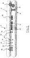
- FIG. 1 shows in side view a device 1 with which an edge strip 2 is added to the edge region 3 of a coated plate element 4.
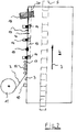
- the device 1 here consists of stacked endless conveyors 5 and 6, the plate member 4 according to the direction of the arrow 7 in FIG. 2 through the device 1.
- formatting devices 8 and 9 are provided, which in particular format the incoming plate element 4.
- Behind the formatter 8 and 9 is followed by a gluing station 10 which, in particular, applies a glue layer formed as an adhesive to the edge region 3.
- Behind the gluing station 10 the supply of the edge strip 2, which is unwound from a roll 11, as is better in the FIG. 2 will be shown.
- the edge strip 2 is pressed against the glued edge region 3.
- glue is pressed out of the glue joint 13, which is wetted with a spraying device consisting of nozzles 14 with a substance.
- nozzles 14 Downstream of the nozzles 14 are cutters 15, which in particular mill off the projecting region of the pressed-on edge strip 2.
- the milled edge strip 2 is then smoothed out in each case with flat and profile scrapers 16 and 17, wherein the finishing is performed with the buffing wheels or brushes 18, with which the applied spray layer or accumulated chips are removed.
- the edge strip 2 is attached to the uncoated edge portion 3 of the plate member 4 with an adhesive, preferably hot melt adhesive.
- an adhesive preferably hot melt adhesive.
- the edge strip 2 held on the roll 11 is pressed with a slight oversize with its adhesive side against the adhesive-coated edge region 3 of the plate element 4.
- a slightly exaggerated bead of adhesive can form on the top and bottom of the plate segment 4.
- this adhesive bead with the supernatant of the edge strip 2, which forms the oversize here, away from the edge portion 3 of the plate member 4 at the top and bottom, which is done here for example with the cutters 15 or with the profile scraper 17.
- a substance is applied to the edge region 3 of the top and bottom of the plate member 4 before the setting process of the adhesive, which exits the adhesive joint 13 exiting excess adhesive residues deactivate in their adhesion, so that form non-adhesive adhesive particles, which are removed when removing the protruding edge strip 2 from the edge portion 3 with.
- the adhesive residues are scraped off with the profile scraper blade 17 or are milled off with a milling cutter 15, chip particles of plastic and adhesive are formed, these being enclosed by the wax film 19, which in strip form 20 rests on the edge regions 3 of the top and bottom side of the panel element 4 was applied.
- the adhesive residues present in the wax film 19 are thereby deactivated in their adhesive action, so that they are no longer able to adhere to the surface of the plate element 4.
- the sprayed-on substance consists of a polymer-dispersed fluid in water, which forms a wax film on the edge region 3.
- the wax film with the contained adhesive particles is removed from the surface of the edge region 3 by means of the rotating brushes 18 designed as buffing wheels.
- a second wax film is preferably applied in front of the brushes 18 to form a protective film on the adhesive joint 13. The brushes then rub the wax particles into the adhesive joint 13 so that a clean seal between edge strips 2 and coated top and bottom surfaces.
- a wax film may also be applied in front of blades 16 and 17.
Description
Verfahren zur Herstellung eines beschichteten Plattenelementes aus Holzwerkstoff mit einem Kantenstreifen gemäß dem Oberbegriff des Anspruchs 1. Ein solches Verfahren ist aus dem Dokument
Die Erfindung betrifft ein Verfahren zur Herstellung eines beschichteten Plattenelementes aus Holzwerkstoff mit einem Kantenstreifen, der mit einem Kleber vorzugsweise Schmelzkleber an den unbeschichteten Kantenbereich des Plattenelementes befestigt wird, und wobei der auf einer Rolle vorgehaltene Kantenstreifen mit einem geringen Übermaß mit seiner Klebeseite an den mit Kleber beschichteten Kantenbereich des Plattenelementes angedrückt wird, und wobei der aus der Klebefuge während des Abbindeprozesses in Folge des aufgebrachten Drucks austretende Kleber sowie das Übermaß des Kantenstreifens von den Kantenbereichen des Plattenelements an der Oberseite und/oder der Unterseite entfernt wird.The invention relates to a method for producing a coated board element made of wood material with an edge strip which is preferably attached with an adhesive hot melt adhesive to the uncoated edge region of the plate member, and wherein the reproached on a roll edge strips with a small excess with its adhesive side of the adhesive coated edge portion of the plate member is pressed, and wherein the adhesive emerging from the adhesive joint during the setting process due to the applied pressure and the excess of the edge strip is removed from the edge regions of the plate member at the top and / or bottom.
Aus dem Stand der Technik sind Vorrichtungen aber auch Verfahren bekannt, die insbesondere die Anbringung eines Streifens an den Kantenbereich einer beschichteten Platte beschreiben. So wird beispielsweise in der
Eine weitere Ausführungsform des Standes der Technik wird in der
Aus der
Eine weitere Ausführungsform eines Verfahrens des Standes der Technik ist in der
Ein weiteres Dokument des Standes der Technik, die
Aus dem Stand der Technik gemäß der
Zu dem dokumentiert der Stand der Technik Substanzen nach der
Bei all diesen aus dem Stand der Technik beschriebenen Verfahren und deren verwendeten Trennmittel wird es als nachteilig angesehen, dass insbesondere die Verwendung eines Fluids, bestehend aus Wasser mit Alkohol und Tensiden, wie dies in der letztbeschriebenen Druckschrift vorgeschlagen wird, und welches als Antielektrostatikum wirken soll, über die Bearbeitungsschritte, wie Fräsen bzw. die Bearbeitung mit Flach- oder Profilziehklingen sowie die Bearbeitung mit Schwabbelaggregaten einen Restschmierfilm auf dem Kantenbereich verursacht, der nur unter hohem Aufwand und Reinigungseinsatz von dem Kantenbereich entfernt werden kann. Dies bedingt auch durch die überstehenden Kleberreste, die auf der Fläche in Verbindung mit der aufgetragenen Sprühflüssigkeit verrieben werden, so dass sich hier ein bleibender Schmierfilm bildet. Zudem beinhaltet das Fluid eine leicht entzündbare Substanz, was insbesondere den Umgang des Fluids bei der Lagerhaltung und dem Transport hinsichtlich der Gefahrengutverordnung erschwert. So ist es beispielsweise nur erlaubt das Fluid in explosionsgeschützten Räumen zu lagern.In all these methods described in the prior art and their release agents used, it is considered disadvantageous that in particular the use of a fluid consisting of water with alcohol and surfactants, as proposed in the last-mentioned document, and which is to act as an anti-static , about the processing steps, such as milling or processing with flat or profiled scrapers and processing with buffing a residual lubricating film on the edge area causes that can be removed only with great effort and cleaning use of the edge area. This is also due to the protruding adhesive residues that are rubbed on the surface in conjunction with the applied spray liquid, so that here forms a permanent lubricating film. In addition, the fluid contains a highly flammable substance, which makes it difficult in particular the handling of the fluid during storage and transport in terms of dangerous goods regulation. For example, it is only allowed to store the fluid in explosion-proof rooms.
Der vorliegenden Erfindung liegt daher die Aufgabe zugrunde, ein Verfahren sowie ein Mittel oder eine Substanz so auszubilden, die die geschilderten Nachteile überwindet, wobei insbesondere nach Durchlauf des beschichteten Plattenelementes kein Schmierfilm zurückbleibt, wobei die Substanz nicht brennbar sein soll, und die von den Vorschriften der Gefahrengutverordnung ausgenommen ist.The present invention is therefore based on the object, a method and an agent or substance in such a way that overcomes the disadvantages, in particular after passing through the coated plate member no lubricant film remains, the substance should not be flammable, and by the regulations the dangerous goods regulation is excluded.
Erfindungsgemäß wird das Problem mit den Merkmalen des Anspruchs 1 gelöst; vorteilhafte Ausgestaltungen der Erfindung ergeben sich aus den Unteransprüchen.According to the invention the problem is solved with the features of
Die mit der der Erfindung erreichten Vorteile bestehen im Wesentlichen darin, dass aufgrund des Auftragens einer Substanz, die insbesondere die Haftfähigkeit des Klebers beeinflusst, sichergestellt wird, dass die Kleberreste nicht mehr an der Oberfläche des Plattenelementes haftend verbleiben, sondern diese im Durchlaufprozess Partikel bilden, die sich leicht und einfach von der Fläche lösen oder abgetragen werden können. Die Substanz wird hierbei in Streifen auf die Kantenbereiche von Oberseite und Unterseite aufgetragen, wobei die Substanz als solches aus in Wasser dispergierten Polymeren besteht, welches auf den Kantenbereichen einen Wachsfilm bildet. So wird der Wachsfilm mit den enthaltenen Klebepartikeln mittels der als Schwabbeln ausgebildeten rotierenden Bürsten von den Flächen des Kantenbereichs entfernt.The advantages achieved with the invention consist essentially in the fact that due to the application of a substance, which in particular affects the adhesiveness of the adhesive, it is ensured that the adhesive residues no longer remain adhering to the surface of the plate element, but instead form particles in the continuous process, which can be easily and simply detached or removed from the surface. The substance is in this case applied in strips on the edge regions of top and bottom, wherein the substance as such consists of polymers dispersed in water, which forms a wax film on the edge regions. Thus, the wax film with the contained adhesive particles by means of buffing trained rotating brushes away from the surfaces of the edge portion.
Das Abtragen der nicht klebenden Partikel wird dadurch wesentlich begünstigt. Nach einer vorteilhaften Ausgestaltung der Erfindung wird vorzugsweise vor dem Bürsten ein zweiter Wachsfilm aufgetragen, zur Bildung eines Schutzfilms auf der Klebefuge.The removal of the non-adhesive particles is thereby significantly favored. According to an advantageous embodiment of the invention, a second wax film is preferably applied before brushing, to form a protective film on the adhesive joint.
Dabei besteht die Substanz aus einem lösemittelfreien und silikonfreien Mittel, welches auf einer Wasserbasis aufbaut. Das wachshaltige Mittel stellt eine Versiegelung sowie Beschichtung der Oberfläche bereit, die sowohl kühlt als auch die Flach- und Profilziehklingen und deren Gleitkufen schmiert. Infolge des Wachsfilms ergibt sich ein Kühlen und Schmieren von Flach- und Profilziehklingen und deren Gleitkufen, sowie ein Kühlen der sogenannten Schwabbelaggregate. Zudem ergibt sich ein Kühlen und Schmieren von Profil Druckstrecken im Soft oder direkt Postforming mit der Maßgabe überschüssige Kleberreste zu Deaktivieren und ein Wiederanhaften zu unterbinden.The substance consists of a solvent-free and silicone-free agent, which builds on a water-based. The waxy agent provides a seal as well as coating the surface which both cools and lubricates the flat and profile scrapers and their skids. As a result of the wax film results in cooling and lubricating flat and profile scrapers and their skids, as well as cooling the so-called buffing units. In addition, there is a cooling and lubricating profile pressure lines in soft or direct postforming with the proviso to dislodge excess adhesive residue and prevent re-adhesion.
Ein Wiederanhaften sowie nachträgliches Verschmutzen im klebenahen Bereich, zum Beispiel beim Lagern, des kantenbeschichteten Plattenelementes wird dadurch verhindert. Die Beschichtung verbleibt nach dem Schwabbeln als ein trockener grifffester Wachsfilm. Dabei verhindert der Wachsfilm auch ein Verkleben der Tastkufen, Gleitschuhe, Andruckrollen oder Tastrollen. Die Bearbeitungswerkzeuge bleiben frei von Kleberresten, was zu höheren Standzeiten der einzelnen Aggregate sowie einer besseren Reinigungswirkung führt.A re-adhesion and subsequent contamination in the adhesive area, for example when storing, the edge-coated plate member is prevented. The coating remains after buffing as a dry, strong wax film. In this case, the wax film also prevents gluing the Tastkufen, sliding shoes, pressure rollers or sensing rollers. The processing tools remain free of adhesive residues, resulting in longer service life of the individual units and a better cleaning effect.
Ein Verschmieren von Kleberesten auf der Oberfläche oder der Kante tritt nicht mehr auf. Zudem wird eine Kühlung der Kanten mit Verringerung des Anschmelzens beim Schwabbeln erreicht, was wiederum dazu führt, dass weniger Ausschuss und keine manuelle Nacharbeit erforderlich ist. Das Mittel wird durch Düsen im Randbereich des Werkstücks direkt nach bzw. während der Verklebung aufgetragen. Die Oberfläche wird mit in Wasser dispergierten Polymeren beschichtet und somit vor Verschmutzung geschützt. Der Kleber härtet dabei schneller aus. Durch den aufgesprühten Wachsfilm wird der Kleber deaktiviert und verliert seine klebende Eigenschaft, wobei auch die Reaktivierung des Klebers durch entstehende Wärme (durch Bearbeitungsreibung wie das Kantenfräsen) durch das im Mittel enthaltene Wachs verhindert wird. Dabei kann ein erneutes Auftragen der Substanz die Profil- und Ziehklinge kühlen, um somit entstehende Reibungswärme an der Klinge zu unterdrücken. Ein erneutes Aufsprühen der Substanz vor den Schwabbelaggregaten verhindert zudem Reibungswärme, die durch das Schwabbeln mit Sisal oder Tuch entsteht.Smearing of adhesive residue on the surface or edge no longer occurs. In addition, the cooling of the edges is achieved with reduction of fusing in buffing, which in turn means that less waste and no manual reworking is required. The agent is applied by nozzles in the edge region of the workpiece directly after or during the bonding. The surface is coated with water-dispersed polymers and thus protected from contamination. The glue hardens faster. The sprayed-on wax film deactivates the adhesive and loses its sticking property, whereby the reactivation of the adhesive due to heat generated (by machining friction such as edge milling) is prevented by the wax contained in the middle. In this case, a renewed application of the substance to cool the profile and scraper blade, thus suppressing the resulting frictional heat to the blade. A renewed spraying of the substance before the buffing aggregates also prevents frictional heat, which results from buffing with sisal or cloth.
Die durchgängige Beschichtung von 15 bis 20 mm Breite gewährleistet die Sauberkeit der beschichteten Bereiche, wobei ein trockener aber wasserlöslicher Schutzfilm zurückbleibt.The continuous coating of 15 to 20 mm width ensures the cleanliness of the coated areas, leaving a dry but water-soluble protective film.
Ein Ausführungsbeispiel der Erfindung ist anhand der nachstehenden Figuren näher beschrieben. Die Figuren zeigen:
Figur 1- eine schematische Darstellung in Seitenansicht der Vorrichtung zur Durchführung des Verfahrens zur Herstellung eines beschichteten Plattenelementes aus Holzwerkstoff mit einem Kantenstreifen; und
Figur 2- eine Draufsicht auf die Vorrichtung mit Plattenelement im Kantenbereich.
- FIG. 1
- a schematic representation in side view of the apparatus for carrying out the method for producing a coated panel element of wood material with an edge strip; and
- FIG. 2
- a plan view of the device with plate element in the edge region.
Die
Nach dem erfindungemäßen Verfahren zur Herstellung des beschichteten Plattenelementes 4 aus Holzwerkstoff wird der Kantenstreifen 2 mit einem Kleber, vorzugsweise Schmelzkleber, an dem unbeschichteten Kantenbereich 3 des Plattenelementes 4 befestigt. Dabei wird der auf der Rolle 11 vorgehaltene Kantenstreifen 2 mit einem geringen Übermaß mit seiner Klebeseite an den mit Kleber beschichteten Kantenbereich 3 des Plattenelementes 4 angedrückt. Beim Andrücken des Kantenstreifens 2 tritt aus der Klebefuge 13 während des Abbindeprozesses infolge des aufgebrachten Drucks Kleber aus, der an der jeweiligen Oberfläche des Plattenelementes 4 aufquillt. Hierbei kann sich eine leicht überhöhte Kleberaupe an der der Ober- und Unterseite des Plattensegmentes 4 bilden.After erfindungemäßen method for producing the
Im weiteren Verfahrensschritt wird diese Kleberaupe mit dem Überstand des Kantenstreifens 2, der hier das Übermaß bildet, von dem Kantenbereich 3 des Plattenelementes 4 an der Oberseite und der Unterseite entfernt, was hier beispielsweise mit den Fräsern 15 oder mit der Profilziehklinge 17 vorgenommen wird. Dabei wird auf den Kantenbereich 3 von Oberseite und Unterseite des Plattenelementes 4 vor dem Abbindeprozess des Klebers eine Substanz aufgetragen, die die aus der Klebefuge 13 austretenden überschüssigen Klebereste in ihrer Haftwirkung deaktivieren, so dass sich nicht haftende Klebepartikel bilden, die beim Entfernen des überstehenden Kantenstreifens 2 vom Kantenbereich 3 mit entfernt werden.In the further process step, this adhesive bead with the supernatant of the
Werden beispielsweise mit der Profilziehklinge 17 die Klebereste abgeschabt oder diese mit einem Fräser 15 abgefräst, so bilden sich Spänepartikel aus Kunststoff und Kleber, wobei diese von dem Wachsfilm 19 umschlossen werden, der in Streifenform 20 auf die Kantenbereiche 3 von Oberseite und Unterseite des Plattenelementes 4 aufgetragen wurde. Die sich in dem Wachsfilm 19 befindlichen Kleberreste werden dadurch in ihrer Kleberwirkung deaktiviert, so dass sie nicht mehr in der Lage sind an der Fläche des Plattenelementes 4 haften zu bleiben.If, for example, the adhesive residues are scraped off with the
Dabei besteht die aufgesprühte Substanz aus einem in Wasser dispergierten Polymeren Fluid, welches auf dem Kantenbereich 3 einen Wachsfilm bildet. Der Wachsfilm wird mit den enthaltenen Kleberpartikeln mittels der als Schwabbel ausgebildeten rotierenden Bürsten 18 von der Fläche des Kantenbereichs 3 entfernt. Nach einer besonders vorteilhaften Ausgestaltung kann vorgesehen werden, dass vorzugsweise vor den Bürsten 18 ein zweiter Wachsfilm aufgetragen wird, zur Bildung eines Schutzfilms an der Klebefuge 13. Die Bürsten reiben dann die Wachspartikel in die Klebefuge 13 ein, so dass ein sauberer Abschluss zwischen Kantenstreifen 2 und beschichteter Ober- und Unterfläche hergestellt wird. Optional kann ein Wachsfilm auch vor den Klingen 16 und 17 aufgebracht werden.In this case, the sprayed-on substance consists of a polymer-dispersed fluid in water, which forms a wax film on the edge region 3. The wax film with the contained adhesive particles is removed from the surface of the edge region 3 by means of the rotating
- 11
- Vorrichtungcontraption
- 22
- Kantenstreifenedgebandings
- 33
- Kantenbereichedge region
- 44
- Plattenelementpanel member
- 55
- Endlosfördererendless conveyor
- 66
- Endlosfördererendless conveyor
- 77
- Pfeilrichtungarrow
- 88th
- FormatiereinrichtungFormatter
- 99
- FormatiereinrichtungFormatter
- 1010
- Beleimstationgluing station
- 1111
- Rollerole
- 1212
- Druckrollenpressure rollers
- 1313
- Klebefugebonded joint
- 1414
- Düsejet
- 1515
- Fräsermilling cutter
- 1616
- FlachziehklingeFlat scraper
- 1717
- ProfilziehklingeProfile scraper
- 1818
- Bürstebrush
- 1919
- Wachsfilmwax film
- 2020
- Streifenformstrip form
Claims (1)
- Method to manufacture a coated plate element (4) made of wooden material with an edge strip (2) that is attached at the uncoated edge area (3) of the plate element (4) using a glue, preferably hot-melt glue, and whereby the edge strip (2) kept on a roller (11) is pressed with its adhesive side onto the edge area (3) of the plate element (4) that is coated with glue, allowing for a slight excess in length, and whereby the glue flowing out of the glue joint (13) as a result of the exerted pressure during the setting process as well as the excess edge strip (2) is removed from the edge area of the plate element (4) at the upper side and / or lower side of it, whereby a substance is applied onto the edge areas of the upper side and / or the lower side of the plate element (4) prior to the glue's setting process, which deactivates the adhesive effect of the excess residual glue flowing out of the glue joint (13) so that no adhesive glue particles form that are also removed from the edge area when removing the overhanging edge strip (2), characterized in that the substance is applied in strips (20) onto the edge areas of the upper side and the lower side and the substance is composed of a fluid with polymers dispersed into water that forms a wax film on the edge area, which is removed from the surfaces of the edge area along with the adhesive particles it contains using rotating brushes (18) that are designed as buffers, and whereby a second wax film is applied to form a protective film on the glue joint (13), preferably prior to brushing with the brushes (18).
Priority Applications (1)
| Application Number | Priority Date | Filing Date | Title |
|---|---|---|---|
| PL12167224T PL2522476T3 (en) | 2011-05-12 | 2012-05-09 | Method for producing a coated board element from a wooden material with an edge strip. |
Applications Claiming Priority (1)
| Application Number | Priority Date | Filing Date | Title |
|---|---|---|---|
| DE102011050311A DE102011050311A1 (en) | 2011-05-12 | 2011-05-12 | Process for the production of a coated panel element made of wood-based material with an edge strip and a substance for the process. |
Publications (3)
| Publication Number | Publication Date |
|---|---|
| EP2522476A2 EP2522476A2 (en) | 2012-11-14 |
| EP2522476A3 EP2522476A3 (en) | 2014-05-21 |
| EP2522476B1 true EP2522476B1 (en) | 2017-08-30 |
Family
ID=46178404
Family Applications (1)
| Application Number | Title | Priority Date | Filing Date |
|---|---|---|---|
| EP12167224.0A Revoked EP2522476B1 (en) | 2011-05-12 | 2012-05-09 | Method for producing a coated board element from a wooden material with an edge strip. |
Country Status (4)
| Country | Link |
|---|---|
| EP (1) | EP2522476B1 (en) |
| DE (1) | DE102011050311A1 (en) |
| LT (1) | LT2522476T (en) |
| PL (1) | PL2522476T3 (en) |
Families Citing this family (6)
| Publication number | Priority date | Publication date | Assignee | Title |
|---|---|---|---|---|
| DE102013006262A1 (en) * | 2013-04-11 | 2014-10-16 | Ima Klessmann Gmbh Holzbearbeitungssysteme | Apparatus and method for processing plate-shaped workpieces |
| DE102013224599A1 (en) * | 2013-11-29 | 2015-06-03 | Homag Holzbearbeitungssysteme Gmbh | Process for coating workpieces and apparatus |
| DE102014219064A1 (en) | 2014-09-22 | 2016-03-24 | Roland Geitel | Method and device for narrow-surface coating of plate-shaped semi-finished products or workpieces |
| DE102015115623A1 (en) * | 2015-09-16 | 2017-03-16 | Lcm Gmbh | Apparatus for finishing at least one plate-shaped workpiece |
| CN109624290A (en) | 2017-10-09 | 2019-04-16 | 浙江菱格木业有限公司 | Solid wooden floor board film covering method, equipment for coating film and solid wooden floor board |
| DE102020122442A1 (en) * | 2020-08-27 | 2022-03-03 | Riepe Gmbh & Co. Kg | Process for processing an edge band and device for carrying out the process |
Citations (9)
| Publication number | Priority date | Publication date | Assignee | Title |
|---|---|---|---|---|
| CH638719A5 (en) | 1978-10-10 | 1983-10-14 | Basf Ag | Process for producing chipwood materials |
| DE29709780U1 (en) | 1997-06-05 | 1997-09-18 | Riepe Angelika | Device for gluing a strip to the edge of a coated plate |
| DE10006661C1 (en) * | 2000-02-15 | 2001-03-22 | Ott A H Gmbh | Finishing transition between decorative, protective plastic strip and adjacent surface of furniture with oversized edging strip, employs milling, oil application and brush-cutting operations |
| DE10042431C1 (en) | 2000-08-30 | 2002-02-28 | Angelika Riepe | Wood panel machining method has dampening fluid used for preventing electrostatic discharge during milling of applied plastics edge strip |
| DE20314850U1 (en) * | 2003-09-25 | 2003-12-04 | Riepe, Angelika | Edge working unit, eg for furniture surfaces, comprises a storage container for a separating agent, and a spray head connected to it |
| DE10343441B3 (en) | 2003-09-19 | 2005-05-04 | Angelika Riepe | Use of a liquid lubricant comprising an aqueous-alcoholic polyglycol solution in laminating the edges of board, especially furniture board |
| DE102005061245B3 (en) * | 2005-12-20 | 2007-05-16 | Henkel Kgaa | Machine for applying veneer has applicator head to apply veneer and feeds for separation and cleaning materials |
| DE102006019184A1 (en) * | 2006-04-21 | 2007-10-25 | Basf Ag | Use of an aqueous polymer composition as a binder for fibrous or granular substrates |
| DE102007005532A1 (en) * | 2007-02-03 | 2008-08-07 | Clariant International Limited | Aqueous oligo- and polyester preparations |
Family Cites Families (4)
| Publication number | Priority date | Publication date | Assignee | Title |
|---|---|---|---|---|
| DE3415053A1 (en) | 1984-04-21 | 1985-10-24 | Fritz Wilmsmeyer GmbH & Co KG, 4972 Löhne | Process and device for glueing edge bands onto profiled workpieces |
| DE29819350U1 (en) | 1998-09-29 | 1999-01-07 | Dorus Klebetechnik Gmbh & Co K | Device for producing a coated plate element |
| DE10343099B3 (en) * | 2003-09-18 | 2005-06-09 | Bayer Materialscience Ag | Process for the preparation of low-emission plastic molded parts and use of carboxylic acid anhydrides therefor |
| DE102005024005A1 (en) * | 2005-05-25 | 2006-11-30 | Riepe Gmbh & Co. Kg | Edge cladding of boards, for furniture, sprays a barrier agent at the corners of previously laid edge strips after the next strips have been glued for laying for the removal of glue residue |
-
2011
- 2011-05-12 DE DE102011050311A patent/DE102011050311A1/en not_active Ceased
-
2012
- 2012-05-09 LT LTEP12167224.0T patent/LT2522476T/en unknown
- 2012-05-09 EP EP12167224.0A patent/EP2522476B1/en not_active Revoked
- 2012-05-09 PL PL12167224T patent/PL2522476T3/en unknown
Patent Citations (9)
| Publication number | Priority date | Publication date | Assignee | Title |
|---|---|---|---|---|
| CH638719A5 (en) | 1978-10-10 | 1983-10-14 | Basf Ag | Process for producing chipwood materials |
| DE29709780U1 (en) | 1997-06-05 | 1997-09-18 | Riepe Angelika | Device for gluing a strip to the edge of a coated plate |
| DE10006661C1 (en) * | 2000-02-15 | 2001-03-22 | Ott A H Gmbh | Finishing transition between decorative, protective plastic strip and adjacent surface of furniture with oversized edging strip, employs milling, oil application and brush-cutting operations |
| DE10042431C1 (en) | 2000-08-30 | 2002-02-28 | Angelika Riepe | Wood panel machining method has dampening fluid used for preventing electrostatic discharge during milling of applied plastics edge strip |
| DE10343441B3 (en) | 2003-09-19 | 2005-05-04 | Angelika Riepe | Use of a liquid lubricant comprising an aqueous-alcoholic polyglycol solution in laminating the edges of board, especially furniture board |
| DE20314850U1 (en) * | 2003-09-25 | 2003-12-04 | Riepe, Angelika | Edge working unit, eg for furniture surfaces, comprises a storage container for a separating agent, and a spray head connected to it |
| DE102005061245B3 (en) * | 2005-12-20 | 2007-05-16 | Henkel Kgaa | Machine for applying veneer has applicator head to apply veneer and feeds for separation and cleaning materials |
| DE102006019184A1 (en) * | 2006-04-21 | 2007-10-25 | Basf Ag | Use of an aqueous polymer composition as a binder for fibrous or granular substrates |
| DE102007005532A1 (en) * | 2007-02-03 | 2008-08-07 | Clariant International Limited | Aqueous oligo- and polyester preparations |
Non-Patent Citations (1)
| Title |
|---|
| FALBE JÜRGEN ET AL: "Römpp-Lexikon Chemie", 1998, Stuttgart , New York, article "polyethylene", pages: 3447 - 3448, XP055492615 |
Also Published As
| Publication number | Publication date |
|---|---|
| EP2522476A3 (en) | 2014-05-21 |
| PL2522476T3 (en) | 2018-01-31 |
| DE102011050311A1 (en) | 2012-11-15 |
| EP2522476A2 (en) | 2012-11-14 |
| LT2522476T (en) | 2017-11-10 |
Similar Documents
| Publication | Publication Date | Title |
|---|---|---|
| EP2522476B1 (en) | Method for producing a coated board element from a wooden material with an edge strip. | |
| EP2683532B2 (en) | Method and device for machining the edges of a panel, preferably a furniture panel | |
| DE2605444A1 (en) | PROCESS FOR MANUFACTURING A FOAM BODY FOR CLEANING, SCRUBBING AND / OR POLISHING PURPOSES | |
| EP2512691B1 (en) | Method and device for electrostatically separating paint overspray using an absorbant | |
| DE1594179A1 (en) | Self-adhesive tape and manufacturing process | |
| EP0401551B1 (en) | Method and product for coating shuttering panels | |
| EP3144102A1 (en) | Vorrichtung zur nachbearbeitung mindestens eines plattenförmigen werkstücks | |
| DE10006661C1 (en) | Finishing transition between decorative, protective plastic strip and adjacent surface of furniture with oversized edging strip, employs milling, oil application and brush-cutting operations | |
| DE2606522A1 (en) | METAL MARKING METHOD AND DEVICE | |
| DE10042431C1 (en) | Wood panel machining method has dampening fluid used for preventing electrostatic discharge during milling of applied plastics edge strip | |
| EP1800814B1 (en) | Apparatus and process for gluing a strip to a plate edge | |
| EP2998052B1 (en) | Method and device for narrow surfaces coating of plate-shaped semi-finished products or workpieces | |
| EP0081120B1 (en) | Method of adhering abrasive material to an abrasive body | |
| DE2616937A1 (en) | CLEANING SPONGE, IN PARTICULAR FOR BODY CARE | |
| WO1997020663A1 (en) | Grinding and polishing belt | |
| DD267672A1 (en) | METHOD FOR CLEANING FOIL CARRIER SURFACES | |
| EP3599050A1 (en) | Grinding assembly for a grinding machine | |
| DE102019105098A1 (en) | Grinding arrangement for a grinding machine | |
| DE2513657B2 (en) | Foam body for cleaning, scouring and / or polishing purposes and the like. | |
| DE10212404A1 (en) | Procedure for cleaning of surfaces entails applying cleaning agent to surface, brushing down wetted surface by roller brush with bristles having scraping or cutting action, and then wiping down surface by cleaning roller | |
| DE102011078051A1 (en) | Cleaning device for conveying belt of conveyor device in multi-opening laminating press for transporting photovoltaic modules for lamination, has elongate continuous profile comprising cleaning lip for contact at conveying belt | |
| DE3926848A1 (en) | METHOD FOR SEALING SEALING INSULATING GLASS UNITS AND TOOL UNITS FOR IMPLEMENTING THE METHOD | |
| AT316109B (en) | Plant for the production of decorative chipboard | |
| DE3324479A1 (en) | Coated floor coverings of flexible PVC and process for the manufacture thereof | |
| DE6811990U (en) | INFLATABLE UPHOLSTERY |
Legal Events
| Date | Code | Title | Description |
|---|---|---|---|
| PUAI | Public reference made under article 153(3) epc to a published international application that has entered the european phase |
Free format text: ORIGINAL CODE: 0009012 |
|
| AK | Designated contracting states |
Kind code of ref document: A2 Designated state(s): AL AT BE BG CH CY CZ DE DK EE ES FI FR GB GR HR HU IE IS IT LI LT LU LV MC MK MT NL NO PL PT RO RS SE SI SK SM TR |
|
| AX | Request for extension of the european patent |
Extension state: BA ME |
|
| PUAL | Search report despatched |
Free format text: ORIGINAL CODE: 0009013 |
|
| AK | Designated contracting states |
Kind code of ref document: A3 Designated state(s): AL AT BE BG CH CY CZ DE DK EE ES FI FR GB GR HR HU IE IS IT LI LT LU LV MC MK MT NL NO PL PT RO RS SE SI SK SM TR |
|
| AX | Request for extension of the european patent |
Extension state: BA ME |
|
| RIC1 | Information provided on ipc code assigned before grant |
Ipc: B29C 63/00 20060101ALI20140416BHEP Ipc: B27D 5/00 20060101AFI20140416BHEP |
|
| 17P | Request for examination filed |
Effective date: 20141114 |
|
| RBV | Designated contracting states (corrected) |
Designated state(s): AL AT BE BG CH CY CZ DE DK EE ES FI FR GB GR HR HU IE IS IT LI LT LU LV MC MK MT NL NO PL PT RO RS SE SI SK SM TR |
|
| 17Q | First examination report despatched |
Effective date: 20151124 |
|
| STAA | Information on the status of an ep patent application or granted ep patent |
Free format text: STATUS: EXAMINATION IS IN PROGRESS |
|
| RAP1 | Party data changed (applicant data changed or rights of an application transferred) |
Owner name: BIO-CIRCLE SURFACE TECHNOLOGY GMBH Owner name: RMB GMBH |
|
| GRAP | Despatch of communication of intention to grant a patent |
Free format text: ORIGINAL CODE: EPIDOSNIGR1 |
|
| STAA | Information on the status of an ep patent application or granted ep patent |
Free format text: STATUS: GRANT OF PATENT IS INTENDED |
|
| INTG | Intention to grant announced |
Effective date: 20170323 |
|
| GRAS | Grant fee paid |
Free format text: ORIGINAL CODE: EPIDOSNIGR3 |
|
| GRAA | (expected) grant |
Free format text: ORIGINAL CODE: 0009210 |
|
| STAA | Information on the status of an ep patent application or granted ep patent |
Free format text: STATUS: THE PATENT HAS BEEN GRANTED |
|
| AK | Designated contracting states |
Kind code of ref document: B1 Designated state(s): AL AT BE BG CH CY CZ DE DK EE ES FI FR GB GR HR HU IE IS IT LI LT LU LV MC MK MT NL NO PL PT RO RS SE SI SK SM TR |
|
| REG | Reference to a national code |
Ref country code: GB Ref legal event code: FG4D Free format text: NOT ENGLISH |
|
| REG | Reference to a national code |
Ref country code: CH Ref legal event code: EP |
|
| REG | Reference to a national code |
Ref country code: AT Ref legal event code: REF Ref document number: 923087 Country of ref document: AT Kind code of ref document: T Effective date: 20170915 |
|
| REG | Reference to a national code |
Ref country code: IE Ref legal event code: FG4D Free format text: LANGUAGE OF EP DOCUMENT: GERMAN |
|
| REG | Reference to a national code |
Ref country code: DE Ref legal event code: R096 Ref document number: 502012011126 Country of ref document: DE |
|
| REG | Reference to a national code |
Ref country code: CH Ref legal event code: NV Representative=s name: BOVARD AG PATENT- UND MARKENANWAELTE, CH |
|
| REG | Reference to a national code |
Ref country code: SE Ref legal event code: TRGR |
|
| REG | Reference to a national code |
Ref country code: NL Ref legal event code: MP Effective date: 20170830 |
|
| PG25 | Lapsed in a contracting state [announced via postgrant information from national office to epo] |
Ref country code: FI Free format text: LAPSE BECAUSE OF FAILURE TO SUBMIT A TRANSLATION OF THE DESCRIPTION OR TO PAY THE FEE WITHIN THE PRESCRIBED TIME-LIMIT Effective date: 20170830 Ref country code: NO Free format text: LAPSE BECAUSE OF FAILURE TO SUBMIT A TRANSLATION OF THE DESCRIPTION OR TO PAY THE FEE WITHIN THE PRESCRIBED TIME-LIMIT Effective date: 20171130 Ref country code: HR Free format text: LAPSE BECAUSE OF FAILURE TO SUBMIT A TRANSLATION OF THE DESCRIPTION OR TO PAY THE FEE WITHIN THE PRESCRIBED TIME-LIMIT Effective date: 20170830 |
|
| PG25 | Lapsed in a contracting state [announced via postgrant information from national office to epo] |
Ref country code: GR Free format text: LAPSE BECAUSE OF FAILURE TO SUBMIT A TRANSLATION OF THE DESCRIPTION OR TO PAY THE FEE WITHIN THE PRESCRIBED TIME-LIMIT Effective date: 20171201 Ref country code: LV Free format text: LAPSE BECAUSE OF FAILURE TO SUBMIT A TRANSLATION OF THE DESCRIPTION OR TO PAY THE FEE WITHIN THE PRESCRIBED TIME-LIMIT Effective date: 20170830 Ref country code: BG Free format text: LAPSE BECAUSE OF FAILURE TO SUBMIT A TRANSLATION OF THE DESCRIPTION OR TO PAY THE FEE WITHIN THE PRESCRIBED TIME-LIMIT Effective date: 20171130 Ref country code: ES Free format text: LAPSE BECAUSE OF FAILURE TO SUBMIT A TRANSLATION OF THE DESCRIPTION OR TO PAY THE FEE WITHIN THE PRESCRIBED TIME-LIMIT Effective date: 20170830 Ref country code: IS Free format text: LAPSE BECAUSE OF FAILURE TO SUBMIT A TRANSLATION OF THE DESCRIPTION OR TO PAY THE FEE WITHIN THE PRESCRIBED TIME-LIMIT Effective date: 20171230 Ref country code: RS Free format text: LAPSE BECAUSE OF FAILURE TO SUBMIT A TRANSLATION OF THE DESCRIPTION OR TO PAY THE FEE WITHIN THE PRESCRIBED TIME-LIMIT Effective date: 20170830 |
|
| REG | Reference to a national code |
Ref country code: DE Ref legal event code: R082 Ref document number: 502012011126 Country of ref document: DE Representative=s name: PATENTANWAELTE MELDAU - STRAUSS - FLOETOTTO, DE Ref country code: DE Ref legal event code: R081 Ref document number: 502012011126 Country of ref document: DE Owner name: BIO CHEM CLEANTEC GMBH, DE Free format text: FORMER OWNERS: BIO-CIRCLE SURFACE TECHNOLOGY GMBH, 33334 GUETERSLOH, DE; RMB GMBH, 33335 GUETERSLOH, DE Ref country code: DE Ref legal event code: R081 Ref document number: 502012011126 Country of ref document: DE Owner name: BIO-CIRCLE SURFACE TECHNOLOGY GMBH, DE Free format text: FORMER OWNERS: BIO-CIRCLE SURFACE TECHNOLOGY GMBH, 33334 GUETERSLOH, DE; RMB GMBH, 33335 GUETERSLOH, DE Ref country code: DE Ref legal event code: R082 Ref document number: 502012011126 Country of ref document: DE Representative=s name: BAUER WAGNER PRIESMEYER PATENT- UND RECHTSANWA, DE |
|
| PG25 | Lapsed in a contracting state [announced via postgrant information from national office to epo] |
Ref country code: NL Free format text: LAPSE BECAUSE OF FAILURE TO SUBMIT A TRANSLATION OF THE DESCRIPTION OR TO PAY THE FEE WITHIN THE PRESCRIBED TIME-LIMIT Effective date: 20170830 |
|
| REG | Reference to a national code |
Ref country code: FR Ref legal event code: PLFP Year of fee payment: 7 |
|
| PG25 | Lapsed in a contracting state [announced via postgrant information from national office to epo] |
Ref country code: RO Free format text: LAPSE BECAUSE OF FAILURE TO SUBMIT A TRANSLATION OF THE DESCRIPTION OR TO PAY THE FEE WITHIN THE PRESCRIBED TIME-LIMIT Effective date: 20170830 Ref country code: DK Free format text: LAPSE BECAUSE OF FAILURE TO SUBMIT A TRANSLATION OF THE DESCRIPTION OR TO PAY THE FEE WITHIN THE PRESCRIBED TIME-LIMIT Effective date: 20170830 Ref country code: CZ Free format text: LAPSE BECAUSE OF FAILURE TO SUBMIT A TRANSLATION OF THE DESCRIPTION OR TO PAY THE FEE WITHIN THE PRESCRIBED TIME-LIMIT Effective date: 20170830 |
|
| REG | Reference to a national code |
Ref country code: CH Ref legal event code: PUEA Owner name: BIO-CIRCLE SURFACE TECHNOLOGY GMBH, DE Free format text: FORMER OWNER: BIO-CIRCLE SURFACE TECHNOLOGY GMBH, DE |
|
| REG | Reference to a national code |
Ref country code: GB Ref legal event code: 732E Free format text: REGISTERED BETWEEN 20180419 AND 20180425 |
|
| REG | Reference to a national code |
Ref country code: DE Ref legal event code: R026 Ref document number: 502012011126 Country of ref document: DE |
|
| PG25 | Lapsed in a contracting state [announced via postgrant information from national office to epo] |
Ref country code: EE Free format text: LAPSE BECAUSE OF FAILURE TO SUBMIT A TRANSLATION OF THE DESCRIPTION OR TO PAY THE FEE WITHIN THE PRESCRIBED TIME-LIMIT Effective date: 20170830 Ref country code: SK Free format text: LAPSE BECAUSE OF FAILURE TO SUBMIT A TRANSLATION OF THE DESCRIPTION OR TO PAY THE FEE WITHIN THE PRESCRIBED TIME-LIMIT Effective date: 20170830 Ref country code: SM Free format text: LAPSE BECAUSE OF FAILURE TO SUBMIT A TRANSLATION OF THE DESCRIPTION OR TO PAY THE FEE WITHIN THE PRESCRIBED TIME-LIMIT Effective date: 20170830 |
|
| PLBI | Opposition filed |
Free format text: ORIGINAL CODE: 0009260 |
|
| PLAX | Notice of opposition and request to file observation + time limit sent |
Free format text: ORIGINAL CODE: EPIDOSNOBS2 |
|
| 26 | Opposition filed |
Opponent name: RIEPE GMBH & CO. KG Effective date: 20180529 |
|
| PG25 | Lapsed in a contracting state [announced via postgrant information from national office to epo] |
Ref country code: SI Free format text: LAPSE BECAUSE OF FAILURE TO SUBMIT A TRANSLATION OF THE DESCRIPTION OR TO PAY THE FEE WITHIN THE PRESCRIBED TIME-LIMIT Effective date: 20170830 |
|
| REG | Reference to a national code |
Ref country code: AT Ref legal event code: PC Ref document number: 923087 Country of ref document: AT Kind code of ref document: T Owner name: BIO CHEM CLEANTEC GMBH, DE Effective date: 20180730 Ref country code: AT Ref legal event code: PC Ref document number: 923087 Country of ref document: AT Kind code of ref document: T Owner name: BIO-CIRCLE SURFACE TECHNOLOGY GMBH, DE Effective date: 20180730 |
|
| PG25 | Lapsed in a contracting state [announced via postgrant information from national office to epo] |
Ref country code: MT Free format text: LAPSE BECAUSE OF FAILURE TO SUBMIT A TRANSLATION OF THE DESCRIPTION OR TO PAY THE FEE WITHIN THE PRESCRIBED TIME-LIMIT Effective date: 20170830 |
|
| REG | Reference to a national code |
Ref country code: FR Ref legal event code: TQ Owner name: BIO-CHEM CLEANTEC GMBH, DE Effective date: 20180917 Ref country code: FR Ref legal event code: TQ Owner name: BIO-CIRCLE SURFACE TECHNOLOGY GMBH, DE Effective date: 20180917 |
|
| PLBB | Reply of patent proprietor to notice(s) of opposition received |
Free format text: ORIGINAL CODE: EPIDOSNOBS3 |
|
| REG | Reference to a national code |
Ref country code: DE Ref legal event code: R082 Ref document number: 502012011126 Country of ref document: DE Representative=s name: BAUER WAGNER PRIESMEYER PATENT- UND RECHTSANWA, DE |
|
| REG | Reference to a national code |
Ref country code: BE Ref legal event code: MM Effective date: 20180531 |
|
| PG25 | Lapsed in a contracting state [announced via postgrant information from national office to epo] |
Ref country code: MC Free format text: LAPSE BECAUSE OF FAILURE TO SUBMIT A TRANSLATION OF THE DESCRIPTION OR TO PAY THE FEE WITHIN THE PRESCRIBED TIME-LIMIT Effective date: 20170830 |
|
| REG | Reference to a national code |
Ref country code: IE Ref legal event code: MM4A |
|
| PG25 | Lapsed in a contracting state [announced via postgrant information from national office to epo] |
Ref country code: LU Free format text: LAPSE BECAUSE OF NON-PAYMENT OF DUE FEES Effective date: 20180509 |
|
| PG25 | Lapsed in a contracting state [announced via postgrant information from national office to epo] |
Ref country code: IE Free format text: LAPSE BECAUSE OF NON-PAYMENT OF DUE FEES Effective date: 20180509 |
|
| PG25 | Lapsed in a contracting state [announced via postgrant information from national office to epo] |
Ref country code: BE Free format text: LAPSE BECAUSE OF NON-PAYMENT OF DUE FEES Effective date: 20180531 |
|
| PGFP | Annual fee paid to national office [announced via postgrant information from national office to epo] |
Ref country code: IT Payment date: 20190524 Year of fee payment: 8 Ref country code: DE Payment date: 20190531 Year of fee payment: 8 Ref country code: LT Payment date: 20190506 Year of fee payment: 8 |
|
| PGFP | Annual fee paid to national office [announced via postgrant information from national office to epo] |
Ref country code: FR Payment date: 20190527 Year of fee payment: 8 Ref country code: SE Payment date: 20190527 Year of fee payment: 8 |
|
| REG | Reference to a national code |
Ref country code: DE Ref legal event code: R064 Ref document number: 502012011126 Country of ref document: DE Ref country code: DE Ref legal event code: R103 Ref document number: 502012011126 Country of ref document: DE |
|
| PGFP | Annual fee paid to national office [announced via postgrant information from national office to epo] |
Ref country code: CH Payment date: 20190527 Year of fee payment: 8 |
|
| RDAF | Communication despatched that patent is revoked |
Free format text: ORIGINAL CODE: EPIDOSNREV1 |
|
| PGFP | Annual fee paid to national office [announced via postgrant information from national office to epo] |
Ref country code: GB Payment date: 20190529 Year of fee payment: 8 Ref country code: AT Payment date: 20190528 Year of fee payment: 8 |
|
| RDAG | Patent revoked |
Free format text: ORIGINAL CODE: 0009271 |
|
| STAA | Information on the status of an ep patent application or granted ep patent |
Free format text: STATUS: PATENT REVOKED |
|
| REG | Reference to a national code |
Ref country code: CH Ref legal event code: PL |
|
| PGFP | Annual fee paid to national office [announced via postgrant information from national office to epo] |
Ref country code: PL Payment date: 20190507 Year of fee payment: 8 |
|
| REG | Reference to a national code |
Ref country code: FI Ref legal event code: MGE |
|
| 27W | Patent revoked |
Effective date: 20190920 |
|
| GBPR | Gb: patent revoked under art. 102 of the ep convention designating the uk as contracting state |
Effective date: 20190920 |
|
| PG25 | Lapsed in a contracting state [announced via postgrant information from national office to epo] |
Ref country code: CY Free format text: LAPSE BECAUSE OF FAILURE TO SUBMIT A TRANSLATION OF THE DESCRIPTION OR TO PAY THE FEE WITHIN THE PRESCRIBED TIME-LIMIT Effective date: 20170830 Ref country code: PT Free format text: LAPSE BECAUSE OF FAILURE TO SUBMIT A TRANSLATION OF THE DESCRIPTION OR TO PAY THE FEE WITHIN THE PRESCRIBED TIME-LIMIT Effective date: 20170830 |
|
| PG25 | Lapsed in a contracting state [announced via postgrant information from national office to epo] |
Ref country code: MK Free format text: LAPSE BECAUSE OF NON-PAYMENT OF DUE FEES Effective date: 20170830 |
|
| PG25 | Lapsed in a contracting state [announced via postgrant information from national office to epo] |
Ref country code: AL Free format text: LAPSE BECAUSE OF FAILURE TO SUBMIT A TRANSLATION OF THE DESCRIPTION OR TO PAY THE FEE WITHIN THE PRESCRIBED TIME-LIMIT Effective date: 20170830 |
|
| REG | Reference to a national code |
Ref country code: AT Ref legal event code: MA03 Ref document number: 923087 Country of ref document: AT Kind code of ref document: T Effective date: 20190920 |
|
| REG | Reference to a national code |
Ref country code: SE Ref legal event code: ECNC |
|
| PG25 | Lapsed in a contracting state [announced via postgrant information from national office to epo] |
Ref country code: TR Free format text: LAPSE BECAUSE OF FAILURE TO SUBMIT A TRANSLATION OF THE DESCRIPTION OR TO PAY THE FEE WITHIN THE PRESCRIBED TIME-LIMIT Effective date: 20170830 |