EP2520267B1 - Electronic cane for the visually impaired for recognizing rfid tags - Google Patents
Electronic cane for the visually impaired for recognizing rfid tags Download PDFInfo
- Publication number
- EP2520267B1 EP2520267B1 EP10841179.4A EP10841179A EP2520267B1 EP 2520267 B1 EP2520267 B1 EP 2520267B1 EP 10841179 A EP10841179 A EP 10841179A EP 2520267 B1 EP2520267 B1 EP 2520267B1
- Authority
- EP
- European Patent Office
- Prior art keywords
- tube
- end portion
- connection
- connection tube
- walking cane
- Prior art date
- Legal status (The legal status is an assumption and is not a legal conclusion. Google has not performed a legal analysis and makes no representation as to the accuracy of the status listed.)
- Not-in-force
Links
- 230000001771 impaired effect Effects 0.000 title claims description 43
- 238000003780 insertion Methods 0.000 claims description 13
- 230000037431 insertion Effects 0.000 claims description 13
- 230000003139 buffering effect Effects 0.000 claims description 12
- 239000005060 rubber Substances 0.000 claims description 4
- 230000005540 biological transmission Effects 0.000 description 5
- 239000000463 material Substances 0.000 description 5
- 238000001514 detection method Methods 0.000 description 2
- 238000000034 method Methods 0.000 description 2
- 230000008054 signal transmission Effects 0.000 description 2
- 238000005476 soldering Methods 0.000 description 2
- 229920006328 Styrofoam Polymers 0.000 description 1
- 230000004075 alteration Effects 0.000 description 1
- 238000010009 beating Methods 0.000 description 1
- 238000010276 construction Methods 0.000 description 1
- 239000007799 cork Substances 0.000 description 1
- 230000006698 induction Effects 0.000 description 1
- 230000001939 inductive effect Effects 0.000 description 1
- 239000000696 magnetic material Substances 0.000 description 1
- 238000012986 modification Methods 0.000 description 1
- 230000004048 modification Effects 0.000 description 1
- 239000004033 plastic Substances 0.000 description 1
- 229910000679 solder Inorganic materials 0.000 description 1
- 229910001220 stainless steel Inorganic materials 0.000 description 1
- 239000010935 stainless steel Substances 0.000 description 1
- 239000008261 styrofoam Substances 0.000 description 1
Images

Classifications
-
- A—HUMAN NECESSITIES
- A61—MEDICAL OR VETERINARY SCIENCE; HYGIENE
- A61H—PHYSICAL THERAPY APPARATUS, e.g. DEVICES FOR LOCATING OR STIMULATING REFLEX POINTS IN THE BODY; ARTIFICIAL RESPIRATION; MASSAGE; BATHING DEVICES FOR SPECIAL THERAPEUTIC OR HYGIENIC PURPOSES OR SPECIFIC PARTS OF THE BODY
- A61H3/00—Appliances for aiding patients or disabled persons to walk about
- A61H3/06—Walking aids for blind persons
-
- A—HUMAN NECESSITIES
- A61—MEDICAL OR VETERINARY SCIENCE; HYGIENE
- A61H—PHYSICAL THERAPY APPARATUS, e.g. DEVICES FOR LOCATING OR STIMULATING REFLEX POINTS IN THE BODY; ARTIFICIAL RESPIRATION; MASSAGE; BATHING DEVICES FOR SPECIAL THERAPEUTIC OR HYGIENIC PURPOSES OR SPECIFIC PARTS OF THE BODY
- A61H3/00—Appliances for aiding patients or disabled persons to walk about
- A61H3/06—Walking aids for blind persons
- A61H3/061—Walking aids for blind persons with electronic detecting or guiding means
-
- A—HUMAN NECESSITIES
- A45—HAND OR TRAVELLING ARTICLES
- A45B—WALKING STICKS; UMBRELLAS; LADIES' OR LIKE FANS
- A45B3/00—Sticks combined with other objects
-
- A—HUMAN NECESSITIES
- A45—HAND OR TRAVELLING ARTICLES
- A45B—WALKING STICKS; UMBRELLAS; LADIES' OR LIKE FANS
- A45B9/00—Details
-
- A—HUMAN NECESSITIES
- A61—MEDICAL OR VETERINARY SCIENCE; HYGIENE
- A61H—PHYSICAL THERAPY APPARATUS, e.g. DEVICES FOR LOCATING OR STIMULATING REFLEX POINTS IN THE BODY; ARTIFICIAL RESPIRATION; MASSAGE; BATHING DEVICES FOR SPECIAL THERAPEUTIC OR HYGIENIC PURPOSES OR SPECIFIC PARTS OF THE BODY
- A61H3/00—Appliances for aiding patients or disabled persons to walk about
- A61H3/02—Crutches
-
- A—HUMAN NECESSITIES
- A61—MEDICAL OR VETERINARY SCIENCE; HYGIENE
- A61H—PHYSICAL THERAPY APPARATUS, e.g. DEVICES FOR LOCATING OR STIMULATING REFLEX POINTS IN THE BODY; ARTIFICIAL RESPIRATION; MASSAGE; BATHING DEVICES FOR SPECIAL THERAPEUTIC OR HYGIENIC PURPOSES OR SPECIFIC PARTS OF THE BODY
- A61H3/00—Appliances for aiding patients or disabled persons to walk about
- A61H3/06—Walking aids for blind persons
- A61H3/068—Sticks for blind persons
-
- A—HUMAN NECESSITIES
- A45—HAND OR TRAVELLING ARTICLES
- A45B—WALKING STICKS; UMBRELLAS; LADIES' OR LIKE FANS
- A45B19/00—Special folding or telescoping of umbrellas
- A45B19/08—Special folding or telescoping of umbrellas with collapsible sticks
-
- A—HUMAN NECESSITIES
- A45—HAND OR TRAVELLING ARTICLES
- A45B—WALKING STICKS; UMBRELLAS; LADIES' OR LIKE FANS
- A45B9/00—Details
- A45B2009/005—Shafts
- A45B2009/007—Shafts of adjustable length, e.g. telescopic shafts
-
- A—HUMAN NECESSITIES
- A61—MEDICAL OR VETERINARY SCIENCE; HYGIENE
- A61H—PHYSICAL THERAPY APPARATUS, e.g. DEVICES FOR LOCATING OR STIMULATING REFLEX POINTS IN THE BODY; ARTIFICIAL RESPIRATION; MASSAGE; BATHING DEVICES FOR SPECIAL THERAPEUTIC OR HYGIENIC PURPOSES OR SPECIFIC PARTS OF THE BODY
- A61H2201/00—Characteristics of apparatus not provided for in the preceding codes
- A61H2201/01—Constructive details
- A61H2201/0161—Size reducing arrangements when not in use, for stowing or transport
Definitions
- the present invention relates to an electronic walking cane for the visually impaired for recognizing RFID tags, more particularly, an electronic walking cane of telescopic type for the visually impaired for recognizing RFID tags which guides the visually impaired along a footpath by wirelessly detecting RFID tags embedded in Braille blocks with RFID reader provided in the walking cane when the visually impaired walks along the Braille blocks.
- the visually impaired walks while perceiving location and danger by detecting protrusions of guide blocks on the ground with the walking cane.
- the visually impaired may not know correct current location and advance direction to walk along, and when going to a certain place for the first time, has no choice but to obtain location information about the place from surrounding people. Therefore, for the place to go to for the first time, another guide person is needed.
- guide blocks are utilized by adding it among sidewalk blocks in order to guide the visually impaired to places requiring caution such as walk crossing, entrance door for getting on and off the subway, steps etc. or a specific location.
- Such conventional guide blocks are made of material different from material for common blocks such as rubber, stainless steel, plastic, magnetic material etc., and the visually impaired detects the protrusions by his/her walking cane or foot. Furthermore, the visually impaired detects the guide blocks through sound or feeling by beating the blocks with the walking cane carried along or dragging the walking cane.
- the visually impaired detects the Braille blocks by feeling only with the shape of protrusions on the Braille blocks struck by the walking cane shaken about, and the type of message transmitted to the visually impaired by the shape in this way is mainly classified to three types and narrowly limited thereto, and actually, problems of slow detection speed, inconvenience and incorrectness are present in safely guiding the visually impaired to a desired place only with these messages when the visually impaired walks.
- acoustic information transmission using voice or sound etc. and tactile information transmission using Braille plate etc. are possible.
- the acoustic information transmission allows fast and correct transmission compared to the tactile information transmission.
- Many methods have been studied which enable the visually impaired to receive location information that the visually impaired can obtain by himself or herself.
- Korean Registered Utility Model No. 20-0203332 proposes a guiding apparatus wherein ultrasonic wave generating device and vibration device are installed in the walking cane to detect surrounding obstacles with the ultrasonic wave and upon detection of the obstacles the presence of the obstacles are notified by driving a vibrator.
- ultrasonic wave generating device and vibration device are installed in the walking cane to detect surrounding obstacles with the ultrasonic wave and upon detection of the obstacles the presence of the obstacles are notified by driving a vibrator.
- ultrasonic wave generating device and vibration device are installed in the walking cane to detect surrounding obstacles with the ultrasonic wave and upon detection of the obstacles the presence of the obstacles are notified by driving a vibrator.
- ultrasonic wave generating device and vibration device are installed in the walking cane to detect surrounding obstacles with the ultrasonic wave and upon detection of the obstacles the presence of the obstacles are notified by driving a vibrator.
- such a guiding apparatus using the ultrasonic wave can detect and notify nearby obstacles, but cannot distinguish moving persons and fixed obstacles in place crowded with people,
- Korean Published Patent Application No. 10-0647069 discloses a technique wherein RFID tags are mounted in blocks and the RFID tags are read in a contactless manner for voice guide and infrared reflection lane is formed on guide lane, thus a function is added of recognizing the reflection guide lane regardless of whether the walking cane is contacted or not and forward, rearward, leftward and rightward direction of the walking cane are sensed to thereby guide the advance direction with voice.
- RFID tags are mounted in the blocks installed on the footpath, RFID reader is mounted in lower section of the walking cane for the visually impaired, and thereafter wireless signal is emitted through antenna of the RFID reader and information is read from nearby RFID tags, so forward, rearward, leftward and rightward advance direction is guided with voice.
- Common walking cane of telescopic type other than the electronic walking cane for the visually impaired is disclosed in Korean Registered Utility Model Publication No. 1998-6674 .
- a spring is attached to each joint of the existing walking cane, and if the button is pushed, a catching hook supporting the button is lifted upward and at the same time the contracted springs are released all together, whereby the walking cane is automatically extended at a time.
- the document DE 37 11 469 A1 discloses an electronic walking cane for the visually impaired for recognizing induction loops inserted into pedestrian crossings, the electronic cane comprising:a pillar tube which is used as a handle and within which a circuit board is installed; a plurality of connection tubes which are sequentially inserted into one another;a coiled cable of which both end portions are fastened to a first fastener formed within an upper section of the pillar tube and to a second fastener of the lowest connection tube, respectively, and within which a plurality of coated electric wires are longitudinal arranged, wherein an inductive sensor is installed within a lower end portion of the lowest connection tube.
- the walking cane for collapsing the walking cane, if it is abutted at its lower section on the ground and then merely pressed by applying force to the walking cane, the released springs are contracted all together and at the same time the catching hook is caught on a securing device of a cap part, whereby the walking cane can be easily collapsed.
- This securing device is constructed such that the walking cane is prevented from being wrongly released as long as the user does not voluntarily push the release button of the walking cane in its collapsed state.
- the conventional electronic walking cane is not used in a telescopic manner, and instead a long walking cane of rod type formed in one piece is used, which has a problem that it is inconvenient for the user to store such a long walking cane when getting on the subway or bus.
- An object of the present invention is to an electronic walking cane for the visually impaired for recognizing RFID tags wherein when the electronic walking cane of walk guiding system utilizing the RFID tags is formed in a telescopic manner, the twisting of the electric wire cable is prevented and thus breaking of the electric wire cable or electric wire soldering portion of the electric wire cable can be prevented.
- Another object of the present invention is to an electronic walking cane for the visually impaired for recognizing RFID tags which can be collapsed to be stored in user's bag when getting on the subway or bus, thus is convenient to carry along.
- an electronic walking cane as claimed in claim 1 is provided.
- the electronic walking cane comprises a pillar tube which is used as a handle and within which a circuit board is installed; a plurality of connection tubes which are sequentially secured to another connection tube such that a first connection tube is inserted from a upper end portion of the pillar tube to a lower end portion thereof through a insertion through hole formed in the pillar tube to be secured within the lower end portion and other connection tubes are successively inserted from a upper end portion of a different connection tube to a lower end portion thereof to be secured within the lower end portion; a coiled cable of which both end portions are fastened to the pillar tube and the lowest connection tube of the plurality of connection tubes, respectively, and within which a plurality of coated electric wires are longitudinal arranged; an elastic member which is inserted inside the coiled cable and fastened to the pillar tube and the lowest one of the plurality of connection tubes, respectively to prevent the twisting of the coiled tube; a first fastener which is formed within the upper section of the pillar tube to fasten one side of each of the
- the electronic walking cane for the visually impaired of the present invention is characterized in that the plurality of connection tubes are formed in four-stage.
- the electronic walking cane for the visually impaired of the present invention is characterized in that the elastic member is a coil spring or rubber string.
- the electronic walking cane for the visually impaired of the present invention is characterized in that the pillar tube and the plurality of connection tubes are formed in such a manner that they are gradually narrower from upper end portion to lower end portion.
- the present invention has an advantage that when the visually impaired extends or contracts the electronic walking cane of telescopic type, the twisting of the electric wire cable is prevented and thus breaking of the electric wire cable or electric wire soldering portion of the electric wire cable can be prevented.
- the present invention has further advantage that the visually impaired can contract and then conveniently store the electronic walking cane of telescopic type when getting on the subway or bus.
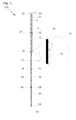
- Fig. 1 is a structural view illustrating an extended state of an electronic walking cane for the visually impaired according to an example of the present invention.
- Fig. 2 is a structural view illustrating a contracted state of an electronic walking cane for the visually impaired according to an example of the present invention.
- the electronic walking cane for the visually impaired of the present invention comprises:
- a first connection tube (12) which is inserted into upper section of the pillar tube (10) and secured within lower section thereof;
- a second connection tube (14) which is inserted into upper section of the first connection tube (12) and secured within lower section thereof;
- a third connection tube (16) which is inserted into upper section of the second connection tube (14) and secured within lower section thereof;
- a fourth connection tube (18) which is inserted into upper section of the third connection tube (16) and secured within lower section thereof, and within a lower end portion of which an antenna (20) is installed;
- a coiled cable (22) which is secured to an end portion of the pillar tube (10) and an end portion of the fourth tube (18), respectively and within which a plurality of coated wires are longitudinally arranged;
- An elastic member (24) which is inserted inside the coiled cable (22) and fastened to the end portion of the pillar tube (10) and the end portion of the fourth tube (18), respectively to prevent the twisting of the coiled tube (22);
- a first fastener (26) which is formed within the upper section of the pillar tube (10) to fasten one side of each of the coiled cable (22) and elastic member (24);
- a second fastener (28) which is formed within the lower section of the fourth connection tube (18) to fasten the other side of each of the coiled cable (22) and elastic member (24);
- a first cylindrical buffering element (32) which is installed within an end portion of the upper section of the first connection tube (12) to reduce noise generated when the coiled cable (22) and elastic member (24) strike the first connection tube (12) due to shaking of the walking cane;
- a second cylindrical buffering element (34) which is installed within an end portion of the upper section of the second connection tube (14) to reduce noise generated when the coiled cable (22) and elastic member (24) strike the second connection tube (14) due to shaking of the walking cane;
- a third cylindrical buffering element (36) which is installed within an end portion of the upper section of the third connection tube (16) to reduce noise generated when the coiled cable (22) and elastic member (24) strike the third connection tube (16) due to shaking of the walking cane;
- a fourth cylindrical buffering element (38) which is installed within an end portion of the upper part of the fourth connection tube (18) to reduce noise generated when the coiled cable (22) and elastic member (24) strike the fourth connection tube (18) due to shaking of the walking cane.
- a circuit board (not illustrated) is installed in the circuit mounting part (11) and a first insertion through hole (13) is formed for inserting the first connection tube (12).
- a second insertion through hole (15) is formed for inserting the second connection tube (14).
- a third insertion through hole (17) is formed for inserting the third connection tube (16).
- a fourth insertion through hole (19) is formed for inserting the fourth connection tube (18).
- the first fastener (26) for fastening one side of each of the coiled cable (22) and elastic member (24).
- the second fastener (28) for fastening the other side of each of the coiled cable (22) and elastic member (24).
- the coiled cable (22) with four coated electric wires longitudinally arranged within the cable and the elastic member (24) inserted inside the coiled cable (22) to prevent the twisting of the coiled cable (22) are fastened at the first and second fasteners (26, 28) so as not to be separated.
- the first cylindrical buffering element (32) is installed within an end portion of the upper section of the first connection tube (12) and reduces noise generated when the coiled cable (22) and elastic member (24) strike the first connection tube (12) due to shaking of the walking cane.
- the second cylindrical buffering element (34) is installed within an end portion of the upper section of the second connection tube (14) and reduces noise generated when the coiled cable (22) and elastic member (24) strike the second connection tube (14) due to shaking of the walking cane.
- the third cylindrical buffering element (36) which is installed within an end portion of the upper section of the third connection tube (16) and reduces noise generated when the coiled cable (22) and elastic member (24) strike the third connection tube (16) due to shaking of the walking cane.
- the fourth cylindrical buffering element (38) which is installed within an end portion of the upper section of the fourth connection tube (18) and reduces noise generated when the coiled cable (22) and elastic member (24) strike the fourth connection tube (18) due to shaking of the walking cane.
- sponge or cork material or styrofoam etc. may be used for example, and all of another buffering material may be also used.
- the first connection tube (12) is inserted from above the first insertion through hole (13) formed in the pillar tube (10) to a lower end portion thereof
- the second connection tube (14) is inserted from above the second insertion through hole (15) formed in the first connection tube (12) to a lower end portion thereof
- the third connection tube (16) is inserted from above the third insertion through hole (17) formed in the second connection tube (14) to a lower end portion thereof
- the fourth connection tube (18) is inserted from above the fourth insertion through hole (19) formed in the third connection tube (16) to a lower end portion thereof.
- the pillar tube (10) and the first to fourth connection tubes (12, 14, 16, 18) are formed in such a manner that they are gradually narrower from upper end portion to lower end portion, whereby upper end portion of the first connection tube (12) is caught and secured by lower end portion of the pillar tube (10), upper end portion of the second connection tube (14) is caught and secured by lower end portion of the first connection tube (12), upper end portion of the third connection tube (16) is caught and secured by lower end portion of the second connection tube (14), and upper end portion of the fourth connection tube (18) is caught and secured by lower end portion of the third connection tube (16).
- Two electric wires of the four coated electric wires arranged within the coiled cable (22) are "+" and "-" power supply wires and other two electric wires are used as signal transmission wire (Tx) and signal reception wire (Rx), and since the signal transmission wire (Tx) and signal reception wire (Rx) each require two electric wires, the "-" electric wire of the power supply wires is used in common in transmitting and receiving the signal.
- the electronic walking cane (100) is constructed in 5-stage by comprising the pillar tube (10) and the first to fourth connection tubes (12, 14, 16, 18), but may be constructed in conformance with the size of the walking cane to be carried along in the range from 2-stage to 8-stage.
- the electronic walking cane (100) for the visually impaired is used as described above and then is not used while its user is riding on the subway or bus or passenger car for example, if the first to fourth connection tubes (12, 14, 16, 18) are pushed in by applying force thereto, the electronic walking cane (100) is contracted, thus carried along while being put in user's bag etc..
- the first connection tube (12) is pushed into the pillar tube (10)
- the second connection tube (14) is pushed into the first connection tube (12)
- the third connection tube (16) is pushed into the second connection tube (14)
- the fourth connection tube (18) is pushed into the third connection tube (16), and as a result, the electronic walking cane becomes short as illustrated in Fig. 2 .
Landscapes
- Health & Medical Sciences (AREA)
- Epidemiology (AREA)
- Pain & Pain Management (AREA)
- Physical Education & Sports Medicine (AREA)
- Rehabilitation Therapy (AREA)
- Life Sciences & Earth Sciences (AREA)
- Animal Behavior & Ethology (AREA)
- General Health & Medical Sciences (AREA)
- Public Health (AREA)
- Veterinary Medicine (AREA)
- Rehabilitation Tools (AREA)
- Walking Sticks, Umbrellas, And Fans (AREA)
- Traffic Control Systems (AREA)
Description
- The present invention relates to an electronic walking cane for the visually impaired for recognizing RFID tags, more particularly, an electronic walking cane of telescopic type for the visually impaired for recognizing RFID tags which guides the visually impaired along a footpath by wirelessly detecting RFID tags embedded in Braille blocks with RFID reader provided in the walking cane when the visually impaired walks along the Braille blocks.
- In general, the visually impaired walks while perceiving location and danger by detecting protrusions of guide blocks on the ground with the walking cane. However, with such a way, the visually impaired may not know correct current location and advance direction to walk along, and when going to a certain place for the first time, has no choice but to obtain location information about the place from surrounding people. Therefore, for the place to go to for the first time, another guide person is needed.
- Currently, guide blocks are utilized by adding it among sidewalk blocks in order to guide the visually impaired to places requiring caution such as walk crossing, entrance door for getting on and off the subway, steps etc. or a specific location.
- However, such conventional guide blocks are made of material different from material for common blocks such as rubber, stainless steel, plastic, magnetic material etc., and the visually impaired detects the protrusions by his/her walking cane or foot. Furthermore, the visually impaired detects the guide blocks through sound or feeling by beating the blocks with the walking cane carried along or dragging the walking cane.
- The visually impaired detects the Braille blocks by feeling only with the shape of protrusions on the Braille blocks struck by the walking cane shaken about, and the type of message transmitted to the visually impaired by the shape in this way is mainly classified to three types and narrowly limited thereto, and actually, problems of slow detection speed, inconvenience and incorrectness are present in safely guiding the visually impaired to a desired place only with these messages when the visually impaired walks.
- For provision of information for the visually impaired, only acoustic information transmission using voice or sound etc. and tactile information transmission using Braille plate etc. are possible. The acoustic information transmission allows fast and correct transmission compared to the tactile information transmission. Many methods have been studied which enable the visually impaired to receive location information that the visually impaired can obtain by himself or herself.
- Meanwhile, as prior art relating to a walk guiding apparatus for the visually impaired, Korean Registered Utility Model No.
20-0203332 - In order to solve such a problem, Korean Published Patent Application No.
10-0647069 - According to a conventional walk guiding system for the visually impaired disclosed in Korean Registered Patent No.
10-0647069 - Common walking cane of telescopic type other than the electronic walking cane for the visually impaired is disclosed in Korean Registered Utility Model Publication No.
1998-6674 1998-6674 - The document
DE 37 11 469 A1 discloses an electronic walking cane for the visually impaired for recognizing induction loops inserted into pedestrian crossings, the electronic cane comprising:a pillar tube which is used as a handle and within which a circuit board is installed;a plurality of connection tubes which are sequentially inserted into one another;a coiled cable of which both end portions are fastened to a first fastener formed within an upper section of the pillar tube and to a second fastener of the lowest connection tube, respectively, and within which a plurality of coated electric wires are longitudinal arranged, wherein an inductive sensor is installed within a lower end portion of the lowest connection tube. - Furthermore, for collapsing the walking cane, if it is abutted at its lower section on the ground and then merely pressed by applying force to the walking cane, the released springs are contracted all together and at the same time the catching hook is caught on a securing device of a cap part, whereby the walking cane can be easily collapsed. This securing device is constructed such that the walking cane is prevented from being wrongly released as long as the user does not voluntarily push the release button of the walking cane in its collapsed state.
- By the way, such a common walking cane of telescopic type is not equipped with electric wire cable, so there is no problem in using it, but in recent, in case of mounting the RFID tags in the Braille blocks and mounting the RFID reader in the walking cane, since the antenna is mounted at lower end portion of the walking cane, the electric wire cable has to be connected up to a circuit board provided with the RFID reader.
- There are problems that it is difficult to connect the electric wire cable from the lower end portion of the walking cane to the circuit board provided with the RFID *other solutions of electronic walking cane have been disclosed also in documents
DE3711469A1 ,WO2006/042458A1 US5975712 A ,US4958651A reader at the upper end portion, and even though straight electric wire cable is connected, when collapsing or extending the walking cane, the electric wire cable is twisted due to rotation to thereby be broken or soldered portion is detached, as a result, the electronic walking cane cannot be used. - Due to such problems, the conventional electronic walking cane is not used in a telescopic manner, and instead a long walking cane of rod type formed in one piece is used, which has a problem that it is inconvenient for the user to store such a long walking cane when getting on the subway or bus.
- An object of the present invention is to an electronic walking cane for the visually impaired for recognizing RFID tags wherein when the electronic walking cane of walk guiding system utilizing the RFID tags is formed in a telescopic manner, the twisting of the electric wire cable is prevented and thus breaking of the electric wire cable or electric wire soldering portion of the electric wire cable can be prevented.
- Another object of the present invention is to an electronic walking cane for the visually impaired for recognizing RFID tags which can be collapsed to be stored in user's bag when getting on the subway or bus, thus is convenient to carry along.
- According to the invention, an electronic walking cane as claimed in claim 1 is provided.
- The electronic walking cane comprises a pillar tube which is used as a handle and within which a circuit board is installed; a plurality of connection tubes which are sequentially secured to another connection tube such that a first connection tube is inserted from a upper end portion of the pillar tube to a lower end portion thereof through a insertion through hole formed in the pillar tube to be secured within the lower end portion and other connection tubes are successively inserted from a upper end portion of a different connection tube to a lower end portion thereof to be secured within the lower end portion; a coiled cable of which both end portions are fastened to the pillar tube and the lowest connection tube of the plurality of connection tubes, respectively, and within which a plurality of coated electric wires are longitudinal arranged; an elastic member which is inserted inside the coiled cable and fastened to the pillar tube and the lowest one of the plurality of connection tubes, respectively to prevent the twisting of the coiled tube; a first fastener which is formed within the upper section of the pillar tube to fasten one side of each of the elastic member and coiled cable; a second fastener which is formed within the lower section of the lowest inserted connection tube of the plurality of connection tubes to fasten the other side of each of the elastic member and coiled cable; and a plurality of cylindrical buffering element which are installed within an end portion of the upper section of the plurality of connection tubes to reduce noise generated when the elastic member and coiled cable strike the plurality of connection tubes due to shaking of the walking cane.
- The electronic walking cane for the visually impaired of the present invention is characterized in that the plurality of connection tubes are formed in four-stage.
- The electronic walking cane for the visually impaired of the present invention is characterized in that the elastic member is a coil spring or rubber string.
- The electronic walking cane for the visually impaired of the present invention is characterized in that the pillar tube and the plurality of connection tubes are formed in such a manner that they are gradually narrower from upper end portion to lower end portion.
- The present invention has an advantage that when the visually impaired extends or contracts the electronic walking cane of telescopic type, the twisting of the electric wire cable is prevented and thus breaking of the electric wire cable or electric wire soldering portion of the electric wire cable can be prevented.
- The present invention has further advantage that the visually impaired can contract and then conveniently store the electronic walking cane of telescopic type when getting on the subway or bus.
-
-
Fig. 1 is a structural view illustrating an extended state of an electronic walking cane for the visually impaired according to an example of the present invention. -
Fig. 2 is a structural view illustrating a contracted state of an electronic walking cane for the visually impaired according to an example of the present invention. - Hereinafter, a preferred example of the present invention will be described in more detail with reference to the illustrated attached drawings. However, it should be understood that the present invention may be embodied in a plurality of different forms and is not limited to a described example. It should be noted that the example of the present invention described below is merely intended to explain the concept of the present invention to persons skilled in the art and detailed description will be omitted of functions and constructions known in the art which may unnecessarily obscure the gist of the present invention.
-
Fig. 1 is a structural view illustrating an extended state of an electronic walking cane for the visually impaired according to an example of the present invention. -
Fig. 2 is a structural view illustrating a contracted state of an electronic walking cane for the visually impaired according to an example of the present invention. - The electronic walking cane for the visually impaired of the present invention comprises:
- A pillar tube (10) to which a circuit mounting part (11) is joined;
- A first connection tube (12) which is inserted into upper section of the pillar tube (10) and secured within lower section thereof;
- A second connection tube (14) which is inserted into upper section of the first connection tube (12) and secured within lower section thereof;
- A third connection tube (16) which is inserted into upper section of the second connection tube (14) and secured within lower section thereof;
- A fourth connection tube (18) which is inserted into upper section of the third connection tube (16) and secured within lower section thereof, and within a lower end portion of which an antenna (20) is installed;
- A coiled cable (22) which is secured to an end portion of the pillar tube (10) and an end portion of the fourth tube (18), respectively and within which a plurality of coated wires are longitudinally arranged;
- An elastic member (24) which is inserted inside the coiled cable (22) and fastened to the end portion of the pillar tube (10) and the end portion of the fourth tube (18), respectively to prevent the twisting of the coiled tube (22);
- A first fastener (26) which is formed within the upper section of the pillar tube (10) to fasten one side of each of the coiled cable (22) and elastic member (24);
- A second fastener (28) which is formed within the lower section of the fourth connection tube (18) to fasten the other side of each of the coiled cable (22) and elastic member (24);
- A first cylindrical buffering element (32) which is installed within an end portion of the upper section of the first connection tube (12) to reduce noise generated when the coiled cable (22) and elastic member (24) strike the first connection tube (12) due to shaking of the walking cane;
- A second cylindrical buffering element (34) which is installed within an end portion of the upper section of the second connection tube (14) to reduce noise generated when the coiled cable (22) and elastic member (24) strike the second connection tube (14) due to shaking of the walking cane;
- A third cylindrical buffering element (36) which is installed within an end portion of the upper section of the third connection tube (16) to reduce noise generated when the coiled cable (22) and elastic member (24) strike the third connection tube (16) due to shaking of the walking cane; and
- A fourth cylindrical buffering element (38) which is installed within an end portion of the upper part of the fourth connection tube (18) to reduce noise generated when the coiled cable (22) and elastic member (24) strike the fourth connection tube (18) due to shaking of the walking cane.
- With reference to the above-mentioned
Figs. 1 and2 , a preferred electronic walking cane for the visually impaired of the present invention will be described in detail. - In the pillar tube (10), a circuit board (not illustrated) is installed in the circuit mounting part (11) and a first insertion through hole (13) is formed for inserting the first connection tube (12). In the first connection tube (12), a second insertion through hole (15) is formed for inserting the second connection tube (14). In the second connection tube (14), a third insertion through hole (17) is formed for inserting the third connection tube (16). In the third connection tube (16), a fourth insertion through hole (19) is formed for inserting the fourth connection tube (18).
- Then, installed within the upper section of the pillar tube (10) is the first fastener (26) for fastening one side of each of the coiled cable (22) and elastic member (24).
- Installed within the lower section of the fourth connection tube (18) is the second fastener (28) for fastening the other side of each of the coiled cable (22) and elastic member (24).
- When the pillar tube (10) and the first to fourth connection tubes (12, 14, 16, 18) are inserted into another and then secured, the coiled cable (22) with four coated electric wires longitudinally arranged within the cable and the elastic member (24) inserted inside the coiled cable (22) to prevent the twisting of the coiled cable (22) are fastened at the first and second fasteners (26, 28) so as not to be separated.
- Then, the first cylindrical buffering element (32) is installed within an end portion of the upper section of the first connection tube (12) and reduces noise generated when the coiled cable (22) and elastic member (24) strike the first connection tube (12) due to shaking of the walking cane.
- The second cylindrical buffering element (34) is installed within an end portion of the upper section of the second connection tube (14) and reduces noise generated when the coiled cable (22) and elastic member (24) strike the second connection tube (14) due to shaking of the walking cane.
- The third cylindrical buffering element (36) which is installed within an end portion of the upper section of the third connection tube (16) and reduces noise generated when the coiled cable (22) and elastic member (24) strike the third connection tube (16) due to shaking of the walking cane.
- The fourth cylindrical buffering element (38) which is installed within an end portion of the upper section of the fourth connection tube (18) and reduces noise generated when the coiled cable (22) and elastic member (24) strike the fourth connection tube (18) due to shaking of the walking cane.
- For material for the first to fourth buffering elements (32, 34, 36, 38), sponge or cork material or styrofoam etc. may be used for example, and all of another buffering material may be also used.
- For the electronic walking cane (100) for the visually impaired formed as described above, the first connection tube (12) is inserted from above the first insertion through hole (13) formed in the pillar tube (10) to a lower end portion thereof, the second connection tube (14) is inserted from above the second insertion through hole (15) formed in the first connection tube (12) to a lower end portion thereof, the third connection tube (16) is inserted from above the third insertion through hole (17) formed in the second connection tube (14) to a lower end portion thereof, and the fourth connection tube (18) is inserted from above the fourth insertion through hole (19) formed in the third connection tube (16) to a lower end portion thereof. The pillar tube (10) and the first to fourth connection tubes (12, 14, 16, 18) are formed in such a manner that they are gradually narrower from upper end portion to lower end portion, whereby upper end portion of the first connection tube (12) is caught and secured by lower end portion of the pillar tube (10), upper end portion of the second connection tube (14) is caught and secured by lower end portion of the first connection tube (12), upper end portion of the third connection tube (16) is caught and secured by lower end portion of the second connection tube (14), and upper end portion of the fourth connection tube (18) is caught and secured by lower end portion of the third connection tube (16). If the pillar tube (10) and the first to fourth connection tubes (12, 14, 16, 18) are pulled with all user's force, the upper section and lower section are tightly caught and secured, and hence tightening force of the upper and lower sections is larger than pulling force of the elastic member (24), so the electronic walking cane (100) can be kept in extended state.
- While the electronic walking cane (100) for the visually impaired thus assembled is used in the extended state, even if a specific one of the first to fourth connection tubes (12, 14, 16, 18) is rotated, the elastic member (24) and coiled cable (22) are returned to their original positions due to the elasticity of the elastic member (24) if the rotated one of the first to fourth connection tubes (12, 14, 16, 18) is released from the rotated state, whereby the coiled cable (22) is not twisted and at this time breaking of the four coated electric wires arranged within the coiled cable (22) is prevented or the coated electric wires prevent detachment of solder of coated wire formed on the antenna (20) and the circuit board arranged in the circuit mounting part (11). Coil spring or rubber string may be used for the elastic member (24), and in one example of the present invention, the use of coil spring is illustrated by example.
- Two electric wires of the four coated electric wires arranged within the coiled cable (22) are "+" and "-" power supply wires and other two electric wires are used as signal transmission wire (Tx) and signal reception wire (Rx), and since the signal transmission wire (Tx) and signal reception wire (Rx) each require two electric wires, the "-" electric wire of the power supply wires is used in common in transmitting and receiving the signal.
- In one example of the present invention, the electronic walking cane (100) is constructed in 5-stage by comprising the pillar tube (10) and the first to fourth connection tubes (12, 14, 16, 18), but may be constructed in conformance with the size of the walking cane to be carried along in the range from 2-stage to 8-stage.
- In case that the electronic walking cane (100) for the visually impaired is used as described above and then is not used while its user is riding on the subway or bus or passenger car for example, if the first to fourth connection tubes (12, 14, 16, 18) are pushed in by applying force thereto, the electronic walking cane (100) is contracted, thus carried along while being put in user's bag etc.. In order to contract the electronic walking cane (100) for the visually impaired, the first connection tube (12) is pushed into the pillar tube (10), the second connection tube (14) is pushed into the first connection tube (12), the third connection tube (16) is pushed into the second connection tube (14), and the fourth connection tube (18) is pushed into the third connection tube (16), and as a result, the electronic walking cane becomes short as illustrated in
Fig. 2 . - [56] Although the present invention has been described in detail with reference to the written specific example, it is obvious to persons skilled in the art that various alterations and modifications can be made within the scope of the appended claims.
Claims (3)
- An electronic walking cane (100) for the visually impaired for recognizing RFID tags, comprising:a pillar tube (10) which is used as a handle and within which a circuit board (11) is installed;a plurality of connection tubes (12, 14, 16, 18) which are sequentially inserted such that a first connection tube (12) is inserted from above a first insertion through hole formed in the pillar tube (10) to a lower end portion thereof, a second connection tube (14) is inserted from above a second insertion through hole formed in the first connection tube (12) to a lower end portion thereof, a third connection tube (16) is inserted from above a third insertion through hole formed in the second connection tube (14) to a lower end portion thereof, and a fourth connection tube (18) is inserted from above a fourth insertion through hole formed in the third connection tube (16) to a lower end portion thereof;an antenna (20) installed in the lower end portion of the fourth connection tube (18), the antenna (20) suitable to receive radio frequency signal from RFID tag;a coiled cable (22) of which both end portions are fastened to a first fastener (26) formed within an upper section of the pillar tube (10) and a second fastener (28) of the fourth connection tube (18) which is a lowest one of the plurality of connection tubes (12, 14, 16, 18), respectively, and within which a plurality of coated electric wires are longitudinal arranged to electrically connect the circuit board (11) to the antenna (20);an elastic member (24) which is inserted inside the coiled cable (22) and fastened to the pillar tube (10) and the second fastener (28) of the fourth tube (18) of the plurality of connection tubes (12, 14, 16, 18), respectively to prevent the twisting of the coiled cable (22) and pull the pillar tube (10) and the fourth connection tube (18) such that the plurality of connection tubes (12, 14, 16, 18) are not separated from each other; anda plurality of cylindrical buffering elements (32, 34, 36, 38) which are installed within an end portion of the upper section of the plurality of connection tubes (12, 14, 16, 18) to reduce noise generated when the elastic member (24) and coiled cable (22) strike the plurality of connection tubes (12, 14, 16, 18) due to shaking of the walking cane (100).
- The electronic walking cane (100) for the visually impaired for recognizing RFID tags according to claim 1, wherein the elastic member (24) is a coil spring or rubber string.
- The electronic walking cane (100) for the visually impaired for recognizing RFID tags according to any one of claims 1 to 2, wherein the pillar tube (10) and the plurality of connection tubes (12, 14, 16, 18) are formed in such a manner that they are gradually narrower from upper end portion to lower end portion.
Applications Claiming Priority (2)
| Application Number | Priority Date | Filing Date | Title |
|---|---|---|---|
| KR1020090133528A KR100998264B1 (en) | 2009-12-30 | 2009-12-30 | Visually impaired electronic cane to recognize RFID tags |
| PCT/KR2010/009215 WO2011081347A2 (en) | 2009-12-30 | 2010-12-22 | Electronic cane for the visually impaired for recognizing rfid tags |
Publications (3)
| Publication Number | Publication Date |
|---|---|
| EP2520267A2 EP2520267A2 (en) | 2012-11-07 |
| EP2520267A4 EP2520267A4 (en) | 2013-07-24 |
| EP2520267B1 true EP2520267B1 (en) | 2015-02-25 |
Family
ID=43512348
Family Applications (1)
| Application Number | Title | Priority Date | Filing Date |
|---|---|---|---|
| EP10841179.4A Not-in-force EP2520267B1 (en) | 2009-12-30 | 2010-12-22 | Electronic cane for the visually impaired for recognizing rfid tags |
Country Status (7)
| Country | Link |
|---|---|
| US (1) | US20120279539A1 (en) |
| EP (1) | EP2520267B1 (en) |
| JP (1) | JP5661800B2 (en) |
| KR (1) | KR100998264B1 (en) |
| CN (1) | CN102791238B (en) |
| MX (1) | MX2012007771A (en) |
| WO (1) | WO2011081347A2 (en) |
Families Citing this family (17)
| Publication number | Priority date | Publication date | Assignee | Title |
|---|---|---|---|---|
| KR100998265B1 (en) * | 2010-01-06 | 2010-12-03 | (주) 부성 리싸이클링 | Guiding system for guidance of pedestrians with blindness using RDF block and its method |
| KR101328121B1 (en) | 2011-04-12 | 2013-11-13 | 휴앤에스(주) | A subway station of guidance information system for the transportation disadvantaged |
| US9044374B1 (en) * | 2013-07-05 | 2015-06-02 | Leon E. Stimpson | Assisted walking device |
| KR101563339B1 (en) * | 2014-09-18 | 2015-10-26 | (주) 씨앤피 | Stick for blind |
| KR20160088983A (en) | 2015-01-16 | 2016-07-27 | 경북대학교 산학협력단 | Object Sensing Glove For Vision Impared People |
| US10186129B2 (en) * | 2015-04-09 | 2019-01-22 | Mary E. Hood | Locomotion safety and health assistant |
| KR101893374B1 (en) | 2017-02-14 | 2018-09-04 | 숭실대학교산학협력단 | A stick for the blind |
| KR101898582B1 (en) | 2017-02-14 | 2018-09-13 | 숭실대학교산학협력단 | A stick for the blind |
| CN107742771B (en) * | 2017-09-22 | 2019-09-17 | 上海卫星工程研究所 | The built-in satellite antenna being routed of radio-frequency cable can be achieved, arm assembly is unfolded |
| CN107945504A (en) * | 2017-12-08 | 2018-04-20 | 湖州师范学院 | Three wheeler guiding blind-man crossing street auxiliary device |
| KR102000505B1 (en) * | 2018-02-01 | 2019-07-16 | 호서대학교 산학협력단 | Smart stick for blinder |
| US11000442B2 (en) * | 2019-01-22 | 2021-05-11 | Victor Ramos | Mobility tool |
| KR20210085118A (en) | 2019-12-30 | 2021-07-08 | 이건명 | Walking assistance glove for vision impaired person |
| US12102588B2 (en) * | 2020-08-21 | 2024-10-01 | James L King | Powered walking assistance device with cane portion used as joystick controller |
| RU2768454C1 (en) * | 2021-01-25 | 2022-03-24 | Федеральное государственное бюджетное образовательное учреждение высшего образования Балтийский государственный технический университет "ВОЕНМЕХ" им. Д.Ф. Устинова (БГТУ "ВОЕНМЕХ") | Visually impaired walking stick |
| US20220330669A1 (en) * | 2021-04-14 | 2022-10-20 | Social Stick LLC | Social Distancing Apparatus |
| KR102828714B1 (en) | 2023-02-27 | 2025-07-07 | 한남대학교 산학협력단 | Electric stick for visually handicapped |
Family Cites Families (28)
| Publication number | Priority date | Publication date | Assignee | Title |
|---|---|---|---|---|
| US3987807A (en) * | 1975-11-10 | 1976-10-26 | Varnell Dennis H | Telescopic walking cane |
| JPH025780Y2 (en) * | 1986-06-06 | 1990-02-13 | ||
| DE3711469A1 (en) * | 1987-04-04 | 1988-10-20 | Stuehrenberg Rolf | Traffic signalling and guide device for blind persons |
| US4887625A (en) * | 1988-05-26 | 1989-12-19 | Americane, Inc. | Collapsible cane |
| US4958651A (en) * | 1989-05-09 | 1990-09-25 | Najm Emile G | Impact cushioning and avoiding device |
| US5197501A (en) * | 1991-09-26 | 1993-03-30 | Henry Ragatz | Multi-purpose cane |
| KR940023971U (en) * | 1993-04-28 | 1994-11-16 | 김동해 | Self-assembled wand with portable flashlight |
| JP2876305B2 (en) * | 1996-05-20 | 1999-03-31 | 株式会社サニー・シーリング | Guidance assistance system and device for visually impaired |
| US5973618A (en) * | 1996-09-25 | 1999-10-26 | Ellis; Christ G. | Intelligent walking stick |
| KR980006674U (en) | 1998-02-25 | 1998-04-30 | 백남칠 | Button-type automatic relaxation walking stick for the visually impaired |
| US5975712A (en) * | 1998-12-16 | 1999-11-02 | Shiao; Hsuan-Sen | Telescopic illuminating tool |
| KR200203332Y1 (en) | 2000-05-18 | 2000-11-15 | 주식회사우대기술단 | Walk guidance appliance for the blind |
| US6341614B1 (en) * | 2000-07-14 | 2002-01-29 | Robert E. Tucker | Collapsible cane |
| US6867697B2 (en) * | 2002-04-01 | 2005-03-15 | Pravin L. Nanayakkara | System for guiding the visually handicapped |
| DE20306698U1 (en) * | 2003-04-29 | 2003-07-31 | Bopp, Wolfgang, 55130 Mainz | truncheon |
| US7421933B1 (en) * | 2003-07-03 | 2008-09-09 | Frederick Thomas Pearson | Telescoping stun gun |
| JP2005052626A (en) * | 2003-07-18 | 2005-03-03 | Satoshi Suzuki | Walking stick for visually disabled person |
| JP2005230033A (en) * | 2004-02-17 | 2005-09-02 | Mitsuaki Osanai | Walking guide passage belt and walking stick |
| HK1066400A2 (en) * | 2004-10-20 | 2005-02-25 | 陈景辉 | A kind of multi-functional walking stick |
| US7267281B2 (en) * | 2004-11-23 | 2007-09-11 | Hopkins Billy D | Location, orientation, product and color identification system for the blind or visually impaired |
| US20060129308A1 (en) * | 2004-12-10 | 2006-06-15 | Lawrence Kates | Management and navigation system for the blind |
| KR100647069B1 (en) | 2005-02-25 | 2006-11-24 | 주식회사 에이티알앤디 | Walking guidance system for the visually impaired |
| KR100751819B1 (en) * | 2005-04-18 | 2007-08-29 | 엄현덕 | Directions system |
| JP2006345974A (en) * | 2005-06-14 | 2006-12-28 | Yukosha:Kk | Walking aid device for blind person |
| US7467746B2 (en) * | 2005-06-27 | 2008-12-23 | Pete Olmos | Magnetically activated guiding device and method |
| US20090032590A1 (en) * | 2007-08-02 | 2009-02-05 | Hopkins Billy D | Location, orientation, product and color identification apparatus, system and method for the blind or visually impaired |
| JP5113566B2 (en) * | 2008-03-13 | 2013-01-09 | 公益財団法人鉄道総合技術研究所 | Communication control method, guide cane, portable electronic device, and control program |
| US8523376B2 (en) * | 2010-12-06 | 2013-09-03 | John D. Motyka | Self-defense walking aid |
-
2009
- 2009-12-30 KR KR1020090133528A patent/KR100998264B1/en not_active Expired - Fee Related
-
2010
- 2010-12-22 JP JP2012546996A patent/JP5661800B2/en not_active Expired - Fee Related
- 2010-12-22 WO PCT/KR2010/009215 patent/WO2011081347A2/en not_active Ceased
- 2010-12-22 EP EP10841179.4A patent/EP2520267B1/en not_active Not-in-force
- 2010-12-22 CN CN201080060266.5A patent/CN102791238B/en not_active Expired - Fee Related
- 2010-12-22 US US13/520,335 patent/US20120279539A1/en not_active Abandoned
- 2010-12-22 MX MX2012007771A patent/MX2012007771A/en active IP Right Grant
Also Published As
| Publication number | Publication date |
|---|---|
| JP5661800B2 (en) | 2015-01-28 |
| CN102791238B (en) | 2014-08-06 |
| WO2011081347A3 (en) | 2011-11-24 |
| JP2013516210A (en) | 2013-05-13 |
| KR100998264B1 (en) | 2010-12-03 |
| EP2520267A2 (en) | 2012-11-07 |
| MX2012007771A (en) | 2012-09-28 |
| EP2520267A4 (en) | 2013-07-24 |
| WO2011081347A2 (en) | 2011-07-07 |
| US20120279539A1 (en) | 2012-11-08 |
| CN102791238A (en) | 2012-11-21 |
Similar Documents
| Publication | Publication Date | Title |
|---|---|---|
| EP2520267A2 (en) | Electronic cane for the visually impaired for recognizing rfid tags | |
| KR100998265B1 (en) | Guiding system for guidance of pedestrians with blindness using RDF block and its method | |
| US8786446B2 (en) | Position tracking apparatus for training animal | |
| US20090032590A1 (en) | Location, orientation, product and color identification apparatus, system and method for the blind or visually impaired | |
| KR20090020857A (en) | Walking guide device for the visually impaired | |
| JP2008282073A (en) | Pet guiding robot and pet guiding method | |
| KR101106076B1 (en) | Information system for visually impaired persons including emotional information and guidance method using the same | |
| KR101027240B1 (en) | Cane for the Blind | |
| KR100846299B1 (en) | Traffic information provision system and method | |
| KR20200077769A (en) | Traffic signal sound guidance system for visually impaired people | |
| KR20200093255A (en) | A Smart Stick Based On Ultrasonic Sensors | |
| JPH08191853A (en) | Guidance device by individual recognition | |
| KR20140104122A (en) | Guide apparatus for blind person | |
| JP7379489B2 (en) | Communication systems, processing equipment and belongings | |
| JP2006345974A (en) | Walking aid device for blind person | |
| KR100647069B1 (en) | Walking guidance system for the visually impaired | |
| KR101235585B1 (en) | Omni-directional apparatus and system for announce blind persons, method for announce using the same and recording medium thereof | |
| KR20200105034A (en) | Pedestrian signals for people with visual impairments using wireless communication system | |
| JP3879509B2 (en) | A foot-mounted communication device for guiding the visually impaired | |
| KR20190101789A (en) | Smart Cane for the Blind | |
| JP2005046607A (en) | Guided guidance system for the visually impaired | |
| KR200203332Y1 (en) | Walk guidance appliance for the blind | |
| KR200389015Y1 (en) | Sight obstacle personal use walk guidance system | |
| JPH07163628A (en) | Gait guidance system and sign and transmitter / receiver used therefor | |
| CN218685163U (en) | Blind guiding stick with connecting assembly |
Legal Events
| Date | Code | Title | Description |
|---|---|---|---|
| PUAI | Public reference made under article 153(3) epc to a published international application that has entered the european phase |
Free format text: ORIGINAL CODE: 0009012 |
|
| 17P | Request for examination filed |
Effective date: 20120705 |
|
| AK | Designated contracting states |
Kind code of ref document: A2 Designated state(s): AL AT BE BG CH CY CZ DE DK EE ES FI FR GB GR HR HU IE IS IT LI LT LU LV MC MK MT NL NO PL PT RO RS SE SI SK SM TR |
|
| DAX | Request for extension of the european patent (deleted) | ||
| A4 | Supplementary search report drawn up and despatched |
Effective date: 20130626 |
|
| RIC1 | Information provided on ipc code assigned before grant |
Ipc: A45B 19/08 20060101ALN20130620BHEP Ipc: A45B 3/00 20060101ALI20130620BHEP Ipc: A61H 3/06 20060101AFI20130620BHEP Ipc: A45B 9/00 20060101ALI20130620BHEP |
|
| RIC1 | Information provided on ipc code assigned before grant |
Ipc: A45B 3/00 20060101ALI20140811BHEP Ipc: A45B 9/00 20060101ALI20140811BHEP Ipc: A61H 3/06 20060101AFI20140811BHEP Ipc: A45B 19/08 20060101ALN20140811BHEP |
|
| GRAP | Despatch of communication of intention to grant a patent |
Free format text: ORIGINAL CODE: EPIDOSNIGR1 |
|
| INTG | Intention to grant announced |
Effective date: 20140919 |
|
| GRAS | Grant fee paid |
Free format text: ORIGINAL CODE: EPIDOSNIGR3 |
|
| GRAA | (expected) grant |
Free format text: ORIGINAL CODE: 0009210 |
|
| AK | Designated contracting states |
Kind code of ref document: B1 Designated state(s): AL AT BE BG CH CY CZ DE DK EE ES FI FR GB GR HR HU IE IS IT LI LT LU LV MC MK MT NL NO PL PT RO RS SE SI SK SM TR |
|
| REG | Reference to a national code |
Ref country code: GB Ref legal event code: FG4D |
|
| REG | Reference to a national code |
Ref country code: CH Ref legal event code: EP |
|
| REG | Reference to a national code |
Ref country code: IE Ref legal event code: FG4D |
|
| REG | Reference to a national code |
Ref country code: DE Ref legal event code: R096 Ref document number: 602010022725 Country of ref document: DE Effective date: 20150409 |
|
| REG | Reference to a national code |
Ref country code: AT Ref legal event code: REF Ref document number: 711298 Country of ref document: AT Kind code of ref document: T Effective date: 20150415 |
|
| REG | Reference to a national code |
Ref country code: NL Ref legal event code: VDEP Effective date: 20150225 |
|
| REG | Reference to a national code |
Ref country code: AT Ref legal event code: MK05 Ref document number: 711298 Country of ref document: AT Kind code of ref document: T Effective date: 20150225 |
|
| REG | Reference to a national code |
Ref country code: LT Ref legal event code: MG4D |
|
| PG25 | Lapsed in a contracting state [announced via postgrant information from national office to epo] |
Ref country code: LT Free format text: LAPSE BECAUSE OF FAILURE TO SUBMIT A TRANSLATION OF THE DESCRIPTION OR TO PAY THE FEE WITHIN THE PRESCRIBED TIME-LIMIT Effective date: 20150225 Ref country code: ES Free format text: LAPSE BECAUSE OF FAILURE TO SUBMIT A TRANSLATION OF THE DESCRIPTION OR TO PAY THE FEE WITHIN THE PRESCRIBED TIME-LIMIT Effective date: 20150225 Ref country code: SE Free format text: LAPSE BECAUSE OF FAILURE TO SUBMIT A TRANSLATION OF THE DESCRIPTION OR TO PAY THE FEE WITHIN THE PRESCRIBED TIME-LIMIT Effective date: 20150225 Ref country code: NO Free format text: LAPSE BECAUSE OF FAILURE TO SUBMIT A TRANSLATION OF THE DESCRIPTION OR TO PAY THE FEE WITHIN THE PRESCRIBED TIME-LIMIT Effective date: 20150525 Ref country code: FI Free format text: LAPSE BECAUSE OF FAILURE TO SUBMIT A TRANSLATION OF THE DESCRIPTION OR TO PAY THE FEE WITHIN THE PRESCRIBED TIME-LIMIT Effective date: 20150225 Ref country code: HR Free format text: LAPSE BECAUSE OF FAILURE TO SUBMIT A TRANSLATION OF THE DESCRIPTION OR TO PAY THE FEE WITHIN THE PRESCRIBED TIME-LIMIT Effective date: 20150225 |
|
| PG25 | Lapsed in a contracting state [announced via postgrant information from national office to epo] |
Ref country code: LV Free format text: LAPSE BECAUSE OF FAILURE TO SUBMIT A TRANSLATION OF THE DESCRIPTION OR TO PAY THE FEE WITHIN THE PRESCRIBED TIME-LIMIT Effective date: 20150225 Ref country code: IS Free format text: LAPSE BECAUSE OF FAILURE TO SUBMIT A TRANSLATION OF THE DESCRIPTION OR TO PAY THE FEE WITHIN THE PRESCRIBED TIME-LIMIT Effective date: 20150625 Ref country code: GR Free format text: LAPSE BECAUSE OF FAILURE TO SUBMIT A TRANSLATION OF THE DESCRIPTION OR TO PAY THE FEE WITHIN THE PRESCRIBED TIME-LIMIT Effective date: 20150526 Ref country code: AT Free format text: LAPSE BECAUSE OF FAILURE TO SUBMIT A TRANSLATION OF THE DESCRIPTION OR TO PAY THE FEE WITHIN THE PRESCRIBED TIME-LIMIT Effective date: 20150225 Ref country code: RS Free format text: LAPSE BECAUSE OF FAILURE TO SUBMIT A TRANSLATION OF THE DESCRIPTION OR TO PAY THE FEE WITHIN THE PRESCRIBED TIME-LIMIT Effective date: 20150225 |
|
| PG25 | Lapsed in a contracting state [announced via postgrant information from national office to epo] |
Ref country code: NL Free format text: LAPSE BECAUSE OF FAILURE TO SUBMIT A TRANSLATION OF THE DESCRIPTION OR TO PAY THE FEE WITHIN THE PRESCRIBED TIME-LIMIT Effective date: 20150225 |
|
| PG25 | Lapsed in a contracting state [announced via postgrant information from national office to epo] |
Ref country code: RO Free format text: LAPSE BECAUSE OF FAILURE TO SUBMIT A TRANSLATION OF THE DESCRIPTION OR TO PAY THE FEE WITHIN THE PRESCRIBED TIME-LIMIT Effective date: 20150225 Ref country code: SK Free format text: LAPSE BECAUSE OF FAILURE TO SUBMIT A TRANSLATION OF THE DESCRIPTION OR TO PAY THE FEE WITHIN THE PRESCRIBED TIME-LIMIT Effective date: 20150225 Ref country code: CZ Free format text: LAPSE BECAUSE OF FAILURE TO SUBMIT A TRANSLATION OF THE DESCRIPTION OR TO PAY THE FEE WITHIN THE PRESCRIBED TIME-LIMIT Effective date: 20150225 Ref country code: DK Free format text: LAPSE BECAUSE OF FAILURE TO SUBMIT A TRANSLATION OF THE DESCRIPTION OR TO PAY THE FEE WITHIN THE PRESCRIBED TIME-LIMIT Effective date: 20150225 Ref country code: EE Free format text: LAPSE BECAUSE OF FAILURE TO SUBMIT A TRANSLATION OF THE DESCRIPTION OR TO PAY THE FEE WITHIN THE PRESCRIBED TIME-LIMIT Effective date: 20150225 |
|
| REG | Reference to a national code |
Ref country code: DE Ref legal event code: R097 Ref document number: 602010022725 Country of ref document: DE |
|
| PG25 | Lapsed in a contracting state [announced via postgrant information from national office to epo] |
Ref country code: PL Free format text: LAPSE BECAUSE OF FAILURE TO SUBMIT A TRANSLATION OF THE DESCRIPTION OR TO PAY THE FEE WITHIN THE PRESCRIBED TIME-LIMIT Effective date: 20150225 |
|
| PG25 | Lapsed in a contracting state [announced via postgrant information from national office to epo] |
Ref country code: IT Free format text: LAPSE BECAUSE OF FAILURE TO SUBMIT A TRANSLATION OF THE DESCRIPTION OR TO PAY THE FEE WITHIN THE PRESCRIBED TIME-LIMIT Effective date: 20150225 |
|
| REG | Reference to a national code |
Ref country code: FR Ref legal event code: PLFP Year of fee payment: 6 |
|
| PLBE | No opposition filed within time limit |
Free format text: ORIGINAL CODE: 0009261 |
|
| STAA | Information on the status of an ep patent application or granted ep patent |
Free format text: STATUS: NO OPPOSITION FILED WITHIN TIME LIMIT |
|
| 26N | No opposition filed |
Effective date: 20151126 |
|
| PG25 | Lapsed in a contracting state [announced via postgrant information from national office to epo] |
Ref country code: SI Free format text: LAPSE BECAUSE OF FAILURE TO SUBMIT A TRANSLATION OF THE DESCRIPTION OR TO PAY THE FEE WITHIN THE PRESCRIBED TIME-LIMIT Effective date: 20150225 |
|
| PG25 | Lapsed in a contracting state [announced via postgrant information from national office to epo] |
Ref country code: BE Free format text: LAPSE BECAUSE OF FAILURE TO SUBMIT A TRANSLATION OF THE DESCRIPTION OR TO PAY THE FEE WITHIN THE PRESCRIBED TIME-LIMIT Effective date: 20150225 |
|
| PG25 | Lapsed in a contracting state [announced via postgrant information from national office to epo] |
Ref country code: MC Free format text: LAPSE BECAUSE OF FAILURE TO SUBMIT A TRANSLATION OF THE DESCRIPTION OR TO PAY THE FEE WITHIN THE PRESCRIBED TIME-LIMIT Effective date: 20150225 Ref country code: LU Free format text: LAPSE BECAUSE OF FAILURE TO SUBMIT A TRANSLATION OF THE DESCRIPTION OR TO PAY THE FEE WITHIN THE PRESCRIBED TIME-LIMIT Effective date: 20151222 |
|
| REG | Reference to a national code |
Ref country code: CH Ref legal event code: PL |
|
| REG | Reference to a national code |
Ref country code: IE Ref legal event code: MM4A |
|
| PG25 | Lapsed in a contracting state [announced via postgrant information from national office to epo] |
Ref country code: LI Free format text: LAPSE BECAUSE OF NON-PAYMENT OF DUE FEES Effective date: 20151231 Ref country code: CH Free format text: LAPSE BECAUSE OF NON-PAYMENT OF DUE FEES Effective date: 20151231 Ref country code: IE Free format text: LAPSE BECAUSE OF NON-PAYMENT OF DUE FEES Effective date: 20151222 |
|
| REG | Reference to a national code |
Ref country code: FR Ref legal event code: PLFP Year of fee payment: 7 |
|
| PGFP | Annual fee paid to national office [announced via postgrant information from national office to epo] |
Ref country code: GB Payment date: 20161215 Year of fee payment: 7 |
|
| PGFP | Annual fee paid to national office [announced via postgrant information from national office to epo] |
Ref country code: FR Payment date: 20161215 Year of fee payment: 7 |
|
| PGFP | Annual fee paid to national office [announced via postgrant information from national office to epo] |
Ref country code: DE Payment date: 20170228 Year of fee payment: 7 |
|
| PG25 | Lapsed in a contracting state [announced via postgrant information from national office to epo] |
Ref country code: SM Free format text: LAPSE BECAUSE OF FAILURE TO SUBMIT A TRANSLATION OF THE DESCRIPTION OR TO PAY THE FEE WITHIN THE PRESCRIBED TIME-LIMIT Effective date: 20150225 Ref country code: BG Free format text: LAPSE BECAUSE OF FAILURE TO SUBMIT A TRANSLATION OF THE DESCRIPTION OR TO PAY THE FEE WITHIN THE PRESCRIBED TIME-LIMIT Effective date: 20150225 Ref country code: HU Free format text: LAPSE BECAUSE OF FAILURE TO SUBMIT A TRANSLATION OF THE DESCRIPTION OR TO PAY THE FEE WITHIN THE PRESCRIBED TIME-LIMIT; INVALID AB INITIO Effective date: 20101222 |
|
| PG25 | Lapsed in a contracting state [announced via postgrant information from national office to epo] |
Ref country code: CY Free format text: LAPSE BECAUSE OF FAILURE TO SUBMIT A TRANSLATION OF THE DESCRIPTION OR TO PAY THE FEE WITHIN THE PRESCRIBED TIME-LIMIT Effective date: 20150225 |
|
| PG25 | Lapsed in a contracting state [announced via postgrant information from national office to epo] |
Ref country code: MT Free format text: LAPSE BECAUSE OF FAILURE TO SUBMIT A TRANSLATION OF THE DESCRIPTION OR TO PAY THE FEE WITHIN THE PRESCRIBED TIME-LIMIT Effective date: 20150225 |
|
| PG25 | Lapsed in a contracting state [announced via postgrant information from national office to epo] |
Ref country code: MK Free format text: LAPSE BECAUSE OF FAILURE TO SUBMIT A TRANSLATION OF THE DESCRIPTION OR TO PAY THE FEE WITHIN THE PRESCRIBED TIME-LIMIT Effective date: 20150225 Ref country code: PT Free format text: LAPSE BECAUSE OF FAILURE TO SUBMIT A TRANSLATION OF THE DESCRIPTION OR TO PAY THE FEE WITHIN THE PRESCRIBED TIME-LIMIT Effective date: 20150225 Ref country code: TR Free format text: LAPSE BECAUSE OF FAILURE TO SUBMIT A TRANSLATION OF THE DESCRIPTION OR TO PAY THE FEE WITHIN THE PRESCRIBED TIME-LIMIT Effective date: 20150225 |
|
| REG | Reference to a national code |
Ref country code: DE Ref legal event code: R119 Ref document number: 602010022725 Country of ref document: DE |
|
| GBPC | Gb: european patent ceased through non-payment of renewal fee |
Effective date: 20171222 |
|
| REG | Reference to a national code |
Ref country code: FR Ref legal event code: ST Effective date: 20180831 |
|
| PG25 | Lapsed in a contracting state [announced via postgrant information from national office to epo] |
Ref country code: DE Free format text: LAPSE BECAUSE OF NON-PAYMENT OF DUE FEES Effective date: 20180703 Ref country code: FR Free format text: LAPSE BECAUSE OF NON-PAYMENT OF DUE FEES Effective date: 20180102 Ref country code: AL Free format text: LAPSE BECAUSE OF FAILURE TO SUBMIT A TRANSLATION OF THE DESCRIPTION OR TO PAY THE FEE WITHIN THE PRESCRIBED TIME-LIMIT Effective date: 20150225 |
|
| PG25 | Lapsed in a contracting state [announced via postgrant information from national office to epo] |
Ref country code: GB Free format text: LAPSE BECAUSE OF NON-PAYMENT OF DUE FEES Effective date: 20171222 |