EP2519050A1 - Station mobile, station de base sans fil, et procédé de communication mobile - Google Patents
Station mobile, station de base sans fil, et procédé de communication mobile Download PDFInfo
- Publication number
- EP2519050A1 EP2519050A1 EP10839415A EP10839415A EP2519050A1 EP 2519050 A1 EP2519050 A1 EP 2519050A1 EP 10839415 A EP10839415 A EP 10839415A EP 10839415 A EP10839415 A EP 10839415A EP 2519050 A1 EP2519050 A1 EP 2519050A1
- Authority
- EP
- European Patent Office
- Prior art keywords
- carrier
- control signal
- assignment
- downlink
- downlink control
- Prior art date
- Legal status (The legal status is an assumption and is not a legal conclusion. Google has not performed a legal analysis and makes no representation as to the accuracy of the status listed.)
- Withdrawn
Links
Images


Classifications
-
- H—ELECTRICITY
- H04—ELECTRIC COMMUNICATION TECHNIQUE
- H04L—TRANSMISSION OF DIGITAL INFORMATION, e.g. TELEGRAPHIC COMMUNICATION
- H04L5/00—Arrangements affording multiple use of the transmission path
- H04L5/0001—Arrangements for dividing the transmission path
- H04L5/0003—Two-dimensional division
- H04L5/0005—Time-frequency
- H04L5/0007—Time-frequency the frequencies being orthogonal, e.g. OFDM(A), DMT
- H04L5/001—Time-frequency the frequencies being orthogonal, e.g. OFDM(A), DMT the frequencies being arranged in component carriers
-
- H—ELECTRICITY
- H04—ELECTRIC COMMUNICATION TECHNIQUE
- H04L—TRANSMISSION OF DIGITAL INFORMATION, e.g. TELEGRAPHIC COMMUNICATION
- H04L5/00—Arrangements affording multiple use of the transmission path
- H04L5/0091—Signaling for the administration of the divided path
- H04L5/0096—Indication of changes in allocation
- H04L5/0098—Signalling of the activation or deactivation of component carriers, subcarriers or frequency bands
-
- H—ELECTRICITY
- H04—ELECTRIC COMMUNICATION TECHNIQUE
- H04W—WIRELESS COMMUNICATION NETWORKS
- H04W72/00—Local resource management
- H04W72/20—Control channels or signalling for resource management
- H04W72/23—Control channels or signalling for resource management in the downlink direction of a wireless link, i.e. towards a terminal
Definitions
- the present invention relates to a mobile communication technology field, and particularly, to a mobile station, a radio base station, and a mobile communication method in a mobile communication system using the next generation mobile communication technology.
- a communication scheme which is the next generation of a WCDMA (Wideband Code Division Multiplexing Access) scheme, an HSDPA (High-Speed Downlink Pcket Access) scheme, an HSUPA (High-Speed Uplink Pcket Access) scheme and the like, that is, an LTE (Long Term Evolution) scheme has been discussed in the 3GPP, which is a group aiming to standardize the WCDMA, and the specification work is under progress.
- WCDMA Wideband Code Division Multiplexing Access
- HSDPA High-Speed Downlink Pcket Access
- HSUPA High-Speed Uplink Pcket Access
- LTE Long Term Evolution
- an OFDMA Orthogonal Frequency Division Multiplexing Access
- SC-FDMA Single-Carrier Frequency Division Multiple Access
- the OFDMA scheme denotes a multicarrier transmission scheme in which a frequency band is divided into a plurality of narrow frequency bands (sub-carriers), and data is loaded on each sub-carrier for transmission.
- sub-carriers are densely arranged on the frequency axis while being orthogonal to one another, so that high-rate transmission is achieved, resulting in the improvement of frequency use efficiency.
- the SC-FDMA scheme denotes a single carrier transmission scheme in which a frequency band is divided for each terminal, and transmission is performed using different frequency bands among a plurality of mobile stations UEs (User Equipments).
- UEs User Equipments
- the SC-FDMA scheme since it is possible to easily and efficiently reduce interference among the mobile stations UEs and suppress variation in transmission power, the SC-FDMA scheme is advantageous in terms of low power consumption of a mobile station UE, expansion of coverage and the like.
- the LTE scheme corresponds to a system in which a plurality of mobile stations UEs share one or two or more physical channels in an uplink and a downlink, and perform communication.
- the channel shared by the plurality of mobile stations UEs is generally called a “shared channel", and in the LTE scheme, the channel is "Physical Uplink Shared Channel (PUSCH)" in an uplink, and is “Physical Downlink Shared Channel (PDSCH)” in a downlink.
- PUSCH Physical Uplink Shared Channel
- PDSCH Physical Downlink Shared Channel
- the shared channel is UL-SCH (Uplink Shared Channel) in an uplink, and is DL-SCH (Downlink Shared Channel) in a downlink.
- UL-SCH Uplink Shared Channel
- DL-SCH Downlink Shared Channel
- a control channel used for the signaling is called "PDCCH (Physical Downlink Control Channel)" or "DL L1/L2 Control Channel (Downlink L1/L2 Control Channel)”.
- PDCH Physical Downlink Control Channel
- DL L1/L2 Control Channel Downlink L1/L2 Control Channel
- the above-mentioned process for selecting the mobile station UE to which the shared channel is to be assigned in each sub-frame is generally called “scheduling".
- the above-mentioned expression indicating the "the shared channel is to be assigned” may be expressed as the "a radio resource for the shared channel is to be assigned”.
- Information on the physical downlink control channel includes "Downlink Scheduling Information” or "Uplink Scheduling Grant”.
- the "Downlink Scheduling Information” includes assignment information of a downlink resource block related to a downlink shared channel, UE-ID, the number of streams, information on a precoding vector, a data size, a modulation scheme, and information on HARQ (hybrid automatic repeat request).
- Uplink Scheduling Grant includes assignment information of an uplink resource block related to an uplink shared channel, UE-ID, a data size, a modulation scheme, uplink transmission power information, and information on a demodulation reference signal in Uplink MIMO.
- Downlink Scheduling Information or "Uplink Scheduling Grant” may also be collectively called “DCI (Downlink Control Information)”.
- the "Carrier aggregation” represents that communication is simultaneously performed using a plurality of carriers.
- the mobile station UE when the "Carrier aggregation" is performed in the uplink, since the mobile station UE performs transmission using a plurality of carriers different from one another in each "Component Carrier", the mobile station UE transmits an uplink signal using the plurality of carriers.
- the mobile station UE receives a downlink signal using the plurality of carriers.
- 6 RBs, 15 RBs, 25 RBs, 50 RBs, 75 RBs, and 100 RBs have been defined as a system bandwidth (a channel bandwidth).
- 1 RB Resource Block
- Component Carrier in the LTE-advanced scheme corresponds to one carrier of the LTE, and a bandwidth of the “Component Carrier” has been proposed to be equal to the above-mentioned channel bandwidth.
- Carrier Segment or “Extension Carrier”
- Extension Carrier in order to reduce overhead due to the synchronization signal or the common channel signal such as broadcast information, it has been discussed that the common channel signal is not transmitted.
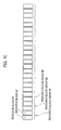
- a size when the number of resource blocks is grouped is decided according to the number of the resource blocks in a system bandwidth as illustrated in Fig. 9 , and the resource blocks are assigned to each group of the grouped resource blocks.
- a resource block size is "2".
- 1 bit is defined for each resource group including two resource blocks, and whether there is resource assignment is designated based on the value of the 1 bit.
- bits #1, #2, #3, ... are defined for resource block groups #1, #2, #3, ... to designate the assignment or non-assignment of a resource block, and the assignment or non-assignment of a resource is designated according to "0" or "1" which is a value of the bits #1, #2, #3,
- a resource block size is "3" as illustrated in Fig. 9 .
- resource assignment is performed in each resource block group grouped by two resource blocks.
- resource assignment is performed in each resource block group grouped by three resource blocks.
- the mobile station UE not supporting the "Carrier Segment” may be a mobile station UE having not Capability of the LTE-advanced scheme but only Capability of the LTE scheme.
- the present invention has been achieved in view of the above-described problems, and an object thereof is to provide a mobile station, a radio base station, and a mobile communication method, by which it is possible to achieve system efficiency by efficiently assigning a resource in "Carrier Segment” or “Extension Carrier” added in order to effectively use a frequency resource.
- a first characteristic of the present embodiment is summarized in that a mobile station, which is configured to perform downlink communication with respect to a radio base station using a normal carrier and an additional carrier, comprising, a control signal reception unit configured to receive a downlink control signal for notifying transmission of downlink data from the radio base station; and a reception unit configured to receive the downlink data based on the received downlink control signal, in which the downlink control signal includes a bit indicating assignment or non-assignment of the additional carrier, in addition to resource assignment information of the normal carrier.
- a second characteristic of the present embodiment is summarized in that a mobile station, which is configured to perform uplink communication with respect to a radio base station using a normal carrier and an additional carrier, comprising, a control signal reception unit configured to receive a downlink control signal for instructing transmission of uplink data from the radio base station; and a transmission unit configured to transmit the uplink data based on the received downlink control signal, in which the downlink control signal includes a bit indicating assignment or non-assignment of the additional carrier, in addition to resource assignment information of the normal carrier.
- a third characteristic of the present embodiment is summarized in that a radio base station, which is configured to perform downlink communication with respect to a mobile station using a normal carrier and an additional carrier, comprising, a control signal transmission unit configured to transmit a downlink control signal for notifying transmission of downlink data to the mobile station, and a transmission unit configured to transmit the downlink data, in which the downlink control signal includes a bit indicating assignment or non-assignment of the additional carrier, in addition to resource assignment information of the normal carrier.
- a fourth characteristic of the present embodiment is summarized in that a radio base station, which is configured to perform uplink communication with respect to a mobile station using a normal carrier and an additional carrier, comprising:
- a fifth characteristic of the present embodiment is summarized in that a mobile communication method in a mobile station, which performs downlink communication with respect to a radio base station using a normal carrier and an additional carrier, comprising, a step of receiving a downlink control signal for notifying transmission of downlink data from the radio base station, and a step of receiving the downlink data based on the received downlink control signal, in which the downlink control signal includes a bit indicating assignment or non-assignment of the additional carrier, in addition to resource assignment information of the normal carrier.
- a sixth characteristic of the present embodiment is summarized in that a mobile communication method in a mobile station, which performs uplink communication with respect to a radio base station using a normal carrier and an additional carrier, comprising, a step of transmitting a downlink control signal for instructing transmission of uplink data from the radio base station, and a step of transmitting the uplink data based on the received downlink control signal, in which the downlink control signal includes a bit indicating assignment or non-assignment of the additional carrier, in addition to resource assignment information of the normal carrier.
- Carrier Segment or “Extension Carrier” is defined as a “small carrier added in order to effectively use a frequency resource”, and will be called “Carrier Segment/Extension Carrier” as a general name.
- Carrier Segment/Extension Carrier may be “Carrier Segment” or may be “Extension Carrier”.
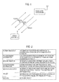
- a mobile station UE and a radio base station eNB With reference to Fig. 1 , the mobile communication system including a mobile station UE and a radio base station eNB according to the present embodiment will be described.
- the mobile communication system is a system employing "Evolved UTRA and UTRAN (another name: Long Term Evolution or Supper 3G)" scheme or an LTE-Advanced scheme.
- the mobile communication system includes a radio base station eNB and a mobile station UE communicating with the radio base station eNB.
- an "OFDMA (Orthogonal Frequency Division Multiplexing Access) scheme” is applied to a downlink
- SC-FDMA (Single-Carrier Frequency Division Multiple Access) scheme is applied to an uplink.
- the OFDMA scheme is a multicarrier transmission scheme in which a frequency band is divided into a plurality of narrow frequency bands (sub-carriers) and data is mapped to each sub-carrier, so that communication is performed.
- the SC-FDMA scheme is a single carrier transmission scheme in which a frequency band is divided for each mobile station UE, and a plurality of mobile stations UEs use frequency bands different from one another, so that interference among the mobile stations UEs is reduced.
- Carrier Aggregation is configured to be performed.
- the "Component Carrier” corresponds to one system carrier in an LTE scheme. That is, in the LTE scheme, communication is performed using one "Component Carrier", but in an LTE-Advanced scheme, communication may be performed using two or more "Component Carriers".
- a "physical downlink shared channel (PDSCH)” and a “physical downlink control channel (PDCCH)” shared by each mobile station UE are used.
- the "physical downlink shared channel (PDSCH)" is used to transmit downlink user data (downlink data), that is, a normal data signal.
- the data signal includes best effort type packet data, streaming type packet data, a control signal, and the like.
- the best effort type packet data includes packet data for transmitting/receiving an e-mail, packet data for Web browsing, and the like.
- the data signal may include a sound signal and the like by VoIP and the like.
- control signal for example, corresponds to an RRC message, and may correspond to DCCH (Dedicated Control Channel) as a logical channel.
- DCCH Dedicated Control Channel
- the PDCCH is used to notify information (that is, downlink scheduling information) on an ID of a mobile station UE performing communication using the PDSCH or a transport format of user data, information (that is, an uplink scheduling grant) on an ID of a mobile station UE performing communication using PUSCH (Physical Uplink Shared Channel) or a transport format of user data, and the like.
- information that is, downlink scheduling information
- PUSCH Physical Uplink Shared Channel
- the PDCCH may also be called “Downlink L1/L2 Control Channel”. Furthermore, the "downlink scheduling information” or the “uplink scheduling grant” may also be collectively called “downlink control information (DCI)”.
- DCI downlink control information
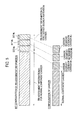
- Fig. 2 illustrates an example of information elements included in the downlink scheduling information.
- the downlink scheduling information may include information elements such as "Format Indicator”, "RB assignment information”, “MCS information”, “HARQ process information”, "New Data Indicator”, “TPC bit”, or "RNTI/CRC”.
- information elements are for illustrative purposes only, other information elements may also be included or only a part of the information elements may also be included.
- the "Format Indicator” denotes information indicating whether the PDCCH is information for an uplink or information for a downlink.
- the "RB assignment information” denotes information indicating assignment information of a resource block regarding a downlink signal designated by the PDCCH.
- the "MCS information” denotes information indicating information about MCS regarding the downlink signal designated by the PDCCH.
- the "HARQ process information” denotes information indicating information on an HARQ process of the downlink signal designated by the PDCCH.
- the "New Data Indicator” denotes information indicating whether the downlink signal designated by the PDCCH is newly transmitted or is retransmitted.
- the "TPC bit” denotes information for transmission power control of an uplink control signal designated by the PDCCH.
- the "RNTI/CRC” denotes a UE ID and a CRC bit.
- the "RB assignment information” includes “RB assignment information” (part A illustrated in Fig. 3 ) for the normal “Component Carrier”, and “RB assignment information” (part B illustrated in Fig. 2 ) for the "Carrier Segment/Extension Carrier”.
- the "RB assignment information” (part A illustrated in Fig. 3 ) for the normal “Component Carrier", for example, may be equal to "RB (Resource Block) assignment information” defined in "7.1.6 Resource allocation” of TS 36.213 of the 3GPP.
- RB assignment information (part B illustrated in Fig. 3 ) for the "Carrier Segment/Extension Carrier”
- resource assignment may be instructed by the bits.
- bit #a, bit #b, and bit #c may be defined, respectively, and assignment of the "Carrier Segment/Extension Carrier #A", the “Carrier Segment/Extension Carrier #B", and the “Carrier Segment/Extension Carrier #C” may be instructed by the bit #a, the bit #b, and the bit #c, respectively.
- the bit #a 0
- there is resource assignment in the "Carrier Segment/Extension Carrier #A” that is, a PDSCH signal is transmitted in the 6 RBs of the "Carrier Segment/Extension Carrier #A”.
- the RBs may be divided into two, that is, 3 RBs and 3 RBs, and 1 bit may be defined for each of the 3 RBs and the 3 RBs. In this case, it is possible to assign RBs more finely and flexibly.
- the number of the "Carrier Segment/Extension Carriers” is “3".
- the number of the "Carrier Segment/Extension Carriers” may be other numbers other than “3”.
- Fig. 4 illustrates an example of information elements included in the uplink scheduling grant.
- the uplink scheduling grant may include information elements such as "Format Indicator”, “Hopping flag”, “RB assignment information”, “MCS information”, “New Data Indicator”, “TPC bit”, “Cyclic shift for DMRS", “CQI request” or "RNTI/CRC”.
- information elements such as "Format Indicator”, “Hopping flag”, "RB assignment information”, “MCS information”, “New Data Indicator”, “TPC bit”, “Cyclic shift for DMRS", “CQI request” or "RNTI/CRC”.
- the information elements are for illustrative purposes only, other information elements may also be included or only a part of the information elements may also be included.
- the "Format Indicator” denotes information indicating whether the PDCCH is information for an uplink or information for a downlink.
- the "Hopping flag” denotes information indicating whether hoppling is applied to an uplink signal, the transmission of which is instructed by the PDCCH.
- the "RB assignment information” denotes information indicating assignment information of a resource block regarding the uplink signal, the transmission of which is instructed by the PDCCH.
- the "MCS information” denotes information indicating information about MCS regarding the uplink signal, the transmission of which is instructed by the PDCCH.
- the "New Data Indicator” denotes information indicating whether the uplink signal is newly transmitted or is retransmitted, the transmission of the uplink signal being instructed by the PDCCH.
- the "TPC bit” denotes information for uplink transmission power control of the uplink signal designated by the PDCCH.
- Cyclic shift for DMRS denotes information regarding Cyclic shift of Demodulation Reference signal of the uplink signal designated by the PDCCH.
- the "CQI request” denotes information instructing that CQI is transmitted in an uplink.
- the "RNTI/CRC” denotes a UE ID and a CRC bit.
- the "RB assignment information” includes “RB assignment information (part A illustrated in Fig. 5 )" for the normal “Component Carrier”, and “RB assignment information (part B illustrated in Fig. 5 )" for the "Carrier Segment/Extension Carrier”.
- the "RB assignment information (part A illustrated in Fig. 5 )" for the normal “Component Carrier”, for example, may be equal to "RB (Resource Block) assignment information” defined in "8.1 Resource Allocation for PDCCH DCI Format 0" of TS 36.213 of the 3GPP.
- RB assignment information (part B illustrated in Fig. 5 )" for the "Carrier Segment/Extension Carrier"
- a predetermined number of bits may be defined for one "Carrier Segment/Extension Carrier”, and resource assignment may be instructed by the bits.
- the RBs may be divided into two, that is, 3 RBs and 3 RBs, and 1 bit may be defined for each of the 3 RBs and the 3 RBs. In this case, it is possible to assign RBs more finely and flexibly.
- the number of the "Carrier Segment/Extension Carriers” is “3".
- the number of the "Carrier Segment/Extension Carriers” may be other numbers other than “3”.
- the PUSCH and the PUCCH shared and used by each mobile station UE are used.
- the PUSCH is used to transmit uplink user data (uplink data), that is, a normal data signal.
- the PUCCH is used to transmit downlink quality information (CQI: Channel Quality Indicator), which is to be used in a scheduling process of the PDSCH or AMCS (Adaptive Modulation and Coding Scheme), and transmission acknowledgement information (Acknowledgement Information) of the PDSCH.
- CQI Channel Quality Indicator
- AMCS Adaptive Modulation and Coding Scheme
- Acknowledgement Information transmission acknowledgement information
- the downlink quality information may also be called CSI (Channel State Indicator) which is an indicator which groups together of CQI, PMI (Pre-coding Matrix Indicator), or RI (Rank Indicator).
- CSI Channel State Indicator
- PMI Pre-coding Matrix Indicator
- RI Rank Indicator
- the content of the transmission acknowledgement information is expressed by any one of a positive response (ACK: Acknowledgement) indicating that a transmission signal has been properly received, and a negative response (NACK: Negative Acknowledgement) indicating that the transmission signal has not been properly received.
- ACK Acknowledgement
- NACK Negative Acknowledgement
- the CQI or the transmission acknowledgement information may also be multiplexed to the PUSCH for transmission.
- the mobile station UE includes a control signal reception unit 11, a transmission unit 12, and a reception unit 13.
- the control signal reception unit 11 is configured to receive a plurality of downlink control signals for instructing the transmission of uplink data (specifically, uplink data to be transmitted through the PUSCH), or the reception of downlink data (specifically, downlink data to be transmitted through the PDSCH).
- control signal reception unit 11 may be configured to receive an "uplink scheduling grant” or “downlink scheduling information" through the PDCCH as the downlink control signal.
- the downlink control signal for example, includes the information elements illustrated in Fig. 4 as parameters.
- the information element includes the "RB assignment information" described in Fig. 5 .
- the downlink control signal for example, includes the information elements illustrated in Fig. 2 as parameters.
- the information element includes the "RB assignment information" described in Fig. 3 .
- the transmission unit 12 is configured to transmit uplink data to the radio base station eNB based on the downlink control signal received in the control signal reception unit 11.
- the transmission unit 12 may be configured to transmit the uplink data using the "Carrier Segment/Extension Carrier #A", in addition to a resource block designated by the normal "Component Carrier".
- the transmission unit 12 may be configured to transmit the uplink data using only the "Carrier Segment/Extension Carrier #A".
- the reception unit 13 is configured to receive downlink data from the radio base station eNB based on the downlink control signal received in the control signal reception unit 11.
- the reception unit 13 may be configured to receive downlink data using the "Carrier Segment/Extension Carrier #A", in addition to a resource block designated by the normal "Component Carrier".
- the reception unit 13 may be configured to receive the downlink data using only the "Carrier Segment/Extension Carrier #A".
- the radio base station eNB includes a control signal transmission unit 21, a reception unit 22, and a transmission unit 23.
- the control signal transmission unit 21 is configured to transmit one or a plurality of downlink control signals for instructing the transmission of uplink data (specifically, uplink data to be transmitted through the PUSCH), or for notifying the transmission of downlink data (specifically, downlink data to be transmitted through the PDSCH).
- control signal transmission unit 21 may be configured to transmit an "uplink scheduling grant” or “downlink scheduling information" through the PDCCH as the downlink control signal.
- the downlink control signal for example, includes the information elements illustrated in Fig. 4 as parameters.
- the information element includes the "RB assignment information" described in Fig. 5 .
- the downlink control signal for example, includes the information elements illustrated in Fig. 2 as parameters.
- the information element includes the "RB assignment information" described in Fig. 3 .
- the reception unit 22 is configured to receive uplink data transmitted by the mobile station UE using a plurality of carriers based on one or plurality of downlink control signals.
- the reception unit 22 may be configured to receive uplink data using the "Carrier Segment/Extension Carrier #A", in addition to a resource block designated by the normal "Component Carrier".
- the reception unit 22 may be configured to receive the uplink data using only the "Carrier Segment/Extension Carrier #A".
- the transmission unit 23 is configured to transmit downlink data to the mobile station UE using one or a plurality of carriers designated by the plurality of downlink control signals.
- the transmission unit 23 may be configured to transmit the downlink data using the "Carrier Segment/Extension Carrier #A", in addition to a resource block designated by the normal "Component Carrier".
- the transmission unit 22 may be configured to transmit the downlink data using only the "Carrier Segment/Extension Carrier #A".
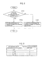
- step S101 the mobile station UE determines whether the "bit #a" has a value of "0", which indicates assignment information regarding the "Carrier Segment/Extension Carrier #A" in the "RB assignment information" included in the downlink scheduling information.
- step S101: YES When the "bit #a" has a value of "0" (step S101: YES), the present operation proceeds to step S102. In another case (step S101: NO), the present operation proceeds to step S103.
- step S102 the mobile station UE determines that there is resource block assignment in the "Carrier Segment/Extension Carrier #A", and performs downlink reception in the "Carrier Segment #A".
- step S103 the mobile station UE determines that there is no resource block assignment in the "Carrier Segment/Extension Carrier #A", and does not perform the downlink reception in the "Carrier Segment #A".
- step S102 the mobile station UE determines that there is resource block assignment in the "Carrier Segment/Extension Carrier #A", and performs uplink transmission in the "Carrier Segment/Extension Carrier #A".
- step S103 the mobile station UE determines that there is no resource block assignment in the "Carrier Segment/Extension Carrier #A", and does not perform the uplink transmission in the "Carrier Segment/Extension Carrier #A".
- a mobile station UE which is configured to perform downlink communication with respect to a radio base station eNB using a normal "Component Carrier” (a normal carrier) and "Carrier Segment/Extension Carrier” (an additional carrier), includes: a control signal reception unit 11 configured to receive a downlink control signal for notifying the transmission of downlink data from the radio base station eNB; and a reception unit 13 configured to receive the downlink data based on the received downlink control signal, wherein the downlink control signal includes bits (bits #a to #c constituting part B illustrated in Fig. 3 ) indicating the assignment or non-assignment of the "Carrier Segment/Extension Carrier", in addition to resource assignment information "RB assignment information (part A illustrated in Fig. 3 )" of the normal "Component Carrier".
- a mobile station UE which is configured to perform uplink communication with respect to a radio base station eNB using a normal "Component Carrier” and "Carrier Segment/Extension Carrier" includes: a control signal reception unit 11 configured to receive a downlink control signal for instructing the transmission of uplink data from the radio base station eNB; and a transmission unit 12 configured to transmit uplink data based on the received downlink control signal, wherein the downlink control signal includes bits (bits #a to #c constituting part B illustrated in Fig. 5 ) indicating the assignment or non-assignment of the "Carrier Segment/Extension Carrier", in addition to resource assignment information "RB assignment information (part A illustrated in Fig. 5 )" of the normal "Component Carrier".
- a radio base station eNB which is configured to perform downlink communication with respect to a mobile station UE using a normal "Component Carrier” and "Carrier Segment/Extension Carrier" includes: a control signal transmission unit 21 configured to transmit a downlink control signal for notifying the transmission of downlink data to the mobile station UE; and a transmission unit 23 configured to transmit the downlink data, wherein the downlink control signal includes bits (bits #a to #c constituting part B illustrated in Fig. 3 ) indicating the assignment or non-assignment of the "Carrier Segment/Extension Carrier", in addition to resource assignment information "RB assignment information (part A illustrated in Fig. 3 )" of the normal "Component Carrier".
- a radio base station eNB which is configured to perform uplink communication with respect to a mobile station UE using a normal "Component Carrier” and "Carrier Segment/Extension Carrier" includes: a control signal transmission unit 21 configured to transmit a downlink control signal for instructing the transmission of uplink data to the mobile station UE; and a reception unit 22 configured to receive the uplink data, wherein the downlink control signal includes bits (bits #a to #c constituting part B illustrated in Fig. 5 ) indicating the assignment or non-assignment of the "Carrier Segment/Extension Carrier", in addition to resource assignment information "RB assignment information (part A illustrated in Fig. 5 )" of the normal "Component Carrier".
- a fifth characteristic of the present embodiment is summarized in that a mobile communication method in a mobile station UE, which performs downlink communication with respect to a radio base station eNB using a normal "Component Carrier” and "Carrier Segment/Extension Carrier", includes: a step of receiving a downlink control signal for notifying the transmission of downlink data from the radio base station eNB; and a step of receiving the downlink data based on the received downlink control signal, wherein the downlink control signal includes bits (bits #a to #c constituting part B illustrated in Fig. 3 ) indicating the assignment or non-assignment of the "Carrier Segment/Extension Carrier", in addition to resource assignment information "RB assignment information (part A illustrated in Fig. 3 )" of the normal "Component Carrier".
- a sixth characteristic of the present embodiment is summarized in that a mobile communication method in a mobile station UE, which performs uplink communication with respect to a radio base station eNB using a normal "Component Carrier” and "Carrier Segment/Extension Carrier", includes: a step of transmitting a downlink control signal for instructing the transmission of uplink data from the radio base station eNB; and a step of transmitting the uplink data based on the received downlink control signal, wherein the downlink control signal includes bits (bits #a to #c constituting part B illustrated in Fig. 5 ) indicating the assignment or non-assignment of the "Carrier Segment/Extension Carrier", in addition to resource assignment information "RB assignment information (part A illustrated in Fig. 5 )" of the normal "Component Carrier".
- the operation of the above-described the radio base station eNB or the mobile station UE may be implemented by a hardware, may also be implemented by a software module executed by a processor, and may further be implemented by the combination of the both.
- the software module may be arranged in a storage medium of an arbitrary format such as RAM(Random Access Memory), a flash memory, ROM (Read Only Memory), EPROM (Erasable Programmable ROM), EEPROM (Electronically Erasable and Programmable ROM), a register, a hard disk, a removable disk, and CD-ROM.
- RAM Random Access Memory
- flash memory ROM (Read Only Memory)
- EPROM Erasable Programmable ROM
- EEPROM Electrical Erasable and Programmable ROM
- register a hard disk, a removable disk, and CD-ROM.
- the storage medium is connected to the processor so that the processor can write and read information into and from the storage medium.
- a storage medium may also be accumulated in the processor.
- the storage medium and processor may be arranged in ASIC.
- Such the ASIC may be arranged in the radio base station eNB or the mobile station UE. Further, such a storage medium or a processor may be arranged, as a discrete component, in the radio base station eNB or the mobile station UE.
- a mobile station As described above, in accordance with the present invention, it is possible to provide a mobile station, a radio base station, and a mobile communication method, by which it is possible to achieve system efficiency by efficiently assigning a resource in "Carrier Segment” or “Extension Carrier” added in order to effectively use a frequency resource.
Applications Claiming Priority (2)
| Application Number | Priority Date | Filing Date | Title |
|---|---|---|---|
| JP2009291486A JP2011135234A (ja) | 2009-12-22 | 2009-12-22 | 移動局、無線基地局及び移動通信方法 |
| PCT/JP2010/073039 WO2011078185A1 (fr) | 2009-12-22 | 2010-12-21 | Station mobile, station de base sans fil, et procédé de communication mobile |
Publications (1)
| Publication Number | Publication Date |
|---|---|
| EP2519050A1 true EP2519050A1 (fr) | 2012-10-31 |
Family
ID=44195712
Family Applications (1)
| Application Number | Title | Priority Date | Filing Date |
|---|---|---|---|
| EP10839415A Withdrawn EP2519050A1 (fr) | 2009-12-22 | 2010-12-21 | Station mobile, station de base sans fil, et procédé de communication mobile |
Country Status (4)
| Country | Link |
|---|---|
| US (1) | US20120257590A1 (fr) |
| EP (1) | EP2519050A1 (fr) |
| JP (1) | JP2011135234A (fr) |
| WO (1) | WO2011078185A1 (fr) |
Cited By (1)
| Publication number | Priority date | Publication date | Assignee | Title |
|---|---|---|---|---|
| WO2014169576A1 (fr) * | 2013-04-15 | 2014-10-23 | Telefonaktiebolaget L M Ericsson (Publ) | Synchronisation de cellule secondaire pour agrégation de porteuses |
Families Citing this family (6)
| Publication number | Priority date | Publication date | Assignee | Title |
|---|---|---|---|---|
| TWI583211B (zh) | 2011-08-12 | 2017-05-11 | 內數位專利控股公司 | 無線系統中彈性頻寬操作 |
| KR20140051388A (ko) | 2011-08-16 | 2014-04-30 | 후지쯔 가부시끼가이샤 | 자원 할당 방법, 기지국 및 단말기 장치 |
| US20130242901A1 (en) * | 2012-03-13 | 2013-09-19 | Innovative Sonic Corporation | Method and apparatus for delivering an operating parameter of a new carrier in a wireless communication network |
| US9661668B2 (en) * | 2012-09-28 | 2017-05-23 | Electronics And Telecommunications Research Institute | Method of device to device communication and apparatus thereof |
| US9780929B2 (en) | 2013-02-05 | 2017-10-03 | Lg Electronics Inc. | Method and apparatus for performing resource allocation in wireless communication system |
| CN104349491A (zh) * | 2013-08-08 | 2015-02-11 | 中兴通讯股份有限公司 | 一种物理下行共享信道传输的方法、系统和网络侧设备 |
Family Cites Families (4)
| Publication number | Priority date | Publication date | Assignee | Title |
|---|---|---|---|---|
| DE10052907C1 (de) * | 2000-10-25 | 2002-06-06 | Fraunhofer Ges Forschung | Vorrichtung und Verfahren zur Steigerung der Bandbreite in einem leitungsgebundenen Multiträgersystem |
| US8345655B2 (en) * | 2007-04-30 | 2013-01-01 | Apple Inc. | Techniques for improving control channel acquisition in a wireless communication system |
| US8432859B2 (en) * | 2009-06-22 | 2013-04-30 | Alcatel Lucent | Indicating dynamic allocation of component carriers in multi-component carrier systems |
| US8902828B2 (en) * | 2009-10-05 | 2014-12-02 | Qualcomm Incorporated | Carrier indicator field for cross carrier assignments |
-
2009
- 2009-12-22 JP JP2009291486A patent/JP2011135234A/ja active Pending
-
2010
- 2010-12-21 US US13/518,130 patent/US20120257590A1/en not_active Abandoned
- 2010-12-21 EP EP10839415A patent/EP2519050A1/fr not_active Withdrawn
- 2010-12-21 WO PCT/JP2010/073039 patent/WO2011078185A1/fr active Application Filing
Non-Patent Citations (1)
| Title |
|---|
| See references of WO2011078185A1 * |
Cited By (2)
| Publication number | Priority date | Publication date | Assignee | Title |
|---|---|---|---|---|
| WO2014169576A1 (fr) * | 2013-04-15 | 2014-10-23 | Telefonaktiebolaget L M Ericsson (Publ) | Synchronisation de cellule secondaire pour agrégation de porteuses |
| US9807718B2 (en) | 2013-04-15 | 2017-10-31 | Telefonaktiebolaget Lm Ericsson (Publ) | Secondary cell synchronization for carrier aggregation |
Also Published As
| Publication number | Publication date |
|---|---|
| JP2011135234A (ja) | 2011-07-07 |
| US20120257590A1 (en) | 2012-10-11 |
| WO2011078185A1 (fr) | 2011-06-30 |
Similar Documents
| Publication | Publication Date | Title |
|---|---|---|
| JP5132723B2 (ja) | 参照信号送信方法、移動局装置及び基地局装置 | |
| JP4511611B2 (ja) | 無線リソース選択方法、無線基地局及び移動局 | |
| US9220113B2 (en) | Mobile communication method, mobile station, and radio base station | |
| JP4410837B2 (ja) | 無線リソース選択方法、移動局及び無線基地局 | |
| US11632781B2 (en) | Signaling of transmissions with shortened TTI | |
| RU2580811C2 (ru) | Базовая станция и пользовательское устройство | |
| CN108352976B (zh) | 用于控制信号传输的方法、设备和计算机可读存储介质 | |
| EP2525615A1 (fr) | Procédé de contrôle de communication sans fil, dispositif de station de base et dispositif de terminal mobile | |
| EP2519050A1 (fr) | Station mobile, station de base sans fil, et procédé de communication mobile | |
| JP5269236B2 (ja) | 参照信号送信方法、移動局装置、基地局装置及び無線通信システム | |
| US11229025B2 (en) | Uplink allocation on unlicensed spectrum | |
| US20130182673A1 (en) | Base station apparatus, mobile terminal apparatus and communication control method | |
| US20120057563A1 (en) | Radio base station and mobile communication method | |
| US9338786B2 (en) | Reference signal transmitting method, mobile terminal apparatus and radio base station apparatus | |
| WO2011108651A1 (fr) | Station de base sans fil et procédé de communication mobile | |
| JP5227936B2 (ja) | 移動通信方法、移動局及び無線基地局 | |
| JP4828628B2 (ja) | 無線リソース選択方法、移動局及び無線基地局 | |
| WO2010137672A1 (fr) | Appareil de station de base, système de communication, procédé de commande de mappage et support d'enregistrement de programmes | |
| JP4751952B2 (ja) | 移動通信方法、移動局及び無線基地局 |
Legal Events
| Date | Code | Title | Description |
|---|---|---|---|
| PUAI | Public reference made under article 153(3) epc to a published international application that has entered the european phase |
Free format text: ORIGINAL CODE: 0009012 |
|
| 17P | Request for examination filed |
Effective date: 20120719 |
|
| AK | Designated contracting states |
Kind code of ref document: A1 Designated state(s): AL AT BE BG CH CY CZ DE DK EE ES FI FR GB GR HR HU IE IS IT LI LT LU LV MC MK MT NL NO PL PT RO RS SE SI SK SM TR |
|
| DAX | Request for extension of the european patent (deleted) | ||
| STAA | Information on the status of an ep patent application or granted ep patent |
Free format text: STATUS: THE APPLICATION HAS BEEN WITHDRAWN |
|
| 18W | Application withdrawn |
Effective date: 20160824 |