EP2518460A1 - Lampenmodul mit einer Deuterium-Lampe - Google Patents
Lampenmodul mit einer Deuterium-Lampe Download PDFInfo
- Publication number
- EP2518460A1 EP2518460A1 EP12002086A EP12002086A EP2518460A1 EP 2518460 A1 EP2518460 A1 EP 2518460A1 EP 12002086 A EP12002086 A EP 12002086A EP 12002086 A EP12002086 A EP 12002086A EP 2518460 A1 EP2518460 A1 EP 2518460A1
- Authority
- EP
- European Patent Office
- Prior art keywords
- lamp
- module according
- filter
- lamp module
- deuterium
- Prior art date
- Legal status (The legal status is an assumption and is not a legal conclusion. Google has not performed a legal analysis and makes no representation as to the accuracy of the status listed.)
- Granted
Links
Images
Classifications
-
- G—PHYSICS
- G01—MEASURING; TESTING
- G01J—MEASUREMENT OF INTENSITY, VELOCITY, SPECTRAL CONTENT, POLARISATION, PHASE OR PULSE CHARACTERISTICS OF INFRARED, VISIBLE OR ULTRAVIOLET LIGHT; COLORIMETRY; RADIATION PYROMETRY
- G01J3/00—Spectrometry; Spectrophotometry; Monochromators; Measuring colours
- G01J3/02—Details
- G01J3/10—Arrangements of light sources specially adapted for spectrometry or colorimetry
-
- G—PHYSICS
- G01—MEASURING; TESTING
- G01J—MEASUREMENT OF INTENSITY, VELOCITY, SPECTRAL CONTENT, POLARISATION, PHASE OR PULSE CHARACTERISTICS OF INFRARED, VISIBLE OR ULTRAVIOLET LIGHT; COLORIMETRY; RADIATION PYROMETRY
- G01J3/00—Spectrometry; Spectrophotometry; Monochromators; Measuring colours
- G01J3/02—Details
- G01J3/0286—Constructional arrangements for compensating for fluctuations caused by temperature, humidity or pressure, or using cooling or temperature stabilization of parts of the device; Controlling the atmosphere inside a spectrometer, e.g. vacuum
-
- G—PHYSICS
- G01—MEASURING; TESTING
- G01J—MEASUREMENT OF INTENSITY, VELOCITY, SPECTRAL CONTENT, POLARISATION, PHASE OR PULSE CHARACTERISTICS OF INFRARED, VISIBLE OR ULTRAVIOLET LIGHT; COLORIMETRY; RADIATION PYROMETRY
- G01J3/00—Spectrometry; Spectrophotometry; Monochromators; Measuring colours
- G01J3/02—Details
- G01J3/0291—Housings; Spectrometer accessories; Spatial arrangement of elements, e.g. folded path arrangements
Definitions
- the invention relates to a lamp module in particular for spectral analysis devices, comprising a lamp holder body which has a cavity with a beam exit opening for receiving a deuterium lamp with a lamp bulb made of synthetic quartz glass, which is closed by an optical transmission element.
- Spectral analysis devices require high optical stability in the sense of a continuous, line-free spectrum in the desired wavelength range.
- Deuterium lamps are preferred sources of radiation for UV spectroscopy, as they emit very intense UV radiation in the range 180 nm to about 400 nm.
- a second lamp usually a halogen lamp, is connected to the deuterium lamp with a spectrum up to the visible range.
- the spectrum of such a combined lamp module is in the wavelength range between 180 nm and 1100 nm.
- deuterium lamps One problem with the use of deuterium lamps is the ozone formation by the radiation components of the deuterium plasma below 190 nm. This problem can be counteracted by selecting a special borosilicate glass, a so-called "UV glass", for the lamp bulbs of the deuterium lamp a wavelength smaller than 190 nm absorbed. However, the UV glass has no steep absorption curve, but this flattens to the longer wavelength Range down. As a result, some of the working radiation is absorbed between 190 nm and 280 nm in the lamp envelope and is therefore not available for spectral analytical purposes.
- UV glass a so-called "UV glass”
- deuterium lamps employs a synthetic quartz glass lamp bulb which is wholly or partially covered by a layer which acts as an interference or absorption filter for wavelengths below 190 nm.
- This lamp type is defined as "ozone-free" that does not emit radiation of an ozone-generating wavelength from the lamp envelope.
- the direct application of the ozone-suppressing filter layer on the lamp envelope is complex and offers little scope for the further design of the lamp module.
- deuterium lamps without ozone filters are also on the market, in which the resulting ozone is forcibly vented to the outside when working in the short-wave spectral range or a so-called ozone absorber prevents the ozone from escaping into the environment.
- a deuterium lamp with a quartz glass bulb is known.
- the portion of the lamp bulb through which the generated radiation passes is covered on its outside with an ozone-suppressing filter.
- It is an interference filter with layer structure, wherein the individual layers are applied by vapor deposition in high vacuum systems.
- These application methods in thin-film technology are cost-intensive and are not fully suitable, in particular, for producing homogeneous layer structures on curved surfaces.
- the thermal load of these filter layers directly on the surface of the lamp envelope in use is very high, so that it can already come into the manufacture and in particular during prolonged use of these lamps to damage the filter.
- EP 1 186 828 A1 a deuterium lamp without ozone filters known.
- the lamp bulb is housed in a lamp housing made of aluminum, which is forcibly cooled from the rear side by a cooling fan with an air flow.
- the lamp holder body around the lamp envelope is completely closed except for a small aperture provided with a condenser lens for the beam exit.
- At the beam exit window of the lamp housing is a connection piece, which leads the radiation to the outside.
- the air flow of the fan cools or tempered essentially the lamp holder body, but does not reach the short-wave radiation in the tubular steel outlet opening, so that there and also directly on the lamp bulb no ozone can arise.
- the outgoing from the beam exit opening spectrum of this lamp also includes wavelengths less than 180 nm, the formation of ozone outside the lamp module is not prevented.
- a similar lamp construction is also from the EP 1 201 984 A1 known.
- a halogen lamp is still provided here in order to have an extended wavelength spectrum for spectral analysis.
- Deuterium lamp and halogen lamp are arranged one behind the other on a common optical axis.
- the lamp receptacle body of the lamp bulb of the deuterium lamp has in the optical axis a beam entrance opening for the radiation of the halogen lamp arranged behind the deuterium lamp and a common beam exit opening. Both lamp bulbs can also be accommodated in the same lamp holder body.
- the cooling by means of a fan is also arranged here on the rear side of the lamp housing and does not act on the radiation emerging from the jet outlet opening. Since no ozone filter is provided, as in the lamp according to EP 1 186 828 A1 - Only the ozone formation is suppressed within the lamp, but not outside the lamp.
- the invention has for its object to provide a lamp module with a deuterium lamp with ozone filter, which shows a long life, cost can be produced and ensures high intensity in the wavelength range between 190 nm and 250 nm.
- This object is achieved on the basis of a deuterium lamp of the type mentioned in the present invention by providing a VUV edge filter in the beam exit opening and on the side of the optical radiating element facing the deuterium lamp.
- a lamp bulb made of synthetic quartz glass which ensures excellent UV transmission even in the short-wave range up to about 150 nm.
- the VUV edge filter absorbs the shortwave UV radiation at wavelengths less than 190 nm, which could otherwise lead to ozone formation outside the lamp module.
- An appropriate coating of the quartz glass lamp bulb with an ozone filter can therefore be dispensed with.
- the quartz glass lamp envelope is thus a standard component, which represents a low-cost component for the production of the lamp module.
- the abbreviation VUV stands for V akuum- U ltra v iolett and denotes the spectral range from about 100 nm to about 190 nm.
- the lamp bulb Since the lamp bulb is enclosed by the lamp holder body and a seal against the outside air, only a small volume of air between the quartz glass bulb and housing interior is enclosed. In this narrow space, ozone formation is possible due to the short-wave radiation emerging from the quartz glass bulb, where it very quickly leads to a saturated atmosphere which is hardly exposed to convection and therefore has no effect on the stability of the radiation emerging from the lamp module.
- VUV edge filter arranged in the beam exit opening ozone formation by sharp filtering of the wavelength range less than 190 nm in the outer environment of the lamp module prevented.
- the filter therefore exhibits a high transmission in the wavelength range above 190 nm, so that the spectrum which can be used for spectral analytical purposes is nevertheless sufficiently large for the lamp module according to the invention for most applications.
- the optical transmission element which closes the beam outlet opening is, for example, a condenser lens or a simple disk which merely serves as an optical window.
- the lamp bulb is inserted into the cavity of the lamp holder body leaving a gap whose gap width is in the range between 0.5 mm and 5 mm.
- the optical transmission element is arranged in the beam exit opening at a distance from the lamp envelope of not more than 20 mm.
- a further optimization with regard to a complete suppression of ozone formation within the lamp holder body can be achieved when the gap is kept under vacuum or filled with an oxygen-free gas.
- nitrogen or noble gases are suitable.
- the lamp holder body is formed as a metallicdegroper.
- the lamp bulb quickly becomes very hot and must be cooled. If the lamp holder body made of metal - for example, as an aluminum component - the good heat-conducting metal acts as a heat sink, so that can be dispensed with additional ventilation or other cooling measures, which facilitates economical operation of the lamp module.
- the edge filter is arranged directly on the surface of the optical transmission element in the beam exit opening.
- This embodiment has the advantage that in the optical system, the number of interfaces through which the radiation has to pass through or at which radiation is absorbed, is reduced compared to a separate edge filter and compared to the proportion of usable radiation by up to about 8% higher lies.
- edge filters can be applied by means of inexpensive methods on lenses or flat windows.
- An alternative for the arrangement of the edge filter is that the filter is arranged at a distance from the surface of the optical transmission element in the beam exit opening.
- Filter plates of this type are robust and their installation in the jet outlet opening is simple. They are, for example, as a plate of absorbent filter glass before or in the form of a plate made of synthetic quartz glass, which with the filter material is coated. Since the separate filter component - in contrast to the lamp envelope - is hardly exposed to mechanical stresses, it can be much thinner than the wall of the lamp envelope. Preferred thicknesses of the filter component are in the range of 0.1 to 1 mm, particularly preferably at most 0.3 mm. because of the smaller thickness, the transmission for the desired optical radiation at the filter component is greater than the lamp envelope.
- the VUV edge filter is an absorption filter or an interference filter or a combination of these two types of filters.
- Absorption filters are made of an absorbent material, such as a UV absorbing glass. They are inexpensive, but often show a little steep absorption edge, which is material-dependent and not changeable. These disadvantages avoid interference filters, such as those in the DE 39 021 44 A1 are described. These consist of a coated base material, wherein the position of the absorption edge can be influenced by the thickness of the coating.
- edge filter comprises a multilayer material.
- edge filter made of a multilayer material
- the position and steepness of the absorption edge can be better adapted and optimized to the specific requirements.
- multiple layers reduce the so-called “ripple" of the filter effect in the range of the transmission wavelength, which is due to interference effects.
- the absorption edge of the edge filter is preferably in the range of 180 nm to 200 nm.
- the jet outlet opening is preferably sealed on the outside.
- an embodiment of the lamp module is particularly preferred in which a second spectral lamp is arranged in the cavity of the lamp receiving body whose beam is directed through the lamp envelope of the deuterium lamp to the beam exit opening.
- the wavelength range of the usable spectrum is as wide as possible.
- the use of a second spectral lamp with a different emission spectrum than the deuterium lamp meets this requirement.
- only one of the two spectral lamps can be used from case to case, so that such a lamp module can be used flexibly.
- the second spectral lamp is a halogen lamp or an LED.
- the wavelength range of the radiation typically used in halogen lamps is between 350 and 1100 nm.
- the combination with a deuterium lamp covers a broad spectrum from 190 nm to 1100 nm.
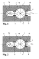
- FIG. 1 shown in a schematic representation of the lamp module according to the invention comprises a lamp holder body 1 made of aluminum, which serves as a cooling body.
- the lamp holder body 1 has a cavity 1a, in which one or more spectral lamps can be used.
- a deuterium lamp with quartz glass lamp bulb 2 and on the same optical axis a halogen lamp with the lamp bulb 3 are used in the cavity 1a of the lamp holder body 1.
- the lamp bulb 2 of the deuterium lamp is made of synthetic quartz glass.
- the lamp envelope 2 is inserted into the lamp holder body 1 leaving a small gap 12 between the holder body 1 and the lamp envelope 2.
- the gap width is about 2 mm.
- the gap volume is filled with air, so that ozone is formed in this small volume by the radiation components emerging from the lamp bulb 2 with wavelengths ⁇ 190 nm. At very small volumes, however, the atmosphere soon becomes saturated with ozone, but this has virtually no effect on the quality of the radiation emerging from the lamp module.
- the gap volume can be evacuated or filled or purged with an oxygen-free gas such as nitrogen or argon.
- the lamp receptacle body 1 further has in the direction of the central optical axis a connecting piece as a beam exit opening 4.
- a beam exit opening 4 is a plano-convex condenser lens 5 fixed with a on the lamp envelope 3 side facing VUV edge filter 6.
- the condenser lens 5 and the VUV edge filter 6 form an integral component, which is arranged on the optical axis of the lamp module at a distance of about 3 mm from the surface of the lamp envelope 2 of the deuterium lamp.
- the VUV edge filter 6 is an interference filter having a multi-layer arrangement.
- the direct arrangement of the filter 6 on the condenser lens 5 minimizes the number of interfaces for the emanating radiation, which increases the proportion of useful radiation over an array with a filter separated from the condenser lens by up to 8%.
- the edge filter 6 consists of a combination of interference and absorption filters.
- a layer system comprising a plurality of interference layers is applied to a base component made of an absorbing material.
- a halogen lamp with a lamp bulb 3 is arranged behind the deuterium lamp.
- the radiation emerging from the lamp bulb 3 of the halogen lamp is passed through the lamp bulb 2 of the deuterium lamp, if appropriate through a lens 8 or a lens system.
- the wavelength ranges of the two spectral lamps complement each other to a broader spectrum, which is cut by the VUV edge filter 6 in the beam exit opening 4 of the lamp module only by the wavelength range less than 190 nm.
- the lamp module according to FIG. 2 consists essentially of the same arrangement as described in Example 1.
- the VUV edge filter 9 is formed as a self-supporting filter plate which is fixed at a distance of 3 mm from the plano-convex condenser lens 5 in the beam exit opening 4.
- the filter plate 9 is enclosed by a screw ring 10, by means of which it is screwed into the jet outlet opening 4.
- the filter plate is clamped or glued into the jet outlet opening 4.
- the filter plate 9 is made of synthetic quartz glass, which is coated with a layer of the filter material. It can be easily mounted and removed, so that a possible replacement by another type of filter or repair reasons is easily possible.
- the fixation is designed so that no exchange of air between the environment and the cavity 1a of the lamp holder body 1 can take place.
- the filter plate 9 is located on a shoulder on a shoulder (not shown) against which it is pressed by means of a spring ring from the inside of the lamp, which in turn is inserted in a groove in the radiation outlet opening 4.
- a sealing fixation of the condenser lens 5 inserted in the direction of the beam exit after the VUV edge filter 9 in the beam exit opening 4 is unnecessary, which possibly facilitates their replacement.
- the edge filter is arranged on the optical axis of the lamp module at a distance of 3 mm from the surface of the lamp bulb 2 of the deuterium lamp. This distance should not be exceeded, since otherwise in the beam exit opening 4 to the VUV edge filter 9 extended gap volume between the lamp envelope 2 of the deuterium lamp and the cavity 1a of the lamp holder body 1 is too large. Under these conditions, the resulting ozone atmosphere may be subject to convection, which in turn could affect the stability of the emerging wavelength spectrum. In addition, the radiation intensity is affected by absorption in the ozone-containing atmosphere.
- the embodiment of the lamp module with self-supporting VUV edge filter 9 is particularly suitable for use as a radiation source of spectrometers, in liquid chromatography (HPLC and UHPLC) in capillary electrophoresis and in thin-layer chromatography.
Landscapes
- Physics & Mathematics (AREA)
- Spectroscopy & Molecular Physics (AREA)
- General Physics & Mathematics (AREA)
- Investigating Or Analysing Materials By Optical Means (AREA)
- Spectrometry And Color Measurement (AREA)
Abstract
Description
- Die Erfindung betrifft ein Lampenmodul insbesondere für Spektralanalysevorrichtungen, umfassend einen Lampenaufnahmekörper, der zur Aufnahme einer Deuteriumlampe mit einem Lampenkolben aus synthetischem Quarzglas einen Hohlraum mit einer Strahlaustrittsöffnung aufweist, die mit einem optischen Durchstrahlungselement verschlossen ist.
- Spektralanalysevorrichtungen erfordern eine hohe optische Stabilität im Sinne eines kontinuierlichen, linienfreien Spektrums im gewünschten Wellenlängenbereich. Deuteriumlampen sind bevorzugte Strahlungsquellen für die UV-Spektroskopie, da sie sehr intensive UV-Strahlung im Bereich 180 nm bis etwa 400 nm emittieren. Um ein erweitertes Spektrum abzudecken wird zu der Deuteriumlampe eine zweite Lampe, - in der Regel eine Halogenlampe -, mit einem Spektrum bis in den sichtbaren Bereich dazu geschaltet. Das Spektrum eines derartig kombinierten Lampenmoduls liegt im Wellenlängenbereich zwischen 180 nm und 1100 nm.
- Ein Problem beim Einsatz von Deuteriumlampen besteht in der Ozonbildung durch die Strahlungsanteile des Deuteriumplasmas unterhalb von 190 nm. Diesem Problem kann begegnet werden, indem für die Lampenkolben der Deuteriumlampe ein spezielles Borosilikatglas, ein so genanntes "UV-Glas" ausgewählt wird, das Strahlung mit einer Wellenlänge kleiner 190 nm absorbiert. Das UV-Glas weist aber keinen steilen Absorptionsverlauf auf, sondern dieser flacht zum langwelligeren Bereich hin ab. Dadurch wird auch noch ein Teil der Arbeitsstrahlung zwischen 190 nm und 280 nm im Lampenkolben absorbiert und steht daher für die spektralanalytischen Zwecke nicht zur Verfügung.
- Bei einer anderen Variante von Deuteriumlampen wird ein Lampenkolben aus synthetischem Quarzglas eingesetzt, der ganz oder teilweise mit einer Schicht bedeckt ist, die als Interferenz- oder Absorptionsfilter für Wellenlängen unterhalb von 190 nm wirkt. Dieser Lampentyp wird als "ozonfrei" definiert, das keine Strahlung einer Ozon generierenden Wellenlänge aus dem Lampenkolben austritt. Jedoch ist die direkte Aufbringung der ozonunterdrückenden Filterschicht auf dem Lampenkolben aufwändig und bietet hinsichtlich der weiteren Gestaltung des Lampenmoduls wenig Spielraum.
- Es sind darüber hinaus auch Deuteriumlampen ohne Ozonfilter auf dem Markt, bei denen bei Arbeiten im kurzwelligen Spektralbereich das entstehende Ozon nach außen zwangsentlüftet wird oder ein so genannter Ozonabsorber das Ozon vor dem Austritt in die Umgebung hindert.
- Aus der
DE 39 02 144 A1 ist eine Deuteriumlampe mit einem Quarzglaskolben bekannt. Der Teilbereich des Lampenkolbens, durch den die erzeugte Strahlung hindurch tritt, ist auf seiner Außenseite mit einem ozonunterdrückenden Filter bedeckt. Es handelt sich um einen Interferenzfilter mit Schichtaufbau, wobei die einzelnen Schichten durch Aufdampfen in Hochvakuumanlagen aufgebracht werden. Diese Auftragsverfahren in Dünnschichttechnik sind kostenintensiv und sind insbesondere für die Herstellung homogener Schichtstrukturen auf gekrümmten Oberflächen nicht uneingeschränkt geeignet. Zudem ist die thermische Belastung dieser Filterschichten direkt auf der Oberfläche des Lampenkolbens im Einsatz sehr hoch, so dass es bereits bei der Herstellung und insbesondere bei längerem Gebrauch dieser Lampen zu einer Schädigung des Filters kommen kann. - Weiterhin ist aus
EP 1 186 828 A1 eine Deuteriumlampe ohne Ozonfilter bekannt. Der Lampenkolben ist in einem Lampenaufnahmekörper aus Aluminium untergebracht, das von rückwärtiger Seite durch einen Kühlungsventilator mit einem Luftstrom zwangsgekühlt wird. Der Lampenaufnahmekörper um den Lampenkolben herum ist bis auf eine kleine, mit einer Kondensorlinse ausgestatteten Öffnung für den Strahlaustritt vollständig geschlossen. An dem Strahlaustrittsfenster des Lampengehäuses befindet sich ein Anschlussstück, das die Strahlung nach außen führt. Der Luftstrom des Ventilators kühlt beziehungsweise temperiert im Wesentlichen den Lampenaufnahmekörper, erreicht aber die kurzwellige Strahlung in der röhrenförmigen Stahlaustrittsöffnung nicht, so dass dort und auch direkt am Lampenkolben kein Ozon entstehen kann. Da aber das aus der Strahlaustrittsöffnung nach außen austretende Spektrum dieser Lampe auch Wellenlängen kleiner 180 nm umfasst, wird die Ozonbildung außerhalb des Lampenmoduls nicht verhindert. - Ein ähnlicher Lampenaufbau ist auch aus der
EP 1 201 984 A1 bekannt. Hier ist jedoch zusätzlich zur Deuteriumlampe noch eine Halogenlampe vorgesehen, um ein erweitertes Wellenlängenspektrum für die Spektralanalyse zur Verfügung zu haben. Derartige Systeme werden auch als UV-VIS-Module bezeichnet, da das Spektrum bis in den sichtbaren Bereich (VIS = visible) reicht. - Deuteriumlampe und Halogenlampe sind hintereinander auf einer gemeinsamen optischen Achse angeordnet. Der Lampenaufnahmekörper des Lampenkolbens der Deuteriumlampe weist in der optischen Achse eine Strahleintrittsöffnung für die Strahlung der hinter der Deuteriumlampe angeordneten Halogenlampe und eine gemeinsame Strahlaustrittsöffnung auf. Beide Lampenkolben können auch im gleichen Lampenaufnahmekörper untergebracht sein. Die Kühlung mittels Ventilator ist auch hier an der Rückseite des Lampengehäuses angeordnet und wirkt auf die aus der Strahlaustrittsöffnung austretende Strahlung nicht. Da kein Ozonfilter vorgesehen ist, wird - wie auch bei der Lampe gemäß
EP 1 186 828 A1 - nur die Ozonbildung innerhalb der Lampe unterdrückt, nicht aber außerhalb der Lampe. - Der Erfindung liegt die Aufgabe zugrunde ein Lampenmodul mit einer Deuteriumlampe mit Ozonfilter bereitzustellen, das eine lange Lebensdauer zeigt, kostengünstig herstellbar ist und eine hohe Intensität im Wellenlängenbereich zwischen 190 nm und 250 nm gewährleistet.
- Diese Aufgabe wird ausgehend von einer Deuteriumlampe der eingangs genannten Gattung erfindungsgemäß dadurch gelöst, dass in der Strahlaustrittsöffnung und auf der der Deuteriumlampe zugewandten Seite des optischen Durchstrahlungselements ein VUV-Kantenfilter vorgesehen ist.
- Bei der erfindungsgemäßen Deuteriumlampe wird ein Lampenkolben aus synthetischem Quarzglas verwendet, das eine exzellente UV-Durchlässigkeit auch im kurzwelligen Bereich bis etwa 150 nm gewährleistet. Der VUV-Kantenfilter absorbiert die kurzwellige UV-Strahlung mit Wellenlängen kleiner 190 nm, die ansonsten zur Ozonbildung außerhalb des Lampenmoduls führen könnte. Auf eine entsprechende Beschichtung des Quarzglas-Lampenkolbens mit einem Ozonfilter kann daher verzichtet werden. Dadurch bestehen vielfältige Möglichkeiten, den Lampenkolben im Gehäuse oder Lampenaufnahmekörper des Lampenmoduls anzuordnen. Der Quarzglas-Lampenkolben ist somit ein Standardbauteil, das eine kostengünstige Komponente für die Herstellung des Lampenmoduls darstellt. Die Abkürzug VUV steht für Vakuum-Ultraviolett und bezeichnet den Spektralbereich von etwa 100 nm bis etwa 190 nm.
- Da der Lampenkolben von dem Lampenaufnahmekörper umschlossen ist und eine Abdichtung gegenüber der Außenluft besteht, wird nur ein kleines Luftvolumen zwischen Quarzglaskolben und Gehäuseinnenraum eingeschlossen. In diesem eng begrenzten Raum ist Ozonbildung durch die aus dem Quarzglaskolben austretende kurzwellige Strahlung möglich und führt dort sehr schnell zu einer gesättigten Atmosphäre, die kaum Konvektion ausgesetzt ist und daher keine Wirkung auf die Stabilität der aus dem Lampenmodul austretenden Strahlung hat.
- Von entscheidender Bedeutung ist, dass durch den in der Strahlaustrittsöffnung angeordneten VUV-Kantenfilter die Ozonbildung durch scharfes Ausfiltern des Wellenlängenbereichs kleiner 190 nm in der Außenumgebung des Lampenmoduls verhindert. Der Filter zeigt daher eine hohe Transmission im Wellenlängenbereich oberhalb von 190 nm, so dass das für spektralanalytische Zwecke nutzbare Spektrum bei dem erfindungsgemäßen Lampenmodul für die meisten Anwendungen dennoch groß genug ist.
- Infolge der Anordnung des Filters in einem Abstand von der Oberfläche des Quarzglaskolbens ist dieser einer geringen thermischen Belastung ausgesetzt, was seine Lebensdauer und damit auch die des gesamten Lampenmoduls deutlich verlängert.
- Bei dem die Strahlaustrittsöffnung verschließenden optischen Durchstrahlungselement handelt es sich beispielsweise um eine Kondensorlinse oder um eine einfache Scheibe, die lediglich als optisches Fenster dient.
- In einer bevorzugten Ausführungsform der Erfindung ist der Lampenkolben in den Hohlraum des Lampenaufnahmekörpers unter Belassung eines Spalts eingefügt, dessen Spaltweite im Bereich zwischen 0,5 mm und 5 mm liegt.
- Außerdem hat es sich als vorteilhaft erwiesen, wenn das optische Durchstrahlungselement in der Strahlaustrittsöffnung in einem Abstand vom Lampenkolben von maximal 20 mm angeordnet ist.
- Durch diese geometrische Auslegung des Raumes um den Lampenkolben herum und zur Strahlauskopplung hin werden die Einflüsse der in diesem Volumen auftretenden Ozonbildung minimiert. Es wird bei dieser Anordnung schnell eine Sättigung der Ozonatmosphäre erreicht, so dass sich keine zeitlich veränderlichen Auswirkungen auf die austretende Strahlung ergeben. Etwaige Intensitätsverluste durch Ozonabsorption im Bereich zwischen 200 nm und 300 nm werden durch eine möglichst kurze optische Weglänge innerhalb der gesättigten Ozonatmosphäre minimiert. Darüber ergibt sich eine optimale Kühlwirkung wenn der kühlbare Lampenaufnahmekörper in geringem Abstand zur Lampenkolbenoberfläche verläuft.
- Eine weitergehende Optimierung im Hinblick auf eine vollständige Unterdrückung der Ozonbildung innerhalb des Lampenaufnahmekörpers kann erreicht werden, wenn der Spalt unter Vakuum gehalten wird oder mit einem sauerstofffreien Gas gefüllt ist.
- Als sauerstofffreie Gase sind Stickstoff oder auch Edelgase geeignet.
- Vorzugsweise ist der Lampenaufnahmekörper als metallischer Kühlköper ausgebildet.
- Je nach Betriebsweise des Lampenmoduls wird der Lampenkolben schnell sehr heiß und muss gekühlt werden. Ist der Lampenaufnahmekörper aus Metall ausgeführt - beispielsweise als Aluminiumbauteil - wirkt das gut Wärme leitende Metall als Kühlkörper, so dass auf eine zusätzliche Ventilation oder andere Kühlmaßnahmen verzichtet werden kann, was einen wirtschaftlichen Betrieb des Lampenmoduls erleichtert.
- In einer bevorzugten Ausführungsform ist der Kantenfilter direkt auf der Oberfläche des optischen Durchstrahlungselements in der Strahlaustrittsöffnung angeordnet.
- Diese Ausführungsform hat den Vorteil, dass im optischen System die Anzahl der Grenzflächen, durch die die Strahlung hindurchtreten muss beziehungsweise an denen Strahlung absorbiert wird, gegenüber einem separaten Kantenfilter verringert wird und im Vergleich dazu der Anteil an nutzbarer Strahlung um bis zu etwa 8 % höher liegt. Außerdem können solche Kantenfilter mittels kostengünstiger Verfahren auf Linsen oder ebenen Fenstern aufgetragen werden.
- Eine Alternative für die Anordnung des Kantenfilters besteht darin, dass der Filter in einem Abstand von der Oberfläche des optischen Durchstrahlungselements in der Strahlaustrittsöffnung angeordnet ist.
- Diese Anordnung hat den Vorteil, dass der Kantenfilter als eigenständiges Bauteil eingesetzt werden und auch bei Bedarf ausgetauscht werden kann. Filterplättchen dieser Art sind robust und ihre Montage in der Strahlaustrittsöffnung ist einfach. Sie liegen beispielsweise als Platte aus absorbierendem Filterglas vor oder in Form einer Platte aus synthetischem Quarzglas vor, das mit dem Filtermaterial beschichtet ist. Da das separate Filterbauteil - im Gegensatz zum Lampenkolben - kaum mechanischen Belastungen ausgesetzt ist, kann es wesentlich dünner sein, als die Wandung des Lampenkolbens. Bevorzugte Dicken des Filterbauteils liegen im Bereich von 0,1 bis 1 mm, besonders bevorzugt maximal 0,3 mm. wegen der geringeren Dicke ist die Transmission für die gewünschte optische Strahlung beim Filterbauteil größer als beim Lampenkolben.
- Vorteilhafterweise ist der VUV-Kantenfilter ein Absorptionsfilter oder ein Interferenzfilter oder eine Kombination dieser beiden Filtertypen.
- Absorptionsfilter bestehen aus einem absorbierenden Werkstoff, wie beispielsweise einem UV-absorbierenden Glas. Sie sind kostengünstig, zeigen aber häufig eine wenig steile Absorptionskante, die materialabhängig und nicht veränderbar ist. Diese Nachteile vermeiden Interferenzfilter, wie sie beispielsweise in der
DE 39 021 44 A1 beschrieben sind. Diese bestehen aus einem beschichteten Grundwerkstoff, wobei die Lage der Absorptionskante über die Dicke der Beschichtung beeinflusst werden kann. - Es hat sich bewährt, wenn der Kantenfilter ein Mehrfachschichtmaterial umfasst.
- Bei einem Kantenfilter aus einem Mehrfachschichtmaterial kann die Lage und Steilheit der Absorptionskante an die konkreten Anforderungen besser angepasst und optimiert werden. Zudem wird durch Mehrfachschichten die so genannte "Welligkeit" der Filterwirkung im Bereich der Transmissionswellenlänge verringert, die auf Interferenzeffekte zurückzuführen ist.
- Die Absorptionskante des Kantenfilters liegt bevorzugt im Bereich von 180 nm bis 200 nm.
- Um den Austritt von Ozon aus dem Lampengehäuse zu vermindern oder zu verhindern, ist die Strahlaustrittsöffnung vorzugsweise außen abgedichtet ist.
- Bei geringen Anforderungen an die Dichtheit kann hierfür ein feines Gewinde zwischen der Kondensorlinse und dem Lampengehäuse genügen.
- Im Hinblick auf eine Erweiterung des Wellenlängenbereichs wird eine Ausführungsform des Lampenmoduls besonders bevorzugt, bei dem im Hohlraum des Lampenaufnahmekörpers eine zweite Spektral-Lampe angeordnet ist, deren Strahl durch den Lampenkolben der Deuteriumlampe hindurch zur Strahlaustrittsöffnung gelenkt wird.
- Für die Spektralphotometrie ist es vorteilhaft, wenn der Wellenlängenbereich des nutzbaren Spektrums möglichst breit ist. Der Einsatz einer zweiten Spektral-Lampe mit anderem Emissionsspektrum als die Deuteriumlampe kommt dieser Anforderung entgegen. Überdies kann von Fall zu Fall auch nur eine der beiden Spektral-Lampen zum Einsatz kommen, so dass ein derartiges Lampenmodul flexibel einsetzbar ist.
- Für die Spektralphotometeranwendung hat es sich bewährt, wenn die zweite Spektral-Lampe eine Halogenlampe oder eine LED ist.
- Der typischerweise bei Halogenlampen genutzte Wellenlängenbereich der Strahlung liegt zwischen 350 und 1100 nm. Somit deckt die Kombination mit einer Deuteriumlampe ein breites Spektrum von 190 nm bis 1100 nm ab.
- Nachfolgend wird die Erfindung anhand von Ausführungsbeispielen und einer Zeichnung näher erläutert. Es zeigt dabei in schematischer Darstellung im Einzelnen:
- Figur 1
- eine Ausführungsform des erfindungsgemäßen Lampenmoduls in einer Seitenansicht im Schnitt mit einem Filter direkt auf der Oberfläche der Kondensorlinse, und
- Figur 2
- eine weitere Ausführungsform des erfindungsgemäßen Lampenmoduls in einer Seitenansicht im Schnitt mit einem von der Kondensorlinse beabstandeten Filter.
- Die in
Figur 1 in schematischer Darstellung gezeigte Ausführung des erfindungsgemäßen Lampenmoduls weist einen aus Aluminium bestehenden Lampenaufnahmekörper 1 auf, der als Kühlköper dient. Der Lampenaufnahmekörper 1 hat einen Hohlraum 1a, in den ein oder mehrere Spektrallampen einsetzbar sind. Im konkreten Fall sind im Hohlraum 1a des Lampenaufnahmekörpers 1 eine Deuteriumlampe mit Quarzglas-Lampenkolben 2 und auf derselben optischen Achse eine Halogenlampe mit dem Lampenkolben 3 eingesetzt. - Der Lampenkolben 2 der Deuteriumlampe besteht aus synthetischem Quarzglas. Um die Kühlwirkung des Lampenaufnahmekörpers 1 auf die in seinem Hohlraum 1 a eingesetzten Lampenkolben 2 optimal ausnutzen zu können, ist der Lampenkolben 2 unter Belassung eines geringen Spalts 12 zwischen Aufnahmekörper 1 und Lampenkolben 2 in den Lampenaufnahmekörper 1 eingesetzt. Die Spaltweite beträgt etwa 2 mm.
- Das Spaltvolumen ist mit Luft gefüllt, so dass in diesem kleinen Volumen durch die aus dem Lampenkolben 2 austretenden Strahlungsanteile mit Wellenlängen <190 nm Ozon gebildet wird. Bei sehr kleinen Volumina ist die Atmosphäre jedoch sehr bald mit Ozon gesättigt, was aber praktisch keinen Einfluss auf die Qualität der aus dem Lampenmodul austretenden Strahlung hat.
- Wenn auch in diesem Spaltvolumen die Ozonbildung verhindert werden soll, kann das Spaltvolumen evakuiert oder mit einem sauerstofffreien Gas, wie etwa Stickstoff oder Argon gefüllt oder gespült werden.
- Der Lampenaufnahmekörper 1 hat weiterhin in Richtung der zentralen optischen Achse ein Anschlussstück als Strahlaustrittsöffnung 4. In dieser Strahlaustrittsöffnung 4 ist eine plankonvexe Kondensorlinse 5 mit einem auf der dem Lampenkolben 3 zugewandten Seite aufgebrachten VUV-Kantenfilter 6 fixiert. Die Kondensorlinse 5 und der VUV-Kantenfilter 6 bilden ein integrales Bauteil, das auf der optischen Achse des Lampenmoduls im Abstand von etwa 3 mm von der Oberfläche des Lampenkolbens 2 der Deuteriumlampe entfernt angeordnet ist.
- Die Fixierung von Kondensorlinse 5 und Filter 6 erfolgt dadurch, dass die Bauteile in einer gedichteten Ringfassung 10 umlaufend in die Strahlaustrittsöffnung 4 eingeklebt werden. Es ist damit gewährleistet, dass kein Luftaustausch zwischen der Umgebung und dem Hohlraum 1a des Lampenaufnahmekörpers 1 stattfinden kann.
- Der VUV-Kantenfilter 6 ist ein Interferenzfilter mit einer Mehrfachschichtanordnung. Durch die direkte Anordnung des Filters 6 auf der Kondensorlinse 5 wird die Anzahl der Grenzflächen für die austretende Strahlung minimiert, was den Anteil der nutzbaren Strahlung gegenüber einer Anordnung mit einem von der Kondensorlinse getrennt angeordneten Filter um bis zu 8 % erhöht.
- In einer alternativen Ausführungsform besteht der Kantenfilter 6 aus einer Kombination aus Interferenz- und Absorptionsfilter. Dabei wird auf ein Grundbauteil aus einem absorbierenden Werkstoff ein Schichtsystem aus mehreren Interferenzschichten aufgetragen.
- An der der Strahlaustrittsöffnung 4 auf der optischen Achse gegenüberliegenden Seite ist, wie anfangs erwähnt, hinter der Deuteriumlampe eine Halogenlampe mit einem Lampenkolben 3 angeordnet. Die aus dem Lampenkolben 3 der Halogenlampe austretende Strahlung wird, gegebenenfalls über eine Linse 8 oder ein Linsensystem gebündelt, durch den Lampenkolben 2 der Deuteriumlampe hindurchgeführt. Somit ergänzen sich die Wellenlängenbereiche der beiden Spektral-Lampen zu einem breiteren Spektrum, das durch den VUV-Kantenfilter 6 in der Strahlaustrittsöffnung 4 des Lampenmoduls nur durch den Wellenlängenbereich kleiner 190 nm beschnitten wird.
- Das Lampenmodul gemäß
Figur 2 besteht im Wesentlichen aus der gleichen Anordnung wie im Beispiel 1 beschrieben. Jedoch ist hier der VUV-Kantenfilter 9 als ein selbstragendes Filterplättchen ausgebildet, das in einem Abstand von 3 mm von der plankonvexen Kondensorlinse 5 in der Strahlaustrittsöffnung 4 fixiert ist. Das Filterplättchen 9 ist mit einem Schraubring 10 eingefasst, mittels dem es in der Strahlaustrittsöffnung 4 eingeschraubt ist. Bei alternativen Ausführungsformen ist das Filterplättchen in die Strahlaustrittsöffnung 4 eingeklemmt oder eingeklebt. - In diesem Fall besteht das Filterplättchen 9 aus synthetischem Quarzglas, das mit einer Schicht aus dem Filtermaterial beschichtet ist. Es kann leicht montiert und entnommen werden, so dass auch ein eventueller Ersatz durch einen anderen Filtertyp oder aus Reparaturgründen einfach möglich ist. Die Fixierung ist so gestaltet, dass kein Luftaustausch zwischen der Umgebung und dem Hohlraum 1a des Lampenaufnahmekörpers 1 stattfinden kann. Zu diesem Zweck liegt das Filterplättchen 9 über einen Dichtring an einem Absatz an (nicht dargestellt), gegen den es mittels eines Federringes von der Lampeninnenseite aus gepresst wird, der wiederum in einer Nut in der Strahlenaustrittsöffnung 4 eingelegt ist.
- Bei dieser Ausführungsform erübrigt sich eine abdichtende Fixierung der in Richtung Strahlaustritt nach dem VUV-Kantenfilter 9 in der Strahlaustrittsöffnung 4 eingesetzten Kondensorlinse 5, was deren Austausch gegebenenfalls erleichtert.
- Der Kantenfilter ist auf der optischen Achse des Lampenmoduls im Abstand von 3 mm von der Oberfläche des Lampenkolbens 2 der Deuteriumlampe angeordnet. Dieses Abstandsmaß sollte nicht überschritten werden, da sonst das in die Strahlaustrittsöffnung 4 bis zum VUV-Kantenfilter 9 erweiterte Spaltvolumen zwischen dem Lampenkolben 2 der Deuteriumlampe und dem Hohlraum 1a des Lampenaufnahmekörpers 1 zu groß wird. Unter diesen Bedingungen kann die dort entstehende Ozonatmosphäre unter Konvektionseinfluss geraten, was wiederum die Stabilität des austretenden Wellenlängenspektrums beeinträchtigen könnte. Zudem wird die Strahlungsintensität durch Absorption in der ozonhaltigen Atmosphäre beeinträchtigt.
- Die Ausführungsform des Lampenmoduls mit selbsttragendem VUV-Kantenfilter 9 ist besonders geeignet für einen Einsatz als Strahlenquelle von Spektrometern, in der Flüssigkeitschromatographie (HPLC und UHPLC) in der Kapillarelektrophorese und in der Dünnschichtchromatographie.
Claims (14)
- Lampenmodul insbesondere für Spektralanalysevorrichtungen, umfassend einen Lampenaufnahmekörper (1), der zur Aufnahme einer Deuteriumlampe (2) mit einem Lampenkolben aus synthetischem Quarzglas einen Hohlraum (1a) mit einer Strahlaustrittsöffnung (4) aufweist, die mit einem optischen Durchstrahlungselement (5) verschlossen ist, dadurch gekennzeichnet, dass in der Strahlaustrittsöffnung (4) und auf der der Deuteriumlampe (2) zugewandten Seite des optischen Durchstrahlungselements (5) ein VUV-Kantenfilter (6; 9)) vorgesehen ist.
- Lampenmodul nach Anspruch 1, dadurch gekennzeichnet, dass der Lampenkolben in den Hohlraum (12) des Lampenaufnahmekörpers unter Belassung eines Spalts (2a) eingefügt ist, dessen Spaltweite im Bereich zwischen 0,5 mm und 5 mm liegt.
- Lampenmodul nach Anspruch 1 oder 2, dadurch gekennzeichnet, dass das optische Durchstrahlungselement (5) in der Strahlaustrittsöffnung (4) in einem Abstand vom Lampenkolben von maximal 20 mm angeordnet ist.
- Lampenmodul nach Anspruch 2, dadurch gekennzeichnet, dass der Spalt (2a) unter Vakuum gehalten wird oder mit einem sauerstofffreien Gas gefüllt ist.
- Lampenmodul nach einem der vorhergehenden Ansprüche, dadurch gekennzeichnet, dass der Lampenaufnahmekörper (1) als metallischer Kühlkörper ausgebildet ist.
- Lampenmodul nach einem der vorhergehenden Ansprüche, dadurch gekennzeichnet, dass der Kantenfilter (6) direkt auf der Oberfläche des optischen Durchstrahlungselements (5) in der Strahlaustrittsöffnung (4) angeordnet ist.
- Lampenmodul nach einem der Ansprüche 1 bis 5, dadurch gekennzeichnet, dass der Kantenfilter (9) in einem Abstand von der Oberfläche des optischen Durchstrahlungselements (5) in der Strahlaustrittsöffnung (4) angeordnet ist.
- Lampenmodul nach Anspruch 7, dadurch gekennzeichnet, dass der Kantenfilter (9) eine Dicke im Bereich von 0,1 bis 1 mm, vorzugsweise eine Dicke von maximal 0,3 mm aufweist.
- Lampenmodul nach einem der vorhergehenden Ansprüche, dadurch gekennzeichnet, dass der Kantenfilter (6; 9) ein Absorptionsfilter oder ein Interferenzfilter oder eine Kombination dieser beiden Filtertypen ist.
- Lampenmodul nach einem der vorhergehenden Ansprüche, dadurch gekennzeichnet, dass der Kantenfilter (6; 9) ein Mehrfachschichtmaterial umfasst.
- Lampenmodul nach einem der vorhergehenden Ansprüche, dadurch gekennzeichnet, dass die Strahlaustrittsöffnung (4) nach außen abgedichtet ist.
- Lampenmodul nach einem der vorhergehenden Ansprüche, dadurch gekennzeichnet, dass der Kantenfilter (6; 9) eine Absorptionskante im Bereich von 180-200 nm hat.
- Lampenmodul nach einem der vorhergehenden Ansprüche, dadurch gekennzeichnet, dass in dem Hohlraum (12) des Lampenaufnahmekörpers (1) eine zweite Spektral-Lampe (3) angeordnet ist, deren Strahl durch den Lampenkolben der Deuteriumlampe (2) hindurch zur Strahlaustrittsöffnung (4) gelenkt wird.
- Lampenmodul nach Anspruch 13, dadurch gekennzeichnet, dass die zweite Spektral-Lampe (3) eine Halogenlampe oder eine LED ist.
Applications Claiming Priority (1)
| Application Number | Priority Date | Filing Date | Title |
|---|---|---|---|
| DE102011018986A DE102011018986A1 (de) | 2011-04-28 | 2011-04-28 | Lampenmodul, insbesondere für Spektralanalysevorrichtungen |
Publications (2)
| Publication Number | Publication Date |
|---|---|
| EP2518460A1 true EP2518460A1 (de) | 2012-10-31 |
| EP2518460B1 EP2518460B1 (de) | 2020-04-29 |
Family
ID=46000610
Family Applications (1)
| Application Number | Title | Priority Date | Filing Date |
|---|---|---|---|
| EP12002086.2A Not-in-force EP2518460B1 (de) | 2011-04-28 | 2012-03-23 | Lampenmodul mit einer Deuterium-Lampe |
Country Status (9)
| Country | Link |
|---|---|
| US (1) | US8415866B2 (de) |
| EP (1) | EP2518460B1 (de) |
| JP (1) | JP5602785B2 (de) |
| KR (1) | KR101401192B1 (de) |
| CN (1) | CN102759401B (de) |
| AU (1) | AU2012201707B2 (de) |
| DE (1) | DE102011018986A1 (de) |
| MY (1) | MY164670A (de) |
| SG (1) | SG185190A1 (de) |
Families Citing this family (8)
| Publication number | Priority date | Publication date | Assignee | Title |
|---|---|---|---|---|
| US10307167B2 (en) | 2012-12-14 | 2019-06-04 | Corquest Medical, Inc. | Assembly and method for left atrial appendage occlusion |
| US10314594B2 (en) | 2012-12-14 | 2019-06-11 | Corquest Medical, Inc. | Assembly and method for left atrial appendage occlusion |
| US10813630B2 (en) | 2011-08-09 | 2020-10-27 | Corquest Medical, Inc. | Closure system for atrial wall |
| US20140142689A1 (en) | 2012-11-21 | 2014-05-22 | Didier De Canniere | Device and method of treating heart valve malfunction |
| WO2015055387A1 (en) | 2013-10-17 | 2015-04-23 | Asml Netherlands B.V. | Photon source, metrology apparatus, lithographic system and device manufacturing method |
| US9566443B2 (en) | 2013-11-26 | 2017-02-14 | Corquest Medical, Inc. | System for treating heart valve malfunction including mitral regurgitation |
| DE102014105028A1 (de) * | 2014-04-09 | 2015-04-09 | Heraeus Noblelight Gmbh | Gasentladungslampe und deren Verwendung |
| US10842626B2 (en) | 2014-12-09 | 2020-11-24 | Didier De Canniere | Intracardiac device to correct mitral regurgitation |
Citations (7)
| Publication number | Priority date | Publication date | Assignee | Title |
|---|---|---|---|---|
| US4049987A (en) * | 1976-06-04 | 1977-09-20 | The Perkin-Elmer Corporation | Ozone absorbance controller |
| US4812657A (en) * | 1985-10-31 | 1989-03-14 | Kabushiki Kaisha Toshiba | Multiunit tube and a spectrophotometer |
| US4910431A (en) * | 1987-04-24 | 1990-03-20 | W. C. Heraeus Gmbh | Hydrogen discharge ultraviolet light source or lamp, and method of its manufacture |
| DE3902144A1 (de) | 1989-01-25 | 1990-08-02 | Heraeus Gmbh W C | Deuterium-lampe fuer spektralanalyse-vorrichtungen |
| EP1186828A1 (de) | 1999-04-28 | 2002-03-13 | Hamamatsu Photonics K.K. | Tragbare lichtquelle |
| EP1201984A1 (de) | 1999-07-16 | 2002-05-02 | Hamamatsu Photonics K.K. | Deuteriumlampen-gehäuse und tragbare lichtquelle |
| CN2861710Y (zh) * | 2005-08-16 | 2007-01-24 | 张华强 | 多功能手提式聚光灯 |
Family Cites Families (6)
| Publication number | Priority date | Publication date | Assignee | Title |
|---|---|---|---|---|
| JPS62199645U (de) * | 1986-06-11 | 1987-12-19 | ||
| JPH0743938Y2 (ja) * | 1991-08-19 | 1995-10-09 | 江東電気株式会社 | 重水素放電管 |
| JP2771785B2 (ja) * | 1995-04-13 | 1998-07-02 | 雅則 奥山 | スペクトル画像分析装置 |
| AU753047B2 (en) * | 1997-11-14 | 2002-10-03 | Ethicon Inc. | Method for measuring the concentration of hydrogen peroxide vapor |
| US7176633B1 (en) * | 2003-12-09 | 2007-02-13 | Vaconics Lighting, Inc. | Arc lamp with an internally mounted filter |
| JP5151073B2 (ja) * | 2006-06-02 | 2013-02-27 | 株式会社島津製作所 | 光度計 |
-
2011
- 2011-04-28 DE DE102011018986A patent/DE102011018986A1/de not_active Ceased
-
2012
- 2012-03-22 AU AU2012201707A patent/AU2012201707B2/en not_active Ceased
- 2012-03-22 SG SG2012020699A patent/SG185190A1/en unknown
- 2012-03-23 EP EP12002086.2A patent/EP2518460B1/de not_active Not-in-force
- 2012-04-05 US US13/440,260 patent/US8415866B2/en not_active Expired - Fee Related
- 2012-04-25 KR KR1020120042964A patent/KR101401192B1/ko not_active Expired - Fee Related
- 2012-04-26 MY MYPI2012001866A patent/MY164670A/en unknown
- 2012-04-27 JP JP2012103616A patent/JP5602785B2/ja not_active Expired - Fee Related
- 2012-04-27 CN CN201210127480.9A patent/CN102759401B/zh not_active Expired - Fee Related
Patent Citations (7)
| Publication number | Priority date | Publication date | Assignee | Title |
|---|---|---|---|---|
| US4049987A (en) * | 1976-06-04 | 1977-09-20 | The Perkin-Elmer Corporation | Ozone absorbance controller |
| US4812657A (en) * | 1985-10-31 | 1989-03-14 | Kabushiki Kaisha Toshiba | Multiunit tube and a spectrophotometer |
| US4910431A (en) * | 1987-04-24 | 1990-03-20 | W. C. Heraeus Gmbh | Hydrogen discharge ultraviolet light source or lamp, and method of its manufacture |
| DE3902144A1 (de) | 1989-01-25 | 1990-08-02 | Heraeus Gmbh W C | Deuterium-lampe fuer spektralanalyse-vorrichtungen |
| EP1186828A1 (de) | 1999-04-28 | 2002-03-13 | Hamamatsu Photonics K.K. | Tragbare lichtquelle |
| EP1201984A1 (de) | 1999-07-16 | 2002-05-02 | Hamamatsu Photonics K.K. | Deuteriumlampen-gehäuse und tragbare lichtquelle |
| CN2861710Y (zh) * | 2005-08-16 | 2007-01-24 | 张华强 | 多功能手提式聚光灯 |
Also Published As
| Publication number | Publication date |
|---|---|
| US8415866B2 (en) | 2013-04-09 |
| KR101401192B1 (ko) | 2014-05-28 |
| US20120274198A1 (en) | 2012-11-01 |
| DE102011018986A1 (de) | 2012-10-31 |
| CN102759401A (zh) | 2012-10-31 |
| JP2012233897A (ja) | 2012-11-29 |
| KR20120122916A (ko) | 2012-11-07 |
| JP5602785B2 (ja) | 2014-10-08 |
| EP2518460B1 (de) | 2020-04-29 |
| AU2012201707B2 (en) | 2014-03-20 |
| MY164670A (en) | 2018-01-30 |
| CN102759401B (zh) | 2014-11-19 |
| AU2012201707A1 (en) | 2012-11-15 |
| SG185190A1 (en) | 2012-11-29 |
Similar Documents
| Publication | Publication Date | Title |
|---|---|---|
| EP2518460B1 (de) | Lampenmodul mit einer Deuterium-Lampe | |
| DE3688228T2 (de) | Infrarotprojektor. | |
| DD274871A5 (de) | Polarisiertes licht ausstrahlende behandlungsleuchte | |
| DE102013017141B4 (de) | Röhrenförmige LED-Lampe mit innenliegender, zylindrischer Sammellinse | |
| EP2149748B1 (de) | Scheinwerfer für Fahrzeuge | |
| AT518666B1 (de) | Kraftfahrzeug-Scheinwerfer | |
| EP2245709B1 (de) | Laserkristalleinrichtung | |
| EP1045195B1 (de) | Leuchte | |
| EP2981984B1 (de) | Leuchte | |
| DE9313409U1 (de) | Entkeimungsgerät | |
| DE202013002133U1 (de) | Kraftfahrzeugbeleuchtungseinrichtung mit einer Heizeinrichtung | |
| EP2057663B1 (de) | Durchschein-wasserstofflampe | |
| DE19603025A1 (de) | Lichtgenerator zur Einspeisung in Lichtleitfasern | |
| WO2004068120A1 (de) | Infrarotquelle und gassensor | |
| DE102014105028A1 (de) | Gasentladungslampe und deren Verwendung | |
| DE202005011364U1 (de) | Reflektorlampe | |
| WO2021043480A1 (de) | Vorrichtung zur bestrahlung einer fläche | |
| EP1158566A1 (de) | Leuchtkörper für eine Lampe, insbesondere Entladungslampen | |
| DE102015225085A1 (de) | Reflektor und Gasentladungslampe mit dem Reflektor für eine verbesserte Farbwiedergabe | |
| DE4334025A1 (de) | Reinraumleuchte | |
| DE19963838A1 (de) | Getter-Spritzabschirmung | |
| DE9002879U1 (de) | Leuchte | |
| DE1539465C3 (de) | Luftgekühlte Spezialleuchte mit Hochleistungslampe | |
| EP2956710B1 (de) | Längliche leuchte | |
| AT16244U1 (de) | Leuchtvorrichtung |
Legal Events
| Date | Code | Title | Description |
|---|---|---|---|
| PUAI | Public reference made under article 153(3) epc to a published international application that has entered the european phase |
Free format text: ORIGINAL CODE: 0009012 |
|
| 17P | Request for examination filed |
Effective date: 20120405 |
|
| AK | Designated contracting states |
Kind code of ref document: A1 Designated state(s): AL AT BE BG CH CY CZ DE DK EE ES FI FR GB GR HR HU IE IS IT LI LT LU LV MC MK MT NL NO PL PT RO RS SE SI SK SM TR |
|
| AX | Request for extension of the european patent |
Extension state: BA ME |
|
| STAA | Information on the status of an ep patent application or granted ep patent |
Free format text: STATUS: EXAMINATION IS IN PROGRESS |
|
| 17Q | First examination report despatched |
Effective date: 20180703 |
|
| GRAP | Despatch of communication of intention to grant a patent |
Free format text: ORIGINAL CODE: EPIDOSNIGR1 |
|
| STAA | Information on the status of an ep patent application or granted ep patent |
Free format text: STATUS: GRANT OF PATENT IS INTENDED |
|
| INTG | Intention to grant announced |
Effective date: 20200205 |
|
| GRAS | Grant fee paid |
Free format text: ORIGINAL CODE: EPIDOSNIGR3 |
|
| GRAA | (expected) grant |
Free format text: ORIGINAL CODE: 0009210 |
|
| STAA | Information on the status of an ep patent application or granted ep patent |
Free format text: STATUS: THE PATENT HAS BEEN GRANTED |
|
| AK | Designated contracting states |
Kind code of ref document: B1 Designated state(s): AL AT BE BG CH CY CZ DE DK EE ES FI FR GB GR HR HU IE IS IT LI LT LU LV MC MK MT NL NO PL PT RO RS SE SI SK SM TR |
|
| REG | Reference to a national code |
Ref country code: GB Ref legal event code: FG4D Free format text: NOT ENGLISH |
|
| REG | Reference to a national code |
Ref country code: CH Ref legal event code: EP |
|
| REG | Reference to a national code |
Ref country code: DE Ref legal event code: R096 Ref document number: 502012016006 Country of ref document: DE |
|
| REG | Reference to a national code |
Ref country code: AT Ref legal event code: REF Ref document number: 1264012 Country of ref document: AT Kind code of ref document: T Effective date: 20200515 |
|
| REG | Reference to a national code |
Ref country code: IE Ref legal event code: FG4D Free format text: LANGUAGE OF EP DOCUMENT: GERMAN |
|
| REG | Reference to a national code |
Ref country code: NL Ref legal event code: MP Effective date: 20200429 |
|
| REG | Reference to a national code |
Ref country code: LT Ref legal event code: MG4D |
|
| PG25 | Lapsed in a contracting state [announced via postgrant information from national office to epo] |
Ref country code: GR Free format text: LAPSE BECAUSE OF FAILURE TO SUBMIT A TRANSLATION OF THE DESCRIPTION OR TO PAY THE FEE WITHIN THE PRESCRIBED TIME-LIMIT Effective date: 20200730 Ref country code: LT Free format text: LAPSE BECAUSE OF FAILURE TO SUBMIT A TRANSLATION OF THE DESCRIPTION OR TO PAY THE FEE WITHIN THE PRESCRIBED TIME-LIMIT Effective date: 20200429 Ref country code: FI Free format text: LAPSE BECAUSE OF FAILURE TO SUBMIT A TRANSLATION OF THE DESCRIPTION OR TO PAY THE FEE WITHIN THE PRESCRIBED TIME-LIMIT Effective date: 20200429 Ref country code: SE Free format text: LAPSE BECAUSE OF FAILURE TO SUBMIT A TRANSLATION OF THE DESCRIPTION OR TO PAY THE FEE WITHIN THE PRESCRIBED TIME-LIMIT Effective date: 20200429 Ref country code: PT Free format text: LAPSE BECAUSE OF FAILURE TO SUBMIT A TRANSLATION OF THE DESCRIPTION OR TO PAY THE FEE WITHIN THE PRESCRIBED TIME-LIMIT Effective date: 20200831 Ref country code: IS Free format text: LAPSE BECAUSE OF FAILURE TO SUBMIT A TRANSLATION OF THE DESCRIPTION OR TO PAY THE FEE WITHIN THE PRESCRIBED TIME-LIMIT Effective date: 20200829 Ref country code: NO Free format text: LAPSE BECAUSE OF FAILURE TO SUBMIT A TRANSLATION OF THE DESCRIPTION OR TO PAY THE FEE WITHIN THE PRESCRIBED TIME-LIMIT Effective date: 20200729 |
|
| PG25 | Lapsed in a contracting state [announced via postgrant information from national office to epo] |
Ref country code: BG Free format text: LAPSE BECAUSE OF FAILURE TO SUBMIT A TRANSLATION OF THE DESCRIPTION OR TO PAY THE FEE WITHIN THE PRESCRIBED TIME-LIMIT Effective date: 20200729 Ref country code: RS Free format text: LAPSE BECAUSE OF FAILURE TO SUBMIT A TRANSLATION OF THE DESCRIPTION OR TO PAY THE FEE WITHIN THE PRESCRIBED TIME-LIMIT Effective date: 20200429 Ref country code: HR Free format text: LAPSE BECAUSE OF FAILURE TO SUBMIT A TRANSLATION OF THE DESCRIPTION OR TO PAY THE FEE WITHIN THE PRESCRIBED TIME-LIMIT Effective date: 20200429 Ref country code: LV Free format text: LAPSE BECAUSE OF FAILURE TO SUBMIT A TRANSLATION OF THE DESCRIPTION OR TO PAY THE FEE WITHIN THE PRESCRIBED TIME-LIMIT Effective date: 20200429 |
|
| PG25 | Lapsed in a contracting state [announced via postgrant information from national office to epo] |
Ref country code: AL Free format text: LAPSE BECAUSE OF FAILURE TO SUBMIT A TRANSLATION OF THE DESCRIPTION OR TO PAY THE FEE WITHIN THE PRESCRIBED TIME-LIMIT Effective date: 20200429 Ref country code: NL Free format text: LAPSE BECAUSE OF FAILURE TO SUBMIT A TRANSLATION OF THE DESCRIPTION OR TO PAY THE FEE WITHIN THE PRESCRIBED TIME-LIMIT Effective date: 20200429 |
|
| PG25 | Lapsed in a contracting state [announced via postgrant information from national office to epo] |
Ref country code: EE Free format text: LAPSE BECAUSE OF FAILURE TO SUBMIT A TRANSLATION OF THE DESCRIPTION OR TO PAY THE FEE WITHIN THE PRESCRIBED TIME-LIMIT Effective date: 20200429 Ref country code: DK Free format text: LAPSE BECAUSE OF FAILURE TO SUBMIT A TRANSLATION OF THE DESCRIPTION OR TO PAY THE FEE WITHIN THE PRESCRIBED TIME-LIMIT Effective date: 20200429 Ref country code: SM Free format text: LAPSE BECAUSE OF FAILURE TO SUBMIT A TRANSLATION OF THE DESCRIPTION OR TO PAY THE FEE WITHIN THE PRESCRIBED TIME-LIMIT Effective date: 20200429 Ref country code: ES Free format text: LAPSE BECAUSE OF FAILURE TO SUBMIT A TRANSLATION OF THE DESCRIPTION OR TO PAY THE FEE WITHIN THE PRESCRIBED TIME-LIMIT Effective date: 20200429 Ref country code: CZ Free format text: LAPSE BECAUSE OF FAILURE TO SUBMIT A TRANSLATION OF THE DESCRIPTION OR TO PAY THE FEE WITHIN THE PRESCRIBED TIME-LIMIT Effective date: 20200429 Ref country code: RO Free format text: LAPSE BECAUSE OF FAILURE TO SUBMIT A TRANSLATION OF THE DESCRIPTION OR TO PAY THE FEE WITHIN THE PRESCRIBED TIME-LIMIT Effective date: 20200429 Ref country code: IT Free format text: LAPSE BECAUSE OF FAILURE TO SUBMIT A TRANSLATION OF THE DESCRIPTION OR TO PAY THE FEE WITHIN THE PRESCRIBED TIME-LIMIT Effective date: 20200429 |
|
| REG | Reference to a national code |
Ref country code: DE Ref legal event code: R097 Ref document number: 502012016006 Country of ref document: DE |
|
| PG25 | Lapsed in a contracting state [announced via postgrant information from national office to epo] |
Ref country code: PL Free format text: LAPSE BECAUSE OF FAILURE TO SUBMIT A TRANSLATION OF THE DESCRIPTION OR TO PAY THE FEE WITHIN THE PRESCRIBED TIME-LIMIT Effective date: 20200429 Ref country code: SK Free format text: LAPSE BECAUSE OF FAILURE TO SUBMIT A TRANSLATION OF THE DESCRIPTION OR TO PAY THE FEE WITHIN THE PRESCRIBED TIME-LIMIT Effective date: 20200429 |
|
| PLBE | No opposition filed within time limit |
Free format text: ORIGINAL CODE: 0009261 |
|
| STAA | Information on the status of an ep patent application or granted ep patent |
Free format text: STATUS: NO OPPOSITION FILED WITHIN TIME LIMIT |
|
| 26N | No opposition filed |
Effective date: 20210201 |
|
| PG25 | Lapsed in a contracting state [announced via postgrant information from national office to epo] |
Ref country code: SI Free format text: LAPSE BECAUSE OF FAILURE TO SUBMIT A TRANSLATION OF THE DESCRIPTION OR TO PAY THE FEE WITHIN THE PRESCRIBED TIME-LIMIT Effective date: 20200429 |
|
| PG25 | Lapsed in a contracting state [announced via postgrant information from national office to epo] |
Ref country code: MC Free format text: LAPSE BECAUSE OF FAILURE TO SUBMIT A TRANSLATION OF THE DESCRIPTION OR TO PAY THE FEE WITHIN THE PRESCRIBED TIME-LIMIT Effective date: 20200429 |
|
| REG | Reference to a national code |
Ref country code: CH Ref legal event code: PL |
|
| REG | Reference to a national code |
Ref country code: BE Ref legal event code: MM Effective date: 20210331 |
|
| PG25 | Lapsed in a contracting state [announced via postgrant information from national office to epo] |
Ref country code: CH Free format text: LAPSE BECAUSE OF NON-PAYMENT OF DUE FEES Effective date: 20210331 Ref country code: LI Free format text: LAPSE BECAUSE OF NON-PAYMENT OF DUE FEES Effective date: 20210331 Ref country code: LU Free format text: LAPSE BECAUSE OF NON-PAYMENT OF DUE FEES Effective date: 20210323 Ref country code: IE Free format text: LAPSE BECAUSE OF NON-PAYMENT OF DUE FEES Effective date: 20210323 |
|
| PGFP | Annual fee paid to national office [announced via postgrant information from national office to epo] |
Ref country code: GB Payment date: 20220321 Year of fee payment: 11 Ref country code: DE Payment date: 20220322 Year of fee payment: 11 |
|
| REG | Reference to a national code |
Ref country code: AT Ref legal event code: MM01 Ref document number: 1264012 Country of ref document: AT Kind code of ref document: T Effective date: 20210323 |
|
| PGFP | Annual fee paid to national office [announced via postgrant information from national office to epo] |
Ref country code: FR Payment date: 20220322 Year of fee payment: 11 |
|
| PG25 | Lapsed in a contracting state [announced via postgrant information from national office to epo] |
Ref country code: BE Free format text: LAPSE BECAUSE OF NON-PAYMENT OF DUE FEES Effective date: 20210331 |
|
| PG25 | Lapsed in a contracting state [announced via postgrant information from national office to epo] |
Ref country code: AT Free format text: LAPSE BECAUSE OF NON-PAYMENT OF DUE FEES Effective date: 20210323 |
|
| PG25 | Lapsed in a contracting state [announced via postgrant information from national office to epo] |
Ref country code: HU Free format text: LAPSE BECAUSE OF FAILURE TO SUBMIT A TRANSLATION OF THE DESCRIPTION OR TO PAY THE FEE WITHIN THE PRESCRIBED TIME-LIMIT; INVALID AB INITIO Effective date: 20120323 Ref country code: CY Free format text: LAPSE BECAUSE OF FAILURE TO SUBMIT A TRANSLATION OF THE DESCRIPTION OR TO PAY THE FEE WITHIN THE PRESCRIBED TIME-LIMIT Effective date: 20200429 |
|
| P01 | Opt-out of the competence of the unified patent court (upc) registered |
Effective date: 20230530 |
|
| REG | Reference to a national code |
Ref country code: DE Ref legal event code: R119 Ref document number: 502012016006 Country of ref document: DE |
|
| GBPC | Gb: european patent ceased through non-payment of renewal fee |
Effective date: 20230323 |
|
| PG25 | Lapsed in a contracting state [announced via postgrant information from national office to epo] |
Ref country code: GB Free format text: LAPSE BECAUSE OF NON-PAYMENT OF DUE FEES Effective date: 20230323 |
|
| PG25 | Lapsed in a contracting state [announced via postgrant information from national office to epo] |
Ref country code: GB Free format text: LAPSE BECAUSE OF NON-PAYMENT OF DUE FEES Effective date: 20230323 Ref country code: FR Free format text: LAPSE BECAUSE OF NON-PAYMENT OF DUE FEES Effective date: 20230331 Ref country code: DE Free format text: LAPSE BECAUSE OF NON-PAYMENT OF DUE FEES Effective date: 20231003 |
|
| PG25 | Lapsed in a contracting state [announced via postgrant information from national office to epo] |
Ref country code: MK Free format text: LAPSE BECAUSE OF FAILURE TO SUBMIT A TRANSLATION OF THE DESCRIPTION OR TO PAY THE FEE WITHIN THE PRESCRIBED TIME-LIMIT Effective date: 20200429 |
|
| PG25 | Lapsed in a contracting state [announced via postgrant information from national office to epo] |
Ref country code: TR Free format text: LAPSE BECAUSE OF FAILURE TO SUBMIT A TRANSLATION OF THE DESCRIPTION OR TO PAY THE FEE WITHIN THE PRESCRIBED TIME-LIMIT Effective date: 20200429 |
|
| PG25 | Lapsed in a contracting state [announced via postgrant information from national office to epo] |
Ref country code: MT Free format text: LAPSE BECAUSE OF FAILURE TO SUBMIT A TRANSLATION OF THE DESCRIPTION OR TO PAY THE FEE WITHIN THE PRESCRIBED TIME-LIMIT Effective date: 20200429 |