EP2518001A1 - Flurförderzeug mit einer Fahrerkabine - Google Patents
Flurförderzeug mit einer Fahrerkabine Download PDFInfo
- Publication number
- EP2518001A1 EP2518001A1 EP12002555A EP12002555A EP2518001A1 EP 2518001 A1 EP2518001 A1 EP 2518001A1 EP 12002555 A EP12002555 A EP 12002555A EP 12002555 A EP12002555 A EP 12002555A EP 2518001 A1 EP2518001 A1 EP 2518001A1
- Authority
- EP
- European Patent Office
- Prior art keywords
- driver
- cab
- rear part
- guide
- seat
- Prior art date
- Legal status (The legal status is an assumption and is not a legal conclusion. Google has not performed a legal analysis and makes no representation as to the accuracy of the status listed.)
- Granted
Links
Images


Classifications
-
- B—PERFORMING OPERATIONS; TRANSPORTING
- B66—HOISTING; LIFTING; HAULING
- B66F—HOISTING, LIFTING, HAULING OR PUSHING, NOT OTHERWISE PROVIDED FOR, e.g. DEVICES WHICH APPLY A LIFTING OR PUSHING FORCE DIRECTLY TO THE SURFACE OF A LOAD
- B66F9/00—Devices for lifting or lowering bulky or heavy goods for loading or unloading purposes
- B66F9/06—Devices for lifting or lowering bulky or heavy goods for loading or unloading purposes movable, with their loads, on wheels or the like, e.g. fork-lift trucks
- B66F9/075—Constructional features or details
- B66F9/07513—Details concerning the chassis
- B66F9/07531—Battery compartments
-
- B—PERFORMING OPERATIONS; TRANSPORTING
- B66—HOISTING; LIFTING; HAULING
- B66F—HOISTING, LIFTING, HAULING OR PUSHING, NOT OTHERWISE PROVIDED FOR, e.g. DEVICES WHICH APPLY A LIFTING OR PUSHING FORCE DIRECTLY TO THE SURFACE OF A LOAD
- B66F9/00—Devices for lifting or lowering bulky or heavy goods for loading or unloading purposes
- B66F9/06—Devices for lifting or lowering bulky or heavy goods for loading or unloading purposes movable, with their loads, on wheels or the like, e.g. fork-lift trucks
- B66F9/075—Constructional features or details
- B66F9/07513—Details concerning the chassis
- B66F9/0754—Battery removal arrangements
Definitions
- the present invention relates to an industrial truck with a drive part, which has a driver's cab with a driver's seat and a battery compartment closed with a battery cover.
- Forklift trucks especially electric motorized seat towers, for outdoor use with a driver's cab, is known.
- the battery is in the drive part of the truck just before the drive axle and is covered by a battery cover on which the driver's seat is positioned covered.
- the cover of the battery compartment can be designed as a battery compartment cover or as a battery cover.
- the invention has for its object to provide a truck with a driver's cab, in which the battery is mounted below the driver's seat, but by a few simple steps and with little effort free access to the battery compartment can be made.
- the truck according to the invention has a drive part which has a driver's cab with a driver's seat. Furthermore, the drive part is equipped with a battery compartment which is closed by a battery cover arranged inside the driver's cab.
- the truck according to the invention has a driver's cab with a fixed front part and a rear part which is displaceable in the longitudinal direction of the industrial truck.
- the drive part has a guide for the sliding rear part. In its retracted position, the rear part releases the space in the driver's cab to carry out a battery change.
- access to the battery cover in the cab can be created by the rear part of the cab moved rear side and thus at least the rear-side part of the cab is released.
- Particularly advantageous in a sliding rear part of a driver's cab proves that only a few handles are required to get to the battery cover. In addition, the force required to expose the battery cover in the cab is low.
- the front part of the driver's cab has two columns which are rigidly connected to the drive part.
- the front part is the part of the driver's cab to which the driver's seat points in a position intended for use by the driver. Due to the fixed front part of the driver's cab, the part that has to be moved for access to the battery compartment is smaller, which reduces the required effort.
- the front part preferably has a transition to a roof of the driver's cab so that the displaceable rear part of the driver's cab has only a part of the cab roof.
- the rear part on four pillars which carry a roof or part of the roof for the driver's cab.
- the four pillars extend substantially vertically and form a cab limiting structure.
- the vehicle-side ends of the columns of the rear part are connected in pairs via cross struts.
- the pillars of the rear part are stiffened relative to each other and the rear part of the cab can be moved uniformly and stable in itself.
- the guide for the rear part of the driver's cab inclined guide rails, which are arranged rising to the rear axle on the drive part.
- the rear part of the driver's cab is moved against the inclination of the guide rails in its open position.
- the guide for the rear part of the driver's cab has at least one guide rod, which is mounted on the rear part and extends in the direction of displacement of the rear part.
- the guide is equipped with a cylinder guide on the drive part, in which the guide rod of the rear part is slidably disposed.
- the driver's seat can be folded down in a retracted position of the rear part, so that the battery compartment is exposed for replacement of the battery.
- This embodiment is particularly advantageous when the driver's seat is mounted in the driver's cab so that its seat completely or partially covers the battery compartment.
- a free access to the battery compartment is created by the driver's seat is folded aside.
- the rear part of the driver's cab is pushed back sufficiently far enough to fold over the driver's seat and expose the battery compartment.
- the driver's seat can be folded toward the front part of the driver's cab or to the rear part of the driver's cab.
- a seat part and / or a rear part of the driver's seat can be folded.
- the truck is designed as an electromotive seat tug.
- the battery compartment cover in the driver's cab is often completely or partially covered by the driver's seat for constructional reasons.
- Fig. 1 shows an electromotive three-wheeled seat tractor 10, which has a drive part 12.
- the drive member 12 has two driven rear wheels, of which the wheel bearings 14 are shown and a steered front wheel 16.
- the electric motor drives for the vehicle are located in the drive part 12.
- the drive member 12 has a structure 18, in which the battery compartment with the battery is arranged.
- On the structure 18 of the driver's seat 20 is provided, from which a driver can operate the vehicle via a steering wheel 22 and further arranged in the front area controls 24.
- the driver's seat 20 is mounted on a battery compartment cover, through which the battery compartment is accessible.
- the battery compartment cover forms the body part 18.
- the illustrated seat tractor 10 has a driver's cab 26, which has a front part 28 and a rear part 30.
- the front part 28 has two mutually parallel columns 32 which are connected in the lateral region of a front apron 34 with the drive part or the frame of the drive part. Between the columns 28 of the front part is in the region of the cabin roof, a cover 36th intended.
- the columns 32 describe in the region of the cover 36 approximately a 90 ° bend, so that the free ends 38 of the columns 32 extend substantially vertically.
- a front screen can be provided between the columns 32 below the cover 36.
- the cab rear part 30 has a pair of center pillars 40 and a pair of tail pillars 42.
- the center pillars 42 are substantially vertical.
- the tail pillars 42 also extend approximately vertically, but in the example shown have a slope towards the center pillars 40.
- the center pillar 40 and the rear pillar 42 are each connected to one another by a transverse strut 44.
- a rear cross member 46 is disposed between the vehicle-side end of the rear pillars 42.
- the middle struts 40 are connected to each other with the rear strut 42 arranged on the corresponding side via an overhead longitudinal strut 48.
- the longitudinal strut 48 protrudes beyond the center strut 40 at its end facing the front of the driver's cab.
- the longitudinal strut 48 is connected at the end to the rear pillar 42.
- the driver's cab is displaceable in the vehicle longitudinal direction via a guide rail 50 arranged on each side on the drive part 12.
- the illustrated embodiment shows a guide rail 50 which is higher in the region of the rear wheels 14 than in the front region.
- the rear part 26 of the driver's cab must be pushed back against gravity.
- the center column 40 is the rear side of the driver's seat 20, so that there is free access to the battery compartment under the driver's seat.
- locking means are provided in or on the guide rail 50, which hold the rear part in its retracted position.
- locking means may be provided on or in the guide rail 50, to prevent inadvertent pushing back of the rear part.
- Also between the longitudinal strut 48 and the free end of the front part 38 connecting means may be provided which connect the rear part in its advanced position with the front part in the region of the cabin roof to form a against collapsing objects securing roof.
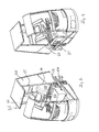
- FIGS. 2 to 5 show in perspective views a second embodiment of an electric motor, three-wheeled seat tractor, in the same components, as in the seat tractor off Fig. 1 , are provided with the same reference numerals.
- Fig. 2 shows the rear part 30 of the cab 26 in its retracted position.
- the rear part of the cab also has hinges 52 for a door (not shown) Inside, a battery compartment 56 can be seen, which receives the battery.
- the battery compartment 56 is covered by a battery cover 58 which surrounds and closes the battery compartment.
- the driver's seat 20 is attached.
- the rear part 30 of the driver's cab 26 is on the in Fig. 2 visible side of the seat tractor guided over a horizontally arranged guide rail 50.
- the rear part 30 has on the inside of its center strut 40 a lock 62 which engages behind the rail 50 in the closed position of the rear part and secures the rear part in its position.
- Fig. 2 to recognize that the rear part 30 is provided in the region of the car roof with protruding locking elements 64 to regulate the rear part 30 on the front part 28 in the closed position.
- Fig. 3 shows the seat tug Fig. 2 in a view from the other side.
- the rail 51 is portal-shaped on this side to allow lateral access to the battery compartment 56.
- the rear part 30 has a contour corresponding to the guide rail 51 66, which rests completely in the closed state of the driver's cab 51 on the guide rail.
- Fig. 4 shows the seat tug Fig. 2 in a view from behind.
- the guide rods 68 are rigidly connected to the rear part 30 and extend in the vehicle longitudinal direction.
- the guide rods 68 are attached to the rear transverse strut 46 at the ends.
- the drive part facing end of the guide rod is in an in Fig. 5 darg Whytress bearing block 70 out.
- the bearing block 70 is firmly connected to the drive part.
- the guide rod 68 has at its vehicle-side end a stop 72, which prevents withdrawal of the guide rod 68 from the bearing block 70.
- the guide rods 68 support the rear portion of the cab in the retracted position.
Landscapes
- Engineering & Computer Science (AREA)
- Transportation (AREA)
- Structural Engineering (AREA)
- Civil Engineering (AREA)
- Life Sciences & Earth Sciences (AREA)
- Geology (AREA)
- Mechanical Engineering (AREA)
- Body Structure For Vehicles (AREA)
- Arrangement Or Mounting Of Propulsion Units For Vehicles (AREA)
Abstract
Description
- Die vorliegende Erfindung betrifft ein Flurförderzeug mit einem Antriebsteil, das eine Fahrerkabine mit einem Fahrersitz und ein mit einer Batterieabdeckung verschlossenes Batteriefach aufweist.
- Flurförderzeuge, insbesondere elektromotorische Sitzschlepper, für einen Einsatz im Außenbereich mit einer Fahrerkabine auszustatten, ist bekannt. Bei solchen Fahrzeugen befindet sich die Batterie in dem Antriebsteil des Flurförderzeugs kurz vor dessen Antriebsachse und ist durch eine Batterieabdeckung, auf der der Fahrersitz positioniert ist, abgedeckt. Für ein Wechseln der Batterie, beispielsweise beim Mehrschichteinsatz des Fahrzeugs, ist es erforderlich, den Fahrersitz zur Seite zu klappen und die Abdeckung für das Batteriefach zu öffnen, um so die Batterie austauschen zu können. Die Abdeckung des Batteriefachs kann dabei als Batteriefachdeckel oder als Batteriehaube ausgebildet sein.
- Insbesondere bei einer fest montierten Fahrerkabine entstehen hierbei Platzprobleme, da einerseits der Fahrersitz zur Seite geklappt werden und andererseits ein freier Zugang zu dem Batteriefach bestehen muss, um die entladene Batterie entnehmen zu können und eine neue Batterie in das Batteriefach einzusetzen.
- Der Erfindung liegt die Aufgabe zugrunde, ein Flurförderzeug mit einer Fahrerkabine bereitzustellen, bei dem die Batterie unterhalb des Fahrersitzes angebracht ist, jedoch durch wenige Handgriffe und mit geringem Kraftaufwand ein freier Zugang zu dem Batteriefach hergestellt werden kann.
- Die Aufgabe wird durch ein Flurförderzeug mit den Merkmalen aus Anspruch 1 gelöst. Vorteilhafte Ausgestaltungen bilden den Gegenstand der Unteransprüche.
- Das erfindungsgemäße Flurförderzeug besitzt ein Antriebsteil, das eine Fahrerkabine mit einem Fahrersitz aufweist. Ferner ist das Antriebsteil mit einem Batteriefach ausgestattet, das von einer innerhalb der Fahrerkabine angeordneten Batterieabdeckung verschlossen wird.
- Das erfindungsgemäße Flurförderzeug besitzt eine Fahrerkabine mit einem feststehenden Frontteil und einem in Längsrichtung des Flurförderzeugs verschieblichen Heckteil. Das Antriebsteil weist eine Führung für das verschiebliche Heckteil auf. In seiner zurückgeschobenen Position gibt das Heckteil den Raum in der Fahrerkabine frei, um einen Batteriewechsel durchzuführen. Bei einem erfindungsgemäßen Flurförderzeug kann ein Zugang zu der Batterieabdeckung in der Fahrerkabine geschaffen werden, indem das Heckteil der Fahrerkabine heckseitig verschoben und somit zumindest der heckseitige Teil der Fahrerkabine freigegeben wird. Als besonders vorteilhaft an einem verschiebbaren Heckteil einer Fahrerkabine erweist sich, dass nur wenige Handgriffe erforderlich sind, um an die Batterieabdeckung zu gelangen. Zudem ist der Kraftaufwand für das Freilegen der Batterieabdeckung in der Fahrerkabine gering.
- In einer bevorzugten Ausgestaltung des erfindungsgemäßen Flurförderzeugs besitzt das Frontteil der Fahrerkabine zwei Säulen, die mit dem Antriebsteil starr verbunden sind. Das Frontteil ist derjenige Teil der Fahrerkabine, zu dem der Fahrersitz in einer für eine Benutzung durch den Fahrer vorgesehenen Position weist. Durch das feststehende Frontteil der Fahrerkabine ist der Teil, der für einen Zugang zum Batteriefach bewegt werden muss, kleiner, was den erforderlichen Kraftaufwand reduziert. Bevorzugt besitzt das Frontteil einen Übergang zu einem Dach der Fahrerkabine, so dass das verschiebliche Heckteil der Fahrerkabine nur einen Teil des Kabinendachs aufweist.
- In einer bevorzugten Weiterbildung des erfindungsgemäßen Flurförderzeugs weist das Heckteil vier Säulen auf, die einen Dach oder ein Teil des Dachs für die Fahrerkabine tragen. Die vier Säulen erstrecken sich im Wesentlichen vertikal und bilden eine die Fahrerkabine begrenzende Struktur.
- In einer bevorzugten Ausgestaltung sind die fahrzeugseitigen Enden der Säulen des Heckteils über Querstreben paarweise miteinander verbunden. Auf diese Weise werden die Säulen des Heckteils relativ zueinander versteift und das Heckteil der Fahrerkabine kann gleichmäßig und in sich stabil bleibend verschoben werden.
- In einer bevorzugten Weiterbildung weist die Führung für das Heckteil der Fahrerkabine geneigte Führungsschienen auf, die zur Hinterachse steigend an dem Antriebsteil angeordnet sind. Bei dieser Ausgestaltung wird das Heckteil der Fahrerkabine gegen die Neigung der Führungsschienen in seine geöffnete Position verschoben. Alternativ ist es auch möglich, die Führungsschiene horizontal anzuordnen, wodurch der Krafteinsatz beim Verschieben des Heckteils der Fahrerkabine weiter reduziert wird.
- In einer weiteren bevorzugten Ausgestaltung weist die Führung für das Heckteil der Fahrerkabine mindestens eine Führungsstange auf, die an dem Heckteil montiert ist und sich in Verschieberichtung des Heckteils erstreckt. Ferner ist die Führung mit einer Zylinderführung an dem Antriebsteil ausgestattet, in der die Führungsstange des Heckteils verschieblich angeordnet ist. Durch die Verwendung einer Führungsstange, die verschieblich in dem Antriebsteil des Flurförderzeugs gelagert ist, wird das Heckteil der Fahrerkabine in seiner zurückgeschobenen Position abgestützt. Insbesondere im Zusammenspiel mit Führungsschienen, die frontseitig von der Zylinderführung oder in dem Antriebsteil des Flurförderzeugs angeordnet sind, kann das Heckteil der Fahrerkabine beim Zurückschieben in seinem vorderen Bereich durch die Führungsschiene abgestützt und seitlich gesichert werden. Wird das Heckteil der Fahrerkabine weiter zurückgeschoben, wird es an seinem heckseitigen Ende durch die mindestens eine Führungsstange abgestützt.
- In einer bevorzugten Ausgestaltung ist in einer zurückgeschobenen Position des Heckteils der Fahrersitz umklappbar, so dass das Batteriefach für einen Austausch der Batterie freiliegt. Diese Ausgestaltung ist besonders dann vorteilhaft, wenn der Fahrersitz in der Fahrerkabine so montiert ist, dass seine Sitzfläche das Batteriefach ganz oder teilweise bedeckt. In dieser Ausgestaltung wird ein freier Zugang zum Batteriefach geschaffen, indem der Fahrersitz beiseite geklappt wird. Das Heckteil der Fahrerkabine wird hierfür ausreichend weit zurückgeschoben, um den Fahrersitz umzuklappen und das Batteriefach freizulegen. Hierbei kann der Fahrersitz zum Frontteil der Fahrerkabine hin oder zum Heckteil der Fahrerkabine geklappt werden. Auch kann ein Sitzteil und/oder ein Rückteil des Fahrersitzes geklappt werden.
- In einer bevorzugten Ausgestaltung ist das Flurförderzeug als ein elektromotorischer Sitzschlepper ausgebildet. Gerade bei einem Sitzschlepper wird häufig aus konstruktiven Gründen die Batteriefachabdeckung in der Fahrerkabine ganz oder teilweise durch den Fahrersitz verdeckt.
- Eine bevorzugte Ausgestaltung der Erfindung wird nachfolgend anhand eines Ausführungsbeispiels näher erläutert. Es zeigt:
- Fig. 1
- eine erste Ausgestaltung eines Sitzschleppers mit zurückgeschobenem Heckteil der Fahrerkabine in einer perspektivischen Ansicht und
- Fig. 2
- eine zweite Ausgestaltung eines Sitzschleppers mit geöffneter Batteriehaube in einer perspektivischen Ansicht von der Seite,
- Fig. 3
- den Sitzschlepper aus
Fig. 2 in einer perspektivischen Ansicht von der anderen Seite, - Fig. 4
- den Sitzschlepper aus
Fig. 2 in einer perspektivischen Ansicht von hinten und - Fig. 5
- eine Detailansicht der Führungsstange mit Lagerblock.
-
Fig. 1 zeigt einen elektromotorischen dreirädrigen Sitzschlepper 10, der ein Antriebsteil 12 besitzt. Die Erfindung kann selbstverständlich auch bei jedem anderen Flurförderzeug, das eine Fahrerkabine besitzt, verwirklicht werden. Der Antriebsteil 12 besitzt zwei angetriebene Hinterräder, von denen die Radlager 14 dargestellt sind und ein gelenktes Vorderrad 16. Die elektromotorischen Antriebe für das Fahrzeug befinden sich in dem Antriebsteil 12. Ferner besitzt das Antriebsteil 12 einen Aufbau 18, in dem das Batteriefach mit der Batterie angeordnet ist. An dem Aufbau 18 ist der Fahrersitz 20 vorgesehen, von dem aus ein Fahrer das Fahrzeug über ein Lenkrad 22 und weitere im Frontbereich angeordnete Bedienelemente 24 betätigen kann. Der Fahrersitz 20 ist auf einer Batteriefachhaube befestigt, über die das Batteriefach zugänglich ist. Die Batteriefachhaube bildet das Aufbauteil 18. - Der dargestellte Sitzschlepper 10 besitzt eine Fahrerkabine 26, die ein Frontteil 28 und ein Heckteil 30 aufweist. Das Frontteil 28 besitzt zwei parallel zueinander verlaufende Säulen 32, die im seitlichen Bereich einer Frontschürze 34 mit dem Antriebsteil oder dem Rahmen des Antriebsteils verbunden sind. Zwischen den Säulen 28 des Frontteils ist im Bereich des Kabinendachs eine Abdeckung 36 vorgesehen. Die Säulen 32 beschreiben im Bereich der Abdeckung 36 ungefähr eine 90°-Biegung, so dass die freien Enden 38 der Säulen 32 im Wesentlichen vertikal verlaufen.
- Je nach Ausgestaltung der Fahrerkabine kann zwischen den Säulen 32 unterhalb der Abdeckung 36 eine Frontscheibe vorgesehen sein.
- Das Heckteil 30 der Fahrerkabine besitzt ein Paar von Mittelsäulen 40 und ein Paar von Hecksäulen 42. Die Mittelsäulen 42 verlaufen im Wesentlichen vertikal. Die Hecksäulen 42 verlaufen ebenfalls ungefähr vertikal, besitzen allerdings in dem dargestellten Beispiel eine Neigung hin zu den Mittelsäulen 40. An ihrem fahrzeugseitigen Ende sind die Mittelsäule 40 und die Hecksäule 42 jeweils mit einer Querstrebe 44 miteinander verbunden. Ebenso ist zwischen dem fahrzeugseitigen Ende der Hecksäulen 42 eine Heckquerstrebe 46 angeordnet. An ihren zum Dach der Fahrerkabine weisenden Enden sind jeweils die Mittelstreben 40 mit der auf der entsprechenden Seite angeordneten Heckstrebe 42 über eine oben liegende Längsstrebe 48 miteinander verbunden. Die Längsstrebe 48 steht an ihrem zur Front der Fahrerkabine weisenden Ende über die Mittelstrebe 40 hervor. An ihrem heckseitigen Ende ist die Längsstrebe 48 endseitig mit der Hecksäule 42 verbunden.
- Die Fahrerkabine ist über eine auf jeder Seite an dem Antriebsteil 12 angeordnete Führungsschiene 50 in Fahrzeugslängsrichtung verschieblich. Das dargestellte Ausführungsbeispiel zeigt eine Führungsschiene 50, die im Bereich der Hinterräder 14 höher als im Frontbereich liegt. Hierdurch muss das Heckteil 26 der Fahrerkabine entgegen der Schwerkraft zurückgeschoben werden. Alternativ ist es auch möglich, die Führungsschiene 50 horizontal anzuordnen, wodurch der Kraftaufwand zum Zurückschieben des Heckteils verringert wird. In
Fig. 1 ist die zurückgeschobene - Position des Heckteils dargestellt. In dieser Position befindet sich die Mittelsäule 40 hecksseitig des Fahrersitzes 20, so dass ein freier Zugang zu dem Batteriefach unter dem Fahrersitz besteht. Bevorzugt sind Rastmittel in oder an der Führungsschiene 50 vorgesehen, die das Heckteil in seiner zurückgezogenen Position halten. Auch für die vorgeschobene Position (nicht dargestellt) können Rastmittel an oder in der Führungsschiene 50 vorgesehen sein, um ein unbeabsichtigtes Zurückschieben des Heckteils zu verhindern. Auch zwischen der Längsstrebe 48 und dem freien Ende des Frontteils 38 können Verbindungsmittel vorgesehen sein, die das Heckteil in seiner vorgeschobenen Position mit dem Frontteil im Bereich des Kabinendachs verbinden, um ein gegen herabstürzende Gegenstände sicherndes Dach zu bilden.
-
Fign. 2 bis 5 zeigen in perspektivischen Ansichten eine zweite Ausgestaltung eines elektromotorischen, dreirädrigen Sitzschlepper, bei dem gleiche Bauteile, wie in dem Sitzschlepper ausFig. 1 , mit gleichen Bezugszeichen versehen sind.Fig. 2 zeigt das Heckteil 30 der Fahrerkabine 26 in seiner zurückgeschobenen Position. Das Heckteil der Fahrerkabine besitzt zusätzlich Scharniere 52 für eine Tür (nicht dargestellt) Im Inneren ist ein Batteriefach 56 zu erkennen, das die Batterie aufnimmt. Das Batteriefach 56 wird durch eine Batteriehaube 58 verdeckt, die das Batteriefach umgibt und verschließt. Auf der Batteriehaube 58 ist der Fahrersitz 20 befestigt. Das Heckteil 30 der Fahrerkabine 26 ist auf der inFig. 2 sichtbaren Seite des Sitzschleppers über eine horizontal angeordnete Führungsschiene 50 geführt. Das Heckteil 30 besitzt auf der Innenseite seiner Mittelstrebe 40 eine Verriegelung 62, die in der geschlossenen Position des Heckteils die Schiene 50 hintergreift und das Heckteil in seiner Position sichert. - Ferner ist in
Fig. 2 zu erkennen, dass das Heckteil 30 im Bereich des Kabinendaches mit vorstehenden Verriegelungselementen 64 ausgestattet ist, um das Heckteil 30 an dem Frontteil 28 in der geschlossenen Position zu vernegeln. -
Fig. 3 zeigt den Sitzschlepper ausFig. 2 in einer Ansicht von der anderen Seite. Die Schiene 51 ist auf dieser Seite portalförmig ausgebildet, um einen seitlichen Zugang zu dem Batteriefach 56 zu erlauben. Das Heckteil 30 besitzt eine der Führungsschiene 51 entsprechende Kontur 66, die im geschlossenen Zustand der Fahrerkabine vollständig auf der Führungsschiene 51 aufliegt. -
Fig. 4 zeigt den Sitzschlepper ausFig. 2 in einer Ansicht von hinten. Deutlich zu erkennen sind zwei vorstehende Führungsstangen 68, die starr mit dem Heckteil 30 verbunden sind und sich in Fahrzeuglängsrichtung erstrecken. Die Führungsstangen 68 sind endseitig an der Heckquerstrebe 46 befestigt. Das zum Antriebsteil weisende Ende der Führungsstange ist in einem inFig. 5 dargstellten Lagerbock 70 geführt. Der Lagerbock 70 ist fest mit dem Antriebsteil verbunden. Die Führungsstange 68 besitzt an ihrem fahrzeugseitigen Ende einen Anschlag 72, der ein Herausziehen der Führungsstange 68 aus dem Lagerbock 70 verhindert. Die Führungsstangen 68 stützen das Heckteil der Fahrerkabine in der zurückgezogenen Position ab.
Claims (10)
- Flurförderzeug (10) mit einem Antriebsteil (12), das eine Fahrerkabine (26) mit einem Fahrersitz (20) und ein mit einer Batterieabdeckung verschlossenes Batteriefach (56) aufweist, dadurch gekennzeichnet, dass die Fahrerkabine (26) ein feststehendes Frontteil (28) und ein verschiebliches Heckteil (30) aufweist, und das Antriebsteil (12) eine Führung (50) für das verschiebliche Heckteil besitzt, um die Batterieabdeckung in der Fahrerkabine (26) in einer zurückgeschobenen Position des Heckteils für einen Batteriewechsel freizugeben.
- Flurförderzeug nach Anspruch 1, dadurch gekennzeichnet, dass das Frontteil (28) zwei Säulen (32) aufweist, die mit dem Antriebsteil (12) starr verbunden sind.
- Flurförderzeug nach Anspruch 2, dadurch gekennzeichnet, dass das Frontteil (28) einen Übergang zu einem Dach der Fahrerkabine (26) aufweist.
- Flurförderzeug nach einem der Ansprüche 1 bis 3, dadurch gekennzeichnet, dass das Heckteil (26) vier Säulen (40, 42) aufweist, die ein Dach oder einen Teil des Dachs für die Fahrerkabine (26) tragen.
- Flurförderzeug nach Anspruch 4, dadurch gekennzeichnet, dass die fahrzeugseitigen Enden der Säulen (42) des Heckteils (30) über Querstreben (40, 46) paarweise miteinander verbunden sind.
- Flurförderzeug nach einem der Ansprüche 1 bis 5, dadurch gekennzeichnet, dass die Führung (50) für das Heckteil (30) Führungsschienen aufweist, die geneigt zur Hinterachse ansteigend verlaufen.
- Flurförderzeug nach einem der Ansprüche 1 bis 5, dadurch gekennzeichnet, dass die Führung (50) für das Heckteil Führungsschienen aufweist, die im Wesentlichen horizontal verlaufen.
- Flurförderzeug nach einem der Ansprüche 1 bis 7, dadurch gekennzeichnet, dass die Führung mindestens eine Führungsstange aufweist, die an dem Heckteil montiert ist und sich in Verschieberichtung des Heckteils erstreckt, und dass die Führung ferner eine Zylinderführung an dem Antriebsteil aufweist, in der die Führungsstange des Heckteils verschieblich angeordnet ist.
- Flurförderzeug nach einem der Ansprüche 1 bis 8, dadurch gekennzeichnet, dass in einer zurückgeschobenen Position des Heckteils (30) der Fahrersitz (20) umklappbar ist und das Batteriefach freigibt.
- Flurförderzeug nach einem der Ansprüche 1 bis 9, dadurch gekennzeichnet, dass das Flurförderzeug als ein elektromotorischer Sitzschlepper ausgebildet ist.
Applications Claiming Priority (1)
| Application Number | Priority Date | Filing Date | Title |
|---|---|---|---|
| DE201110100918 DE102011100918A1 (de) | 2011-04-29 | 2011-04-29 | Flugförderzeug mit einer Fahrerkabine |
Publications (2)
| Publication Number | Publication Date |
|---|---|
| EP2518001A1 true EP2518001A1 (de) | 2012-10-31 |
| EP2518001B1 EP2518001B1 (de) | 2013-07-10 |
Family
ID=45999534
Family Applications (1)
| Application Number | Title | Priority Date | Filing Date |
|---|---|---|---|
| EP20120002555 Active EP2518001B1 (de) | 2011-04-29 | 2012-04-11 | Flurförderzeug mit einer Fahrerkabine |
Country Status (2)
| Country | Link |
|---|---|
| EP (1) | EP2518001B1 (de) |
| DE (1) | DE102011100918A1 (de) |
Citations (4)
| Publication number | Priority date | Publication date | Assignee | Title |
|---|---|---|---|---|
| US3610359A (en) * | 1969-11-17 | 1971-10-05 | Hyster Co | Truck with movable control panel |
| DE3127019A1 (de) * | 1981-07-09 | 1983-01-27 | Jungheinrich Unternehmensverwaltung Kg, 2000 Hamburg | "vorrichtung fuer einen submast-hublader mit in fahrzeugrichtung laengsbeweglich gehaltenem batteriewagen" |
| DE4138834A1 (de) * | 1991-11-26 | 1993-05-27 | Linde Ag | Flurfoerderzeug mit einer schwenkbaren lenkanordnung |
| JP2005298188A (ja) * | 2004-04-15 | 2005-10-27 | Toyota Industries Corp | フォークリフト、及びフォークリフトの内部部品のメンテナンス方法 |
Family Cites Families (6)
| Publication number | Priority date | Publication date | Assignee | Title |
|---|---|---|---|---|
| GB1426056A (en) * | 1972-04-17 | 1976-02-25 | Lancer Boss Ltd | Fork lift trucks |
| JP2001302192A (ja) * | 2000-04-20 | 2001-10-31 | Nippon Yusoki Co Ltd | フォークリフト |
| DE10114571A1 (de) * | 2001-03-24 | 2002-09-26 | Jungheinrich Ag | Batterie-elektrisch betriebenes Flurförderzeug, insbesondere Gegengewichtsstapler |
| WO2003022725A1 (en) * | 2001-09-12 | 2003-03-20 | Petrus Johannes Albertus Radyn | Lifting and transfer device for heavy objects |
| DE102006031461A1 (de) * | 2006-07-07 | 2008-01-10 | Jungheinrich Aktiengesellschaft | Batteriewechselsystem für ein batteriebetriebenes Flurförderzeug |
| DE102007025203A1 (de) * | 2007-05-30 | 2008-12-04 | Linde Material Handling Gmbh | Elektro-Gabelstapler mit Hubgerüst und seitenverschiebbarem Stützkörper |
-
2011
- 2011-04-29 DE DE201110100918 patent/DE102011100918A1/de not_active Withdrawn
-
2012
- 2012-04-11 EP EP20120002555 patent/EP2518001B1/de active Active
Patent Citations (4)
| Publication number | Priority date | Publication date | Assignee | Title |
|---|---|---|---|---|
| US3610359A (en) * | 1969-11-17 | 1971-10-05 | Hyster Co | Truck with movable control panel |
| DE3127019A1 (de) * | 1981-07-09 | 1983-01-27 | Jungheinrich Unternehmensverwaltung Kg, 2000 Hamburg | "vorrichtung fuer einen submast-hublader mit in fahrzeugrichtung laengsbeweglich gehaltenem batteriewagen" |
| DE4138834A1 (de) * | 1991-11-26 | 1993-05-27 | Linde Ag | Flurfoerderzeug mit einer schwenkbaren lenkanordnung |
| JP2005298188A (ja) * | 2004-04-15 | 2005-10-27 | Toyota Industries Corp | フォークリフト、及びフォークリフトの内部部品のメンテナンス方法 |
Also Published As
| Publication number | Publication date |
|---|---|
| EP2518001B1 (de) | 2013-07-10 |
| DE102011100918A1 (de) | 2012-10-31 |
| DE102011100918A8 (de) | 2013-01-03 |
Similar Documents
| Publication | Publication Date | Title |
|---|---|---|
| DE102007006722B4 (de) | Träger für eine Karosserie eines Kraftwagens | |
| AT240192B (de) | Fahrerhausauftritt, insbesondere für Nutzkraftwagen | |
| DE102012000790A1 (de) | Fahrzeugaufbauvorderstruktur und Verfahren zum Herstellen derselben | |
| EP1897761A2 (de) | Kraftfahrzeug mit einer Überrollbügelanordnung | |
| DE2809379C2 (de) | Dachaufbau für Kraftfahrzeuge, insbesondere Personenwagen, mit einem einen Rahmenboden aufweisenden Schiebedach | |
| EP2657111B1 (de) | Fahrerhauslagerung | |
| DE102007052976A1 (de) | Flurförderzeug mit einem zur Aufnahme eines Batterieblocks ausgebildeten Tragabschnitt und einem schwenkbaren Längsträger | |
| EP1832499A2 (de) | Militärisches Kraftfahrzeug zum Mannschaftstransport | |
| EP3668776B1 (de) | Vorbaustrukturanordnung für einen kraftwagenrohbau sowie aggregateträger für eine derartige vorbaustrukturanordnung | |
| DE10332508A1 (de) | Fahrerhaus für ein Nutzfahrzeug | |
| DE2741125A1 (de) | Lastkraftwagen, insbesondere grossraumfahrzeug oder sattelschlepper | |
| EP2518001B1 (de) | Flurförderzeug mit einer Fahrerkabine | |
| DE102009033802A1 (de) | Sitzanlage für einen Innenraum eines Kraftwagens | |
| DE102014008805B4 (de) | Dachstruktur für ein Fahrzeug | |
| EP2580106A1 (de) | Lenkungsdurchführung für militärisches fahrzeug | |
| DE2318614C3 (de) | Einstiegsverkleidung an Wetterverdecken und Fahrerhäusern von Nutzfahrzeugen | |
| DE102014215459B4 (de) | Karosserie eines Cabriolets | |
| DE102007022551A1 (de) | Überrollschutzsystem | |
| DE102013216499B4 (de) | Klappe für einen Kraftwagen | |
| DE102021006770B4 (de) | Nutzfahrzeug mit Ladesteckdose | |
| DE102021006774B4 (de) | Nutzfahrzeug mit Ladesteckdose | |
| DE102021006771B4 (de) | Nutzfahrzeug mit Ladesteckdose | |
| WO2009015756A1 (de) | Heckklappenanordnung für einen personenkraftwagen | |
| DE102010005367A1 (de) | Karosseriestruktur mit Adsorptionsmaterial | |
| DE102024112235A1 (de) | Kraftfahrzeug mit horizontal geteilter Tür |
Legal Events
| Date | Code | Title | Description |
|---|---|---|---|
| PUAI | Public reference made under article 153(3) epc to a published international application that has entered the european phase |
Free format text: ORIGINAL CODE: 0009012 |
|
| 17P | Request for examination filed |
Effective date: 20120823 |
|
| AK | Designated contracting states |
Kind code of ref document: A1 Designated state(s): AL AT BE BG CH CY CZ DE DK EE ES FI FR GB GR HR HU IE IS IT LI LT LU LV MC MK MT NL NO PL PT RO RS SE SI SK SM TR |
|
| AX | Request for extension of the european patent |
Extension state: BA ME |
|
| RIC1 | Information provided on ipc code assigned before grant |
Ipc: B66F 9/075 20060101AFI20130211BHEP |
|
| GRAP | Despatch of communication of intention to grant a patent |
Free format text: ORIGINAL CODE: EPIDOSNIGR1 |
|
| INTG | Intention to grant announced |
Effective date: 20130326 |
|
| GRAS | Grant fee paid |
Free format text: ORIGINAL CODE: EPIDOSNIGR3 |
|
| GRAA | (expected) grant |
Free format text: ORIGINAL CODE: 0009210 |
|
| AK | Designated contracting states |
Kind code of ref document: B1 Designated state(s): AL AT BE BG CH CY CZ DE DK EE ES FI FR GB GR HR HU IE IS IT LI LT LU LV MC MK MT NL NO PL PT RO RS SE SI SK SM TR |
|
| REG | Reference to a national code |
Ref country code: GB Ref legal event code: FG4D Free format text: NOT ENGLISH |
|
| REG | Reference to a national code |
Ref country code: AT Ref legal event code: REF Ref document number: 620878 Country of ref document: AT Kind code of ref document: T Effective date: 20130715 Ref country code: CH Ref legal event code: EP |
|
| REG | Reference to a national code |
Ref country code: IE Ref legal event code: FG4D Free format text: LANGUAGE OF EP DOCUMENT: GERMAN |
|
| REG | Reference to a national code |
Ref country code: DE Ref legal event code: R096 Ref document number: 502012000042 Country of ref document: DE Effective date: 20130912 |
|
| REG | Reference to a national code |
Ref country code: SE Ref legal event code: TRGR |
|
| PG25 | Lapsed in a contracting state [announced via postgrant information from national office to epo] |
Ref country code: SI Free format text: LAPSE BECAUSE OF FAILURE TO SUBMIT A TRANSLATION OF THE DESCRIPTION OR TO PAY THE FEE WITHIN THE PRESCRIBED TIME-LIMIT Effective date: 20130710 |
|
| REG | Reference to a national code |
Ref country code: NL Ref legal event code: VDEP Effective date: 20130710 |
|
| REG | Reference to a national code |
Ref country code: LT Ref legal event code: MG4D |
|
| PG25 | Lapsed in a contracting state [announced via postgrant information from national office to epo] |
Ref country code: CY Free format text: LAPSE BECAUSE OF FAILURE TO SUBMIT A TRANSLATION OF THE DESCRIPTION OR TO PAY THE FEE WITHIN THE PRESCRIBED TIME-LIMIT Effective date: 20130918 Ref country code: NO Free format text: LAPSE BECAUSE OF FAILURE TO SUBMIT A TRANSLATION OF THE DESCRIPTION OR TO PAY THE FEE WITHIN THE PRESCRIBED TIME-LIMIT Effective date: 20131010 Ref country code: PT Free format text: LAPSE BECAUSE OF FAILURE TO SUBMIT A TRANSLATION OF THE DESCRIPTION OR TO PAY THE FEE WITHIN THE PRESCRIBED TIME-LIMIT Effective date: 20131111 Ref country code: LT Free format text: LAPSE BECAUSE OF FAILURE TO SUBMIT A TRANSLATION OF THE DESCRIPTION OR TO PAY THE FEE WITHIN THE PRESCRIBED TIME-LIMIT Effective date: 20130710 Ref country code: HR Free format text: LAPSE BECAUSE OF FAILURE TO SUBMIT A TRANSLATION OF THE DESCRIPTION OR TO PAY THE FEE WITHIN THE PRESCRIBED TIME-LIMIT Effective date: 20130710 Ref country code: IS Free format text: LAPSE BECAUSE OF FAILURE TO SUBMIT A TRANSLATION OF THE DESCRIPTION OR TO PAY THE FEE WITHIN THE PRESCRIBED TIME-LIMIT Effective date: 20131110 |
|
| PG25 | Lapsed in a contracting state [announced via postgrant information from national office to epo] |
Ref country code: GR Free format text: LAPSE BECAUSE OF FAILURE TO SUBMIT A TRANSLATION OF THE DESCRIPTION OR TO PAY THE FEE WITHIN THE PRESCRIBED TIME-LIMIT Effective date: 20131011 Ref country code: FI Free format text: LAPSE BECAUSE OF FAILURE TO SUBMIT A TRANSLATION OF THE DESCRIPTION OR TO PAY THE FEE WITHIN THE PRESCRIBED TIME-LIMIT Effective date: 20130710 Ref country code: LV Free format text: LAPSE BECAUSE OF FAILURE TO SUBMIT A TRANSLATION OF THE DESCRIPTION OR TO PAY THE FEE WITHIN THE PRESCRIBED TIME-LIMIT Effective date: 20130710 Ref country code: PL Free format text: LAPSE BECAUSE OF FAILURE TO SUBMIT A TRANSLATION OF THE DESCRIPTION OR TO PAY THE FEE WITHIN THE PRESCRIBED TIME-LIMIT Effective date: 20130710 Ref country code: NL Free format text: LAPSE BECAUSE OF FAILURE TO SUBMIT A TRANSLATION OF THE DESCRIPTION OR TO PAY THE FEE WITHIN THE PRESCRIBED TIME-LIMIT Effective date: 20130710 Ref country code: ES Free format text: LAPSE BECAUSE OF FAILURE TO SUBMIT A TRANSLATION OF THE DESCRIPTION OR TO PAY THE FEE WITHIN THE PRESCRIBED TIME-LIMIT Effective date: 20131021 |
|
| PG25 | Lapsed in a contracting state [announced via postgrant information from national office to epo] |
Ref country code: CY Free format text: LAPSE BECAUSE OF FAILURE TO SUBMIT A TRANSLATION OF THE DESCRIPTION OR TO PAY THE FEE WITHIN THE PRESCRIBED TIME-LIMIT Effective date: 20130710 |
|
| PG25 | Lapsed in a contracting state [announced via postgrant information from national office to epo] |
Ref country code: CZ Free format text: LAPSE BECAUSE OF FAILURE TO SUBMIT A TRANSLATION OF THE DESCRIPTION OR TO PAY THE FEE WITHIN THE PRESCRIBED TIME-LIMIT Effective date: 20130710 Ref country code: SK Free format text: LAPSE BECAUSE OF FAILURE TO SUBMIT A TRANSLATION OF THE DESCRIPTION OR TO PAY THE FEE WITHIN THE PRESCRIBED TIME-LIMIT Effective date: 20130710 Ref country code: EE Free format text: LAPSE BECAUSE OF FAILURE TO SUBMIT A TRANSLATION OF THE DESCRIPTION OR TO PAY THE FEE WITHIN THE PRESCRIBED TIME-LIMIT Effective date: 20130710 Ref country code: RO Free format text: LAPSE BECAUSE OF FAILURE TO SUBMIT A TRANSLATION OF THE DESCRIPTION OR TO PAY THE FEE WITHIN THE PRESCRIBED TIME-LIMIT Effective date: 20130710 Ref country code: DK Free format text: LAPSE BECAUSE OF FAILURE TO SUBMIT A TRANSLATION OF THE DESCRIPTION OR TO PAY THE FEE WITHIN THE PRESCRIBED TIME-LIMIT Effective date: 20130710 |
|
| PLBE | No opposition filed within time limit |
Free format text: ORIGINAL CODE: 0009261 |
|
| STAA | Information on the status of an ep patent application or granted ep patent |
Free format text: STATUS: NO OPPOSITION FILED WITHIN TIME LIMIT |
|
| 26N | No opposition filed |
Effective date: 20140411 |
|
| REG | Reference to a national code |
Ref country code: DE Ref legal event code: R097 Ref document number: 502012000042 Country of ref document: DE Effective date: 20140411 |
|
| PG25 | Lapsed in a contracting state [announced via postgrant information from national office to epo] |
Ref country code: LU Free format text: LAPSE BECAUSE OF FAILURE TO SUBMIT A TRANSLATION OF THE DESCRIPTION OR TO PAY THE FEE WITHIN THE PRESCRIBED TIME-LIMIT Effective date: 20140411 Ref country code: MC Free format text: LAPSE BECAUSE OF FAILURE TO SUBMIT A TRANSLATION OF THE DESCRIPTION OR TO PAY THE FEE WITHIN THE PRESCRIBED TIME-LIMIT Effective date: 20130710 |
|
| REG | Reference to a national code |
Ref country code: IE Ref legal event code: MM4A |
|
| PG25 | Lapsed in a contracting state [announced via postgrant information from national office to epo] |
Ref country code: IE Free format text: LAPSE BECAUSE OF NON-PAYMENT OF DUE FEES Effective date: 20140411 |
|
| REG | Reference to a national code |
Ref country code: CH Ref legal event code: PL |
|
| PG25 | Lapsed in a contracting state [announced via postgrant information from national office to epo] |
Ref country code: LI Free format text: LAPSE BECAUSE OF NON-PAYMENT OF DUE FEES Effective date: 20150430 Ref country code: CH Free format text: LAPSE BECAUSE OF NON-PAYMENT OF DUE FEES Effective date: 20150430 |
|
| PG25 | Lapsed in a contracting state [announced via postgrant information from national office to epo] |
Ref country code: MT Free format text: LAPSE BECAUSE OF FAILURE TO SUBMIT A TRANSLATION OF THE DESCRIPTION OR TO PAY THE FEE WITHIN THE PRESCRIBED TIME-LIMIT Effective date: 20130710 |
|
| REG | Reference to a national code |
Ref country code: FR Ref legal event code: PLFP Year of fee payment: 5 |
|
| PG25 | Lapsed in a contracting state [announced via postgrant information from national office to epo] |
Ref country code: SM Free format text: LAPSE BECAUSE OF FAILURE TO SUBMIT A TRANSLATION OF THE DESCRIPTION OR TO PAY THE FEE WITHIN THE PRESCRIBED TIME-LIMIT Effective date: 20130710 |
|
| PG25 | Lapsed in a contracting state [announced via postgrant information from national office to epo] |
Ref country code: RS Free format text: LAPSE BECAUSE OF FAILURE TO SUBMIT A TRANSLATION OF THE DESCRIPTION OR TO PAY THE FEE WITHIN THE PRESCRIBED TIME-LIMIT Effective date: 20130710 Ref country code: BG Free format text: LAPSE BECAUSE OF FAILURE TO SUBMIT A TRANSLATION OF THE DESCRIPTION OR TO PAY THE FEE WITHIN THE PRESCRIBED TIME-LIMIT Effective date: 20130710 |
|
| PG25 | Lapsed in a contracting state [announced via postgrant information from national office to epo] |
Ref country code: HU Free format text: LAPSE BECAUSE OF FAILURE TO SUBMIT A TRANSLATION OF THE DESCRIPTION OR TO PAY THE FEE WITHIN THE PRESCRIBED TIME-LIMIT; INVALID AB INITIO Effective date: 20120411 Ref country code: TR Free format text: LAPSE BECAUSE OF FAILURE TO SUBMIT A TRANSLATION OF THE DESCRIPTION OR TO PAY THE FEE WITHIN THE PRESCRIBED TIME-LIMIT Effective date: 20130710 Ref country code: BE Free format text: LAPSE BECAUSE OF FAILURE TO SUBMIT A TRANSLATION OF THE DESCRIPTION OR TO PAY THE FEE WITHIN THE PRESCRIBED TIME-LIMIT Effective date: 20140430 |
|
| REG | Reference to a national code |
Ref country code: FR Ref legal event code: PLFP Year of fee payment: 6 |
|
| REG | Reference to a national code |
Ref country code: FR Ref legal event code: PLFP Year of fee payment: 7 |
|
| REG | Reference to a national code |
Ref country code: AT Ref legal event code: MM01 Ref document number: 620878 Country of ref document: AT Kind code of ref document: T Effective date: 20170411 |
|
| PG25 | Lapsed in a contracting state [announced via postgrant information from national office to epo] |
Ref country code: MK Free format text: LAPSE BECAUSE OF FAILURE TO SUBMIT A TRANSLATION OF THE DESCRIPTION OR TO PAY THE FEE WITHIN THE PRESCRIBED TIME-LIMIT Effective date: 20130710 |
|
| PG25 | Lapsed in a contracting state [announced via postgrant information from national office to epo] |
Ref country code: AT Free format text: LAPSE BECAUSE OF NON-PAYMENT OF DUE FEES Effective date: 20170411 |
|
| PG25 | Lapsed in a contracting state [announced via postgrant information from national office to epo] |
Ref country code: AL Free format text: LAPSE BECAUSE OF FAILURE TO SUBMIT A TRANSLATION OF THE DESCRIPTION OR TO PAY THE FEE WITHIN THE PRESCRIBED TIME-LIMIT Effective date: 20130710 |
|
| PGFP | Annual fee paid to national office [announced via postgrant information from national office to epo] |
Ref country code: DE Payment date: 20250417 Year of fee payment: 14 |
|
| PGFP | Annual fee paid to national office [announced via postgrant information from national office to epo] |
Ref country code: IT Payment date: 20250430 Year of fee payment: 14 |
|
| PGFP | Annual fee paid to national office [announced via postgrant information from national office to epo] |
Ref country code: FR Payment date: 20250422 Year of fee payment: 14 |
|
| PGFP | Annual fee paid to national office [announced via postgrant information from national office to epo] |
Ref country code: SE Payment date: 20250423 Year of fee payment: 14 |
|
| PGFP | Annual fee paid to national office [announced via postgrant information from national office to epo] |
Ref country code: GB Payment date: 20260324 Year of fee payment: 15 |