EP2517543A2 - Machine agricole - Google Patents
Machine agricole Download PDFInfo
- Publication number
- EP2517543A2 EP2517543A2 EP12002876A EP12002876A EP2517543A2 EP 2517543 A2 EP2517543 A2 EP 2517543A2 EP 12002876 A EP12002876 A EP 12002876A EP 12002876 A EP12002876 A EP 12002876A EP 2517543 A2 EP2517543 A2 EP 2517543A2
- Authority
- EP
- European Patent Office
- Prior art keywords
- attachment
- scanning
- detected
- laser measuring
- agricultural machine
- Prior art date
- Legal status (The legal status is an assumption and is not a legal conclusion. Google has not performed a legal analysis and makes no representation as to the accuracy of the status listed.)
- Granted
Links
Images

Classifications
-
- A—HUMAN NECESSITIES
- A01—AGRICULTURE; FORESTRY; ANIMAL HUSBANDRY; HUNTING; TRAPPING; FISHING
- A01B—SOIL WORKING IN AGRICULTURE OR FORESTRY; PARTS, DETAILS, OR ACCESSORIES OF AGRICULTURAL MACHINES OR IMPLEMENTS, IN GENERAL
- A01B69/00—Steering of agricultural machines or implements; Guiding agricultural machines or implements on a desired track
- A01B69/007—Steering or guiding of agricultural vehicles, e.g. steering of the tractor to keep the plough in the furrow
- A01B69/008—Steering or guiding of agricultural vehicles, e.g. steering of the tractor to keep the plough in the furrow automatic
-
- A—HUMAN NECESSITIES
- A01—AGRICULTURE; FORESTRY; ANIMAL HUSBANDRY; HUNTING; TRAPPING; FISHING
- A01B—SOIL WORKING IN AGRICULTURE OR FORESTRY; PARTS, DETAILS, OR ACCESSORIES OF AGRICULTURAL MACHINES OR IMPLEMENTS, IN GENERAL
- A01B69/00—Steering of agricultural machines or implements; Guiding agricultural machines or implements on a desired track
- A01B69/001—Steering by means of optical assistance, e.g. television cameras
Definitions
- the present invention relates to an agricultural machine with an attachment for growing various implements for Erntegut- and / or soil cultivation, a ground detection device for contactless detection of a soil and / or Erntegutkontur, and a control device for controlling the agricultural machine and / or the attachment in dependence the detected soil and / or Erntegutkontur, wherein the soil detection device comprises at least one laser measuring device, the laser beam for scanning the soil and / or Erntegutkontur is feasible over a scanning range.
- the DE 198 59 875 A1 a haymaking machine, on which a capacitive or after the Doppler effect sensor is provided by means of which not directly the soil surface itself, but a lying Erntegutschwad to be detected in order to raise the working organs of the haymaking machine, if said sensor Randschwad which is not to be processed by the working bodies.
- the EP 18 13 142 B1 further proposes an agricultural machine, in which an acoustic scanning sensor emits scanning signals in different frequencies, in order to detect the contour of the ground itself on the one hand and the contour of a Erntegutschwads lying on the other. In this way, on the one hand, the height adjustment of the pickup in dependence on the detected ground contour and on the other hand, the drive power of the pickup can be varied depending on the detected swath volume.
- the laser signal is in this case reflected at a respective contour point, whereby the distance of the contour point can be determined by means of a transit time measurement, from which in conjunction with the known geometry data of the inclination angle of the laser beam to the horizontal, the deflection angle of the laser beam with respect to a vertical plane extending in the direction of travel and the Mounting height of the laser measuring device, the exact position of the respective contour point can be determined.
- the soil or Erntegutkontur to be recorded for the respective agricultural task can be arranged in different areas.
- the cutting edge to be observed during mowing is usually clearly offset to the side next to the tractor, while the Erntegutschwad to be detected for a baler or a loading wagon is usually centrally located in the lane of the tractor.
- the scanning range of the laser measuring device is adjusted to be sufficiently wide in order to be able to record these differently positioned soil or crop contours for different tasks, very large amounts of data accumulate, which have to be processed by the evaluation device.
- the detection speed suffers, so that at higher speeds no sufficiently fast intervention in the steering of the tractor or the control of the operating parameters of the implement can be guaranteed.
- the scanning range is set further forward, ie with a greater front distance, a very flat scanning angle with respect to the horizontal results at a limited mounting height of the laser measuring device, as a result of which the scanned contours are greatly distorted, similar to an oblique cut.
- the present invention is therefore based on the object to provide an improved agricultural machine of the type mentioned, which avoids the disadvantages of the prior art and further develops the latter in an advantageous manner.
- an improved soil or crop contour scanning by means of a laser beam is to be achieved, which has a sufficiently large scanning area in order to be able to precisely record differently shaped and positioned soil or crop contours for different implements, without causing excessive amounts of data.
- a detection device is provided for detecting the attachment attached to the attachment device, wherein the scanning range of the laser measuring device is set by an adjustment device as a function of the respectively detected attachment.
- the laser measuring device is associated with an intelligent control system, which knows for different attachments, where in each case the observed floor contour section and the laser measuring device accordingly controls in terms of their scanning so that the scanning specifically for the respective attachment fits.
- a data bus can be provided, by means of which implement identification data and setting data can be transmitted.
- the detection device for detecting the respectively attached attachment, the adjusting device for adjusting the scanning range of the laser measuring device and the control system communicate with each other via data bus.
- the detection of the respective attachment for presetting the scanning range of the laser measuring device can basically be done in various ways.
- the detection can be carried out without contact, wherein the detection device may have a reading device for attaching attachable to the attachment data memory, for example in the form of a transponder chip, wherein in said data storage attachment identification data and / or setting data for the laser measuring device can be stored.
- the data is transferred from the attached to the attachment data storage device to the reading device, wherein based on the transmitted identification data and / or setting data, the setting the preset range of the laser measuring device accordingly.
- a barcode reader which can read in a barcode attached to the attachment.
- other data storage and transmission means may be provided.
- manual or semi-automatic attachment detection can also be provided, for example such that the setting device for setting the scanning range of the laser measuring device has an input device, for example in the form of a touch screen, a keyboard or a magnetic stripe reader, into which a data card plugged in or on which such a data card must be pulled past.
- Such a manual input option for the implement identification data can also be provided in addition to the above-described automatic detection, for example in order to be able to make a default setting of the laser scanning range in the event of data transmission problems.
- the default setting of the laser beam scanning range can basically be done in various ways. Depending on the design of the laser scanner, it may be advantageous, for example, to have a horizontal and / or vertical angle range, in which the laser measuring device scans the soil or Erntegutteppich to restrict so as to hide unrecognizable areas and thereby significantly reduce the amount of data.
- the restriction of the scanning angle ranges or the blanking of unusable ranges can advantageously be effected by software, for example by blanking or filtering out the scan data provided in a region which is not required. As a result, computing time and bus capacity can be saved.
- a laser measuring device which operates with a scanning angle of 70 ° and can record different tilt angles to the horizontal by means of tiltable mirrors, by way of example only a section of, for example, 35 ° of the mentioned scanning angle range of, for example, 70 ° can be used and of the several horizontal Scanning angles, for example, only one used for the evaluation, while the rest is hidden or filtered out.
- the angle of inclination of the laser beam relative to the horizontal can be varied by the setting device in dependence on the respectively detected attachment such that the scanning range for a driven at a higher driving speed attachment viewed in the direction of travel lying ahead and less for an operated at a lower driving speed attachment is placed far in front. If, for example, a loader wagon is mounted, with which it is possible to drive quite quickly, the laser measuring device is pre-set to look relatively far forward with the laser beam and to scan a swath section lying relatively far in front of the machine.
- the laser measuring device is preset in such a way based on the recorded data of the baler that the scanning is closer to the tractor or less far from the tractor to achieve a higher accuracy of contour scanning with sufficient lead time.
- the scanning range of the laser measuring device can also be preset differently with regard to its scanning width and / or with regard to its position transversely to the traffic lane, depending on which attachment is used. If, for example, a loading wagon is mounted which has a large receiving width at the pickup, the laser measuring device can be preset in such a way that a relatively wide area in the lane in front of the tractor or loader wagon is detected by the laser measuring device. Since a correspondingly wide swath usually lies in the lane of the tractor, the scanning beam of the laser measuring device is reciprocated over a fairly large width, the scanning area being provided substantially in the lane of the tractor.
- the laser measuring device does not necessarily have to be directed to a respective soil or crop contour that is currently being processed.
- the laser measuring device is set so that a not to be machined field section is scanned, in particular one next to the processed Trunk lying field section, which was previously processed in a previous tram. Namely, there are often easier-to-grasp contours, for example, when crop was stored in a swath.
- the size of the transverse offset of Scanning range is set away from the center of the lane of the machine depending on the respectively detected attachment.
- the detected identification data and / or setting data for the respective attachment information about the working width and / or the lateral projection of the respective attachment so that the control for the laser measuring device knows how far with correct connection driving a previously generated crop contour, for example in the form of a swath or a generated bottom contour would have to be arranged laterally spaced, for example in the form of a furrow.
- the width of the scanning range can also be preset accordingly. If, for example, a rake is being cultivated, the laser measuring device can detect the area in which a windrow deposited on the previously traveled lane lies, because the controller knows how far to the side of the windrow must lie from the detected working width of the rake and the known, commonly stored swath position , if correctly driven on connection.
- the scanning is set depending on the respectively detected attachment to a scan width which is less than 150% of the working width of the attachment.
- the scan width can also be set to less than 75% of the working width of the mounted implement. If, for example, a loader wagon is mounted, the scanning width of the laser beam is advantageously set to a range of approximately 100% to 150% of the width of the pickup of the wagon, since it accommodates correspondingly broad crop swaths can be.
- the sampling width can be set much smaller than the working width of the mower because the crop edge is usually sharply demarcated and can vary only in a small area in terms of their location, the only a fraction of the working width of the mower.
- the scan width of the laser beam it may be sufficient to set the scan width of the laser beam to less than 50% of the working width of the attachment machine.
- the setting device for setting the scanning range of the laser measuring device can basically determine the default settings in various ways.
- the scanning ranges can be calculated from the identification data and associated information about the working width of the respective attachment.
- the setting device can also have a data memory or be connectable to such a data memory by means of a data transmission device in order to read from the data memory for a respective attachment associated default data and to use for setting the scanning range.
- a plurality of data sets for the aforementioned preset data of different attachments can advantageously be stored here, so that when a respectively coupled attachment is detected, only the appropriate preset data has to be read from the data memory in order to obtain the scan range of the Set the laser measuring device for the respective implement correctly.
- a power steering device may be provided which provides a steering signal in dependence on the ground or crop contour respectively determined by the laser measuring device and its position relative to the agricultural machine in order to be able to act on the said machine To be able to drive along the soil or crop contour.
- said steering signal may, for example, be a signal displayed on a display, for example in the form of an arrow pointing to the right or left, on the basis of which the tractor operator sees whether he has to steer to the right or left.
- the steering signal may also be a drive signal for an automatically operating steering device which automatically controls the steering angle of the agricultural machine as a function of said steering signal.
- the power steering device advantageously comprises an evaluation device which generates the steering signal as a function of the respectively grasped attachment and its working width as well as the detected position of the ground or crop contour.
- a machining edge can be scanned from an already processed area of the field from an earlier tram and used in the aforementioned manner. For example, when installing a rake a windrow stored in a previous lane, which is when driving the current tram next to the agricultural machine and its working width, detected and used for the steering signal, so that the agricultural machine at a predetermined distance laterally next to said Schwad drives along.
- the loosened crop carpet can be scanned, which has been loosened in a previous lane, in particular, the transition between the already loosened feed carpet area and the not yet loosened feed carpet area can be determined.
- the steering signal can be generated in such a way that the current tramline is placed so that the working width of the tentter overlaps slightly with the already loosened area, on the one hand to use the working width of the tentter as completely as possible, but on the other hand to achieve complete tedding without unprocessed transition areas ,
- variable laser measuring device can also be used in dependence on the detected soil and / or crop contour, its size and / or condition and / or position at least control another machine or attachment operating parameters, such as a rotational speed of a working rotor, a working height of a working unit or the power supply to a drive or the driving speed.
- the evaluation of the data provided by the laser measuring device and the functions and commands derived therefrom can be varied depending on the respectively detected or identified attachment.
- an evaluation unit of the control device can evaluate the data provided by the laser measuring device to determine a swath contour and / or the cross-sectional profile of the scanned crop regions, for example to adapt the performance and picking speed of the pickup truck to the loader depending thereon ,
- the contour of the crop or its cross-sectional profile is less interesting, so that the evaluation of the detection device can be informed that the data evaluation is omitted with respect to the contour profile and instead determined only a Mähkante and / or the grass height becomes.
- the arithmetic operations to be performed and the required data capacities can be significantly reduced.
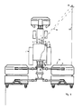
- the agricultural machine may include a tractor 1, which has a hitch 2 to grow various attachments 3 can.
- the hitch 2 can both rear side and front side each have a mounting unit, for example in the form of a three-point linkage include in order to be able to grow attachments both on the rear and on the front.
- the attachment 3 comprises a mowing machine 4, which comprises a front mower mounted on the front side and two rear mowers mounted laterally and projecting laterally.
- Conditioners or a cross-conveyor may be associated with the rear mowers in order to be able to deposit the crop cut down by the lateral mowers transversely to a central swath.
- a detection device 16 which detects automatic, which attachment is attached to the tractor 1.
- Said detection device 16 may in this case comprise a non-contact, for example in the radio frequency range transmitting / receiving device with a reader 18 to read from a data memory 19 which is attached to the attachment 3, data to identify said device and / / or to be able to set various operating parameters as a function of the read-out data.
- Said data memory 19 may in this case be a transponder chip, for example, which communicates with the named reader 18, which may advantageously be mounted in the region of the hitch 2.
- the geometric data to the respective attachment such as its working width, its lateral projection or operating parameters such as normal working speed or storage area may include, for example, a swath to be deposited .
- setting data or control data can be stored in the data memory 19 which can be used for presetting various operating parameters on the tractor 1 and / or the attachment 3, in particular for the presetting of a laser measuring device 13 attached to the tractor 1 can be.
- the laser measuring device 13 may be attached to a structure of the tractor 1, for example, on the roof of Towing cab, the arrangement is advantageously made such that the laser measuring device 13 can look both forward on the road ahead of the tractor 1, as well as sideways on bottom sections that are laterally right and left of the lane of the tractor 1.
- the laser measuring device 13 can in this case work with only one laser head 21, wherein this laser head 21 can advantageously be associated with a deflection device, for example in the form of a tiltable and / or tiltable mirror, in order to direct the laser beam emitted by the laser head 21 in different directions.
- the laser measuring device 13 may also comprise a plurality of laser heads 21 which advantageously point in different directions in order to be able to scan different ground sections in front of and laterally beside the tractor 1.
- one or all of the laser heads may be associated with a deflecting device of the type mentioned here, in order to be able to direct the respective emitted laser beam 14 in the desired direction or in different directions.
- the laser measuring device 13 further includes in a conventional manner a runtime, which detects laser radiation reflected from the respective contour point and determines the duration of the laser beam from the laser head 21 to the contour point or from the contour point to said laser head 21 and determines the distance of the contour point.
- the said laser beam 14 can be guided back and forth over a scanning region 15, for example in a plane from right to left and pivoted back or cyclically reciprocated along a circle or an oval or an ellipse to a certain to sense limited area of the soil or the crop located thereon.
- the laser beam 14 is tilted obliquely downward / forward with respect to a horizontal plane, as this Fig. 4 shows, wherein the inclination angle .alpha.
- the lateral deflection angle ⁇ of the Laser beam 14 with respect to a vertical, the direction of travel-containing plane are also varied to the laser beam 14 in the manner mentioned back and forth, but also on different, ie transverse to the direction of different distances laterally spaced floor sections to be able to scan.
- the scanning region 15 of the laser measuring device 13 is hereby advantageously preset as a function of the respective attachment 3, which is detected by the aforementioned detection device 16 on the tractor 1.
- the adjusting device 17 assigned to this purpose for the laser measuring device 13 advantageously automatically sets different scanning ranges 15 for different, respectively recognized, attachments 3.
- Fig. 1 shows a mower 4 mounted as an attachment 3, the adjuster 17, the scanning area 15 such that a field portion is scanned, which lies laterally next to the tractor 1 outside of its lane, advantageously, as Fig. 1 shows, a field portion can be scanned, which is a little way in front of the tractor 1, to have sufficient response time for the control of the tractor and the attachment 3.
- the scanning area 15 is adjusted so that a stock edge 22 is scanned, which separates a not yet mown crop area of an already umgemähten crop area.
- the laser beam 14 is then advantageously reciprocated in the manner described in order to scan the crop edge and to determine its position.
- the laser beam 14 can be guided back and forth by varying the aforementioned angle ⁇ and / or by varying the inclination angle ⁇ .
- the transverse offset of the scanning area 15 is determined in this case in dependence on the read working width of the mower 4 such that an area is scanned in which said stock edge 22 would have to be laterally spaced from the lane of the tractor 1 at a reasonable connection driving, see. Fig. 1 ,
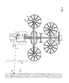
- the adjustment 17 adjusts the scanning range 15 of the laser measuring device 13 different.
- the laser beam 14 could be directed to the feed carpet edge 23, which separates the area of the field still occupied by the crop from the area of the field in which the feed has already been disposed of.
- the setting device 17 provides a presetting for the scanning area 15, which lies in a field area outside the working width or lane of the rake 5, in particular such that a swath 24, which was stored in a previous, adjacent tram, is scanned.
- the scanning of the swath 24 deposited there is significantly easier to evaluate than a possibly only slight transition of a thin feed carpet to a Lovegroundenen grassy area.
- the setting device 17 knows on the one hand, how large the working width of the rake 5 and on the other hand, in which area the swath 24 is stored. In other words, the adjusting device 17 knows how far the swath 24 to be detected is approximately transversely spaced from the lane of the tractor and thus the laser measuring device 13 when approximately approaching connection, so that the scanning region 15 can be set accordingly.
- the scanning region 15 can be adjusted in this case in the direction of travel at the level of the tractor 1, but if necessary, also be arranged a bit far ahead to have enough reaction time for the controller.
- a tractor 1 associated with the power steering device 20 From the detected windrow 24 and its location relative to the tractor 1 and the known data on the geometry of the attachment 3, a tractor 1 associated with the power steering device 20 generate a steering signal to guide the tractor 1 at a predetermined distance at the detected windrow 24 and thereby to process the still unprocessed field area exactly under approximately full utilization of the working width of the rake 5.
- a differently positioned scanning 15 of the laser measuring device 13 can be preset, for which in turn from a data memory 19 associated with the tedder 19 corresponding identification data or preset data are read out by the detection device 16.
- the setting device 17 automatically adjusts the scanning region 15 of the laser beam 14 to an obliquely forward and laterally adjacent to the tractor 1 outside of its lane ground area as a scanning area, in particular such that the transition region of already turned crop to a not yet scanned crop area is scanned.
- the already processed Erntegutteichich characterized by the loosening compared to the still unprocessed Erntegutteppich usually characterized in that the height of the surface of the crop carpet is greater than the height of the still unprocessed surface.
- this height difference can be detected by the laser measuring device 13.
- the position determined therefrom of the transition edge relative to the tractor 1, in particular the transverse distance of the processing edge can be used together with the read from the data memory 19 working width of the tedder 6 of the power steering device 20 to provide a corresponding steering signal to the tractor 1 parallel to the transition edge 25, so that the tedder 6 is driven by utilizing substantially its full working width on connection.
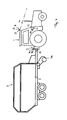
- the laser measuring device 13 when attaching a loading wagon 7 essentially scan a lying in the lane in front of the tractor 1 swath, which is run over by the tractor 1 and is to be picked up by the pickup 26 of the attached wagon 7.
- the scanning width of the scanning region 15 is advantageously adapted to the width of said pickup 26, for example, adjusted to 125% of the working width of the pickup 26.
- the entire swath can be scanned, advantageously the Schwadmitte can be determined from the point of maximum height of the swath and / or from the lateral edges of the sampled swath, their position or their transverse offset relative to the center of the lane of the tractor is determined.
- the power steering device 20 can generate a steering signal to drive the loader wagon 7 exactly over or on the swath to accommodate the latter of the pickup 26 clean.
- At least one other operating parameter of the tractor 1 and / or the loading wagon 7 can be controlled, for example, that larger When the windrow speed is reduced or vice versa with decreasing swath the driving speed is increased, and / or, for example, to the effect that with increasing swath size, the performance and / or speed of the receiving device of the loading wagon 7 is increased.
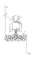
- Fig. 5 shows, when growing a plow lying in front of the tractor 1 bottom portion of the laser measuring device 13 are scanned, the scanning 15 is directed in response to the read identification data or preset data for the plow 8 to an area in front of the tractor 1, the left or is offset right across the lane center. If this is a reversible plow provided as this Fig. 5 1, the said scanning region 15 can be preset once to the right or once to the left depending on the turning position of the plow 8, in particular in such a way that the transitional region between a furrow furrow generated in a preceding lane is scanned to the still unprocessed field section becomes.
- the scanning region 15 can be preset more or less far transversely offset from the lane center of the tractor 1. From the then detected by the laser measuring device 13 position of said transition region between furrows and still unprocessed soil, in particular from the transverse offset of this transition region of the lane center and the geometry data of Plowing the power steering device 20 then generate a corresponding steering signal to guide the plow 8 exactly along said transition edge.
Landscapes
- Life Sciences & Earth Sciences (AREA)
- Engineering & Computer Science (AREA)
- Mechanical Engineering (AREA)
- Soil Sciences (AREA)
- Environmental Sciences (AREA)
- Length Measuring Devices By Optical Means (AREA)
- Guiding Agricultural Machines (AREA)
- Lifting Devices For Agricultural Implements (AREA)
- Soil Working Implements (AREA)
Applications Claiming Priority (1)
| Application Number | Priority Date | Filing Date | Title |
|---|---|---|---|
| DE102011100054A DE102011100054A1 (de) | 2011-04-29 | 2011-04-29 | Landwirtschaftliche Maschine |
Publications (3)
| Publication Number | Publication Date |
|---|---|
| EP2517543A2 true EP2517543A2 (fr) | 2012-10-31 |
| EP2517543A3 EP2517543A3 (fr) | 2012-11-07 |
| EP2517543B1 EP2517543B1 (fr) | 2014-06-11 |
Family
ID=46146504
Family Applications (1)
| Application Number | Title | Priority Date | Filing Date |
|---|---|---|---|
| EP12002876.6A Active EP2517543B1 (fr) | 2011-04-29 | 2012-04-24 | Machine agricole |
Country Status (3)
| Country | Link |
|---|---|
| EP (1) | EP2517543B1 (fr) |
| DE (1) | DE102011100054A1 (fr) |
| ES (1) | ES2496000T3 (fr) |
Cited By (13)
| Publication number | Priority date | Publication date | Assignee | Title |
|---|---|---|---|---|
| WO2015065174A1 (fr) | 2013-10-29 | 2015-05-07 | Forage Innovations B.V. | Engin agricole prévu pour la conduite en courbe |
| US20170118915A1 (en) * | 2015-11-03 | 2017-05-04 | Claas Selbstfahrende Erntemaschinen Gmbh | Surroundings detection device for agricultural work machines |
| BE1024929B1 (nl) * | 2017-05-09 | 2018-08-13 | Cnh Industrial Belgium Nv | Verbeteringen in of met betrekking tot voertuig/aanhangwagen-combinaties |
| BE1024928B1 (nl) * | 2017-05-09 | 2018-08-13 | Cnh Industrial Belgium Nv | Verbeteringen in of met betrekking tot tractor/balenpers- combinaties |
| EP3381252A1 (fr) * | 2017-03-28 | 2018-10-03 | AGCO Feucht GmbH | Système d'assistance de direction pour une combinaison tracteur-outil agricole |
| EP3461313A1 (fr) * | 2017-09-28 | 2019-04-03 | CLAAS E-Systems KGaA mbH & Co KG | Engin agricole |
| US10431016B2 (en) | 2017-01-23 | 2019-10-01 | Deere & Company | Method and device for identification of an implement |
| WO2020037003A1 (fr) | 2018-08-13 | 2020-02-20 | Raven Industries, Inc. | Système de contrôle et de guidage vis-à-vis d'obstacles agricoles comparatif et procédé pour celui-ci |
| EP3818799A1 (fr) * | 2019-11-08 | 2021-05-12 | CLAAS E-Systems GmbH | Machine de travail agricole |
| EP3909417A1 (fr) * | 2020-05-15 | 2021-11-17 | CNH Industrial Belgium N.V. | Système de ratissage agricole et procédé de réglages automatiques |
| EP3912455A1 (fr) * | 2020-05-18 | 2021-11-24 | CLAAS Saulgau GmbH | Appareil de commande de dispositif de fusion et dispositif de fusion |
| US11659785B2 (en) | 2019-10-23 | 2023-05-30 | Cnh Industrial America Llc | Method and system for controlling the height of an agricultural implement relative to the ground |
| US12366860B2 (en) | 2020-12-11 | 2025-07-22 | Raven Industries, Inc. | Sensor fusion in agricultural vehicle steering |
Families Citing this family (4)
| Publication number | Priority date | Publication date | Assignee | Title |
|---|---|---|---|---|
| US20180116121A1 (en) * | 2016-10-28 | 2018-05-03 | Deere & Company | Methods and systems for more efficient hay creation |
| US20180116124A1 (en) * | 2016-10-28 | 2018-05-03 | Deere & Company | Methods and systems for more efficient hay creation |
| US12120972B2 (en) | 2021-09-28 | 2024-10-22 | Deere & Company | Agricultural machine control using work quality based on in situ operation sensing |
| US12114601B2 (en) * | 2021-09-28 | 2024-10-15 | Deere & Company | Agricultural machine speed control based on work quality metrics |
Citations (4)
| Publication number | Priority date | Publication date | Assignee | Title |
|---|---|---|---|---|
| DE19859875A1 (de) | 1998-12-23 | 2000-06-29 | Claas Saulgau Gmbh | Steuerung für landwirtschaftliche Arbeitsmaschine |
| EP1356729B1 (fr) | 2002-04-02 | 2005-11-09 | CLAAS Selbstfahrende Erntemaschinen GmbH | Dispositif de mesure pour machine agricole |
| EP1813142B1 (fr) | 2006-01-31 | 2009-07-08 | Alois Pöttinger Maschinenfabrik GmbH | Machine agricole |
| EP0887660B1 (fr) | 1997-06-25 | 2010-06-09 | CLAAS Selbstfahrende Erntemaschinen GmbH | Dispositif pour montage sur engins agricoles pour le balayage sans contact de contours sur la surface de la terre et un method qu'y correspond |
Family Cites Families (4)
| Publication number | Priority date | Publication date | Assignee | Title |
|---|---|---|---|---|
| DE10129136A1 (de) * | 2001-06-16 | 2002-12-19 | Deere & Co | Einrichtung zur selbsttätigen Lenkung eines landwirtschaftlichen Arbeitsfahrzeugs |
| DE10204702A1 (de) * | 2002-02-05 | 2003-08-14 | Claas Selbstfahr Erntemasch | Ortungssystem an selbstfahrenden landwirtschaftlichen Arbeitsmaschinen |
| DE10208012A1 (de) * | 2002-02-26 | 2003-09-04 | Claas Selbstfahr Erntemasch | Spurführungssystem an einer landwirtschaftlichen Arbeitsmaschine |
| EP2057875A1 (fr) * | 2007-11-08 | 2009-05-13 | Leibniz-Institut für Agrartechnik Potsdam-Bornim e.V. (ATB) | Procédé et agencement destinés à l'établissement de la constitution de plantes sur des machines agricoles |
-
2011
- 2011-04-29 DE DE102011100054A patent/DE102011100054A1/de not_active Withdrawn
-
2012
- 2012-04-24 EP EP12002876.6A patent/EP2517543B1/fr active Active
- 2012-04-24 ES ES12002876.6T patent/ES2496000T3/es active Active
Patent Citations (4)
| Publication number | Priority date | Publication date | Assignee | Title |
|---|---|---|---|---|
| EP0887660B1 (fr) | 1997-06-25 | 2010-06-09 | CLAAS Selbstfahrende Erntemaschinen GmbH | Dispositif pour montage sur engins agricoles pour le balayage sans contact de contours sur la surface de la terre et un method qu'y correspond |
| DE19859875A1 (de) | 1998-12-23 | 2000-06-29 | Claas Saulgau Gmbh | Steuerung für landwirtschaftliche Arbeitsmaschine |
| EP1356729B1 (fr) | 2002-04-02 | 2005-11-09 | CLAAS Selbstfahrende Erntemaschinen GmbH | Dispositif de mesure pour machine agricole |
| EP1813142B1 (fr) | 2006-01-31 | 2009-07-08 | Alois Pöttinger Maschinenfabrik GmbH | Machine agricole |
Cited By (34)
| Publication number | Priority date | Publication date | Assignee | Title |
|---|---|---|---|---|
| WO2015065174A1 (fr) | 2013-10-29 | 2015-05-07 | Forage Innovations B.V. | Engin agricole prévu pour la conduite en courbe |
| US20170118915A1 (en) * | 2015-11-03 | 2017-05-04 | Claas Selbstfahrende Erntemaschinen Gmbh | Surroundings detection device for agricultural work machines |
| EP3165062A1 (fr) * | 2015-11-03 | 2017-05-10 | CLAAS Selbstfahrende Erntemaschinen GmbH | Dispositif de détection d'environnement pour machine de travail agricole |
| US20220000025A1 (en) * | 2015-11-03 | 2022-01-06 | Claas Selbstfahrende Erntemaschinen Gmbh | Surroundings detection device for agricultural work machines |
| US11122740B2 (en) | 2015-11-03 | 2021-09-21 | CLAAS Scibstfahrende Erntemaschinen GmbH | Surroundings detection device for agricultural work machines |
| US11716930B2 (en) * | 2015-11-03 | 2023-08-08 | Claas Selbstfahrende Erntemaschinen Gmbh | Surroundings detection device for agricultural work machines |
| RU2731733C2 (ru) * | 2015-11-03 | 2020-09-08 | КЛААС Зельбстфаренде Эрнтемашинен ГмбХ | Сельскохозяйственная рабочая машина с устройством детектирования окружающего пространства |
| US10431016B2 (en) | 2017-01-23 | 2019-10-01 | Deere & Company | Method and device for identification of an implement |
| EP3381252A1 (fr) * | 2017-03-28 | 2018-10-03 | AGCO Feucht GmbH | Système d'assistance de direction pour une combinaison tracteur-outil agricole |
| CN110612021A (zh) * | 2017-05-09 | 2019-12-24 | 凯斯纽荷兰(中国)管理有限公司 | 车辆-拖车组合体中的改进或与车辆-拖车组合体有关的改进 |
| US11185004B2 (en) | 2017-05-09 | 2021-11-30 | Cnh Industrial America Llc | Vehicle-trailer combinations |
| CN110740632A (zh) * | 2017-05-09 | 2020-01-31 | 凯斯纽荷兰(中国)管理有限公司 | 拖拉机-打捆机组合中的改进或与之有关的改进 |
| US11812680B2 (en) | 2017-05-09 | 2023-11-14 | Cnh Industrial America Llc | Tractor-baler combinations |
| WO2018206678A1 (fr) * | 2017-05-09 | 2018-11-15 | Cnh Industrial Belgium Nv | Perfectionnements apportés ou liés à des combinés tracteur-ramasseuse-presse |
| RU2738423C1 (ru) * | 2017-05-09 | 2020-12-14 | СиЭнЭйч ИНДАСТРИАЛ БЕЛДЖИУМ НВ | Комбинация подвижного транспортного средства и прицепа и способ управления комбинации транспортного средства и прицепа |
| AU2018265089B2 (en) * | 2017-05-09 | 2021-03-04 | Cnh Industrial Belgium Nv | Improvements in or relating to tractor-baler combinations |
| AU2018265094B2 (en) * | 2017-05-09 | 2021-04-08 | Cnh Industrial Belgium Nv | Improvements in or relating to vehicle-trailer combinations |
| WO2018206683A1 (fr) * | 2017-05-09 | 2018-11-15 | Cnh Industrial Belgium Nv | Améliorations sur, ou liées à, des associations remorques-véhicules |
| BE1024928B1 (nl) * | 2017-05-09 | 2018-08-13 | Cnh Industrial Belgium Nv | Verbeteringen in of met betrekking tot tractor/balenpers- combinaties |
| EP3634103B1 (fr) | 2017-05-09 | 2022-10-19 | CNH Industrial Belgium NV | Améliorations sur, ou liées à, des associations remorques-véhicules |
| BE1024929B1 (nl) * | 2017-05-09 | 2018-08-13 | Cnh Industrial Belgium Nv | Verbeteringen in of met betrekking tot voertuig/aanhangwagen-combinaties |
| EP3461313A1 (fr) * | 2017-09-28 | 2019-04-03 | CLAAS E-Systems KGaA mbH & Co KG | Engin agricole |
| RU2769473C2 (ru) * | 2017-09-28 | 2022-04-01 | КЛААС Е-Системс ГмбХ | Сельскохозяйственная рабочая машина |
| EP3836771A4 (fr) * | 2018-08-13 | 2022-06-01 | Raven Industries, Inc. | Système de contrôle et de guidage vis-à-vis d'obstacles agricoles comparatif et procédé pour celui-ci |
| US11470760B2 (en) | 2018-08-13 | 2022-10-18 | Raven Industries, Inc. | Comparative agricultural obstacle monitor and guidance system and method for same |
| US11687083B2 (en) | 2018-08-13 | 2023-06-27 | Raven Industries, Inc. | Comparative agricultural obstacle monitor and guidance system and method for same |
| WO2020037003A1 (fr) | 2018-08-13 | 2020-02-20 | Raven Industries, Inc. | Système de contrôle et de guidage vis-à-vis d'obstacles agricoles comparatif et procédé pour celui-ci |
| US11659785B2 (en) | 2019-10-23 | 2023-05-30 | Cnh Industrial America Llc | Method and system for controlling the height of an agricultural implement relative to the ground |
| EP3818799A1 (fr) * | 2019-11-08 | 2021-05-12 | CLAAS E-Systems GmbH | Machine de travail agricole |
| EP3909417A1 (fr) * | 2020-05-15 | 2021-11-17 | CNH Industrial Belgium N.V. | Système de ratissage agricole et procédé de réglages automatiques |
| US12336455B2 (en) | 2020-05-15 | 2025-06-24 | Cnh Industrial America Llc | Agricultural raking system and method for automatic settings |
| EP3912455A1 (fr) * | 2020-05-18 | 2021-11-24 | CLAAS Saulgau GmbH | Appareil de commande de dispositif de fusion et dispositif de fusion |
| US12058961B2 (en) | 2020-05-18 | 2024-08-13 | Claas Saulgau Gmbh | Merger control device for adjusting conveyor speed or pickup speed as a function of steering angle |
| US12366860B2 (en) | 2020-12-11 | 2025-07-22 | Raven Industries, Inc. | Sensor fusion in agricultural vehicle steering |
Also Published As
| Publication number | Publication date |
|---|---|
| EP2517543A3 (fr) | 2012-11-07 |
| EP2517543B1 (fr) | 2014-06-11 |
| ES2496000T3 (es) | 2014-09-18 |
| DE102011100054A1 (de) | 2012-10-31 |
Similar Documents
| Publication | Publication Date | Title |
|---|---|---|
| EP2517543B1 (fr) | Machine agricole | |
| EP1630574B1 (fr) | Dispositif monté sur des machines agricoles destiné au balayage sans contact de contours sýétendant sur le sol | |
| EP3300579B1 (fr) | Machine agricole automotrice | |
| EP1529428B1 (fr) | Procédé et système pour la direction automatique d'une machine agricole | |
| EP0812530B1 (fr) | Moissonneuse à tablier à hauteur réglable | |
| EP2545761B1 (fr) | Procédé de fonctionnement d'une moissonneuse automobile | |
| EP2272312B1 (fr) | Appareil agricole | |
| BE1024928B1 (nl) | Verbeteringen in of met betrekking tot tractor/balenpers- combinaties | |
| EP1266554B1 (fr) | Dispositif de direction automatique pour véhicule de travail agricole | |
| EP1208738B1 (fr) | Dispositif de positionnement pour un ramasseur agricole | |
| EP3300561B1 (fr) | Machine agricole automotrice | |
| EP1932416B1 (fr) | Dispositif muni d'une première et d'une seconde unité de travail | |
| EP1219159A1 (fr) | Procédé et dispositif de commande automatique d'un appareil de transfert de machines agricoles de récolte | |
| DE102005005557B4 (de) | Vorrichtung zur Steuerung und/oder Regelung einer Landmaschine mittels einer Bilderfassungs- und -verarbeitungseinrichtung | |
| DE102008002006A1 (de) | Steueranordnung zur Kontrolle des Überladens landwirtschaftlichen Ernteguts von einer Erntemaschine auf ein Transportfahrzeug | |
| EP1813142B1 (fr) | Machine agricole | |
| EP3461313A1 (fr) | Engin agricole | |
| EP2520155A1 (fr) | Moissonneuse avec au moins un convoyeur transversal | |
| DE4318798A1 (de) | Automatisch selbstfahrende Arbeitsmaschine zur Bearbeitung von definierten Flächen | |
| EP4052550A1 (fr) | Dispositif de compensation de la suspension latérale pour la viticulture | |
| EP1862049A1 (fr) | Machine agricole | |
| DE202006019070U1 (de) | Vorrichtung mit einer ersten und einer zweiten Arbeitseinheit | |
| DE102023124836A1 (de) | Verfahren zur Ansteuerung mindestens einer selbstfahrenden landwirtschaftlichen Arbeitsmaschine | |
| DE102022125094A1 (de) | Landwirtschaftliche Erntemaschine | |
| EP3400778A1 (fr) | Procédé de fonctionnement d'une moissonneuse autonome |
Legal Events
| Date | Code | Title | Description |
|---|---|---|---|
| PUAL | Search report despatched |
Free format text: ORIGINAL CODE: 0009013 |
|
| PUAI | Public reference made under article 153(3) epc to a published international application that has entered the european phase |
Free format text: ORIGINAL CODE: 0009012 |
|
| AK | Designated contracting states |
Kind code of ref document: A2 Designated state(s): AL AT BE BG CH CY CZ DE DK EE ES FI FR GB GR HR HU IE IS IT LI LT LU LV MC MK MT NL NO PL PT RO RS SE SI SK SM TR |
|
| AX | Request for extension of the european patent |
Extension state: BA ME |
|
| AK | Designated contracting states |
Kind code of ref document: A3 Designated state(s): AL AT BE BG CH CY CZ DE DK EE ES FI FR GB GR HR HU IE IS IT LI LT LU LV MC MK MT NL NO PL PT RO RS SE SI SK SM TR |
|
| AX | Request for extension of the european patent |
Extension state: BA ME |
|
| RIC1 | Information provided on ipc code assigned before grant |
Ipc: A01B 69/00 20060101AFI20121003BHEP |
|
| 17P | Request for examination filed |
Effective date: 20130507 |
|
| REG | Reference to a national code |
Ref country code: DE Ref legal event code: R079 Ref document number: 502012000836 Country of ref document: DE Free format text: PREVIOUS MAIN CLASS: A01B0069000000 Ipc: A01B0069040000 |
|
| GRAP | Despatch of communication of intention to grant a patent |
Free format text: ORIGINAL CODE: EPIDOSNIGR1 |
|
| RIC1 | Information provided on ipc code assigned before grant |
Ipc: A01B 69/04 20060101AFI20131030BHEP Ipc: A01B 69/00 20060101ALI20131030BHEP |
|
| INTG | Intention to grant announced |
Effective date: 20131205 |
|
| GRAS | Grant fee paid |
Free format text: ORIGINAL CODE: EPIDOSNIGR3 |
|
| GRAA | (expected) grant |
Free format text: ORIGINAL CODE: 0009210 |
|
| AK | Designated contracting states |
Kind code of ref document: B1 Designated state(s): AL AT BE BG CH CY CZ DE DK EE ES FI FR GB GR HR HU IE IS IT LI LT LU LV MC MK MT NL NO PL PT RO RS SE SI SK SM TR |
|
| REG | Reference to a national code |
Ref country code: GB Ref legal event code: FG4D Free format text: NOT ENGLISH |
|
| REG | Reference to a national code |
Ref country code: CH Ref legal event code: EP Ref country code: CH Ref legal event code: NV Representative=s name: KELLER AND PARTNER PATENTANWAELTE AG, CH |
|
| REG | Reference to a national code |
Ref country code: IE Ref legal event code: FG4D Free format text: LANGUAGE OF EP DOCUMENT: GERMAN |
|
| REG | Reference to a national code |
Ref country code: AT Ref legal event code: REF Ref document number: 671730 Country of ref document: AT Kind code of ref document: T Effective date: 20140715 |
|
| REG | Reference to a national code |
Ref country code: DE Ref legal event code: R096 Ref document number: 502012000836 Country of ref document: DE Effective date: 20140724 |
|
| REG | Reference to a national code |
Ref country code: SE Ref legal event code: TRGR |
|
| REG | Reference to a national code |
Ref country code: ES Ref legal event code: FG2A Ref document number: 2496000 Country of ref document: ES Kind code of ref document: T3 Effective date: 20140918 |
|
| REG | Reference to a national code |
Ref country code: NL Ref legal event code: T3 |
|
| PG25 | Lapsed in a contracting state [announced via postgrant information from national office to epo] |
Ref country code: FI Free format text: LAPSE BECAUSE OF FAILURE TO SUBMIT A TRANSLATION OF THE DESCRIPTION OR TO PAY THE FEE WITHIN THE PRESCRIBED TIME-LIMIT Effective date: 20140611 Ref country code: LT Free format text: LAPSE BECAUSE OF FAILURE TO SUBMIT A TRANSLATION OF THE DESCRIPTION OR TO PAY THE FEE WITHIN THE PRESCRIBED TIME-LIMIT Effective date: 20140611 Ref country code: GR Free format text: LAPSE BECAUSE OF FAILURE TO SUBMIT A TRANSLATION OF THE DESCRIPTION OR TO PAY THE FEE WITHIN THE PRESCRIBED TIME-LIMIT Effective date: 20140912 Ref country code: NO Free format text: LAPSE BECAUSE OF FAILURE TO SUBMIT A TRANSLATION OF THE DESCRIPTION OR TO PAY THE FEE WITHIN THE PRESCRIBED TIME-LIMIT Effective date: 20140911 |
|
| REG | Reference to a national code |
Ref country code: LT Ref legal event code: MG4D |
|
| PG25 | Lapsed in a contracting state [announced via postgrant information from national office to epo] |
Ref country code: RS Free format text: LAPSE BECAUSE OF FAILURE TO SUBMIT A TRANSLATION OF THE DESCRIPTION OR TO PAY THE FEE WITHIN THE PRESCRIBED TIME-LIMIT Effective date: 20140611 Ref country code: HR Free format text: LAPSE BECAUSE OF FAILURE TO SUBMIT A TRANSLATION OF THE DESCRIPTION OR TO PAY THE FEE WITHIN THE PRESCRIBED TIME-LIMIT Effective date: 20140611 Ref country code: LV Free format text: LAPSE BECAUSE OF FAILURE TO SUBMIT A TRANSLATION OF THE DESCRIPTION OR TO PAY THE FEE WITHIN THE PRESCRIBED TIME-LIMIT Effective date: 20140611 |
|
| PG25 | Lapsed in a contracting state [announced via postgrant information from national office to epo] |
Ref country code: RO Free format text: LAPSE BECAUSE OF FAILURE TO SUBMIT A TRANSLATION OF THE DESCRIPTION OR TO PAY THE FEE WITHIN THE PRESCRIBED TIME-LIMIT Effective date: 20140611 Ref country code: SK Free format text: LAPSE BECAUSE OF FAILURE TO SUBMIT A TRANSLATION OF THE DESCRIPTION OR TO PAY THE FEE WITHIN THE PRESCRIBED TIME-LIMIT Effective date: 20140611 Ref country code: PT Free format text: LAPSE BECAUSE OF FAILURE TO SUBMIT A TRANSLATION OF THE DESCRIPTION OR TO PAY THE FEE WITHIN THE PRESCRIBED TIME-LIMIT Effective date: 20141013 Ref country code: EE Free format text: LAPSE BECAUSE OF FAILURE TO SUBMIT A TRANSLATION OF THE DESCRIPTION OR TO PAY THE FEE WITHIN THE PRESCRIBED TIME-LIMIT Effective date: 20140611 |
|
| PG25 | Lapsed in a contracting state [announced via postgrant information from national office to epo] |
Ref country code: PL Free format text: LAPSE BECAUSE OF FAILURE TO SUBMIT A TRANSLATION OF THE DESCRIPTION OR TO PAY THE FEE WITHIN THE PRESCRIBED TIME-LIMIT Effective date: 20140611 Ref country code: IS Free format text: LAPSE BECAUSE OF FAILURE TO SUBMIT A TRANSLATION OF THE DESCRIPTION OR TO PAY THE FEE WITHIN THE PRESCRIBED TIME-LIMIT Effective date: 20141011 |
|
| REG | Reference to a national code |
Ref country code: DE Ref legal event code: R097 Ref document number: 502012000836 Country of ref document: DE |
|
| REG | Reference to a national code |
Ref country code: CH Ref legal event code: PCAR Free format text: NEW ADDRESS: EIGERSTRASSE 2 POSTFACH, 3000 BERN 14 (CH) |
|
| PLBE | No opposition filed within time limit |
Free format text: ORIGINAL CODE: 0009261 |
|
| STAA | Information on the status of an ep patent application or granted ep patent |
Free format text: STATUS: NO OPPOSITION FILED WITHIN TIME LIMIT |
|
| PG25 | Lapsed in a contracting state [announced via postgrant information from national office to epo] |
Ref country code: DK Free format text: LAPSE BECAUSE OF FAILURE TO SUBMIT A TRANSLATION OF THE DESCRIPTION OR TO PAY THE FEE WITHIN THE PRESCRIBED TIME-LIMIT Effective date: 20140611 |
|
| 26N | No opposition filed |
Effective date: 20150312 |
|
| REG | Reference to a national code |
Ref country code: DE Ref legal event code: R097 Ref document number: 502012000836 Country of ref document: DE Effective date: 20150312 |
|
| PG25 | Lapsed in a contracting state [announced via postgrant information from national office to epo] |
Ref country code: SI Free format text: LAPSE BECAUSE OF FAILURE TO SUBMIT A TRANSLATION OF THE DESCRIPTION OR TO PAY THE FEE WITHIN THE PRESCRIBED TIME-LIMIT Effective date: 20140611 |
|
| REG | Reference to a national code |
Ref country code: DE Ref legal event code: R119 Ref document number: 502012000836 Country of ref document: DE |
|
| PG25 | Lapsed in a contracting state [announced via postgrant information from national office to epo] |
Ref country code: LU Free format text: LAPSE BECAUSE OF FAILURE TO SUBMIT A TRANSLATION OF THE DESCRIPTION OR TO PAY THE FEE WITHIN THE PRESCRIBED TIME-LIMIT Effective date: 20150424 Ref country code: MC Free format text: LAPSE BECAUSE OF FAILURE TO SUBMIT A TRANSLATION OF THE DESCRIPTION OR TO PAY THE FEE WITHIN THE PRESCRIBED TIME-LIMIT Effective date: 20140611 |
|
| PG25 | Lapsed in a contracting state [announced via postgrant information from national office to epo] |
Ref country code: DE Free format text: LAPSE BECAUSE OF NON-PAYMENT OF DUE FEES Effective date: 20151103 |
|
| REG | Reference to a national code |
Ref country code: FR Ref legal event code: PLFP Year of fee payment: 5 |
|
| PGFP | Annual fee paid to national office [announced via postgrant information from national office to epo] |
Ref country code: GB Payment date: 20160425 Year of fee payment: 5 Ref country code: ES Payment date: 20160422 Year of fee payment: 5 |
|
| PGFP | Annual fee paid to national office [announced via postgrant information from national office to epo] |
Ref country code: IT Payment date: 20160429 Year of fee payment: 5 |
|
| PG25 | Lapsed in a contracting state [announced via postgrant information from national office to epo] |
Ref country code: MT Free format text: LAPSE BECAUSE OF FAILURE TO SUBMIT A TRANSLATION OF THE DESCRIPTION OR TO PAY THE FEE WITHIN THE PRESCRIBED TIME-LIMIT Effective date: 20140611 |
|
| REG | Reference to a national code |
Ref country code: FR Ref legal event code: PLFP Year of fee payment: 6 |
|
| PG25 | Lapsed in a contracting state [announced via postgrant information from national office to epo] |
Ref country code: BG Free format text: LAPSE BECAUSE OF FAILURE TO SUBMIT A TRANSLATION OF THE DESCRIPTION OR TO PAY THE FEE WITHIN THE PRESCRIBED TIME-LIMIT Effective date: 20140611 Ref country code: SM Free format text: LAPSE BECAUSE OF FAILURE TO SUBMIT A TRANSLATION OF THE DESCRIPTION OR TO PAY THE FEE WITHIN THE PRESCRIBED TIME-LIMIT Effective date: 20140611 Ref country code: HU Free format text: LAPSE BECAUSE OF FAILURE TO SUBMIT A TRANSLATION OF THE DESCRIPTION OR TO PAY THE FEE WITHIN THE PRESCRIBED TIME-LIMIT; INVALID AB INITIO Effective date: 20120424 |
|
| PG25 | Lapsed in a contracting state [announced via postgrant information from national office to epo] |
Ref country code: CY Free format text: LAPSE BECAUSE OF FAILURE TO SUBMIT A TRANSLATION OF THE DESCRIPTION OR TO PAY THE FEE WITHIN THE PRESCRIBED TIME-LIMIT Effective date: 20140611 |
|
| PG25 | Lapsed in a contracting state [announced via postgrant information from national office to epo] |
Ref country code: BE Free format text: LAPSE BECAUSE OF NON-PAYMENT OF DUE FEES Effective date: 20150430 |
|
| PG25 | Lapsed in a contracting state [announced via postgrant information from national office to epo] |
Ref country code: TR Free format text: LAPSE BECAUSE OF FAILURE TO SUBMIT A TRANSLATION OF THE DESCRIPTION OR TO PAY THE FEE WITHIN THE PRESCRIBED TIME-LIMIT Effective date: 20140611 |
|
| GBPC | Gb: european patent ceased through non-payment of renewal fee |
Effective date: 20170424 |
|
| PG25 | Lapsed in a contracting state [announced via postgrant information from national office to epo] |
Ref country code: GB Free format text: LAPSE BECAUSE OF NON-PAYMENT OF DUE FEES Effective date: 20170424 |
|
| REG | Reference to a national code |
Ref country code: FR Ref legal event code: PLFP Year of fee payment: 7 |
|
| PG25 | Lapsed in a contracting state [announced via postgrant information from national office to epo] |
Ref country code: IT Free format text: LAPSE BECAUSE OF NON-PAYMENT OF DUE FEES Effective date: 20170424 |
|
| PG25 | Lapsed in a contracting state [announced via postgrant information from national office to epo] |
Ref country code: MK Free format text: LAPSE BECAUSE OF FAILURE TO SUBMIT A TRANSLATION OF THE DESCRIPTION OR TO PAY THE FEE WITHIN THE PRESCRIBED TIME-LIMIT Effective date: 20140611 |
|
| REG | Reference to a national code |
Ref country code: ES Ref legal event code: FD2A Effective date: 20180629 |
|
| PG25 | Lapsed in a contracting state [announced via postgrant information from national office to epo] |
Ref country code: ES Free format text: LAPSE BECAUSE OF NON-PAYMENT OF DUE FEES Effective date: 20170425 |
|
| PGFP | Annual fee paid to national office [announced via postgrant information from national office to epo] |
Ref country code: CH Payment date: 20180416 Year of fee payment: 7 |
|
| PG25 | Lapsed in a contracting state [announced via postgrant information from national office to epo] |
Ref country code: AL Free format text: LAPSE BECAUSE OF FAILURE TO SUBMIT A TRANSLATION OF THE DESCRIPTION OR TO PAY THE FEE WITHIN THE PRESCRIBED TIME-LIMIT Effective date: 20140611 |
|
| PGFP | Annual fee paid to national office [announced via postgrant information from national office to epo] |
Ref country code: AT Payment date: 20190313 Year of fee payment: 8 |
|
| REG | Reference to a national code |
Ref country code: CH Ref legal event code: PL |
|
| PG25 | Lapsed in a contracting state [announced via postgrant information from national office to epo] |
Ref country code: CH Free format text: LAPSE BECAUSE OF NON-PAYMENT OF DUE FEES Effective date: 20190430 Ref country code: LI Free format text: LAPSE BECAUSE OF NON-PAYMENT OF DUE FEES Effective date: 20190430 |
|
| REG | Reference to a national code |
Ref country code: AT Ref legal event code: MM01 Ref document number: 671730 Country of ref document: AT Kind code of ref document: T Effective date: 20200424 |
|
| PG25 | Lapsed in a contracting state [announced via postgrant information from national office to epo] |
Ref country code: AT Free format text: LAPSE BECAUSE OF NON-PAYMENT OF DUE FEES Effective date: 20200424 |
|
| PGFP | Annual fee paid to national office [announced via postgrant information from national office to epo] |
Ref country code: SE Payment date: 20220325 Year of fee payment: 11 Ref country code: CZ Payment date: 20220315 Year of fee payment: 11 |
|
| P01 | Opt-out of the competence of the unified patent court (upc) registered |
Effective date: 20230613 |
|
| REG | Reference to a national code |
Ref country code: SE Ref legal event code: EUG |
|
| PG25 | Lapsed in a contracting state [announced via postgrant information from national office to epo] |
Ref country code: SE Free format text: LAPSE BECAUSE OF NON-PAYMENT OF DUE FEES Effective date: 20230425 Ref country code: CZ Free format text: LAPSE BECAUSE OF NON-PAYMENT OF DUE FEES Effective date: 20230424 |
|
| PGFP | Annual fee paid to national office [announced via postgrant information from national office to epo] |
Ref country code: NL Payment date: 20250423 Year of fee payment: 14 |
|
| PGFP | Annual fee paid to national office [announced via postgrant information from national office to epo] |
Ref country code: FR Payment date: 20250425 Year of fee payment: 14 |
|
| PGFP | Annual fee paid to national office [announced via postgrant information from national office to epo] |
Ref country code: IE Payment date: 20250425 Year of fee payment: 14 |