EP2517543A2 - Agricultural machine - Google Patents
Agricultural machine Download PDFInfo
- Publication number
- EP2517543A2 EP2517543A2 EP12002876A EP12002876A EP2517543A2 EP 2517543 A2 EP2517543 A2 EP 2517543A2 EP 12002876 A EP12002876 A EP 12002876A EP 12002876 A EP12002876 A EP 12002876A EP 2517543 A2 EP2517543 A2 EP 2517543A2
- Authority
- EP
- European Patent Office
- Prior art keywords
- attachment
- scanning
- detected
- laser measuring
- agricultural machine
- Prior art date
- Legal status (The legal status is an assumption and is not a legal conclusion. Google has not performed a legal analysis and makes no representation as to the accuracy of the status listed.)
- Granted
Links
Images

Classifications
-
- A—HUMAN NECESSITIES
- A01—AGRICULTURE; FORESTRY; ANIMAL HUSBANDRY; HUNTING; TRAPPING; FISHING
- A01B—SOIL WORKING IN AGRICULTURE OR FORESTRY; PARTS, DETAILS, OR ACCESSORIES OF AGRICULTURAL MACHINES OR IMPLEMENTS, IN GENERAL
- A01B69/00—Steering of agricultural machines or implements; Guiding agricultural machines or implements on a desired track
- A01B69/007—Steering or guiding of agricultural vehicles, e.g. steering of the tractor to keep the plough in the furrow
- A01B69/008—Steering or guiding of agricultural vehicles, e.g. steering of the tractor to keep the plough in the furrow automatic
-
- A—HUMAN NECESSITIES
- A01—AGRICULTURE; FORESTRY; ANIMAL HUSBANDRY; HUNTING; TRAPPING; FISHING
- A01B—SOIL WORKING IN AGRICULTURE OR FORESTRY; PARTS, DETAILS, OR ACCESSORIES OF AGRICULTURAL MACHINES OR IMPLEMENTS, IN GENERAL
- A01B69/00—Steering of agricultural machines or implements; Guiding agricultural machines or implements on a desired track
- A01B69/001—Steering by means of optical assistance, e.g. television cameras
Definitions
- the present invention relates to an agricultural machine with an attachment for growing various implements for Erntegut- and / or soil cultivation, a ground detection device for contactless detection of a soil and / or Erntegutkontur, and a control device for controlling the agricultural machine and / or the attachment in dependence the detected soil and / or Erntegutkontur, wherein the soil detection device comprises at least one laser measuring device, the laser beam for scanning the soil and / or Erntegutkontur is feasible over a scanning range.
- the DE 198 59 875 A1 a haymaking machine, on which a capacitive or after the Doppler effect sensor is provided by means of which not directly the soil surface itself, but a lying Erntegutschwad to be detected in order to raise the working organs of the haymaking machine, if said sensor Randschwad which is not to be processed by the working bodies.
- the EP 18 13 142 B1 further proposes an agricultural machine, in which an acoustic scanning sensor emits scanning signals in different frequencies, in order to detect the contour of the ground itself on the one hand and the contour of a Erntegutschwads lying on the other. In this way, on the one hand, the height adjustment of the pickup in dependence on the detected ground contour and on the other hand, the drive power of the pickup can be varied depending on the detected swath volume.
- the laser signal is in this case reflected at a respective contour point, whereby the distance of the contour point can be determined by means of a transit time measurement, from which in conjunction with the known geometry data of the inclination angle of the laser beam to the horizontal, the deflection angle of the laser beam with respect to a vertical plane extending in the direction of travel and the Mounting height of the laser measuring device, the exact position of the respective contour point can be determined.
- the soil or Erntegutkontur to be recorded for the respective agricultural task can be arranged in different areas.
- the cutting edge to be observed during mowing is usually clearly offset to the side next to the tractor, while the Erntegutschwad to be detected for a baler or a loading wagon is usually centrally located in the lane of the tractor.
- the scanning range of the laser measuring device is adjusted to be sufficiently wide in order to be able to record these differently positioned soil or crop contours for different tasks, very large amounts of data accumulate, which have to be processed by the evaluation device.
- the detection speed suffers, so that at higher speeds no sufficiently fast intervention in the steering of the tractor or the control of the operating parameters of the implement can be guaranteed.
- the scanning range is set further forward, ie with a greater front distance, a very flat scanning angle with respect to the horizontal results at a limited mounting height of the laser measuring device, as a result of which the scanned contours are greatly distorted, similar to an oblique cut.
- the present invention is therefore based on the object to provide an improved agricultural machine of the type mentioned, which avoids the disadvantages of the prior art and further develops the latter in an advantageous manner.
- an improved soil or crop contour scanning by means of a laser beam is to be achieved, which has a sufficiently large scanning area in order to be able to precisely record differently shaped and positioned soil or crop contours for different implements, without causing excessive amounts of data.
- a detection device is provided for detecting the attachment attached to the attachment device, wherein the scanning range of the laser measuring device is set by an adjustment device as a function of the respectively detected attachment.
- the laser measuring device is associated with an intelligent control system, which knows for different attachments, where in each case the observed floor contour section and the laser measuring device accordingly controls in terms of their scanning so that the scanning specifically for the respective attachment fits.
- a data bus can be provided, by means of which implement identification data and setting data can be transmitted.
- the detection device for detecting the respectively attached attachment, the adjusting device for adjusting the scanning range of the laser measuring device and the control system communicate with each other via data bus.
- the detection of the respective attachment for presetting the scanning range of the laser measuring device can basically be done in various ways.
- the detection can be carried out without contact, wherein the detection device may have a reading device for attaching attachable to the attachment data memory, for example in the form of a transponder chip, wherein in said data storage attachment identification data and / or setting data for the laser measuring device can be stored.
- the data is transferred from the attached to the attachment data storage device to the reading device, wherein based on the transmitted identification data and / or setting data, the setting the preset range of the laser measuring device accordingly.
- a barcode reader which can read in a barcode attached to the attachment.
- other data storage and transmission means may be provided.
- manual or semi-automatic attachment detection can also be provided, for example such that the setting device for setting the scanning range of the laser measuring device has an input device, for example in the form of a touch screen, a keyboard or a magnetic stripe reader, into which a data card plugged in or on which such a data card must be pulled past.
- Such a manual input option for the implement identification data can also be provided in addition to the above-described automatic detection, for example in order to be able to make a default setting of the laser scanning range in the event of data transmission problems.
- the default setting of the laser beam scanning range can basically be done in various ways. Depending on the design of the laser scanner, it may be advantageous, for example, to have a horizontal and / or vertical angle range, in which the laser measuring device scans the soil or Erntegutteppich to restrict so as to hide unrecognizable areas and thereby significantly reduce the amount of data.
- the restriction of the scanning angle ranges or the blanking of unusable ranges can advantageously be effected by software, for example by blanking or filtering out the scan data provided in a region which is not required. As a result, computing time and bus capacity can be saved.
- a laser measuring device which operates with a scanning angle of 70 ° and can record different tilt angles to the horizontal by means of tiltable mirrors, by way of example only a section of, for example, 35 ° of the mentioned scanning angle range of, for example, 70 ° can be used and of the several horizontal Scanning angles, for example, only one used for the evaluation, while the rest is hidden or filtered out.
- the angle of inclination of the laser beam relative to the horizontal can be varied by the setting device in dependence on the respectively detected attachment such that the scanning range for a driven at a higher driving speed attachment viewed in the direction of travel lying ahead and less for an operated at a lower driving speed attachment is placed far in front. If, for example, a loader wagon is mounted, with which it is possible to drive quite quickly, the laser measuring device is pre-set to look relatively far forward with the laser beam and to scan a swath section lying relatively far in front of the machine.
- the laser measuring device is preset in such a way based on the recorded data of the baler that the scanning is closer to the tractor or less far from the tractor to achieve a higher accuracy of contour scanning with sufficient lead time.
- the scanning range of the laser measuring device can also be preset differently with regard to its scanning width and / or with regard to its position transversely to the traffic lane, depending on which attachment is used. If, for example, a loading wagon is mounted which has a large receiving width at the pickup, the laser measuring device can be preset in such a way that a relatively wide area in the lane in front of the tractor or loader wagon is detected by the laser measuring device. Since a correspondingly wide swath usually lies in the lane of the tractor, the scanning beam of the laser measuring device is reciprocated over a fairly large width, the scanning area being provided substantially in the lane of the tractor.
- the laser measuring device does not necessarily have to be directed to a respective soil or crop contour that is currently being processed.
- the laser measuring device is set so that a not to be machined field section is scanned, in particular one next to the processed Trunk lying field section, which was previously processed in a previous tram. Namely, there are often easier-to-grasp contours, for example, when crop was stored in a swath.
- the size of the transverse offset of Scanning range is set away from the center of the lane of the machine depending on the respectively detected attachment.
- the detected identification data and / or setting data for the respective attachment information about the working width and / or the lateral projection of the respective attachment so that the control for the laser measuring device knows how far with correct connection driving a previously generated crop contour, for example in the form of a swath or a generated bottom contour would have to be arranged laterally spaced, for example in the form of a furrow.
- the width of the scanning range can also be preset accordingly. If, for example, a rake is being cultivated, the laser measuring device can detect the area in which a windrow deposited on the previously traveled lane lies, because the controller knows how far to the side of the windrow must lie from the detected working width of the rake and the known, commonly stored swath position , if correctly driven on connection.
- the scanning is set depending on the respectively detected attachment to a scan width which is less than 150% of the working width of the attachment.
- the scan width can also be set to less than 75% of the working width of the mounted implement. If, for example, a loader wagon is mounted, the scanning width of the laser beam is advantageously set to a range of approximately 100% to 150% of the width of the pickup of the wagon, since it accommodates correspondingly broad crop swaths can be.
- the sampling width can be set much smaller than the working width of the mower because the crop edge is usually sharply demarcated and can vary only in a small area in terms of their location, the only a fraction of the working width of the mower.
- the scan width of the laser beam it may be sufficient to set the scan width of the laser beam to less than 50% of the working width of the attachment machine.
- the setting device for setting the scanning range of the laser measuring device can basically determine the default settings in various ways.
- the scanning ranges can be calculated from the identification data and associated information about the working width of the respective attachment.
- the setting device can also have a data memory or be connectable to such a data memory by means of a data transmission device in order to read from the data memory for a respective attachment associated default data and to use for setting the scanning range.
- a plurality of data sets for the aforementioned preset data of different attachments can advantageously be stored here, so that when a respectively coupled attachment is detected, only the appropriate preset data has to be read from the data memory in order to obtain the scan range of the Set the laser measuring device for the respective implement correctly.
- a power steering device may be provided which provides a steering signal in dependence on the ground or crop contour respectively determined by the laser measuring device and its position relative to the agricultural machine in order to be able to act on the said machine To be able to drive along the soil or crop contour.
- said steering signal may, for example, be a signal displayed on a display, for example in the form of an arrow pointing to the right or left, on the basis of which the tractor operator sees whether he has to steer to the right or left.
- the steering signal may also be a drive signal for an automatically operating steering device which automatically controls the steering angle of the agricultural machine as a function of said steering signal.
- the power steering device advantageously comprises an evaluation device which generates the steering signal as a function of the respectively grasped attachment and its working width as well as the detected position of the ground or crop contour.
- a machining edge can be scanned from an already processed area of the field from an earlier tram and used in the aforementioned manner. For example, when installing a rake a windrow stored in a previous lane, which is when driving the current tram next to the agricultural machine and its working width, detected and used for the steering signal, so that the agricultural machine at a predetermined distance laterally next to said Schwad drives along.
- the loosened crop carpet can be scanned, which has been loosened in a previous lane, in particular, the transition between the already loosened feed carpet area and the not yet loosened feed carpet area can be determined.
- the steering signal can be generated in such a way that the current tramline is placed so that the working width of the tentter overlaps slightly with the already loosened area, on the one hand to use the working width of the tentter as completely as possible, but on the other hand to achieve complete tedding without unprocessed transition areas ,
- variable laser measuring device can also be used in dependence on the detected soil and / or crop contour, its size and / or condition and / or position at least control another machine or attachment operating parameters, such as a rotational speed of a working rotor, a working height of a working unit or the power supply to a drive or the driving speed.
- the evaluation of the data provided by the laser measuring device and the functions and commands derived therefrom can be varied depending on the respectively detected or identified attachment.
- an evaluation unit of the control device can evaluate the data provided by the laser measuring device to determine a swath contour and / or the cross-sectional profile of the scanned crop regions, for example to adapt the performance and picking speed of the pickup truck to the loader depending thereon ,
- the contour of the crop or its cross-sectional profile is less interesting, so that the evaluation of the detection device can be informed that the data evaluation is omitted with respect to the contour profile and instead determined only a Mähkante and / or the grass height becomes.
- the arithmetic operations to be performed and the required data capacities can be significantly reduced.
- the agricultural machine may include a tractor 1, which has a hitch 2 to grow various attachments 3 can.
- the hitch 2 can both rear side and front side each have a mounting unit, for example in the form of a three-point linkage include in order to be able to grow attachments both on the rear and on the front.
- the attachment 3 comprises a mowing machine 4, which comprises a front mower mounted on the front side and two rear mowers mounted laterally and projecting laterally.
- Conditioners or a cross-conveyor may be associated with the rear mowers in order to be able to deposit the crop cut down by the lateral mowers transversely to a central swath.
- a detection device 16 which detects automatic, which attachment is attached to the tractor 1.
- Said detection device 16 may in this case comprise a non-contact, for example in the radio frequency range transmitting / receiving device with a reader 18 to read from a data memory 19 which is attached to the attachment 3, data to identify said device and / / or to be able to set various operating parameters as a function of the read-out data.
- Said data memory 19 may in this case be a transponder chip, for example, which communicates with the named reader 18, which may advantageously be mounted in the region of the hitch 2.
- the geometric data to the respective attachment such as its working width, its lateral projection or operating parameters such as normal working speed or storage area may include, for example, a swath to be deposited .
- setting data or control data can be stored in the data memory 19 which can be used for presetting various operating parameters on the tractor 1 and / or the attachment 3, in particular for the presetting of a laser measuring device 13 attached to the tractor 1 can be.
- the laser measuring device 13 may be attached to a structure of the tractor 1, for example, on the roof of Towing cab, the arrangement is advantageously made such that the laser measuring device 13 can look both forward on the road ahead of the tractor 1, as well as sideways on bottom sections that are laterally right and left of the lane of the tractor 1.
- the laser measuring device 13 can in this case work with only one laser head 21, wherein this laser head 21 can advantageously be associated with a deflection device, for example in the form of a tiltable and / or tiltable mirror, in order to direct the laser beam emitted by the laser head 21 in different directions.
- the laser measuring device 13 may also comprise a plurality of laser heads 21 which advantageously point in different directions in order to be able to scan different ground sections in front of and laterally beside the tractor 1.
- one or all of the laser heads may be associated with a deflecting device of the type mentioned here, in order to be able to direct the respective emitted laser beam 14 in the desired direction or in different directions.
- the laser measuring device 13 further includes in a conventional manner a runtime, which detects laser radiation reflected from the respective contour point and determines the duration of the laser beam from the laser head 21 to the contour point or from the contour point to said laser head 21 and determines the distance of the contour point.
- the said laser beam 14 can be guided back and forth over a scanning region 15, for example in a plane from right to left and pivoted back or cyclically reciprocated along a circle or an oval or an ellipse to a certain to sense limited area of the soil or the crop located thereon.
- the laser beam 14 is tilted obliquely downward / forward with respect to a horizontal plane, as this Fig. 4 shows, wherein the inclination angle .alpha.
- the lateral deflection angle ⁇ of the Laser beam 14 with respect to a vertical, the direction of travel-containing plane are also varied to the laser beam 14 in the manner mentioned back and forth, but also on different, ie transverse to the direction of different distances laterally spaced floor sections to be able to scan.
- the scanning region 15 of the laser measuring device 13 is hereby advantageously preset as a function of the respective attachment 3, which is detected by the aforementioned detection device 16 on the tractor 1.
- the adjusting device 17 assigned to this purpose for the laser measuring device 13 advantageously automatically sets different scanning ranges 15 for different, respectively recognized, attachments 3.
- Fig. 1 shows a mower 4 mounted as an attachment 3, the adjuster 17, the scanning area 15 such that a field portion is scanned, which lies laterally next to the tractor 1 outside of its lane, advantageously, as Fig. 1 shows, a field portion can be scanned, which is a little way in front of the tractor 1, to have sufficient response time for the control of the tractor and the attachment 3.
- the scanning area 15 is adjusted so that a stock edge 22 is scanned, which separates a not yet mown crop area of an already umgemähten crop area.
- the laser beam 14 is then advantageously reciprocated in the manner described in order to scan the crop edge and to determine its position.
- the laser beam 14 can be guided back and forth by varying the aforementioned angle ⁇ and / or by varying the inclination angle ⁇ .
- the transverse offset of the scanning area 15 is determined in this case in dependence on the read working width of the mower 4 such that an area is scanned in which said stock edge 22 would have to be laterally spaced from the lane of the tractor 1 at a reasonable connection driving, see. Fig. 1 ,
- the adjustment 17 adjusts the scanning range 15 of the laser measuring device 13 different.
- the laser beam 14 could be directed to the feed carpet edge 23, which separates the area of the field still occupied by the crop from the area of the field in which the feed has already been disposed of.
- the setting device 17 provides a presetting for the scanning area 15, which lies in a field area outside the working width or lane of the rake 5, in particular such that a swath 24, which was stored in a previous, adjacent tram, is scanned.
- the scanning of the swath 24 deposited there is significantly easier to evaluate than a possibly only slight transition of a thin feed carpet to a Lovegroundenen grassy area.
- the setting device 17 knows on the one hand, how large the working width of the rake 5 and on the other hand, in which area the swath 24 is stored. In other words, the adjusting device 17 knows how far the swath 24 to be detected is approximately transversely spaced from the lane of the tractor and thus the laser measuring device 13 when approximately approaching connection, so that the scanning region 15 can be set accordingly.
- the scanning region 15 can be adjusted in this case in the direction of travel at the level of the tractor 1, but if necessary, also be arranged a bit far ahead to have enough reaction time for the controller.
- a tractor 1 associated with the power steering device 20 From the detected windrow 24 and its location relative to the tractor 1 and the known data on the geometry of the attachment 3, a tractor 1 associated with the power steering device 20 generate a steering signal to guide the tractor 1 at a predetermined distance at the detected windrow 24 and thereby to process the still unprocessed field area exactly under approximately full utilization of the working width of the rake 5.
- a differently positioned scanning 15 of the laser measuring device 13 can be preset, for which in turn from a data memory 19 associated with the tedder 19 corresponding identification data or preset data are read out by the detection device 16.
- the setting device 17 automatically adjusts the scanning region 15 of the laser beam 14 to an obliquely forward and laterally adjacent to the tractor 1 outside of its lane ground area as a scanning area, in particular such that the transition region of already turned crop to a not yet scanned crop area is scanned.
- the already processed Erntegutteichich characterized by the loosening compared to the still unprocessed Erntegutteppich usually characterized in that the height of the surface of the crop carpet is greater than the height of the still unprocessed surface.
- this height difference can be detected by the laser measuring device 13.
- the position determined therefrom of the transition edge relative to the tractor 1, in particular the transverse distance of the processing edge can be used together with the read from the data memory 19 working width of the tedder 6 of the power steering device 20 to provide a corresponding steering signal to the tractor 1 parallel to the transition edge 25, so that the tedder 6 is driven by utilizing substantially its full working width on connection.
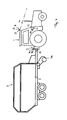
- the laser measuring device 13 when attaching a loading wagon 7 essentially scan a lying in the lane in front of the tractor 1 swath, which is run over by the tractor 1 and is to be picked up by the pickup 26 of the attached wagon 7.
- the scanning width of the scanning region 15 is advantageously adapted to the width of said pickup 26, for example, adjusted to 125% of the working width of the pickup 26.
- the entire swath can be scanned, advantageously the Schwadmitte can be determined from the point of maximum height of the swath and / or from the lateral edges of the sampled swath, their position or their transverse offset relative to the center of the lane of the tractor is determined.
- the power steering device 20 can generate a steering signal to drive the loader wagon 7 exactly over or on the swath to accommodate the latter of the pickup 26 clean.
- At least one other operating parameter of the tractor 1 and / or the loading wagon 7 can be controlled, for example, that larger When the windrow speed is reduced or vice versa with decreasing swath the driving speed is increased, and / or, for example, to the effect that with increasing swath size, the performance and / or speed of the receiving device of the loading wagon 7 is increased.
- Fig. 5 shows, when growing a plow lying in front of the tractor 1 bottom portion of the laser measuring device 13 are scanned, the scanning 15 is directed in response to the read identification data or preset data for the plow 8 to an area in front of the tractor 1, the left or is offset right across the lane center. If this is a reversible plow provided as this Fig. 5 1, the said scanning region 15 can be preset once to the right or once to the left depending on the turning position of the plow 8, in particular in such a way that the transitional region between a furrow furrow generated in a preceding lane is scanned to the still unprocessed field section becomes.
- the scanning region 15 can be preset more or less far transversely offset from the lane center of the tractor 1. From the then detected by the laser measuring device 13 position of said transition region between furrows and still unprocessed soil, in particular from the transverse offset of this transition region of the lane center and the geometry data of Plowing the power steering device 20 then generate a corresponding steering signal to guide the plow 8 exactly along said transition edge.
Landscapes
- Life Sciences & Earth Sciences (AREA)
- Engineering & Computer Science (AREA)
- Mechanical Engineering (AREA)
- Soil Sciences (AREA)
- Environmental Sciences (AREA)
- Length Measuring Devices By Optical Means (AREA)
- Guiding Agricultural Machines (AREA)
- Lifting Devices For Agricultural Implements (AREA)
- Soil Working Implements (AREA)
Abstract
Description
Die vorliegende Erfindung betrifft eine landwirtschaftliche Maschine mit einer Anbauvorrichtung zum Anbau verschiedener Anbaugeräte zur Erntegut- und/oder Bodenbearbeitung, einer Bodenerfassungseinrichtung zum berührungslosen Erfassen einer Boden- und/oder Erntegutkontur, sowie einer Steuervorrichtung zur Steuerung der landwirtschaftlichen Maschine und/oder des Anbaugeräts in Abhängigkeit der erfassten Boden- und/oder Erntegutkontur, wobei die Bodenerfassungseinrichtung zumindest eine Lasermessvorrichtung umfasst, deren Laserstrahl zum Abtasten der Boden- und/oder Erntegutkontur über einen Abtastbereich führbar ist.The present invention relates to an agricultural machine with an attachment for growing various implements for Erntegut- and / or soil cultivation, a ground detection device for contactless detection of a soil and / or Erntegutkontur, and a control device for controlling the agricultural machine and / or the attachment in dependence the detected soil and / or Erntegutkontur, wherein the soil detection device comprises at least one laser measuring device, the laser beam for scanning the soil and / or Erntegutkontur is feasible over a scanning range.
Bei Landmaschinen ist es vorteilhaft, diverse Arbeitsaggregate der Maschinen in Abhängigkeit der vor dem Arbeitsaggregat liegenden Bodenkontur bzw. Erntegutkontur zu steuern. Beispielsweise kann für Ladewagen vorgesehen werden, die sog. Pickup, also die Erntegutaufnahmevorrichtung, die üblicherweise eine rotierende Stachelwalze aufweist, sozusagen schwebend über den Boden zu führen. Hierzu wird mittels eines Bodensensors die Bodenkontur vor der Pickup erfasst, um die Letztere bei Bodenwellen anzuheben und in Senken abzusenken, um eine präzise Erntegutaufnahme zu erreichen, ohne auf den Boden aufzufahren. Es wurde auch schon vorgeschlagen, vgl.
Es wurde auch bereits schon vorgeschlagen, die Boden- bzw. Erntegutkontur eines von einem Feldhäcksler zu bearbeitenden Erntegutschwads mittels einer Lasermessvorrichtung zu bestimmen, deren Laserstrahl zum Abtasten der Boden- bzw. Erntegutkontur über einen Abtastbereich geführt wird, der in der Fahrspur des Schleppers ausreichend weit vor dem Schlepper liegt, vgl.
Die bei derartigen Lasermessvorrichtungen zu verarbeitenden Datenmengen sind aufgrund der eingehenden Geometriegrößen und der recht komplizierten Berechnung sehr hoch, insbesondere dann, wenn der Abtastbereich nicht klein gehalten werden kann und der Laserstrahl über eine größere Breite den zu bearbeitenden Feldabschnitt abscannen muss. Bei der Erfassung eines Schwads kann der Abtastbereich des Laserstrahls noch einigermaßen begrenzt gehalten werden. Bei anderen landwirtschaftlichen Aufgaben ist dies jedoch ungleich schwieriger. Beispielsweise beim Zetten gibt es keinen schmalen Schwad, der erfasst werden müsste, sondern einen ausgebreiteten Futterteppich, bei dem die Grenze zwischen schon aufgelockertem, gewendetem Erntegut und dem noch unbearbeiteten, dichteren und stärker zusammengesackten Erntegut zu unterscheiden wäre, um beispielsweise eine Lenkhilfe für die Lenkung des Schleppers geben zu können, d.h. an der besagten Bearbeitungskante entlangfahren zu können.The amounts of data to be processed in such laser measuring devices are due to the detailed geometry sizes and the rather complicated calculation very high, especially if the scanning range can not be kept small and the laser beam over a greater width must scan the field section to be processed. When detecting a swath, the scanning range of the laser beam can still be kept reasonably limited. However, this is much more difficult with other agricultural tasks. For example, when tedding there is no narrow swath that would have to be detected, but a spreading feed carpet, in which the boundary between already loosened, turned crop and the still unprocessed, denser and more collapsed crop would be different, for example, a steering aid for the steering to be able to give the tractor, ie to be able to drive along the said processing edge.
Eine weitere Schwierigkeit besteht darin, dass die für die jeweilige landwirtschaftliche Aufgabe zu erfassende Boden- bzw. Erntegutkontur in verschiedenen Bereichen angeordnet sein kann. Beispielsweise liegt die zu beobachtende Schnittkante beim Mähen üblicherweise deutlich zur Seite versetzt neben dem Schlepper, während der für eine Ballenpresse oder einen Ladewagen zu erfassende Erntegutschwad üblicherweise zentral in der Fahrspur des Schleppers liegt. Wird der Abtastbereich der Lasermessvorrichtung ausreichend breit eingestellt, um diese für verschiedene Aufgaben verschieden positionierten Boden- bzw. Erntegutkonturen erfassen zu können, fallen sehr große Datenmengen an, die von der Auswerteeinrichtung verarbeitet werden müssen. Hierdurch leidet die Erfassungsgeschwindigkeit, so dass bei höheren Fahrgeschwindigkeiten kein ausreichend schnelles Eingreifen in die Lenkung des Schleppers oder die Steuerung der Betriebsparameter des Anbaugeräts gewährleistet werden kann. Wird, um hier Abhilfe zu schaffen, der Abtastbereich weiter nach vorne, d.h. mit größerem Frontabstand, eingestellt, ergibt sich bei begrenzter Anbringungshöhe der Lasermessvorrichtung ein sehr flacher Abtastwinkel gegenüber der Horizontalen, wodurch die abgetasteten Konturen ähnlich einem zu schrägen Schnitt stark verzerrt werden. Zudem ergeben sich unerwünschte Ungenauigkeiten bei der Laufzeitmessung.Another difficulty is that the soil or Erntegutkontur to be recorded for the respective agricultural task can be arranged in different areas. For example, the cutting edge to be observed during mowing is usually clearly offset to the side next to the tractor, while the Erntegutschwad to be detected for a baler or a loading wagon is usually centrally located in the lane of the tractor. If the scanning range of the laser measuring device is adjusted to be sufficiently wide in order to be able to record these differently positioned soil or crop contours for different tasks, very large amounts of data accumulate, which have to be processed by the evaluation device. As a result, the detection speed suffers, so that at higher speeds no sufficiently fast intervention in the steering of the tractor or the control of the operating parameters of the implement can be guaranteed. If, to remedy this situation, the scanning range is set further forward, ie with a greater front distance, a very flat scanning angle with respect to the horizontal results at a limited mounting height of the laser measuring device, as a result of which the scanned contours are greatly distorted, similar to an oblique cut. In addition, there are unwanted inaccuracies in the transit time measurement.
Der vorliegenden Erfindung liegt daher die Aufgabe zugrunde, eine verbesserte landwirtschaftliche Maschine der genannten Art zu schaffen, die Nachteile des Standes der Technik vermeidet und Letzteren in vorteilhafter Weise weiterbildet. Insbesondere soll eine verbesserte Boden- bzw. Erntegutkontur-Abtastung mittels Laserstrahl erreicht werden, die einen ausreichend großen Abtastbereich besitzt, um für verschiedene Anbaugeräte verschieden ausgebildete und positionierte Boden- bzw. Erntegutkonturen präzise erfassen zu können, ohne hierbei übermäßige Datenmengen anfallen zu lassen.The present invention is therefore based on the object to provide an improved agricultural machine of the type mentioned, which avoids the disadvantages of the prior art and further develops the latter in an advantageous manner. In particular, an improved soil or crop contour scanning by means of a laser beam is to be achieved, which has a sufficiently large scanning area in order to be able to precisely record differently shaped and positioned soil or crop contours for different implements, without causing excessive amounts of data.
Erfindungsgemäß wird diese Aufgabe durch eine landwirtschaftliche Maschine gemäß Anspruch 1 gelöst. Bevorzugte Ausgestaltungen der Erfindung sind Gegenstand der abhängigen Ansprüche.According to the invention, this object is achieved by an agricultural machine according to claim 1. Preferred embodiments of the invention are the subject of the dependent claims.
Es wird also vorgeschlagen, den Abtastbereich der Lasermessvorrichtung individuell an das jeweils angebaute Anbaugerät anzupassen. Anstatt einen übermäßig großen, für alle Anbaugeräte und deren relevanten Boden- und Erntegutkonturen passenden Abtastbereich vorzusehen, wird mit kleineren Abtastbereichen gearbeitet, die jeweils für das angebaute Anbaugerät passend hinsichtlich Lage und Größe adaptiert sind. Erfindungsgemäß ist eine Erfassungsvorrichtung zur Erfassung des jeweils an die Anbauvorrichtung angebauten Anbaugeräts vorgesehen, wobei von einer Einstellvorrichtung der Abtastbereich der Lasermessvorrichtung in Abhängigkeit des jeweils erfassten Anbaugeräts eingestellt wird. Der Lasermessvorrichtung ist ein intelligentes Steuerungssystem zugeordnet, welches für verschiedene Anbaugeräte weiß, wo jeweils der zu beobachtende Bodenkonturabschnitt liegt und die Lasermessvorrichtung hinsichtlich ihres Abtastbereichs entsprechend ansteuert, so dass der Abtastbereich gezielt für das jeweilige Anbaugerät passt.It is therefore proposed to adapt the scanning range of the laser measuring device individually to the attached attachment. Instead of providing an excessively large, suitable for all attachments and their relevant soil and Erntegutkonturen scanning, is working with smaller sampling areas, which are adapted respectively for the mounted attachment in terms of location and size. According to the invention, a detection device is provided for detecting the attachment attached to the attachment device, wherein the scanning range of the laser measuring device is set by an adjustment device as a function of the respectively detected attachment. The laser measuring device is associated with an intelligent control system, which knows for different attachments, where in each case the observed floor contour section and the laser measuring device accordingly controls in terms of their scanning so that the scanning specifically for the respective attachment fits.
Vorteilhafterweise kann ein Datenbus vorgesehen sein, mittels dessen Anbaugeräte-Identifikationsdaten und Einstellungsdaten übertragen werden können. Insbesondere können die Erfassungsvorrichtung zur Erfassung des jeweils angebauten Anbaugeräts, die Einstellvorrichtung zur Einstellung des Abtastbereiches der Lasermessvorrichtung und das Steuerungssystem miteinander per Datenbus kommunizieren.Advantageously, a data bus can be provided, by means of which implement identification data and setting data can be transmitted. In particular, the detection device for detecting the respectively attached attachment, the adjusting device for adjusting the scanning range of the laser measuring device and the control system communicate with each other via data bus.
Die Erfassung des jeweiligen Anbaugeräts für die Voreinstellung des Abtastbereichs der Lasermessvorrichtung kann grundsätzlich in verschiedener Art und Weise erfolgen. In vorteilhafter Weiterbildung der Erfindung kann die Erfassung berührungslos erfolgen, wobei die Erfassungsvorrichtung ein Lesegerät zum Auslesen eines am Anbaugerät anbringbaren Datenspeichers beispielsweise in Form eines Transponderchips besitzen kann, wobei in besagtem Datenspeicher Anbaugeräte-Identifikationsdaten und/oder Einstelldaten für die Lasermessvorrichtung gespeichert sein können. Wird das Anbaugerät an die Anbauvorrichtung angedockt, werden die Daten von dem am Anbaugerät vorgesehenen Datenspeicher an das Lesegerät übertragen, wobei anhand der übertragenen Identifikationsdaten und/oder Einstelldaten die Einstellvorrichtung den Abtastbereich der Lasermessvorrichtung entsprechend voreinstellt. Alternativ oder zusätzlich zu einem solchen Transponderchip kann beispielsweise auch ein Barcodeleser vorgesehen sein, der einen am Anbaugerät angebrachten Barcode einlesen kann. Grundsätzlich können auch andere Datenspeicher- und Übertragungsmittel vorgesehen sein. Alternativ oder zusätzlich zu einer solchen vollautomatischen Datenübertragung kann auch eine manuelle oder halbautomatische Anbaugeräteerfassung vorgesehen sein, beispielsweise dergestalt, dass die Einstellvorrichtung zur Einstellung des Abtastbereiches der Lasermessvorrichtung eine Eingabevorrichtung beispielsweise in Form eines Touchscreens, eines Keyboards oder auch eines Magnetstreifenlesers aufweist, in den eine Datenkarte eingesteckt bzw. an dem eine solche Datenkarte vorbeigezogen werden muss. Eine solche manuelle Eingabemöglichkeit für die Anbaugeräte-Identifikationsdaten kann auch zusätzlich der vorbeschriebenen automatischen Erfassung vorgesehen sein, beispielsweise um bei Datenübertragungsproblemen trotzdem eine Voreinstellung des Laserabtastbereiches vornehmen zu können.The detection of the respective attachment for presetting the scanning range of the laser measuring device can basically be done in various ways. In an advantageous embodiment of the invention, the detection can be carried out without contact, wherein the detection device may have a reading device for attaching attachable to the attachment data memory, for example in the form of a transponder chip, wherein in said data storage attachment identification data and / or setting data for the laser measuring device can be stored. When the attachment is docked to the hitch, the data is transferred from the attached to the attachment data storage device to the reading device, wherein based on the transmitted identification data and / or setting data, the setting the preset range of the laser measuring device accordingly. As an alternative or in addition to such a transponder chip, it is also possible to provide, for example, a barcode reader which can read in a barcode attached to the attachment. In principle, other data storage and transmission means may be provided. Alternatively or in addition to such a fully automatic data transmission, manual or semi-automatic attachment detection can also be provided, for example such that the setting device for setting the scanning range of the laser measuring device has an input device, for example in the form of a touch screen, a keyboard or a magnetic stripe reader, into which a data card plugged in or on which such a data card must be pulled past. Such a manual input option for the implement identification data can also be provided in addition to the above-described automatic detection, for example in order to be able to make a default setting of the laser scanning range in the event of data transmission problems.
Die Voreinstellung des Laserstrahl-Abtastbereiches kann grundsätzlich in verschiedener Art und Weise erfolgen. Je nach Ausbildung des Laserscanners kann es beispielsweise vorteilhaft sein, einen horizontalen und/oder vertikalen Winkelbereich, in dem die Lasermessvorrichtung den Boden bzw. Erntegutteppich abscannt, einzuschränken, um nicht verwertbare Bereiche auszublenden und hierdurch die Datenmenge signifikant zu reduzieren. Die Einschränkung der Abtastwinkelbereiche bzw. die Ausblendung nicht brauchbarer Bereiche kann vorteilhafterweise softwaremäßig erfolgen, beispielsweise durch Ausblendung bzw. Ausfilterung der in einem nicht benötigten Bereich bereitgestellten Scandaten. Hierdurch kann Rechenzeit und Buskapazität eingespart werden.The default setting of the laser beam scanning range can basically be done in various ways. Depending on the design of the laser scanner, it may be advantageous, for example, to have a horizontal and / or vertical angle range, in which the laser measuring device scans the soil or Erntegutteppich to restrict so as to hide unrecognizable areas and thereby significantly reduce the amount of data. The restriction of the scanning angle ranges or the blanking of unusable ranges can advantageously be effected by software, for example by blanking or filtering out the scan data provided in a region which is not required. As a result, computing time and bus capacity can be saved.
Wird beispielsweise eine Lasermessvorrichtung verwendet, die mit einem Abtastwinkel von 70° arbeitet und durch kippbare Spiegel verschiedene Neigungswinkel zur Horizontalen aufnehmen kann, kann beispielsweise softwaremäßig von dem genannten Abtastwinkelbereich von beispielsweise 70° nur ein Ausschnitt von beispielsweise 35° verwendet werden und von den mehreren horizontalen Abtastwinkeln beispielsweise nur einer für die Auswertung herangezogen werden, während der Rest ausgeblendet bzw. ausgefiltert wird.If, for example, a laser measuring device is used which operates with a scanning angle of 70 ° and can record different tilt angles to the horizontal by means of tiltable mirrors, by way of example only a section of, for example, 35 ° of the mentioned scanning angle range of, for example, 70 ° can be used and of the several horizontal Scanning angles, for example, only one used for the evaluation, while the rest is hidden or filtered out.
Alternativ oder zusätzlich kann jedoch auch vorgesehen sein, nicht nur innerhalb eines vorgegebenen Abtastspektrums durch Ausblenden Unterbereiche auszuwählen, sondern auch darüber hinaus die Abtastspektren frei festzulegen bzw. über die voreingestellten Spektren hinauszugehen, beispielsweise dadurch, dass die Verkippung der Spiegel in der gewünschten Weise eingestellt wird.Alternatively or additionally, however, it may also be provided not only to select subregions within a given scanning spectrum by fading out but also to specify the scanning spectra freely or to go beyond the preset spectra, for example by setting the tilt of the mirrors in the desired manner ,
In Weiterbildung der Erfindung kann von der Einstellvorrichtung in Abhängigkeit des jeweils erfassten Anbaugeräts der Neigungswinkel des Laserstrahls gegenüber der Horizontalen variiert werden derart, dass der Abtastbereich für ein mit größerer Fahrgeschwindigkeit betriebenes Anbaugerät in Fahrtrichtung betrachtet weiter vorne liegend und für ein mit kleinerer Fahrgeschwindigkeit betriebenes Anbaugerät weniger weit vorne liegend angeordnet wird. Wird beispielsweise ein Ladewagen angebaut, mit dem recht schnell gefahren werden kann, wird die Lasermessvoreinrichtung entsprechend voreingestellt, um mit dem Laserstrahl relativ weit nach vorne zu blicken und einen relativ weit vor der Maschine liegenden Schwadabschnitt abzutasten. Wird andererseits beispielsweise eine Ballenpresse angebaut, die beispielsweise aufgrund eines älteren Modells langsamer zu betreiben ist, wird anhand der erfassten Daten der Ballenpresse die Lasermessvorrichtung derart voreingestellt, dass der Abtastbereich näher am Schlepper bzw. weniger weit vor dem Schlepper liegt, um bei ausreichender Vorlaufzeit eine höhere Genauigkeit der Konturabtastung zu erreichen.In a further development of the invention, the angle of inclination of the laser beam relative to the horizontal can be varied by the setting device in dependence on the respectively detected attachment such that the scanning range for a driven at a higher driving speed attachment viewed in the direction of travel lying ahead and less for an operated at a lower driving speed attachment is placed far in front. If, for example, a loader wagon is mounted, with which it is possible to drive quite quickly, the laser measuring device is pre-set to look relatively far forward with the laser beam and to scan a swath section lying relatively far in front of the machine. On the other hand, for example, a baler is grown, for example is slower to operate due to an older model, the laser measuring device is preset in such a way based on the recorded data of the baler that the scanning is closer to the tractor or less far from the tractor to achieve a higher accuracy of contour scanning with sufficient lead time.
Alternativ oder zusätzlich kann der Abtastbereich der Lasermessvorrichtung auch hinsichtlich seiner Abtastbreite und/oder hinsichtlich seiner Lage quer zur Fahrspur unterschiedlich voreingestellt werden, je nachdem, welches Anbaugerät genutzt wird. Wird beispielsweise ein Ladewagen angebaut, der eine große Aufnahmebreite an der Pickup besitzt, kann die Lasermessvorrichtung derart voreingestellt werden, dass ein relativ breiter Bereich in der Fahrspur vor dem Schlepper bzw. Ladewagen von der Lasermessvorrichtung erfasst wird. Da ein entsprechend breiter Schwad üblicherweise in der Fahrspur des Schleppers liegt, wird der Abtaststrahl der Lasermessvorrichtung über eine recht große Breite hin- und hergeführt, wobei der Abtastbereich im Wesentlichen in der Fahrspur des Schleppers vorgesehen wird. Wird andererseits beispielsweise ein Mähwerk angebaut, gilt es, die Bestandskante des noch ungemähten Ernteguts zu erfassen, die üblicherweise präzise begrenzt ist, d.h. sich nicht über eine große Breite erstreckt, und andererseits üblicherweise seitlich neben der Fahrspur des Schleppers liegt. Bei Erfassung eines entsprechenden Mähwerks als genutztes Anbaugerät kann aufgrund der bekannten Mähwerksbreite und dessen seitlicher Ausladung relativ zur Schlepperfahrspur der seitlich neben der Fahrspur des Schleppers liegende Bereich bestimmt werden, in dem die Bestandskante liegen muss, wenn der Schlepper auf Anschluss fährt, d.h. so fährt, dass unter möglichst großer Ausnutzung der Arbeitsbreite der Mähmaschine ohne Stehenlassen von Erntegut eine Bahn gemäht wird.Alternatively or additionally, the scanning range of the laser measuring device can also be preset differently with regard to its scanning width and / or with regard to its position transversely to the traffic lane, depending on which attachment is used. If, for example, a loading wagon is mounted which has a large receiving width at the pickup, the laser measuring device can be preset in such a way that a relatively wide area in the lane in front of the tractor or loader wagon is detected by the laser measuring device. Since a correspondingly wide swath usually lies in the lane of the tractor, the scanning beam of the laser measuring device is reciprocated over a fairly large width, the scanning area being provided substantially in the lane of the tractor. On the other hand, if, for example, a mower is being cultivated, it is necessary to detect the crop edge of the still uncut crop which is usually precisely confined, i. does not extend over a large width, and on the other hand is usually located laterally next to the lane of the tractor. Upon detection of a corresponding mower as a used attachment can be determined due to the known mower width and its lateral projection relative to the tractor lane of lying laterally next to the lane of the tractor area in which the stock edge must lie when the tractor is driving on connection, i. so drives that under the greatest possible utilization of the working width of the mower without leaving a crop a track is mowed.
In vorteilhafter Weiterbildung der Erfindung muss die Lasermessvorrichtung hierbei nicht zwangsweise auf eine jeweils gerade zu bearbeitende Boden- bzw. Erntegutkontur gerichtet werden. Je nach genutztem Anbaugerät kann es auch vorteilhaft sein, wenn die Lasermessvorrichtung so eingestellt wird, dass ein an sich gar nicht zu bearbeitender Feldabschnitt abgetastet wird, insbesondere ein neben der bearbeiteten Fahrgasse liegender Feldabschnitt, der zuvor in einer vorhergehenden Fahrgasse bereits bearbeitet wurde. Dort finden sich nämlich häufig leichter zu erfassende Konturen, beispielsweise dann, wenn Erntegut in einem Schwad abgelegt wurde. In vorteilhafter Weiterbildung der Erfindung kann in Abhängigkeit des erfassten Anbaugeräts der Abtastbereich außerhalb der Fahrspur und/oder außerhalb der Arbeitsbreite der Maschine auf ein bereits bearbeitetes Flächenstück gerichtet werden, in dem eine Bearbeitungskontur aus einer früheren Fahrgasse angeordnet ist, wobei vorteilhafterweise die Größe des Querversatzes des Abtastbereiches von der Mitte der Fahrspur der Maschine weg in Abhängigkeit des jeweils erfassten Anbaugeräts eingestellt wird. Vorteilhafterweise beinhalten die erfassten Identifikationsdaten und/oder Einstelldaten für das jeweilige Anbaugerät Angaben über die Arbeitsbreite und/oder die seitliche Ausladung des jeweiligen Anbaugeräts, so dass die Steuerung für die Lasermessvorrichtung weiß, wie weit bei korrektem Anschlussfahren eine zuvor erzeugte Erntegutkontur beispielsweise in Form eines Schwads oder eine erzeugte Bodenkontur beispielsweise in Form einer Ackerfurche seitlich beabstandet angeordnet sein müsste. Alternativ oder zusätzlich kann auch die Breite des Abtastbereiches entsprechend voreingestellt werden. Wird beispielsweise ein Schwader angebaut, kann aus der erfassten Arbeitsbreite des Schwaders und der bekannten, üblichen abgelegten Schwadposition die Lasermessvorrichtung den Bereich erfassen, in dem ein auf der zuvor befahrenen Fahrgasse abgelegter Schwad liegt, da die Steuerung weiß, wie weit seitlich der Schwad liegen muss, wenn korrekt auf Anschluss gefahren wird.In an advantageous development of the invention, the laser measuring device does not necessarily have to be directed to a respective soil or crop contour that is currently being processed. Depending on the implement used, it may also be advantageous if the laser measuring device is set so that a not to be machined field section is scanned, in particular one next to the processed Trunk lying field section, which was previously processed in a previous tram. Namely, there are often easier-to-grasp contours, for example, when crop was stored in a swath. In an advantageous embodiment of the invention, depending on the detected attachment scanning outside the lane and / or outside the working width of the machine can be directed to an already processed surface piece in which a machining contour is arranged from an earlier tram, advantageously the size of the transverse offset of Scanning range is set away from the center of the lane of the machine depending on the respectively detected attachment. Advantageously, the detected identification data and / or setting data for the respective attachment information about the working width and / or the lateral projection of the respective attachment, so that the control for the laser measuring device knows how far with correct connection driving a previously generated crop contour, for example in the form of a swath or a generated bottom contour would have to be arranged laterally spaced, for example in the form of a furrow. Alternatively or additionally, the width of the scanning range can also be preset accordingly. If, for example, a rake is being cultivated, the laser measuring device can detect the area in which a windrow deposited on the previously traveled lane lies, because the controller knows how far to the side of the windrow must lie from the detected working width of the rake and the known, commonly stored swath position , if correctly driven on connection.
Um die Datenmenge für die Auswertung der Lasersignale und deren Laufzeit klein zu halten, kann in Weiterbildung der Erfindung vorteilhafterweise vorgesehen sein, dass der Abtastbereich in Abhängigkeit des jeweils erfassten Anbaugeräts auf eine Abtastbreite eingestellt wird, die weniger als 150 % der Arbeitsbreite des Anbaugeräts beträgt. Je nach Anbaugerät kann die Abtastbreite auch auf weniger als 75 % der Arbeitsbreite des angebauten Anbaugeräts eingestellt werden. Wird beispielsweise ein Ladewagen angebaut, wird die Abtastbreite des Laserstrahls vorteilhafterweise auf einen Bereich von etwa 100 % bis 150 % der Breite der Pickup des Ladewagens eingestellt, da hier entsprechend breite Erntegutschwade aufgenommen werden können. Wird andererseits beispielsweise bei einem angebauten Mähwerk die Bestandskante des noch ungemähten Ernteguts erfasst, kann die Abtastbreite deutlich kleiner als die Arbeitsbreite der Mähmaschine eingestellt werden, da die Bestandskante üblicherweise scharf abgegrenzt ist und auch hinsichtlich ihrer Lage nur in einem kleinen Bereich variieren kann, der nur einen Bruchteil der Arbeitsbreite der Mähmaschine beträgt. Beispielsweise kann es bei Mähmaschinen oder auch anderen Anbaugeräten, bei denen nur eine relativ schmale Boden- bzw. Erntegutkontur abzutasten ist, ausreichend sein, die Abtastbreite des Laserstrahls auf weniger als 50 % der Arbeitsbreite der Anbaumaschine einzustellen.In order to keep the amount of data for the evaluation of the laser signals and their runtime small, can be advantageously provided in development of the invention that the scanning is set depending on the respectively detected attachment to a scan width which is less than 150% of the working width of the attachment. Depending on the attachment, the scan width can also be set to less than 75% of the working width of the mounted implement. If, for example, a loader wagon is mounted, the scanning width of the laser beam is advantageously set to a range of approximately 100% to 150% of the width of the pickup of the wagon, since it accommodates correspondingly broad crop swaths can be. If, on the other hand, for example, the crop edge of the still unmown crop is detected in an attached mower, the sampling width can be set much smaller than the working width of the mower because the crop edge is usually sharply demarcated and can vary only in a small area in terms of their location, the only a fraction of the working width of the mower. For example, in mowers or other attachments where only a relatively narrow soil or crop contour is to be scanned, it may be sufficient to set the scan width of the laser beam to less than 50% of the working width of the attachment machine.
Die Einstellvorrichtung zur Einstellung des Abtastbereiches der Lasermessvorrichtung kann die Voreinstellungen grundsätzlich in verschiedener Art und Weise bestimmen. Beispielsweise können die Abtastbereiche aus den Identifikationsdaten und damit verbundenen Angaben zur Arbeitsbreite des jeweiligen Anbaugeräts berechnet werden. Alternativ oder zusätzlich kann die Einstellvorrichtung aber auch einen Datenspeicher aufweisen bzw. mit einem solchen Datenspeicher per Daten-übertragungsvorrichtung verbindbar sein, um aus dem genannten Datenspeicher für ein jeweiliges Anbaugerät zugehörige Voreinstellungsdaten auszulesen und für die Einstellung des Abtastbereichs zu verwenden. In dem genannten Datenspeicher sind hierbei vorteilhafterweise ähnlich einer Bibliothek eine Mehrzahl von Datensätzen für die genannten Voreinstellungsdaten von verschiedenen Anbaugeräten speicherbar, so dass dann, wenn ein jeweils angekoppeltes Anbaugerät erfasst ist, aus dem Datenspeicher nur die passenden Voreinstellungsdaten ausgelesen werden müssen, um den Abtastbereich der Lasermessvorrichtung für das jeweilige Anbaugerät richtig einzustellen.The setting device for setting the scanning range of the laser measuring device can basically determine the default settings in various ways. For example, the scanning ranges can be calculated from the identification data and associated information about the working width of the respective attachment. Alternatively or additionally, however, the setting device can also have a data memory or be connectable to such a data memory by means of a data transmission device in order to read from the data memory for a respective attachment associated default data and to use for setting the scanning range. In the aforementioned data memory, a plurality of data sets for the aforementioned preset data of different attachments can advantageously be stored here, so that when a respectively coupled attachment is detected, only the appropriate preset data has to be read from the data memory in order to obtain the scan range of the Set the laser measuring device for the respective implement correctly.
Die von der Lasermessvorrichtung bestimmte Boden- bzw. Erntegutkontur, deren Größe und/oder deren Lage kann grundsätzlich für verschiedene Steuerungsaufgaben verwendet werden. In vorteilhafter Weiterbildung der Erfindung kann hierbei eine Lenkhilfevorrichtung vorgesehen sein, die in Abhängigkeit der von der Lasermessvorrichtung jeweils bestimmten Boden- bzw. Erntegutkontur und deren Lage relativ zur landwirtschaftlichen Maschine ein Lenksignal bereitstellt, um an der genannten Boden- bzw. Erntegutkontur entlangfahren zu können. Das genannte Lenksignal kann hierbei bei halbautomatischer Lenkhilfevorrichtung beispielsweise ein auf einem Display angezeigtes Signal beispielsweise in Form eines nach rechts oder links weisenden Pfeiles sein, anhand dessen der Schlepperführer sieht, ob er nach rechts oder links lenken muss. Alternativ oder zusätzlich kann das Lenksignal auch ein Ansteuersignal für eine automatisch arbeitende Lenkvorrichtung sein, die den Lenkeinschlag der landwirtschaftlichen Maschine in Abhängigkeit des genannten Lenksignals automatisch steuert.The soil or Erntegutkontur determined by the laser measuring device, their size and / or their location can basically be used for various control tasks. In an advantageous development of the invention, a power steering device may be provided which provides a steering signal in dependence on the ground or crop contour respectively determined by the laser measuring device and its position relative to the agricultural machine in order to be able to act on the said machine To be able to drive along the soil or crop contour. In the case of a semiautomatic power steering device, said steering signal may, for example, be a signal displayed on a display, for example in the form of an arrow pointing to the right or left, on the basis of which the tractor operator sees whether he has to steer to the right or left. Alternatively or additionally, the steering signal may also be a drive signal for an automatically operating steering device which automatically controls the steering angle of the agricultural machine as a function of said steering signal.
Die Lenkhilfevorrichtung umfasst hierbei vorteilhafterweise eine Auswerteeinrichtung, die in Abhängigkeit des jeweils erfassten Anbaugeräts und dessen Arbeitsbreite sowie der erfassten Lage der Boden- bzw. Erntegutkontur das Lenksignal generiert. Vorteilhafterweise kann hierbei in der vorgenannten Weise eine Bearbeitungskante aus einem bereits bearbeiteten Flächenstück des Feldes aus einer früheren Fahrgasse abgetastet und herangezogen werden. Beispielsweise kann bei Anbau eines Schwaders ein in einer vorherigen Fahrgasse abgelegter Schwad, der bei Befahren der aktuellen Fahrgasse neben der landwirtschaftlichen Maschine und deren Arbeitsbreite liegt, erfasst und für das Lenksignal herangezogen werden, so dass die landwirtschaftliche Maschine in einem vorbestimmten Abstand seitlich neben dem genannten Schwad entlangfährt. Ähnlich kann bei Anbau eines Zetters der aufgelockerte Erntegutteppich abgetastet werden, der in einer vorherigen Fahrgasse aufgelockert wurde, wobei insbesondere der Übergang zwischen dem schon aufgelockerten Futterteppichbereich und dem noch nicht aufgelockerten Futterteppichbereich bestimmt werden kann. Das Lenksignal kann hieraus derart generiert werden, dass die aktuelle Fahrgasse so gelegt wird, dass die Arbeitsbreite des Zetters geringfügig mit dem schon aufgelockerten Bereich überlappt, um einerseits die Arbeitsbreite des Zetters möglichst vollständig zu nutzen, andererseits jedoch ein vollständiges Zetten ohne unbearbeitete Übergangsbereiche zu erreichen.In this case, the power steering device advantageously comprises an evaluation device which generates the steering signal as a function of the respectively grasped attachment and its working width as well as the detected position of the ground or crop contour. Advantageously, in this case, a machining edge can be scanned from an already processed area of the field from an earlier tram and used in the aforementioned manner. For example, when installing a rake a windrow stored in a previous lane, which is when driving the current tram next to the agricultural machine and its working width, detected and used for the steering signal, so that the agricultural machine at a predetermined distance laterally next to said Schwad drives along. Similarly, when cultivating a tedder, the loosened crop carpet can be scanned, which has been loosened in a previous lane, in particular, the transition between the already loosened feed carpet area and the not yet loosened feed carpet area can be determined. The steering signal can be generated in such a way that the current tramline is placed so that the working width of the tentter overlaps slightly with the already loosened area, on the one hand to use the working width of the tentter as completely as possible, but on the other hand to achieve complete tedding without unprocessed transition areas ,
Alternativ oder zusätzlich zu einer solchen Lenkhilfe kann die variable Lasermessvorrichtung auch dazu genutzt werden, in Abhängigkeit der erfassten Boden - und/oder Erntegutkontur, deren Größe und/oder Beschaffenheit und/oder Lage zumindest einen weiteren Maschinen- oder Anbaugeräte-Betriebsparameter zu steuern, beispielsweise eine Drehgeschwindigkeit eines Arbeitsrotors, eine Arbeitshöhe eines Arbeitsaggregats oder die Leistungszufuhr zu einem Antrieb oder die Fahrgeschwindigkeit.As an alternative or in addition to such a steering aid, the variable laser measuring device can also be used in dependence on the detected soil and / or crop contour, its size and / or condition and / or position at least control another machine or attachment operating parameters, such as a rotational speed of a working rotor, a working height of a working unit or the power supply to a drive or the driving speed.
Vorteilhafterweise kann in Abhängigkeit des jeweils erfassten bzw. identifizierten Anbaugerätes die Auswertung der von der Lasermessvorrichtung bereitgestellten Daten und die hieraus abgeleiteten Funktionen und Befehle variiert werden. Wird beispielsweise als Anbaugerät ein Ladewagen vorgesehen, kann eine Auswerteeinheit der Steuervorrichtung die von der Lasermessvorrichtung bereitgestellten Daten dahingehend auswerten, dass eine Schwadkontur bestimmt wird und/oder das Querschnittsprofil der abgescannten Erntegutbereiche, beispielsweise um in Abhängigkeit hiervon die Leistung und Aufnahmegeschwindigkeit der Pickup des Ladewagens anzupassen. Wird indes beispielsweise ein Mähwerk angebaut, ist die Kontur des Ernteguts bzw. dessen Querschnittsprofil weniger interessant, so dass die Auswerteeinheit von der Erfassungsvorrichtung dahingehend informiert werden kann, dass die Datenauswertung hinsichtlich des Konturprofils unterlassen wird und stattdessen nur eine Mähkante und/oder die Grashöhe bestimmt wird. Durch die jeweils individuell an das Anbaugerät angepasste Auswertung der von der Lasermessvorrichtung erfassten und bereitgestellten Daten und/oder der hieraus abgeleiteten Funktionen und Steuerungsbefehle wie beispielsweise Lenkhilfesignale oder Steuerbefehle zur Einstellung der angebauten Anbaugeräte können die durchzuführenden Rechenoperationen und die benötigten Datenkapazitäten signifikant reduziert werden.Advantageously, the evaluation of the data provided by the laser measuring device and the functions and commands derived therefrom can be varied depending on the respectively detected or identified attachment. If, for example, a loading wagon is provided as an attachment, an evaluation unit of the control device can evaluate the data provided by the laser measuring device to determine a swath contour and / or the cross-sectional profile of the scanned crop regions, for example to adapt the performance and picking speed of the pickup truck to the loader depending thereon , However, if, for example, a mower is cultivated, the contour of the crop or its cross-sectional profile is less interesting, so that the evaluation of the detection device can be informed that the data evaluation is omitted with respect to the contour profile and instead determined only a Mähkante and / or the grass height becomes. By individually adapted to the attachment evaluation of the detected and provided by the laser measuring device data and / or the derived functions and control commands such as steering assistance signals or commands to adjust the attached implements, the arithmetic operations to be performed and the required data capacities can be significantly reduced.
Die Erfindung wird nachfolgend anhand eines bevorzugten Ausführungsbeispiels und zugehöriger Zeichnungen näher erläutert. In den Zeichnungen zeigen:
- Fig. 1:
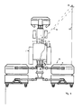
- eine schematische Draufsicht auf eine landwirtschaftliche Maschine in Form eines Schleppers mit einer daran angebauten Mähwerkskombination, wobei die am Schlepper angebrachte Lasermessvorrichtung mit ihrem Abtastbereich eine seitlich neben dem Schlepper liegende Bestandskante des noch ungemähten Ernteguts abtastet,
- Fig. 2:
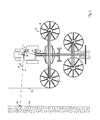
- eine schematische Draufsicht auf die landwirtschaftliche Maschine aus
Fig. 1 , wobei in diesem Fall ein Schwader als Anbaugerät angebaut ist und die Lasermessvorrichtung einen bereits abgelegten Schwad seitlich neben der zu bearbeitenden Fahrgasse erfasst, - Fig. 3 :
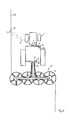
- eine schematische Draufsicht auf die landwirtschaftliche Maschine aus den vorhergehenden Figuren, wobei in diesem Fall als Anbaugerät ein Zetter als Anbaugerät angebaut ist und die Lasermessvorrichtung einen Übergangsbereich des schon aufgelockerten Futtergutteppichs aus der vorangehenden Fahrgasse und den noch nicht aufgelockerten Futtergutteppich der aktuellen Fahrgasse abtastet,
- Fig. 4:
- eine schematische Seitenansicht der landwirtschaftlichen Maschine aus den vorhergehenden Figuren, wobei in diesem Fall ein Ladewagen als Anbaugerät angebaut ist und die Lasermessvorrichtung einen in der Fahrspur des Schleppers liegenden Schwad abtastet, und
- Fig. 5:
- eine schematische Seitenansicht der landwirtschaftlichen Maschine aus den vorhergehenden Figuren, wobei in diesem Fall ein Wendepflug als Anbaugerät angebaut ist und die Lasermessvorrichtung den Übergangsbereich zwischen schon eingebrachten Ackerfurchen und noch unbeackertem Bodenbereich abtastet, wobei die Lasermessvorrichtung den Abtastbereich je nach Wendestellung des Wendepflugs einmal nach rechts versetzt und einmal nach links versetzt vorsieht.
- Fig. 1:
- a schematic plan view of an agricultural machine in the form of a tractor with a mowing combination attached thereto, wherein the attached to the tractor laser measuring device with her Scanning area scans a laterally adjacent to the tractor stock edge of the still uncut crop,
- Fig. 2:
- a schematic plan view of the agricultural machine
Fig. 1 , in which case a rake is mounted as an attachment and the laser measuring device detects an already deposited swath laterally next to the tramline to be processed, - 3:
- a schematic plan view of the agricultural machine of the preceding figures, in which case a tiller is attached as an attachment as an attachment and the laser measuring device scans a transition region of already loosened Futtergutteppichs from the previous tram and not yet loosened Futtergutteppich the current tram,
- 4:
- a schematic side view of the agricultural machine of the preceding figures, in which case a loader wagon is mounted as an attachment and the laser measuring device scans a lying in the lane of the tractor swath, and
- Fig. 5:
- a schematic side view of the agricultural machine of the preceding figures, in which case a reversible plow is mounted as an attachment and the laser measuring device scans the transition region between already introduced furrows and still untapped soil area, the laser measuring device, the scanning depending on the turning position of the reversible plow once to the right and once offset to the left.
Wie
An dem Schlepper 1 ist hierbei vorteilhafterweise eine Erfassungsvorrichtung 16 vorgesehen, die selbsttätige erfasst, welches Anbaugerät an den Schlepper 1 angebaut ist. Die genannte Erfassungsvorrichtung 16 kann hierbei eine berührungslos, beispielsweise im Radiofrequenzbereich arbeitende Sende- /Empfangseinrichtung mit einem Lesegerät 18 umfassen, um aus einem Datenspeicher 19, der an dem Anbaugerät 3 angebracht ist, Daten auslesen zu können, um das genannte Gerät zu identifizieren und/oder verschiedene Betriebsparameter in Abhängigkeit der ausgelesenen Daten einstellen zu können. Der genannte Datenspeicher 19 kann hierbei beispielsweise ein Transponderchip sein, der mit dem genannten Lesegerät 18 kommuniziert, welches vorteilhafterweise im Bereich der Anbauvorrichtung 2 angebracht sein kann. In dem Datenspeicher 19, der an dem Anbaugerät 3 angebracht ist, können insbesondere Anbaugeräte-Identifikationsdaten gespeichert sein, die Geometriedaten zu dem jeweiligen Anbaugerät wie beispielsweise dessen Arbeitsbreite, dessen seitliche Ausladung oder auch betriebstypische Parameter wie übliche Arbeitsgeschwindigkeit oder Ablagebereich beispielsweise eines abzulegenden Schwads umfassen können. Alternativ oder zusätzlich können in dem genannten Datenspeicher 19 Einstellungsdaten bzw. Steuerungsdaten gespeichert sein, die für die Voreinstellung diverser Betriebsparameter an dem Schlepper 1 und/oder dem Anbaugerät 3 genutzt werden können, insbesondere für die Voreinstellung einer Lasermessvorrichtung 13, die an dem Schlepper 1 angebracht sein kann.On the tractor 1 here a
Wie
Die Lasermessvorrichtung 13 kann hierbei mit nur einem Laserkopf 21 arbeiten, wobei diesem Laserkopf 21 vorteilhafterweise eine Umlenkvorrichtung beispielsweise in Form eines kipp- und/oder schwenkbaren Spiegels zugeordnet sein kann, um den von dem Laserkopf 21 abgegebenen Laserstrahl in verschiedene Richtungen lenken zu können. Alternativ oder zusätzlich kann die Lasermessvorrichtung 13 auch mehrere Laserköpfe 21 umfassen, die vorteilhafterweise in verschiedene Richtungen blicken, um verschiedene Bodenabschnitte vor und seitlich neben dem Schlepper 1 abtasten zu können. Gegebenenfalls kann auch hier einem oder allen der Laserköpfe eine Umlenkvorrichtung der genannten Art zugeordnet sein, um den jeweils abgegebenen Laserstrahl 14 in die gewünschte Richtung bzw. in verschiedene Richtungen lenken zu können.The
Die Lasermessvorrichtung 13 umfasst weiterhin in an sich bekannter Weise einen Laufzeitmesser, der von dem jeweiligen Konturpunkt reflektierte Laserstrahlung erfasst und die Laufzeit des Laserstrahls vom Laserkopf 21 zu dem Konturpunkt bzw. vom Konturpunkt zum genannten Laserkopf 21 bestimmt und hieraus die Entfernung des Konturpunkts bestimmt. Vorteilhafterweise kann der genannte Laserstrahl 14 hierbei über einen Abtastbereich 15 hin- und hergeführt werden, beispielsweise in einer Ebene von rechts nach links und zurück verschwenkt werden oder entlang eines Kreises bzw. eines Ovals oder einer Ellipse zyklisch hin- und hergeführt werden, um einen bestimmten, begrenzten Bereich des Bodens oder des darauf angeordneten Ernteguts abzutasten. Vorteilhafterweise ist der Laserstrahl 14 hierbei gegenüber einer horizontalen Ebene schräg nach unten/vorne geneigt, wie dies
Der Abtastbereich 15 der Lasermessvorrichtung 13 wird hierbei vorteilhafterweise in Abhängigkeit des jeweiligen Anbaugeräts 3 voreingestellt, das von der vorgenannten Erfassungsvorrichtung 16 am Schlepper 1 erkannt wird. Die hierzu der Lasermessvorrichtung 13 zugeordnete Einstellvorrichtung 17 stellt vorteilhafterweise automatisch für verschiedene, jeweils erkannte Anbaugeräte 3 verschiedene Abtastbereiche 15 ein.The
Ist beispielsweise, wie
Der Querversatz des Abtastbereiches 15 wird hierbei in Abhängigkeit der ausgelesenen Arbeitsbreite der Mähmaschine 4 derart bestimmt, dass ein Bereich abgetastet wird, in dem die genannte Bestandskante 22 bei einigermaßenem Anschlussfahren seitlich von der Fahrspur des Schleppers 1 beabstandet liegen müsste, vgl.
Wird indes, wie
Der Abtastbereich 15 kann hierbei in Fahrrichtung betrachtet auf Höhe des Schleppers 1 eingestellt sein, ggf. aber auch ein Stück weit voraus angeordnet sein, um genügend Reaktionszeit für die Steuerung zu haben.The
Aus dem erfassten Schwad 24 und dessen Lage relativ zum Schlepper 1 sowie den bekannten Daten zur Geometrie des Anbaugeräts 3 kann eine dem Schlepper 1 zugeordnete Lenkhilfevorrichtung 20 ein Lenksignal generieren, um den Schlepper 1 in einem vorbestimmten Abstand an dem erfassten Schwad 24 entlang zu führen und hierdurch den noch unbearbeiteten Feldbereich exakt unter näherungsweise voller Ausnutzung der Arbeitsbreite des Schwaders 5 zu bearbeiten.From the detected
Wie
Wie
Alternativ oder zusätzlich kann beispielsweise aus der Höhe des erfassten Schwads und/oder der Breite des erfassten Schwads und/oder der Querschnittsfläche des erfassten Schwads auch zumindest ein anderer Betriebsparameter des Schleppers 1 und/oder des Ladewagens 7 gesteuert werden, beispielsweise dahingehend, dass bei größer werdendem Schwad die Fahrgeschwindigkeit ermäßigt wird oder umgekehrt bei kleiner werdendem Schwad die Fahrgeschwindigkeit erhöht wird, und/oder beispielsweise dahingehend, dass bei zunehmender Schwadgröße die Leistung und/oder Geschwindigkeit der Aufnahmevorrichtung des Ladewagens 7 erhöht wird.Alternatively or additionally, for example, from the height of the detected swath and / or the width of the detected swath and / or the cross-sectional area of the detected swath, at least one other operating parameter of the tractor 1 and / or the
Wie
Claims (15)
Applications Claiming Priority (1)
| Application Number | Priority Date | Filing Date | Title |
|---|---|---|---|
| DE102011100054A DE102011100054A1 (en) | 2011-04-29 | 2011-04-29 | Agricultural machine |
Publications (3)
| Publication Number | Publication Date |
|---|---|
| EP2517543A2 true EP2517543A2 (en) | 2012-10-31 |
| EP2517543A3 EP2517543A3 (en) | 2012-11-07 |
| EP2517543B1 EP2517543B1 (en) | 2014-06-11 |
Family
ID=46146504
Family Applications (1)
| Application Number | Title | Priority Date | Filing Date |
|---|---|---|---|
| EP12002876.6A Active EP2517543B1 (en) | 2011-04-29 | 2012-04-24 | Agricultural machine |
Country Status (3)
| Country | Link |
|---|---|
| EP (1) | EP2517543B1 (en) |
| DE (1) | DE102011100054A1 (en) |
| ES (1) | ES2496000T3 (en) |
Cited By (13)
| Publication number | Priority date | Publication date | Assignee | Title |
|---|---|---|---|---|
| WO2015065174A1 (en) | 2013-10-29 | 2015-05-07 | Forage Innovations B.V. | Agricultural vehicle adapted for curve driving |
| US20170118915A1 (en) * | 2015-11-03 | 2017-05-04 | Claas Selbstfahrende Erntemaschinen Gmbh | Surroundings detection device for agricultural work machines |
| BE1024929B1 (en) * | 2017-05-09 | 2018-08-13 | Cnh Industrial Belgium Nv | IMPROVEMENTS IN OR RELATING TO VEHICLE / TRAILER COMBINATIONS |
| BE1024928B1 (en) * | 2017-05-09 | 2018-08-13 | Cnh Industrial Belgium Nv | IMPROVEMENTS IN OR RELATING TO TRACTOR / BALER PRESS COMBINATIONS |
| EP3381252A1 (en) * | 2017-03-28 | 2018-10-03 | AGCO Feucht GmbH | Steering assistance system for an agricultural tractor and implement combination |
| EP3461313A1 (en) * | 2017-09-28 | 2019-04-03 | CLAAS E-Systems KGaA mbH & Co KG | Agricultural machine |
| US10431016B2 (en) | 2017-01-23 | 2019-10-01 | Deere & Company | Method and device for identification of an implement |
| WO2020037003A1 (en) | 2018-08-13 | 2020-02-20 | Raven Industries, Inc. | Comparative agricultural obstacle monitor and guidance system and method for same |
| EP3818799A1 (en) * | 2019-11-08 | 2021-05-12 | CLAAS E-Systems GmbH | Agricultural machine |
| EP3909417A1 (en) * | 2020-05-15 | 2021-11-17 | CNH Industrial Belgium N.V. | Agricultural raking system and method for automatic settings |
| EP3912455A1 (en) * | 2020-05-18 | 2021-11-24 | CLAAS Saulgau GmbH | Merger control device and merger |
| US11659785B2 (en) | 2019-10-23 | 2023-05-30 | Cnh Industrial America Llc | Method and system for controlling the height of an agricultural implement relative to the ground |
| US12366860B2 (en) | 2020-12-11 | 2025-07-22 | Raven Industries, Inc. | Sensor fusion in agricultural vehicle steering |
Families Citing this family (4)
| Publication number | Priority date | Publication date | Assignee | Title |
|---|---|---|---|---|
| US20180116121A1 (en) * | 2016-10-28 | 2018-05-03 | Deere & Company | Methods and systems for more efficient hay creation |
| US20180116124A1 (en) * | 2016-10-28 | 2018-05-03 | Deere & Company | Methods and systems for more efficient hay creation |
| US12120972B2 (en) | 2021-09-28 | 2024-10-22 | Deere & Company | Agricultural machine control using work quality based on in situ operation sensing |
| US12114601B2 (en) * | 2021-09-28 | 2024-10-15 | Deere & Company | Agricultural machine speed control based on work quality metrics |
Citations (4)
| Publication number | Priority date | Publication date | Assignee | Title |
|---|---|---|---|---|
| DE19859875A1 (en) | 1998-12-23 | 2000-06-29 | Claas Saulgau Gmbh | Control for agricultural work machine |
| EP1356729B1 (en) | 2002-04-02 | 2005-11-09 | CLAAS Selbstfahrende Erntemaschinen GmbH | Mesuring device for agricultural machine |
| EP1813142B1 (en) | 2006-01-31 | 2009-07-08 | Alois Pöttinger Maschinenfabrik GmbH | Agricultural machine |
| EP0887660B1 (en) | 1997-06-25 | 2010-06-09 | CLAAS Selbstfahrende Erntemaschinen GmbH | Device mounted on agricultural machines for contactless mapping of ground surface contours and accompanying method |
Family Cites Families (4)
| Publication number | Priority date | Publication date | Assignee | Title |
|---|---|---|---|---|
| DE10129136A1 (en) * | 2001-06-16 | 2002-12-19 | Deere & Co | Device for the automatic steering of an agricultural work vehicle |
| DE10204702A1 (en) * | 2002-02-05 | 2003-08-14 | Claas Selbstfahr Erntemasch | Location system on self-propelled agricultural machines |
| DE10208012A1 (en) * | 2002-02-26 | 2003-09-04 | Claas Selbstfahr Erntemasch | Tracking system on an agricultural machine |
| EP2057875A1 (en) * | 2007-11-08 | 2009-05-13 | Leibniz-Institut für Agrartechnik Potsdam-Bornim e.V. (ATB) | Method and assembly for recording plant resources on agricultural machines |
-
2011
- 2011-04-29 DE DE102011100054A patent/DE102011100054A1/en not_active Withdrawn
-
2012
- 2012-04-24 EP EP12002876.6A patent/EP2517543B1/en active Active
- 2012-04-24 ES ES12002876.6T patent/ES2496000T3/en active Active
Patent Citations (4)
| Publication number | Priority date | Publication date | Assignee | Title |
|---|---|---|---|---|
| EP0887660B1 (en) | 1997-06-25 | 2010-06-09 | CLAAS Selbstfahrende Erntemaschinen GmbH | Device mounted on agricultural machines for contactless mapping of ground surface contours and accompanying method |
| DE19859875A1 (en) | 1998-12-23 | 2000-06-29 | Claas Saulgau Gmbh | Control for agricultural work machine |
| EP1356729B1 (en) | 2002-04-02 | 2005-11-09 | CLAAS Selbstfahrende Erntemaschinen GmbH | Mesuring device for agricultural machine |
| EP1813142B1 (en) | 2006-01-31 | 2009-07-08 | Alois Pöttinger Maschinenfabrik GmbH | Agricultural machine |
Cited By (34)
| Publication number | Priority date | Publication date | Assignee | Title |
|---|---|---|---|---|
| WO2015065174A1 (en) | 2013-10-29 | 2015-05-07 | Forage Innovations B.V. | Agricultural vehicle adapted for curve driving |
| US20170118915A1 (en) * | 2015-11-03 | 2017-05-04 | Claas Selbstfahrende Erntemaschinen Gmbh | Surroundings detection device for agricultural work machines |
| EP3165062A1 (en) * | 2015-11-03 | 2017-05-10 | CLAAS Selbstfahrende Erntemaschinen GmbH | Environment detection device for agricultural vehicle |
| US20220000025A1 (en) * | 2015-11-03 | 2022-01-06 | Claas Selbstfahrende Erntemaschinen Gmbh | Surroundings detection device for agricultural work machines |
| US11122740B2 (en) | 2015-11-03 | 2021-09-21 | CLAAS Scibstfahrende Erntemaschinen GmbH | Surroundings detection device for agricultural work machines |
| US11716930B2 (en) * | 2015-11-03 | 2023-08-08 | Claas Selbstfahrende Erntemaschinen Gmbh | Surroundings detection device for agricultural work machines |
| RU2731733C2 (en) * | 2015-11-03 | 2020-09-08 | КЛААС Зельбстфаренде Эрнтемашинен ГмбХ | Agricultural working machine with device for detecting surrounding space |
| US10431016B2 (en) | 2017-01-23 | 2019-10-01 | Deere & Company | Method and device for identification of an implement |
| EP3381252A1 (en) * | 2017-03-28 | 2018-10-03 | AGCO Feucht GmbH | Steering assistance system for an agricultural tractor and implement combination |
| CN110612021A (en) * | 2017-05-09 | 2019-12-24 | 凯斯纽荷兰(中国)管理有限公司 | Improvements in or related to vehicle-trailer combinations |
| US11185004B2 (en) | 2017-05-09 | 2021-11-30 | Cnh Industrial America Llc | Vehicle-trailer combinations |
| CN110740632A (en) * | 2017-05-09 | 2020-01-31 | 凯斯纽荷兰(中国)管理有限公司 | Improvements in or related to tractor-baler combinations |
| US11812680B2 (en) | 2017-05-09 | 2023-11-14 | Cnh Industrial America Llc | Tractor-baler combinations |
| WO2018206678A1 (en) * | 2017-05-09 | 2018-11-15 | Cnh Industrial Belgium Nv | Improvements in or relating to tractor-baler combinations |
| RU2738423C1 (en) * | 2017-05-09 | 2020-12-14 | СиЭнЭйч ИНДАСТРИАЛ БЕЛДЖИУМ НВ | Combination of movable vehicle and trailer and method of controlling combination of vehicle and trailer |
| AU2018265089B2 (en) * | 2017-05-09 | 2021-03-04 | Cnh Industrial Belgium Nv | Improvements in or relating to tractor-baler combinations |
| AU2018265094B2 (en) * | 2017-05-09 | 2021-04-08 | Cnh Industrial Belgium Nv | Improvements in or relating to vehicle-trailer combinations |
| WO2018206683A1 (en) * | 2017-05-09 | 2018-11-15 | Cnh Industrial Belgium Nv | Improvements in or relating to vehicle-trailer combinations |
| BE1024928B1 (en) * | 2017-05-09 | 2018-08-13 | Cnh Industrial Belgium Nv | IMPROVEMENTS IN OR RELATING TO TRACTOR / BALER PRESS COMBINATIONS |
| EP3634103B1 (en) | 2017-05-09 | 2022-10-19 | CNH Industrial Belgium NV | Improvements in or relating to vehicle-trailer combinations |
| BE1024929B1 (en) * | 2017-05-09 | 2018-08-13 | Cnh Industrial Belgium Nv | IMPROVEMENTS IN OR RELATING TO VEHICLE / TRAILER COMBINATIONS |
| EP3461313A1 (en) * | 2017-09-28 | 2019-04-03 | CLAAS E-Systems KGaA mbH & Co KG | Agricultural machine |
| RU2769473C2 (en) * | 2017-09-28 | 2022-04-01 | КЛААС Е-Системс ГмбХ | Agricultural working machine |
| EP3836771A4 (en) * | 2018-08-13 | 2022-06-01 | Raven Industries, Inc. | Comparative agricultural obstacle monitor and guidance system and method for same |
| US11470760B2 (en) | 2018-08-13 | 2022-10-18 | Raven Industries, Inc. | Comparative agricultural obstacle monitor and guidance system and method for same |
| US11687083B2 (en) | 2018-08-13 | 2023-06-27 | Raven Industries, Inc. | Comparative agricultural obstacle monitor and guidance system and method for same |
| WO2020037003A1 (en) | 2018-08-13 | 2020-02-20 | Raven Industries, Inc. | Comparative agricultural obstacle monitor and guidance system and method for same |
| US11659785B2 (en) | 2019-10-23 | 2023-05-30 | Cnh Industrial America Llc | Method and system for controlling the height of an agricultural implement relative to the ground |
| EP3818799A1 (en) * | 2019-11-08 | 2021-05-12 | CLAAS E-Systems GmbH | Agricultural machine |
| EP3909417A1 (en) * | 2020-05-15 | 2021-11-17 | CNH Industrial Belgium N.V. | Agricultural raking system and method for automatic settings |
| US12336455B2 (en) | 2020-05-15 | 2025-06-24 | Cnh Industrial America Llc | Agricultural raking system and method for automatic settings |
| EP3912455A1 (en) * | 2020-05-18 | 2021-11-24 | CLAAS Saulgau GmbH | Merger control device and merger |
| US12058961B2 (en) | 2020-05-18 | 2024-08-13 | Claas Saulgau Gmbh | Merger control device for adjusting conveyor speed or pickup speed as a function of steering angle |
| US12366860B2 (en) | 2020-12-11 | 2025-07-22 | Raven Industries, Inc. | Sensor fusion in agricultural vehicle steering |
Also Published As
| Publication number | Publication date |
|---|---|
| EP2517543A3 (en) | 2012-11-07 |
| EP2517543B1 (en) | 2014-06-11 |
| ES2496000T3 (en) | 2014-09-18 |
| DE102011100054A1 (en) | 2012-10-31 |
Similar Documents
| Publication | Publication Date | Title |
|---|---|---|
| EP2517543B1 (en) | Agricultural machine | |
| EP1630574B1 (en) | Device mounted on agricultural machines for contactless mapping of ground surface contours | |
| EP3300579B1 (en) | Self-propelled agricultural machine | |
| EP1529428B1 (en) | Method and system for automatic steering of an agricultural vehicle | |
| EP0812530B1 (en) | Harvesting machine with height-adjustable header | |
| EP2545761B1 (en) | Method for operating a self-propelled harvester | |
| EP2272312B1 (en) | Agricultural device | |
| BE1024928B1 (en) | IMPROVEMENTS IN OR RELATING TO TRACTOR / BALER PRESS COMBINATIONS | |
| EP1266554B1 (en) | Agricultural working vehicle automatic steering device | |
| EP1208738B1 (en) | Positioning device for an agricultural pick-up | |
| EP3300561B1 (en) | Self-propelled agricultural machine | |
| EP1932416B1 (en) | Device comprising a first and a second work unit | |
| EP1219159A1 (en) | Method and device for the automatic control of a discharging apparatus on agricultural harvesting machines | |
| DE102005005557B4 (en) | Device for controlling and / or regulating an agricultural machine by means of an image acquisition and processing device | |
| DE102008002006A1 (en) | Control arrangement for controlling the transfer of agricultural crop from a harvester to a transport vehicle | |
| EP1813142B1 (en) | Agricultural machine | |
| EP3461313A1 (en) | Agricultural machine | |
| EP2520155A1 (en) | Harvesting machine with at least one cross conveyor | |
| DE4318798A1 (en) | Automatically controlled agricultural vehicle for moving across defined area - has on board sensors that detect defined land features and move along specified paths | |
| EP4052550A1 (en) | Gradient compensation device for viticulture | |
| EP1862049A1 (en) | Agricultural machine | |
| DE202006019070U1 (en) | Device with a first and a second working unit | |
| DE102023124836A1 (en) | Method for controlling at least one self-propelled agricultural machine | |
| DE102022125094A1 (en) | Agricultural harvester | |
| EP3400778A1 (en) | Method for operating a self-propelled harvester |
Legal Events
| Date | Code | Title | Description |
|---|---|---|---|
| PUAL | Search report despatched |
Free format text: ORIGINAL CODE: 0009013 |
|
| PUAI | Public reference made under article 153(3) epc to a published international application that has entered the european phase |
Free format text: ORIGINAL CODE: 0009012 |
|
| AK | Designated contracting states |
Kind code of ref document: A2 Designated state(s): AL AT BE BG CH CY CZ DE DK EE ES FI FR GB GR HR HU IE IS IT LI LT LU LV MC MK MT NL NO PL PT RO RS SE SI SK SM TR |
|
| AX | Request for extension of the european patent |
Extension state: BA ME |
|
| AK | Designated contracting states |
Kind code of ref document: A3 Designated state(s): AL AT BE BG CH CY CZ DE DK EE ES FI FR GB GR HR HU IE IS IT LI LT LU LV MC MK MT NL NO PL PT RO RS SE SI SK SM TR |
|
| AX | Request for extension of the european patent |
Extension state: BA ME |
|
| RIC1 | Information provided on ipc code assigned before grant |
Ipc: A01B 69/00 20060101AFI20121003BHEP |
|
| 17P | Request for examination filed |
Effective date: 20130507 |
|
| REG | Reference to a national code |
Ref country code: DE Ref legal event code: R079 Ref document number: 502012000836 Country of ref document: DE Free format text: PREVIOUS MAIN CLASS: A01B0069000000 Ipc: A01B0069040000 |
|
| GRAP | Despatch of communication of intention to grant a patent |
Free format text: ORIGINAL CODE: EPIDOSNIGR1 |
|
| RIC1 | Information provided on ipc code assigned before grant |
Ipc: A01B 69/04 20060101AFI20131030BHEP Ipc: A01B 69/00 20060101ALI20131030BHEP |
|
| INTG | Intention to grant announced |
Effective date: 20131205 |
|
| GRAS | Grant fee paid |
Free format text: ORIGINAL CODE: EPIDOSNIGR3 |
|
| GRAA | (expected) grant |
Free format text: ORIGINAL CODE: 0009210 |
|
| AK | Designated contracting states |
Kind code of ref document: B1 Designated state(s): AL AT BE BG CH CY CZ DE DK EE ES FI FR GB GR HR HU IE IS IT LI LT LU LV MC MK MT NL NO PL PT RO RS SE SI SK SM TR |
|
| REG | Reference to a national code |
Ref country code: GB Ref legal event code: FG4D Free format text: NOT ENGLISH |
|
| REG | Reference to a national code |
Ref country code: CH Ref legal event code: EP Ref country code: CH Ref legal event code: NV Representative=s name: KELLER AND PARTNER PATENTANWAELTE AG, CH |
|
| REG | Reference to a national code |
Ref country code: IE Ref legal event code: FG4D Free format text: LANGUAGE OF EP DOCUMENT: GERMAN |
|
| REG | Reference to a national code |
Ref country code: AT Ref legal event code: REF Ref document number: 671730 Country of ref document: AT Kind code of ref document: T Effective date: 20140715 |
|
| REG | Reference to a national code |
Ref country code: DE Ref legal event code: R096 Ref document number: 502012000836 Country of ref document: DE Effective date: 20140724 |
|
| REG | Reference to a national code |
Ref country code: SE Ref legal event code: TRGR |
|
| REG | Reference to a national code |
Ref country code: ES Ref legal event code: FG2A Ref document number: 2496000 Country of ref document: ES Kind code of ref document: T3 Effective date: 20140918 |
|
| REG | Reference to a national code |
Ref country code: NL Ref legal event code: T3 |
|
| PG25 | Lapsed in a contracting state [announced via postgrant information from national office to epo] |
Ref country code: FI Free format text: LAPSE BECAUSE OF FAILURE TO SUBMIT A TRANSLATION OF THE DESCRIPTION OR TO PAY THE FEE WITHIN THE PRESCRIBED TIME-LIMIT Effective date: 20140611 Ref country code: LT Free format text: LAPSE BECAUSE OF FAILURE TO SUBMIT A TRANSLATION OF THE DESCRIPTION OR TO PAY THE FEE WITHIN THE PRESCRIBED TIME-LIMIT Effective date: 20140611 Ref country code: GR Free format text: LAPSE BECAUSE OF FAILURE TO SUBMIT A TRANSLATION OF THE DESCRIPTION OR TO PAY THE FEE WITHIN THE PRESCRIBED TIME-LIMIT Effective date: 20140912 Ref country code: NO Free format text: LAPSE BECAUSE OF FAILURE TO SUBMIT A TRANSLATION OF THE DESCRIPTION OR TO PAY THE FEE WITHIN THE PRESCRIBED TIME-LIMIT Effective date: 20140911 |
|
| REG | Reference to a national code |
Ref country code: LT Ref legal event code: MG4D |
|
| PG25 | Lapsed in a contracting state [announced via postgrant information from national office to epo] |
Ref country code: RS Free format text: LAPSE BECAUSE OF FAILURE TO SUBMIT A TRANSLATION OF THE DESCRIPTION OR TO PAY THE FEE WITHIN THE PRESCRIBED TIME-LIMIT Effective date: 20140611 Ref country code: HR Free format text: LAPSE BECAUSE OF FAILURE TO SUBMIT A TRANSLATION OF THE DESCRIPTION OR TO PAY THE FEE WITHIN THE PRESCRIBED TIME-LIMIT Effective date: 20140611 Ref country code: LV Free format text: LAPSE BECAUSE OF FAILURE TO SUBMIT A TRANSLATION OF THE DESCRIPTION OR TO PAY THE FEE WITHIN THE PRESCRIBED TIME-LIMIT Effective date: 20140611 |
|
| PG25 | Lapsed in a contracting state [announced via postgrant information from national office to epo] |
Ref country code: RO Free format text: LAPSE BECAUSE OF FAILURE TO SUBMIT A TRANSLATION OF THE DESCRIPTION OR TO PAY THE FEE WITHIN THE PRESCRIBED TIME-LIMIT Effective date: 20140611 Ref country code: SK Free format text: LAPSE BECAUSE OF FAILURE TO SUBMIT A TRANSLATION OF THE DESCRIPTION OR TO PAY THE FEE WITHIN THE PRESCRIBED TIME-LIMIT Effective date: 20140611 Ref country code: PT Free format text: LAPSE BECAUSE OF FAILURE TO SUBMIT A TRANSLATION OF THE DESCRIPTION OR TO PAY THE FEE WITHIN THE PRESCRIBED TIME-LIMIT Effective date: 20141013 Ref country code: EE Free format text: LAPSE BECAUSE OF FAILURE TO SUBMIT A TRANSLATION OF THE DESCRIPTION OR TO PAY THE FEE WITHIN THE PRESCRIBED TIME-LIMIT Effective date: 20140611 |
|
| PG25 | Lapsed in a contracting state [announced via postgrant information from national office to epo] |
Ref country code: PL Free format text: LAPSE BECAUSE OF FAILURE TO SUBMIT A TRANSLATION OF THE DESCRIPTION OR TO PAY THE FEE WITHIN THE PRESCRIBED TIME-LIMIT Effective date: 20140611 Ref country code: IS Free format text: LAPSE BECAUSE OF FAILURE TO SUBMIT A TRANSLATION OF THE DESCRIPTION OR TO PAY THE FEE WITHIN THE PRESCRIBED TIME-LIMIT Effective date: 20141011 |
|
| REG | Reference to a national code |
Ref country code: DE Ref legal event code: R097 Ref document number: 502012000836 Country of ref document: DE |
|
| REG | Reference to a national code |
Ref country code: CH Ref legal event code: PCAR Free format text: NEW ADDRESS: EIGERSTRASSE 2 POSTFACH, 3000 BERN 14 (CH) |
|
| PLBE | No opposition filed within time limit |
Free format text: ORIGINAL CODE: 0009261 |
|
| STAA | Information on the status of an ep patent application or granted ep patent |
Free format text: STATUS: NO OPPOSITION FILED WITHIN TIME LIMIT |
|
| PG25 | Lapsed in a contracting state [announced via postgrant information from national office to epo] |
Ref country code: DK Free format text: LAPSE BECAUSE OF FAILURE TO SUBMIT A TRANSLATION OF THE DESCRIPTION OR TO PAY THE FEE WITHIN THE PRESCRIBED TIME-LIMIT Effective date: 20140611 |
|
| 26N | No opposition filed |
Effective date: 20150312 |
|
| REG | Reference to a national code |
Ref country code: DE Ref legal event code: R097 Ref document number: 502012000836 Country of ref document: DE Effective date: 20150312 |
|
| PG25 | Lapsed in a contracting state [announced via postgrant information from national office to epo] |
Ref country code: SI Free format text: LAPSE BECAUSE OF FAILURE TO SUBMIT A TRANSLATION OF THE DESCRIPTION OR TO PAY THE FEE WITHIN THE PRESCRIBED TIME-LIMIT Effective date: 20140611 |
|
| REG | Reference to a national code |
Ref country code: DE Ref legal event code: R119 Ref document number: 502012000836 Country of ref document: DE |
|
| PG25 | Lapsed in a contracting state [announced via postgrant information from national office to epo] |
Ref country code: LU Free format text: LAPSE BECAUSE OF FAILURE TO SUBMIT A TRANSLATION OF THE DESCRIPTION OR TO PAY THE FEE WITHIN THE PRESCRIBED TIME-LIMIT Effective date: 20150424 Ref country code: MC Free format text: LAPSE BECAUSE OF FAILURE TO SUBMIT A TRANSLATION OF THE DESCRIPTION OR TO PAY THE FEE WITHIN THE PRESCRIBED TIME-LIMIT Effective date: 20140611 |
|
| PG25 | Lapsed in a contracting state [announced via postgrant information from national office to epo] |
Ref country code: DE Free format text: LAPSE BECAUSE OF NON-PAYMENT OF DUE FEES Effective date: 20151103 |
|
| REG | Reference to a national code |
Ref country code: FR Ref legal event code: PLFP Year of fee payment: 5 |
|
| PGFP | Annual fee paid to national office [announced via postgrant information from national office to epo] |
Ref country code: GB Payment date: 20160425 Year of fee payment: 5 Ref country code: ES Payment date: 20160422 Year of fee payment: 5 |
|
| PGFP | Annual fee paid to national office [announced via postgrant information from national office to epo] |
Ref country code: IT Payment date: 20160429 Year of fee payment: 5 |
|
| PG25 | Lapsed in a contracting state [announced via postgrant information from national office to epo] |
Ref country code: MT Free format text: LAPSE BECAUSE OF FAILURE TO SUBMIT A TRANSLATION OF THE DESCRIPTION OR TO PAY THE FEE WITHIN THE PRESCRIBED TIME-LIMIT Effective date: 20140611 |
|
| REG | Reference to a national code |
Ref country code: FR Ref legal event code: PLFP Year of fee payment: 6 |
|
| PG25 | Lapsed in a contracting state [announced via postgrant information from national office to epo] |
Ref country code: BG Free format text: LAPSE BECAUSE OF FAILURE TO SUBMIT A TRANSLATION OF THE DESCRIPTION OR TO PAY THE FEE WITHIN THE PRESCRIBED TIME-LIMIT Effective date: 20140611 Ref country code: SM Free format text: LAPSE BECAUSE OF FAILURE TO SUBMIT A TRANSLATION OF THE DESCRIPTION OR TO PAY THE FEE WITHIN THE PRESCRIBED TIME-LIMIT Effective date: 20140611 Ref country code: HU Free format text: LAPSE BECAUSE OF FAILURE TO SUBMIT A TRANSLATION OF THE DESCRIPTION OR TO PAY THE FEE WITHIN THE PRESCRIBED TIME-LIMIT; INVALID AB INITIO Effective date: 20120424 |
|
| PG25 | Lapsed in a contracting state [announced via postgrant information from national office to epo] |
Ref country code: CY Free format text: LAPSE BECAUSE OF FAILURE TO SUBMIT A TRANSLATION OF THE DESCRIPTION OR TO PAY THE FEE WITHIN THE PRESCRIBED TIME-LIMIT Effective date: 20140611 |
|
| PG25 | Lapsed in a contracting state [announced via postgrant information from national office to epo] |
Ref country code: BE Free format text: LAPSE BECAUSE OF NON-PAYMENT OF DUE FEES Effective date: 20150430 |
|
| PG25 | Lapsed in a contracting state [announced via postgrant information from national office to epo] |
Ref country code: TR Free format text: LAPSE BECAUSE OF FAILURE TO SUBMIT A TRANSLATION OF THE DESCRIPTION OR TO PAY THE FEE WITHIN THE PRESCRIBED TIME-LIMIT Effective date: 20140611 |
|
| GBPC | Gb: european patent ceased through non-payment of renewal fee |
Effective date: 20170424 |
|
| PG25 | Lapsed in a contracting state [announced via postgrant information from national office to epo] |
Ref country code: GB Free format text: LAPSE BECAUSE OF NON-PAYMENT OF DUE FEES Effective date: 20170424 |
|
| REG | Reference to a national code |
Ref country code: FR Ref legal event code: PLFP Year of fee payment: 7 |
|
| PG25 | Lapsed in a contracting state [announced via postgrant information from national office to epo] |
Ref country code: IT Free format text: LAPSE BECAUSE OF NON-PAYMENT OF DUE FEES Effective date: 20170424 |
|
| PG25 | Lapsed in a contracting state [announced via postgrant information from national office to epo] |
Ref country code: MK Free format text: LAPSE BECAUSE OF FAILURE TO SUBMIT A TRANSLATION OF THE DESCRIPTION OR TO PAY THE FEE WITHIN THE PRESCRIBED TIME-LIMIT Effective date: 20140611 |
|
| REG | Reference to a national code |
Ref country code: ES Ref legal event code: FD2A Effective date: 20180629 |
|
| PG25 | Lapsed in a contracting state [announced via postgrant information from national office to epo] |
Ref country code: ES Free format text: LAPSE BECAUSE OF NON-PAYMENT OF DUE FEES Effective date: 20170425 |
|
| PGFP | Annual fee paid to national office [announced via postgrant information from national office to epo] |
Ref country code: CH Payment date: 20180416 Year of fee payment: 7 |
|
| PG25 | Lapsed in a contracting state [announced via postgrant information from national office to epo] |
Ref country code: AL Free format text: LAPSE BECAUSE OF FAILURE TO SUBMIT A TRANSLATION OF THE DESCRIPTION OR TO PAY THE FEE WITHIN THE PRESCRIBED TIME-LIMIT Effective date: 20140611 |
|
| PGFP | Annual fee paid to national office [announced via postgrant information from national office to epo] |
Ref country code: AT Payment date: 20190313 Year of fee payment: 8 |
|
| REG | Reference to a national code |
Ref country code: CH Ref legal event code: PL |
|
| PG25 | Lapsed in a contracting state [announced via postgrant information from national office to epo] |
Ref country code: CH Free format text: LAPSE BECAUSE OF NON-PAYMENT OF DUE FEES Effective date: 20190430 Ref country code: LI Free format text: LAPSE BECAUSE OF NON-PAYMENT OF DUE FEES Effective date: 20190430 |
|
| REG | Reference to a national code |
Ref country code: AT Ref legal event code: MM01 Ref document number: 671730 Country of ref document: AT Kind code of ref document: T Effective date: 20200424 |
|
| PG25 | Lapsed in a contracting state [announced via postgrant information from national office to epo] |
Ref country code: AT Free format text: LAPSE BECAUSE OF NON-PAYMENT OF DUE FEES Effective date: 20200424 |
|
| PGFP | Annual fee paid to national office [announced via postgrant information from national office to epo] |
Ref country code: SE Payment date: 20220325 Year of fee payment: 11 Ref country code: CZ Payment date: 20220315 Year of fee payment: 11 |
|
| P01 | Opt-out of the competence of the unified patent court (upc) registered |
Effective date: 20230613 |
|
| REG | Reference to a national code |
Ref country code: SE Ref legal event code: EUG |
|
| PG25 | Lapsed in a contracting state [announced via postgrant information from national office to epo] |
Ref country code: SE Free format text: LAPSE BECAUSE OF NON-PAYMENT OF DUE FEES Effective date: 20230425 Ref country code: CZ Free format text: LAPSE BECAUSE OF NON-PAYMENT OF DUE FEES Effective date: 20230424 |
|
| PGFP | Annual fee paid to national office [announced via postgrant information from national office to epo] |
Ref country code: NL Payment date: 20250423 Year of fee payment: 14 |
|
| PGFP | Annual fee paid to national office [announced via postgrant information from national office to epo] |
Ref country code: FR Payment date: 20250425 Year of fee payment: 14 |
|
| PGFP | Annual fee paid to national office [announced via postgrant information from national office to epo] |
Ref country code: IE Payment date: 20250425 Year of fee payment: 14 |