EP2520155A1 - Harvesting machine with at least one cross conveyor - Google Patents
Harvesting machine with at least one cross conveyor Download PDFInfo
- Publication number
- EP2520155A1 EP2520155A1 EP12166693A EP12166693A EP2520155A1 EP 2520155 A1 EP2520155 A1 EP 2520155A1 EP 12166693 A EP12166693 A EP 12166693A EP 12166693 A EP12166693 A EP 12166693A EP 2520155 A1 EP2520155 A1 EP 2520155A1
- Authority
- EP
- European Patent Office
- Prior art keywords
- conveying speed
- conveying
- unit
- harvesting machine
- swath
- Prior art date
- Legal status (The legal status is an assumption and is not a legal conclusion. Google has not performed a legal analysis and makes no representation as to the accuracy of the status listed.)
- Ceased
Links
Images


Classifications
-
- A—HUMAN NECESSITIES
- A01—AGRICULTURE; FORESTRY; ANIMAL HUSBANDRY; HUNTING; TRAPPING; FISHING
- A01D—HARVESTING; MOWING
- A01D78/00—Haymakers with tines moving with respect to the machine
- A01D78/08—Haymakers with tines moving with respect to the machine with tine-carrying rotary heads or wheels
- A01D78/10—Haymakers with tines moving with respect to the machine with tine-carrying rotary heads or wheels the tines rotating about a substantially vertical axis
- A01D78/1042—Steering devices
-
- A—HUMAN NECESSITIES
- A01—AGRICULTURE; FORESTRY; ANIMAL HUSBANDRY; HUNTING; TRAPPING; FISHING
- A01D—HARVESTING; MOWING
- A01D57/00—Delivering mechanisms for harvesters or mowers
- A01D57/20—Delivering mechanisms for harvesters or mowers with conveyor belts
-
- A—HUMAN NECESSITIES
- A01—AGRICULTURE; FORESTRY; ANIMAL HUSBANDRY; HUNTING; TRAPPING; FISHING
- A01D—HARVESTING; MOWING
- A01D61/00—Elevators or conveyors for binders or combines
- A01D61/002—Elevators or conveyors for binders or combines transversal conveying devices
Definitions
- the invention relates to a harvesting machine, in particular a mowing machine, according to the preamble of claim 1.
- the side mower units have windrow units, which are mowed by a windrow mowing the side mowers and transported to the median longitudinal plane of the vehicle and stored in normal operation together on a single swath.
- the front mowers usually comprise simpler cross conveyors or guide disks or the like, which ensure that in the aforementioned case with a single swath the mowed crop of front mowers between the wheels of the self-driver is stored, then in a "normal" or first working mode the side mower or their cross conveyor additionally put down mowed crops such as grass or the like.
- mowers are already known in agricultural technology as attachments for tractors or the like, which can be fixed to the rear of the so-called three-point hitch on the tractor and raised to get along without impeller.
- rear mowers have a correspondingly arranged on the front single mower, which also generates centrally along the longitudinal center plane a swath between the wheels of the tractor.
- the only rear-side mower or the two rear-side mowers in turn each have a cross conveyor with a conveyor belt or the like, put down the crop of / the side mower on the already existing central swath of the front mower.
- a separate operation with the loader or even with a separate rake, (hand) rake or the like means an additional workload and additional time or resources that are needed to absorb the crop as completely as possible.
- Object of the present invention is to at least partially overcome the disadvantages of the prior art, in particular, even in special situations, effort and time to merge or harvesting toShtem crop to reduce.
- a harvesting machine is characterized in that in the second working mode, the first and / or the second transverse conveyor unit has a second conveying speed, wherein the second conveying speed is greater than the first conveying speed.
- the swathing in the second mode or in the headlands or during the transition from the working position to the intermediate position or headlands can be adapted in an advantageous manner even with very different requirements or conditions or situations, such as for example, when crossing or crossing a swath or a swath already present on the field.
- a clearly defined and clearly demarcated and not discarded swath can be generated, especially without the cross swath to be crossed or to be crossed or the swath already present / lying on the field is impaired.
- the transversely conveyed crop can be defined or stored in a predetermined manner even under special operating conditions or in special working situations, before the transverse swath to be crossed or crossed already reached / lying on the field swath is reached / run over.
- the invention is particularly advantageous even if, e.g. Immediately after the headland is triggered, the vehicle drives a tight bend with a very small radius.
- the crop is carried away so quickly that this is possible already in the field before the steering deflection adversely affects the swathing.
- the invention leads to the fact that before harvesting or loading of the crop no additional, separate post-processing of / the swath or no additional effort for a separate step for collapsing or swathing of the crop is necessary.
- the idling of one or both cross conveyor units is advantageously decisively shortened, so that disadvantages are substantially avoided even in special situations without the vehicle having to reduce its travel speed or even have to stop and wait. Reducing the vehicle speed or even stopping and maintaining the transversal unit (s) would be a relatively inefficient measure or would result in heap formation at the end of the swath or possibly clogging.
- Working mode does not consider the decommissioning set one or both cross-conveyor units, but the working modes of the invention relate to an operation, wherein a conveying speed is present.
- a put out of service according to the invention is not a working mode, but a sleep mode.
- the first and / or the second transverse conveyor unit pivots from the working position into an intermediate position or into the so-called headland or has arrived / arranged in this intermediate position.
- the second mode can be triggered or initiated.
- the subsidized crop is already stored in the field before the already existing, lying in the field swath is reached or run over in order not to discard this or to cover.
- At least one starting unit is provided for starting and / or triggering the second operating mode and / or the pivoting of the first and / or second transverse conveying unit.
- the starting of the magnification according to the invention can be manually and / or on the other hand automated or almost automatically controlled or changed by the starting unit and / or a control unit of the starter unit.
- the starting unit and / or a control unit of the starter unit can be provided as a trigger or initiator for triggering the lifting of a front mower.
- the second working mode is then automatically triggered in this advantageous case.
- the activation or actuation unit of the front mower is designed as a start unit according to the invention.
- the starting unit comprises e.g. at least one sensor unit for detecting an obstacle and / or crop and / or at least one location coordinate of the cross conveyor unit and / or at least one location coordinate of the harvesting machine.
- an obstacle is a tree, a hedge, a fence, a structure or the like.
- the crop may well be uncut and / or unharvested, such as on-field crop, e.g. an existing transverse swath or the like.
- An advantageous sensor or sensor system may, inter alia, as ultrasound and / or infrared and / or radar and / or laser and / or echosounder and / or optical sensor / sensor and / or as an image recording unit such as a camera or a video camera can be formed.
- an advantageous sensor or sensor system may, inter alia, as ultrasound and / or infrared and / or radar and / or laser and / or echosounder and / or optical sensor / sensor and / or as an image recording unit such as a camera or a video camera can be formed.
- a GPS system or GPS signals or the like can advantageously be used, which comprises, for example, stored information regarding obstacles or the like and / or information relating to crop material generated immediately before or deposited on the field or a pity.
- This stored information can then be used advantageously for the detection or control of the conveying speed according to the invention.
- a control unit by means of vehicle speed information as well as distance and / or location coordinate information to calculate the time and / or crossing or crossing the crosswalk or the like, and accordingly the change or the course control or adjust the increase in the conveying speed.
- the conveying speed can be increased to the extent that reduces the distance to the obstacle or crop / Querschwad.
- the driving speed of the harvester when approaching an obstacle or crop such as a Querschwad be adapted or reduced accordingly.
- the cross conveyor unit / s least one sensor for detecting the crop to be conveyed or Erntegutstromes on.
- This can be performed as existing / non-existent detection or also produce differentiated information.
- an optical, IR or ultrasonic sensor can detect the quantity and, depending thereon, change the conveying speed or increase it according to the invention. So the amount will decrease if no crop is picked up or mowed and this may mean that a Querschwad is approached. Accordingly, the second working mode can be initiated and / or the larger or second conveying speed can be realized.
- the second conveying speed is at least 3% or at least 10% or at least 15% greater than the first conveying speed. It has been shown in first experiments that approximately between 3% and about 20% increase in the second conveying speed relative to the first conveying speed, an advantageous adaptation to particular situations or conditions is feasible.
- the second conveying speed is substantially about 70% or about 80% or about 90% of the maximum conveying speed.
- the first or "normal" conveying speed is frequently set, for example, essentially to 40% to 50% of the maximum conveying speed, so that according to the invention approximately a doubling of the first is converted to the second conveying speed. This significant acceleration or expansion allows a particularly advantageous swathing.
- At least one adjusting unit is provided for adjusting the enlargement according to the invention and / or subsequent retraction or reduction of the conveying speeds.
- the setting of the degree of enlargement and / or the reduction can be manually and / or otherwise automated or adjusted by a control unit almost automatically controlled or changed.
- the starting unit and / or the setting unit are preferably arranged in a driver's cab and / or at a driver's workstation.
- the driver can advantageously make the triggering of the second operating mode and / or a change in the setting before or during the work, for example a change in the degree of enlargement and / or the reduction.
- this can be done continuously or for example in three stages, such as a change in the conveying speed in the first stage by about 5% and in the second stage by about 10% and in the third stage by about 20% and / or it can be an overall increase in the conveying speed on eg Essentially 70% or 80% or 90% of the maximum conveying speed are set or adjusted.
- a retraction or reduction / reduction of the conveying speed takes place almost automatically by adjusting the transverse conveyor unit / s in the working position.
- a manual reset in the first conveying speed is quite feasible.
- At least one working unit is provided, which comprises one of the transverse conveyor units and a mower mowing the crop.
- the transverse conveyor unit is arranged downstream of the mower, which, viewed hot in the direction of travel behind the mower for receiving the just mowed crop educated.
- the working unit can be designed such that the transverse conveyor unit, in particular a belt swather, is adjusted vertically in a particular mode of operation in order to realize a mowing without transverse conveying.
- the transverse conveyor unit in particular a belt swather
- the harvesting machine according to the invention is designed as an attachment for attachment to a carrier vehicle.
- this may be a towed implement that has its own running wheel / chassis.
- the impeller may be used both for road transport and for driving on the field to be worked.
- an attachment may be provided that is raised during transport, for example by means of the usual three-point hitch.
- the harvesting machine according to the invention does not need its own impeller, at least for transport.
- the harvesting machine according to the invention can also be designed as a self-propelled, that is, this has its own drive motor and drive wheels.
- the harvesting machine according to the invention can be designed not only as a mower, but also as other, usable in agriculture in the harvest work machine.
- band swather without mower are conceivable.
- swathers in particular rotary windrowers with several rotary rakes, can also have a change in the conveying speeds of the corresponding (right-hand or left-hand) transverse conveyor units or rotors according to the invention.
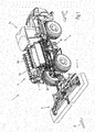
- a self-propelled mower 1 according to the FIGS. 1 and 1a comprises, for example, two fold-out front mowers 2, 3 each with a windrowing unit having a swath unit and at least two, in the illustrated transport position retracted side mowers 4, 5.
- the side mowers 4, 5 are each provided with a swath unit 6, 7.
- the windrow units 6, 7 comprise Schwadb suitable 8, 9, which are pivotally mounted on swing frames 10, 11 on the side mowers 4, 5.
- the side mower 4, 5 are rotatably mounted on telescopic arms 12, 13, so that they are in the transport position shown along the direction of travel F and are arranged in the working position as well as the illustrated front mowers 2, 3 transverse to the direction of travel.
- the self-propelled mower 1 moves in the working position in the mowing direction F. In the transport position, the mower 1 but moves in the opposite direction of travel A, so that during transport advantageously a cab 14 is arranged in front.
- the driver's cab 14 is arranged in the rear region, but can realize a good forward view of the front mowers 2, 3 through the laterally unfolded working units 4, 5, 6, 7.
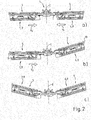
- FIG. 2 a second embodiment of a mower 1 is shown, which is designed as an attachment for a tractor or the like.
- the cultivation takes place for example with the standardized three-point hitch, so that the mower 1 according to FIG. 2 For example, at the rear of the tractor during transport in a raised transport position can be transported.
- FIG. 2a is the "normal" working position of the two side mowers 4, 5 and the downstream or associated swath units 6, 7 and Schwadb sections 8, 9 shown in normal working mode.
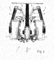
- FIG. 3 is the working position of the work units according to FIG. 2a shown schematically in plan view.
- the Schwadbs 8, 9 in the direction of travel F behind the side mowers 4, 5 are arranged so that they directly receive the mowed crop and transport in the central region of the longitudinal central surface E along the conveying directions V1 and V2.
- FIG. 2b shows a working position
- the right working unit or the right side mower 4 is raised together with the right Schwadband 8 and the right swath unit 6 in an intermediate position or in the so-called headland.
- this is for example the first transverse conveyor 6 and the left working unit or the left mower with the left Schwadband 9 and the left Schwadü 7 is in the mowing position.
- the right swath unit 6 according to the invention, the first transverse conveyor unit 6, 8, which has, for example, in this second working mode, a greater conveying speed than the second swath unit 7, 9 in the first working mode.
- the conveying speed of the first windrow unit 6 is slightly increased or accelerated at the moment of lifting or when the lifting is triggered according to an embodiment of the invention.
- FIG 2c is the position of the two side mowers 4, 5 and the windrow units 6, 7 shown, both units are in the so-called headland, that is, in the raised intermediate position.
- This increase in the conveying speed can also be realized temporarily.
- This deflated state can be detected in an advantageous manner and advantageously used to reset the conveying speed or to stop or end the transverse conveying.
- FIG. 5 is a further embodiment of the invention with a tractor 22 shown schematically, to which by means of a hitch 21, a mower M is attached or pulled by this.
- the mower M includes without further illustration in an advantageous manner two side mowers 4, 5, each with a Schwadband 8, 9 roughly comparable to that in FIG. 2 illustrated embodiment. That is also here by means of both Schwadbs 8, 9 transported to the center or to the longitudinal central surface E, the mowed crop. Likewise, a raised headland position or a raised transport position is provided.
- FIG. 5 an already deposited on the field to be machined 20 Querschwad 17 and an already stored and arranged in the viewing direction in front of the tractor or illustrated swath 19 available.
- This swath 19 was generated according to the invention. Accordingly, a swath end 18 of the swath 19 is spaced from the transverse swath 17 in an advantageous manner.
- the increased conveying speed made it possible to quickly empty the swathing strips 8, 9 in such a way that the crop was already deposited on the field 20 before the transverse swath 17.
- a sensor 15 is arranged on the roof of the tractor 22, which can detect an obstacle or crop such as a transverse swath 17 by means of a sensor array 16.
- this is an optical sensor 15 or a camera or like.
- the transverse swath 17 can be detected in an advantageous manner and the swathing can be controlled or controlled.
- the current travel speed and / or location coordinate of the tractor 22 it can be calculated when or where the transverse swath 17 is run over by the mower M.
- the conveying speed of the Schwadbs 8, 9, e.g. automatically increased and / or the mower M are spent in the headland position, so that the mower M and the Schwadbs 8, 9 emptied very quickly or before the transverse swath 17 and in particular raised.
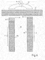
- FIG. 6 a field processing is shown in a transverse swath 17 with a mower 1 according to the invention.
- a field processing is shown in a transverse swath 17 with a mower 1 according to the invention.
- the detection / detection of the transverse swath 17 cf. FIG. 5
- the detection / detection of the transverse swath 17 cf. FIG. 5
- This second conveying speed according to the invention of the front mower 2, 3 and / or the side / rear mower 4, 5 can be carried out advantageously only briefly during the pivoting in / to the headland position or even during the entire time / duration in which the mower , 3, 4, 5 in the headland position or during a headland run 25 (see. FIG. 6 ) located.
- FIG. 6 an advantageous variant of Invention, wherein not only during the entire turn W transverse conveyor units 8, 9 or Schwadb sections 8, 9 according to the invention have the increased second conveying speed or maintained, but alternatively or in combination can according to the invention at the beginning of the mowing process to produce a swath 19b, the increased second conveying speed of the transverse conveyor units 8, 9 or Schwadb supports 8, 9 are provided.
- the increased conveying speed is achieved that a Schad rotating 23 or the swath 19b and a swath section 24 is arranged or stored particularly close / close to the transverse swath 17.
- a particularly advantageous swathing of all swath 18, 17 is possible.
Abstract
Description
Die Erfindung betrifft eine Erntemaschine, insbesondere eine Mähmaschine, nach dem Oberbegriff des Anspruchs 1.The invention relates to a harvesting machine, in particular a mowing machine, according to the preamble of
In der
Darüber hinaus sind beispielsweise aus der
Die Seitenmähwerke besitzen Schwadeinheiten, wobei mittels eines Schwadband abgemähtes Mähgut der Seitenmähwerke aufgenommen und zur Längsmittelebene des Fahrzeugs transportiert und im Normalbetriebsfall gemeinsam auf einem einzigen Schwad abgelegt wird.The side mower units have windrow units, which are mowed by a windrow mowing the side mowers and transported to the median longitudinal plane of the vehicle and stored in normal operation together on a single swath.
Die Frontmähwerke umfassen meistens einfachere Querförderer bzw. Leitscheiben oder dergleichen, die dafür Sorge tragen, dass im vorgenannten Fall mit einem einzigen Schwad das abgemähte Mähgut der Frontmähwerke zwischen den Laufrädern des Selbstfahrers abgelegt wird, auf den dann in einem "normalen" bzw. ersten Arbeitsmodus die Seitenmähwerke bzw. deren Querförderer zusätzlich abgemähtes Mähgut wie Gras oder dergleichen ablegen.The front mowers usually comprise simpler cross conveyors or guide disks or the like, which ensure that in the aforementioned case with a single swath the mowed crop of front mowers between the wheels of the self-driver is stored, then in a "normal" or first working mode the side mower or their cross conveyor additionally put down mowed crops such as grass or the like.
Darüber hinaus sind bereits in der Landtechnik derartige Mähmaschinen auch als Anbaugeräte für Traktoren oder dergleichen bekannt, die heckseitig mit der so genannten Dreipunktaufhängung am Traktor fixiert und angehoben werden können, um ohne Laufrad auszukommen. Häufig haben derartige heckseitige Mähgeräte ein entsprechend frontseitig angeordnetes einzelnes Mähwerk, das ebenfalls mittig längs der Längsmittelebene einen Schwad zwischen den Laufrädern des Traktors generiert. Das einzige heckseitige Mähwerk oder die beiden heckseitigen Mähwerke weisen wiederum jeweils einen Querförderer mit einem Transportband oder dergleichen auf, die entsprechend das Mähgut des/der Seitenmähwerke auf den bereits vorhandenen Mittelschwad des Frontmähwerks ablegen.In addition, such mowers are already known in agricultural technology as attachments for tractors or the like, which can be fixed to the rear of the so-called three-point hitch on the tractor and raised to get along without impeller. Frequently, such rear mowers have a correspondingly arranged on the front single mower, which also generates centrally along the longitudinal center plane a swath between the wheels of the tractor. The only rear-side mower or the two rear-side mowers in turn each have a cross conveyor with a conveyor belt or the like, put down the crop of / the side mower on the already existing central swath of the front mower.
Derartige im Einsatz verwendete Mähgeräte, ob paarweise oder einzeln verwendet, weisen jedoch Nachteile u.a. im so genannten Vorgewende auf, das heißt ein Anheben des/der Mähwerke bzw. Mähgeräte in eine Zwischenstellung, die zwischen der Arbeits- und der Transportstellung angeordnet ist. Beispielsweise bei einer Überfahrt über einen bereits vorhandenen, zur Fahrtrichtung quer ausgerichteten Schwad, der überfahren werden muss, kann es bei einem nachfolgenden Mähgang zu einem nachteiligen Queren bzw. Überlappen oder gar Verwerfen des bereits vorhandenen Schwades kommen. Vor dem Erreichen des Querschwades, jedoch während der Fahrt werden im Allgemeinen die Mähwerke bzw. das Mähwerk in die Zwischenstellung des Vorgewendes angehoben. Hierdurch kreuzen bzw. schneiden sich der gerade erzeugte neue Schwad mit dem bereits auf dem Feld liegenden Querschwad. Sich kreuzende Schwade sind jedoch von großem Nachteil, da diese beim nachfolgenden Aufnehmen mittels Pick-Up bzw. Ladewagen einerseits nicht sauber aufgenommen werden können und anderseits dies gewöhnlich zu Problemen wie einem Verstopfen der Ladeorgane führt.However, such mowing equipment used in use, whether used in pairs or individually, however, have disadvantages, among other things, in the so-called headland, that is lifting the mower or mowing equipment in an intermediate position, which is arranged between the working and the transport position. For example, in a crossing over an existing, transverse to the direction of travel swath, which must be run over, it may come at a subsequent mowing to a disadvantageous crossing or overlapping or even discarding the already existing swath. Before reaching the cross swath, but while driving generally the mower or the mower are raised to the intermediate position of the headland. As a result, the newly created swath cross or intersect with the already lying on the field Querschwad. However, crossing swaths are of great disadvantage, as they are in the subsequent picking by means of pick-up or loading wagons on the one hand can not be recorded clean and on the other hand this usually leads to problems such as clogging of the loading organs.
Zudem wird meistens unmittelbar nach dem Auslösen des Vorgewendevorganges ein sehr kleiner Radius des Fahrzeugs eingeschlagen, um möglichst effizient das Bearbeiten bzw. Mähen des Feldes fortzuführen. So muss hier häufig ein Wendemanöver realisiert werden, wobei der anschließende Bearbeitungsgang bzw. Mähgang in die entgegengesetzte Richtung bzw. um 180° gewendet weiter geführt werden muss. Hierzu sind sehr kleine Radien bzw. ein sofortiges, starkes Einschlagen der Lenkung notwendig.In addition, a very small radius of the vehicle is usually taken immediately after triggering the headland process in order to continue as efficiently as possible the editing or mowing of the field. So here often a turning maneuver must be realized, with the subsequent processing gear or mowing in the opposite direction or turned by 180 ° must be continued. For this purpose, very small radii or an immediate, strong steering of the steering are necessary.
Gerade bei einem derartigen starken Einschlagen der Lenkung, noch während die Arbeitseinheit bzw. das Mähwerk in die Vorgewendestellung übergeht, führt dies dazu, dass das Erntegut mit sehr kleinem Radius bzw. sehr enger Kurve abgelegt wird. Ein derart mit enger Kurve bzw. Radius abgelegter Schwad führt jedoch bei einem nachfolgenden Ernteschritt bzw. einer Aufnahme des Erntegutes mit einer Pick-Up-Maschine, vor allem mit einem Ladewagen, zu erheblichen Problemen. Letztere können oft keine derart engen Radien fahren, so dass der Schwad mehrfach angefahren werden muss.Especially with such a strong impact of the steering, while the work unit or the mower merges into the headland position, this leads to the crop with a very small radius or very tight curve is stored. However, such a swath deposited with a narrow curve or radius leads to considerable problems in a subsequent harvesting step or in picking up the crop with a pick-up machine, especially with a loader wagon. The latter often can not drive such narrow radii, so that the windrow must be approached several times.
Ein separater Arbeitsschritt mit dem Ladewagen oder gar mit einem separaten Schwader, (Hand-) Rechen oder dergleichen bedeutet jedoch einen zusätzlichen Arbeitsaufwand und zusätzliche Zeit bzw. Betriebsmittel, die benötigt werden, um das Erntegut möglichst vollständig aufzunehmen.A separate operation with the loader or even with a separate rake, (hand) rake or the like, however, means an additional workload and additional time or resources that are needed to absorb the crop as completely as possible.
Darüber hinaus werden vor allem bei Ladewagen, die relativ enge Radien fahren, die Grasnarbe beeinträchtig bzw. beschädigt, da deren Stützräder hierbei eine erhebliche Querbewegung durchführen müssen und dabei die Grasnarbe "abschaben".In addition, especially in self-propelled wagons that drive relatively narrow radii, the turf impaired or damaged, since their training wheels this case have to perform a significant lateral movement and thereby "scrape" the turf.
Aufgabe der vorliegenden Erfindung ist es dagegen, wenigstens teilweise die Nachteile des Stands der Technik zu beseitigen, insbesondere selbst in besonderen Situationen Aufwand und Zeit zum Zusammenlegen bzw. Abernten von abgemähtem Erntegut zu verringern.Object of the present invention, however, is to at least partially overcome the disadvantages of the prior art, in particular, even in special situations, effort and time to merge or harvesting abgeschähtem crop to reduce.
Diese Aufgabe wird, ausgehend von Erntemaschinen der einleitend genannten Art, durch die Merkmale des Anspruchs 1 gelöst. Durch die in den Unteransprüchen genannten Maßnahmen sind vorteilhafte Ausführungen und Weiterbildungen der Erfindung möglich.This object is achieved on the basis of harvesting machines of the aforementioned type by the features of
Dementsprechend zeichnet sich eine erfindungsgemäße Erntemaschine dadurch aus, dass im zweiten Arbeitsmodus die erste und/oder die zweite Querfördereinheit eine zweite Fördergeschwindigkeit aufweist, wobei die zweite Fördergeschwindigkeit größer als die erste Fördergeschwindigkeit ist.Accordingly, a harvesting machine according to the invention is characterized in that in the second working mode, the first and / or the second transverse conveyor unit has a second conveying speed, wherein the second conveying speed is greater than the first conveying speed.
Mit Hilfe dieser erfindungsgemäßen Maßnahme wird erreicht, dass die Schwadlegung im zweiten Arbeitsmodus bzw. im Vorgewende bzw. während dem Übergang von der Arbeitsstellung in die Zwischenstellung bzw. ins Vorgewende auch bei unterschiedlichsten Anforderungen bzw. Rahmenbedingungen oder Situationen in vorteilhafter Weise angepasst werden kann, wie z.B. beim Queren bzw. Kreuzen eines Querschwades bzw. eines bereits auf dem Feld vorhandenen/liegenden Schwades. So kann auch unter diesen Bedingungen ein eindeutig und klar abgegrenzter sowie nicht verworfener Schwad generiert werden, vor allem auch ohne dass der zu überfahrende bzw. zu kreuzende Querschwad bzw. der bereits auf dem Feld vorhandene/liegende Schwad beeinträchtigt wird. Dies führt dazu, dass auch unter derartigen besonderen Rahmenbedingungen bzw. Situation vor dem Abernten bzw. Aufladen des Erntegutes keine zusätzliche, separate Nachbearbeitung des/der Schwade bzw. kein zusätzlicher Aufwand für einen separaten Arbeitsschritt zumWith the help of this measure according to the invention it is achieved that the swathing in the second mode or in the headlands or during the transition from the working position to the intermediate position or headlands can be adapted in an advantageous manner even with very different requirements or conditions or situations, such as for example, when crossing or crossing a swath or a swath already present on the field. Thus, even under these conditions, a clearly defined and clearly demarcated and not discarded swath can be generated, especially without the cross swath to be crossed or to be crossed or the swath already present / lying on the field is impaired. This leads to the fact that even under such special conditions or situation prior to harvesting or loading of the crop no additional, separate post-processing of / the swath or no additional effort for a separate step to
Zusammenrechen bzw. Schwaden des Ernteguts notwendig wird.Collapse or swathing of the crop is necessary.
Durch die Vergrößerung der Fördergeschwindigkeit der (einen oder beider) Querfördereinheit wird nämlich erreicht, dass das quer geförderte Erntegut definiert bzw. in vorgegebener Weise auch unter besonderen Betriebsbedingungen bzw. in besonderen Arbeitssituationen bereits abgelegt werden kann, bevor der zu querende bzw. kreuzende Querschwad bzw. bereits auf dem Feld vorhandene/liegende Schwad erreicht/überfahren wird.By increasing the conveying speed of the (one or both) transverse conveyor unit, it is achieved that the transversely conveyed crop can be defined or stored in a predetermined manner even under special operating conditions or in special working situations, before the transverse swath to be crossed or crossed already reached / lying on the field swath is reached / run over.
Alternativ oder in Kombination zum Queren eines Querschwades ist die Erfindung in besonderem Maß auch dann von großem Vorteil, wenn z.B. unmittelbar nach dem Auslösen des Vorgewendes das Fahrzeug eine enge Kurve mit sehr kleinem Radius fährt. In diesem Fall wird gemäß der Erfindung das Erntegut derart schnell wegbefördert, dass dies möglichst bereits auf dem Feld liegt, bevor sich der Lenkausschlag nachteilig auf das Schwadlegen auswirkt. Auch in dieser Situation führt die Erfindung dazu, dass vor dem Abernten bzw. Aufladen des Erntegutes keine zusätzliche, separate Nachbearbeitung des/der Schwade bzw. kein zusätzlicher Aufwand für einen separaten Arbeitsschritt zum Zusammenrechen bzw. Schwaden des Ernteguts notwendig wird.Alternatively or in combination for traversing a swath, the invention is particularly advantageous even if, e.g. Immediately after the headland is triggered, the vehicle drives a tight bend with a very small radius. In this case, according to the invention, the crop is carried away so quickly that this is possible already in the field before the steering deflection adversely affects the swathing. Even in this situation, the invention leads to the fact that before harvesting or loading of the crop no additional, separate post-processing of / the swath or no additional effort for a separate step for collapsing or swathing of the crop is necessary.
So kann festgestellt werden, dass gemäß der Erfindung das Leerlaufen der einen oder der beiden bzw. mehreren Querfördereinheiten in vorteilhafter Weise entscheidend verkürzt wird, dass auch in besonderen Situationen Nachteile weitestgehend bzw. effektiv vermieden werden, ohne dass das Fahrzeug seine Fahrgeschwindigkeit verringern muss oder sogar anhalten und warten muss. Ein Verringern der Fahrgeschwindigkeit oder sogar ein Anhalten und Warten des Fahrzeugs bzw. der Querfördereinheiten wäre eine relativ ineffiziente Maßnahme bzw. würde zu einer Haufenbildung am Ende des Schwades oder möglicherweise zu einem Verstopfen führen.Thus, it can be stated that, according to the invention, the idling of one or both cross conveyor units is advantageously decisively shortened, so that disadvantages are substantially avoided even in special situations without the vehicle having to reduce its travel speed or even have to stop and wait. Reducing the vehicle speed or even stopping and maintaining the transversal unit (s) would be a relatively inefficient measure or would result in heap formation at the end of the swath or possibly clogging.
Bislang war beim Stand der Technik lediglich der erste Arbeitsmodus realisiert. Gemäß der Erfindung wird als Arbeitsmodus nicht das außer Betrieb Setzen einer der oder beider Querfördereinheiten betrachtet, sondern die erfindungsgemäßen Arbeitsmodi beziehen sich auf einen Betrieb, wobei eine Fördergeschwindigkeit vorhanden ist. Ein außer Betrieb setzen stellt gemäß der Erfindung keinen Arbeitsmodus, sondern einen Ruhemodus dar.So far, only the first working mode was realized in the prior art. According to the invention is as Working mode does not consider the decommissioning set one or both cross-conveyor units, but the working modes of the invention relate to an operation, wherein a conveying speed is present. A put out of service according to the invention is not a working mode, but a sleep mode.
Vorzugsweise verschwenkt im zweiten Arbeitsmodus die erste und/oder die zweite Querfördereinheit von der Arbeits- in eine Zwischenstellung bzw. in das so genannte Vorgewende bzw. ist in dieser Zwischenstellung angekommen/angeordnet. Das heißt, dass vor allem die Zeitdauer bzw. Phase des Verschwenkens bzw. Anhebens die erfindungsgemäße zweite, vergrößerte Fördergeschwindigkeit hierbei verwirklicht wird. Hiermit wird in vorteilhafter Weise ermöglicht, dass beispielsweise bei einem Anfahren eines bereits auf dem Feld liegenden und quer zur Fahrtrichtung ausgerichteten Schwades manuell durch den Fahrer oder automatisiert mittels vorteilhafter Sensorik oder dergleichen der zweite Arbeitsmodus ausgelöst bzw. veranlasst werden kann. Vorteilhafterweise ist das geförderte Erntegut bereits auf dem Feld abgelegt bevor der bereits vorhandene, auf dem Feld liegende Schwad erreicht bzw. überfahren wird, um diesen nicht zu verwerfen bzw. zu überdecken.Preferably, in the second mode of operation, the first and / or the second transverse conveyor unit pivots from the working position into an intermediate position or into the so-called headland or has arrived / arranged in this intermediate position. This means that above all the period of time or phase of pivoting or lifting the second, increased conveying speed according to the invention is realized here. This makes it possible in an advantageous manner that, for example, when starting a already lying in the field and aligned transversely to the direction of swath manually by the driver or automatically by means of advantageous sensors or the like, the second mode can be triggered or initiated. Advantageously, the subsidized crop is already stored in the field before the already existing, lying in the field swath is reached or run over in order not to discard this or to cover.
In einer vorteilhaften Variante de Erfindung ist wenigstens eine Starteinheit zum Starten und/oder Auslösen des zweiten Arbeitsmodus und/oder des Verschwenkens der ersten und/oder zweiten Querfördereinheit vorgesehen. Einerseits kann das Starten der Vergrößerung gemäß der Erfindung manuell und/oder andererseits automatisiert bzw. von der Starteinheit und/oder einer Kontrolleinheit der Startereinheit nahezu selbsttätig gesteuert eingestellt bzw. verändert werden. Beispielsweise kann als Auslöser bzw. Initiator für das Auslösen auch das Anheben eines Frontmähwerkes vorgesehen werden. Der zweite Arbeitsmodus wird dann in diesem vorteilhaften Fall automatisch ausgelöst. Hierbei ist dann die Aktivierungs- bzw. Betätigungseinheit des Frontmähwerks als Starteinheit gemäß der Erfindung ausgebildet.In an advantageous variant of the invention, at least one starting unit is provided for starting and / or triggering the second operating mode and / or the pivoting of the first and / or second transverse conveying unit. On the one hand, the starting of the magnification according to the invention can be manually and / or on the other hand automated or almost automatically controlled or changed by the starting unit and / or a control unit of the starter unit. For example, can be provided as a trigger or initiator for triggering the lifting of a front mower. The second working mode is then automatically triggered in this advantageous case. In this case, then the activation or actuation unit of the front mower is designed as a start unit according to the invention.
In besonderen Weiterbildungen der Erfindung umfasst die Starteinheit z.B. wenigstens eine Sensoreinheit zum Erfassen eines Hindernisses und/oder von Erntegut und/oder wenigstens einer Ortskoordinate der Querfördereinheit und/oder wenigstens einer Ortskoordinate der Erntemaschine. Beispielsweise ist ein Hindernis ein Baum, eine Hecke, ein Zaun, ein Bauwerk oder dergleichen. Als Erntegut kann hierbei durchaus noch nicht gemähtes und/oder nicht abgeerntetes wie auf dem Feld liegendes Erntegut, z.B. ein vorhandener Querschwad oder dergleichen, darstellen. Ein vorteilhafter Sensor bzw. Sensorik kann unter anderem als Ultraschall- und/oder Intrarot- und/oder Radar- und/oder Laser- und/oder Echolot- und/oder Optik-Sensor/-Sensorik und/oder als Bildaufnahmeeinheit wie ein Fotoapparat oder eine Videokamera ausgebildet werden. So ist denkbar, einen Vergleich erfasster Informationen bzw. Bilder mit hinterlegten Informationen bzw. Daten durchzuführen, ob ein Hindernis, insbesondere ein Querschwad, in Fahrtrichtung angeordnet bzw. vorhanden ist. Mit entsprechender Auswertung des Vergleichs kann dann eine vorteilhafte Veränderung bzw. Vergrößerung der Fördergeschwindigkeit gemäß der Erfindung realisiert werden.In particular embodiments of the invention, the starting unit comprises e.g. at least one sensor unit for detecting an obstacle and / or crop and / or at least one location coordinate of the cross conveyor unit and / or at least one location coordinate of the harvesting machine. For example, an obstacle is a tree, a hedge, a fence, a structure or the like. The crop may well be uncut and / or unharvested, such as on-field crop, e.g. an existing transverse swath or the like. An advantageous sensor or sensor system may, inter alia, as ultrasound and / or infrared and / or radar and / or laser and / or echosounder and / or optical sensor / sensor and / or as an image recording unit such as a camera or a video camera can be formed. Thus, it is conceivable to carry out a comparison of acquired information or images with stored information or data as to whether an obstacle, in particular a transverse swath, is arranged or provided in the direction of travel. With appropriate evaluation of the comparison, an advantageous change or increase in the conveying speed can then be realized according to the invention.
In Bezug zur Erfassung einer Ortskoordinate kann in vorteilhafter Weise ein GPS-System bzw. GPS-Signale oder dergleichen verwendet werden, das beispielsweise abgespeicherte Informationen bzgl. Hindernisse oder dergleichen umfasst und/oder Informationen bzgl. unmittelbar zuvor generierte bzw. auf dem Feld abgelegtes Erntegut bzw. Schade aufweist. Diese gespeicherten Informationen können dann in vorteilhafter Weise für die Erkennung bzw. Steuerung der Fördergeschwindigkeit gemäß der Erfindung verwendet werden. Das bedeutet zum Beispiel, dass bereits beim Annähern an ein Hindernis oder ein Querschwad etc. die Fördergeschwindigkeit gemäß der Erfindung allmählich und/oder stufenweise vergrößert wird. Beispielsweise kann eine Kontrolleinheit mittels Fahrgeschwindigkeitsinformationen sowie Abstands- und/oder Ortskoordinateninformationen die Zeitdauer und/oder die Kreuzung bzw. das Überfahren des Querschwades oder dergleichen berechnen und dementsprechend die Änderung bzw. der Verlauf der Vergrößerung der Fördergeschwindigkeit steuern bzw. anpassen. So kann die Fördergeschwindigkeit in dem Maß erhöht werden, wie sich der Abstand zum Hindernis bzw. Erntegut/Querschwad verringert.In relation to the detection of a location coordinate, a GPS system or GPS signals or the like can advantageously be used, which comprises, for example, stored information regarding obstacles or the like and / or information relating to crop material generated immediately before or deposited on the field or a pity. This stored information can then be used advantageously for the detection or control of the conveying speed according to the invention. This means, for example, that already when approaching an obstacle or a cross swath, etc., the conveying speed is gradually and / or gradually increased according to the invention. For example, a control unit by means of vehicle speed information as well as distance and / or location coordinate information to calculate the time and / or crossing or crossing the crosswalk or the like, and accordingly the change or the course control or adjust the increase in the conveying speed. Thus, the conveying speed can be increased to the extent that reduces the distance to the obstacle or crop / Querschwad.
Auch kann die Fahrgeschwindigkeit der Erntemaschine beim Annähern an ein Hindernis bzw. an Erntegut wie ein Querschwad in vorteilhafter Weise angepasst bzw. entsprechend verkleinert werden.Also, the driving speed of the harvester when approaching an obstacle or crop such as a Querschwad be adapted or reduced accordingly.
In einer vorteilhaften Ausführungsform der Erfindung weist die Querfördereinheit/en wenigsten einen Sensor zum Erfassen des zu fördernden Erntegutes bzw. Erntegutstromes auf. Dieser kann als Vorhanden/Nicht-Vorhanden-Detektion ausgeführt werden oder auch differenzierte Informationen erzeugen. Zum Beispiel kann ein optischer, IR- oder Ultraschall-Sensor die Menge erfassen und hiervon abhängig die Fördergeschwindigkeit verändern bzw. gemäß der Erfindung vergrößern. So wird die Menge abnehmen, wenn kein Erntegut aufgenommen bzw. abgemäht wird und dies kann bedeuten, dass ein Querschwad angefahren wird. Dementsprechend kann der zweite Arbeitsmodus veranlasst und/oder die größere bzw. zweite Fördergeschwindigkeit realisiert werden.In an advantageous embodiment of the invention, the cross conveyor unit / s least one sensor for detecting the crop to be conveyed or Erntegutstromes on. This can be performed as existing / non-existent detection or also produce differentiated information. For example, an optical, IR or ultrasonic sensor can detect the quantity and, depending thereon, change the conveying speed or increase it according to the invention. So the amount will decrease if no crop is picked up or mowed and this may mean that a Querschwad is approached. Accordingly, the second working mode can be initiated and / or the larger or second conveying speed can be realized.
Vorteilhafterweise ist die zweite Fördergeschwindigkeit um wenigstens 3 % oder wenigstens 10 % oder wenigstens 15 % größer als die erste Fördergeschwindigkeit. Es hat sich in ersten Versuchen gezeigt, dass etwa zwischen 3 % und ca. 20 % Vergrößerung der zweiten Fördergeschwindigkeit gegenüber der ersten Fördergeschwindigkeit eine vorteilhafte Anpassung auch an besondere Situationen bzw. Rahmenbedingungen realisierbar ist.Advantageously, the second conveying speed is at least 3% or at least 10% or at least 15% greater than the first conveying speed. It has been shown in first experiments that approximately between 3% and about 20% increase in the second conveying speed relative to the first conveying speed, an advantageous adaptation to particular situations or conditions is feasible.
Vorzugsweise ist die zweite Fördergeschwindigkeit im Wesentlichen ca. 70% oder ca. 80% oder ca. 90% der maximalen Fördergeschwindigkeit. Die erste bzw. "normale" Fördergeschwindigkeit wird vielfach z.B. im Wesentlichen auf 40% bis 50% der maximalen Fördergeschwindigkeit eingestellt, so dass gemäß der Erfindung etwa fast eine Verdoppelung von der ersten in die zweite Fördergeschwindigkeit umgesetzt wird. Diese deutliche Beschleunigung bzw. Vergrößerung ermöglicht eine besonders vorteilhafte Schwadablage.Preferably, the second conveying speed is substantially about 70% or about 80% or about 90% of the maximum conveying speed. The first or "normal" conveying speed is frequently set, for example, essentially to 40% to 50% of the maximum conveying speed, so that according to the invention approximately a doubling of the first is converted to the second conveying speed. This significant acceleration or expansion allows a particularly advantageous swathing.
In einer bevorzugten Variante der Erfindung ist wenigstens eine Einstelleinheit zum Einstellen der erfindungsgemäßen Vergrößerung und/oder anschließenden Zurückstellung bzw. Verkleinerung der Fördergeschwindigkeiten vorgesehen. Einerseits kann die Einstellung des Maßes der Vergrößerung und/oder der Verkleinerung manuell und/oder andererseits automatisiert bzw. von einer Kontrolleinheit nahezu selbsttätig gesteuert eingestellt bzw. verändert werden.In a preferred variant of the invention, at least one adjusting unit is provided for adjusting the enlargement according to the invention and / or subsequent retraction or reduction of the conveying speeds. On the one hand, the setting of the degree of enlargement and / or the reduction can be manually and / or otherwise automated or adjusted by a control unit almost automatically controlled or changed.
Vorzugsweise ist die Starteinheit und/oder die Einstelleinheit in einer Fahrerkabine und/oder an einem Arbeitsplatz des Fahrers angeordnet. Hierdurch kann der Fahrer in vorteilhafter Weise vor oder während der Arbeit die Auslösung des zweiten Arbeitsmodus und/oder eine Änderung der Einstellung vornehmen, beispielsweise eine Änderung des Maßes der Vergrößerung und/oder der Verkleinerung. Beispielsweise kann dies stufenlos oder zum Beispiel in drei Stufen erfolgen, wie zum Beispiel eine Änderung der Fördergeschwindigkeit in der ersten Stufe um ca. 5 % und in der zweiten Stufe um ca. 10 % und in der dritten Stufe um ca. 20 % und/oder es kann pauschal eine Vergrößerung der Fördergeschwindigkeit auf z.B. im Wesentlichen 70% oder 80% oder 90% der maximalen Fördergeschwindigkeit vorgegeben bzw. eingestellt werden. Vorteilhafterweise erfolgt eine Zurückstellung bzw. Verringerung/Verkleinerung der Fördergeschwindigkeit nahezu automatisiert durch das Verstellen der Querfördereinheit/en in die Arbeitstellung. Jedoch ist durchaus eine manuelle Zurückstellung in die erste Fördergeschwindigkeit realisierbar.The starting unit and / or the setting unit are preferably arranged in a driver's cab and / or at a driver's workstation. In this way, the driver can advantageously make the triggering of the second operating mode and / or a change in the setting before or during the work, for example a change in the degree of enlargement and / or the reduction. For example, this can be done continuously or for example in three stages, such as a change in the conveying speed in the first stage by about 5% and in the second stage by about 10% and in the third stage by about 20% and / or it can be an overall increase in the conveying speed on eg Essentially 70% or 80% or 90% of the maximum conveying speed are set or adjusted. Advantageously, a retraction or reduction / reduction of the conveying speed takes place almost automatically by adjusting the transverse conveyor unit / s in the working position. However, a manual reset in the first conveying speed is quite feasible.
Vorzugsweise ist wenigstens eine Arbeitseinheit vorgesehen, die eine der Querfördereinheiten und ein das Erntegut mähende Mähwerk umfasst. Die Querfördereinheit ist dem Mähwerk nachgeordnet, das heiß in Fahrtrichtung betrachtet hinter dem Mähwerk zur Aufnahme des gerade abgemähten Erntegutes ausgebildet.Preferably, at least one working unit is provided, which comprises one of the transverse conveyor units and a mower mowing the crop. The transverse conveyor unit is arranged downstream of the mower, which, viewed hot in the direction of travel behind the mower for receiving the just mowed crop educated.
Beispielsweise kann die Arbeitseinheit derart ausgebildet werden, dass die Querfördereinheit, insbesondere ein Bandschwader, in einer besonderen Betriebsweise derart vertikal verstellt wird, um ein Mähen ohne Querförderung zu realisieren.For example, the working unit can be designed such that the transverse conveyor unit, in particular a belt swather, is adjusted vertically in a particular mode of operation in order to realize a mowing without transverse conveying.
Vorzugsweise ist die Erntemaschine gemäß der Erfindung als Anbaugerät zum Anbau an ein Trägerfahrzeug ausgebildet. Hierbei kann es sich einerseits um ein gezogenes Arbeitsgerät handeln, das ein eigenes Laufrad/Fahrwerk aufweist. Das Laufrad kann beispielsweise sowohl für den Transport auf der Straße als auch zum Fahren auf dem zu bearbeitenden Feld verwendet werden. Alternativ kann auch ein Anbaugerät vorgesehen werden, dass beim Transport beispielsweise mittels der üblichen Dreipunktanhängung angehoben wird. Bei dieser Variante der Erfindung benötigt die Erntemaschine gemäß der Erfindung kein eigenes Laufrad, zumindest für den Transport.Preferably, the harvesting machine according to the invention is designed as an attachment for attachment to a carrier vehicle. On the one hand, this may be a towed implement that has its own running wheel / chassis. For example, the impeller may be used both for road transport and for driving on the field to be worked. Alternatively, an attachment may be provided that is raised during transport, for example by means of the usual three-point hitch. In this variant of the invention, the harvesting machine according to the invention does not need its own impeller, at least for transport.
Alternativ kann die erfindungsgemäße Erntemaschine auch als Selbstfahrer ausgebildet werden, das heißt diese weist einen eigenen Antriebsmotor sowie Antriebsräder auf.Alternatively, the harvesting machine according to the invention can also be designed as a self-propelled, that is, this has its own drive motor and drive wheels.
Generell kann die erfindungsgemäße Erntemaschine nicht nur als Mähmaschine, sondern auch als andere, in der Landwirtschaft in der Ernte einsetzbare Arbeitsmaschine ausgebildet werden. Beispielsweise sind auch Bandschwader ohne Mähwerk denkbar. So können durchaus auch Schwader, insbesondere auch Kreiselschwader mit mehreren Kreiselrechen, eine erfindungsgemäße Veränderung der Fördergeschwindigkeiten der entsprechenden (rechtsseitigen oder linksseitigen) Querfördereinheiten bzw. Kreisel aufweisen.In general, the harvesting machine according to the invention can be designed not only as a mower, but also as other, usable in agriculture in the harvest work machine. For example, also band swather without mower are conceivable. Thus, swathers, in particular rotary windrowers with several rotary rakes, can also have a change in the conveying speeds of the corresponding (right-hand or left-hand) transverse conveyor units or rotors according to the invention.
Ein Ausführungsbeispiel ist in der Zeichnung dargestellt und wird anhand der Figuren nachfolgend näher erläutert.An embodiment is shown in the drawing and will be explained in more detail with reference to FIGS.
Im Einzelnen zeigen:
Figur 1- eine selbstfahrende Mähmaschine in perspektivischer, schematischer Seitenansicht mit vier erfindungsgemäßen Mähwerken mit zugeordneten Schwadeinheiten in Transportstellung,
- Figur 1a
- eine selbstfahrende Mähmaschine gemäß
Figur 1 in der Frontansicht, - Figur 2a bis 2c
- eine schematische Darstellung eines getragenen Anbaugeräts mit zwei erfindungsgemäßen Mähwerken und diesen zugeordneten Schwadeinheiten in drei unterschiedlichen Arbeitsstellungen,
Figur 3- eine schematische Draufsicht auf das
Anbaugerät gemäß Figur 2 in Arbeitsstellung, Figur 4- eine schematische Draufsicht der Mähmaschine gemäß
Figur 3 in der Transportstellung, Figur 5- eine schematische Seitenansicht einer weiteren Mähmaschine in Arbeitsstellung vor dem Erreichen eines bereits auf dem Feld liegenden Querschwades und
Figur 6- eine schematische Darstellung einer Feldbearbeitung bei einem Querschwad mit einer Mähmaschine gemäß der Erfindung.
- FIG. 1
- a self-propelled mower in a perspective, schematic side view with four mowers according to the invention with associated windrow units in the transport position,
- FIG. 1a
- a self-propelled mower according to
FIG. 1 in the front view, - FIGS. 2a to 2c
- a schematic representation of a supported attachment with two mowers according to the invention and associated swath units in three different working positions,
- FIG. 3
- a schematic plan view of the attachment according to
FIG. 2 in working position, - FIG. 4
- a schematic plan view of the mower according to
FIG. 3 in the transport position, - FIG. 5
- a schematic side view of another mower in working position before reaching an already lying on the field cross swath and
- FIG. 6
- a schematic representation of a field processing in a Querschwad with a mower according to the invention.
Eine selbstfahrende Mähmaschine 1 gemäß den
Die Seitenmähwerke 4, 5 sind an Teleskopauslegern 12, 13 drehbar befestigt, so dass sie in der dargestellten Transportposition längs zur Fahrtrichtung F liegen und in der Arbeitsstellung ebenso wie die dargestellten Frontmähwerke 2, 3 quer zur Fahrtrichtung angeordnet werden.The
Die selbstfahrende Mähmaschine 1 fährt in Arbeitsstellung in die Mähfahrtrichtung F. In der Transportstellung fährt die Mähmaschine 1 jedoch in die entgegengesetzte Transportfahrtrichtung A, so dass während des Transportes in vorteilhafter Weise eine Fahrkabine 14 vorne angeordnet ist. Während des Mähbetriebs ist die Fahrerkabine 14 dagegen im hinteren Bereich angeordnet, kann jedoch durch die seitlich ausgeklappten Arbeitseinheiten 4, 5, 6, 7 eine gute Sicht nach vorne zu den Frontmähwerken 2, 3 realisieren.The self-propelled
In
In
In
Vorzugsweise wird die Fördergeschwindigkeit der ersten Schwadeinheit 6 im Moment des Anhebens bzw. beim Auslösen des Anhubs gemäß einer Ausführungsform der Erfindung etwas vergrößert bzw. beschleunigt.Preferably, the conveying speed of the
In
Gemäß der Erfindung weisen die beiden Schwadeinheiten 6, 7 während und/oder nach dem Verstellen von der Arbeitsstellung in die Vorgewendestellung gemäß
In
Darüber hinaus ist in
Bei der dargestellten Variante ist eine Sensorik 15 auf dem Dach des Traktors 22 angeordnet, die mittels eines Sensorfeldes 16 ein Hindernis bzw. Erntegut wie einen Querschwad 17 detektieren kann. Beispielsweise handelt es sich hier um eine optische Sensorik 15 bzw. um eine Kamera oder dergleichen. Mit dieser Sensorik 15 kann in vorteilhafter Weise der Querschwad 17 erfasst und die Schwadablage gesteuert bzw. kontrolliert werden. So kann ggf. mit Hilfe der aktuellen Fahrgeschwindigkeit und/oder Ortskoordinate des Traktors 22 berechnet werden, wann bzw. wo der Querschwad 17 vom Mähwerk M überfahren wird.In the illustrated variant, a
Dementsprechend kann nach ggf. detektierter Beendigung des Mähens von stehendem Erntegut mittels vorteilhafter weiterer Sensorik die Fördergeschwindigkeit der Schwadbänder 8, 9 z.B. automatisiert erhöht und/oder das Mähwerk M in die Vorgewendestellung verbracht werden, so dass das Mähwerk M bzw. die Schwadbänder 8, 9 sehr schnell bzw. vor dem Querschwad 17 entleert und insbesondere angehoben werden.Accordingly, after possibly detected completion of the mowing of stationary crop by means of advantageous further sensors, the conveying speed of the
In
Darüber hinaus ist in
- 11
- Mähmaschinemower
- 22
- FrontmähwerkFrontmähwerk
- 33
- FrontmähwerkFrontmähwerk
- 44
- Seitenmähwerkside mower
- 55
- Seitenmähwerkside mower
- 66
- Schwadeinheitswathing
- 77
- Schwadeinheitswathing
- 88th
- Schwadbandwindrowing
- 99
- Schwadbandwindrowing
- 1010
- Schwenkrahmenswing frame
- 1111
- Schwenkrahmenswing frame
- 1212
- Teleskopauslegertelescopic boom
- 1313
- Teleskopauslegertelescopic boom
- 1414
- Kabinecabin
- 1515
- Sensoriksensors
- 1616
- Sensorfeldsensor field
- 1717
- QuerschwadQuerschwad
- 1818
- Schwadendethe swath
- 1919
- Schwadwindrow
- 2020
- Feldfield
- 2121
- Anhängunghitch
- 2222
- Traktortractor
- 2323
- SchwadanfangSchwadanfang
- 2424
- SchwadabschnittSchwadabschnitt
- 2525
- VorgewendefahrtHeadland trip
- AA
- TransportfahrtrichtungTransport direction
- DD
- Detektiondetection
- Ee
- LängsmittelflächeLongitudinal central area
- FF
- MähfahrtrichtungMähfahrtrichtung
- MM
- MähwerkMower
- VV
- Förderrichtungconveying direction
- WW
- Wendeturn
Claims (10)
Applications Claiming Priority (2)
| Application Number | Priority Date | Filing Date | Title |
|---|---|---|---|
| DE102011100348 | 2011-05-03 | ||
| DE201210004045 DE102012004045A1 (en) | 2011-05-03 | 2012-03-02 | "Harvesting machine with at least one cross conveyor" |
Publications (1)
| Publication Number | Publication Date |
|---|---|
| EP2520155A1 true EP2520155A1 (en) | 2012-11-07 |
Family
ID=46177226
Family Applications (1)
| Application Number | Title | Priority Date | Filing Date |
|---|---|---|---|
| EP12166693A Ceased EP2520155A1 (en) | 2011-05-03 | 2012-05-03 | Harvesting machine with at least one cross conveyor |
Country Status (2)
| Country | Link |
|---|---|
| EP (1) | EP2520155A1 (en) |
| DE (1) | DE102012004045A1 (en) |
Cited By (6)
| Publication number | Priority date | Publication date | Assignee | Title |
|---|---|---|---|---|
| EP3581016A1 (en) * | 2018-06-15 | 2019-12-18 | CNH Industrial Belgium N.V. | Rake rotor height control |
| EP3804497A1 (en) | 2019-10-11 | 2021-04-14 | PÖTTINGER Landtechnik GmbH | Windrow and method for producing such a windrow |
| US20210282319A1 (en) * | 2020-03-11 | 2021-09-16 | Agco International Gmbh | Agricultural apparatus |
| US20210282317A1 (en) * | 2020-03-11 | 2021-09-16 | Agco International Gmbh | Agricultural apparatus comprising height sensors, and related methods |
| US20210352848A1 (en) * | 2020-05-18 | 2021-11-18 | Claas Saulgau Gmbh | Merger Control Device and Merger |
| US11432464B2 (en) | 2017-06-26 | 2022-09-06 | Kubota Corporation | Harvesting machine with crop detection and harvesting width detection |
Citations (4)
| Publication number | Priority date | Publication date | Assignee | Title |
|---|---|---|---|---|
| EP1068791A1 (en) | 1999-07-10 | 2001-01-17 | Deere & Company | Self-propelled mower with conveyors |
| EP1155609B1 (en) | 2000-05-16 | 2004-11-17 | Deere & Company | Swathing device |
| DE102005051544A1 (en) | 2005-10-26 | 2007-05-03 | Claas Saulgau Gmbh | Mower with a swath |
| US20100223896A1 (en) * | 2009-03-06 | 2010-09-09 | Eick Bronson C | Agricultural Harvester With Accelerated Draper Belt Unload |
-
2012
- 2012-03-02 DE DE201210004045 patent/DE102012004045A1/en not_active Withdrawn
- 2012-05-03 EP EP12166693A patent/EP2520155A1/en not_active Ceased
Patent Citations (4)
| Publication number | Priority date | Publication date | Assignee | Title |
|---|---|---|---|---|
| EP1068791A1 (en) | 1999-07-10 | 2001-01-17 | Deere & Company | Self-propelled mower with conveyors |
| EP1155609B1 (en) | 2000-05-16 | 2004-11-17 | Deere & Company | Swathing device |
| DE102005051544A1 (en) | 2005-10-26 | 2007-05-03 | Claas Saulgau Gmbh | Mower with a swath |
| US20100223896A1 (en) * | 2009-03-06 | 2010-09-09 | Eick Bronson C | Agricultural Harvester With Accelerated Draper Belt Unload |
Cited By (10)
| Publication number | Priority date | Publication date | Assignee | Title |
|---|---|---|---|---|
| US11432464B2 (en) | 2017-06-26 | 2022-09-06 | Kubota Corporation | Harvesting machine with crop detection and harvesting width detection |
| EP3581016A1 (en) * | 2018-06-15 | 2019-12-18 | CNH Industrial Belgium N.V. | Rake rotor height control |
| BE1026368B1 (en) * | 2018-06-15 | 2020-01-20 | Cnh Ind Belgium Nv | HEIGHT ADJUSTMENT OF A RAKE ROTOR |
| US11889778B2 (en) | 2018-06-15 | 2024-02-06 | Cnh Industrial America Llc | Rake rotor height control |
| EP3804497A1 (en) | 2019-10-11 | 2021-04-14 | PÖTTINGER Landtechnik GmbH | Windrow and method for producing such a windrow |
| DE102019127447A1 (en) * | 2019-10-11 | 2021-04-15 | Pöttinger Landtechnik Gmbh | Rake and methods of controlling such a rake |
| US20210282319A1 (en) * | 2020-03-11 | 2021-09-16 | Agco International Gmbh | Agricultural apparatus |
| US20210282317A1 (en) * | 2020-03-11 | 2021-09-16 | Agco International Gmbh | Agricultural apparatus comprising height sensors, and related methods |
| US11882790B2 (en) * | 2020-03-11 | 2024-01-30 | Agco International Gmbh | Agricultural apparatus and methods of operating an agricultural apparatus |
| US20210352848A1 (en) * | 2020-05-18 | 2021-11-18 | Claas Saulgau Gmbh | Merger Control Device and Merger |
Also Published As
| Publication number | Publication date |
|---|---|
| DE102012004045A1 (en) | 2012-12-06 |
Similar Documents
| Publication | Publication Date | Title |
|---|---|---|
| EP3593620B1 (en) | Harvesting system | |
| BE1025479B1 (en) | Agricultural harvester for processing and conveying crop with a sensor assembly for detecting unwanted hazardous substances and ingredients in the crop | |
| EP1731983B1 (en) | Agricultural work machine comprising a discharging device and a collision sensor | |
| EP2266383B1 (en) | Control assembly for controlling the transfer of harvested agricultural goods from a harvester to a transport vehicle with a loading container | |
| EP2100495B2 (en) | Agricultural harvester with a transfer device | |
| EP2510775B1 (en) | Method and system for controlling the transfer of harvested goods | |
| EP2301323B1 (en) | Device for monitoring whether a harvested goods receptacle is functioning correctly | |
| EP2574229B1 (en) | Self-propelled agricultural harvesting machine with a harvesting attachment swivel-mounted on a vertical axis | |
| DE102012211001A1 (en) | Arrangement for controlling adjustable harvest conveying element of output device of harvester, has controller to bring harvest conveying element from loading into idle position, when overloading process is not possible | |
| DE102008015277A1 (en) | Method and device for steering a second agricultural machine, which is steerable over a field relative to a first agricultural machine | |
| EP2520155A1 (en) | Harvesting machine with at least one cross conveyor | |
| EP1281312B1 (en) | Device with a pick-up, a conveyor and connecting means with a vehicle | |
| DE102009041646A1 (en) | Self-propelled agricultural machine has receiving tool for receiving harvest from field, contactless proximity sensor, and autopilot unit for guiding machine depending on detected crop edge | |
| EP1796454B1 (en) | Harvesting equipment, in particular harvesting attachment for agricultural harvesting machines used to gather and transport cereals | |
| EP3837961B1 (en) | Combination of a towing vehicle and a device | |
| DE102014105820A1 (en) | Combination of a towing vehicle and a harvester pulled by it | |
| DE102016202628A1 (en) | Sensor arrangement for monitoring the function of a header | |
| EP2520156B1 (en) | Harvesting machine with at least two cross conveyors | |
| EP3791707A1 (en) | Device for processing plant material near the ground and method for processing plant material near the ground | |
| DE102011084288A1 (en) | Self-propelled harvesting machine has chassis, to which front wheel or crawler traveling gear and oscillating suspended rear axle are mounted with steerable, rear wheels | |
| BE1026568B1 (en) | Self-propelled harvester with a loading device | |
| DE102019207984A1 (en) | Harvesting machine with a sensor for monitoring the stubble | |
| DE102019005662A1 (en) | Discharge spout for a forage harvester | |
| DE102008040217B4 (en) | Between an operating position and a compact transport position adjustable header | |
| EP3400778B1 (en) | Method for operating a self-propelled harvester |
Legal Events
| Date | Code | Title | Description |
|---|---|---|---|
| PUAI | Public reference made under article 153(3) epc to a published international application that has entered the european phase |
Free format text: ORIGINAL CODE: 0009012 |
|
| AK | Designated contracting states |
Kind code of ref document: A1 Designated state(s): AL AT BE BG CH CY CZ DE DK EE ES FI FR GB GR HR HU IE IS IT LI LT LU LV MC MK MT NL NO PL PT RO RS SE SI SK SM TR |
|
| AX | Request for extension of the european patent |
Extension state: BA ME |
|
| 17P | Request for examination filed |
Effective date: 20130507 |
|
| 17Q | First examination report despatched |
Effective date: 20160308 |
|
| STAA | Information on the status of an ep patent application or granted ep patent |
Free format text: STATUS: THE APPLICATION HAS BEEN REFUSED |
|
| 18R | Application refused |
Effective date: 20170708 |