EP1630574B1 - Device mounted on agricultural machines for contactless mapping of ground surface contours - Google Patents
Device mounted on agricultural machines for contactless mapping of ground surface contours Download PDFInfo
- Publication number
- EP1630574B1 EP1630574B1 EP05025272.5A EP05025272A EP1630574B1 EP 1630574 B1 EP1630574 B1 EP 1630574B1 EP 05025272 A EP05025272 A EP 05025272A EP 1630574 B1 EP1630574 B1 EP 1630574B1
- Authority
- EP
- European Patent Office
- Prior art keywords
- contour
- scanning
- agricultural machine
- laser
- ground
- Prior art date
- Legal status (The legal status is an assumption and is not a legal conclusion. Google has not performed a legal analysis and makes no representation as to the accuracy of the status listed.)
- Expired - Lifetime
Links
Images


Classifications
-
- A—HUMAN NECESSITIES
- A01—AGRICULTURE; FORESTRY; ANIMAL HUSBANDRY; HUNTING; TRAPPING; FISHING
- A01B—SOIL WORKING IN AGRICULTURE OR FORESTRY; PARTS, DETAILS, OR ACCESSORIES OF AGRICULTURAL MACHINES OR IMPLEMENTS, IN GENERAL
- A01B69/00—Steering of agricultural machines or implements; Guiding agricultural machines or implements on a desired track
- A01B69/007—Steering or guiding of agricultural vehicles, e.g. steering of the tractor to keep the plough in the furrow
- A01B69/008—Steering or guiding of agricultural vehicles, e.g. steering of the tractor to keep the plough in the furrow automatic
-
- A—HUMAN NECESSITIES
- A01—AGRICULTURE; FORESTRY; ANIMAL HUSBANDRY; HUNTING; TRAPPING; FISHING
- A01B—SOIL WORKING IN AGRICULTURE OR FORESTRY; PARTS, DETAILS, OR ACCESSORIES OF AGRICULTURAL MACHINES OR IMPLEMENTS, IN GENERAL
- A01B69/00—Steering of agricultural machines or implements; Guiding agricultural machines or implements on a desired track
- A01B69/001—Steering by means of optical assistance, e.g. television cameras
-
- G—PHYSICS
- G01—MEASURING; TESTING
- G01S—RADIO DIRECTION-FINDING; RADIO NAVIGATION; DETERMINING DISTANCE OR VELOCITY BY USE OF RADIO WAVES; LOCATING OR PRESENCE-DETECTING BY USE OF THE REFLECTION OR RERADIATION OF RADIO WAVES; ANALOGOUS ARRANGEMENTS USING OTHER WAVES
- G01S17/00—Systems using the reflection or reradiation of electromagnetic waves other than radio waves, e.g. lidar systems
- G01S17/88—Lidar systems specially adapted for specific applications
- G01S17/89—Lidar systems specially adapted for specific applications for mapping or imaging
-
- G—PHYSICS
- G01—MEASURING; TESTING
- G01S—RADIO DIRECTION-FINDING; RADIO NAVIGATION; DETERMINING DISTANCE OR VELOCITY BY USE OF RADIO WAVES; LOCATING OR PRESENCE-DETECTING BY USE OF THE REFLECTION OR RERADIATION OF RADIO WAVES; ANALOGOUS ARRANGEMENTS USING OTHER WAVES
- G01S17/00—Systems using the reflection or reradiation of electromagnetic waves other than radio waves, e.g. lidar systems
- G01S17/88—Lidar systems specially adapted for specific applications
-
- G—PHYSICS
- G01—MEASURING; TESTING
- G01S—RADIO DIRECTION-FINDING; RADIO NAVIGATION; DETERMINING DISTANCE OR VELOCITY BY USE OF RADIO WAVES; LOCATING OR PRESENCE-DETECTING BY USE OF THE REFLECTION OR RERADIATION OF RADIO WAVES; ANALOGOUS ARRANGEMENTS USING OTHER WAVES
- G01S7/00—Details of systems according to groups G01S13/00, G01S15/00, G01S17/00
- G01S7/48—Details of systems according to groups G01S13/00, G01S15/00, G01S17/00 of systems according to group G01S17/00
- G01S7/497—Means for monitoring or calibrating
Definitions
- the invention relates to a device on agricultural machines for the contactless scanning of over the ground extending contours.
- Such a device is known from the article " Swath scanning with ultrasound "(Journal: Agricultural Engineering 5-93, page 266-268 ) known.
- the device described therein consists of several on a mounting strip at a distance of 40 cm to each other arranged ultrasonic sensors, which are directed perpendicular to the ground.
- This fastening strip is mounted, for example, on a forage harvester or on a tractor pulling a baler.
- the ultrasonic sensors With the aid of the ultrasonic sensors, the height of, for example, a straw or grass fodder swath above the ground can be determined at certain points, whereby the contour of the swath above the ground is scanned along a horizontal line.
- the device described there has some disadvantages.
- the known scanning device is relatively expensive because multiple ultrasound sensors are necessary for scanning.
- a significant disadvantage is that the distance between the ultrasonic sensors to each other on the mounting bar must not fall below a minimum distance, otherwise there is a disturbing, mutual influence of the ultrasonic sensors due to the insufficient focus of the sound lobes.
- the distance of the ultrasonic sensors above the ground or over the contour to be scanned must not be too large (not greater than about 1.2 m), since it also due to the relatively large divergence of the sound lobes to a disturbing, mutual influence of Ultrasonic sensors come.
- the mounting bar would have to be mounted with the ultrasonic sensors in a complicated and cumbersome manner to a front of the agricultural machine arranged and forward extended additional support rod.
- Another disadvantage of the known scanning device is that the accuracy and reliability of the crop sampling by means of ultrasound depends strongly on the type and nature of the crop and on weather conditions.
- the object of the invention is to provide a device on agricultural machines for non-contact scanning of extending over the ground contours, which eliminates the disadvantages of the device described above.
- a known Laser-Entfernungsmessvoraum consisting of a laser beam transmitting / receiving device, which determines the distance to this from the transit time measurement of an emitted and reflected at a contour point laser scanning beam.
- the laser scanning beams are now in a certain angular range gradually or continuously pivotable in a scanning beam plane.
- the laser rangefinder device is mounted aligned with the agricultural machine, that the scanning beam plane is inclined at an acute angle in the direction of travel forward to the ground.
- the arrangement and orientation of the laser rangefinder at the Agricultural machine determines the corresponding to the pivot angle position of the contour point and wherein the evaluation of the laser scanning device receives a signal from an attached to the agricultural machine inclination sensor for determining the imbalances of the agricultural machine and takes into account the respective skew in the contour determination.
- the scanning device only one laser beam transmitting / receiving device is necessary, thus this scanning device on agricultural machines compared to the known ultrasonic scanning device with multiple ultrasonic sensors is much cheaper.
- the scanning of a contour in front of the agricultural machine takes place at different points transversely to the direction of travel by the pivoting of the laser scanning beam.
- the number of sampling points on a scan line is substantially greater than in the previously known ultrasonic scanning device.
- a swivel angle range of ⁇ 45 ° and a pivoting of the laser scanning beam in 0.5 ° steps a number of 180 scanning points.
- a far-ahead scanning as is necessary, for example, for an automatic steering along a scanned contour, can be implemented in a simple manner with the device according to the invention.
- a scanning distance in front of the agricultural machine of approximately 8.15 m can be achieved. Due to the low divergence of the laser scanning beam, there is no unacceptable enlargement of the scanning spot at this relatively large scanning distance as in the case of the ultrasonic sensors.
- Such a far-reaching contour scanning can not be realized with the previously known ultrasonic scanning device. This would be a correspondingly long holding rods in front of the agricultural machine for receiving the fixing strip for Ultrasonic sensors require, making the whole system completely impractical.
- the reflection of the laser scanning beam is, in contrast to ultrasound, relatively independent of the weather-related nature of the crop to be scanned, whereby the possible applications of the laser scanning device can be increased.
- LM laser range finding device
- the scanning device according to the invention is due to the high accuracy, reliability and due to the simple design and handling for a variety of applications used. On the different application methods of the device according to the invention, the method claims relate.
- the contour is very accurately scanned and recorded by crop swaths to be picked up by the agricultural machine.
- the cross section of the scanned crop swath above the groundline is then determined in an evaluation device.
- the swath cross section determined in this way can be used to set the driving speed of the agricultural machine, wherein the control can be set, for example, to constant or maximum crop intake. In a shrinking Schwadquer bain the driving speed is increased, so that the recorded per unit time crop is constant.
- crop-specific density information can also be linked to the determined swath cross-section and, in conjunction with a determined, run-over windrow section, in addition to a volume calculation and a weight specification of harvested during travel (online) crop.
- the swath-specific variables determined in this way are also used in each case for setting optimum working parameters of the harvesting machine.
- the determined during the pivoting time of the scanning beam Vorfahrtumble the agricultural machine can be included in the distance measurement.
- the sampled Schwadkontur preferably the Schwadmitte, used by known means during swathing for automatic steering of the agricultural machine to relieve the agricultural machine operator.
- a sensor on the agricultural machine which detects the imbalances of the agricultural machine, for example, when used on a slope, when driving in sinks or over bumps, in conjunction with an arranged on the agricultural machine GPS positioning system, by scanning the bottom contour, taking into account the agricultural machinery imbalances and position, a highly accurate, three-dimensional terrain model of agricultural land can be created.
- the harvests of the harvester can also be used for easy correction of the scanning distance.
- the laser scanning device is the determination of the distance of a grain ear surface to the harvester. This signal is used to control the header / reel height, which provides significant relief for the driver. In this case, the determined scanning distances can continue to be used for the determination of the actual cutting machine utilization.
- the cutting unit boundaries are each assigned to a swivel angle of the laser scanning device. If a contour jump takes place in this swivel range, then there is a good edge at this point. The utilization can then be determined between this determined good edge and the edge of the cutting deck furthest away from it.
- the respective outer Gutkantensprünge or an outer Gutkantensprung and one of the defined cutting edge limit are used for calculating the utilization of the worksite. This utilization value can then be recorded by known means and / or used for more accurate area calculation.
- a further possibility of use is the scanning of driving lanes provided by preceding operations (e.g., sowing and spreading pesticides) in a crop stock, with automatic tracking of the harvester being performed by means of these sampled lanes via known means.
- driving lanes provided by preceding operations (e.g., sowing and spreading pesticides)
- automatic tracking of the harvester being performed by means of these sampled lanes via known means.
- the laser scanning device is the scanning of machining tracks.
- a tractor can be steered automatically by known means along a scanned track.
- This device is particularly suitable for scanning tracks or furrows, as they arise during flights.
- the wide detection range of the device proves to be advantageous.
- the laser scanning device does not have to be mechanically pivoted, but only the control signal provided with a modified offset of the automatic steering device to be supplied.
- existing sensors on a plow determine the position of the plow frame and tell the evaluation / or steering controller.
- the offset can be further influenced by hand and / or by an imbalance determination of the agricultural machine.
- the laser scanning device in agricultural machinery, which allow a subsequent processing track only in the previously selected, same processing direction (eg: bed flight, mowers), the laser scanning device directly above the lane or processing edge on the processing unit or the Towing vehicle or the harvester to be attached. A conversion of the determined track position or an activation of an offset can then be omitted.
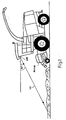
- a forage harvester with pickup is shown as an attachment for receiving swathed crop, to which the Laserentfernungsmeß device (LM) at the height of the cab (about 3.80 m) is mounted inclined at an angle of about 65 ° to the ground (shown schematically). This results in a scanning distance of about 8.15 m in front of the laser distance measuring device.
- the mounting location on the agricultural machine is determined in each case depending on the structural characteristics of the agricultural machine and the specific purposes and should be selected as high as possible for optimal contour recognition.
- the Laserentfernungsmeß device (LM) is preferably mounted height and tilt adjustable on the agricultural machine.
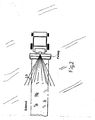
- Fig. 2 a top view of the forage harvester with pickup shown in front of the male swath.
- the Laserentfernungsmeß device (LM) is based on the extension of the forage harvester transverse to the direction of travel in the center of the machine and scans the Schwadkontur on both sides of the agricultural machine longitudinal direction symmetrically.
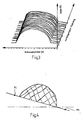
- Fig. 3 schematically shows a three-dimensional representation of the Schwadkontur scanned with the Laserentfernungsmeß device (LM) along the traveled track.
- the distances of the contour lines in the direction of travel result from the sampling frequency (pivoting time for the laser scanning beam) and the driving speed.
- Fig. 4 shows a sampled swath contour over a sloped baseline (P1-P2). Taking into account the true, inclined course of the ground baseline, which results from an interpolation of the ground contours left and right next to the swath, a more accurate calculation of the swath cross-section can be carried out with respect to the horizontal.
- Fig. 5 shows a plan view of a forage harvester when receiving different sized, adjacent Erntegutschwaden.
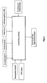
- Fig. 6 shows a block diagram of the evaluation device for calculating the sampled contour coordinates.
- the evaluation device receives the measured distance (S) to the respectively sampled contour point, the swivel angle ( ⁇ ) under which this contour point was scanned, and the inclination ( ⁇ ) and the mounting height (AH) of the laser distance measuring device (LM).
- the evaluation device then calculates the contour coordinates from these data.
- the evaluation device receives further input signals such as the driving speed, GPS data or information about the imbalance of the agricultural machine.
- the evaluation device can be integrated into the laser distance measuring device (LM) or can be embodied as one or more separate components.
- the evaluation device is connected to the central control or vehicle bus system of the agricultural machine.
- Fig. 8 shows a plan view of a contour (E). There are no contour changes in this process.
- the distance (S) here describes the distance of the Laserentfernungsmeß device (LM), in the direction of travel in even terrain, to the ground.
- LM Laserentfernungsmeß device
- Fig. 9 represents a diagram in which distance values as the FIG. 8 have been corrected.
- the scanning beam (LS) used here has a range of approx. 50m. At points (1) and (2) the maximum scanning distance is exceeded and the beam is no longer reflected. Measured values outside this swivel range are therefore invalid. The calculation then results in a cosine progression outside the valid range up to the Abtastendanschlag.
- Fig. 10 is a longitudinal section through a windrow section shown. Three consecutive measuring points are shown. In this case, the associated swivel angle ⁇ is not taken into account. Due to differences in height in the swath, shading of the laser scanning beam (LS) results. With the following context, the maximum still palpable change in the contour height ( ⁇ h) at a certain distance ( ⁇ X) of the sampled contour points in the direction of travel is described.
Description
Die Erfindung bezieht sich auf eine Vorrichtung an Landmaschinen zur berührungslosen Abtastung von sich über dem Boden erstreckenden Konturen.The invention relates to a device on agricultural machines for the contactless scanning of over the ground extending contours.
Eine derartige Vorrichtung ist aus dem Aufsatz "
Die bekannte Abtastvorrichtung ist relativ teuer, da für die Abtastung mehrere Ultraschallsensoren notwendig sind.The known scanning device is relatively expensive because multiple ultrasound sensors are necessary for scanning.
Darüber hinaus besteht ein wesentlicher Nachteil darin, daß der Abstand der Ultraschallsensoren zueinander auf der Befestigungsleiste einen Mindestabstand nicht unterschreiten darf, da es ansonsten zu einer störenden, gegenseitigen Beeinflussung der Ultraschallsensoren aufgrund der unzureichenden Fokussierung der Schallkeulen kommt. Dies beschränkt jedoch die horizontale Auflösung (Dichte der Meßpunkte) der Konturabtastung. Darüber hinaus darf auch der Abstand der Ultraschallsensoren über dem Boden bzw. über der abzutastenden Kontur nicht zu groß werden (nicht größer als ca. 1,2 m), da es wegen der relativ großen Divergenz der Schallkeulen ebenfalls zu einer störenden, gegenseitigen Beeinflussung der Ultraschallsensoren kommt.In addition, a significant disadvantage is that the distance between the ultrasonic sensors to each other on the mounting bar must not fall below a minimum distance, otherwise there is a disturbing, mutual influence of the ultrasonic sensors due to the insufficient focus of the sound lobes. However, this limits the horizontal resolution (density of measurement points) of the contour scan. In addition, the distance of the ultrasonic sensors above the ground or over the contour to be scanned must not be too large (not greater than about 1.2 m), since it also due to the relatively large divergence of the sound lobes to a disturbing, mutual influence of Ultrasonic sensors come.
Eine derart niedrige Anbringungshöhe an der Landmaschine ist oftmals schon aus konstruktiven Gründen nur schwierig zu realisieren. Außerdem wird eine derart sperrige und in niedriger Höhe angebrachte Befestigungsleiste mit mehreren Ultraschallsensoren im Feldeinsatz sehr leicht beschädigt. Die Anbringungshöhe der Befestigungsleiste zu vergrößern ist jedoch nur möglich, wenn der Abstand der Ultraschallsensoren zueinander auf der Befestigungsleiste ebenfalls vergrößert wird, was wiederum eine geringere horizontale Auflösung (Quer zur Fahrtrichtung) der Schwad-Konturabtastung bedeutet.Such a low mounting height on the agricultural machine is often difficult to realize for structural reasons. In addition, such a bulky and low-mounted mounting bar with several ultrasonic sensors in the field use very easily damaged. However, to increase the mounting height of the mounting bar is only possible if the distance between the ultrasonic sensors to each other on the mounting bar is also increased, which in turn means a lower horizontal resolution (transverse to the direction of travel) of the swath contour scan.
Der Versuch den Mindestabstand der Ultraschallsensoren zueinander dadurch zu verringern, daß diese nicht gleichzeitig arbeiten, sondern benachbarte Sensoren abwechselnd messen, erfordert eine aufwendige Ansteuerschaltung für die einzelnen Ultraschallsensoren.The attempt to reduce the minimum distance of the ultrasonic sensors to each other in that they do not work simultaneously, but alternately measure adjacent sensors, requires a complex drive circuit for the individual ultrasonic sensors.
Für eine vorausschauende Konturabtastung wie sie beispielsweise für eine automatische Lenkung entlang der abgetasteten Schwadkontur notwendig wäre, müßte die Befestigungsleiste mit den Ultraschallsensoren in aufwendiger und umständlicher Weise an ein frontseitig an der Landmaschine angeordnetes und nach vorn verlängertes zusätzliches Haltegestänge montiert werden.For a predictive Konturabtastung as would be necessary, for example, for automatic steering along the scanned Schwadkontur, the mounting bar would have to be mounted with the ultrasonic sensors in a complicated and cumbersome manner to a front of the agricultural machine arranged and forward extended additional support rod.
Ein weiterer Nachteil der bekannten Abtastvorrichtung besteht darin, daß die Genauigkeit und Zuverlässigkeit der Erntegut-Abtastung mittels Ultraschall stark von der Art und Beschaffenheit des Erntegutes und von Witterungsbedingungen abhängt.Another disadvantage of the known scanning device is that the accuracy and reliability of the crop sampling by means of ultrasound depends strongly on the type and nature of the crop and on weather conditions.
Aufgabe der Erfindung ist es eine Vorrichtung an Landmaschinen zur berührungslosen Abtastung von sich über dem Boden erstreckenden Konturen zu schaffen, die die Nachteile der vorstehend beschriebenen Vorrichtung beseitigt.The object of the invention is to provide a device on agricultural machines for non-contact scanning of extending over the ground contours, which eliminates the disadvantages of the device described above.
Diese Aufgabe wird erfindungsgemäß durch die Merkmale des Patentanspruches 1 gelöst.This object is achieved by the features of
Erfindungsgemäß wird zur berührungslosen Abtastung von sich über dem Boden erstreckenden Konturen eine an sich bekannte Laser-Entfernungsmessvorichtung bestehend aus einer Laserstrahlsende/-empfangseinrichtung verwendet, die aus der Laufzeitmessung eines ausgesandten und an einem Konturpunkt reflektierten Laser-Abtaststrahles die Entfernung zu diesem bestimmt. Die Laser-Abtaststrahlen sind nun in einem bestimmten Winkelbereich schrittweise oder stufenlos in einer Abtaststrahlen-Ebene verschwenkbar. Dabei ist die Laser-Entfernungsmessvorichtung so an der Landmaschine ausgerichtet angebracht ist, daß die Abtaststrahlen-Ebene in einem spitzen Winkel in Fahrtrichtung nach vorn zum Boden geneigt ist. Anhand einer Auswerteeinrichtung wird zu jedem Schwenkwinkel aus der gemessenen Entfernung, der Anordnung und Ausrichtung der Laser-Entfernungsmessvorichtung an der Landmaschine die zu dem Schwenkwinkel korrespondierende Lage des Konturpunktes ermittelt und wobei die Auswerteeinrichtung der Laser-Abtastvorrichtung ein Signal von einem an der Landmaschine angebrachten Neigungssensor zur Bestimmung der Schieflagen der Landmaschine empfängt und die jeweilige Schieflage bei der Konturbestimmung berücksichtigt.According to the invention for non-contact scanning of extending over the ground contours a known Laser-Entfernungsmessvorichtung consisting of a laser beam transmitting / receiving device is used, which determines the distance to this from the transit time measurement of an emitted and reflected at a contour point laser scanning beam. The laser scanning beams are now in a certain angular range gradually or continuously pivotable in a scanning beam plane. In this case, the laser rangefinder device is mounted aligned with the agricultural machine, that the scanning beam plane is inclined at an acute angle in the direction of travel forward to the ground. On the basis of an evaluation is at each swivel angle from the measured distance, the arrangement and orientation of the laser rangefinder at the Agricultural machine determines the corresponding to the pivot angle position of the contour point and wherein the evaluation of the laser scanning device receives a signal from an attached to the agricultural machine inclination sensor for determining the imbalances of the agricultural machine and takes into account the respective skew in the contour determination.
Die erfindungsgemäße Verwendung und Anordnung einer derartigen Laserentfernungsmeß-Vorrichtung hat gegenüber der aus dem Stand der Technik bekannten Abtastvorrichtung mittels Ultraschallsensoren erhebliche Vorteile.The inventive use and arrangement of such a Laserentfernungsmeß device has significant advantages over the known from the prior art scanning device by means of ultrasonic sensors.
Für die erfindungsgemäße Abtastvorrichtung ist nur eine Laserstrahlsende/-empfangseinrichtung notwendig, dadurch ist diese Abtastvorrichtung an Landmaschinen im Vergleich zur bekannten Ultraschall-Abtastvorrichtung mit mehreren Ultraschallsensoren wesentlich kostengünstiger. Bei der erfindungsgemäßen Vorrichtung erfolgt die Abtastung einer Kontur vor der Landmaschine an verschiedenen Punkten quer zur Fahrrichtung durch das Verschwenken des Laser-Abtaststrahles. Die Zahl der Abtastpunkte auf einer Abtastlinie ist dabei wesentlich größer als bei der vorbekannten Ultraschall-Abtastvorrichtung. So ergibt sich beispielsweise bei einem Schwenkwinkelbereich von ± 45° und einer Verschwenkung des Laser-Abtaststrahl in 0,5° Schritten eine Zahl von 180 Abtastpunkten. Aufgrund der geringen Divergenz des Laser-Abtaststrahles ist eine relativ hohe Auflösung (Dichte der Abtastpunkte) zu erzielen, da die Zentren benachbarter Abtastpunkte dicht beieinander liegen können, ohne daß die Abtastflecken auf der abzutastenden Kontur überlappen und eine eindeutige Zuordnung des Reflektionsortes nicht mehr möglich wäre.For the scanning device according to the invention, only one laser beam transmitting / receiving device is necessary, thus this scanning device on agricultural machines compared to the known ultrasonic scanning device with multiple ultrasonic sensors is much cheaper. In the apparatus according to the invention, the scanning of a contour in front of the agricultural machine takes place at different points transversely to the direction of travel by the pivoting of the laser scanning beam. The number of sampling points on a scan line is substantially greater than in the previously known ultrasonic scanning device. Thus, for example, with a swivel angle range of ± 45 ° and a pivoting of the laser scanning beam in 0.5 ° steps, a number of 180 scanning points. Due to the low divergence of the laser scanning a relatively high resolution (density of sampling points) is achieved because the centers of adjacent sampling points can be close to each other, without the scanning overlap on the scanned contour and a clear assignment of the reflection location would no longer be possible ,
Eine gegenseitige Beeinflussung benachbarter Sensoren wie bei der vorbekannten Abtastvorrichtung entfällt, da die Entfernungen zu den Konturpunkten nacheinander ermittelt werden.A mutual influence of adjacent sensors as in the previously known scanning omitted because the distances to the contour points are determined sequentially.
Eine weit vorausschauende Abtastung, wie sie zum Beispiel für eine automatische Lenkung entlang einer abgetasteten Kontur notwendig ist, ist mit der erfindungsgemäßen Vorrichtung in einfacher Weise zu realisieren. So ist beispielsweise bei einer Anbringungshöhe über dem Boden von 380 cm an der Landmaschine und einem Neigungswinkel (ϕ) zum Boden von 65° ein Abtastabstand vor der Landmaschine von ca. 8,15m zu erzielen. Aufgrund der geringen Divergenz des Laser-Abtaststrahles kommt es bei diesem relativ großen Abtastabstand nicht zu einer nicht akzeptierbaren Vergrößerung des Abtastfleckes wie im Fall der Ultraschallsensoren. Eine derart weit vorausschauende Konturabtastung ist mit der vorbekannten Ultraschall-Abtastvorrichtung nicht zu realisieren. Dies würde ein entsprechend langes Haltegestänge vor der Landmaschine zur Aufnahme der Befestigungsleiste für die Ultraschallsensoren erfordern, wodurch das ganze System vollkommen unpraktikabel würde.A far-ahead scanning, as is necessary, for example, for an automatic steering along a scanned contour, can be implemented in a simple manner with the device according to the invention. For example, with a mounting height above the ground of 380 cm on the agricultural machine and an inclination angle (φ) to the ground of 65 °, a scanning distance in front of the agricultural machine of approximately 8.15 m can be achieved. Due to the low divergence of the laser scanning beam, there is no unacceptable enlargement of the scanning spot at this relatively large scanning distance as in the case of the ultrasonic sensors. Such a far-reaching contour scanning can not be realized with the previously known ultrasonic scanning device. This would be a correspondingly long holding rods in front of the agricultural machine for receiving the fixing strip for Ultrasonic sensors require, making the whole system completely impractical.
Die Reflexion des Laser-Abtaststrahles ist im Unterschied zu Ultraschall relativ unabhängig von der witterungsbedingten Beschaffenheit des abzutastenden Erntegutes, wodurch die Einsatzmöglichkeiten der Laser-Abtastvorrichtung erhöht werden.The reflection of the laser scanning beam is, in contrast to ultrasound, relatively independent of the weather-related nature of the crop to be scanned, whereby the possible applications of the laser scanning device can be increased.
In einer Ausführungsform ist es vorgesehen, die Laserentfernungsmeß-Vorrichtung (LM) innerhalb der Fahrerkabine, hinter der Frontscheibe anzubringen. Staub auf der Scheibe kann aus den Signalen herausgefiltert werden und beeinträchtigt somit die Zuverlässigkeit der Abtastung nicht, die Scheibe selbst beeinträchtigt ebenfalls die Funktionstüchtigkeit nicht.In one embodiment, provision is made for the laser range finding device (LM) to be mounted inside the driver's cab, behind the windshield. Dust on the disk can be filtered out of the signals and thus does not affect the reliability of the scan, the disk itself also does not affect the functionality.
Die erfindungsgemäße Abtastvorrichtung ist aufgrund der hohen Genauigkeit, Zuverlässigkeit und aufgrund der einfachen Bauweise und Handhabung für die verschiedensten Anwendungen einsetzbar. Auf die verschieden Anwendungsverfahren der erfindungsgemäßen Vorrichtung beziehen sich die Verfahrensansprüche.The scanning device according to the invention is due to the high accuracy, reliability and due to the simple design and handling for a variety of applications used. On the different application methods of the device according to the invention, the method claims relate.
So ist es zum einen vorgesehen, während der Fahrt der Landmaschine fortlaufend entlang des zurückgelegten Weges, die Kontur über die Abtastbreite zu ermitteln und abzuspeichern. Hiermit kann die Kontur, von durch die Landmaschine aufzunehmenden Erntegutschwaden, sehr genau abgetastet und aufgezeichnet werden. An Hand der abgetasteten Kontur wird dann in einer Auswerteeinrichtung jeweils der Querschnitt des abgetasteten Erntegutschwades über der Bodengrundline ermittelt. Dabei kann der so bestimmte Schwadquerschnitt zur Einstellung der Fahrgeschwindigkeit der Landmaschine verwendet werden, wobei die Regelung beispielsweise auf konstante oder maximale Erntegutaufnahme eingestellt sein kann. Bei einem sich verkleinernden Schwadquerschnitt wird die Fahrgeschwindigkeit erhöht, so daß das pro Zeiteinheit aufgenommene Erntegut konstant ist. Wenn erntegutspezifische Dichteangaben vorliegen, so lassen sich diese ebenfalls mit dem ermittelten Schwadquerschnitt verknüpfen und in Verbindung mit einer ermittelten, überfahrenen Schwadstrecke, neben einer Volumenberechnung auch eine Gewichtsangabe, des während der Fahrt (online) aufgenommen Ernteguts, ermitteln. Darüber hinaus werden die so bestimmte schwadspezifischen Größen jeweils auch zur Einstellung von optimalen Arbeitsparametern der Erntemaschine verwendet.Thus, it is provided on the one hand, while driving the agricultural machine continuously along the path traveled, to determine the contour over the scan width and store. This allows the contour to be very accurately scanned and recorded by crop swaths to be picked up by the agricultural machine. On the basis of the scanned contour, the cross section of the scanned crop swath above the groundline is then determined in an evaluation device. In this case, the swath cross section determined in this way can be used to set the driving speed of the agricultural machine, wherein the control can be set, for example, to constant or maximum crop intake. In a shrinking Schwadquerschnitt the driving speed is increased, so that the recorded per unit time crop is constant. If crop-specific density information is available, then these can also be linked to the determined swath cross-section and, in conjunction with a determined, run-over windrow section, in addition to a volume calculation and a weight specification of harvested during travel (online) crop. In addition, the swath-specific variables determined in this way are also used in each case for setting optimum working parameters of the harvesting machine.
In einer vorteilhaften Ausgestaltung der Erfindung, kann die innerhalb der Verschwenkzeit des Abtaststrahls ermittelte Vorfahrtstrecke der Landmaschine, mit in die Entfernungsmessung einbezogen werden.In an advantageous embodiment of the invention, the determined during the pivoting time of the scanning beam Vorfahrtstrecke the agricultural machine, can be included in the distance measurement.
In besonders vorteilhafter Weise wird zur Entlastung des Landmaschinenführers die abgetastete Schwadkontur, vorzugsweise die Schwadmitte, über bekannte Mittel während der Schwadaufnahme zur automatischen Lenkung der Landmaschine eingesetzt.In a particularly advantageous manner, the sampled Schwadkontur, preferably the Schwadmitte, used by known means during swathing for automatic steering of the agricultural machine to relieve the agricultural machine operator.
In Verbindung mit einem an der Landmaschine angeordneten Echtzeitortungssystem ist es möglich, über die gesamte Einsatzfläche und/oder über Teilflächenbereiche hinweg die abgetasteten Konturen jeweils terrestrischen Koordinaten (geographische Länge und Breite, ggf. Höhe über NN - bzw. kartesische Koordinaten (x,y) bezogen auf einen Punkt des Feldes) zuzuordnen. Dabei werden neben den schwadspezifischen Größen auch die Abstände zwischen benachbarten Schwaden ermittelt und aus diesen Flächendaten und/oder Ertragsdaten generiert. Diese werden dann zur weiteren Verwendung gespeichert.In conjunction with a real-time locating system arranged on the agricultural machine, it is possible, over the entire operating area and / or over sub-area areas, to scan the scanned contours in each case for terrestrial coordinates (geographical length and latitude, if necessary height above NN or Cartesian coordinates (x, y)). related to a point of the field). In addition to the swath-specific variables, the distances between adjacent swaths are determined and generated from these surface data and / or yield data. These are then saved for further use.
Unter Verwendung eines Sensors an der Landmaschine, der die Schieflagen der Landmaschine beispielsweise beim Einsatz am Hang, beim Fahren in Senken oder über Bodenwellen ermittelt, kann, in Verbindung mit einem an der Landmaschine angeordnetem GPS-Ortungssystem, durch die Abtastung der Bodenkontur, unter Berücksichtigung der Landmaschinen-Schieflagen und -Position, ein hochgenaues, dreidimensionales Geländemodell der landwirtschaftlichen Nutzfläche erstellt werden. Die Schieflagen der Erntemaschine können auch für eine einfache Korrektur der Abtastentfernung benutzt werden.Using a sensor on the agricultural machine, which detects the imbalances of the agricultural machine, for example, when used on a slope, when driving in sinks or over bumps, in conjunction with an arranged on the agricultural machine GPS positioning system, by scanning the bottom contour, taking into account the agricultural machinery imbalances and position, a highly accurate, three-dimensional terrain model of agricultural land can be created. The harvests of the harvester can also be used for easy correction of the scanning distance.
Eine weitere Einsatzmöglichkeit der Laser-Abtastvorrichtung ist die Ermittlung des Abstandes einer Getreideährenoberfläche zur Erntemaschine. Dieses Signal wird zur Regelung der Schneidwerks-/ bzw. Haspelhöhe verwendet, wodurch eine erhebliche Entlastung des Fahrers erreicht wird. In diesem Einsatzfall können die ermittelten Abtastentfernungen weiter für die Ermittlung der tatsächlichen Schneidwerksauslastung herangezogen werden. Dafür werden die Schneidwerksgrenzen jeweils einem Schwenkwinkel der Laser-Abtastvorrichtung zugeordnet. Findet in diesem Schwenkbereich ein Kontursprung statt, so liegt an dieser Stelle eine Gutkante vor. Zwischen dieser ermittelten Gutkante und der von diesem am weitesten wegliegenden Schneidwerksgrenze läßt sich dann die Auslastung ermitteln.
Sollten durch Lagerstellen im Bestand mehrere Gutkantensprünge vorliegen, werden die jeweils äußeren Gutkantensprünge oder ein äußerer Gutkantensprung und eine der definierten Schneidwerksgrenze zur Schneidwerksauslastungsermittlung herangezogen. Dieser Auslastungswert kann dann über bekannte Mittel aufgezeichnet und/oder zur genaueren Flächenberechnung verwendet werden.Another possible use of the laser scanning device is the determination of the distance of a grain ear surface to the harvester. This signal is used to control the header / reel height, which provides significant relief for the driver. In this case, the determined scanning distances can continue to be used for the determination of the actual cutting machine utilization. For this purpose, the cutting unit boundaries are each assigned to a swivel angle of the laser scanning device. If a contour jump takes place in this swivel range, then there is a good edge at this point. The utilization can then be determined between this determined good edge and the edge of the cutting deck furthest away from it.
If multiple Gutkantensprünge exist through storage locations in the stock, the respective outer Gutkantensprünge or an outer Gutkantensprung and one of the defined cutting edge limit are used for calculating the utilization of the worksite. This utilization value can then be recorded by known means and / or used for more accurate area calculation.
Eine weitere Einsatzmöglichkeit besteht in dem Abtasten von Fahrgassen, die durch vorhergehende Arbeitseinsätze (z.B. Saat und Ausbringen von Pflanzenschutzmitteln) in einem Erntegutbestand vorhanden sind, wobei anhand dieser abgetasteten Fahrgassen über bekannte Mittel eine automatische Lenkung der Erntemaschine durchgeführt wird.A further possibility of use is the scanning of driving lanes provided by preceding operations (e.g., sowing and spreading pesticides) in a crop stock, with automatic tracking of the harvester being performed by means of these sampled lanes via known means.
Eine weitere vorteilhafte Verwendung der Laser-Abtastvorrichtung ist das Abtasten von Bearbeitungsspuren. Damit kann bei der Bearbeitung eine Zugmaschine über bekannte Mittel automatisch, entlang einer abgetasteten Spur gelenkt werden. Besonders geeignet ist diese Vorrichtung zum Abtasten von Spuren/ bzw. Furchen, wie sie beim Flügen entstehen. Vorteilhaft erweist sich dabei insbesondere der weite Erfassungsbereich der Vorrichtung. Bei einer Bearbeitungsrichtungsumkehr muß die Laser-Abtastvorrichtung nicht mechanisch verschwenkt, sondern lediglich das Regelsignal mit einem veränderten Offset versehen der automatischen Lenkeinrichtung zugeführt werden. Hierzu können beispielsweise an einem Pflug vorhandene Sensoren die Stellung des Pflugrahmens ermitteln und der Auswerte-/ bzw. Lenkreglereinrichtung mitteilen. Der Offset kann weiter per Hand und/oder durch eine Schieflagenermittlung der Landmaschine beeinflußbar sein.Another advantageous use of the laser scanning device is the scanning of machining tracks. Thus, during machining, a tractor can be steered automatically by known means along a scanned track. This device is particularly suitable for scanning tracks or furrows, as they arise during flights. In particular, the wide detection range of the device proves to be advantageous. In a machining direction reversal, the laser scanning device does not have to be mechanically pivoted, but only the control signal provided with a modified offset of the automatic steering device to be supplied. For this purpose, for example, existing sensors on a plow determine the position of the plow frame and tell the evaluation / or steering controller. The offset can be further influenced by hand and / or by an imbalance determination of the agricultural machine.
In einer weiteren Ausgestaltung kann die Laser-Abtastvorrichtung bei Landmaschinen, die eine sich anschließende Bearbeitungsspur nur in der zuvor gewählten, gleichen Bearbeitungsrichtung zulassen (z.B.: Beetflug, Mähwerke), die Laser-Abtastvorrichtung direkt über der Fahrspur bzw. Bearbeitungskante an dem Bearbeitungsgerät oder dem Zugfahrzeug bzw. der Erntemaschine angebracht werden. Eine Umrechnung der ermittelten Spurposition oder ein Aufschalten eines Offsets kann dann entfallen.In a further embodiment, the laser scanning device in agricultural machinery, which allow a subsequent processing track only in the previously selected, same processing direction (eg: bed flight, mowers), the laser scanning device directly above the lane or processing edge on the processing unit or the Towing vehicle or the harvester to be attached. A conversion of the determined track position or an activation of an offset can then be omitted.
Anhand der beigefügten Zeichnungen soll die Erfindung näher veranschaulicht werden. Es zeigt:
- Fig. 1
- die Seitenansicht eines Feldhäckslers mit Laser-Abtastvorrichtung,
- Fig. 2
- die Draufsicht auf einen Feldhäcksler mit Laser-Abtastvorrichtung zur Schwadabtastung,
- Fig. 3
- die dreidimensionale Darstellung einer mit der erfindungsgemäßen Vorrichtung abgetasteten Schwadkontur entlang der Fahrstrecke,
- Fig.4
- den Querschnitt eines abgetasteten Schwadquerschnittes über einem geneigten Boden,
- Fig. 5
- die Draufsicht auf verschiedene Schwade auf einer Wiese,
- Fig. 6
- ein Blockschaltbild der Auswerteeinrichtung mit ihren Eingangssignalen,
- Fig. 7 bis Fig. 10
- die geometrischen Verhältnisse der Laserstrahl- Abtastung.
- Fig. 1
- the side view of a forage harvester with laser scanning device,
- Fig. 2
- the top view of a forage harvester with laser scanning device for swath scanning,
- Fig. 3
- the three-dimensional representation of a scanned with the device according to the invention swath contour along the route,
- Figure 4
- the cross-section of a scanned swath cross-section over a sloping floor,
- Fig. 5
- the top view of different swathes in a meadow,
- Fig. 6
- a block diagram of the evaluation device with their input signals,
- FIGS. 7 to 10
- the geometric relationships of the laser beam scanning.
In
Zum besseren Verständnis ist in
Zum besseren Verständnis zeigen die
Dabei bedeutet:
- AH:
- die Anbringungshöhe der Laserentfernungsmeß-Vorrichtung an der Landmaschine über dem Boden,
- ϕ:
- den Neigungswinkel der Abtaststrahlen-Ebene zur Vertikalen,
- h:
- die Höhe des abgetasteten Konturpunktes über dem Boden,
- PE:
- die projizierte Entfernung zwischen der Laserentfernungsmeß-Vorrichtung und dem abgetasteten Konturpunkt,
- S:
- die gemessene Entfernung zwischen der Laserentfernungsmeß-Vorrichtung und einem abgetasteten Knotenpunkt,
- αi :
- der i-te Schwenkwinkel des Laser-Abtaststrahles in der Abtaststrahlen-Ebene,
- S0:
- die gemessene Entfernung für den Mittelpunktstrahl,
- Si:
- die gemessene Entfernung für den um αi verschwenkten Laser-Abtaststrahl,
- AH:
- the mounting height of the laser distance measuring device on the agricultural machine above the ground,
- φ:
- the angle of inclination of the scanning beam plane to the vertical,
- H:
- the height of the sampled contour point above the ground,
- PE:
- the projected distance between the laser distance measuring device and the scanned contour point,
- S:
- the measured distance between the laser distance measuring device and a scanned node,
- α i :
- the i-th tilt angle of the laser scanning beam in the scanning beam plane,
- S 0 :
- the measured distance for the center beam,
- S i :
- the measured distance for the laser scanning beam pivoted by α i ,
In ![]()
![]()
Um Meßwerte für eine orthogonal zur Fahrtrichtung liegende Kontur (E) im Abstand (S0), bei welcher der Mittelpunktsstrahl direkt zum Boden gemessen wird, zu erhalten, müssen die aus der Mittellage verschwenkten Abstandsmeßwerte LS(α≠0) umgerechnet werden. Die Umrechnungsformel lautet dafür: ![]()
![]()
![]()
In order to obtain measured values for a contour (E) orthogonal to the direction of travel at a distance (S 0 ) at which the midpoint beam is measured directly to the ground, the distance measured values LS (α ≠ 0) pivoted from the central position must be converted. The conversion formula is: ![]()
An den Stellen (3) und (4) wurden jeweils eine kürzere Abtastweite des Abtaststrahls ermittelt. An diese Stellen liegen Erhöhungen in der Kontur vor. Sie zeigen jeweils die Lage und den Querschnitt eines Schwades an. Der Schwad an der Stelle (3) liegt etwas seitlich von der Mitte der Erntemaschinenfahrtrichtung. Die Schwadmitte kann ermittelt und bezogen auf den Mittelpunktstrahl zur automatischen Lenkung einer Landmaschine verwendet werden.
An der Stelle (4) wird ein weiterer Schwad dargestellt. Über die jeweils ermittelten Winkellagen der beiden Schwadmittelpunkte, kann der Abstand der Schwaden ermittelt und in Verbindung mit den schwadspezifischen Größen (Länge, Querschnittsfläche, Dicht) einer Ernteflächenermittlung bzw. einer Ertragskartierung zugeführt werden.At points (3) and (4), a shorter scan width of the scanning beam was determined in each case. There are elevations in the contour at these points. They each indicate the position and the cross section of a swath. The swath at location (3) is slightly laterally from the center of the harvester travel direction. The Schwadmitte can be determined and used based on the center beam for automatic steering of an agricultural machine.
At point (4) another swath is shown. About the respectively determined angular positions of the two Schwadmittelpunkte, the distance of the windrows can be determined and fed in conjunction with the Schwadspezifischen variables (length, cross-sectional area, density) of a harvesting area determination or yield mapping.
In ![]()
Ist beispielsweise durch eine Fahrgeschwindigkeit von v= 10km/h und einer Schwenkwinkelfrequenz 25Hz (Abtastfrequenz) ein Abtastabstand von ΔX=11,1 cm vorgegeben, so ergibt sich bei einem Neigungswinkel von ϕ=65° ein maximaler, abtastbarer Höhenunterschied von Δh=5,2cm. Ein derartiger Wert ist für die verfahrensgemäßen Anwendungen voll ausreichend.In ![]()
If, for example, a scanning distance of ΔX = 11.1 cm is specified by a travel speed of v = 10 km / h and a swivel angle frequency 25 Hz (scanning frequency), a maximum, scannable height difference of Δh = 5 results for an inclination angle of φ = 65 °. 2cm. Such a value is fully sufficient for the method according to the application.
Claims (10)
- Apparatus on agricultural machines for contactlessly scanning contours extending over the ground,
characterised by
a laser distance measuring device (LM) comprising a laser beam emitting/receiving device which determines the distance in relation to a contour point from the transit time measurement of the laser scanning beam (LS) which is emitted and reflected at the contour point, wherein
the laser scanning beam (LS) is pivotable stepwise or steplessly in a scanning beam plane in a given angular circle,
the laser distance measuring device (LM) is mounted in oriented relationship to the agricultural machine in such a way that the scanning beam plane is inclined forwardly in the direction of travel relative to the ground at an acute angle (ϕ), and
there is provided an evaluation device which at each pivotal angle (α) ascertains from the measured distance (S), the arrangement and orientation of the laser distance measuring device (LM) on the agricultural machine the position of the contour point corresponding to the pivotal angle and wherein the evaluation device of the laser scanning device receives a signal from an inclination sensor mounted to the agricultural machine for determining the sloping positions of the agricultural machine and takes account of the respective sloping position in determining the contour. - Apparatus according to claim 1 characterised in that the laser distance measuring device (LM) is fixed adjustably in inclination to the agricultural machine so that different inclinations of the laser scanning beam (LS) can be set relative to the ground.
- A method of contour scanning with an apparatus according to claims 1 and 2 characterised in that during the travel of the agricultural machine the contour is continuously ascertained from the ascertained distance values over the scanning width and stored.
- A method according to claim 3 characterised in that a track to be followed by the agricultural machine is ascertained from the contour and/or from the sums of consecutive contours.
- A method according to claims 3 and 4 characterised in that the ascertained track serves by way of means for automatically steering an agricultural machine along said track.
- A method according to claims 3 to 5 characterised in that the signal generated for automatic steering can be so adapted by an offset which can be influenced by hand and/or by the sloping positions of the agricultural machine and/or by a working direction recognition step that parallel displacement is possible between the ascertained track and the centre point beam.
- A method according to claims 3 to 6 characterised in that the configuration of the ground base line under a scanned crop material swathe is ascertained by scanning the ground base line which is not covered with swathe at both sides of the crop material swathe and is used for more accurately determining the swathe cross-section.
- A method of contour scanning with an apparatus according to claim 1 characterised in that the ground contour of an agricultural usable surface is scanned for producing a highly accurate three-dimensional terrain model, wherein the respectively scanned contour points of the ground is associated with terrestrial co-ordinates by way of a real-time locating system arranged on the agricultural machine having regard to at least one agricultural machine sloping position.
- A method of contour scanning with an apparatus according to claim 1 characterised in that the ear surface of a cornfield and the ascertained contour serves for regulation of the cutting mechanism height and/or the drum height and/or for ascertaining the cutting mechanism loading.
- A method of contour scanning with an apparatus according to claim 1 characterised in that the distance ascertained during the pivotal time of the scanning beam is respectively corrected by the path distance travelled.
Applications Claiming Priority (2)
| Application Number | Priority Date | Filing Date | Title |
|---|---|---|---|
| DE19726917A DE19726917A1 (en) | 1997-06-25 | 1997-06-25 | Device on agricultural machinery for contactless scanning of contours extending over the ground |
| EP98105831A EP0887660B1 (en) | 1997-06-25 | 1998-03-31 | Device mounted on agricultural machines for contactless mapping of ground surface contours and accompanying method |
Related Parent Applications (2)
| Application Number | Title | Priority Date | Filing Date |
|---|---|---|---|
| EP98105831A Division EP0887660B1 (en) | 1997-06-25 | 1998-03-31 | Device mounted on agricultural machines for contactless mapping of ground surface contours and accompanying method |
| EP98105831.6 Division | 1998-03-31 |
Publications (3)
| Publication Number | Publication Date |
|---|---|
| EP1630574A2 EP1630574A2 (en) | 2006-03-01 |
| EP1630574A3 EP1630574A3 (en) | 2009-12-16 |
| EP1630574B1 true EP1630574B1 (en) | 2013-07-31 |
Family
ID=7833572
Family Applications (3)
| Application Number | Title | Priority Date | Filing Date |
|---|---|---|---|
| EP05025026A Withdrawn EP1630573A3 (en) | 1997-06-25 | 1998-03-31 | Device mounted on agricultural machines for contactless mapping of ground surface contours |
| EP05025272.5A Expired - Lifetime EP1630574B1 (en) | 1997-06-25 | 1998-03-31 | Device mounted on agricultural machines for contactless mapping of ground surface contours |
| EP98105831A Expired - Lifetime EP0887660B1 (en) | 1997-06-25 | 1998-03-31 | Device mounted on agricultural machines for contactless mapping of ground surface contours and accompanying method |
Family Applications Before (1)
| Application Number | Title | Priority Date | Filing Date |
|---|---|---|---|
| EP05025026A Withdrawn EP1630573A3 (en) | 1997-06-25 | 1998-03-31 | Device mounted on agricultural machines for contactless mapping of ground surface contours |
Family Applications After (1)
| Application Number | Title | Priority Date | Filing Date |
|---|---|---|---|
| EP98105831A Expired - Lifetime EP0887660B1 (en) | 1997-06-25 | 1998-03-31 | Device mounted on agricultural machines for contactless mapping of ground surface contours and accompanying method |
Country Status (5)
| Country | Link |
|---|---|
| US (1) | US6389785B1 (en) |
| EP (3) | EP1630573A3 (en) |
| AR (1) | AR015898A1 (en) |
| DE (3) | DE19726917A1 (en) |
| UA (1) | UA66341C2 (en) |
Cited By (2)
| Publication number | Priority date | Publication date | Assignee | Title |
|---|---|---|---|---|
| US11369052B2 (en) | 2019-08-15 | 2022-06-28 | Cnh Industrial America Llc | System and method for monitoring plugging of basket assemblies of an agricultural implement |
| EP4324315A1 (en) | 2022-08-16 | 2024-02-21 | CLAAS E-Systems GmbH | Swath acquisition device |
Families Citing this family (115)
| Publication number | Priority date | Publication date | Assignee | Title |
|---|---|---|---|---|
| DE19743884C2 (en) | 1997-10-04 | 2003-10-09 | Claas Selbstfahr Erntemasch | Device and method for the contactless detection of processing limits or corresponding guide variables |
| SE509209C2 (en) * | 1997-11-28 | 1998-12-14 | Spectra Precision Ab | Device and method for determining the position of the machining part |
| DE19845666B4 (en) | 1998-10-05 | 2005-08-25 | Claas Selbstfahrende Erntemaschinen Gmbh | Automatic steering with ultrasonic locating device |
| DE19918551B4 (en) * | 1999-04-23 | 2015-04-02 | Deere & Company | harvester |
| NL1013349C2 (en) * | 1999-10-20 | 2001-04-23 | Lely Res Holding | Device for defining an area as well as a vehicle suitable for use in the device. |
| DK173577B1 (en) * | 2000-01-12 | 2001-03-19 | Eco Dan Aps | Method for detecting a track in the form of an elongated furrow or back in a field, combination of an agricultural implement |
| DE10221948B4 (en) * | 2001-05-14 | 2004-03-11 | Kümmel, Knut, Dipl., -Ing. | Process and system for volume-specific influencing of soil and plants |
| DE10129136A1 (en) | 2001-06-16 | 2002-12-19 | Deere & Co | Device for the automatic steering of an agricultural work vehicle |
| DE10129133A1 (en) | 2001-06-16 | 2002-12-19 | Deere & Co | Device for the automatic steering of an agricultural work vehicle |
| DE10129135B4 (en) | 2001-06-16 | 2013-10-24 | Deere & Company | Device for determining the position of an agricultural work vehicle and an agricultural work vehicle with this |
| US6615570B2 (en) | 2001-06-28 | 2003-09-09 | Deere & Company | Header position control with forward contour prediction |
| DE10130665A1 (en) * | 2001-06-28 | 2003-01-23 | Deere & Co | Device for measuring the amount of plants in a field |
| US6661524B2 (en) * | 2001-07-09 | 2003-12-09 | United Defense, L.P. | Vehicle regional scanner |
| DE10135457A1 (en) * | 2001-07-20 | 2003-02-06 | Adc Automotive Dist Control | Optical sensor device for use in automobile positioned behind transparent panel with lamella elements between latter and optical transmitter-receiver |
| DE10204702A1 (en) * | 2002-02-05 | 2003-08-14 | Claas Selbstfahr Erntemasch | Location system on self-propelled agricultural machines |
| DE10227484A1 (en) * | 2002-06-19 | 2004-02-26 | Claas Selbstfahrende Erntemaschinen Gmbh | Device and method for controlling the position of a harvesting device of agricultural harvesting machines |
| US20050081498A1 (en) * | 2003-03-19 | 2005-04-21 | John Harvey | Method of harvesting sugarcane |
| US20060185340A1 (en) * | 2003-05-19 | 2006-08-24 | Eyre Robert J | Cutting and threshing header for harvesting machine |
| US7916898B2 (en) | 2003-09-15 | 2011-03-29 | Deere & Company | Method and system for identifying an edge of a crop |
| US6839127B1 (en) * | 2003-09-15 | 2005-01-04 | Deere & Company | Optical range finder having a micro-mirror array |
| DE10342922A1 (en) * | 2003-09-15 | 2005-05-19 | Claas Selbstfahrende Erntemaschinen Gmbh | Chopping and distribution device |
| DE10351861A1 (en) | 2003-11-06 | 2005-06-09 | Deere & Company, Moline | Method and steering system for automatically steering an agricultural machine |
| DE10352314A1 (en) * | 2003-11-06 | 2005-06-09 | Gebr. Pöttinger GmbH | Arrangement for adjusting amount of seed released by agricultural device to inclination of surface and for creation of driving track |
| US7412905B1 (en) | 2004-05-31 | 2008-08-19 | Richard Anthony Bishel | Paddle sensor |
| US7248968B2 (en) | 2004-10-29 | 2007-07-24 | Deere & Company | Obstacle detection using stereo vision |
| DE102005000771A1 (en) * | 2005-01-05 | 2006-08-24 | Langlott, Jürgen | Self-propelled harvester controlling method, involves allocating detected and mapped/ factored biomass stock data by software, and creating control process to control and adjust all functional units among each other, and speed of harvester |
| DE102005004508A1 (en) | 2005-01-31 | 2006-08-17 | Claas Selbstfahrende Erntemaschinen Gmbh | Device for the uniform loading of working machines |
| DE102005005556B4 (en) * | 2005-02-07 | 2016-02-11 | Alois Pöttinger Maschinenfabrik Gmbh | Device for controlling an agricultural harvester |
| US7168174B2 (en) * | 2005-03-14 | 2007-01-30 | Trimble Navigation Limited | Method and apparatus for machine element control |
| DE102005024735B4 (en) * | 2005-05-31 | 2007-06-28 | Rheinmetall Landsysteme Gmbh | Method for distance determination and display, and distance measuring system, in particular for supporting the laying of a bridge |
| US10705533B1 (en) * | 2005-05-31 | 2020-07-07 | Richard Anthony Bishel | Autonomous lawnmower |
| US8185275B2 (en) * | 2005-07-01 | 2012-05-22 | Deere & Company | System for vehicular guidance with respect to harvested crop |
| DE102005041550A1 (en) * | 2005-08-31 | 2007-03-01 | Agrocom Gmbh & Co. Agrarsysteme Kg | Steering system for e.g. tractor, has track guiding system with route detecting systems that are coupled by data processing units and controller that defines criteria for switching between detecting systems based on structure of territory |
| US7404355B2 (en) | 2006-01-31 | 2008-07-29 | Deere & Company | Tractor and baler combination with automatic baling and tractor halt control |
| DE102006011135A1 (en) * | 2006-03-10 | 2007-09-20 | Deere & Company, Moline | control device |
| EP1914564B1 (en) * | 2006-10-19 | 2010-06-23 | Sick Ag | Optical detection device |
| DE102006055858A1 (en) * | 2006-11-27 | 2008-05-29 | Carl Zeiss Ag | Method and arrangement for controlling a vehicle |
| US7865285B2 (en) * | 2006-12-27 | 2011-01-04 | Caterpillar Inc | Machine control system and method |
| US7647753B2 (en) * | 2006-12-30 | 2010-01-19 | Headsight, Inc. | Header height control system and method |
| EP2057875A1 (en) * | 2007-11-08 | 2009-05-13 | Leibniz-Institut für Agrartechnik Potsdam-Bornim e.V. (ATB) | Method and assembly for recording plant resources on agricultural machines |
| DE102008007451A1 (en) * | 2008-01-31 | 2009-08-06 | Carl Zeiss Microimaging Gmbh | Arrangement for three-dimensional mapping of scene, has receiving unit with two-dimensional detector surface for local resolution detection of light, which is reflected or controlled from objects located in different areas of scene |
| US8280621B2 (en) | 2008-04-15 | 2012-10-02 | Caterpillar Inc. | Vehicle collision avoidance system |
| US20090259399A1 (en) * | 2008-04-15 | 2009-10-15 | Caterpillar Inc. | Obstacle detection method and system |
| US8060269B2 (en) * | 2008-04-16 | 2011-11-15 | Cnh America Llc | Swath line creation including slope compensation for an automatic guidance system of a work vehicle |
| DE102008043716B4 (en) | 2008-11-13 | 2012-06-21 | Deere & Company | Device and method for recording the stock density of plants in a field |
| US7870709B2 (en) * | 2009-02-25 | 2011-01-18 | Chn America Llc | Automatic lateral tilt control of a header in stubble height mode using machine level sensor |
| EP2368419B1 (en) * | 2010-03-23 | 2016-08-10 | CLAAS E-Systems KGaA mbH & Co KG | A method of detecting a structure in a field, a method of steering an agricultural vehicle and an agricultural vehicle |
| DE102011017621A1 (en) | 2011-04-27 | 2012-10-31 | Deere & Company | Arrangement and method for detecting the amount of plants in a field |
| DE102011100054A1 (en) | 2011-04-29 | 2012-10-31 | Alois Pöttinger Maschinenfabrik Gmbh | Agricultural machine |
| GB201111691D0 (en) * | 2011-07-07 | 2011-08-24 | Lrb Global Consulting Ltd | A parking sensor |
| US11212962B2 (en) * | 2013-02-20 | 2022-01-04 | Deere & Company | Field condition determination |
| US8972119B2 (en) * | 2013-03-15 | 2015-03-03 | Novatel Inc. | System and method for heavy equipment navigation and working edge positioning |
| EP2798928B1 (en) * | 2013-04-29 | 2024-02-07 | CLAAS E-Systems GmbH | Operating system for and method of operating an automatic guidance system of an agricultural vehicle |
| GB2521343B (en) * | 2013-10-23 | 2018-05-23 | Househam Sprayers Ltd | Agricultural Sprayer |
| BE1021107B1 (en) | 2013-10-28 | 2016-01-18 | Cnh Industrial Belgium Nv | SWATH SENSOR FOR FIELD FORMER |
| US10371561B2 (en) * | 2013-11-01 | 2019-08-06 | Iowa State University Research Foundation, Inc. | Yield measurement and base cutter height control systems for a harvester |
| US20150195991A1 (en) | 2014-01-15 | 2015-07-16 | Cnh America Llc | Header height control system for an agricultural harvester |
| DE102014104619A1 (en) * | 2014-04-02 | 2015-10-08 | Claas Agrosystems Kgaa Mbh & Co. Kg | Planning system and method for planning fieldwork |
| DE102014206801A1 (en) * | 2014-04-09 | 2015-11-05 | Robert Bosch Gmbh | Assistance device for a mobile work machine, mobile work machine and combination of two mobile work machines |
| US9807933B2 (en) | 2014-10-20 | 2017-11-07 | Cnh Industrial America Llc | Sensor equipped agricultural harvester |
| DE102015102080A1 (en) * | 2015-02-13 | 2016-08-18 | Horsch Leeb Application Systems Gmbh | Device for dispensing liquids and method for controlling the movement of at least two extension arms of an agricultural field sprayer |
| US9844184B2 (en) * | 2015-03-17 | 2017-12-19 | Agco Corporation | Header position sensing system for an agricultural harvester |
| US9585309B2 (en) * | 2015-07-14 | 2017-03-07 | Cnh Industrial America Llc | Header height control system for an agricultural harvester |
| US9930834B2 (en) | 2015-10-29 | 2018-04-03 | Deere & Company | Agricultural baler control system |
| DE102015118767A1 (en) | 2015-11-03 | 2017-05-04 | Claas Selbstfahrende Erntemaschinen Gmbh | Environment detection device for agricultural machine |
| DE102016121523A1 (en) | 2015-11-17 | 2017-05-18 | Lacos Computerservice Gmbh | Method for predicatively generating data for controlling a route and an operating sequence for agricultural vehicles and machines |
| WO2018086764A1 (en) | 2016-11-10 | 2018-05-17 | Lacos Computerservice Gmbh | Method for predictively generating data for controlling a travel path and an operating sequence for agricultural vehicles and machines |
| BE1023243B1 (en) | 2015-11-24 | 2017-01-06 | Cnh Industrial Belgium Nv | CONTROL SYSTEM FOR A HARVESTER AND HARVESTER |
| JP6794115B2 (en) * | 2016-02-03 | 2020-12-02 | 小橋工業株式会社 | Work machine and work system |
| US9854725B2 (en) * | 2016-03-28 | 2018-01-02 | Cnh Industrial America Llc | Laser guidance system for agricultural operations |
| US10190288B2 (en) * | 2016-04-08 | 2019-01-29 | Ace/Avant Concrete Construction Co., Inc. | Excavation measurement with light curtain |
| DE102016118651A1 (en) | 2016-09-30 | 2018-04-05 | Claas Selbstfahrende Erntemaschinen Gmbh | Self-propelled agricultural machine |
| DE102016118667A1 (en) | 2016-09-30 | 2018-04-05 | Claas Selbstfahrende Erntemaschinen Gmbh | Self-propelled agricultural machine |
| TWI627380B (en) * | 2016-11-23 | 2018-06-21 | 綠點高新科技股份有限公司 | Method And System For Estimating Contour Of A Surface Of A 3D Object |
| HUE052985T2 (en) * | 2017-02-06 | 2021-06-28 | Bilberry Sas | Weeding systems and methods, railway weeding vehicles |
| EP3357332B1 (en) * | 2017-02-06 | 2022-04-13 | Bilberry Sas | Agricultural sprayer |
| FR3063206B1 (en) * | 2017-02-24 | 2021-08-13 | Bilberry Sas | AGRICULTURAL SPREADING CONTROL SYSTEM |
| CN110546452B (en) * | 2017-04-21 | 2022-10-18 | 发茂特有限公司 | Product and method for measuring the surface topography of crops or pastures |
| DE102017207347A1 (en) | 2017-05-02 | 2018-11-08 | Deere & Company | Method and arrangement for controlling the speed of a baling press |
| BE1024834B1 (en) * | 2017-05-09 | 2018-07-13 | Cnh Industrial Belgium Nv | AGRICULTURAL SYSTEM |
| BE1024928B1 (en) | 2017-05-09 | 2018-08-13 | Cnh Industrial Belgium Nv | IMPROVEMENTS IN OR RELATING TO TRACTOR / BALER PRESS COMBINATIONS |
| EP3409097B1 (en) * | 2017-06-02 | 2020-07-22 | CLAAS E-Systems GmbH | Agricultural working machine |
| CN107339948B (en) * | 2017-06-28 | 2023-07-07 | 沈阳工业大学 | Equipment and method for detecting distance between spray boom and crop plant |
| US10827676B2 (en) * | 2018-01-29 | 2020-11-10 | Deere & Company | Monitor and control system for a harvester |
| US11744180B2 (en) | 2018-01-29 | 2023-09-05 | Deere & Company | Harvester crop mapping |
| CN110352697B (en) * | 2018-04-09 | 2022-05-17 | 迪尔公司 | System for controlling operating parameters of a harvesting header and agricultural harvester |
| NO344567B1 (en) * | 2018-04-12 | 2020-02-03 | Geonord As | Construction machine guidance system |
| RU182585U1 (en) * | 2018-04-12 | 2018-08-23 | Федеральное государственное бюджетное научное учреждение "Агрофизический научно-исследовательский институт" (ФГБНУ АФИ) | DEVICE FOR DETERMINING THE QUALITY OF TILLING THE SOIL OF A SOIL PROCESSING MACHINE |
| WO2019234539A1 (en) | 2018-06-08 | 2019-12-12 | Agco Corporation | Auto reel height |
| CN108872998B (en) * | 2018-09-04 | 2023-08-29 | 华南农业大学 | Crop position detection equipment and detection method |
| DE102018131142A1 (en) | 2018-12-06 | 2020-06-10 | Claas Selbstfahrende Erntemaschinen Gmbh | Agricultural machine and method for operating an agricultural machine |
| US11199845B2 (en) | 2019-03-05 | 2021-12-14 | Cnh Industrial America Llc | System and method for distributing and compressing crop material for ensilage |
| US11076626B2 (en) | 2019-03-05 | 2021-08-03 | Cnh Industrial America Llc | System and method for distributing and compressing crop material for ensilage |
| US11385338B2 (en) | 2019-03-06 | 2022-07-12 | Cnh Industrial America Llc | System and method for disregarding obscured sensor data during the performance of an agricultural operation |
| DE102019204243A1 (en) * | 2019-03-27 | 2020-10-01 | Zf Friedrichshafen Ag | Method and control device for track guidance |
| DE102019204251A1 (en) * | 2019-03-27 | 2020-10-01 | Zf Friedrichshafen Ag | Method and system for line detection on an agricultural area |
| DE102019111040A1 (en) | 2019-04-29 | 2020-10-29 | Claas Selbstfahrende Erntemaschinen Gmbh | Method for operating a self-propelled agricultural work machine |
| DE102019119126A1 (en) * | 2019-07-15 | 2021-01-21 | Claas Selbstfahrende Erntemaschinen Gmbh | Agricultural harvester |
| US11905675B2 (en) * | 2019-08-05 | 2024-02-20 | Topcon Positioning Systems, Inc. | Vision-based blade positioning |
| DE102019123207A1 (en) * | 2019-08-29 | 2021-03-04 | Claas Selbstfahrende Erntemaschinen Gmbh | Method for signal evaluation of signals from a range finder |
| US11659785B2 (en) * | 2019-10-23 | 2023-05-30 | Cnh Industrial America Llc | Method and system for controlling the height of an agricultural implement relative to the ground |
| DE102019129205A1 (en) * | 2019-10-29 | 2021-04-29 | Horsch Leeb Application Systems Gmbh | Agricultural machine with a system for calculating a terrain relief and method for operating an agricultural machine |
| US11864484B2 (en) | 2019-11-06 | 2024-01-09 | Cnh Industrial Canada, Ltd. | System and method for determining soil clod size or residue coverage of a field during a non-soil-working operation |
| US20210185916A1 (en) * | 2019-12-23 | 2021-06-24 | Cnh Industrial America Llc | Sensor assembly for an agricultural header |
| JP6700500B1 (en) * | 2020-03-26 | 2020-05-27 | 株式会社レグミン | Agricultural work vehicle, control device and program |
| JP7329018B2 (en) * | 2020-04-03 | 2023-08-17 | ヤンマーパワーテクノロジー株式会社 | combine |
| US11659787B2 (en) * | 2020-04-03 | 2023-05-30 | Cnh Industrial America Llc | Harvesting head reel-crop engagement |
| AT523999A1 (en) | 2020-06-19 | 2022-01-15 | Ideas Gmbh & Co Kg | Device on agricultural machines for scanning contours and method for controlling the agricultural machine |
| RU2741746C1 (en) * | 2020-08-11 | 2021-01-28 | Федеральное государственное бюджетное образовательное учреждение высшего образования "Чувашский государственный университет имени И.Н. Ульянова" | Method of monitoring quality of tillage on agrolandscapes in field conditions |
| JP7094338B2 (en) * | 2020-10-14 | 2022-07-01 | 株式会社クボタ | Work vehicle |
| JP7268899B2 (en) * | 2020-11-11 | 2023-05-08 | 小橋工業株式会社 | Work machine and work system |
| CN114593691A (en) * | 2020-12-04 | 2022-06-07 | 长安大学 | Method and device capable of realizing single-line laser reconstruction of three-dimensional scene |
| CN113050103A (en) * | 2021-02-05 | 2021-06-29 | 上海擎朗智能科技有限公司 | Ground detection method, device, electronic equipment, system and medium |
| US11856891B2 (en) * | 2021-03-26 | 2024-01-02 | Cnh Industrial America Llc | Systems and methods for controlling an agricultural header |
| US20220400606A1 (en) * | 2021-06-18 | 2022-12-22 | Green Industry Innovators, L.L.C. | Landscaping equipment with included laser and methods of operation |
Family Cites Families (25)
| Publication number | Priority date | Publication date | Assignee | Title |
|---|---|---|---|---|
| DE2455836C3 (en) * | 1974-11-26 | 1982-01-21 | Gebr.Claas Maschinenfabrik GmbH, 4834 Harsewinkel | Device for the automatic guidance of agricultural machinery |
| US4077488A (en) * | 1976-06-15 | 1978-03-07 | Sperry Rand Corporation | Guidance assist system for agricultural machines |
| US4299483A (en) * | 1979-11-13 | 1981-11-10 | Grove Thomas C | Path alignment apparatus |
| EP0068626B1 (en) * | 1981-07-01 | 1987-08-19 | Imperial Chemical Industries Plc | Vehicle guidance system particularly for use in agriculture |
| JPS6434202A (en) * | 1987-07-30 | 1989-02-03 | Kubota Ltd | Working wagon of automatic conduct type |
| US5019983A (en) | 1989-02-21 | 1991-05-28 | Eaton Corporation | Automatic steering apparatus using reflected signals |
| US5956250A (en) * | 1990-02-05 | 1999-09-21 | Caterpillar Inc. | Apparatus and method for autonomous vehicle navigation using absolute data |
| DE4318798A1 (en) * | 1992-11-24 | 1994-06-01 | Holger Muehlberger | Automatically controlled agricultural vehicle for moving across defined area - has on board sensors that detect defined land features and move along specified paths |
| DE9312542U1 (en) * | 1992-11-24 | 1993-10-07 | Muehlberger Holger | Automatically self-propelled machine for processing defined areas |
| DE4342171C2 (en) * | 1993-07-17 | 1996-01-25 | Georg Duerrstein | Soil preparation methods, in particular for fertilizing agricultural land |
| GB2308256B (en) * | 1995-05-02 | 2000-02-09 | Tokimec Inc | An apparatus for measuring a shape of road surface |
| US5509486A (en) * | 1994-08-12 | 1996-04-23 | Loral Corporation | Method of steering an agricultural vehicle |
| DE4431824C1 (en) | 1994-09-07 | 1996-05-02 | Claas Ohg | Combine operation with operational data register |
| US5666792A (en) * | 1994-12-30 | 1997-09-16 | Mullins; Donald B. | Remotely guided brush cutting, chipping and clearing apparatus and method |
| DE19508942A1 (en) | 1995-03-13 | 1996-09-19 | Claas Ohg | Reflex locator |
| DE19508941A1 (en) | 1995-03-13 | 1996-09-19 | Claas Ohg | Locating device |
| US5612864A (en) * | 1995-06-20 | 1997-03-18 | Caterpillar Inc. | Apparatus and method for determining the position of a work implement |
| DE19544112C2 (en) | 1995-11-27 | 2001-10-18 | Claas Kgaa Mbh | Process for generating digital terrain relief models |
| US5928309A (en) | 1996-02-05 | 1999-07-27 | Korver; Kelvin | Navigation/guidance system for a land-based vehicle |
| DE69709482T2 (en) | 1996-04-19 | 2002-11-07 | Univ Pittsburgh Carnegie Mello | Crop line locator with image processing |
| US5935183A (en) | 1996-05-20 | 1999-08-10 | Caterpillar Inc. | Method and system for determining the relationship between a laser plane and an external coordinate system |
| DE19623754A1 (en) | 1996-06-14 | 1997-12-18 | Claas Ohg | Harvester with a header processing device that is height-adjustable in relation to the ground |
| DE19719939A1 (en) * | 1997-05-13 | 1998-11-19 | Claas Ohg | Automatically steerable harvesting machine |
| US5905968A (en) | 1997-09-12 | 1999-05-18 | Caterpillar Inc. | Method and apparatus for controlling an earthworking implement to preserve a crown on a road surface |
| DE19743884C2 (en) * | 1997-10-04 | 2003-10-09 | Claas Selbstfahr Erntemasch | Device and method for the contactless detection of processing limits or corresponding guide variables |
-
1997
- 1997-06-25 DE DE19726917A patent/DE19726917A1/en not_active Withdrawn
- 1997-06-25 DE DE29724569U patent/DE29724569U1/en not_active Expired - Lifetime
-
1998
- 1998-03-31 EP EP05025026A patent/EP1630573A3/en not_active Withdrawn
- 1998-03-31 DE DE59814455T patent/DE59814455D1/en not_active Expired - Lifetime
- 1998-03-31 EP EP05025272.5A patent/EP1630574B1/en not_active Expired - Lifetime
- 1998-03-31 EP EP98105831A patent/EP0887660B1/en not_active Expired - Lifetime
- 1998-06-18 AR ARP980102906A patent/AR015898A1/en unknown
- 1998-06-24 UA UA98063313A patent/UA66341C2/en unknown
-
2000
- 2000-04-05 US US09/543,323 patent/US6389785B1/en not_active Expired - Fee Related
Cited By (3)
| Publication number | Priority date | Publication date | Assignee | Title |
|---|---|---|---|---|
| US11369052B2 (en) | 2019-08-15 | 2022-06-28 | Cnh Industrial America Llc | System and method for monitoring plugging of basket assemblies of an agricultural implement |
| EP4324315A1 (en) | 2022-08-16 | 2024-02-21 | CLAAS E-Systems GmbH | Swath acquisition device |
| DE102022120618A1 (en) | 2022-08-16 | 2024-02-22 | Claas E-Systems Gmbh | Swath detection device |
Also Published As
| Publication number | Publication date |
|---|---|
| EP1630573A3 (en) | 2010-05-19 |
| EP1630574A2 (en) | 2006-03-01 |
| DE59814455D1 (en) | 2010-07-22 |
| EP1630573A2 (en) | 2006-03-01 |
| EP0887660B1 (en) | 2010-06-09 |
| DE29724569U1 (en) | 2002-05-16 |
| DE19726917A1 (en) | 1999-01-07 |
| EP0887660A2 (en) | 1998-12-30 |
| EP1630574A3 (en) | 2009-12-16 |
| EP0887660A3 (en) | 1999-10-27 |
| UA66341C2 (en) | 2004-05-17 |
| US6389785B1 (en) | 2002-05-21 |
| AR015898A1 (en) | 2001-05-30 |
Similar Documents
| Publication | Publication Date | Title |
|---|---|---|
| EP1630574B1 (en) | Device mounted on agricultural machines for contactless mapping of ground surface contours | |
| EP3165062B1 (en) | Agricultural vehicle with an environment detection device | |
| EP0878121B2 (en) | Harvesting machine with automatic steering | |
| EP1356729B1 (en) | Mesuring device for agricultural machine | |
| EP1266554B1 (en) | Agricultural working vehicle automatic steering device | |
| EP1332659B1 (en) | Automotive agricultural working vehicle localizing system | |
| EP0906720B2 (en) | Device and method to recognize without contact the working boundaries or the correspondant guiding size | |
| EP1266553B1 (en) | Agricultural working vehicle automatic steering device | |
| EP2517543B1 (en) | Agricultural machine | |
| EP2094073A1 (en) | Method and arrangement for the steering of a vehicle | |
| EP1219159A1 (en) | Method and device for the automatic control of a discharging apparatus on agricultural harvesting machines | |
| WO2009115404A1 (en) | Method and device for steering a second agricultural machine, which can be steered to drive over a field parallel to a first agricultural machine | |
| EP0732045B1 (en) | Reflex-orientation device | |
| EP3300561A1 (en) | Self-propelled agricultural machine | |
| EP1769662A1 (en) | Agricultural working unit with a working device for creating a row of objects | |
| EP3738420B1 (en) | Method for operating a self-propelled agricultural working machine | |
| DE4318798A1 (en) | Automatically controlled agricultural vehicle for moving across defined area - has on board sensors that detect defined land features and move along specified paths | |
| DE10346541A1 (en) | Plant density measurement unit has high repetition rate vehicle mounted laser triangulation sensor and processor calculating mass density from plant and ground returns | |
| EP4052550A1 (en) | Gradient compensation device for viticulture | |
| DE202019001301U1 (en) | Agricultural tillage implement for radial machining of a single plant with variable radius adjustment | |
| EP2057875A1 (en) | Method and assembly for recording plant resources on agricultural machines | |
| DE102021124480A1 (en) | Method for identifying objects and agricultural working machine |
Legal Events
| Date | Code | Title | Description |
|---|---|---|---|
| PUAI | Public reference made under article 153(3) epc to a published international application that has entered the european phase |
Free format text: ORIGINAL CODE: 0009012 |
|
| AC | Divisional application: reference to earlier application |
Ref document number: 0887660 Country of ref document: EP Kind code of ref document: P |
|
| AK | Designated contracting states |
Kind code of ref document: A2 Designated state(s): BE DE DK FR GB IT |
|
| PUAL | Search report despatched |
Free format text: ORIGINAL CODE: 0009013 |
|
| AK | Designated contracting states |
Kind code of ref document: A3 Designated state(s): BE DE DK FR GB IT |
|
| RIC1 | Information provided on ipc code assigned before grant |
Ipc: G01S 17/89 20060101AFI20060111BHEP Ipc: A01D 41/12 20060101ALI20091106BHEP |
|
| 17P | Request for examination filed |
Effective date: 20100616 |
|
| 17Q | First examination report despatched |
Effective date: 20100712 |
|
| AKX | Designation fees paid |
Designated state(s): BE DE DK FR GB IT |
|
| RIC1 | Information provided on ipc code assigned before grant |
Ipc: G01S 17/89 20060101AFI20130131BHEP Ipc: A01B 69/00 20060101ALI20130131BHEP |
|
| GRAP | Despatch of communication of intention to grant a patent |
Free format text: ORIGINAL CODE: EPIDOSNIGR1 |
|
| INTG | Intention to grant announced |
Effective date: 20130522 |
|
| GRAS | Grant fee paid |
Free format text: ORIGINAL CODE: EPIDOSNIGR3 |
|
| GRAA | (expected) grant |
Free format text: ORIGINAL CODE: 0009210 |
|
| AC | Divisional application: reference to earlier application |
Ref document number: 0887660 Country of ref document: EP Kind code of ref document: P |
|
| AK | Designated contracting states |
Kind code of ref document: B1 Designated state(s): BE DE DK FR GB IT |
|
| REG | Reference to a national code |
Ref country code: GB Ref legal event code: FG4D Free format text: NOT ENGLISH |
|
| REG | Reference to a national code |
Ref country code: DE Ref legal event code: R096 Ref document number: 59814533 Country of ref document: DE Effective date: 20130926 |
|
| PG25 | Lapsed in a contracting state [announced via postgrant information from national office to epo] |
Ref country code: DK Free format text: LAPSE BECAUSE OF FAILURE TO SUBMIT A TRANSLATION OF THE DESCRIPTION OR TO PAY THE FEE WITHIN THE PRESCRIBED TIME-LIMIT Effective date: 20130731 |
|
| PG25 | Lapsed in a contracting state [announced via postgrant information from national office to epo] |
Ref country code: IT Free format text: LAPSE BECAUSE OF FAILURE TO SUBMIT A TRANSLATION OF THE DESCRIPTION OR TO PAY THE FEE WITHIN THE PRESCRIBED TIME-LIMIT Effective date: 20130731 |
|
| PGFP | Annual fee paid to national office [announced via postgrant information from national office to epo] |
Ref country code: FR Payment date: 20140319 Year of fee payment: 17 |
|
| PLBE | No opposition filed within time limit |
Free format text: ORIGINAL CODE: 0009261 |
|
| STAA | Information on the status of an ep patent application or granted ep patent |
Free format text: STATUS: NO OPPOSITION FILED WITHIN TIME LIMIT |
|
| 26N | No opposition filed |
Effective date: 20140502 |
|
| REG | Reference to a national code |
Ref country code: DE Ref legal event code: R097 Ref document number: 59814533 Country of ref document: DE Effective date: 20140502 |
|
| GBPC | Gb: european patent ceased through non-payment of renewal fee |
Effective date: 20140331 |
|
| REG | Reference to a national code |
Ref country code: DE Ref legal event code: R084 Ref document number: 59814533 Country of ref document: DE |
|
| PG25 | Lapsed in a contracting state [announced via postgrant information from national office to epo] |
Ref country code: GB Free format text: LAPSE BECAUSE OF NON-PAYMENT OF DUE FEES Effective date: 20140331 |
|
| REG | Reference to a national code |
Ref country code: DE Ref legal event code: R084 Ref document number: 59814533 Country of ref document: DE Effective date: 20150122 |
|
| REG | Reference to a national code |
Ref country code: FR Ref legal event code: ST Effective date: 20151130 |
|
| PG25 | Lapsed in a contracting state [announced via postgrant information from national office to epo] |
Ref country code: FR Free format text: LAPSE BECAUSE OF NON-PAYMENT OF DUE FEES Effective date: 20150331 |
|
| PGFP | Annual fee paid to national office [announced via postgrant information from national office to epo] |
Ref country code: BE Payment date: 20160321 Year of fee payment: 19 |
|
| PGFP | Annual fee paid to national office [announced via postgrant information from national office to epo] |
Ref country code: DE Payment date: 20170201 Year of fee payment: 20 |
|
| REG | Reference to a national code |
Ref country code: BE Ref legal event code: MM Effective date: 20170331 |
|
| REG | Reference to a national code |
Ref country code: DE Ref legal event code: R071 Ref document number: 59814533 Country of ref document: DE |
|
| PG25 | Lapsed in a contracting state [announced via postgrant information from national office to epo] |
Ref country code: BE Free format text: LAPSE BECAUSE OF NON-PAYMENT OF DUE FEES Effective date: 20170331 |