EP2516975B1 - Spektrometeranordnung - Google Patents
Spektrometeranordnung Download PDFInfo
- Publication number
- EP2516975B1 EP2516975B1 EP10801399.6A EP10801399A EP2516975B1 EP 2516975 B1 EP2516975 B1 EP 2516975B1 EP 10801399 A EP10801399 A EP 10801399A EP 2516975 B1 EP2516975 B1 EP 2516975B1
- Authority
- EP
- European Patent Office
- Prior art keywords
- radiation
- dispersion
- assembly
- prism
- echelle
- Prior art date
- Legal status (The legal status is an assumption and is not a legal conclusion. Google has not performed a legal analysis and makes no representation as to the accuracy of the status listed.)
- Active
Links
- 239000006185 dispersion Substances 0.000 claims description 87
- 230000005855 radiation Effects 0.000 claims description 68
- 230000003287 optical effect Effects 0.000 claims description 14
- 238000000034 method Methods 0.000 claims description 3
- 230000003595 spectral effect Effects 0.000 description 23
- 238000001228 spectrum Methods 0.000 description 22
- 238000000926 separation method Methods 0.000 description 11
- 230000005540 biological transmission Effects 0.000 description 8
- 239000000463 material Substances 0.000 description 6
- 238000003384 imaging method Methods 0.000 description 4
- 230000000694 effects Effects 0.000 description 3
- 230000004075 alteration Effects 0.000 description 2
- 238000000354 decomposition reaction Methods 0.000 description 2
- 238000005286 illumination Methods 0.000 description 2
- 238000004458 analytical method Methods 0.000 description 1
- 238000001636 atomic emission spectroscopy Methods 0.000 description 1
- WUKWITHWXAAZEY-UHFFFAOYSA-L calcium difluoride Chemical compound [F-].[F-].[Ca+2] WUKWITHWXAAZEY-UHFFFAOYSA-L 0.000 description 1
- 229910001634 calcium fluoride Inorganic materials 0.000 description 1
- 239000013078 crystal Substances 0.000 description 1
- 230000001419 dependent effect Effects 0.000 description 1
- 238000001514 detection method Methods 0.000 description 1
- 230000009977 dual effect Effects 0.000 description 1
- 238000011156 evaluation Methods 0.000 description 1
- 239000005308 flint glass Substances 0.000 description 1
- 238000004519 manufacturing process Methods 0.000 description 1
- 238000005259 measurement Methods 0.000 description 1
- 239000013307 optical fiber Substances 0.000 description 1
- 230000003071 parasitic effect Effects 0.000 description 1
- 230000001629 suppression Effects 0.000 description 1
Images


Classifications
-
- G—PHYSICS
- G01—MEASURING; TESTING
- G01J—MEASUREMENT OF INTENSITY, VELOCITY, SPECTRAL CONTENT, POLARISATION, PHASE OR PULSE CHARACTERISTICS OF INFRARED, VISIBLE OR ULTRAVIOLET LIGHT; COLORIMETRY; RADIATION PYROMETRY
- G01J3/00—Spectrometry; Spectrophotometry; Monochromators; Measuring colours
- G01J3/12—Generating the spectrum; Monochromators
- G01J3/18—Generating the spectrum; Monochromators using diffraction elements, e.g. grating
- G01J3/1809—Echelle gratings
-
- G—PHYSICS
- G01—MEASURING; TESTING
- G01J—MEASUREMENT OF INTENSITY, VELOCITY, SPECTRAL CONTENT, POLARISATION, PHASE OR PULSE CHARACTERISTICS OF INFRARED, VISIBLE OR ULTRAVIOLET LIGHT; COLORIMETRY; RADIATION PYROMETRY
- G01J3/00—Spectrometry; Spectrophotometry; Monochromators; Measuring colours
- G01J3/02—Details
- G01J3/0205—Optical elements not provided otherwise, e.g. optical manifolds, diffusers, windows
- G01J3/0208—Optical elements not provided otherwise, e.g. optical manifolds, diffusers, windows using focussing or collimating elements, e.g. lenses or mirrors; performing aberration correction
-
- G—PHYSICS
- G01—MEASURING; TESTING
- G01J—MEASUREMENT OF INTENSITY, VELOCITY, SPECTRAL CONTENT, POLARISATION, PHASE OR PULSE CHARACTERISTICS OF INFRARED, VISIBLE OR ULTRAVIOLET LIGHT; COLORIMETRY; RADIATION PYROMETRY
- G01J3/00—Spectrometry; Spectrophotometry; Monochromators; Measuring colours
- G01J3/02—Details
- G01J3/0205—Optical elements not provided otherwise, e.g. optical manifolds, diffusers, windows
- G01J3/021—Optical elements not provided otherwise, e.g. optical manifolds, diffusers, windows using plane or convex mirrors, parallel phase plates, or particular reflectors
-
- G—PHYSICS
- G01—MEASURING; TESTING
- G01J—MEASUREMENT OF INTENSITY, VELOCITY, SPECTRAL CONTENT, POLARISATION, PHASE OR PULSE CHARACTERISTICS OF INFRARED, VISIBLE OR ULTRAVIOLET LIGHT; COLORIMETRY; RADIATION PYROMETRY
- G01J3/00—Spectrometry; Spectrophotometry; Monochromators; Measuring colours
- G01J3/02—Details
- G01J3/0205—Optical elements not provided otherwise, e.g. optical manifolds, diffusers, windows
- G01J3/0235—Optical elements not provided otherwise, e.g. optical manifolds, diffusers, windows using means for replacing an element by another, for replacing a filter or a grating
-
- G—PHYSICS
- G01—MEASURING; TESTING
- G01J—MEASUREMENT OF INTENSITY, VELOCITY, SPECTRAL CONTENT, POLARISATION, PHASE OR PULSE CHARACTERISTICS OF INFRARED, VISIBLE OR ULTRAVIOLET LIGHT; COLORIMETRY; RADIATION PYROMETRY
- G01J3/00—Spectrometry; Spectrophotometry; Monochromators; Measuring colours
- G01J3/12—Generating the spectrum; Monochromators
- G01J3/14—Generating the spectrum; Monochromators using refracting elements, e.g. prisms
-
- G—PHYSICS
- G01—MEASURING; TESTING
- G01J—MEASUREMENT OF INTENSITY, VELOCITY, SPECTRAL CONTENT, POLARISATION, PHASE OR PULSE CHARACTERISTICS OF INFRARED, VISIBLE OR ULTRAVIOLET LIGHT; COLORIMETRY; RADIATION PYROMETRY
- G01J3/00—Spectrometry; Spectrophotometry; Monochromators; Measuring colours
- G01J3/12—Generating the spectrum; Monochromators
- G01J3/18—Generating the spectrum; Monochromators using diffraction elements, e.g. grating
- G01J2003/1828—Generating the spectrum; Monochromators using diffraction elements, e.g. grating with order sorter or prefilter
-
- G—PHYSICS
- G01—MEASURING; TESTING
- G01J—MEASUREMENT OF INTENSITY, VELOCITY, SPECTRAL CONTENT, POLARISATION, PHASE OR PULSE CHARACTERISTICS OF INFRARED, VISIBLE OR ULTRAVIOLET LIGHT; COLORIMETRY; RADIATION PYROMETRY
- G01J3/00—Spectrometry; Spectrophotometry; Monochromators; Measuring colours
- G01J3/28—Investigating the spectrum
- G01J3/2803—Investigating the spectrum using photoelectric array detector
Definitions
- echelle (French) staircase
- a diffraction pattern is generated which reflects the diffracted radiation in high orders, e.g. concentrated in the thirties to one hundredth order.
- high values for the dispersion and the spectral resolution can be achieved in a compact arrangement.
- the orders can overlap - depending on the incident wavelength range.
- the orders are therefore dispersed again in the Echelle spectrometers with internal order separation transverse to the dispersion direction of the Echelle grating to separate the various orders occurring in the focal surface. This gives a two-dimensional spectrum that can be detected with area detectors.
- An echelle spectrometer with internal order separation differs from echelle spectrometers with external order separation in that in the latter case the echelle grating is only exposed to radiation from a narrow wavelength range.
- the spectrum is generated in the form of a two-dimensional structure on the detector.
- This structure essentially consists of mutually parallel, spectral sections, each of the size of a free spectral range of the Echelle grating.
- the use of a surface detector with a plurality of detector elements allows the simultaneous detection of a large wavelength range with high spectral resolution (spectrograph).
- spectrometer as a monochromator (polychromator) radiation from a selected wavelength range is detected by rotation of grating and / or prism on an exit slit or a line detector in the region of the exit plane.
- the transverse dispersion is usually chosen to be so large that the orders are completely separated everywhere. To ensure this over the entire spectral range, There are spectral regions in which an unused gap arises between the individual orders. Thus, when using a prism for transverse dispersion in the short-wave spectral range due to the dispersion curve larger spaces than in the longer wavelength spectral range arise. When using a diffraction grating for transverse dispersion, it is vice versa.
- DE 41 18 760 A1 discloses a dual echelle monochromator with external order separation.
- the light radiated into the monochromator is directed via a concave mirror to a prism. There, the light is predispersed and returned substantially in itself towards the mirror. With an intermediate gap, a small spectral range is selected, which enters a downstream Echelle spectrometer.
- Another concave mirror directs the light onto an Echelle grating.
- the radiation dispersed on the echelle grating likewise runs essentially back into itself and is reflected onto a detector at a small angle almost parallel to the incident radiation.
- the mirrors work in the known arrangement in autocollimation, ie the collimator mirror serves as a camera mirror.
- DE 40 21 159 A1 discloses an echelle polychromator in which radiation is dispersed on an Echelle grating in a main dispersion direction and dispersed on a prism disposed in front of it in a transverse dispersion direction. This creates a two-dimensional spectrum in the exit plane with a large number of adjacent orders. To avoid order overlap, the gap height of the entrance slit and thus the light conductance must be severely limited.
- DE 199 61 908 C2 discloses a Echelle monochromator in Littrow arrangement without order separation.
- the radiation entering the monochromator through an entrance slit is directed via a collimator mirror onto an Echelle grating.
- the echelle grid works in two positions. In the first position, the dispersed radiation passes in autocollimation back over the mirror to the exit slit. In the second position, the dispersed radiation runs on a plane mirror and is reflected back onto the Echelle grating from there. There, the radiation is dispersed a second time and then runs only in autocollimation via the mirror back to the detector.
- DE 103 47 862 B4 discloses an Echelle spectrometer in which the radiation dispersed on an echelle grating is directed at a small angle back toward the entrance slit.
- a plane mirror array disposed about the entrance slit redirects the dispersed radiation to the echelle grating so that the radiation is dispersed once more.
- the radiation is either passed several times over the Echelle grating in order to increase the theoretical resolution and the angular dispersion or prisms are used in autocollimation in order to compact arrangements by the associated folding of the beam path to reach.
- the disadvantage here is that the light conductance of these spectrometers is severely limited in arrangements with internal order separation by the low gap height. The lowest order separation in the entire spectral range determines the maximum value for the allowable gap height. Compared with spectrometers with diffraction gratings in the first order, a typical loss of optical conductivity by a factor of 10 to 50 results.
- the object of the invention is achieved in that the dispersion arrangement is designed to be reflective, and the dispersion arrangement is arranged with respect to the echelle grating such that the parallel beam is reflected toward the echelle grating and the dispersion arrangement passes through again, and the imaging mirror focuses the reflected and dispersed parallel beam.
- the dispersion arrangement can be formed, for example, by an arrangement with a prism, which spectrally decomposes the radiation in the transverse dispersion direction.
- a prism arrangement may comprise a prism mirrored on the back side.
- the prism arrangement may also comprise a transmission prism, behind which a plane mirror, a reflective grating or another prism mirrored on the back side is arranged.
- the dispersion arrangement may comprise a grid arrangement or a combination of grid and prism, a so-called grism.
- the radiation may be directed through an entrance slit.
- the divergent radiation impinges on a collimator optics, for example in the form of an achromatic lens optic or a concave mirror.
- a collimator optics for example in the form of an achromatic lens optic or a concave mirror.
- Such a mirror may be an off-axis paraboloid, a toroid or a spherical mirror.
- An off-axis paraboloid is preferred.
- a parallel beam is generated.
- This parallel beam is directed to a reflective dispersion array.
- such a dispersion arrangement is a back-mirrored prism. The prism is arranged so that the reflected and dispersed radiation does not travel back on itself, but is directed at an angle in the direction of an echelle grating.
- the Echelle grating is arranged to disperse the radiation in another direction, the main dispersion direction.
- the main dispersion direction can in particular run perpendicular to the transverse dispersion direction. Then a two-dimensional spectrum is created in the exit plane.
- a selected wavelength or range of wavelengths may be directed to an exit slit or detector in the exit plane.
- the prism may be rotatably mounted about an axis which is parallel to the refractive edge. Then, selected orders may be directed to an exit slit or a detector in the exit plane.
- the double passage on the prism allows the generation of a high dispersion and thus great order separation. This causes a high entrance gap can be realized.
- the arrangement therefore has a comparatively high light conductance at high resolution and only a few optical components.
- the Echelle grating is arranged such that the dispersed radiation is reflected back towards the dispersion assembly.
- the arrangement then works in autocollimation.
- An autocollimization arrangement is understood to mean an arrangement in which the collimator optics simultaneously assumes the function of the camera optics, in that the beam is reflected back substantially into itself.
- the parallel beam traveling back from the echelle grating traverses the dispersion array one more time.
- the radiation dispersed there again in the transverse dispersion direction runs back to the autocollimation optics. There, the beam is focused in the exit plane.
- the radiation is dispersed several times in this arrangement in the transverse dispersion direction. Accordingly, the orders of the Echelle spectrum are particularly widely separated.
- the otherwise severely limited gap height can be chosen so very large. It requires a minimum of optical components.
- the required material volume of the prism is reduced by a factor of 4 in the case of the reflection arrangement and with double passage in relation to a transmission arrangement. This leads to a significant cost savings, especially in expensive, streak-free crystal materials.
- the dispersion arrangement is used in addition to the dispersion also for the separation of the incident from the reflected, parallel beam. Unlike in the case of known autocollimation arrangements, the radiation at this dispersion arrangement does not return to itself, but first to the Echelle grating. In a particularly advantageous arrangement, a particularly high imaging quality arises because the prism deflects and disperses in its main plane. It also requires only a few optical components, with correspondingly low transmission and reflection losses. By rotating around only two axes, the spectrum can be focused and positioned in the image plane while maintaining optimal imaging conditions. As a result, the arrangement is easy to adjust and is inexpensive to manufacture.
- the reflection on the echelle grating can be made directly back to the dispersion arrangement.
- the radiation can also run indirectly first to a mirror, then again via the echelle grating and only then back to the dispersion arrangement.
- a further echelle grating is provided and the dispersion arrangement is movable from a first to a second position, each associated with an echelle grating, in the direction of which the radiation is reflected.
- one of two Echelle gratings can be selected by a simple rotation on the dispersion arrangement.
- Each Echelle grating can be adapted to the particular application with respect to its dispersion properties. It is understood that a third or further Echelle grating can be provided. Then the dispersion arrangement is movable to a third or further positions.
- a plane mirror can also be provided.
- a one-dimensional spectrum is generated on the detector.
- This can serve as an overview spectrum, wherein after rotation of the dispersion arrangement when illuminating the echelle grating, two-dimensional spectra are subsequently imaged with high resolution.
- the second dimension of the area detector can be used in the case of illumination of the plane mirror for the simultaneous registration of the one-dimensional spectra of different radiation sources or for the spatially resolved spectral measurement of a radiation source. This is also the case when the dispersion device is rotated, when the radiation is reflected back and dispersed by the dispersion device directly back to the autocollimation optics.
- the echelle grating is rotatably arranged, another echelle grating may be provided on the rear side thereof.
- the further echelle grating can have different properties, for example a different number of lines.
- the echelle grating can also be rotated through an angle of, for example, 180 °. Then the further echelle grid is used.
- the dispersion arrangement comprises a prism mirrored on the back side, which is mounted on a turntable together with another prism mirrored on the back side, so that one of the two prisms can be selected by turning the turntable.
- the transverse dispersion can be selected by rotation of the turntable.
- prisms of different material can be used, which have different wavelength dependence of the dispersion. It is also possible to use prisms with different prism angles.
- Other reflective dispersion arrangements such as diffraction gratings or grisms may also be mounted in combination with the prism on the turntable.
- the axis of rotation serves both to select the respective transverse dispersion arrangement, an echelle grating or a plane mirror as well as the fine adjustment of the spectrum on the detector.
- a further prism can be arranged in the beam path.
- Such a prism can serve, for example, to additionally influence the spectral course of the transverse dispersion.
- the further prism may in particular be arranged between the dispersion arrangement and the Echelle grating.
- the radiation at the dispersion arrangement can be deflected out of the main plane by a small angle. Then, the beam passes out of the main plane so that a detector can be placed in the exit plane above or below an entrance slit. At this time, the beams of the double pass are separated by the dispersing means from the beams of the directly reflected simple passage in the focal plane. This arrangement is then preferably the suppression of false and stray light.
- the arrangement there is a spatially resolving area detector, for example a CCD detector, in the focal area.
- the arrangement is preferably a high-resolution spectrograph.
- the arrangement is a bright monochromator.
- the apparatus-related resolution is adjustable within wide limits.
- the parallel beam is reflected by the dispersion arrangement in the direction of the echelle grating and passes through the dispersion array a second time, and the dispersed and reflected radiation is focused with the same collimator optics.
- the dispersed radiation can be reflected back from the echelle grating in the direction of the dispersion arrangement.
- the arrangement according to the invention provides in a preferred embodiment of the invention, when illuminated with a continuum radiator, a narrow-band intensive monochromatic light source with an extremely high optical conductivity.
- a continuum radiator when illuminated with a continuum radiator, a narrow-band intensive monochromatic light source with an extremely high optical conductivity.
- the use of such an arrangement of continuum radiator and spectrometer allows tunability over the entire wavelength range without changing the light source.
- An advantageous embodiment of the invention is the use of the aforementioned arrangement for analysis in the VUV area. This is favored by the small size of the volume to be evacuated and minimal losses with little reflections and high transmission.
- the parameters prism material and deflection angle can be used. These are selected so that stray light does not reach the detector.
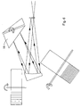
- FIG. 1 is a schematic representation of a particularly simple spectrometer arrangement, which is generally designated 10.
- the spectrometer assembly 10 includes an entrance slit 12, an off-axis paraboloid as Collimator mirror 14, a back mirrored prism 16 and an echelle grating 18.
- a detector 20 is provided for receiving the generated spectra.
- the roof edge of the prism 16 is perpendicular to the plane of representation.
- the grating lines of the echelle grating 18 run in the display plane.
- the spectrometer assembly 10 comprises, in addition to the above-mentioned optical components, further components, such as a housing, a base plate, fastening and adjustment means, mechanical drives and electrical components for controlling the optical components and for receiving and evaluating the signals at the detector 20, the simplicity here are not shown half.
- Radiation from a radiation source entering the spectrometer array 10 through the entrance slit 12 is represented by its marginal rays 22.
- the radiation 22 is collimated at the collimator mirror 14 to form a parallel bundle 24.
- the parallel bundle 24 strikes the prism 16 at an angle of incidence ⁇ , where it is dispersed in the plane of representation in a transverse dispersion direction.
- the bundle runs in prism 16 to the mirrored back 26. There it is reflected and runs back again through the prism.
- the angle of incidence ⁇ is chosen so that the incident beam 24 is well separated from the reflected beam 28.
- the reflected, parallel bundle 28 falls on the echelle grating 18. There it is dispersed in the main dispersion direction out of the display plane.
- the echelle grating 18 is positioned such that the radiation continues to travel back to the prism 16, displaced as a parallel bundle 30 by a very small angle. There it is again dispersed in the transverse dispersion direction, reflected and dispersed once more. The still parallel bundle 32 is then focused on the off-axis mirror 14, which this time forms the camera, in the exit plane with the detector 20.
- FIG. 11 shows an example of the thus generated two-dimensional intensity distribution of a line emitter in the exit plane of the spectrometer when illuminated with a single optical fiber.
- the orders 11, 13 etc. run vertically in the illustration. Several orders are next to each other.
- the distance 15 between the orders increases in accordance with the dispersion curve of the prism to the short-wave wavelength range (on the right in the illustration).
- a plurality of lines are spectrally separated. The separation takes place in the vertical direction in the representation.
- line radiators as is often the case with multi-element atomic emission spectroscopy, a configuration can be chosen that allows for order overlap as long as the individual lines do not overlap.
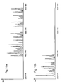
- FIG. 10 shows the course of intents plotted over the wavelength, which was generated by suitable evaluation. It can be seen that the lines are well separated according to the high resolution of the Echelle grating. The high intensity of the spectral lines is caused inter alia by the high light conductance of the arrangement. A comparison is in FIG. 9 shown.
- FIG. 9a Figure 4 shows a spectral line created using a prior art Echelle spectrometer arrangement. The gap height is substantially smaller in this line to avoid order overlap than in the same spectral line, which in FIG. 9b is shown.
- the spectral line in FIG. 9b corresponds to the intensity distribution when using the arrangement according to the invention in monochromator / Polychromator case with extremely large transverse dispersion and large Eitrittsspalt opening in both dimensions.
- the prism 16 is mounted on an about a perpendicular to the plane extending axis 36 rotatable table. This is in FIG. 1 shown.
- the axle 36 is driven by a controllable motor. By rotation of the prism 16, the orders can be moved in the transverse dispensing direction. Then, as an example in monochromator operation, a selected order can be detected on a detector line.
- the echelle grating 18 is rotatably mounted about an axis 38 parallel to the plane of representation. By rotating this axis by means of a controllable motor, a selected wavelength of a selected order can be shifted to a selected detector element.
- the described arrangement requires very few optical components. This allows the generation of a spectrum with low reflection and transmission losses.
- the arrangement is inexpensive and easy to adjust. Since almost all components are run through by a parallel bundle, the aberrations are very low. This increases the resolution of the device.
- the light conductance is increased by multiple transverse dispersion. This makes possible, in particular in the monochromator case, a large gap height in the transverse dispersion direction.
- the arrangement is also very compact and achieves high resolutions with small dimensions.
- FIG. 2 shows a further embodiment of the embodiment FIG. 1 ,
- the arrangement is basically the same structure as the embodiment described above.
- another prism 40 is mounted on the turntable.
- the roof edge of the prism 40 runs parallel to the roof edge of the prism 16.
- the prism 16 facing the rear side 42 of the additional prism 40 is also mirrored.
- the prism 40 has a smaller prism angle 44 than the prism 16. If the application now requires less lateral dispersion, the prism assembly with the prisms 16 and 40 on the turntable can be rotated about the axis 36 through an angle of about 180 °. Then the prism 40 is active.
- a smaller transverse dispersion is useful, for example, when measured in a region with shorter wavelengths, where the prism dispersion is particularly large. Then the orders are not pulled apart as the detector allows.
- a prism made of different materials with different transmission and refraction properties can also be used.
- FIGS. 3 to 5 show a further embodiment of the embodiments FIG. 1 and 2 , Regardless of whether one or two prisms are provided, another echelle grating 46 may be present which has other properties, such as a different line number or blaze angle. Again, the choice of echelle grating is made in accordance with the desired effect for the particular application.
- the selection of the echelle grating 18 or 46 is made by simple rotation of the prism.
- the representation in FIG. 3 shows the arrangement in which the prism prism with the large prism angle and the echelle grating 18 were selected.
- the representation in FIG. 4 shows the arrangement in which the prism with a smaller prism angle and the echelle grating 18 were selected.
- the representation in FIG. 5 shows the arrangement in which the prism prism with the smaller prism angle and the Echelle grating 46 were selected.
- FIG. 10 shows by way of example the effects of a change of Echelle grating.
- the echelle grating 18 has a smaller grating constant than the echelle grating 46. In the present exemplary embodiment, it is particularly well suited for the shortwave region below 400 nm.
- This echelle grating 18 is used with a comparatively large prism angle prism, as shown in FIG. 2 is shown.
- Calcium fluoride has a high transmission for the wavelength range below 400 nm.
- the large prism angle causes a high transverse dispersion.
- the arrangement off FIG. 2 is therefore optimized for the short-wave range, as shown in FIG. 10b is shown.
- FIG. 10a The schematically illustrated spectrum is generated by a configuration having a prism with a lower prism angle using a flint glass. This material is particularly suitable for the range above 400 nm. Such a configuration is in FIG. 4 and 5 shown.
- FIG. 6 and 7 show configurations that may be useful.
- the prism 16 or 46 is just adjusted so that the radiation does not fall on an echelle grating at all. Then only a linear overview spectrum of low resolution is generated at the detector.
- the radiation can be reflected back directly to the entrance slit ( FIG. 6 ) or in the direction of a plane mirror 48 (FIG. FIG. 7 ). The radiation is reflected back to the plane mirror 48 in autocollimation and re-runs across the prism 46.
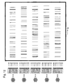
- FIG. 12 shows five spectra from different radiation sources.
- the corresponding spectra are in FIG. 13 shown.
- the high-resolution Echelle spectrometer with a two-dimensional intensity distribution can be switched to a low-resolution prism spectrometer with one-dimensional dispersion, with which an overview of the spectral intensity distribution of a radiation source can be obtained.
- the use of an area detector in the exit plane allows the unused dimension to be used for different purposes.
- the spectral intensity distribution of different light sources can preferably be compared by the use of light guides, as shown in FIG. 12 and 13
- the spatially resolved spectrum of a light source can also be measured.
- the detector elements can be binned over the gap height, whereby a particularly high light conductance is achieved.
Description
- Die Erfindung betrifft eine Spektrometeranordnung enthaltend:
- (a) eine Kollimatoroptik zur Erzeugung eines parallelen Strahlenbündels aus der in die Spektrometeranordnung eintretenden Strahlung,
- (b) eine Dispersionsanordnung zur Dispersion eines aus der in die Spektrometeranordnung eintretenden Strahlung erzeugten parallelen Strahlenbündels in einer Querdispersionsrichtung, und
- (c) ein Echelle-Gitter zur Dispersion der in die Spektrometeranordnung eintretenden Strahlung in einer Hauptdispersionsrichtung, wobei,
- (d) die Dispersionsanordnung (16; 40) reflektierend ausgebildet ist, und
- (e) die Dispensionsanordnung (16; 40) entlang des optischen Weges vor dem Echelle-Gitter (18; 46) derart angeordnet ist, dass das parallele Strahlenbündel in Richtung auf das Echelle-Gitter reflektiert wird.
- Die Erfindung betrifft ferner ein Verfahren zur spektralen Zerlegung von Strahlung, mit den Schritten:
- (a) Erzeugen eines parallelen Strahlenbündels mit einer Kollimatoroptik;
- (b) Dispergieren der Strahlung an einem Echelle-Gitter in einer Hauptdispersionsrichtung; und
- (c) Dispergieren der parallelen Strahlung an einer Dispersionsanordnung in einer Querdispersionsrichtung;
- (d) wobei das parallele Strahlenbündel (24) durch die Dispersionsanordnung (16; 40) in Richtung auf das Echelle-Gitter (18; 46) reflektiert wird.
- Bei einem Echelle-Spektrometer werden Gitter mit einem treppenartigen (Echelle (frz.) = Treppe) Querschnitt verwendet. Durch die stufenartige Struktur mit einem entsprechenden Blaze-Winkel wird ein Beugungsmuster erzeugt, welches die gebeugte Strahlung in hohen Ordnungen, z.B. in dreißigster bis einhundertster Ordnung konzentriert. Dadurch können hohe Werte für die Dispersion und das spektrale Auflösungsvermögen bei kompakter Anordnung erreicht werden. Die Ordnungen können sich - je nach einfallendem Wellenlängenbereich - überlagern. Die Ordnungen werden bei Echelle-Spektrometern mit interner Ordnungstrennung daher nochmals quer zur Dispersionsrichtung des Echelle-Gitters dispergiert, um die verschiedenen auftretenden Ordnungen in der Fokalfläche zu trennen. Man erhält so ein zweidimensionales Spektrum, das mit Flächendetektoren erfasst werden kann.
- Ein Echelle-Spektrometer mit interner Ordnungtrennung unterscheidet sich von Echelle-Spektrometern mit externer Ordnungstrennung dadurch, daß bei den letztgenannten das Echelle-Gitter nur mit Strahlung aus einem schmalen Wellenlängenbereich beaufschlagt wird.
- Bei Spektrometern mit interner Ordnungstrennung wird das Spektrum in Form einer zweidimensionalen Struktur auf dem Detektor erzeugt. Diese Struktur besteht im Wesentlichen aus parallel zueinander angeordneten, spektralen Abschnitten von jeweils der Größe eines freien Spektralbereichs des Echelle-Gitters. Die Verwendung eines Flächendetektors mit einer Vielzahl von Detektorelementen erlaubt die simultane Erfassung eines großen Wellenlängenbereichs mit hoher spektraler Auflösung (Spektrograph). Bei Verwendung des Spektrometers als Monochromator (Polychromator) wird Strahlung aus einem ausgewählten Wellenlängenbereich durch Drehung von Gitter und/oder Prisma auf einen Austrittsspalt oder einen Zeilendetektor im Bereich der Austrittsebene erfasst.
- Die Querdispersion wird gewöhnlich so groß gewählt, dass die Ordnungen überall vollständig getrennt sind. Um dies über den gesamten Spektralbereich zu gewährleisten, gibt es spektrale Bereiche, bei denen zwischen den einzelnen Ordnungen ein nicht genutzter Zwischenraum entsteht. So entstehen bei Verwendung eines Prismas zur Querdispersion im kurzwelligen Spektralbereich aufgrund des Dispersionsverlaufes größere Zwischenräume als im längerwelligen Spektralbereich. Bei Verwendung eines Beugungsgitters zur Querdispersion ist es umgekehrt.
-
DE 41 18 760 A1 offenbart einen Doppel-Echelle-Monochromator mit externer Ordnungstrennung. Das in den Monochromator eingestrahlte Licht wird über ein einen Konkavspiegel zu einem Prisma geleitet. Dort wird das Licht vordispergiert und im Wesentlichen in sich selbst in Richtung auf den Spiegel zurückgeleitet. Mit einem Zwischenspalt wird ein kleiner Spektralbereich ausgewählt, welcher in ein nachgeordnetes Echelle-Spektrometer eintritt. Über einen weiteren Konkavspiegel wird das Licht auf ein Echelle-Gitter geleitet. Die am Echelle-Gitter dispergierte Strahlung läuft ebenfalls im Wesentlichen in sich selbst zurück und wird mit einem geringen Winkel fast parallel zur einfallenden Strahlung auf einen Detektor reflektiert. Die Spiegel arbeiten bei der bekannten Anordnung in Autokollimation, d.h. der Kollimatorspiegel dient gleichzeitig als Kameraspiegel. -
DE 40 21 159 A1 offenbart einen Echelle-Polychromator, bei dem Strahlung an einem Echelle-Gitter in einer Hauptdispersionsrichtung dispergiert wird und an einem davor angeordneten Prisma in einer Querdispersionsrichtung dispergiert wird. Dadurch entsteht in der Austrittsebene ein zweidimensionales Spektrum mit einer Vielzahl an nebeneinanderliegenden Ordnungen. Zur Vermeidung von Ordnungsüberlappung müssen die Spalthöhe des Eintrittsspalts und damit der Lichtleitwert stark begrenzt werden. - Es sind Anordnungen bekannt, mit denen Strahlung mehrfach über ein Echelle-Gitter geleitet wird, um eine höhere Auflösung zu erreichen:
-
DE 199 61 908 C2 offenbart einen Echelle-Monochromator in Littrow-Anordnung ohne Ordnungstrennung. Die durch einen Eintrittsspalt in den Monochromator eintretende Strahlung wird über einen Kollimatorspiegel auf ein Echelle-Gitter gelenk. Das Echelle-Gitter arbeitet in zwei Stellungen. In der ersten Stellung läuft die dispergierte Strahlung in Autokollimation zurück über den Spiegel zum Austrittsspalt. In der zweiten Stellung läuft die dispergierte Strahlung auf einen Planspiegel und wird von dort zurück auf das Echelle-Gitter reflektiert. Dort wird die Strahlung, ein weiteres Mal dispergiert und läuft dann erst in Autokollimation über den Spiegel zurück zum Detektor. -
DE 103 47 862 B4 offenbart ein Echelle-Spektrometer, bei dem die an einem Echelle-Gitter dispergierte Strahlung unter einem kleinen Winkel zurück in Richtung des Eintrittsspalts geleitet wird. Eine Planspiegelanordnung, welche um den Eintrittsspalt herum angeordnet ist, lenkt die dispergierte Strahlung erneut zum Echelle-Gitter, so dass die Strahlung ein weiteres Mal dispergiert wird. - Bei den bekannten Echelle-Spektrometern in Autokollimations-Anordnungen wird die Strahlung entweder mehrfach über das Echelle-Gitter geführt, um das theoretische Auflösungsvermögen und die Winkeldispersion zu erhöhen oder es werden Prismen in Autokollimation benutzt, um durch die damit verbundene Faltung des Strahlengangs kompakte Anordnungen zu erreichen. Nachteilig ist dabei, dass der Lichtleitwert dieser Spektrometer bei Anordnungen mit interner Ordnungstrennung durch die geringe Spalthöhe stark eingeschränkt ist. Die geringste Ordnungstrennung im gesamten Spektralbereich bestimmt dabei den maximalen Wert für die zulässige Spalthöhe. Gegenüber Spektrometern mit Beugungsgittern in erster Ordnung entsteht ein typischer Verlust an Lichtleitwert um den Faktor 10 bis 50.
- Es ist Aufgabe der Erfindung, ein kompaktes Spektrometer der eingangs genannten Art mit hoher Auflösung bei besonders hohem Lichtleitwert zu schaffen. Erfingdungsgemäß wird die Aufgabe dadurch gelöst, dass die Dispersionsanordnung reflektierend ausgebildet ist, und die Dispersionsanordnung in Bezug auf das Echelle-Gitter derart angeordnet ist, dass das parallele Strahlenbündel in Richtung auf das Echelle-Gitter reflektiert wird und die Dispersionsanordnung ein weiteres Mal durchläuft, und der abbildende Spiegel das reflektierte und dispergierte parallele Strahlenbündel fokussiert. Die Dispersionsanordnung kann beispielsweise von einer Anordnung mit einem Prisma gebildet sein, welches die Strahlung in Querdispersionsrichtung spektral zerlegt. Eine solche Prismenanordnung kann ein rückseitig verspiegeltes Prisma umfassen. Die Prismenanordnung kann aber auch ein Transmissionsprisma umfassen, hinter dem ein Planspiegel, ein reflektierendes Gitter oder ein weiteres rückseitig verspiegeltes Prisma angeordnet ist. Die Dispersionsanordnung kann statt einer Prismenanordnung eine Gitteranordnung oder eine Kombination aus Gitter und Prisma, ein sogenanntes Grism umfassen.
- Bei einer solchen Anordnung kann die Strahlung durch einen Eintrittsspalt geleitet werden. Die divergente Strahlung trifft auf eine Kollimatoroptik, beispielsweise in Form einer achromatischen Linsenoptik oder eines Hohlspiegels. Ein solcher Spiegel kann ein off-axis Paraboloid, ein Toroid oder ein sphärischer Spiegel sein. Ein off-axis Paraboloid wird bevorzugt. An der Kollimatoroptik wird ein paralleles Strahlenbündel erzeugt. Dieses parallele Strahlenbündel wird auf eine reflektierende Dispersionsanordnung geleitet. Im einfachsten Fall ist eine solche Dispersionsanordnung ein rückseitig verspiegeltes Prisma. Das Prisma ist so angeordnet, dass die reflektierte und dispergierte Strahlung nicht in sich selbst zurückläuft, sondern unter einem Winkel in Richtung eines Echelle-Gitters gelenkt wird. Das Echelle-Gitter ist so angeordnet, dass es die Strahlung in einer anderen Richtung, der Hauptdispersionsrichtung, dispergiert. Die Hauptdispersionsrichtung kann insbesondere senkrecht zur Querdispersionsrichtung verlaufen. Dann entsteht ein zweidimensionales Spektrum in der Austrittsebene.
- Wenn das Echelle-Gitter um eine Achse drehbar gelagert ist, die parallel zu den Gitterfurchen verläuft, kann eine ausgewählte Wellenlänge oder ein ausgewählter Wellenlängenbereich auf einen Austrittsspalt oder einen Detektor in der Austrittsebene gelenkt werden. Das Prisma kann um eine Achse drehbar gelagert sein, die parallel zur brechenden Kante verläuft. Dann können ausgewählte Ordnungen auf einen Austrittsspalt oder einen Detektor in der Austrittsebene gelenkt werden.
- Der doppelte Durchgang am Prisma erlaubt die Erzeugung einer hohen Dispersion und damit großen Ordnungstrennung. Dies führt dazu, dass ein hoher Eintrittsspalt verwirklicht werden kann. Die Anordnung hat daher einen vergleichsweise hohen Lichtleitwert bei hoher Auflösung und nur wenigen optischen Komponenten.
- Bei der Anordnung ist das Echelle-Gitter derart angeordnet, dass die dispergierte Strahlung zurück in Richtung auf die Dispersionsanordnung reflektiert wird. Die Anordnung arbeitet dann in Autokollimation. Unter einer Autokollimationsanordnung wird eine Anordnung verstanden, bei welcher die Kollimatoroptik gleichzeitig die Funktion der Kameraoptik übernimmt, indem der Strahl im Wesentlichen in sich selbst zurück reflektiert wird. Das vom Echelle-Gitter zurücklaufende, parallele Strahlenbündel durchläuft die Dispersionsanordnung ein weiteres Mal. Die dort erneut in Querdispersionsrichtung dispergierte Strahlung läuft zurück zur Autokollimationsoptik. Dort wird der Strahl in der Austrittsebene fokussiert.
- Die Strahlung wird bei dieser Anordnung in Querdispersionsrichtung mehrfach dispergiert. Entsprechend werden die Ordnungen des Echelle-Spektrums besonders weit auseinandergezogen. Die ansonsten stark begrenzte Spalthöhe kann so sehr groß gewählt werden. Es wird ein Minimum an optischen Bauelementen benötigt. Das benötigte Materialvolumen des Prismas ist bei der Reflexionsanordnung und bei doppeltem Durchgang gegenüber einer Transmissionsanordnung um einen Faktor 4 verringert. Dies führt zu einer wesentlichen Kosteneinsparung insbesondere bei teuren, schlierenfreien Kristallmaterialien.
- Die Dispersionsanordnung dient neben der Dispersion auch zur Trennung des einfallenden von dem reflektierten, parallelen Strahlbündel. Anders als bei bekannten Autokollimationsanordnungen läuft die Strahlung an dieser Dispersionsanordnung nicht in sich selbst zurück, sondern zunächst zum Echelle-Gitter. In einer besonders vorteilhaften Anordnung entsteht eine besonders hohe Abbildungsqualität, weil das Prisma in seiner Hauptebene ablenkt und dispergiert. Sie erfordert zudem nur wenige optische Bauteile, mit entsprechend geringen Transmissions- und Reflexionsverlusten. Durch Drehung um nur zwei Achsen kann das Spektrum unter Einhaltung optimaler Abbildungsbedingungen in die Bildebene fokussiert und positioniert werden. Dadurch wird die Anordnung leicht zu justieren und ist kostengünstig in der Herstellung.
- Es versteht sich, dass die Reflexion an dem Echelle-Gitter direkt zurück zur Dispersionsanordnung erfolgen kann. Alternativ kann die Strahlung auch indirekt zunächst auf einen Spiegel, dann erneut über das Echelle-Gitter und erst dann zurück zur Dispersionsanordnung laufen.
- In einer Ausgestaltung der Erfindung ist ein weiteres Echelle-Gitter vorgesehen und die Dispersionsanordnung ist von einer ersten in eine zweite Stellung bewegbar, denen jeweils ein Echelle-Gitter zugeordnet ist, in dessen Richtung die Strahlung reflektiert wird. Über eine einfache Drehung an der Dispersionsanordnung kann beispielsweise eines von zwei Echelle-Gittern ausgewählt werden. Jedes der Echelle-Gitter kann bezüglich seiner Dispersionseigenschaften an den jeweiligen Anwendungsfall angepasst sein. Es versteht sich, dass auch ein drittes oder weitere Echelle-Gitter vorgesehen sein können. Dann ist die Dispersionsanordnung in eine dritte oder weitere Stellungen bewegbar. Anstelle eines der beiden Echelle-Gitter kann auch ein Planspiegel vorgesehen sein. Bei entsprechender Drehung und Beleuchtung des Planspiegels wird auf dem Detektor ein eindimensionales Spektrum erzeugt. Dieses kann als Übersichtsspektrum dienen, wobei nach Drehung der Dispersionsanordnung bei Beleuchtung des Echelle-Gitters nachfolgend zweidimensionale Spektren mit hoher Auflösung abgebildet werden. Bei Verwendung eines Flächendetektors kann dabei das zweidimensionale Spektrum simultan ausgelesen werden. Die zweite Dimension des Flächendetektors kann im Falle der Beleuchtung des Planspiegels zur simultanen Registrierung der eindimensionalen Spektren verschiedener Strahlungsquellen oder zur ortsaufgelösten spektralen Messung einer Strahlungsquelle benutzt werden. Dieses ist auch bei Drehung der Dispersionseinrichtung der Fall, wenn die Strahlung von der Dispersionseinrichtung direkt zum Autokollimationsoptik zurück reflektiert und dispergiert wird.
- Wenn das Echelle-Gitter drehbar angeordnet ist, kann ein weiteres Echelle-Gitter auf dessen Rückseite vorgesehen sein. Das weitere Echelle-Gitter kann unterschiedliche Eigenschaften, etwa eine unterschiedliche Strichzahl aufweisen. Statt Drehung des Prismas oder zusätzlich dazu kann auch das Echelle-Gitter um einen Winkel von beispielsweise 180° gedreht werden. Dann kommt das weitere Echelle-Gitter zum Einsatz.
- In einer weiteren Ausgestaltung der Erfindung umfasst die Dispersionsanordnung ein auf der Rückseite verspiegeltes Prisma, das zusammen mit einem weiteren, auf der Rückseite verspiegelten Prisma auf einem Drehtisch montiert ist, so dass durch Drehen des Drehtisches eines der beiden Prismen auswählbar ist. Auf diese Weise kann durch Drehung des Drehtisches die Querdispersion ausgewählt werden. So können Prismen aus unterschiedlichem Material eingesetzt werden, welche unterschiedliche Wellenlängenabhängigkeit der Dispersion haben. Es können auch Prismen mit unterschiedlichem Prismenwinkel eingesetzt werden. Es können auch weitere reflektierend ausgebildete Dispersionsanordnungen wie Beugungsgitter oder Grisms in Kombination mit dem Prisma auf dem Drehtisch montiert sein. Die Drehachse dient dabei sowohl zur Auswahl der jeweiligen Querdispersionsanordnung, eines Echelle-Gitters oder eines Planspiegels als auch der Feinjustage des Spektrums auf dem Detektor.
- In einer weiteren Ausgestaltung der Erfindung kann ein weiteres Prisma im Strahlengang angeordnet sein. Ein solches Prisma kann beispielsweise dazu dienen, den spektralen Verlauf der Querdispersion zusätzlich zu beeinflussen. Das weitere Prisma kann insbesondere zwischen der Dispersionsanordnung und dem Echelle-Gitter angeordnet sein.
- Die Strahlung an der Dispersionsanordnung kann um einen geringen Winkel aus der Hauptebene heraus abgelenkt werden. Dann läuft der Strahl aus der Hauptebene heraus, so dass ein Detektor in der Austrittsebene oberhalb oder unterhalb eines Eintrittsspaltes angeordnet werden kann. Dabei werden die Strahlen des doppelten Durchgangs durch die Dispersionseinrichtung von den Strahlen des direkt reflektierten, einfachen Durchgangs in der Fokalfläche getrennt. Diese Anordnung dient dann vorzugsweise der Unterdrückung von Falsch- und Streulicht.
- In einer besonderen Ausgestaltung der Anordnung befindet sich ein ortsauflösender Flächendetektor, z.B. ein CCD-Detektor, in der Fokalfläche. Im diesem Fall ist die Anordnung vorzugsweise ein hochauflösender Spektrograph. In einer zweiten Ausgestaltung befindet sich ein Zeilendetektor, oder auch ein Einzeldetektor, z.B. eine Fotodiode oder ein Sekundärelektronenvervielfacher (Fotomultiplier) in der Fokalebene. Im diesem Fall ist die Anordnung ein lichtstarker Monochromator. Je nach Eintrittsspaltbreite ist das apparatebedingte Auflösungsvermögen innerhalb weiter Grenzen einstellbar.
- Bei einem erfindungsgemäßen Verfahren zur spektralen Zerlegung von Strahlung der eingangs genannten Art wird das parallele Strahlenbündel durch die Dispersionsanordnung in Richtung auf das Echelle-Gitter reflektiert und durchläuft die Dispersionsanordnung ein weiteres Mal, und die dispergierte und reflektierte Strahlung wird mit der gleichen Kollimatoroptik fokussiert. Dabei kann die dispergierte Strahlung vom Echelle-Gitter zurück in Richtung auf die Dispersionsanordnung reflektiert werden.
- Die erfindungsgemäße Anordnung schafft in einer bevorzugten Ausgestaltung der Erfindung bei Beleuchtung mit einem Kontinuumsstrahler eine schmalbandige intensive monochromatische Lichtquelle mit extrem hohem Lichtleitwert. Die Verwendung einer solchen Anordnung aus Kontinuumsstrahler und Spektrometer ermöglicht die Durchstimmbarkeit über den gesamten Wellenlängenbereich ohne Wechsel der Lichtquelle.
- Eine vorteilhafte Ausgestaltung der Erfindung ist die Verwendung der eingangs genannten Anordnung für die Analyse im VUV-Bereich. Dies wird begünstigt durch die geringe Größe des zu evakuierenden Volumens und minimale verluste bei wenig Reflexionen und hoher Transmission.
- Zur Unterdrückung von parasitären Reflexionen am Littrow-Prisma können die Parameter Prismenmaterial und Ablenkwinkel verwendet werden. Diese werden so ausgewählt, dass Falschlicht nicht auf den Detektor gelangt.
- Ausgestaltungen der Erfindung sind Gegenstand der Unteransprüche. Ein Ausführungsbeispiel ist nachstehend unter Bezugnahme auf die beigefügten Beispiele näher erläutert.
-
- Fig.1
- zeigt eine Spektrometeranordnung mit einem Echelle-Gitter und einem reflektierende Prisma, welches parallele Strahlung in Richtung auf das Echelle-Gitter reflektiert.
- Fig.2
- zeigt die Spektrometeranordnung aus
Figur 1 , bei welcher ein zusätzliches Prisma mit kleinerem Prismenwinkel als reflektierendes Prisma eingesetzt werden kann. - Fig.3
- zeigt eine Spektrometeranordnung, bei welcher zwischen zwei Echelle-Gittern und zwei Prismen ausgewählt werden kann.
- Fig.4
- zeigt die Spektrometeranordnung aus
Figur 3 , bei welcher das zweite Prisma eingesetzt wird. - Fig.5
- zeigt die Spektrometeranordnung aus
Figur 3 , bei welcher das zweite Echelle-Gitter eingesetzt wird. - Fig.6
- zeigt die Spektrometeranordnung aus
Figur 3 , bei welcher sich das Prisma in eine Autokollimationsposition ohne Einsatz eines Echelle-Gitters befindet. - Fig.7
- zeigt die Spektrometeranordnung ohne Einsatz eines Echelle-Gitters analog zu
Figur 6 , bei dem die Strahlung mittels eines Planspiegels erneut über das Prisma geleitet wird. - Fig.8
- zeigt die Spektrometeranordnung mit Prisma und Echelle-Gitter analog zu
Figur 3 , wobei ein zusätzliches Transmissionsprisma im Strahlengang zwischen dem Prisma und dem Echelle-Gitter angeordnet ist. - Fig.9a-b
- zeigen die spektrale Intensitätsverteilung einer Emissionslinie geringer Bandbreite bei etwa 500 nm für die erfindungsgemäße Anordnung für den Fall einer hohen spektralen Auflösung bei kleinem Eintrittsspalt.
- Fig.10a-b
- illustrieren die Auswirkungen für den Fall eines hohen Lichtleitwertes bei großem Eintrittsspalt.
- Fig.11
- veranschaulicht qualitativ die simultan gemessene Intensitätsverteilung eines Linienspektrums auf einem Flächendetektor für eine Spektrometeranordnung entsprechend den
Figuren 1-5 und8 für eine Lichtquelle. - Fig.12
- veranschaulicht qualitativ die simultan gemessene Intensitätsverteilung eines Linienspektrums auf einem Flächendetektor für eine Spektrometeranordnung entsprechend den
Figuren 6 oder7 . - Fig.13
- zeigt die simultan gemessene spektrale Intensitätsverteilung von beispielhaften Linienspektren, die von fünf unterschiedlichen Lichtquellen emittiert werden.
-
Figur 1 . ist eine schematische Darstellung einer besonders einfachen Spektrometeranordnung, die allgemein mit 10 bezeichnet ist. Die Spektrometeranordnung 10 umfasst einen Eintrittsspalt 12, einen off-axis-Paraboloid als Kollimatorspiegel 14, ein rückseitig verspiegeltes Prisma 16 und ein Echelle-Gitter 18. In der Austrittsebene der Spektrometeranordnung 10 ist ein Detektor 20 zur Aufnahme der erzeugten Spektren vorgesehen. Die Dachkante des Prismas 16 verläuft senkrecht zur Darstellungsebene. Die Gitterstriche des Echelle-Gitters 18 verlaufen in der Darstellungsebene. - Die Spektrometeranordnung 10 umfasst neben den oben genannten optischen Bauteilen weitere Komponenten, wie ein Gehäuse, eine Grundplatte, Befestigungs- und Justagemittel, mechanische Antriebe und elektrische Komponenten zur Steuerung der optischen Bauteile und zur Aufnahme und Auswertung der Signale am Detektor 20, die hier der Einfachheit halber nicht dargestellt sind.
- Strahlung aus einer Strahlungsquelle, welche durch den Eintrittsspalt 12 in die Spektrometeranordnung 10 eintritt, ist durch ihre Randstrahlen 22 repräsentiert. Die Strahlung 22 wird am Kollimatorspiegel 14 zu einem parallelen Bündel 24 kollimiert. Das parallele Bündel 24 trifft unter einem Einfallswinkel α auf das Prisma 16 und wird dort in der Darstellungsebene in einer Querdispersionsrichtung dispergiert. Das Bündel läuft im Prisma 16 bis zur verspiegelten Rückseite 26. Dort wird es reflektiert und läuft zurück erneut durch das Prisma. Der Einfallswinkel α ist so gewählt, dass das einfallende Bündel 24 von dem reflektierten Bündel 28 gut getrennt ist. Das reflektierte, parallele Bündel 28 fällt auf das Echelle-Gitter 18. Dort wird es in Hauptdispersionsrichtung aus der Darstellungsebene heraus dispergiert.
- Das Echelle-Gitter 18 ist derart positioniert, dass die Strahlung, weiterhin als paralleles Bündel 30 um einen sehr geringen Winkel versetzt zurück zum Prisma 16 läuft. Dort wird es erneut in Querdispersionsrichtung dispergiert, reflektiert und ein weiteres Mal dispergiert. Das weiterhin parallele Bündel 32 wird anschließend am off-axis-Spiegel 14, der diesmal die Kamera bildet, in der Austrittsebene mit dem Detektor 20 fokussiert.
- In der Austrittsebene verlaufen die vom Echelle-Gitter erzeugten Ordnungen senkrecht zur Darstellungsebene. Durch die Querdispersion am Prisma 16 haben diese einen vergleichsweise großen Abstand zueinander, so dass die Eintrittsspalthöhe in Querdispersionsrichtung - in
Figur 1 entspricht dies der Breite in der Darstellungsebene-ebenfalls vergleichsweise groß gewählt werden kann, ohne dass die Ordnungen überlappen. Auf diese Weise kann ein besonders hoher Lichtleitwert realisiert werden.Figur 11 zeigt ein Beispiel für die so erzeugte zweidimensionale Intensitätsverteilung eines Linienstrahlers in der Austrittsebene des Spektrometers bei Beleuchtung mit einer Einzel-Lichtleitfaser. Die Ordnungen 11, 13 etc. verlaufen senkrecht in der Darstellung. Mehrere Ordnungen liegen nebeneinander. Der Abstand 15 zwischen den Ordnungen nimmt entsprechend des Dispersionsverlaufs des Prismas zum kurzwelligen Wellenlängenbereich (rechts in der Darstellung) hin zu. Innerhalb jeder Ordnung sind eine Vielzahl von Linien spektral getrennt. Die Trennung erfolgt in vertikaler Richtung in der Darstellung. Bei Linienstrahlern, wie dies bei Multielement-Atomemissionsspektroskopie häufig der Fall ist, kann eine Konfiguration gewählt werden, die einen Ordnungsüberlapp erlaubt, solange die einzelnen Linien nicht überlappen. - Jedem Ort x,y in der Austrittsebene entspricht eine Wellenlänge.
Figur 10 zeigt den Intentsitätsverlauf aufgetragen über die Wellenlänge, der durch geeignete Auswertung erzeugt wurde. Man erkennt, dass die Linien entsprechend der hohen Auflösung des Echelle-Gitters gut voneinander getrennt sind. Die hohe Intensität der Spektrallinien wird unter anderem durch den hohen Lichtleitwert der Anordnung bewirkt. Ein Vergleich ist inFigur 9 dargestellt.Figur 9a zeigt eine Spektrallinie, die mit einer Echelle-Spektrometeranordnung nach dem Stand der Technik erzeugt wurde. Die Spalthöhe ist bei dieser Linie zur Vermeidung von Ordnungsüberlapp wesentlich kleiner als bei der gleichen Spektrallinie, die inFigur 9b dargestellt ist. Die Spektrallinie inFigur 9b entspricht der Intensitätsverteilung bei Verwendung der erfindungsgemäßen Anordnung im Monochromator/Polychromator-Fall bei extrem großer Querdispersion und großer Eitrittsspalt-Öffnung in beiden Dimensionen. - Das Prisma 16 ist auf einem um eine senkrecht zur Darstellungsebene verlaufende Achse 36 drehbaren Tisch montiert. Dies ist in
Figur 1 dargestellt. Die Achse 36 wird von einem ansteuerbaren Motor angetrieben. Durch Drehung des Prismas 16 können die Ordnungen in Querdispensionsrichtung verschoben werden. Dann kann als Beispiel im Monochromatorbetrieb eine ausgewählte Ordnung auf einer Detekterzeile detektiert werden. - Das Echelle-Gitter 18 ist um eine Achse 38 parallel zur Darstellungsebene drehbar gelagert. Durch Drehung dieser Achse mittels eines ansteuerbaren Motors kann eine ausgewählte Wellenlänge einer ausgewählten Ordung auf ein ausgewähltes Detektorelement verschoben werden.
- Die beschriebene Anordnung erfordert nur sehr wenige optische Bauteile. Dies ermöglicht die Erzeugung eines Spektrums mit geringen Reflexions- und Transmissionsverlusten. Die Anordnung ist kostengünstig und leicht zu justieren. Da fast alle Bauteile von einem parallelen Bündel durchlaufen werden, sind die Abbildungsfehler sehr gering. Das erhöht das Auflösungsvermögen der Anordnung. Zusätzlich zu den geringen Verlusten an den Bauteilen und den geringen Abbildungsfehlern wird der Lichtleitwert erhöht, indem mehrfach querdispergiert wird. Dies ermöglicht insbesondere im Monochromator-Fall eine große Spalthöhe in Querdispersionsrichtung. Die Anordnung ist zudem besonders kompakt und erreicht hohe Auflösungen bei geringen Abmessungen.
-
Figur 2 zeigt eine weitere Ausgestaltung des Ausführungsbeispiels ausFigur 1 . Die Anordnung ist prinzipiell gleich aufgebaut, wie das oben beschriebene Ausführungsbeispiel. Zusätzlich zum Prisma 16 ist ein weiteres Prisma 40 auf dem Drehtisch montiert. Die Dachkante des Prismas 40 verläuft parallel zur Dachkante des Prismas 16. Die dem Prisma 16 zugewandte Rückseite 42 des zusätzlichen Prismas 40 ist ebenfalls verspiegelt. Das Prisma 40 hat einen kleineren Prismenwinkel 44 als das Prisma 16. Wenn die Anwendung nun eine geringere Querdispersion erfordert, kann die Prismenanordnung mit den Prismen 16 und 40 auf dem Drehtisch um die Achse 36 um einen Winkel von etwa 180° gedreht werden. Dann ist das Prisma 40 aktiv. Eine kleinere Querdispersion ist beispielsweise sinnvoll, wenn in einem Bereich mit kürzeren Wellenlängen gemessen wird, wo die Prismendispersion besonders groß ist. Dann werden die Ordnungen nicht weiter auseinandergezogen als der Detektor es zulässt. Statt eines unterschiedlichen Prismenwinkels kann je nach Anwendung auch ein Prisma aus unterschiedlichem Material mit anderen Transmissions- und Brechungseigenschaften verwendet werden. -
Figuren 3 bis 5 zeigen eine weitere Ausgestaltung der Ausführungsbeispiele ausFigur 1 und2 . Unabhängig davon, ob ein oder zwei Prismen vorgesehen sind, kann ein weiteres Echelle-Gitter 46 vorgegehen sein, das andere Eigenschaften, beispielsweise eine andere Strichzahl oder einen anderen Blaze-Winkel aufweist. Auch hier erfolgt die Auswahl des Echelle-Gitters nach Maßgabe des gewünschten Effektes für die jeweilige Anwendung. Die Auswahl des Echelle-Gitters 18 oder 46 erfolgt durch einfache Drehung des Prismas. Die Darstellung inFigur 3 zeigt die Anordnung, bei welcher das Prisma mit dem großen Prismenwinkel und das Echelle-Gitter 18 ausgewählt wurden. Die Darstellung inFigur 4 zeigt die Anordnung, bei welcher das Prisma mit einem kleineren Prismenwinkel und das Echelle-Gitter 18 ausgewählt wurden. Die Darstellung inFigur 5 zeigt die Anordnung, bei welcher das Prisma mit dem kleineren Prismenwinkel und das Echelle-Gitter 46 ausgewählt wurden. -
Figur 10 zeigt beispielhaft die Auswirkungen eines Wechsels des Echelle-Gitters. Das Echelle-Gitter 18 hat eine geringere Gitterkonstante als das Echelle-Gitter 46. Es ist im vorliegenden Ausführungsbeispiel besonders gut für den kurzwelligen Bereich unterhalb von 400 nm geeignet. Dieses Echelle-Gitter 18 wird mit einem Prisma aus mit vergleichsweise großem Prismenwinkel verwendet, wie dies inFigur 2 dargestellt ist. Kalziumfluorid besitzt für den Wellenlängenbereich unterhalb von 400 nm eine hohe Transmission. Der große Prismenwinkel bewirkt eine hohe Querdispersion. Die Anordnung ausFigur 2 ist daher für den kurzwelligen Bereich optimiert, wie dies inFigur 10b dargestellt ist. Das inFigur 10a schematisch dargestellte Spektrum wird durch eine Konfiguration erzeugt, die ein Prisma mit einem geringeren Prismenwinkel bei Verwendung eines Flintglases aufweist. Dieses Material ist für den Bereich oberhalb 400 nm besonders geeignet. Eine solche Konfiguration ist inFigur 4 und5 dargestellt. -
Figur 6 und7 zeigen Konfigurationen, welche zusätzlich sinnvoll sein können. Das Prisma 16 bzw. 46 wird gerade so eingestellt, dass die Strahlung überhaupt nicht auf ein Echelle-Gitter fällt. Dann wird am Detektor lediglich ein lineares Übersichtsspektrum geringer Auflösung erzeugt. Je nach gewünschter Dispersion, kann die Strahlung direkt zum Eintrittsspalt zurückreflektiert werden (Figur 6 ) oder in Richtung auf einen Planspiegel 48 (Figur 7 ). Die Strahlung wird an dem Planspiegel 48 in Autokollimation zurückreflektiert und läuft erneut über das Prisma 46. - Mit den Anordnungen aus
Figur 6 und7 wird eine eindimensionale Intensitätsverteilung erzeugt, wie es beispielhaft inFigur 12 dargestellt ist.Figur 12 zeigt fünf Spektren aus unterschiedlichen Strahlungsquellen. Die zugehörigen Spektren sind inFigur 13 dargestellt. Man erkennt, dass sich das hochauflösende Echelle-Spektrometer mit einer zweidimensionalen Intensitätsverteilung in ein niedrig-auflösendes Prismenspektrometer mit eindimensionaler Dispersion umschalten lässt, mit dem eine Übersicht über die spektrale Intensitätsverteilung einer Strahlungsquelle erhalten werden kann. Die Verwendung eines Flächendetektors in der Austrittsebene erlaubt die Nutzung der nichtverwendeten Dimension für verschiedene Zwecke. So kann die spektrale Intensitätsverteilung unterschiedlicher Lichtquellen vorzugsweise durch die Verwendung von Lichtleitern verglichen werden, wie dies inFigur 12 und13 angedeutet ist Es können aber auch das ortsaufgelöste Spektrum einer Lichtquelle gemessen werden. Schließlich können die Detektorelemente über die Spalthöhe gebinnt werden, wodurch ein besonders hoher Lichtleitwert erreicht wird. - Die Variationsvielfalt der Anordnung mit zwei oder mehreren Echelle-Gittern und verschiedenen Prismen erschließt sich dem Fachmann, ohne dass hier alle Variationen dargestellt werden müssen. Es ist ein wesentliches Merkmal aller Konfigurationen, dass diese durch bloße Drehung des Prismentisches um die Achse 36 erreichbar sind. Ein aufwändiges Austauschen von Komponenten und Translationsbewegungen sind nicht erforderlich. In jedem Fall wird eine besonders hohe Abbildungsqualität bei hohem Lichtleitwert und hoher Auflösung sowie geringen Kosten und Baumaßen erreicht. Es sind aber in bestimmten Anwendungsfällen auch weitere parallel zur Achse 36 verlaufende Achsen zur Drehung einzelner Komponenten der Dispersionsanordnung möglich und sinnvoll.
Claims (6)
- Spektrometeranordnung (10) enthaltend:(a) eine Kollimatoroptik zur Erzeugung eines parallelen Strahlenbündels aus der in die Spektrometeranordnung eintretenden Strahlung,(b) eine Dispersionsanordnung (16; 40) zur Dispersion eines aus der in die Spektrometeranordnung eintretenden Strahlung erzeugten parallelen Strahlenbündels in einer Querdispersionsrichtung,(c) ein Echelle-Gitter (18; 46) zur Dispersion der in die Spektrometeranordnung (10) eintretenden Strahlung in einer Hauptdispersionsrichtung, und
wobei(d) die Dispersionsanordnung (16; 40) reflektierend ausgebildet ist, und(e) die Dispersionsanordnung (16; 40) entlang des optischen Weges vor dem Echelle-Gitter (18; 46) derart angeordnet ist, dass das parallele Strahlenbündel in Richtung auf das Echelle-Gitter reflektiert wird
dadurch gekennzeichnet, dass(f) das Echelle-Gitter (18; 46) derart angeordnet ist, dass die dispergierte Strahlung zurück in Richtung auf die Dispersionsanordnung (16; 40) reflektiert wird und die Dispersionsanordnung ein weiteres Mal durchläuft, und(g) die Kollimatoroptik das reflektierte und dispergierte parallele Strahlenbündel fokussiert. - Spektrometeranordnung (10) nach einem der vorgehenden Ansprüche, dadurch gekennzeichnet, dass ein weiteres Echelle-Gitter (46) vorgesehen ist und die Dispersionsanordnung (16; 40) von einer ersten in eine zweite Stellung bewegbar ist, denen jeweils ein Echelle-Gitter (18; 46) zugeordnet ist, in dessen Richtung die Strahlung reflektiert wird.
- Spektrometeranordnung (10) nach einem der vorgehenden Anspruch, dadurch gekennzeichnet, dass die Dispersionsanordnung (16; 40) ein auf der Rückseite verspiegeltes Prisma (16) umfasst, das zusammen mit mindestens einem weiteren, auf der Rückseite verspiegelten Prisma (40) auf einem Drehtisch montiert ist, so dass durch Drehen des Drehtisches eines der Prismen auswählbar ist.
- Spektrometeranordnung (10) nach einem der vorgehenden Ansprüche, dadurch gekennzeichnet, dass zusätzlich zur Dispersionsanordnung (16; 40) ein Prisma im Strahlengang angeordnet ist.
- Spektrometeranordnung (10) nach einem der vorgehenden Ansprüche, dadurch gekennzeichnet, dass die Strahlung um einen geringen Winkel aus der Hauptebene heraus abgelenkt wird.
- Verfahren zur spektralen Zerlegung von Strahlung, mit den Schritten:(a) Erzeugen eines parallelen Strahlenbündels (24) mit einer Kollimatoroptik;(b) Dispergieren der Strahlung an einem Echelle-Gitter (18; 46) in einer Hauptdispersionsrichtung; und(c) Dispergieren der parallelen Strahlung an einer Dispersionsanordnung (16; 40) in einer Querdispersionsrichtung;(d) wobei das parallele Strahlenbündel (24) durch die Dispersionsanordnung (16; 40) in Richtung auf das Echelle-Gitter (18; 46) reflektiert wird und die Dispersionsanordnung ein weiteres Mal durchläuft,
dadurch gekennzeichnet, dass(e) die dispergierte Strahlung (28) vom Echelle-Gitter (18; 46) zurück in Richtung auf die Dispersionsanordnung (16; 40) reflektiert wird, und(f) die dispergierte und reflektierte Strahlung mit der gleichen Kollimatoroptik fokussiert wird.
Applications Claiming Priority (2)
| Application Number | Priority Date | Filing Date | Title |
|---|---|---|---|
| DE200910059280 DE102009059280A1 (de) | 2009-12-22 | 2009-12-22 | Spektrometeranordnung |
| PCT/EP2010/069472 WO2011076598A1 (de) | 2009-12-22 | 2010-12-13 | Spektrometeranordnung |
Publications (2)
| Publication Number | Publication Date |
|---|---|
| EP2516975A1 EP2516975A1 (de) | 2012-10-31 |
| EP2516975B1 true EP2516975B1 (de) | 2013-10-16 |
Family
ID=43759843
Family Applications (1)
| Application Number | Title | Priority Date | Filing Date |
|---|---|---|---|
| EP10801399.6A Active EP2516975B1 (de) | 2009-12-22 | 2010-12-13 | Spektrometeranordnung |
Country Status (5)
| Country | Link |
|---|---|
| US (1) | US8873048B2 (de) |
| EP (1) | EP2516975B1 (de) |
| CN (1) | CN102656431B (de) |
| DE (1) | DE102009059280A1 (de) |
| WO (1) | WO2011076598A1 (de) |
Cited By (1)
| Publication number | Priority date | Publication date | Assignee | Title |
|---|---|---|---|---|
| DE102016124980A1 (de) | 2016-01-14 | 2017-08-03 | Analytik Jena Ag | Spektrometer mit Zweidimensionalem Spektrum |
Families Citing this family (13)
| Publication number | Priority date | Publication date | Assignee | Title |
|---|---|---|---|---|
| DE102009059280A1 (de) | 2009-12-22 | 2011-06-30 | Leibniz-Institut für Analytische Wissenschaften-ISAS-e.V., 44139 | Spektrometeranordnung |
| US9395245B2 (en) * | 2013-03-15 | 2016-07-19 | Westco Scientific Instruments, Inc. | Data knitting tandem dispersive range monochromator |
| US9404799B2 (en) * | 2013-03-15 | 2016-08-02 | Westco Scientific Instruments, Inc. | Tandem dispersive range monochromator |
| US9618325B2 (en) * | 2013-08-26 | 2017-04-11 | Lumedica Inc. | Optical coherence tomography imaging systems and methods |
| US9784670B1 (en) * | 2014-01-22 | 2017-10-10 | Theranos, Inc. | Unified detection system for fluorometry, luminometry and spectrometry |
| RU2621364C1 (ru) * | 2016-02-04 | 2017-06-02 | Публичное акционерное общество "Красногорский завод им. С.А. Зверева" | Автоколлимационный спектрометр со спектральным разложением в сагиттальном направлении |
| US10088468B2 (en) * | 2016-02-04 | 2018-10-02 | Nova Biomedical Corporation | Analyte system and method for determining hemoglobin parameters in whole blood |
| US10215635B2 (en) | 2017-01-26 | 2019-02-26 | Westco Scientific Instruments, Inc | Data blending multiple dispersive range monochromator |
| JP7239582B2 (ja) * | 2017-11-30 | 2023-03-14 | アジレント・テクノロジーズ・インク | ポリクロメータシステム及び方法 |
| DE102017130772A1 (de) | 2017-12-20 | 2019-06-27 | Analytik Jena Ag | Spektrometeranordnung, Verfahren zur Erzeugung eines zweidimensionalen Spektrums mittels einer solchen |
| DE102018113235A1 (de) | 2018-06-04 | 2019-12-05 | Analytik Jena Ag | Spektrometeranordnung |
| US10866139B2 (en) | 2018-08-10 | 2020-12-15 | Perkinelmer Health Sciences, Inc. | Spectrometers with retro-reflective surfaces and related instruments |
| US20230194417A1 (en) * | 2021-12-17 | 2023-06-22 | Honeywell International Inc. | High-speed tunable chemical composition detecting components and apparatuses |
Family Cites Families (15)
| Publication number | Priority date | Publication date | Assignee | Title |
|---|---|---|---|---|
| SE359648B (de) | 1972-03-17 | 1973-09-03 | N Danielsson | |
| ATE126883T1 (de) | 1989-06-16 | 1995-09-15 | Fisons Plc | Optisches system zur spektralanalyse. |
| DD286668A5 (de) | 1989-07-03 | 1991-01-31 | Adw,Zi F. Optik Und Spektroskopie,De | Anordnung zur simultanen messung mehrerer elemente in einem absorptionsvolumen in der atomabsorptionsspektrometrie |
| DE4118760A1 (de) | 1991-06-06 | 1992-12-10 | Zentralinstitut Fuer Optik Und | Echelle-doppelmonochromator |
| US5414540A (en) * | 1993-06-01 | 1995-05-09 | Bell Communications Research, Inc. | Frequency-selective optical switch employing a frequency dispersive element, polarization dispersive element and polarization modulating elements |
| DE19816612A1 (de) * | 1998-04-15 | 1999-10-21 | Bandemer Adalbert | Anordnung zur Überwachung der Performance von DWDM Mehrwellenlängen-Systemen |
| DE19961908C2 (de) * | 1999-12-20 | 2002-03-28 | Ges Zur Foerderung Angewandter Optik Optoelektronik Quantenelektronik & Spektroskopie Ev | Hochauflösendes Littrow-Spektrometer und Verfahren zur quasi-simultanen Bestimmung einer Wellenlänge und eines Linienprofils |
| DE10011462C2 (de) * | 2000-03-10 | 2002-05-08 | Ges Zur Foerderung Angewandter Optik Optoelektronik Quantenelektronik & Spektroskopie Ev | Optisches Spektrometer mit Astigmatismuskompensation |
| JP2001264170A (ja) * | 2000-03-16 | 2001-09-26 | Komatsu Ltd | 分光装置 |
| DE10038528A1 (de) * | 2000-08-08 | 2002-02-21 | Zeiss Carl Jena Gmbh | Verfahren und Anordnung zur Erhöhung der spektralen und räumlichen Detektorauflösung |
| US7340174B2 (en) * | 2001-12-28 | 2008-03-04 | Nortel Networks Limited | Programmable OADM with chromatic dispersion, dispersion slope and amplitude ripple compensation, and method |
| EP1506633A2 (de) | 2002-05-20 | 2005-02-16 | Metconnex Canada Inc. | Rekonfigurierbares optisches add/drop-modul, system und verfahren |
| DE10347862B4 (de) | 2003-10-10 | 2006-07-13 | Gesellschaft zur Förderung angewandter Optik, Optoelektronik, Quantenelektronik und Spektroskopie e.V. | Hochauflösendes Spektrometer |
| EP1803307A1 (de) * | 2004-10-12 | 2007-07-04 | JDS Uniphase Corporation | Systeme und verfahren zur optischen vermittlung zu farblosen ports und farbigen ports |
| DE102009059280A1 (de) | 2009-12-22 | 2011-06-30 | Leibniz-Institut für Analytische Wissenschaften-ISAS-e.V., 44139 | Spektrometeranordnung |
-
2009
- 2009-12-22 DE DE200910059280 patent/DE102009059280A1/de not_active Withdrawn
-
2010
- 2010-12-13 CN CN201080058824.4A patent/CN102656431B/zh active Active
- 2010-12-13 WO PCT/EP2010/069472 patent/WO2011076598A1/de active Application Filing
- 2010-12-13 US US13/518,797 patent/US8873048B2/en active Active
- 2010-12-13 EP EP10801399.6A patent/EP2516975B1/de active Active
Cited By (1)
| Publication number | Priority date | Publication date | Assignee | Title |
|---|---|---|---|---|
| DE102016124980A1 (de) | 2016-01-14 | 2017-08-03 | Analytik Jena Ag | Spektrometer mit Zweidimensionalem Spektrum |
Also Published As
| Publication number | Publication date |
|---|---|
| WO2011076598A1 (de) | 2011-06-30 |
| EP2516975A1 (de) | 2012-10-31 |
| CN102656431A (zh) | 2012-09-05 |
| US20120262713A1 (en) | 2012-10-18 |
| US8873048B2 (en) | 2014-10-28 |
| CN102656431B (zh) | 2015-04-08 |
| DE102009059280A1 (de) | 2011-06-30 |
Similar Documents
| Publication | Publication Date | Title |
|---|---|---|
| EP2516975B1 (de) | Spektrometeranordnung | |
| EP1754032B1 (de) | Echelle-spektrometer mit verbesserter detektorausnutzung durch die verwendung zweier spektrometeranordnungen | |
| DE3843876C2 (de) | ||
| DE102009003413B4 (de) | Echelle-Spektrometeranordnung mit interner Vordispersion | |
| DE102016124980A1 (de) | Spektrometer mit Zweidimensionalem Spektrum | |
| EP1058101A2 (de) | Vorrichtung zur Selektion und Detektion mindestens zweier Spektralbereiche eines Lichtstrahls | |
| EP1845349B1 (de) | Spektralanalytische Einheit mit einem Beugungsgitter | |
| DE19961908C2 (de) | Hochauflösendes Littrow-Spektrometer und Verfahren zur quasi-simultanen Bestimmung einer Wellenlänge und eines Linienprofils | |
| EP0442596B1 (de) | Echelle-Polychromator | |
| EP2158460B1 (de) | Spektrometeranordnung | |
| DE102017130772A1 (de) | Spektrometeranordnung, Verfahren zur Erzeugung eines zweidimensionalen Spektrums mittels einer solchen | |
| EP0587683B1 (de) | Echelle-polychromator | |
| DE102011080278A1 (de) | Echelle-Spektrometer | |
| WO2024012878A1 (de) | Vorrichtung zur chromatisch konfokalen messung von abständen | |
| EP1135707B1 (de) | Anordnung und verfahren zur überwachung der performance von dwdm mehrwellenlängensystemen | |
| DE4410036B4 (de) | Zweistrahl-Polychromator | |
| DE10347862B4 (de) | Hochauflösendes Spektrometer | |
| DE102019113478A1 (de) | Spektrometeranordnung | |
| DE10011462C2 (de) | Optisches Spektrometer mit Astigmatismuskompensation | |
| DE102022110651B4 (de) | Kompaktes optisches Spektrometer | |
| DE1133152B (de) | Spektrograph | |
| WO2005066595A1 (de) | Doppelmonochromator | |
| WO2016101984A1 (de) | Gitterspektrometer mit verbesserter auflösung | |
| DD296552A5 (de) | Spektrograf |
Legal Events
| Date | Code | Title | Description |
|---|---|---|---|
| PUAI | Public reference made under article 153(3) epc to a published international application that has entered the european phase |
Free format text: ORIGINAL CODE: 0009012 |
|
| 17P | Request for examination filed |
Effective date: 20120420 |
|
| AK | Designated contracting states |
Kind code of ref document: A1 Designated state(s): AL AT BE BG CH CY CZ DE DK EE ES FI FR GB GR HR HU IE IS IT LI LT LU LV MC MK MT NL NO PL PT RO RS SE SI SK SM TR |
|
| REG | Reference to a national code |
Ref country code: DE Ref legal event code: R079 Ref document number: 502010005123 Country of ref document: DE Free format text: PREVIOUS MAIN CLASS: G01J0003180000 Ipc: G01J0003020000 |
|
| DAX | Request for extension of the european patent (deleted) | ||
| RIC1 | Information provided on ipc code assigned before grant |
Ipc: G01J 3/02 20060101AFI20130326BHEP Ipc: G01J 3/14 20060101ALI20130326BHEP |
|
| GRAP | Despatch of communication of intention to grant a patent |
Free format text: ORIGINAL CODE: EPIDOSNIGR1 |
|
| RAP1 | Party data changed (applicant data changed or rights of an application transferred) |
Owner name: LEIBNIZ - INSTITUT FUER ANALYTISCHE WISSENSCHAFTEN |
|
| INTG | Intention to grant announced |
Effective date: 20130723 |
|
| GRAS | Grant fee paid |
Free format text: ORIGINAL CODE: EPIDOSNIGR3 |
|
| GRAA | (expected) grant |
Free format text: ORIGINAL CODE: 0009210 |
|
| AK | Designated contracting states |
Kind code of ref document: B1 Designated state(s): AL AT BE BG CH CY CZ DE DK EE ES FI FR GB GR HR HU IE IS IT LI LT LU LV MC MK MT NL NO PL PT RO RS SE SI SK SM TR |
|
| REG | Reference to a national code |
Ref country code: GB Ref legal event code: FG4D Free format text: NOT ENGLISH |
|
| REG | Reference to a national code |
Ref country code: CH Ref legal event code: EP |
|
| REG | Reference to a national code |
Ref country code: IE Ref legal event code: FG4D Free format text: LANGUAGE OF EP DOCUMENT: GERMAN |
|
| REG | Reference to a national code |
Ref country code: AT Ref legal event code: REF Ref document number: 636719 Country of ref document: AT Kind code of ref document: T Effective date: 20131115 |
|
| REG | Reference to a national code |
Ref country code: DE Ref legal event code: R096 Ref document number: 502010005123 Country of ref document: DE Effective date: 20131212 |
|
| REG | Reference to a national code |
Ref country code: NL Ref legal event code: VDEP Effective date: 20131016 |
|
| REG | Reference to a national code |
Ref country code: LT Ref legal event code: MG4D |
|
| PG25 | Lapsed in a contracting state [announced via postgrant information from national office to epo] |
Ref country code: HR Free format text: LAPSE BECAUSE OF FAILURE TO SUBMIT A TRANSLATION OF THE DESCRIPTION OR TO PAY THE FEE WITHIN THE PRESCRIBED TIME-LIMIT Effective date: 20131016 Ref country code: FI Free format text: LAPSE BECAUSE OF FAILURE TO SUBMIT A TRANSLATION OF THE DESCRIPTION OR TO PAY THE FEE WITHIN THE PRESCRIBED TIME-LIMIT Effective date: 20131016 Ref country code: NO Free format text: LAPSE BECAUSE OF FAILURE TO SUBMIT A TRANSLATION OF THE DESCRIPTION OR TO PAY THE FEE WITHIN THE PRESCRIBED TIME-LIMIT Effective date: 20140116 Ref country code: IS Free format text: LAPSE BECAUSE OF FAILURE TO SUBMIT A TRANSLATION OF THE DESCRIPTION OR TO PAY THE FEE WITHIN THE PRESCRIBED TIME-LIMIT Effective date: 20140216 Ref country code: SE Free format text: LAPSE BECAUSE OF FAILURE TO SUBMIT A TRANSLATION OF THE DESCRIPTION OR TO PAY THE FEE WITHIN THE PRESCRIBED TIME-LIMIT Effective date: 20131016 Ref country code: LT Free format text: LAPSE BECAUSE OF FAILURE TO SUBMIT A TRANSLATION OF THE DESCRIPTION OR TO PAY THE FEE WITHIN THE PRESCRIBED TIME-LIMIT Effective date: 20131016 Ref country code: NL Free format text: LAPSE BECAUSE OF FAILURE TO SUBMIT A TRANSLATION OF THE DESCRIPTION OR TO PAY THE FEE WITHIN THE PRESCRIBED TIME-LIMIT Effective date: 20131016 |
|
| PG25 | Lapsed in a contracting state [announced via postgrant information from national office to epo] |
Ref country code: LV Free format text: LAPSE BECAUSE OF FAILURE TO SUBMIT A TRANSLATION OF THE DESCRIPTION OR TO PAY THE FEE WITHIN THE PRESCRIBED TIME-LIMIT Effective date: 20131016 Ref country code: CY Free format text: LAPSE BECAUSE OF FAILURE TO SUBMIT A TRANSLATION OF THE DESCRIPTION OR TO PAY THE FEE WITHIN THE PRESCRIBED TIME-LIMIT Effective date: 20131016 Ref country code: RS Free format text: LAPSE BECAUSE OF FAILURE TO SUBMIT A TRANSLATION OF THE DESCRIPTION OR TO PAY THE FEE WITHIN THE PRESCRIBED TIME-LIMIT Effective date: 20131016 Ref country code: ES Free format text: LAPSE BECAUSE OF FAILURE TO SUBMIT A TRANSLATION OF THE DESCRIPTION OR TO PAY THE FEE WITHIN THE PRESCRIBED TIME-LIMIT Effective date: 20131016 |
|
| BERE | Be: lapsed |
Owner name: LEIBNIZ - INSTITUT FUR ANALYTISCHE WISSENSCHAFTEN Effective date: 20131231 |
|
| PG25 | Lapsed in a contracting state [announced via postgrant information from national office to epo] |
Ref country code: PT Free format text: LAPSE BECAUSE OF FAILURE TO SUBMIT A TRANSLATION OF THE DESCRIPTION OR TO PAY THE FEE WITHIN THE PRESCRIBED TIME-LIMIT Effective date: 20140217 |
|
| REG | Reference to a national code |
Ref country code: DE Ref legal event code: R097 Ref document number: 502010005123 Country of ref document: DE |
|
| PG25 | Lapsed in a contracting state [announced via postgrant information from national office to epo] |
Ref country code: EE Free format text: LAPSE BECAUSE OF FAILURE TO SUBMIT A TRANSLATION OF THE DESCRIPTION OR TO PAY THE FEE WITHIN THE PRESCRIBED TIME-LIMIT Effective date: 20131016 |
|
| PLBE | No opposition filed within time limit |
Free format text: ORIGINAL CODE: 0009261 |
|
| STAA | Information on the status of an ep patent application or granted ep patent |
Free format text: STATUS: NO OPPOSITION FILED WITHIN TIME LIMIT |
|
| PG25 | Lapsed in a contracting state [announced via postgrant information from national office to epo] |
Ref country code: CZ Free format text: LAPSE BECAUSE OF FAILURE TO SUBMIT A TRANSLATION OF THE DESCRIPTION OR TO PAY THE FEE WITHIN THE PRESCRIBED TIME-LIMIT Effective date: 20131016 Ref country code: LU Free format text: LAPSE BECAUSE OF FAILURE TO SUBMIT A TRANSLATION OF THE DESCRIPTION OR TO PAY THE FEE WITHIN THE PRESCRIBED TIME-LIMIT Effective date: 20131213 Ref country code: SK Free format text: LAPSE BECAUSE OF FAILURE TO SUBMIT A TRANSLATION OF THE DESCRIPTION OR TO PAY THE FEE WITHIN THE PRESCRIBED TIME-LIMIT Effective date: 20131016 Ref country code: IT Free format text: LAPSE BECAUSE OF FAILURE TO SUBMIT A TRANSLATION OF THE DESCRIPTION OR TO PAY THE FEE WITHIN THE PRESCRIBED TIME-LIMIT Effective date: 20131016 Ref country code: RO Free format text: LAPSE BECAUSE OF FAILURE TO SUBMIT A TRANSLATION OF THE DESCRIPTION OR TO PAY THE FEE WITHIN THE PRESCRIBED TIME-LIMIT Effective date: 20131016 Ref country code: PL Free format text: LAPSE BECAUSE OF FAILURE TO SUBMIT A TRANSLATION OF THE DESCRIPTION OR TO PAY THE FEE WITHIN THE PRESCRIBED TIME-LIMIT Effective date: 20131016 |
|
| 26N | No opposition filed |
Effective date: 20140717 |
|
| REG | Reference to a national code |
Ref country code: IE Ref legal event code: MM4A |
|
| PG25 | Lapsed in a contracting state [announced via postgrant information from national office to epo] |
Ref country code: DK Free format text: LAPSE BECAUSE OF FAILURE TO SUBMIT A TRANSLATION OF THE DESCRIPTION OR TO PAY THE FEE WITHIN THE PRESCRIBED TIME-LIMIT Effective date: 20131016 |
|
| REG | Reference to a national code |
Ref country code: DE Ref legal event code: R097 Ref document number: 502010005123 Country of ref document: DE Effective date: 20140717 |
|
| PG25 | Lapsed in a contracting state [announced via postgrant information from national office to epo] |
Ref country code: BE Free format text: LAPSE BECAUSE OF NON-PAYMENT OF DUE FEES Effective date: 20131231 Ref country code: IE Free format text: LAPSE BECAUSE OF NON-PAYMENT OF DUE FEES Effective date: 20131213 |
|
| PG25 | Lapsed in a contracting state [announced via postgrant information from national office to epo] |
Ref country code: SI Free format text: LAPSE BECAUSE OF FAILURE TO SUBMIT A TRANSLATION OF THE DESCRIPTION OR TO PAY THE FEE WITHIN THE PRESCRIBED TIME-LIMIT Effective date: 20131016 |
|
| PG25 | Lapsed in a contracting state [announced via postgrant information from national office to epo] |
Ref country code: MC Free format text: LAPSE BECAUSE OF FAILURE TO SUBMIT A TRANSLATION OF THE DESCRIPTION OR TO PAY THE FEE WITHIN THE PRESCRIBED TIME-LIMIT Effective date: 20131016 |
|
| PG25 | Lapsed in a contracting state [announced via postgrant information from national office to epo] |
Ref country code: SM Free format text: LAPSE BECAUSE OF FAILURE TO SUBMIT A TRANSLATION OF THE DESCRIPTION OR TO PAY THE FEE WITHIN THE PRESCRIBED TIME-LIMIT Effective date: 20131016 |
|
| PG25 | Lapsed in a contracting state [announced via postgrant information from national office to epo] |
Ref country code: MK Free format text: LAPSE BECAUSE OF FAILURE TO SUBMIT A TRANSLATION OF THE DESCRIPTION OR TO PAY THE FEE WITHIN THE PRESCRIBED TIME-LIMIT Effective date: 20131016 Ref country code: HU Free format text: LAPSE BECAUSE OF FAILURE TO SUBMIT A TRANSLATION OF THE DESCRIPTION OR TO PAY THE FEE WITHIN THE PRESCRIBED TIME-LIMIT; INVALID AB INITIO Effective date: 20101213 Ref country code: BG Free format text: LAPSE BECAUSE OF FAILURE TO SUBMIT A TRANSLATION OF THE DESCRIPTION OR TO PAY THE FEE WITHIN THE PRESCRIBED TIME-LIMIT Effective date: 20131016 |
|
| REG | Reference to a national code |
Ref country code: CH Ref legal event code: PL |
|
| PG25 | Lapsed in a contracting state [announced via postgrant information from national office to epo] |
Ref country code: MT Free format text: LAPSE BECAUSE OF FAILURE TO SUBMIT A TRANSLATION OF THE DESCRIPTION OR TO PAY THE FEE WITHIN THE PRESCRIBED TIME-LIMIT Effective date: 20131016 Ref country code: GR Free format text: LAPSE BECAUSE OF NON-PAYMENT OF DUE FEES Effective date: 20131016 |
|
| PG25 | Lapsed in a contracting state [announced via postgrant information from national office to epo] |
Ref country code: LI Free format text: LAPSE BECAUSE OF NON-PAYMENT OF DUE FEES Effective date: 20141231 Ref country code: CH Free format text: LAPSE BECAUSE OF NON-PAYMENT OF DUE FEES Effective date: 20141231 |
|
| REG | Reference to a national code |
Ref country code: FR Ref legal event code: PLFP Year of fee payment: 6 |
|
| PG25 | Lapsed in a contracting state [announced via postgrant information from national office to epo] |
Ref country code: GR Free format text: LAPSE BECAUSE OF FAILURE TO SUBMIT A TRANSLATION OF THE DESCRIPTION OR TO PAY THE FEE WITHIN THE PRESCRIBED TIME-LIMIT Effective date: 20140117 |
|
| PG25 | Lapsed in a contracting state [announced via postgrant information from national office to epo] |
Ref country code: TR Free format text: LAPSE BECAUSE OF FAILURE TO SUBMIT A TRANSLATION OF THE DESCRIPTION OR TO PAY THE FEE WITHIN THE PRESCRIBED TIME-LIMIT Effective date: 20131016 |
|
| REG | Reference to a national code |
Ref country code: FR Ref legal event code: PLFP Year of fee payment: 7 |
|
| REG | Reference to a national code |
Ref country code: AT Ref legal event code: MM01 Ref document number: 636719 Country of ref document: AT Kind code of ref document: T Effective date: 20151213 |
|
| PG25 | Lapsed in a contracting state [announced via postgrant information from national office to epo] |
Ref country code: AT Free format text: LAPSE BECAUSE OF NON-PAYMENT OF DUE FEES Effective date: 20151213 |
|
| REG | Reference to a national code |
Ref country code: FR Ref legal event code: PLFP Year of fee payment: 8 |
|
| PG25 | Lapsed in a contracting state [announced via postgrant information from national office to epo] |
Ref country code: AL Free format text: LAPSE BECAUSE OF FAILURE TO SUBMIT A TRANSLATION OF THE DESCRIPTION OR TO PAY THE FEE WITHIN THE PRESCRIBED TIME-LIMIT Effective date: 20131016 |
|
| PGFP | Annual fee paid to national office [announced via postgrant information from national office to epo] |
Ref country code: DE Payment date: 20220614 Year of fee payment: 13 |
|
| P01 | Opt-out of the competence of the unified patent court (upc) registered |
Effective date: 20230606 |
|
| PGFP | Annual fee paid to national office [announced via postgrant information from national office to epo] |
Ref country code: GB Payment date: 20231115 Year of fee payment: 14 |
|
| PGFP | Annual fee paid to national office [announced via postgrant information from national office to epo] |
Ref country code: FR Payment date: 20231219 Year of fee payment: 14 |