EP0587683B1 - Echelle-polychromator - Google Patents
Echelle-polychromator Download PDFInfo
- Publication number
- EP0587683B1 EP0587683B1 EP92911706A EP92911706A EP0587683B1 EP 0587683 B1 EP0587683 B1 EP 0587683B1 EP 92911706 A EP92911706 A EP 92911706A EP 92911706 A EP92911706 A EP 92911706A EP 0587683 B1 EP0587683 B1 EP 0587683B1
- Authority
- EP
- European Patent Office
- Prior art keywords
- prism
- echelle
- polychromator
- echelle polychromator
- monochromator
- Prior art date
- Legal status (The legal status is an assumption and is not a legal conclusion. Google has not performed a legal analysis and makes no representation as to the accuracy of the status listed.)
- Expired - Lifetime
Links
- 239000006185 dispersion Substances 0.000 claims abstract description 24
- 230000003595 spectral effect Effects 0.000 claims abstract description 21
- 238000001228 spectrum Methods 0.000 claims description 15
- 239000007788 liquid Substances 0.000 claims description 9
- 239000007787 solid Substances 0.000 claims description 4
- 238000005286 illumination Methods 0.000 claims description 2
- 230000002452 interceptive effect Effects 0.000 abstract 1
- 239000012153 distilled water Substances 0.000 description 3
- XLYOFNOQVPJJNP-UHFFFAOYSA-N water Chemical compound O XLYOFNOQVPJJNP-UHFFFAOYSA-N 0.000 description 3
- 239000000463 material Substances 0.000 description 2
- 238000005192 partition Methods 0.000 description 2
- 239000010453 quartz Substances 0.000 description 2
- VYPSYNLAJGMNEJ-UHFFFAOYSA-N silicon dioxide Inorganic materials O=[Si]=O VYPSYNLAJGMNEJ-UHFFFAOYSA-N 0.000 description 2
- 206010037660 Pyrexia Diseases 0.000 description 1
- 230000004075 alteration Effects 0.000 description 1
- 230000005540 biological transmission Effects 0.000 description 1
- 229910052729 chemical element Inorganic materials 0.000 description 1
- 230000000295 complement effect Effects 0.000 description 1
- 230000001419 dependent effect Effects 0.000 description 1
- 238000001514 detection method Methods 0.000 description 1
- 230000003287 optical effect Effects 0.000 description 1
- 239000004810 polytetrafluoroethylene Substances 0.000 description 1
- 229920001343 polytetrafluoroethylene Polymers 0.000 description 1
- 230000005855 radiation Effects 0.000 description 1
- 238000000926 separation method Methods 0.000 description 1
- 239000000126 substance Substances 0.000 description 1
- 238000011144 upstream manufacturing Methods 0.000 description 1
Images

Classifications
-
- G—PHYSICS
- G01—MEASURING; TESTING
- G01J—MEASUREMENT OF INTENSITY, VELOCITY, SPECTRAL CONTENT, POLARISATION, PHASE OR PULSE CHARACTERISTICS OF INFRARED, VISIBLE OR ULTRAVIOLET LIGHT; COLORIMETRY; RADIATION PYROMETRY
- G01J3/00—Spectrometry; Spectrophotometry; Monochromators; Measuring colours
- G01J3/12—Generating the spectrum; Monochromators
- G01J3/14—Generating the spectrum; Monochromators using refracting elements, e.g. prisms
-
- G—PHYSICS
- G01—MEASURING; TESTING
- G01J—MEASUREMENT OF INTENSITY, VELOCITY, SPECTRAL CONTENT, POLARISATION, PHASE OR PULSE CHARACTERISTICS OF INFRARED, VISIBLE OR ULTRAVIOLET LIGHT; COLORIMETRY; RADIATION PYROMETRY
- G01J3/00—Spectrometry; Spectrophotometry; Monochromators; Measuring colours
- G01J3/12—Generating the spectrum; Monochromators
- G01J3/18—Generating the spectrum; Monochromators using diffraction elements, e.g. grating
- G01J3/1809—Echelle gratings
-
- G—PHYSICS
- G01—MEASURING; TESTING
- G01J—MEASUREMENT OF INTENSITY, VELOCITY, SPECTRAL CONTENT, POLARISATION, PHASE OR PULSE CHARACTERISTICS OF INFRARED, VISIBLE OR ULTRAVIOLET LIGHT; COLORIMETRY; RADIATION PYROMETRY
- G01J3/00—Spectrometry; Spectrophotometry; Monochromators; Measuring colours
- G01J3/12—Generating the spectrum; Monochromators
- G01J2003/1208—Prism and grating
-
- G—PHYSICS
- G01—MEASURING; TESTING
- G01J—MEASUREMENT OF INTENSITY, VELOCITY, SPECTRAL CONTENT, POLARISATION, PHASE OR PULSE CHARACTERISTICS OF INFRARED, VISIBLE OR ULTRAVIOLET LIGHT; COLORIMETRY; RADIATION PYROMETRY
- G01J3/00—Spectrometry; Spectrophotometry; Monochromators; Measuring colours
- G01J3/12—Generating the spectrum; Monochromators
- G01J2003/1286—Polychromator in general
-
- G—PHYSICS
- G01—MEASURING; TESTING
- G01J—MEASUREMENT OF INTENSITY, VELOCITY, SPECTRAL CONTENT, POLARISATION, PHASE OR PULSE CHARACTERISTICS OF INFRARED, VISIBLE OR ULTRAVIOLET LIGHT; COLORIMETRY; RADIATION PYROMETRY
- G01J3/00—Spectrometry; Spectrophotometry; Monochromators; Measuring colours
- G01J3/12—Generating the spectrum; Monochromators
- G01J3/18—Generating the spectrum; Monochromators using diffraction elements, e.g. grating
- G01J2003/1828—Generating the spectrum; Monochromators using diffraction elements, e.g. grating with order sorter or prefilter
-
- G—PHYSICS
- G01—MEASURING; TESTING
- G01J—MEASUREMENT OF INTENSITY, VELOCITY, SPECTRAL CONTENT, POLARISATION, PHASE OR PULSE CHARACTERISTICS OF INFRARED, VISIBLE OR ULTRAVIOLET LIGHT; COLORIMETRY; RADIATION PYROMETRY
- G01J3/00—Spectrometry; Spectrophotometry; Monochromators; Measuring colours
- G01J3/12—Generating the spectrum; Monochromators
- G01J3/18—Generating the spectrum; Monochromators using diffraction elements, e.g. grating
- G01J3/22—Littrow mirror spectrometers
-
- G—PHYSICS
- G01—MEASURING; TESTING
- G01J—MEASUREMENT OF INTENSITY, VELOCITY, SPECTRAL CONTENT, POLARISATION, PHASE OR PULSE CHARACTERISTICS OF INFRARED, VISIBLE OR ULTRAVIOLET LIGHT; COLORIMETRY; RADIATION PYROMETRY
- G01J3/00—Spectrometry; Spectrophotometry; Monochromators; Measuring colours
- G01J3/28—Investigating the spectrum
- G01J3/2803—Investigating the spectrum using photoelectric array detector
Definitions
- the invention relates to an Echelle polychromator, which is preceded by a pre-monochromator with a prism, the pre-monochromator and the Echelle polychromator being optically connected to one another by a common gap.
- a polychromator is a spectral apparatus in which a spectrum is generated on a detector array by a dispersing element, that is to say a series of detector elements arranged close to one another. In this way, the spectral intensities at the different wavelengths of a wavelength range detected by the detector array are measured simultaneously.
- a monochromator generates a spectrum in the plane of an exit slit. The light then emerges from a certain, relatively narrow wavelength range through this exit slit. The light emerging through the exit slit can then be applied to a single detector, e.g. a photomultiplier. The light falling through the exit slit can also be directed to another monochromator or polychromator. In the latter case, one speaks of a pre-monochromator. Pre-monochromators are used to reduce stray light. In the case of grating monochromators, pre-monochromators have the task of eliminating light from disturbing orders.
- An Echelle grating is a grating with a triangular groove profile, the groove spacing of which is large compared to the wavelength.
- An Echelle grating uses high interference orders.
- a polychromator that works with an Echelle grating is an Echelle polychromator.
- US-A-4 820 048 describes an Echelle polychromator in combination with a new solid state detector array. There, the orders within the Echelle polychromator are separated for simultaneous detection of the entire wavelength range. This results in a limitation of the height of the entry gap. In addition, aberrations occur in the edge areas of the spectrum. The level of stray light is relatively high.
- GB-A-2 204 964 describes an Echelle polychromator for multi-element analysis.
- a light source generates a light beam that is delimited by two crossed entry slits. The light beam falls on a collimator mirror.
- the collimator mirror directs the parallel light beam through a dispersion prism to an Echelle grating.
- the light beams diffracted by the Echelle grating pass again through the dispersion prism and are collected by a camera mirror on a two-dimensional detector array.
- the dispersion prism causes a dispersion in a direction perpendicular to the direction of dispersion of the Echelle grating and thus a separation of the different orders of the Echelle grating.
- the detector array contains detector elements at the location of characteristic spectral lines of the various chemical elements to be determined.
- An Echelle monochromator is known in which the orders are separated by a pre-monochromator.
- the pre-monochromator generates a spectrum in the plane of an entrance slit of the high-resolution Echelle monochromator.
- DE-C-3 634 485 describes a liquid prism with a variable prism angle for producing spectrally distorted photographs and projections.
- an Echelle polychromator with an upstream prism monochromator is known.
- the prism monochromator is optically connected to the Echelle polychromator through a common slit.
- the invention has for its object to provide a spectral apparatus which allows not only a specific spectral position but also its surroundings to be examined with high resolution, care being taken that, depending on the mean wavelength observed in each case, the detector array is complete on the one hand is exploited and, on the other hand, disturbing orders, ie light that would produce overlapping spectra of different orders on the Echelle grating, are kept away from the Echelle polychromator.
- this task is based on an Echelle polychromator of the type mentioned solved that the linear dispersion of the pre-monochromator can be changed in that the prism angle of the prism is adjustable.
- the device according to the invention uses an Echelle grating in connection with a linear detector array, through which a multiplicity of wavelengths are simultaneously detected separately.
- it is a polychromator.
- the device is not set up to detect a large wavelength range, such as the Echelle polychromator according to the aforementioned GB-A-2 204 964. Rather, the Echelle grating examines a specific spectral position and its immediate surroundings with high resolution .
- the Echelle polychromator is preceded by a simple prism pre-monochromator. The pre-monochromator allows only a limited spectral range to pass through to the Echelle polychromator.
- the adjustability of the prism angle ensures that, depending on the mean wavelength observed in each case, on the one hand the detector array is fully utilized and, on the other hand, disruptive orders, ie light that would produce spectra of different orders overlapping on the Echelle grating, are used by the Echelle. Polychromator can be kept away.
- the invention creates a device that is actually an intermediate thing between a monochromator and a polychromator: the device contains a monochromator, namely the pre-monochromator, which guides a narrow spectral range through an entry slit of the Echelle polychromator.
- the device also contains a polychromator with a detector array. However, the detector array observes the surroundings of a set medium wavelength with high resolution, not an extended, full spectrum.
- Embodiments of the invention are the subject of the dependent claims.
- a light bundle 10 passes from a light source (not shown) through an entry slit 12 Vormonochromators 14.
- the Vormonochromator 14 is a prism monochromator in a Littrow arrangement.
- the light beam 10 falls on a parabolic collimator mirror 16.
- the collimator mirror 16 generates a parallel light beam 18 from the divergent light beam 10.
- the parallel light beam 18 falls on a prism 20.
- the prism 20 is a liquid mirror prism with a variable prism angle.
- the prism 20 contains a plane-parallel front plate 22 that is transparent to the examined light and a rear plate 24.
- the rear plate 24 is mirrored on its front side 26 facing the collimator mirror 16.
- a mirror holder 28 is attached to the rear plate 24.
- the mirror holder 28 has a cylindrical basic shape.
- the mirror holder 28 is chamfered on the plate-side end face 30.
- the mirror holder 28 forms a flange 32.
- a bellows 34 extends between the flange 32 and the edge of the front plate 22. Between the plate 22, the bellows 34 and the flange 32 and around the mirror holder 28 is a cavity 36 formed. This cavity 36 is filled with a refractive liquid. This liquid also fills the triangular space between the two plates 22 and 24.
- the plates 22 and 24 are pivotally connected to one another along an edge 38.
- the entire prism 20 with the mirror holder 28 and the bellows 34 is pivotally mounted about an axis 40.
- the axis 40 runs parallel to the edge 38 and to the direction of the entry gap 12.
- the axis 40 lies in the plane of the mirrored front surface 26 of the plate 24
- the refractive liquid is distilled water. Distilled water has high transmission in the entire wavelength range from 190 nm to 850 nm. The refractive index of distilled water shows only a slight temperature dependence.
- the plate 22 is made of molten quartz.
- the bellows is made of PTFE.
- the parallel light beam 18 is refracted and spectrally broken down by the prism formed by the plate 22 and the liquid located between the plates 22 and 24.
- the light beams thus obtained are reflected by the mirrored front surface 26 of the plate 24.
- the reflected light bundles pass through the prism 20 again and experience a new dispersion.
- the spectrally split light beams then run back to the collimator mirror 16, as indicated by arrow 42, and are collected by the collimator mirror 16 via a deflecting mirror 44 in the plane of a gap 46.
- a spectrum is generated in the plane of the gap 46 as an image of the entrance gap 12. 1 shows only the central beam of the light bundle 48, which is focused on the center of the slit 46.
- the beam 10 passes through the entrance slit 12 of the pre-monochromator 14 with an aperture ratio of F / 8.
- the beam is reflected at the parabolic collimator mirror 16 at an off-axis angle of approximately 8 °.
- the collimator mirror 16 has a focal length of 400 mm.
- the gap 46 allows a narrow spectral range to pass through from the spectrum generated in the plane of the gap 46.
- the slit 46 forms the entry slit of an Echelle polychromator 50.
- the Echelle polychromator 50 contains a collimator mirror 52 and an Echelle grating 54.
- a divergent light bundle 56 with the narrow spectral range extends from the slit 46.
- the light bundle 56 is deflected by a deflecting mirror 58. and falls on the collimator mirror 52.
- the collimator mirror 52 generates a parallel light bundle 60 from the divergent light bundle 56.
- the parallel light bundle 60 falls on the Echelle grating 54.
- the Echelle grating is pivotable about an axis 62.
- the axis 62 is parallel to the grid furrows.
- the grid furrows run perpendicular to the paper plane in Fig. 1.
- the Echelle grating 54 breaks down the light that has entered through the entrance slit 46.
- the Echelle grating emits parallel light beams in different directions with the different wavelengths of the spectral range masked out by the slit.
- the diffracted light beams are essentially reflected back onto the collimator mirror 52 in the direction of incidence. This is indicated by an arrow 64 in Fig.1.
- the light beams with the different wavelengths are focused by the collimator mirror 52 in the plane of a detector array 66.
- a spectrum is generated on the detector array 66.
- the spectrum extends across the detector array 66 from left to right in FIG. 1.
- the light beam corresponding to the center wavelength is designated 68 in FIG.
- An aperture 70 shields the detector array against interference radiation.
- a partition 72 is provided between the pre-monochromator 14 and the Echelle polychromator 50. The entry gap 46 sits in this partition 72.
- the Echelle grating 54 has a line count of 75 furrows per millimeter and a blaze angle of approximately 76 °.
- the Echelle grating 54 is operated close to the autocollimation in the interest of a high diffraction efficiency.
- the collimator mirror 52 is a parabolic mirror with a focal length of 400 mm.
- the detector array is a CCD line with 512 detector elements, each 0.023 mm wide and 0.480 mm high.
- the slit width of the entry slit 12 of the pre-monochromator 14 is twice as large as the slit width of the entry slit 46 of the Echelle polychromator 50. This completely illuminates the entry slit of the Echelle polychromator 56 for all wavelengths that are to be measured with the detector array.
- a narrow wavelength range is defined around the axis 40, which passes through the slit 46.
- the center wavelength of the region is determined by the light bundle 48, which is reflected perpendicularly from the mirrored surface 26 of the plate 24 after refraction by the prism 20.
- the spectral width of the wavelength range that is transmitted through the slit is smaller, the greater the linear dispersion of the pre-monochromator, ie the greater the angular dispersion of prism 20 here.
- This angular dispersion can be increased by pivoting the plate 22 relative to the plate 24.
- the volume of liquid displaced between the plates 22 and 24 or sucked in between the plates 22 and 24 is compensated for by the elastic bellows 34.
- the selected spectral range at the input slit 46 of the Echelle polychromator 50 with the selected center wavelength and the selected spectral width is now split by the Echelle polychromator with high dispersion, and a corresponding spectrum is generated on the detector array 66.
- the Echelle grating 54 is pivoted in such a way that the center wavelength lies approximately in the middle of the detector array 66.
- the angular dispersion of the prism 20 and thus the spectral width of the spectral range is chosen so that the length of the detector array 66 is optimally used.
- the angular dispersion of the prism 20 is chosen so that the following condition is met: 2sg (sin ⁇ + sin ⁇ ) / (f1 ⁇ 2) ⁇ d ⁇ / d ⁇ ⁇ sf2 (sin ⁇ + sin ⁇ ) / (l f1 ⁇ cos ⁇ ), where d ⁇ / d ⁇ the angular dispersion of the prism, ⁇ the wavelength, s the width of the entrance slit of the Echelle polychromator, g the lattice constant of the Echelle grating of the Echelle polychromator, ⁇ , ⁇ angle of incidence or diffraction angle on the Echelle grating, f1 the Camera focal length of the pre-monochromator, f2 is the camera focal length of the Echelle polychromator and l is the length of the detector array of the Echelle polychromator.
- the length of the detector array 66 is fully utilized, i.e. the wavelength range required for complete illumination of the detector array passes through the entry slit 46 into the Echelle polychromator, and on the other hand this spectral range is smaller than the free wavelength range of the order used Echelle grating 54 so that there is no overlap of orders.
- the Echelle polychromator with pre-monochromator can be modified in various ways.
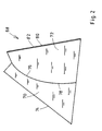
- Fig. 2 shows schematically a modified form of the prism with variable angular dispersion for the pre-monochromator.
- the prism 68 consists of two solid bodies 70 and 72 made of a transparent, dispersing material in the wavelength range used, e.g. Quartz.
- the body 70 has a flat front surface 74.
- the body 70 has a concave-cylindrical surface 76.
- the body 72 has a convex-cylindrical front surface 78 which is complementary to the surface 76.
- the surfaces 76 and 78 abut one another in such a way that rays pass through the separating surface essentially smoothly. If necessary, a liquid can be introduced between the surfaces 76 and 78, the refractive index and dispersion of which have essentially the same values as the material of the bodies 70 and 72.
- the body 72 has a flat rear surface 80.
- the surface 80 is provided with a mirror 82 Mistake.
- cylindrical surfaces e.g. spherical surfaces can also be provided.
Abstract
Description
- Die Erfindung betrifft einen Echelle-Polychromator, dem ein Vormonochromator mit einem Prisma vorgeschaltet ist, wobei der Vormonochromator und der Echelle-Polychromator durch einen gemeinsamen Spalt optisch miteinander verbunden sind.
- Ein Polychromator ist ein Spektralapparat, bei welchem durch ein dispergierendes Element ein Spektrum auf einem Detektorarray erzeugt wird, also einer Reihe von dicht nebeneinander angeordneten Detektorelementen. Auf diese Weise werden die spektralen Intensitäten bei den verschiedenen Wellenlängen eines von dem Detektorarray erfaßten Wellenlängenbereiches gleichzeitig gemessen. Bei einem Monochromator wird demgegenüber ein Spektrum in der Ebene eines Austrittsspaltes erzeugt. Durch diesen Austrittsspalt tritt dann das Licht aus einem bestimmten, relativ engen Wellenlängenbereich aus. Das durch den Austrittsspalt austretende Licht kann dann auf einen einzigen Detektor, z.B. einen Photomultiplier, fallen. Das durch den Austrittsspalt fallende Licht kann aber auch auf einen weiteren Monochromator oder Polychromator geleitet werden. In letzterem Falle spricht man von einem Vormonochromator. Vormonochromatoren dienen der Verminderung von Störlicht. Bei Gittermonochromatoren haben Vormonochromatoren die Aufgabe, Licht störender Ordnungen zu eliminieren.
- Ein Echelle-Gitter ist ein Gitter mit dreieckigem Furchenprofil, dessen Furchenabstände groß gegen die Wellenlänge sind. Ein Echelle-Gitter benutzt hohe Interferenz-Ordnungen. Ein Polychromator, der mit einem Echelle-Gitter arbeitet, ist ein Echelle-Polychromator.
- Verschiedene Typen von Monochromatoren und Polychromatoren sind beschrieben in einem Buch von J. Sternberg "The Design of Optical Spectrometers", Chapman and Hall, 1969, und in einem Buch von Y. Talmi "Multichannel Image Detectors", American Chemical Society, 1979.
- Die US-A-4 820 048 beschreibt einen Echelle-Polychromator in Kombination mit einem neuen Festkörper-Detektorarray. Dort wird zur simultanen Erfassung des gesamten Wellenlängenbereiches eine Trennung der Ordnungen innerhalb des Echelle-Polychromators vorgenommen. Dabei ergibt sich eine Begrenzung der Höhe des Eintrittsspaltes. Außerdem treten Abbildungsfehler in den Randbereichen des Spektrums auf. Der Streulichtpegel ist relativ hoch.
- Die GB-A-2 204 964 beschreibt einen Echelle-Polychromator für die Multielement-Analyse. Eine Lichtquelle erzeugt ein Lichtbündel, das durch zwei gekreuzte Eintrittsspalte begrenzt ist. Das Lichtbündel fällt auf einen Kollimatorspiegel. Der Kollimatorspiegel leitet das parallelgerichtete Lichtbündel durch ein Dispersionsprisma auf ein Echelle-Gitter. Die von dem Echelle-Gitter gebeugten Lichtbündel treten nochmals durch das Dispersionsprisma geleitet und werden von einem Kameraspiegel auf einem zweidimensionalen Detektorarray gesammelt. Das Dispersionsprisma bewirkt eine Dispersion in einer zur Dispersionsrichtung des Echelle-Gitters senkrechten Richtung und damit eine Trennung der verschiedenen Ordnungen des Echelle-Gitters. Das Detektorarray enthält Detektorelemente am Ort charakteristischer Spektrallinien der verschiedenen zu bestimmenden chemischen Elemente.
- Es ist ein Echelle-Monochromator bekannt, bei welchem die Ordnungen durch einen Vormonochromator getrennt werden. Der Vormonochromator erzeugt ein Spektrum in der Ebene eines Eintrittsspaltes des hochauflösenden Echelle-Monochromators.
- Von diesem Spektrum gelangt nur ein begrenzter Wellenlängenbereich in den Echelle-Monochromator. Der Echelle-Monochromator erfaßt dann aus diesem Wellenlängenbereich mit einem Austrittsspalt und einem dahinter angeordneten Detektor einen noch engeren Wellenlängenbereich. Solche Echelle-Doppelmonochromatoren erreichen ein hohes spektrales Auflösungsvermögen bei extrem niedrigem Streulichtanteil. Durch die größere Höhe der Spalte ergibt sich ein hoher Lichtleitwert. Es kann jedoch jeweils nur eine Spektralposition innerhalb des gesamten Spektrums untersucht werden (P.W.J.M. Boumans und J.J.A.M. Vrakking, "Spectrichimica Acta" Bd. 39B No. 9-11, 1239).
- Die DE-C-3 634 485 beschreibt ein Flüssigkeitsprisma mit veränderbarem Prismenwinkel zur Erzeugung spektral verzerrter Photographien und Projektionen.
- Durch die DE-A-33 26 868 ist ein Echelle-Polychromator mit vorgeschaltetem Prismenmonochromator bekannt. Der Prismenmonochromator ist mit dem Echelle-Polychromator durch einen gemeinsamen Spalt optisch verbunden.
- Der Erfindung liegt die Aufgabe zugrunde, einen Spektralapparat zu schaffen, der mit hoher Auflösung nicht nur eine bestimmte Spektralposition sondern zur gleichen Zeit auch deren Umgebung zu untersuchen gestattet, wobei Sorge getragen ist daß -abhängig von der jeweils beobachteten mittleren Wellenlänge- einerseits das Detektorarray vollständig ausgenutzt wird und andererseits störende Ordnungen, also Licht, das an dem Echelle-Gitter überlappende Spektren verschiedener Ordnung erzeugen würde, von dem Echelle-Polychromator ferngehalten werden.
- Erfindungsgemäß wird diese Aufgabe ausgehend von einem Echelle-Polychromator der eingangs genannten Art dadurch gelöst, daß die Lineardispersion des Vormonochromators dadurch veränderbar ist, daß der Prismenwinkel des Prismas einstellbar ist.
- Das Gerät nach der Erfindung benutzt ein Echelle-Gitter in Verbindung mit einem linearen Detektorarray, durch den gleichzeitig eine Vielzahl von Wellenlängen getrennt erfaßt wird. Es handelt sich insoweit um einen Polychromator. Das Gerät ist jedoch nicht dafür eingerichtet, einen großen Wellenlängenbereich zu erfassen, wie etwa der Echelle-Polychromator nach der vorerwähnten GB-A-2 204 964. Vielmehr wird mit hoher Auflösung durch das Echelle-Gitter eine bestimmte spektrale Position und deren nähere Umgebung untersucht. Zu diesem Zweck ist dem Echelle-Polychromator ein einfacher Prismen-Vormonochromator vorgeschaltet. Der Vormonochromator läßt nur einen begrenzten Spektralbereich zu dem Echelle-Polychromator durch. Durch die Einstellbarkeit des Prismenwinkels wird Sorge getragen, daß -abhängig von der jeweils beobachteten mittleren Wellenlänge- einerseits das Detektorarray vollständig ausgenutzt wird und andererseits störende Ordnungen, also Licht, das an dem Echelle-Gitter überlappende Spektren verschiedener Ordnung erzeugen würde, von dem Echelle-Polychromator ferngehalten werden.
- Die Erfindung schafft ein Gerät, das eigentlich ein Zwischending zwischen einem Monochromator und einem Polychromator ist: Das Gerät enthält einen Monochromator, nämlich den Vormonochromator, der einen engen Spektralbereich durch einen Eintrittsspalt des Echelle-Polychromators leitet. Das Gerät enthält aber auch einen Polychromator mit einem Detektorarray. Das Detektorarray beobachtet aber hier mit hoher Auflösung die Umgebung einer eingestellten mittleren Wellenlänge, nicht ein ausgedehntes, volles Spektrum.
- Ausgestaltungen der Erfindung sind Gegenstand der Unteransprüche.
- Ausführungsbeispiele der Erfindung sind nachstehend unter Bezugnahme auf die zugehörigen Zeichnungen näher erläutert.
-
- Fig.1
- ist eine Draufsicht auf einen Echelle-Polychromator mit Prismen-Vormonochromator.
- Fig.2
- zeigt eine andere Ausführung eines Prismas mit veränderbarer Winkeldispersion.
- In Fig.1 tritt ein Lichtbündel 10 von einer (nicht dargestellten) Lichtquelle durch einen Eintrittsspalt 12 eines Vormonochromators 14. Der Vormonochromator 14 ist ein Prismen-Monochromator in Littrow-Anordnung. Das Lichtbündel 10 fällt auf einen parabolischen Kollimatorspiegel 16. Der Kollimatorspiegel 16 erzeugt aus dem divergenten Lichtbündel 10 ein paralleles Lichtbündel 18. Das parallele Lichtbündel 18 fällt auf ein Prisma 20.
- Das Prisma 20 ist ein Flüssigkeits-Spiegelprisma mit veränderbarem Prismenwinkel. Das Prisma 20 enthält eine für das untersuchte Licht transparente, planparallele, vordere Platte 22 und eine hintere Platte 24. Die hintere Platte 24 ist an ihrer dem Kollimatorspiegel 16 zugewandten Vorderseite 26 verspiegelt. An der hinteren Platte 24 ist ein Spiegelhalter 28 befestigt. Der Spiegelhalter 28 hat zylindrische Grundform. An der plattenseitigen Stirnfläche 30 ist der Spiegelhalter 28 abgeschrägt. An dem entgegengesetzten Ende bildet der Spiegelhalter 28 einen Flansch 32. Ein Balg 34 erstreckt sich zwischen dem Flansch 32 und dem Rand der vorderen Platte 22. Zwischen der Platte 22, dem Balg 34 und dem Flansch 32 und um den Spiegelhalter 28 herum ist ein Hohlraum 36 gebildet. Dieser Hohlraum 36 ist mit einer lichtbrechenden Flüssigkeit gefüllt. Diese Flüssigkeit füllt auch den im Querschnitt dreieckigen Raum zwischen den beiden Platten 22 und 24.
- Die Platten 22 und 24 sind längs einer Kante 38 schwenkbar miteinander verbunden. Außerdem ist das gesamte Prisma 20 mit dem Spiegelhalter 28 und dem Balg 34 um eine Achse 40 schwenkbar gelagert. Die Achse 40 verläuft parallel zu der Kante 38 und zu der Richtung des Eintrittsspaltes 12. Die Achse 40 liegt in der Ebene der verspiegelten Vorderfläche 26 der Platte 24
- Die lichtbrechende Flüssigkeit ist destilliertes Wasser. Destilliertes Wasser hat im gesamten Wellenlängenbereich von 190 nm bis 850 nm hohe Transmission. Der Brechungsindex von destilliertem Wasser zeigt nur geringe Temperaturabhängigkeit.
- Die Platte 22 besteht aus geschmolzenem Quarz. Der Balg ist aus PTFE hergestellt.
- Das parallele Lichtbündel 18 wird durch das von der Platte 22 und der zwischen den Platten 22 und 24 befindlichen Flüssigkeit gebildete Prisma gebrochen und spektral zerlegt. Die so erhaltenen Lichtbündel werden von der verspiegelten Vorderfläche 26 der Platte 24 reflektiert. Die reflektierten Lichtbündel treten nochmals durch das Prisma 20 und erfahren eine erneute Dispersion. Die spektral zerlegten Lichtbündel laufen dann zu dem Kollimatorspiegel 16 zurück, wie durch Pfeil 42 angedeutet ist, und werden von dem Kollimatorspiegel 16 über einen Umlenkspiegel 44 in der Ebene eines Spaltes 46 gesammelt. In der Ebene des Spaltes 46 wird ein Spektrum als Bild des Eintrittsspaltes 12 erzeugt. In Fig.1 ist nur der Mittelstrahl des Lichtbündels 48 dargestellt, das auf der Mitte des Spaltes 46 fokussiert wird.
- Das Strahlenbündel 10 tritt mit einem Öffnungsverhältnis von F/8 durch den Eintrittsspalt 12 des Vormonochromators 14. Das Strahlenbündel wird an dem parabolischen Kollimatorspiegel 16 unter einem außeraxialen Winkel von etwa 8° reflektiert. Der Kollimatorspiegel 16 hat eine Brennweite von 400 mm.
- Der Spalt 46 läßt aus dem in der Ebene des Spaltes 46 erzeugten Spektrum einen engen Spektralbereich durch. Der Spalt 46 bildet den Eintrittsspalt eines Echelle-Polychromators 50. Der Echelle-Polychromator 50 enthält einen Kollimatorspiegel 52 und ein Echelle-Gitter 54. Von dem Spalt 46 geht ein divergentes Lichtbündel 56 mit dem engen Spektralbereich aus. Das Lichtbündel 56 wird durch einen Umlenkspiegel 58 umgelenkt. und fällt auf den Kollimatorspiegel 52. Der Kollimatorspiegel 52 erzeugt aus dem divergenten Lichtbündel 56 ein paralleles Lichtbündel 60. Das parallele Lichtbündel 60 fällt auf das Echelle-Gitter 54. Das Echelle-Gitter ist um eine Achse 62 verschwenkbar. Die Achse 62 ist parallel zu den Gitterfurchen. Die Gitterfurchen verlaufen senkrecht zur Papierebene in Fig.1.
- Das Echelle-Gitter 54 bewirkt eine Zerlegung des durch den Eintrittsspalt 46 eingetretenen Lichts. Von dem Echelle-Gitter gehen in verschiedene Richtungen parallele Lichtbündel mit den verschiedenen Wellenlängen des von dem Spalt ausgeblendeten Spektralbereiches aus. Die gebeugten Lichtbündel werden im wesentlichen in die Einfallsrichtung auf den Kollimatorspiegel 52 zurückgeworfen. Das ist durch einen Pfeil 64 in Fig.1 angedeutet. Die Lichtbündel mit den verschiedenen Wellenlängen werden durch den Kollimatorspiegel 52 in der Ebene eines Detektorarrays 66 fokussiert. Auf dem Detektorarray 66 wird ein Spektrum erzeugt. Das Spektrum erstreckt sich über das Detektorarray 66 von links nach rechts in Fig.1. Das der Mittenwellenlänge entsprechende Lichtbündel ist in Fig.1 mit 68 bezeichnet. Eine Blende 70 schirmt das Detektorarray gegen Störstrahlung ab. Zwischen dem Vormonochromator 14 und dem Echelle-Polychromator 50 ist eine Trennwand 72 vorgesehen. Der Eintrittsspalt 46 sitzt in dieser Trennwand 72.
- Das Echelle-Gitter 54 hat eine Strichzahl von 75 Furchen pro Millimeter und einen Blaze-Winkel von etwa 76°. Das Echelle-Gitter 54 wird im Interesse einer hohen Beugungseffektivität jeweils nahe der Autokollimation betrieben. Der Kollimatorspiegel 52 ist ein Parabolspiegel mit einer Brennweite von 400 mm. Das Detektorarray ist eine CCD-Zeile mit 512 Detektorelementen von je 0,023 mm Breite und 0,480 mm Höhe. Die Spaltbreite des Eintrittsspaltes 12 des Vormonochromators 14 ist doppelt so groß wie die Spaltbreite des Eintrittsspaltes 46 des Echelle-Polychromators 50. Damit wird der Eintrittsspalt des Echelle-Polychromators 56 für alle Wellenlängen, die mit dem Detektorarray gemessen werden sollen, vollständig ausgeleuchtet.
- Durch Einstellung der Platte 22 um die Achse 38 und der verspiegelten Platte 24 (zusammen mit dem gesamten Prisma 20) um die Achse 40 wird ein enger Wellenlängenbereich festgelegt, der durch den Spalt 46 hindurchtritt. Die Mittenwellenlänge des Bereiches wird durch das Lichtbündel 48 bestimmt, das nach der Brechung durch das Prisma 20 senkrecht von der verspiegelten Oberfläche 26 der Platte 24 reflektiert wird. Die spektrale Breite des durch den Spalt durchgelassenen Wellenlängenbereiches ist umso kleiner, je größer die Lineardispersion des Vormonochromators ist, hier also je größer die Winkeldispersion des Prismas 20 ist. Diese Winkeldispersion kann erhöht werden, indem die Platte 22 gegenüber der Platte 24 verschwenkt wird. Das dabei zwischen den Platten 22 und 24 verdrängte oder zwischen die Platten 22 und 24 angesaugte Flüssigkeitsvolumen wird von dem elastischen Balg 34 ausgeglichen.
- Der gewählte Spektralbereich am Eingangsspalt 46 des Echelle-Polychromators 50 mit der gewählten Mittenwellenlänge und der gewählten spektralen Breite wird nun durch den Echelle-Polychromator mit hoher Dispersion aufgespalten, und es wird ein entsprechendes Spektrum auf dem Detektorarray 66 erzeugt. Dazu wird das Echelle-Gitter 54 so verschwenkt, daß die Mittenwellenlänge etwa in der Mitte des Detektorarrays 66 liegt. Die Winkeldispersion des Prismas 20 und damit die spektrale Breite des Spektralbereiches wird so gewählt, daß die Länge des Detektorarrays 66 optimal ausgenutzt wird. Zu diesem Zweck wird die Winkeldispersion des Prismas 20 so gewählt, daß die folgende Bedingung erfüllt ist:

wobei dδ/dλ die Winkeldispersion des Prismas, λ die Wellenlänge, s die Breite des Eintrittsspaltes des Echelle-Polychromators, g die Gitterkonstante des Echelle-Gitters des Echelle-Polychromators, α,β Einfalls- bzw. Beugungswinkel am Echelle-Gitter, f₁ die Kamerabrennweite des Vormonochromators, f₂ die Kamerabrennweite des Echelle-Polychromators und l die Länge des Detektorarrays des Echelle-Polychromators ist. - Auf diese Weise ist sichergestellt, daß die Länge des Detektorarrays 66 voll ausgenutzt ist, also das zur vollständigen Ausleuchtung des Detektorarrays erforderliche Wellenlängenbereich durch den Eintrittsspalt 46 in den Echelle-Polychromator gelangt, und andererseits dieser Spektralbereich kleiner ist als der freie Wellenlängenbereich der benutzten Ordnung des Echelle-Gitters 54, so daß also keine Überlappung von Ordnungen stattfindet.
- Der Echelle-Polychromator mit Vormonochromator kann in verschiedener Weise abgewandelt werden.
- Fig.2 schematisch zeigt eine abgewandelte Form des Prismas mit veränderlicher Winkeldispersion für den Vormonochromator.
- Das Prisma 68 besteht aus zwei massiven Körpern 70 und 72 aus einem in dem benutzten Wellenlängenbereich transparenten, dispergierenden Material, z.B. Quarz. Der Körper 70 hat eine plane Vorderfläche 74. Auf der Rückseite weist der Körper 70 eine konkav-zylindrische Fläche 76 auf. Der Körper 72 weist eine zu der Fläche 76 komplementäre, konvex-zylindrische vordere Fläche 78 auf. Die Flächen 76 und 78 liegen so aneinander an, daß Strahlen im wesentlichen glatt durch die Trennfläche hindurchgehen. Erforderlichenfalls kann zwischen die Flächen 76 und 78 eine Flüssigkeit eingebracht werden, deren Brechungsindex und Dispersion im wesentlichen die gleichen Werte haben wie das Material der Körper 70 und 72. Der Körper 72 hat eine plane rückwärtige Fläche 80. Die Fläche 80 ist mit einer Verspiegelung 82 versehen. Durch Verschwenken der beiden Körper 70 und 72 gegeneinander kann der Prismenwinkel zwischen den Flächen 74 und 80 stetig verändert werden.
- Statt zylindrischer Flächen können z.B. auch sphärische Flächen vorgesehen sein.
Claims (9)
- Echelle-Polychromator (50), dem ein Vormonochromator (14) mit einem Prisma (20) vorgeschaltet ist, wobei der Vormonochromator (14) und der Echelle-Polychromator (50) durch einen gemeinsamen Spalt (46) optisch miteinander verbunden sind, dadurch gekennzeichnet, daß die Lineardispersion des Vormonochromators (14) dadurch veränderbar ist, daß der Prismenwinkel des Prismas (20) einstellbar ist.
- Echelle-Polychromator nach Anspruch 1, dadurch gekennzeichnet, daß das Prisma (20) eine vordere Platte (22) und eine rückwärtige Platte (24) aufweist, die einen veränderbaren Winkel bilden und zwischen sich einen mit Flüssigkeit gefüllen Hohlraum einschließen.
- Echelle-Polychromator nach Anspruch 1 oder 2, dadurch gekennzeichnet, daß der Vormonochromator (14) ein Prismen-Monochromator in Littrow-Anordnung mit einem Littrow-Spiegel (24,26) ist.
- Echelle-Polychromator nach Anspruch 3, dadurch gekennzeichnet, daß die rückwärtige Platte (24) des Prismas (20) zur Bildung des Littrow-Spiegels reflektierend ausgebildet ist.
- Echelle-Polychromator nach Anspruch 4, dadurch gekennzeichnet, daß der Littrow-Spiegel (24,26) und die vordere Platte (22) so gemeinsam verstellbar sind, daß auf einen Eintrittsspalt (46) des Echelle-Polychromators (50) ein Spektralbereich mit einer wählbaren Mittenwellenlänge geleitet wird, wobei die Winkeldispersion des Prismas (20) in Abhängigkeit von der gewählten Wellenlänge so gewählt ist, daß einerseits ein Detektorarray (66) des Echelle-Polychromators (50) optimal ausgeleuchtet und andererseits eine Überlappung von Ordnungen des von den Echelle-Polychromator (50) erzeugten Spektrums ausgeschlossen ist.
- Echelle-Polychromator nach Anspruch 5, dadurch gekennzeichnet, daß die Winkeldipsersion des Prismas (20) für eine vorgegebene Wellenlänge der Bedingung

- Echelle-Polychromator nach Anspruch 1, dadurch gekennzeichnet, daß das Prisma (68) aus zwei massiven Teilen (70,72) besteht, von denen einer die plane Vorderfläche (74) und der andere die plane rückwärtige Fläche (80) des Prismas (68) bildet und die einander zugewandte konkav-zylindrische bzw. komplementär dazu konvex-zylindrische, aneinander anliegende, eine Relativverdrehung der beiden Teile (70,72) gestattende Flächen (76,78) aufweisen.
- Echelle-Polychromator nach Anspruch 1, dadurch gekennzeichnet, daß das Prisma aus zwei massiven Teilen besteht, von denen einer die plane Vorderfläche und der andere die plane rückwärtige Fläche des Prismas bildet und die einander zugewandte konkav-sphärische bzw. komplementär dazu konvex-sphärische, aneinander anliegende, eine Relativverdrehung der beiden Teile gestattende Flächen aufweisen.
- Echelle-Polychromator nach Anspruch 5, dadurch gekennzeichnet, daß ein Eintrittsspalt (12) des Vormonochromators (14) die doppelte Breite hat wie der Eintrittsspalt (46) des Echelle-Polychromators (50).
Applications Claiming Priority (3)
| Application Number | Priority Date | Filing Date | Title |
|---|---|---|---|
| DE4118760 | 1991-06-06 | ||
| DE4118760A DE4118760A1 (de) | 1991-06-06 | 1991-06-06 | Echelle-doppelmonochromator |
| PCT/EP1992/001270 WO1992021948A1 (de) | 1991-06-06 | 1992-06-05 | Echelle-polychromator |
Publications (2)
| Publication Number | Publication Date |
|---|---|
| EP0587683A1 EP0587683A1 (de) | 1994-03-23 |
| EP0587683B1 true EP0587683B1 (de) | 1995-02-22 |
Family
ID=6433423
Family Applications (1)
| Application Number | Title | Priority Date | Filing Date |
|---|---|---|---|
| EP92911706A Expired - Lifetime EP0587683B1 (de) | 1991-06-06 | 1992-06-05 | Echelle-polychromator |
Country Status (5)
| Country | Link |
|---|---|
| US (1) | US5448351A (de) |
| EP (1) | EP0587683B1 (de) |
| AU (1) | AU657968B2 (de) |
| DE (2) | DE4118760A1 (de) |
| WO (1) | WO1992021948A1 (de) |
Families Citing this family (12)
| Publication number | Priority date | Publication date | Assignee | Title |
|---|---|---|---|---|
| DE19545178B4 (de) * | 1995-12-04 | 2008-04-10 | Berthold Gmbh & Co. Kg | Spektrometervorrichtung |
| US5889588A (en) * | 1996-09-24 | 1999-03-30 | Photon Technology International | Random wavelength access monochromator incorporating coaxial off-axis parabolic OAP reflectors |
| DE10205142B4 (de) * | 2002-02-07 | 2004-01-15 | Gesellschaft zur Förderung angewandter Optik, Optoelektronik, Quantenelektronik und Spektroskopie e.V. | Anordnung und Verfahren zur Wellenlängenkalibration bei einem Echelle-Spektrometer |
| SE0200627L (sv) * | 2002-03-01 | 2003-09-02 | Multichannel Instr Ab | Ljusdiffraktion |
| DE10347862B4 (de) * | 2003-10-10 | 2006-07-13 | Gesellschaft zur Förderung angewandter Optik, Optoelektronik, Quantenelektronik und Spektroskopie e.V. | Hochauflösendes Spektrometer |
| DE102009059280A1 (de) | 2009-12-22 | 2011-06-30 | Leibniz-Institut für Analytische Wissenschaften-ISAS-e.V., 44139 | Spektrometeranordnung |
| FR2970075B1 (fr) * | 2011-01-03 | 2013-02-01 | Centre Nat Etd Spatiales | Spectrometre imageur a grand champ |
| DE102012101019B4 (de) | 2012-02-08 | 2015-03-12 | Leibniz-Institut für Analytische Wissenschaften-ISAS-e.V. | Spektrometer-Anordnung für UV-VIS |
| US8867920B2 (en) | 2012-07-24 | 2014-10-21 | International Business Machines Corporation | Optical de-multiplexing device |
| CN102879091B (zh) * | 2012-08-28 | 2014-08-20 | 中国科学院长春光学精密机械与物理研究所 | 中阶梯光栅光谱仪、原子发射光谱仪及光谱测试方法 |
| US9134479B2 (en) | 2012-09-05 | 2015-09-15 | International Business Machines Corporation | Polarization diverse demultiplexing |
| US10088468B2 (en) * | 2016-02-04 | 2018-10-02 | Nova Biomedical Corporation | Analyte system and method for determining hemoglobin parameters in whole blood |
Family Cites Families (18)
| Publication number | Priority date | Publication date | Assignee | Title |
|---|---|---|---|---|
| AT150431B (de) * | 1935-07-19 | 1937-08-25 | Karl Dr Szigeti | Flüssigkeitsprisma mit veränderlichem Brechungswinkel. |
| US2605672A (en) * | 1945-03-21 | 1952-08-05 | American Cyanamid Co | Wernicke prism spectrometer |
| US3514192A (en) * | 1967-04-11 | 1970-05-26 | Dynasciences Corp | Achromatic variable-angle fluid prism |
| JPS4842749A (de) * | 1971-09-28 | 1973-06-21 | ||
| US4049353A (en) * | 1976-08-11 | 1977-09-20 | Spectrametrics, Incorporated | Spectrometric system and cassette |
| DE3224559A1 (de) * | 1982-07-01 | 1984-01-05 | Bodenseewerk Perkin-Elmer & Co GmbH, 7770 Überlingen | Monochromator |
| FR2530831B1 (fr) * | 1982-07-23 | 1986-02-28 | Trt Telecom Radio Electr | Dispositif de deviateur optique variable, application a une optique d'autodirecteur |
| DD210753A1 (de) * | 1982-10-01 | 1984-06-20 | Zeiss Jena Veb Carl | Anordnung zur auswahl von spektrenabschnitten aus einem gesamtspektrum |
| GB8322478D0 (en) * | 1983-08-20 | 1983-09-21 | Lasers Ltd J K | Dispersive prism arrangement |
| DE3403372C1 (de) * | 1984-02-01 | 1985-07-25 | Fraunhofer-Gesellschaft zur Förderung der angewandten Forschung e.V., 8000 München | Mehrkanal-Prozeß-Spektrometer |
| JPS60176017A (ja) * | 1984-02-23 | 1985-09-10 | Canon Inc | 光学素子 |
| FR2571153A1 (fr) * | 1984-10-01 | 1986-04-04 | Charriere Jean Pierre | Dispositif d'animation lumineuse |
| JPS6275401A (ja) * | 1985-09-27 | 1987-04-07 | Canon Inc | 光学素子 |
| DE3634485A1 (de) * | 1986-10-09 | 1988-04-14 | Berthold F Brichzig | Prisma fuer spektrale, verzerrte fotografien und projektionen |
| DD260326B5 (de) * | 1987-05-04 | 1993-11-25 | Zeiss Carl Jena Gmbh | Justierbare echelle-spektrometer-anordnung und verfahren zu dessen justage |
| US4820048A (en) * | 1987-11-19 | 1989-04-11 | The Perkin-Elmer Corporation | Detector for a spectrometer |
| JP3102485B2 (ja) * | 1989-10-04 | 2000-10-23 | 株式会社日立製作所 | 分光光度計 |
| US4995721A (en) * | 1990-03-05 | 1991-02-26 | Imo Industries, Inc. | Two-dimensional spectrometer |
-
1991
- 1991-06-06 DE DE4118760A patent/DE4118760A1/de not_active Withdrawn
-
1992
- 1992-06-05 DE DE59201468T patent/DE59201468D1/de not_active Expired - Lifetime
- 1992-06-05 WO PCT/EP1992/001270 patent/WO1992021948A1/de active IP Right Grant
- 1992-06-05 AU AU18965/92A patent/AU657968B2/en not_active Ceased
- 1992-06-05 US US08/157,034 patent/US5448351A/en not_active Expired - Fee Related
- 1992-06-05 EP EP92911706A patent/EP0587683B1/de not_active Expired - Lifetime
Also Published As
| Publication number | Publication date |
|---|---|
| EP0587683A1 (de) | 1994-03-23 |
| AU657968B2 (en) | 1995-03-30 |
| AU1896592A (en) | 1993-01-08 |
| DE4118760A1 (de) | 1992-12-10 |
| DE59201468D1 (de) | 1995-03-30 |
| US5448351A (en) | 1995-09-05 |
| WO1992021948A1 (de) | 1992-12-10 |
Similar Documents
| Publication | Publication Date | Title |
|---|---|---|
| EP1754032B1 (de) | Echelle-spektrometer mit verbesserter detektorausnutzung durch die verwendung zweier spektrometeranordnungen | |
| EP0321529B1 (de) | Vorrichtung zur messung von abständen zwischen einem optischen element mit grosser chromatischer aberration und einem gegenstand | |
| DE2364069C3 (de) | Spektralphotometer | |
| EP2516975B1 (de) | Spektrometeranordnung | |
| EP0098429B1 (de) | Monochromator | |
| DE60133002T2 (de) | Spektrophotometer mit mehreren weglängen | |
| US20040227939A1 (en) | Refractive-diffractive spectrometer | |
| EP0587683B1 (de) | Echelle-polychromator | |
| DE19853754B4 (de) | Simultanes Doppelgitter-Spektrometer mit Halbleiterzeilensensoren oder Photoelektronenvervielfachern | |
| EP0502866B1 (de) | Zweistrahl-spektrometer | |
| EP0442596B1 (de) | Echelle-Polychromator | |
| DE3614639C2 (de) | ||
| DE102017130772A1 (de) | Spektrometeranordnung, Verfahren zur Erzeugung eines zweidimensionalen Spektrums mittels einer solchen | |
| DE19961908C2 (de) | Hochauflösendes Littrow-Spektrometer und Verfahren zur quasi-simultanen Bestimmung einer Wellenlänge und eines Linienprofils | |
| EP2158460B1 (de) | Spektrometeranordnung | |
| DE1964509A1 (de) | Spektrophotometer | |
| DE2758141C2 (de) | Spektrophotometer | |
| DE102008050867B4 (de) | Verfahren zum Messen eines Spektrums einer schmalbandigen Lichtquelle sowie Spektrometeranordnung | |
| DE102011082469B4 (de) | Spektrometer mit wenigstens einem Zerstreuungselement | |
| DE10011462C2 (de) | Optisches Spektrometer mit Astigmatismuskompensation | |
| DE19543729B4 (de) | Spektrometer | |
| DE10207742B4 (de) | Atomabsorptionsspektroskopieverfahren und Atomabsorptionsspektrometer | |
| DE102014108138B4 (de) | Spektralsensor zur spektralen Analyse einfallenden Lichts | |
| DE2063533A1 (de) | Verfahren und Anordnung fur spektro skopische Messungen | |
| DE1547203A1 (de) | Vorrichtung zur Spektrographie mindestens eines Teiles eines primaeren Strahlungsspektrums |
Legal Events
| Date | Code | Title | Description |
|---|---|---|---|
| PUAI | Public reference made under article 153(3) epc to a published international application that has entered the european phase |
Free format text: ORIGINAL CODE: 0009012 |
|
| 17P | Request for examination filed |
Effective date: 19931206 |
|
| AK | Designated contracting states |
Kind code of ref document: A1 Designated state(s): DE FR GB |
|
| 17Q | First examination report despatched |
Effective date: 19940406 |
|
| GRAA | (expected) grant |
Free format text: ORIGINAL CODE: 0009210 |
|
| AK | Designated contracting states |
Kind code of ref document: B1 Designated state(s): DE FR GB |
|
| REF | Corresponds to: |
Ref document number: 59201468 Country of ref document: DE Date of ref document: 19950330 |
|
| GBT | Gb: translation of ep patent filed (gb section 77(6)(a)/1977) |
Effective date: 19950307 |
|
| ET | Fr: translation filed | ||
| PLBE | No opposition filed within time limit |
Free format text: ORIGINAL CODE: 0009261 |
|
| STAA | Information on the status of an ep patent application or granted ep patent |
Free format text: STATUS: NO OPPOSITION FILED WITHIN TIME LIMIT |
|
| 26N | No opposition filed | ||
| REG | Reference to a national code |
Ref country code: GB Ref legal event code: IF02 |
|
| PGFP | Annual fee paid to national office [announced via postgrant information from national office to epo] |
Ref country code: FR Payment date: 20110629 Year of fee payment: 20 |
|
| PGFP | Annual fee paid to national office [announced via postgrant information from national office to epo] |
Ref country code: GB Payment date: 20110628 Year of fee payment: 20 |
|
| PGFP | Annual fee paid to national office [announced via postgrant information from national office to epo] |
Ref country code: DE Payment date: 20110629 Year of fee payment: 20 |
|
| REG | Reference to a national code |
Ref country code: DE Ref legal event code: R071 Ref document number: 59201468 Country of ref document: DE |
|
| REG | Reference to a national code |
Ref country code: DE Ref legal event code: R071 Ref document number: 59201468 Country of ref document: DE |
|
| REG | Reference to a national code |
Ref country code: GB Ref legal event code: PE20 Expiry date: 20120604 |
|
| PG25 | Lapsed in a contracting state [announced via postgrant information from national office to epo] |
Ref country code: DE Free format text: LAPSE BECAUSE OF EXPIRATION OF PROTECTION Effective date: 20120606 |
|
| PG25 | Lapsed in a contracting state [announced via postgrant information from national office to epo] |
Ref country code: GB Free format text: LAPSE BECAUSE OF EXPIRATION OF PROTECTION Effective date: 20120604 |