EP2516902B1 - Sanitary outlet unit - Google Patents
Sanitary outlet unit Download PDFInfo
- Publication number
- EP2516902B1 EP2516902B1 EP10787011.5A EP10787011A EP2516902B1 EP 2516902 B1 EP2516902 B1 EP 2516902B1 EP 10787011 A EP10787011 A EP 10787011A EP 2516902 B1 EP2516902 B1 EP 2516902B1
- Authority
- EP
- European Patent Office
- Prior art keywords
- outlet
- water
- valve
- outlet unit
- unit according
- Prior art date
- Legal status (The legal status is an assumption and is not a legal conclusion. Google has not performed a legal analysis and makes no representation as to the accuracy of the status listed.)
- Active
Links
- XLYOFNOQVPJJNP-UHFFFAOYSA-N water Substances O XLYOFNOQVPJJNP-UHFFFAOYSA-N 0.000 claims description 91
- 238000005273 aeration Methods 0.000 claims description 15
- 239000003570 air Substances 0.000 claims description 13
- 239000012080 ambient air Substances 0.000 claims description 13
- 238000011144 upstream manufacturing Methods 0.000 claims description 9
- 238000007789 sealing Methods 0.000 claims description 8
- 239000000463 material Substances 0.000 claims description 3
- 238000003780 insertion Methods 0.000 claims description 2
- 230000037431 insertion Effects 0.000 claims description 2
- 229910010293 ceramic material Inorganic materials 0.000 claims 1
- 238000009423 ventilation Methods 0.000 description 53
- 239000000203 mixture Substances 0.000 description 3
- 238000005276 aerator Methods 0.000 description 2
- 230000004941 influx Effects 0.000 description 2
- 230000001105 regulatory effect Effects 0.000 description 2
- 230000001133 acceleration Effects 0.000 description 1
- 230000015572 biosynthetic process Effects 0.000 description 1
- 238000005422 blasting Methods 0.000 description 1
- 239000000919 ceramic Substances 0.000 description 1
- 239000012530 fluid Substances 0.000 description 1
- 230000002706 hydrostatic effect Effects 0.000 description 1
- 238000004519 manufacturing process Methods 0.000 description 1
- 239000012528 membrane Substances 0.000 description 1
- 238000000465 moulding Methods 0.000 description 1
- 230000003287 optical effect Effects 0.000 description 1
- 239000008234 soft water Substances 0.000 description 1
- 239000007787 solid Substances 0.000 description 1
- 239000007921 spray Substances 0.000 description 1
Images

Classifications
-
- F—MECHANICAL ENGINEERING; LIGHTING; HEATING; WEAPONS; BLASTING
- F16—ENGINEERING ELEMENTS AND UNITS; GENERAL MEASURES FOR PRODUCING AND MAINTAINING EFFECTIVE FUNCTIONING OF MACHINES OR INSTALLATIONS; THERMAL INSULATION IN GENERAL
- F16K—VALVES; TAPS; COCKS; ACTUATING-FLOATS; DEVICES FOR VENTING OR AERATING
- F16K24/00—Devices, e.g. valves, for venting or aerating enclosures
- F16K24/02—Devices, e.g. valves, for venting or aerating enclosures the enclosure being itself a valve, tap, or cock
-
- F—MECHANICAL ENGINEERING; LIGHTING; HEATING; WEAPONS; BLASTING
- F16—ENGINEERING ELEMENTS AND UNITS; GENERAL MEASURES FOR PRODUCING AND MAINTAINING EFFECTIVE FUNCTIONING OF MACHINES OR INSTALLATIONS; THERMAL INSULATION IN GENERAL
- F16K—VALVES; TAPS; COCKS; ACTUATING-FLOATS; DEVICES FOR VENTING OR AERATING
- F16K11/00—Multiple-way valves, e.g. mixing valves; Pipe fittings incorporating such valves
- F16K11/02—Multiple-way valves, e.g. mixing valves; Pipe fittings incorporating such valves with all movable sealing faces moving as one unit
- F16K11/06—Multiple-way valves, e.g. mixing valves; Pipe fittings incorporating such valves with all movable sealing faces moving as one unit comprising only sliding valves, i.e. sliding closure elements
- F16K11/078—Multiple-way valves, e.g. mixing valves; Pipe fittings incorporating such valves with all movable sealing faces moving as one unit comprising only sliding valves, i.e. sliding closure elements with pivoted and linearly movable closure members
- F16K11/0782—Single-lever operated mixing valves with closure members having flat sealing faces
- F16K11/0787—Single-lever operated mixing valves with closure members having flat sealing faces with both the supply and the discharge passages being on the same side of the closure members
Definitions
- the invention relates to a sanitary outlet unit with at least one water outlet having outlet fitting and provided with at least one ventilation device of the water jet ventilation device, which is arranged in the flow direction spaced from the at least one water outlet, and at least one valve member which the inflow of at least one water pipe to regulated the water outlet.
- jet regulator in which in the region of the water outlet, a jet regulator is arranged, which is to aerate the water jet emerging from the water outlet and form a homogeneous, pearly-soft water jet.
- the previously known jet regulators have in their jet regulator housing to a, usually designed as a perforated plate jet disperse, which is followed by a homogenizer and optionally a flow rectifier.
- the jet regulator housing of the previously known jet regulators has ventilation openings in the area of the homogenizing device, which are known as. Ventilation device for aerating the by means of the jet breaker temporarily divided into individual streams of water serve (see. DE-A-30 00 799 ).
- the previously known jet regulators are used with their jet regulator housing in an outlet mouthpiece that can be releasably secured to the fitting outlet by means of a screw connection.
- a pull-out arm From the DE 1 220 345 A is known a pull-out arm.
- Such Ausziehschwenkarme usually have an air admixing device. With these extendable swivel arms can be screwed at the outlet end no conventional jet regulator, as it could lead to leakage through the backflow to automatic pulling the extendable arm and leaks.
- the jet regulator is therefore attached to such telescopic pivot arms on the mounting side arm portion, the required air intake then takes place there.
- extendable pivot arms are often mounted so that the pivot tube is above the faucet to compensate for a low altitude of the tap above the drain basin.
- a shower head is already known, which is connected via a flexible hose with a kitchen extractor.
- the previously known shower head has a valve member 20 designed as a two-way valve, on which the user can select and set either a ventilated water jet or an annular shower spray with the aid of an actuator 120. While the aerated jet is generated by a central outlet-side jet aerator 70 serving as a ventilation device, the shower jet guided in the valve part via another fluid path is formed by an outlet-side hole circle 40 with flow holes 42 surrounding the jet regulator 70.
- the two-way valve serving as the valve member 20 is arranged in the flow direction in front of the Strahlbelstructureer 70 on the one hand and the bolt circle 40 on the other hand, wherein Strahlbelcontenter 70 and bolt circle 40 form the one and the other water outlet of the known outlet unit.
- the jet aerator 70 and the surrounding bolt circle 40 specify the outer contour of the previously known discharge unit in the region of its water outlet and can be sensibly realized only as a shower head.
- the achievement of this object is that the ventilation device in the at least one valve member is received, that the ventilation device has a ventilation duct, which is received in the at least one valve member, that the ventilation duct between an inlet opening contacted with the ambient air and an inflow upstream of an outlet of the valve member outlet opening runs, that the ventilation device provided with at least one actuator is whose movement between at least one closed position and at least one open position changes the supply of ambient air to the water jet in the interior of the valve member, and that the actuator engages in its closed position, the inlet opening of the ventilation device and seals.
- the ventilation function of the ventilation device is already integrated in the valve part.
- the ventilation device has a ventilation channel which is accommodated in the at least one valve part such that the ventilation channel runs between an inlet opening contacted with the ambient air and an outlet opening opening on the inflow side before a drain of the valve part. Since the air supply to the water flowing through takes place in the valve part and thus at a fairly far upstream point, the design of the water spout is not limited.
- the ventilation device is provided with at least one actuator whose movement between at least one closing and at least one open position changes the supply of ambient air to the water jet inside the valve member, wherein the actuator engages in its closed position, the inlet opening of the ventilation device and seals.
- the sealing means which are present anyway in the valve part, can be used to seal the ventilation device against returning water.
- the ventilation device is essentially formed by a ventilation duct running between an inlet opening in contact with the ambient air and an outlet opening in front of the outlet of the valve part, the ventilation duct extends through a region of the valve part between its two openings, so that its inlet opening is at least in the open position is arranged so that the fitting body does not prevent the intake of ambient air.
- the valve member is formed as arranged in the outlet fitting cartridge which regulates the flow of water from one or more water pipes in the direction of the water outlet and in the closed position of the cartridge in any case with respect to the outlet opening of the relevant line or lines a sealing Function perceives.
- the cartridge can be both one of a mixer tap, as well as a simple outlet top, which has only one line as an inlet and in which a possible mixture of water flows takes place in a mixing chamber seen downstream of the cartridges used.
- valve member at least two mutually movable valve elements, in particular a stationary and a stationary relative to this movable valve element, and at least one of the valve elements between a closed and an open position is movable.
- valve elements may be formed in a preferred embodiment of the outlet part, for example, as disc-like, with circular or oval surfaces to each other coming moldings as sealing elements that already exist through the choice of your material, such as in a ceramic, a plastic or a mixed form of these materials can and the arrangement in question a sealing function available put.
- a sealing function available put can be achieved by the movement of the valve elements together with a matched geometry of the access openings from several water pipes a desired mixture quantity.
- the position of the valve elements to one another regulates the access of water from more than one water line to a common mixing space, which lines in particular transport water of different temperatures.
- outlet unit forms a portion of the movable valve member of the valve member associated with the ventilation device actuator which engages over the inlet opening of the ventilation device and seals in its closed position, so that the vent opening when opening the inlet from the water pipes automatically released by the actuator becomes.
- a safe and easy to use embodiment of the outlet unit represents a single-lever mixer, in which a handle of the outlet unit is connected via an actuator with the movable valve element and actuation of the handle causes a substantially transverse thereto extending movement of the valve element, so that the valve elements can perform a mutually parallel movement.
- a ventilated or non-aerated water jet from the outlet unit according to the invention, it is advantageous if at least one further, independent of the first actuator second actuator for changing the air supply is provided on the ventilation device.
- this function could be used, for example, for the identification of temperature ranges, wherein one temperature range can be characterized by a laminar, another by a ventilated jet.
- an embodiment may consist in providing an admixing device upstream of the valve part in the region of the outlet opening of the ventilation device.
- the admixing device as a jet splitter, nozzle or similar cross-sectional constriction form part of the valve member, the device in question can then already as a component a cartridge provided and generates in the case of a cross-sectional constriction by the acceleration of the water jet on its downstream side a negative pressure.
- another expedient embodiment forms the formation of the admixing device as a separate insertion part, which can be inserted interchangeably into a region of the valve part, in particular in the embodiment as a jet regulator, which permits a demand-oriented selection and design of the jet emerging from the outlet.
- An advantageous embodiment of the outlet unit can be provided such that the ventilation device is provided with a retaining means which prevents the return of the water through the open position of the ventilation device and obstruction of the outlet of the water.
- the retaining means can then be provided as a check valve.
- the outlet Due to the arrangement of the ventilation device and optionally an admixing device upstream of the water outlet, the outlet can be designed freely within wide limits in the outlet fitting. Nevertheless, a useful development of the outlet unit may be to provide a receptacle for the arrangement of a jet regulator, beam direction generator or the like beam former at the water outlet.
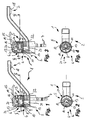
- a designated as a whole with 1 sanitary outlet unit with an outlet fitting 2 can be seen, which has a water outlet 3, due to the cuts II-II and IV-IV in the FIGS. 2 and 4 not shown.
- a valve member 5 an influx of water can be supplied, the delivery of which is regulated by the valve member 5 from the water outlet.
- a ventilation device 4 is arranged on the outlet unit 1, which is located in the flow direction spaced from a water outlet of the water outlet 3.
- the ventilation device 4 of the outlet unit 1 is, as in the FIGS. 1 and 3 can be seen, received in the valve member 5 and provided with an actuator 6, whose movement between an open and a closed position, the supply of ambient air to the water jet in the interior of the valve member 5 changes.
- the ventilation device 4 has a ventilation channel 10 which extends between an inlet opening which is in contact with the ambient air and an outlet opening 9 which opens out upstream of the outlet 20 of the valve part 5.
- the valve member 5 is formed in the embodiment as a cartridge of a single lever mixer tap and has a stationary and a movable valve element 11,12 which are mutually movable so that the movable valve element 12 from a closed position ( Fig.1 ) into an open position ( Figure 3 ) can be brought and vice versa.
- the handle 15 is actuated by a substantially upward pulling movement, whereby the with the Handle 16 associated actuator 16 has a slide plate 19 and connected thereto, the valve element 12 is moved or drives substantially perpendicular to the pulling movement.
- the actuator 6 is formed by the valve element 12 with its portion 14 and its connection to the slide plate 19.
- the ventilation channel 10 extends from an upwardly facing surface of the disc-like valve element 11 obliquely through this in the direction of a drain 20 of the valve member 5, in front of which inflow its outlet opening 9 opens at the bottom facing surface of the valve element 11.
- a mixing device 17 in the form of a change in cross section for accelerating the water jet and generating a negative pressure is arranged in the fixed valve element 11 upstream, such as Fig.1 to 6 is removable.
- a receptacle 18 is arranged at the free end of the water outlet.
- FIG.2 and the Figure 4 further shows that in the mentioned opening movement of the handle 15, the associated movement of the valve member 12 on the one hand, the flow of water from the two water pipes 7 in the mixing chamber 13 of the valve member 5 releases, on the other hand by this movement, the inlet port 8 for supplying ambient air to Ventilation of the water jet within the valve member 5 is released by movement of the portion 14 of the valve member 12.
- the fixed valve element 11 is a disk-shaped plate of substantially round cross section that of a substantially cylindrical receiving space 21 of the outlet fitting 2 is added.
- valve element 11 With a smaller diameter than the valve element 11 and the movable valve element 12 is formed with a substantially circular circumference, but in cross section has approximately the shape of a ring, wherein through the annular opening of the valve member 12 together with this closing upwards slide plate 19 of the mixing chamber 13 of the valve member 5 is formed.
- the solid valve element 11 facing the opening edge of the movable valve member 12 in this case has a relation to the handle 15 facing the opening edge narrowed cross-section, so that the first mentioned by the first opening edge in the closed position (see. Fig.1, 3 . 5 . 7 ) to overlapping openings are well covered by the edge.
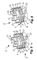
- FIGS. 1 to 4 was to be taken indirectly, in the representation of the FIGS. 5 and 6 which, in turn, the closing ( Figure 5 ) and the open position ( Figure 6 ) show the outlet unit, it is even clearer, has the form of a cartridge valve member 5 from below via two water pipes 7 supplied feeds 30 of water. These are two inlets 30 of water of different temperature in the two lines 7, which is mixed in the mixing chamber 13 to its outlet temperature.
- the supplied water is discharged in the selected cartridge shape by a downwardly facing drain 20 of the water jet in the direction of the water outlet, the water jet, the valve member 5 via a in the FIGS. 1 and 3 shown, downstream of the drain 20 arranged radial passage section leaves.
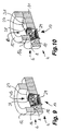
- FIGS. 7 and 8 has seen from the mixing chamber 13 in the direction downstream of the outlet 20, not shown, designed as a blasting admixing device 17 facing away from the viewer, non-visible side together with the outlet opening 9 of the ventilation device 4, also not shown, of which only the inlet opening. 8 in the Figure 8 can be seen in the flow 20 opens. Also the FIGS. 7 and 8 , but also the Fig.9 and 10th It can be seen that the viewer facing the opening edge of the movable valve member 12 quite forms an annular opening, while at the opposite, the fixed valve element facing the opening edge located cross-sectional constriction covers the water inlet openings.
- the cross-sectional narrowing of the respective opening edge is formed by two approximately semicircular convexly curved edge regions 27, which form the lying in the direction of movement, planar opening boundaries and which are connected by two arranged between them concave edge regions 28.
- the admixing device is formed in this embodiment as a jet regulator with a honeycomb-shaped, the mixing-promoting grating 29, and that passing through the admixing 17 water passing through the in open position ( Figure 10 ) released ventilation duct 10 of the ventilation device 4 in the valve part 5 of the sanitary outlet unit can be ventilated.
- the invention described above relates to a sanitary outlet unit 1 with an outlet fitting 2 having at least one water outlet and at least one ventilation device 4 provided for aeration of the water jet, which is arranged in the flow direction in front of the at least one water outlet 3, and with at least one valve part 5 which regulates the influx of at least one water pipe 7 to the water outlet 3.
- the ventilation device 4 is accommodated in the at least one valve member 5 and the ventilation device.
- valve member 5 is provided with at least one actuator 6, whose movement between at least one closing and at least one open position the supply of ambient air to the water jet in the interior of the valve member 5 changes.
Landscapes
- Engineering & Computer Science (AREA)
- General Engineering & Computer Science (AREA)
- Mechanical Engineering (AREA)
- Multiple-Way Valves (AREA)
- Domestic Plumbing Installations (AREA)
Description
Die Erfindung betrifft eine sanitäre Auslaufeinheit mit einer wenigstens einen Wasserauslauf aufweisenden Auslaufarmatur und mit zumindest einer zur Belüftung des Wasserstrahls vorgesehenen Belüftungseinrichtung, die in Strömungsrichtung beabstandet vor dem wenigstens einen Wasserauslauf angeordnet ist, und mit zumindest einem Ventilteil, welches den Zustrom aus wenigstens einer Wasserleitung zu dem Wasserauslauf reguliert.The invention relates to a sanitary outlet unit with at least one water outlet having outlet fitting and provided with at least one ventilation device of the water jet ventilation device, which is arranged in the flow direction spaced from the at least one water outlet, and at least one valve member which the inflow of at least one water pipe to regulated the water outlet.
Es sind bereits Auslaufeinheiten bekannt, bei welchen im Bereich des Wasserauslaufs ein Strahlregler angeordnet ist, der den aus dem Wasserauslauf austretenden Wasserstrahl belüften und zu einem homogenen, perlend-weichen Wasserstrahl formen soll. Die vorbekannten Strahlregler weisen in ihrem Strahlregler-Gehäuse dazu einen, meist als Lochplatte ausgestalteten Strahlzerleger auf, dem eine Homogenisiereinrichtung und gegebenenfalls ein Strömungsgleichrichter nachgeschaltet ist. Das Strahlreglergehäuse der vorbekannten Strahlregler weist im Bereich der Homogenisiereinrichtung Belüftungsöffnungen auf, die als. Belüftungseinrichtung zum Belüften des mittels des Strahlzerlegers vorübergehend in Einzelstrahlen aufgeteilten Wasserstrahls dienen (vgl.
Das zur Montage der vorbekannten Strahlregler benötigte Auslaufmundstück legt die Form sanitärer Auslaufarmaturen im Bereich des Armaturenauslaufs fest. Man ist jedoch zunehmend bestrebt, unkonventionelle und ästhetisch anspruchsvolle Auslaufarmaturen zu gestalten.The outlet nozzle required for mounting the previously known jet regulators determines the shape of sanitary outlet fittings in the area of the valve outlet. However, there is an increasing desire To design unconventional and aesthetically sophisticated outlet fittings.
Aus der
Außerdem kennt man aus der
Aus der
Es besteht daher die Aufgabe, eine sanitäre Auslaufeinheit zur Verfügung zu stellen, die eine zuverlässige Belüftung des Wasserstrahls bei hoher Dichtigkeit gegen rücklaufendes Wasser gewährleistet und sich ohne größere konstruktive Änderungen in bestehende Armaturen integrieren lässt.It is therefore an object to provide a sanitary outlet unit available that ensures reliable ventilation of the water jet with high tightness against returning water and can be integrated without major structural changes in existing fittings.
Die erfindungsgemäße Lösung dieser Aufgabe besteht darin, dass die Belüftungseinrichtung in dem zumindest einen Ventilteil aufgenommen ist, dass die Belüftungseinrichtung einen Belüftungskanal aufweist, der derart in dem zumindest einen Ventilteil aufgenommen ist, dass der Belüftungskanal zwischen einer mit der Umgebungsluft kontaktierten Einlassöffnung und einer zuströmseitig vor einem Ablauf des Ventilteils mündenden Auslassöffnung verläuft, dass die Belüftungseinrichtung mit wenigstens einem Stellglied versehen ist, dessen Bewegung zwischen wenigstens einer Schließstellung und mindestens einer Offenstellung die Zufuhr von Umgebungsluft zu dem Wasserstrahl im Inneren des Ventilteils ändert, und dass das Stellglied in seiner Schließstellung die Einlassöffnung der Belüftungseinrichtung übergreift und abdichtet.The achievement of this object is that the ventilation device in the at least one valve member is received, that the ventilation device has a ventilation duct, which is received in the at least one valve member, that the ventilation duct between an inlet opening contacted with the ambient air and an inflow upstream of an outlet of the valve member outlet opening runs, that the ventilation device provided with at least one actuator is whose movement between at least one closed position and at least one open position changes the supply of ambient air to the water jet in the interior of the valve member, and that the actuator engages in its closed position, the inlet opening of the ventilation device and seals.
Bei der erfindungsgemäßen Auslaufeinheit ist also die Belüftungsfunktion der Belüftungseinrichtung bereits in dem Ventilteil integriert. Die Belüftungseinrichtung weist dazu einen Belüftungskanal auf, der derart in dem zumindest einen Ventilteil aufgenommen ist, dass der Belüftungskanal zwischen einer mit der Umgebungsluft kontaktierten Einlassöffnung und einer zuströmseitig vor einem Ablauf des Ventilteils mündenden Auslassöffnung verläuft. Da die Luftzufuhr zum durchströmenden Wasser im Ventilteil und somit an einem recht weit stromaufwärts befindlichen Punkt stattfindet, unterliegt die Gestaltung des Wasserauslaufs keinen Einschränkungen. Die Belüftungseinrichtung ist mit wenigstens einem Stellglied versehen, dessen Bewegung zwischen wenigstens einer Schließ- und mindestens einer Offenstellung die Zufuhr von Umgebungsluft zu dem Wasserstrahl im Inneren des Ventilteils ändert, wobei das Stellglied in seiner Schließstellung die Einlassöffnung der Belüftungseinrichtung übergreift und abdichtet. Da mittels dem Stellglied die Zufuhr von Umgebungsluft zu dem Wasserstrahl im Inneren des Ventilteils geändert werden kann und da das Stellglied in seiner Schließstellung die Einlassöffnung der Belüftungseinrichtung im Inneren des Ventilteils übergreift und abdichtet, können die im Ventilteil ohnehin vorhandenen Dichtmittel zur Abdichtung der Belüftungseinrichtung gegen rücklaufendes Wasser mitgenutzt werden.In the outlet unit according to the invention, therefore, the ventilation function of the ventilation device is already integrated in the valve part. For this purpose, the ventilation device has a ventilation channel which is accommodated in the at least one valve part such that the ventilation channel runs between an inlet opening contacted with the ambient air and an outlet opening opening on the inflow side before a drain of the valve part. Since the air supply to the water flowing through takes place in the valve part and thus at a fairly far upstream point, the design of the water spout is not limited. The ventilation device is provided with at least one actuator whose movement between at least one closing and at least one open position changes the supply of ambient air to the water jet inside the valve member, wherein the actuator engages in its closed position, the inlet opening of the ventilation device and seals. Since the supply of ambient air to the water jet in the interior of the valve member can be changed by means of the actuator and since the actuator in its closed position, the inlet opening the ventilation device engages over and seals in the interior of the valve part, the sealing means, which are present anyway in the valve part, can be used to seal the ventilation device against returning water.
Da die Belüftungseinrichtung im wesentlichen durch einen, zwischen einer mit der Umgebungsluft kontaktierten Einlassöffnung und einer zuströmseitig vor dem Ablauf des Ventilteils mündenden Auslassöffnung verlaufenden Belüftungskanal gebildet ist, durchgreift der Belüftungskanal zwischen seinen beiden Öffnungen einen Bereich des Ventilteils, so dass seine Einlassöffnung zumindest in der Offenstellung so angeordnet ist, dass der Armaturenkörper das Ansaugen von Umgebungsluft nicht verhindert.Since the ventilation device is essentially formed by a ventilation duct running between an inlet opening in contact with the ambient air and an outlet opening in front of the outlet of the valve part, the ventilation duct extends through a region of the valve part between its two openings, so that its inlet opening is at least in the open position is arranged so that the fitting body does not prevent the intake of ambient air.
Bevorzugt ist bei einer Ausführung der erfindungsgemäßen Auslaufeinheit das Ventilteil als in der Auslaufarmatur angeordnete Kartusche ausgebildet, die den Zustrom von Wasser aus einer oder mehreren Wasserleitungen in Richtung des Wasserauslaufs reguliert und bei Schließstellung der Kartusche jedenfalls gegenüber der Auslauföffnung der betreffenden Leitung bzw. Leitungen eine dichtende Funktion wahrnimmt. Die Kartusche kann sowohl eine solche einer Mischbatterie, als auch eines einfachen Auslaufoberteils sein, die lediglich eine Leitung als Zulauf aufweist und bei welcher eine eventuelle Mischung von Wasserströmen in einem von den verwendeten Kartuschen gesehen stromabwärts befindlichen Mischraum stattfindet.Preferably, in one embodiment of the outlet unit according to the invention, the valve member is formed as arranged in the outlet fitting cartridge which regulates the flow of water from one or more water pipes in the direction of the water outlet and in the closed position of the cartridge in any case with respect to the outlet opening of the relevant line or lines a sealing Function perceives. The cartridge can be both one of a mixer tap, as well as a simple outlet top, which has only one line as an inlet and in which a possible mixture of water flows takes place in a mixing chamber seen downstream of the cartridges used.
Ein gut regulierbarer Zufluss aus einer oder mehreren Zuleitungen der Auslaufarmatur wird bei einer Weiterbildung der Auslaufeinheit erreicht, bei der das Ventilteil wenigstens zwei gegeneinander bewegliche Ventilelemente, insbesondere eine ortsfestes und ein gegenüber diesem ortsfesten bewegliches Ventilelement aufweist, und wenigstens eines der Ventilelemente zwischen einer Schließ- und einer Offenstellung bewegbar ist.A well adjustable inflow from one or more supply lines of the outlet fitting is achieved in a development of the outlet unit, wherein the valve member at least two mutually movable valve elements, in particular a stationary and a stationary relative to this movable valve element, and at least one of the valve elements between a closed and an open position is movable.
Die Ventilelemente können bei einer bevorzugten Ausführung des Auslaufteils beispielsweise als scheibenartige, mit kreisförmigen oder ovalen Flächen aufeinander zu liegen kommende Formteile als Dichtelemente ausgebildet sein, die bereits durch die Wahl Ihres Materials, das etwa in einer Keramik, einem Kunststoff oder einer Mischform dieser Materialien bestehen kann und der betreffenden Anordnung eine dichtende Funktion zur Verfügung stellen. Außerdem lässt sich durch die Bewegung der Ventilelemente gegeneinander zusammen mit einer angepassten Geometrie der Zutrittsöffnungen aus mehreren Wasserleitungen eine gewünschte Mengenmischung erreichen.The valve elements may be formed in a preferred embodiment of the outlet part, for example, as disc-like, with circular or oval surfaces to each other coming moldings as sealing elements that already exist through the choice of your material, such as in a ceramic, a plastic or a mixed form of these materials can and the arrangement in question a sealing function available put. In addition, can be achieved by the movement of the valve elements together with a matched geometry of the access openings from several water pipes a desired mixture quantity.
Bei einer bevorzugten Ausführung der Auslaufeinheit reguliert die Position der Ventilelemente zueinander den Zutritt von Wasser aus mehr als einer Wasserleitung zu einem gemeinsamen Mischraum, welche Leitungen insbesondere Wasser unterschiedlicher Temperatur transportieren. Durch die Bewegung der Ventilelemente gegeneinander zusammen mit einer angepassten Geometrie der Zutrittsöffnungen aus mehreren Wasserleitungen lässt sich hierbei eine gewünschte Mengenmischung erreichen.In a preferred embodiment of the outlet unit, the position of the valve elements to one another regulates the access of water from more than one water line to a common mixing space, which lines in particular transport water of different temperatures. By the movement of the valve elements against each other together with an adapted geometry of the access openings from several water pipes can be achieved here a desired amount mixture.
Besonders einfach herzustellen und wirkungsvoll zu steuern ist die Belüftung einer Ausführung der erfindungsgemäßen Auslaufeinheit, die die Einlassöffnung der Belüftungseinrichtung durch ein mit dem beweglichen Ventilelement zusammenwirkendes Dichtelement verschließ- und abdichtbar vorsieht, so dass etwa ein Überführen des Stellglieds aus einer Schließ- in die Offenstellung gleichzeitig das Dichtelement in eine Offenstellung bezüglich der Einlassöffnung bringt.Particularly easy to manufacture and effective control is the ventilation of an embodiment of the outlet unit according to the invention, the sealing opening and closing the inlet opening of the ventilation device by a cooperating with the movable valve element sealable and provides so that about a transfer of the actuator from a closed to the open position simultaneously brings the sealing element in an open position with respect to the inlet opening.
Bei einer besonders bevorzugten Ausführungsform der Auslaufeinheit bildet dann ein Abschnitt des beweglichen Ventilelements des Ventilteils das der Belüftungseinrichtung zugeordnete Stellglied, welches in seiner Schließstellung die Einlassöffnung der Belüftungseinrichtung übergreift und abdichtet, so dass die Belüftungsöffnung bei Öffnung des Zulaufs aus den Wasserleitungen durch das Stellglied automatisch freigegeben wird.In a particularly preferred embodiment of the outlet unit then forms a portion of the movable valve member of the valve member associated with the ventilation device actuator which engages over the inlet opening of the ventilation device and seals in its closed position, so that the vent opening when opening the inlet from the water pipes automatically released by the actuator becomes.
Eine sicher und einfach bedienbare Ausführungsform der Auslaufeinheit stellt eine Einhebel-Mischbatterie dar, bei der eine Handhabe der Auslaufeinheit über ein Stellorgan mit dem beweglichen Ventilelement verbunden ist und eine Betätigung der Handhabe eine im wesentlichen quer hierzu verlaufende Bewegung des Ventilelements auslöst, so dass die Ventilelemente eine zueinander parallele Bewegung ausführen können.A safe and easy to use embodiment of the outlet unit represents a single-lever mixer, in which a handle of the outlet unit is connected via an actuator with the movable valve element and actuation of the handle causes a substantially transverse thereto extending movement of the valve element, so that the valve elements can perform a mutually parallel movement.
Um wahlweise einen belüfteten oder unbelüfteten Wasserstrahl aus der erfindungsgemäßen Auslaufeinheit zu erhalten ist es von Vorteil, wenn an der Belüftungseinrichtung wenigstens ein weiteres, von dem ersten Stellglied unabhängiges zweites Stellglied zur Änderung der Luftzufuhr vorgesehen ist. Im Falle einer Mischbatterie für die Mischung von Wasser unterschiedlicher Temperatur könnte diese Funktion beispielsweise zur Kenntlichmachung von Temperaturbereichen eingesetzt werden, wobei ein Temperaturbereich durch einen laminaren, ein anderer durch einen belüfteten Strahl gekennzeichnet sein kann.In order to optionally obtain a ventilated or non-aerated water jet from the outlet unit according to the invention, it is advantageous if at least one further, independent of the first actuator second actuator for changing the air supply is provided on the ventilation device. In the case of a mixer for the mixing of water of different temperature, this function could be used, for example, for the identification of temperature ranges, wherein one temperature range can be characterized by a laminar, another by a ventilated jet.
Um bei der erfindungsgemäßen Auslaufeinheit eine besonders gute Durchmischung des Wasserstrahls mit Luft zu erreichen, kann eine Ausführung darin bestehen, an dem Ventilteil im Bereich der Auslassöffnung der Belüftungseinrichtung stromaufwärts eine Zumischeinrichtung vorzusehen.In order to achieve a particularly good mixing of the water jet with air in the outlet unit according to the invention, an embodiment may consist in providing an admixing device upstream of the valve part in the region of the outlet opening of the ventilation device.
Um mittels der Zumischeinrichtung den Strahl bereits zu zerlegen oder mittels des strömenden Wasserstrahls Luft anzusaugen und dann unter Durchmischung mitzureißen kann bei einer vorteilhafte Ausführungsform die Zumischeinrichtung als Strahlzerleger, Düse oder dergleichen Querschnittsverengung einen Bestandteil des Ventilteils bilden, die betreffende Einrichtung kann dann also bereits als Bestandteil einer Kartusche vorgesehen sein und erzeugt im Falle einer Querschnittsverengung durch die Beschleunigung des Wasserstrahl auf seiner Abströmseite einen Unterdruck.In order to disassemble the beam already by means of the admixing or sucking air by means of the flowing water jet and then entrainment with mixing, in an advantageous embodiment, the admixing device as a jet splitter, nozzle or similar cross-sectional constriction form part of the valve member, the device in question can then already as a component a cartridge provided and generates in the case of a cross-sectional constriction by the acceleration of the water jet on its downstream side a negative pressure.
Eine andere zweckmäßige Ausführungsform bildet in diesem Zusammenhang die Ausbildung der Zumischeinrichtung als in einen Bereich des Ventilteils austauschbar einbringbares, separates Einsetzteil, insbesondere in der Ausgestaltung als Strahlregler, der eine bedarfsorientierte Auswahl und Gestaltung des aus dem Auslauf austretenden Strahls gestattet.In this context, another expedient embodiment forms the formation of the admixing device as a separate insertion part, which can be inserted interchangeably into a region of the valve part, in particular in the embodiment as a jet regulator, which permits a demand-oriented selection and design of the jet emerging from the outlet.
Eine vorteilhafte Ausführungsform der Auslaufeinheit kann derart vorgesehen sein, dass die Belüftungseinrichtung mit einem Rückhaltemittel versehen ist, welches bei Offenstellung der Belüftungseinrichtung und Behinderung des Auslaufs des Wassers ein Zurückströmen des Wassers durch diese verhindert.An advantageous embodiment of the outlet unit can be provided such that the ventilation device is provided with a retaining means which prevents the return of the water through the open position of the ventilation device and obstruction of the outlet of the water.
Bei einer zweckmäßigen Weiterbildung kann dann das Rückhaltemittel als Rückschlagventil vorgesehen sein.In an expedient development, the retaining means can then be provided as a check valve.
Durch die Anordnung der Belüftungseinrichtung sowie wahlweise einer Zumischeinrichtung stromaufwärts von dem Wasserauslauf kann bei der Auslaufarmatur der Auslauf in weiten Grenzen frei gestaltet werden. Trotzdem kann eine sinnvolle Weiterbildung der Auslaufeinheit darin bestehen, an dem Wasserauslauf eine Aufnahme zur Anordnung eines Strahlreglers, Strahlrichtungsgeber oder dergleichen Strahlformer vorzusehen.Due to the arrangement of the ventilation device and optionally an admixing device upstream of the water outlet, the outlet can be designed freely within wide limits in the outlet fitting. Nevertheless, a useful development of the outlet unit may be to provide a receptacle for the arrangement of a jet regulator, beam direction generator or the like beam former at the water outlet.
Die Erfindung wird nachstehend anhand von Ausführungsbeispielen in der Zeichnung näher erläutert. Es zeigen hierbei in teilweise schematisierter Form die
- Fig.1
- eine geschnittene Seitenansicht eines ersten Ausführungsbeispiels einer Auslaufeinheit mit Auslaufarmatur mit Wasserauslauf und mit einer in einem Ventilteil aufgenommenen Belüftungseinrichtung sowie mit einem in Schließstellung befindlichen Stellglied
- Fig. 2
- eine Schnittansicht von oben der Auslaufeinheit aus der
Fig.1 entlang der Schnittlinie II-II - Fig. 3
- eine geschnittene Seitenansicht der Auslaufeinheit aus der
Fig.1 mit in Offenstellung befindlichem Stellglied; , - Fig. 4
- eine Schnittansicht von oben auf die Auslaufeinheit der
Fig.3 entlang der Schnittlinie IV-IV; - Fig. 5
- eine perspektivische, längs geschnittene Ansicht des Ventilteils der Auslaufeinheit von schräg unten in der Schließstellung der
Fig.1 und 3 ; - Fig. 6
- eine perspektivische, längs geschnittene Ansicht des Ventilteils der Auslaufeinheit von schräg unten in der Offenstellung der
Fig.2 und 4 ; - Fig. 7
- eine Draufsicht von oben auf ein zweites Ausführungsbeispiel von in Schließstellung befindlichen Ventilelementen eines Ventilteils mit einem Strahlregler als abströmseitig angeordnete Zumischeinrichtung;
- Fig. 8
- eine Draufsicht von oben auf die Ventilelemente des Ventilteils aus der
Fig.7 in Offenstellung; - Fig. 9
- eine perspektivische, längs geschnittene Seitenansicht des Ventilteils der
Fig.7 ; - Fig.10
- eine perspektivische, längs geschnittene Seitenansicht des Ventilteils der
Fig.8
- Fig.1
- a sectional side view of a first embodiment of an outlet unit with outlet fitting with water outlet and with a in a valve member accommodated ventilation device and with an actuator located in the closed position
- Fig. 2
- a sectional view from above of the outlet unit of the
Fig.1 along the section line II-II - Fig. 3
- a sectional side view of the outlet unit of the
Fig.1 with the actuator in the open position; . - Fig. 4
- a sectional view from above of the outlet unit of
Figure 3 along the section line IV-IV; - Fig. 5
- a perspective, longitudinal sectional view of the valve member of the outlet unit of obliquely from below in the closed position of
FIGS. 1 and 3 ; - Fig. 6
- a perspective, longitudinal sectional view of the valve member of the outlet unit of obliquely from below in the open position of
FIGS. 2 and 4 ; - Fig. 7
- a plan view from above of a second embodiment of valve elements located in the closed position of a valve member with a jet regulator as arranged downstream of the admixing device;
- Fig. 8
- a plan view from above of the valve elements of the valve member from the
Figure 7 in open position; - Fig. 9
- a perspective, longitudinal side view of the valve member of the
Figure 7 ; - Figure 10
- a perspective, longitudinal side view of the valve member of the
Figure 8
In den
Die Belüftungseinrichtung 4 der Auslaufeinheit 1 ist, wie in den
Eine Betrachtung der
Wie bereits den vorhergehenden
Das Ausführungsbeispiel der
Besser als den
Die vorstehend beschriebene Erfindung betrifft demnach eine sanitäre Auslaufeinheit 1 mit einer wenigstens einen Wasserauslauf 3 aufweisenden Auslaufarmatur 2 und mit zumindest einer zur Belüftung des Wasserstrahls vorgesehenen Belüftungseinrichtung 4, die in Strömungsrichtung beabstandet vor dem wenigstens einen Wasserauslauf 3 angeordnet ist, und mit zumindest einem Ventilteil 5, welches den Zustrom aus wenigstens einer Wasserleitung 7 zu dem Wasserauslauf 3 reguliert. Um eine sanitäre Auslaufeinheit 1 zur Verfügung zu haben, die eine zuverlässige Belüftung des Wasserstrahls bei hoher Dichtigkeit gegen rücklaufendes Wasser gewährleistet und sich ohne größere konstruktive Änderungen in bestehende Armaturen integrieren lässt, ist die Belüftungseinrichtung 4 in dem zumindest einen Ventilteil 5 aufgenommen und die Belüftungseinrichtung 4 ist mit wenigstens einem Stellglied 6 versehen, dessen Bewegung zwischen wenigstens einer Schließ- und wenigstens einer Offenstellung die Zufuhr von Umgebungsluft zu dem Wasserstrahl im Innern des Ventilteils 5 ändert. Bei größtmöglicher Gestaltungsfreiheit für Neugestaltungen der Armaturform kann durch die erfindungsgemäße Auslaufeinheit 1 aber auch auf bereits in hoher Zahl vorhandene Gestaltungen zurückgegriffen werden, ohne dass diese gestalterischen Änderungen unterliegen müssten.Accordingly, the invention described above relates to a
Claims (15)
- Sanitary outlet unit comprising an outlet fitting which has at least one water outlet and comprising at least one aeration device (4) which is provided for aerating the water jet and is arranged upstream of the at least one water outlet at a distance therefrom in the direction of flow, and comprising at least one valve part (5) which regulates the inflow from at least one water line to the water outlet, characterized in that the aeration device (4) is received in the at least one valve part (5), in that the aeration device (4) has an aeration channel (10), which is received in the at least one valve part (5) in such a manner that the aeration channel (10) runs between an intake opening (8) which is contacted by the ambient air and a discharge opening (9) which issues out upstream of a drain (20) of the valve part (5) on the inflow side, in that the aeration device (4) is provided with at least one actuator (6), the movement of which between at least one closed position and at least one open position changes the admission of ambient air to the water jet inside the valve part (5), and in that the actuator (6), in the closed position thereof, overlaps and seals off the intake opening (8) of the aeration device (4).
- Outlet unit according to Claim 1, characterized in that the valve part (5) is in the form of a cartridge arranged in the outlet fitting (2).
- Outlet unit according to Claim 1 or 2, characterized in that the valve part (5) has at least two valve elements (11, 12) which are movable with respect to one another, in particular a stationary valve element (11) and a valve element (12) which is movable in relation to said stationary valve element (11), and in that at least one of the valve elements (12) can move between a closed position and an open position.
- Outlet unit according to Claim 3, characterized in that the valve elements (11, 12) are provided as disk-like sealing elements, in particular formed from a ceramic material and/or a plastic material.
- Outlet unit according to Claim 3 or 4, characterized in that the position of the valve elements (11, 12) in relation to one another regulates the admission of water from more than one water line (7) to a common mixing space (13), which lines (7) in particular transport water at differing temperature.
- Outlet unit according to one of the preceding claims, characterized in that the intake opening (8) of the aeration device (4) can be closed and sealed off by a sealing element which interacts with the movable valve element (12).
- Outlet unit according to one of Claims 3 to 6, characterized in that a portion (14) of the movable valve element (12) of the valve part (5) forms the actuator (6) assigned to the aeration device (4).
- Outlet unit according to one of the preceding claims, characterized in that a lever (15) of the outlet unit (1) is connected to the movable valve element (12) via a final control element (16), and actuation of the lever (15) triggers a movement of the valve element (12) which runs substantially transversely in relation to the actuation direction.
- Outlet unit according to one of the preceding claims, characterized in that at least one further, second actuator, which is independent of the first actuator (6), is provided on the aeration device (4) for changing the admission of air.
- Outlet unit according to one of the preceding claims, characterized in that a mixing device (17) is provided on the valve part (5) upstream in the region of the discharge opening (9) of the aeration device (4).
- Outlet unit according to Claim 10, characterized in that the mixing device (17), as a jet splitter, nozzle or similar cross section constriction, forms a component part of the valve part (5).
- Outlet unit according to Claim 10, characterized in that the mixing device (17) is provided as a separate insertion part which can be introduced into a region of the valve part (5), in particular as a jet regulator.
- Outlet unit according to one of the preceding claims, characterized in that the aeration device (4) is provided with a retaining means which, when the aeration device (4) is in the open position, prevents the water from flowing back through the latter.
- Outlet unit according to Claim 12, characterized in that the retaining means is provided as a non-return valve.
- Outlet unit according to one of the preceding claims, characterized in that a receptacle (18) for the arrangement of a jet regulator, jet director or similar jet former is provided on the water outlet (3).
Applications Claiming Priority (2)
| Application Number | Priority Date | Filing Date | Title |
|---|---|---|---|
| DE102009060501A DE102009060501B3 (en) | 2009-12-23 | 2009-12-23 | Sanitary outlet unit |
| PCT/EP2010/007039 WO2011076320A1 (en) | 2009-12-23 | 2010-11-19 | Sanitary outlet unit |
Publications (2)
| Publication Number | Publication Date |
|---|---|
| EP2516902A1 EP2516902A1 (en) | 2012-10-31 |
| EP2516902B1 true EP2516902B1 (en) | 2013-05-01 |
Family
ID=43608815
Family Applications (1)
| Application Number | Title | Priority Date | Filing Date |
|---|---|---|---|
| EP10787011.5A Active EP2516902B1 (en) | 2009-12-23 | 2010-11-19 | Sanitary outlet unit |
Country Status (7)
| Country | Link |
|---|---|
| US (1) | US9297468B2 (en) |
| EP (1) | EP2516902B1 (en) |
| CN (2) | CN201915451U (en) |
| DE (1) | DE102009060501B3 (en) |
| ES (1) | ES2423654T3 (en) |
| PT (1) | PT2516902E (en) |
| WO (1) | WO2011076320A1 (en) |
Families Citing this family (4)
| Publication number | Priority date | Publication date | Assignee | Title |
|---|---|---|---|---|
| DE102011050603A1 (en) * | 2011-05-24 | 2012-11-29 | Franz Kaldewei Gmbh & Co. Kg | In- and overflow arrangement for use at aperture in side wall of e.g. whirlpool tub, has outlet, fresh water terminal and overflow drain connected to common water collection chamber, where terminal is freely opened at upper edge of chamber |
| CN110985702A (en) * | 2019-11-04 | 2020-04-10 | 广东伟祥卫浴实业有限公司 | Faucet device with water feeding and discharging function |
| DE202020102039U1 (en) * | 2020-04-14 | 2021-07-15 | Neoperl Gmbh | Sanitary construction kit and sanitary functional arrangement |
| CN112747146B (en) * | 2021-01-27 | 2024-09-13 | 谢家福 | Multi-valve water outlet device |
Family Cites Families (16)
| Publication number | Priority date | Publication date | Assignee | Title |
|---|---|---|---|---|
| US2962226A (en) * | 1957-04-03 | 1960-11-29 | Wrightway Engineering Co | Aerating spray head |
| DE1220345B (en) * | 1963-03-15 | 1966-06-30 | Erwin Goesser Dr Ing | Air mixing device in an extendable swivel arm |
| DE3000799A1 (en) * | 1980-01-11 | 1981-07-16 | Dieter Wildfang KG, 7840 Müllheim | JET CONTROLLER FOR CONNECTION TO SANITARY FITTINGS OR THE LIKE. |
| US4335854A (en) * | 1980-06-06 | 1982-06-22 | Reynoso Arturo S | Adjustable spa jet water aerator |
| DE3413552A1 (en) * | 1984-04-11 | 1985-10-24 | Hansa Metallwerke Ag, 7000 Stuttgart | SHOWER |
| DE3907892A1 (en) * | 1989-03-10 | 1990-09-13 | Grohe Armaturen Friedrich | SANITARY WATER OUTLET VALVE |
| US6179130B1 (en) * | 1997-08-08 | 2001-01-30 | Emhart Inc. | Faucet spout assembly |
| JP4855939B2 (en) * | 2003-10-10 | 2012-01-18 | アメリカム, インク. | Switching valve |
| CN2705681Y (en) * | 2004-01-20 | 2005-06-22 | 招丽恩 | Water saving nozzle core |
| DE102005003404B3 (en) * | 2005-01-24 | 2006-09-07 | Neoperl Gmbh | Sanitary outlet unit |
| US7494074B2 (en) * | 2006-05-01 | 2009-02-24 | Newfrey Llc | Faucet sprayhead with mode and volume controls |
| DE102006021801B4 (en) * | 2006-05-09 | 2015-11-19 | Neoperl Gmbh | Sanitary outlet unit |
| US7909269B2 (en) * | 2006-09-19 | 2011-03-22 | Kohler Co. | Faucet spray control assembly |
| DE202007003204U1 (en) * | 2007-03-05 | 2007-07-19 | Ds Produkte Dieter Schwarz Gmbh | Under worktop device for carbonation of tap water with carbon dioxide gas, comprises connection for storage container, mechanism for feeding the gas into the tap water flow, water inlet, gas inlet and outlet for water and/or gassed water |
| CN101204244A (en) * | 2007-11-06 | 2008-06-25 | 何树华 | Liquid-gas filling device |
| DE102007058835A1 (en) | 2007-11-30 | 2009-06-04 | Hansgrohe Ag | Ventilation arrangement for shower jets |
-
2009
- 2009-12-23 DE DE102009060501A patent/DE102009060501B3/en not_active Expired - Fee Related
-
2010
- 2010-09-17 CN CN2010205349586U patent/CN201915451U/en not_active Expired - Lifetime
- 2010-11-19 EP EP10787011.5A patent/EP2516902B1/en active Active
- 2010-11-19 PT PT107870115T patent/PT2516902E/en unknown
- 2010-11-19 CN CN201080058351.8A patent/CN102686920B/en active Active
- 2010-11-19 WO PCT/EP2010/007039 patent/WO2011076320A1/en active Application Filing
- 2010-11-19 ES ES10787011T patent/ES2423654T3/en active Active
- 2010-11-19 US US13/518,642 patent/US9297468B2/en not_active Expired - Fee Related
Also Published As
| Publication number | Publication date |
|---|---|
| US20120256016A1 (en) | 2012-10-11 |
| ES2423654T3 (en) | 2013-09-23 |
| CN102686920A (en) | 2012-09-19 |
| EP2516902A1 (en) | 2012-10-31 |
| CN201915451U (en) | 2011-08-03 |
| CN102686920B (en) | 2014-08-13 |
| PT2516902E (en) | 2013-07-31 |
| WO2011076320A1 (en) | 2011-06-30 |
| US9297468B2 (en) | 2016-03-29 |
| DE102009060501B3 (en) | 2011-06-22 |
Similar Documents
| Publication | Publication Date | Title |
|---|---|---|
| EP1789636B1 (en) | Sanitary outlet unit | |
| EP2054556B1 (en) | Jet diffusor | |
| DE69408058T2 (en) | Diverter valve cartridge | |
| DE102008012388B4 (en) | Sanitary functional unit | |
| DE4328200A1 (en) | Control valve device, in particular for showers | |
| DE102005011294A1 (en) | A shower device | |
| EP2516902B1 (en) | Sanitary outlet unit | |
| EP1707692A1 (en) | Faucet with telescopic spout | |
| DE102006021801B4 (en) | Sanitary outlet unit | |
| EP2597213B1 (en) | Sanitary built-in part | |
| EP2564283A1 (en) | Sanitary mixing unit, in particular for a shower device | |
| DE19901704A1 (en) | Sanitary object, in particular hand shower, with a switching device for influencing a liquid flow | |
| DE2724429A1 (en) | MANUAL WATER MIXING VALVE | |
| DE202018001078U1 (en) | Spray tap with single inlet and atomizer insert for this tap | |
| DE202009017556U1 (en) | Sanitary outlet unit | |
| EP3060355B1 (en) | Device for flow control of fluid, in particular for flow control for shower | |
| EP3351693B1 (en) | Sanitary outlet part and corresponding use | |
| DE202006007478U1 (en) | Sanitary outlet unit e.g. hand or kitchen shower, has aeration device provided in outlet fitting and/or in one of water lines that is guided by outlet fitting in flow direction with specific distance from water outlet | |
| DE202005001165U1 (en) | Mixing faucet has armature with air inlet to control aeration of water flow from outlet | |
| EP0942210B1 (en) | Single-hole mixer | |
| DE3923891C2 (en) | ||
| DE102004048900A1 (en) | Tap for baths and washbasins has mixer jet mounted upstream from spout which mixes air with water as it flows through, preventing splashing | |
| DE1955743C3 (en) | ||
| DE102004043659B4 (en) | pillar mixer | |
| DE2029257C3 (en) | Mixer faucet for cold and hot water with shut-offs, dirt traps and backflow preventer in the inflow channels |
Legal Events
| Date | Code | Title | Description |
|---|---|---|---|
| PUAI | Public reference made under article 153(3) epc to a published international application that has entered the european phase |
Free format text: ORIGINAL CODE: 0009012 |
|
| 17P | Request for examination filed |
Effective date: 20120723 |
|
| AK | Designated contracting states |
Kind code of ref document: A1 Designated state(s): AL AT BE BG CH CY CZ DE DK EE ES FI FR GB GR HR HU IE IS IT LI LT LU LV MC MK MT NL NO PL PT RO RS SE SI SK SM TR |
|
| RIN1 | Information on inventor provided before grant (corrected) |
Inventor name: STEINBRUNNER, MICHAEL Inventor name: BAMMERLIN, WERNER Inventor name: SCHUERLE, HOLGER |
|
| GRAP | Despatch of communication of intention to grant a patent |
Free format text: ORIGINAL CODE: EPIDOSNIGR1 |
|
| GRAS | Grant fee paid |
Free format text: ORIGINAL CODE: EPIDOSNIGR3 |
|
| GRAA | (expected) grant |
Free format text: ORIGINAL CODE: 0009210 |
|
| DAX | Request for extension of the european patent (deleted) | ||
| AK | Designated contracting states |
Kind code of ref document: B1 Designated state(s): AL AT BE BG CH CY CZ DE DK EE ES FI FR GB GR HR HU IE IS IT LI LT LU LV MC MK MT NL NO PL PT RO RS SE SI SK SM TR |
|
| REG | Reference to a national code |
Ref country code: GB Ref legal event code: FG4D Free format text: NOT ENGLISH |
|
| REG | Reference to a national code |
Ref country code: CH Ref legal event code: EP Ref country code: AT Ref legal event code: REF Ref document number: 610159 Country of ref document: AT Kind code of ref document: T Effective date: 20130515 |
|
| REG | Reference to a national code |
Ref country code: IE Ref legal event code: FG4D Free format text: LANGUAGE OF EP DOCUMENT: GERMAN |
|
| REG | Reference to a national code |
Ref country code: DE Ref legal event code: R096 Ref document number: 502010003234 Country of ref document: DE Effective date: 20130704 |
|
| REG | Reference to a national code |
Ref country code: PT Ref legal event code: SC4A Free format text: AVAILABILITY OF NATIONAL TRANSLATION Effective date: 20130725 |
|
| REG | Reference to a national code |
Ref country code: ES Ref legal event code: FG2A Ref document number: 2423654 Country of ref document: ES Kind code of ref document: T3 Effective date: 20130923 |
|
| REG | Reference to a national code |
Ref country code: NL Ref legal event code: VDEP Effective date: 20130501 |
|
| REG | Reference to a national code |
Ref country code: LT Ref legal event code: MG4D |
|
| PG25 | Lapsed in a contracting state [announced via postgrant information from national office to epo] |
Ref country code: FI Free format text: LAPSE BECAUSE OF FAILURE TO SUBMIT A TRANSLATION OF THE DESCRIPTION OR TO PAY THE FEE WITHIN THE PRESCRIBED TIME-LIMIT Effective date: 20130501 Ref country code: GR Free format text: LAPSE BECAUSE OF FAILURE TO SUBMIT A TRANSLATION OF THE DESCRIPTION OR TO PAY THE FEE WITHIN THE PRESCRIBED TIME-LIMIT Effective date: 20130802 Ref country code: NO Free format text: LAPSE BECAUSE OF FAILURE TO SUBMIT A TRANSLATION OF THE DESCRIPTION OR TO PAY THE FEE WITHIN THE PRESCRIBED TIME-LIMIT Effective date: 20130801 Ref country code: LT Free format text: LAPSE BECAUSE OF FAILURE TO SUBMIT A TRANSLATION OF THE DESCRIPTION OR TO PAY THE FEE WITHIN THE PRESCRIBED TIME-LIMIT Effective date: 20130501 Ref country code: IS Free format text: LAPSE BECAUSE OF FAILURE TO SUBMIT A TRANSLATION OF THE DESCRIPTION OR TO PAY THE FEE WITHIN THE PRESCRIBED TIME-LIMIT Effective date: 20130901 Ref country code: SI Free format text: LAPSE BECAUSE OF FAILURE TO SUBMIT A TRANSLATION OF THE DESCRIPTION OR TO PAY THE FEE WITHIN THE PRESCRIBED TIME-LIMIT Effective date: 20130501 Ref country code: SE Free format text: LAPSE BECAUSE OF FAILURE TO SUBMIT A TRANSLATION OF THE DESCRIPTION OR TO PAY THE FEE WITHIN THE PRESCRIBED TIME-LIMIT Effective date: 20130501 |
|
| PG25 | Lapsed in a contracting state [announced via postgrant information from national office to epo] |
Ref country code: RS Free format text: LAPSE BECAUSE OF FAILURE TO SUBMIT A TRANSLATION OF THE DESCRIPTION OR TO PAY THE FEE WITHIN THE PRESCRIBED TIME-LIMIT Effective date: 20130501 Ref country code: PL Free format text: LAPSE BECAUSE OF FAILURE TO SUBMIT A TRANSLATION OF THE DESCRIPTION OR TO PAY THE FEE WITHIN THE PRESCRIBED TIME-LIMIT Effective date: 20130501 Ref country code: HR Free format text: LAPSE BECAUSE OF FAILURE TO SUBMIT A TRANSLATION OF THE DESCRIPTION OR TO PAY THE FEE WITHIN THE PRESCRIBED TIME-LIMIT Effective date: 20130501 Ref country code: CY Free format text: LAPSE BECAUSE OF FAILURE TO SUBMIT A TRANSLATION OF THE DESCRIPTION OR TO PAY THE FEE WITHIN THE PRESCRIBED TIME-LIMIT Effective date: 20130501 |
|
| PG25 | Lapsed in a contracting state [announced via postgrant information from national office to epo] |
Ref country code: LV Free format text: LAPSE BECAUSE OF FAILURE TO SUBMIT A TRANSLATION OF THE DESCRIPTION OR TO PAY THE FEE WITHIN THE PRESCRIBED TIME-LIMIT Effective date: 20130501 |
|
| PG25 | Lapsed in a contracting state [announced via postgrant information from national office to epo] |
Ref country code: EE Free format text: LAPSE BECAUSE OF FAILURE TO SUBMIT A TRANSLATION OF THE DESCRIPTION OR TO PAY THE FEE WITHIN THE PRESCRIBED TIME-LIMIT Effective date: 20130501 Ref country code: DK Free format text: LAPSE BECAUSE OF FAILURE TO SUBMIT A TRANSLATION OF THE DESCRIPTION OR TO PAY THE FEE WITHIN THE PRESCRIBED TIME-LIMIT Effective date: 20130501 Ref country code: SK Free format text: LAPSE BECAUSE OF FAILURE TO SUBMIT A TRANSLATION OF THE DESCRIPTION OR TO PAY THE FEE WITHIN THE PRESCRIBED TIME-LIMIT Effective date: 20130501 Ref country code: CZ Free format text: LAPSE BECAUSE OF FAILURE TO SUBMIT A TRANSLATION OF THE DESCRIPTION OR TO PAY THE FEE WITHIN THE PRESCRIBED TIME-LIMIT Effective date: 20130501 |
|
| PG25 | Lapsed in a contracting state [announced via postgrant information from national office to epo] |
Ref country code: RO Free format text: LAPSE BECAUSE OF FAILURE TO SUBMIT A TRANSLATION OF THE DESCRIPTION OR TO PAY THE FEE WITHIN THE PRESCRIBED TIME-LIMIT Effective date: 20130501 Ref country code: NL Free format text: LAPSE BECAUSE OF FAILURE TO SUBMIT A TRANSLATION OF THE DESCRIPTION OR TO PAY THE FEE WITHIN THE PRESCRIBED TIME-LIMIT Effective date: 20130501 |
|
| PLBE | No opposition filed within time limit |
Free format text: ORIGINAL CODE: 0009261 |
|
| STAA | Information on the status of an ep patent application or granted ep patent |
Free format text: STATUS: NO OPPOSITION FILED WITHIN TIME LIMIT |
|
| REG | Reference to a national code |
Ref country code: HU Ref legal event code: AG4A Ref document number: E018468 Country of ref document: HU |
|
| 26N | No opposition filed |
Effective date: 20140204 |
|
| REG | Reference to a national code |
Ref country code: DE Ref legal event code: R097 Ref document number: 502010003234 Country of ref document: DE Effective date: 20140204 |
|
| BERE | Be: lapsed |
Owner name: NEOPERL G.M.B.H. Effective date: 20131130 |
|
| PG25 | Lapsed in a contracting state [announced via postgrant information from national office to epo] |
Ref country code: MC Free format text: LAPSE BECAUSE OF FAILURE TO SUBMIT A TRANSLATION OF THE DESCRIPTION OR TO PAY THE FEE WITHIN THE PRESCRIBED TIME-LIMIT Effective date: 20130501 |
|
| REG | Reference to a national code |
Ref country code: IE Ref legal event code: MM4A |
|
| PG25 | Lapsed in a contracting state [announced via postgrant information from national office to epo] |
Ref country code: BE Free format text: LAPSE BECAUSE OF NON-PAYMENT OF DUE FEES Effective date: 20131130 |
|
| PG25 | Lapsed in a contracting state [announced via postgrant information from national office to epo] |
Ref country code: IE Free format text: LAPSE BECAUSE OF NON-PAYMENT OF DUE FEES Effective date: 20131119 |
|
| PG25 | Lapsed in a contracting state [announced via postgrant information from national office to epo] |
Ref country code: SM Free format text: LAPSE BECAUSE OF FAILURE TO SUBMIT A TRANSLATION OF THE DESCRIPTION OR TO PAY THE FEE WITHIN THE PRESCRIBED TIME-LIMIT Effective date: 20130501 |
|
| REG | Reference to a national code |
Ref country code: CH Ref legal event code: PL |
|
| GBPC | Gb: european patent ceased through non-payment of renewal fee |
Effective date: 20141119 |
|
| PG25 | Lapsed in a contracting state [announced via postgrant information from national office to epo] |
Ref country code: MK Free format text: LAPSE BECAUSE OF FAILURE TO SUBMIT A TRANSLATION OF THE DESCRIPTION OR TO PAY THE FEE WITHIN THE PRESCRIBED TIME-LIMIT Effective date: 20130501 Ref country code: LU Free format text: LAPSE BECAUSE OF NON-PAYMENT OF DUE FEES Effective date: 20131119 Ref country code: LI Free format text: LAPSE BECAUSE OF NON-PAYMENT OF DUE FEES Effective date: 20141130 Ref country code: CH Free format text: LAPSE BECAUSE OF NON-PAYMENT OF DUE FEES Effective date: 20141130 |
|
| PG25 | Lapsed in a contracting state [announced via postgrant information from national office to epo] |
Ref country code: MT Free format text: LAPSE BECAUSE OF FAILURE TO SUBMIT A TRANSLATION OF THE DESCRIPTION OR TO PAY THE FEE WITHIN THE PRESCRIBED TIME-LIMIT Effective date: 20130501 |
|
| PG25 | Lapsed in a contracting state [announced via postgrant information from national office to epo] |
Ref country code: GB Free format text: LAPSE BECAUSE OF NON-PAYMENT OF DUE FEES Effective date: 20141119 |
|
| REG | Reference to a national code |
Ref country code: FR Ref legal event code: PLFP Year of fee payment: 6 |
|
| REG | Reference to a national code |
Ref country code: FR Ref legal event code: PLFP Year of fee payment: 7 |
|
| REG | Reference to a national code |
Ref country code: FR Ref legal event code: PLFP Year of fee payment: 8 |
|
| PGFP | Annual fee paid to national office [announced via postgrant information from national office to epo] |
Ref country code: FR Payment date: 20171124 Year of fee payment: 8 |
|
| PGFP | Annual fee paid to national office [announced via postgrant information from national office to epo] |
Ref country code: BG Payment date: 20171122 Year of fee payment: 8 Ref country code: PT Payment date: 20171106 Year of fee payment: 8 Ref country code: AT Payment date: 20171117 Year of fee payment: 8 |
|
| PG25 | Lapsed in a contracting state [announced via postgrant information from national office to epo] |
Ref country code: AL Free format text: LAPSE BECAUSE OF FAILURE TO SUBMIT A TRANSLATION OF THE DESCRIPTION OR TO PAY THE FEE WITHIN THE PRESCRIBED TIME-LIMIT Effective date: 20130501 |
|
| PGFP | Annual fee paid to national office [announced via postgrant information from national office to epo] |
Ref country code: HU Payment date: 20181031 Year of fee payment: 9 |
|
| REG | Reference to a national code |
Ref country code: AT Ref legal event code: MM01 Ref document number: 610159 Country of ref document: AT Kind code of ref document: T Effective date: 20181119 |
|
| PG25 | Lapsed in a contracting state [announced via postgrant information from national office to epo] |
Ref country code: PT Free format text: LAPSE BECAUSE OF NON-PAYMENT OF DUE FEES Effective date: 20190520 |
|
| PG25 | Lapsed in a contracting state [announced via postgrant information from national office to epo] |
Ref country code: BG Free format text: LAPSE BECAUSE OF NON-PAYMENT OF DUE FEES Effective date: 20190531 |
|
| PG25 | Lapsed in a contracting state [announced via postgrant information from national office to epo] |
Ref country code: FR Free format text: LAPSE BECAUSE OF NON-PAYMENT OF DUE FEES Effective date: 20181130 Ref country code: AT Free format text: LAPSE BECAUSE OF NON-PAYMENT OF DUE FEES Effective date: 20181119 |
|
| PG25 | Lapsed in a contracting state [announced via postgrant information from national office to epo] |
Ref country code: HU Free format text: LAPSE BECAUSE OF NON-PAYMENT OF DUE FEES Effective date: 20191120 |
|
| PGFP | Annual fee paid to national office [announced via postgrant information from national office to epo] |
Ref country code: TR Payment date: 20221114 Year of fee payment: 13 Ref country code: IT Payment date: 20221130 Year of fee payment: 13 Ref country code: ES Payment date: 20221216 Year of fee payment: 13 Ref country code: DE Payment date: 20221219 Year of fee payment: 13 |
|
| REG | Reference to a national code |
Ref country code: DE Ref legal event code: R119 Ref document number: 502010003234 Country of ref document: DE |