EP2515796B1 - Stent mit klappen - Google Patents
Stent mit klappen Download PDFInfo
- Publication number
- EP2515796B1 EP2515796B1 EP10801139.6A EP10801139A EP2515796B1 EP 2515796 B1 EP2515796 B1 EP 2515796B1 EP 10801139 A EP10801139 A EP 10801139A EP 2515796 B1 EP2515796 B1 EP 2515796B1
- Authority
- EP
- European Patent Office
- Prior art keywords
- flap
- web
- flaps
- cell
- medical device
- Prior art date
- Legal status (The legal status is an assumption and is not a legal conclusion. Google has not performed a legal analysis and makes no representation as to the accuracy of the status listed.)
- Active
Links
Images


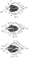


Classifications
-
- A—HUMAN NECESSITIES
- A61—MEDICAL OR VETERINARY SCIENCE; HYGIENE
- A61F—FILTERS IMPLANTABLE INTO BLOOD VESSELS; PROSTHESES; DEVICES PROVIDING PATENCY TO, OR PREVENTING COLLAPSING OF, TUBULAR STRUCTURES OF THE BODY, e.g. STENTS; ORTHOPAEDIC, NURSING OR CONTRACEPTIVE DEVICES; FOMENTATION; TREATMENT OR PROTECTION OF EYES OR EARS; BANDAGES, DRESSINGS OR ABSORBENT PADS; FIRST-AID KITS
- A61F2/00—Filters implantable into blood vessels; Prostheses, i.e. artificial substitutes or replacements for parts of the body; Appliances for connecting them with the body; Devices providing patency to, or preventing collapsing of, tubular structures of the body, e.g. stents
- A61F2/82—Devices providing patency to, or preventing collapsing of, tubular structures of the body, e.g. stents
- A61F2/856—Single tubular stent with a side portal passage
-
- A—HUMAN NECESSITIES
- A61—MEDICAL OR VETERINARY SCIENCE; HYGIENE
- A61F—FILTERS IMPLANTABLE INTO BLOOD VESSELS; PROSTHESES; DEVICES PROVIDING PATENCY TO, OR PREVENTING COLLAPSING OF, TUBULAR STRUCTURES OF THE BODY, e.g. STENTS; ORTHOPAEDIC, NURSING OR CONTRACEPTIVE DEVICES; FOMENTATION; TREATMENT OR PROTECTION OF EYES OR EARS; BANDAGES, DRESSINGS OR ABSORBENT PADS; FIRST-AID KITS
- A61F2/00—Filters implantable into blood vessels; Prostheses, i.e. artificial substitutes or replacements for parts of the body; Appliances for connecting them with the body; Devices providing patency to, or preventing collapsing of, tubular structures of the body, e.g. stents
- A61F2/02—Prostheses implantable into the body
- A61F2/04—Hollow or tubular parts of organs, e.g. bladders, tracheae, bronchi or bile ducts
- A61F2/06—Blood vessels
- A61F2/07—Stent-grafts
-
- A—HUMAN NECESSITIES
- A61—MEDICAL OR VETERINARY SCIENCE; HYGIENE
- A61F—FILTERS IMPLANTABLE INTO BLOOD VESSELS; PROSTHESES; DEVICES PROVIDING PATENCY TO, OR PREVENTING COLLAPSING OF, TUBULAR STRUCTURES OF THE BODY, e.g. STENTS; ORTHOPAEDIC, NURSING OR CONTRACEPTIVE DEVICES; FOMENTATION; TREATMENT OR PROTECTION OF EYES OR EARS; BANDAGES, DRESSINGS OR ABSORBENT PADS; FIRST-AID KITS
- A61F2/00—Filters implantable into blood vessels; Prostheses, i.e. artificial substitutes or replacements for parts of the body; Appliances for connecting them with the body; Devices providing patency to, or preventing collapsing of, tubular structures of the body, e.g. stents
- A61F2/82—Devices providing patency to, or preventing collapsing of, tubular structures of the body, e.g. stents
- A61F2/86—Stents in a form characterised by the wire-like elements; Stents in the form characterised by a net-like or mesh-like structure
- A61F2/90—Stents in a form characterised by the wire-like elements; Stents in the form characterised by a net-like or mesh-like structure characterised by a net-like or mesh-like structure
- A61F2/91—Stents in a form characterised by the wire-like elements; Stents in the form characterised by a net-like or mesh-like structure characterised by a net-like or mesh-like structure made from perforated sheets or tubes, e.g. perforated by laser cuts or etched holes
-
- A—HUMAN NECESSITIES
- A61—MEDICAL OR VETERINARY SCIENCE; HYGIENE
- A61F—FILTERS IMPLANTABLE INTO BLOOD VESSELS; PROSTHESES; DEVICES PROVIDING PATENCY TO, OR PREVENTING COLLAPSING OF, TUBULAR STRUCTURES OF THE BODY, e.g. STENTS; ORTHOPAEDIC, NURSING OR CONTRACEPTIVE DEVICES; FOMENTATION; TREATMENT OR PROTECTION OF EYES OR EARS; BANDAGES, DRESSINGS OR ABSORBENT PADS; FIRST-AID KITS
- A61F2/00—Filters implantable into blood vessels; Prostheses, i.e. artificial substitutes or replacements for parts of the body; Appliances for connecting them with the body; Devices providing patency to, or preventing collapsing of, tubular structures of the body, e.g. stents
- A61F2/82—Devices providing patency to, or preventing collapsing of, tubular structures of the body, e.g. stents
- A61F2/86—Stents in a form characterised by the wire-like elements; Stents in the form characterised by a net-like or mesh-like structure
- A61F2/90—Stents in a form characterised by the wire-like elements; Stents in the form characterised by a net-like or mesh-like structure characterised by a net-like or mesh-like structure
- A61F2/91—Stents in a form characterised by the wire-like elements; Stents in the form characterised by a net-like or mesh-like structure characterised by a net-like or mesh-like structure made from perforated sheets or tubes, e.g. perforated by laser cuts or etched holes
- A61F2/915—Stents in a form characterised by the wire-like elements; Stents in the form characterised by a net-like or mesh-like structure characterised by a net-like or mesh-like structure made from perforated sheets or tubes, e.g. perforated by laser cuts or etched holes with bands having a meander structure, adjacent bands being connected to each other
-
- A—HUMAN NECESSITIES
- A61—MEDICAL OR VETERINARY SCIENCE; HYGIENE
- A61F—FILTERS IMPLANTABLE INTO BLOOD VESSELS; PROSTHESES; DEVICES PROVIDING PATENCY TO, OR PREVENTING COLLAPSING OF, TUBULAR STRUCTURES OF THE BODY, e.g. STENTS; ORTHOPAEDIC, NURSING OR CONTRACEPTIVE DEVICES; FOMENTATION; TREATMENT OR PROTECTION OF EYES OR EARS; BANDAGES, DRESSINGS OR ABSORBENT PADS; FIRST-AID KITS
- A61F2/00—Filters implantable into blood vessels; Prostheses, i.e. artificial substitutes or replacements for parts of the body; Appliances for connecting them with the body; Devices providing patency to, or preventing collapsing of, tubular structures of the body, e.g. stents
- A61F2/82—Devices providing patency to, or preventing collapsing of, tubular structures of the body, e.g. stents
- A61F2/86—Stents in a form characterised by the wire-like elements; Stents in the form characterised by a net-like or mesh-like structure
- A61F2/90—Stents in a form characterised by the wire-like elements; Stents in the form characterised by a net-like or mesh-like structure characterised by a net-like or mesh-like structure
-
- A—HUMAN NECESSITIES
- A61—MEDICAL OR VETERINARY SCIENCE; HYGIENE
- A61F—FILTERS IMPLANTABLE INTO BLOOD VESSELS; PROSTHESES; DEVICES PROVIDING PATENCY TO, OR PREVENTING COLLAPSING OF, TUBULAR STRUCTURES OF THE BODY, e.g. STENTS; ORTHOPAEDIC, NURSING OR CONTRACEPTIVE DEVICES; FOMENTATION; TREATMENT OR PROTECTION OF EYES OR EARS; BANDAGES, DRESSINGS OR ABSORBENT PADS; FIRST-AID KITS
- A61F2/00—Filters implantable into blood vessels; Prostheses, i.e. artificial substitutes or replacements for parts of the body; Appliances for connecting them with the body; Devices providing patency to, or preventing collapsing of, tubular structures of the body, e.g. stents
- A61F2/82—Devices providing patency to, or preventing collapsing of, tubular structures of the body, e.g. stents
- A61F2002/823—Stents, different from stent-grafts, adapted to cover an aneurysm
-
- A—HUMAN NECESSITIES
- A61—MEDICAL OR VETERINARY SCIENCE; HYGIENE
- A61F—FILTERS IMPLANTABLE INTO BLOOD VESSELS; PROSTHESES; DEVICES PROVIDING PATENCY TO, OR PREVENTING COLLAPSING OF, TUBULAR STRUCTURES OF THE BODY, e.g. STENTS; ORTHOPAEDIC, NURSING OR CONTRACEPTIVE DEVICES; FOMENTATION; TREATMENT OR PROTECTION OF EYES OR EARS; BANDAGES, DRESSINGS OR ABSORBENT PADS; FIRST-AID KITS
- A61F2/00—Filters implantable into blood vessels; Prostheses, i.e. artificial substitutes or replacements for parts of the body; Appliances for connecting them with the body; Devices providing patency to, or preventing collapsing of, tubular structures of the body, e.g. stents
- A61F2/82—Devices providing patency to, or preventing collapsing of, tubular structures of the body, e.g. stents
- A61F2/86—Stents in a form characterised by the wire-like elements; Stents in the form characterised by a net-like or mesh-like structure
- A61F2/90—Stents in a form characterised by the wire-like elements; Stents in the form characterised by a net-like or mesh-like structure characterised by a net-like or mesh-like structure
- A61F2/91—Stents in a form characterised by the wire-like elements; Stents in the form characterised by a net-like or mesh-like structure characterised by a net-like or mesh-like structure made from perforated sheets or tubes, e.g. perforated by laser cuts or etched holes
- A61F2/915—Stents in a form characterised by the wire-like elements; Stents in the form characterised by a net-like or mesh-like structure characterised by a net-like or mesh-like structure made from perforated sheets or tubes, e.g. perforated by laser cuts or etched holes with bands having a meander structure, adjacent bands being connected to each other
- A61F2002/9155—Adjacent bands being connected to each other
- A61F2002/91558—Adjacent bands being connected to each other connected peak to peak
-
- A—HUMAN NECESSITIES
- A61—MEDICAL OR VETERINARY SCIENCE; HYGIENE
- A61F—FILTERS IMPLANTABLE INTO BLOOD VESSELS; PROSTHESES; DEVICES PROVIDING PATENCY TO, OR PREVENTING COLLAPSING OF, TUBULAR STRUCTURES OF THE BODY, e.g. STENTS; ORTHOPAEDIC, NURSING OR CONTRACEPTIVE DEVICES; FOMENTATION; TREATMENT OR PROTECTION OF EYES OR EARS; BANDAGES, DRESSINGS OR ABSORBENT PADS; FIRST-AID KITS
- A61F2250/00—Special features of prostheses classified in groups A61F2/00 - A61F2/26 or A61F2/82 or A61F9/00 or A61F11/00 or subgroups thereof
- A61F2250/0004—Special features of prostheses classified in groups A61F2/00 - A61F2/26 or A61F2/82 or A61F9/00 or A61F11/00 or subgroups thereof adjustable
- A61F2250/0013—Special features of prostheses classified in groups A61F2/00 - A61F2/26 or A61F2/82 or A61F9/00 or A61F11/00 or subgroups thereof adjustable for adjusting fluid pressure
Definitions
- the invention relates to a medical device, preferably a stent or flow diverter or, in general, a stent.
- a medical device preferably a stent or flow diverter or, in general, a stent.
- Such medical devices are well known.
- Medical devices of the type mentioned at the beginning are usually used in blood vessels or other body cavities. Further cavities that can be treated with such medical devices are, for example, the esophagus, the intestine, the bile duct, the trachea, the ureter or the like. Such medical devices are often used to treat stenoses, that is to say vascular constrictions of the blood vessels, in particular the coronary vessels, the larger arteries and / or the cerebral vessels. Another possible application for the use of such known medical devices is the treatment of aneurysms, that is to say vascular sacs. A blood vessel forms a local expansion, whereby the vessel wall is strongly stretched and stressed in this area. There is a risk that the stretched vessel wall will tear, which can lead to bleeding.
- vascular supports usually have a lattice structure that is used to feed the vascular support into a blood vessel to a smaller cross-sectional diameter can be compressed.
- the stent expands or expands and exerts a radial force on the vessel wall.
- vascular constrictions can be widened.
- the stent can expand by expanding a balloon to which the stent is attached. To do this, the balloon is filled with a liquid via a catheter.
- the lattice structure of the stent can expand automatically.
- Such vascular supports usually have a shape memory material that assumes the previously determined shape at body temperature.
- the lattice structure of the known vascular supports has cells or meshes, the size of which varies depending on the intended use.
- vascular supports are used whose lattice structure has a relatively small mesh or cell size. What is achieved thereby is that the blood flow within the aneurysm is stopped or at least reduced, so that further loading of the vessel wall within the aneurysm is avoided.
- An alternative treatment method for aneurysms consists in inserting individual thin wire elements into the aneurysm, which curl chaotically in the aneurysm and thus block the blood flow or the blood flow within the aneurysm.
- coils When using such wire elements, so-called coils, there is a risk that the coils will protrude at least in sections from the aneurysm into the blood vessel and affect the blood flow within the blood vessel, so that clots, in particular thrombi, can form within the blood vessel.
- the coils themselves can also be washed out of the aneurysm and cause a vascular occlusion in downstream blood vessels.
- the blood vessel is first stabilized with a stent in the area of the aneurysm. Subsequently, coils are introduced into the aneurysm through the meshes or cells of the stent. The choice of the mesh size of the stent is decisive.
- a vulnerable plaque is an accumulation of fat particles and body cells within a blood vessel that is covered by a thin vascular lining.
- the blood vessel cross-section is narrowed by the vulnerable plaque, so that the stenosis forms.
- a stenosis is widened by a vascular support with a lattice structure, there is a risk that the webs of the lattice structure injure the inner vascular skin and thus particles are released into the blood flow. The released particles can cause vascular occlusion in downstream blood vessels.
- vascular supports comprise a flexible film which completely spans the lattice structure.
- the film prevents detached particles from moving into the bloodstream and being washed away.
- stenoses occur in the area of branching vessels, for example in the area of the mouth of the vertebral artery into the basilar artery or when the common carotid artery is divided into the internal carotid artery (internal carotid artery) and the external carotid artery (external carotid artery) ) on.
- the use of vascular supports with a closed film is not possible in such areas, since the blood flow into the branching blood vessel would be interrupted.
- vessel supports without a film have the disadvantages mentioned above with regard to particle detachment.
- foil-covered vascular supports for the treatment of aneurysms has essentially the same disadvantages as described above with regard to the known flow diverters, which have a relatively small mesh size. Both with the known flow diverters and with vascular supports covered with foil, it is not possible to insert a catheter into the aneurysm for feeding coils.
- WO 2008/057568 A1 discloses a stent with a flexible covering (graft) that completely covers the stent. Flaps are formed in the cover.
- WO 2010/048177 A2 shows a stent in which a large window is formed, which is intended to allow access to an aneurysm for the introduction of coils.
- WO 2007/117645 A2 discloses an occlusion system for aneurysms.
- the closure system comprises a tubular stent with several struts which delimit large-area cells.
- Several flaps are arranged in the cells, which can be moved into an open and closed position.
- the valves are not connected directly to the stent structure, but rather via an additional side strut. This has the disadvantage that the valve can only cover the opening formed in the stent structure over a comparatively small area.
- the side strut appears not very stable, which is viewed as disadvantageous with regard to the pressure fluctuations occurring in the pulsating blood flow.
- the object of the invention is to provide a medical device which, on the one hand, enables reliable support of a body cavity and, on the other hand, enables a lateral fluid flow.
- the object of the invention is to provide a medical device with which a fluid flow within a body cavity can be controlled over time in a targeted manner.
- the invention is preferably intended to provide a medical device which reliably covers a stenosis and / or an aneurysm and at the same time enables a lateral fluid flow in the area or in the vicinity of the stenosis or the aneurysm.
- the invention is based on the object of specifying a medical device which prevents an axial fluid flow counter to the main flow direction of the fluid guided within the body cavity and enables a fluid flow in the main flow direction of the body fluid.
- this object is achieved with regard to the lateral fluid flow through the subject matter of claim 1 and with regard to the axial fluid flow through the subject matter of patent claim 2.
- the invention is based on the idea of specifying a medical device with a tubular wall made of webs that delimit cells and a flexible membrane that forms at least one valve.
- the flap has a first end which is connected to at least a first web of a cell. Furthermore, the flap has a free second end which is arranged opposite the first end in the longitudinal direction of the flap.
- the flap can be moved into a closed position and an open position. In the closed position the flap extends along the tubular wall and at least partially closes the cell. In the open position, the flap is deflected radially relative to the wall in order to release the cell like a valve.
- the invention is based on the idea of covering the cells of the tubular wall with a flexible membrane which is designed like a flap.
- the flap-like membrane or the flap can be deflected radially in order to cover the cell in the closed position and to release the cell opening in the open position.
- the flap thus has a valve function.
- the flap automatically assumes its closed or open position, specifically as a result of a pressure gradient or a fluid flow.
- the pressure gradient or the fluid flow can be formed between an inner hollow channel, which extends in the axial direction inside the tubular wall, and an outer space, which extends outside, in particular radially outside, the tubular wall.
- the closed position or the open position of the flap can be adjusted by manual actuation.
- the flap can be opened by the action of an external force, preferably by the pushing force of a catheter.
- the flap enables the cell to be reliably covered in the closed position, for example in order to block blood flow into an aneurysm.
- the flap can be moved into the open position so that, for example, coils can be inserted into an aneurysm.
- the valve closes the cell or cell opening automatically. This also prevents coils from entering the bloodstream from the aneurysm.
- the flap rests completely on the tubular wall in the closed position.
- the flap thus extends essentially parallel along the tubular wall and that essentially in complete contact with the tubular wall.
- the flap can also be arranged in the closed position or have the closed position when the flap is slightly deflected with respect to the tubular wall. This applies in particular when the medical device is in the manufacturing state or when it is inactive. in the In the manufacturing state of the medical device, the flap can thus be deflected slightly radially outward or radially inward, advantageously avoiding a significant opening of the cell.
- This basic deflection which is present in the closed position, can be impressed on the flap, for example by means of a heat treatment.
- the basic deflection can be adapted in such a way that the valve in the implanted state, for example by resting against a vessel wall, can be arranged so that it rests parallel and flush on the tubular wall.
- the flush contact of the flap against the tubular wall in the implanted state can also be achieved by the influence of a fluid flow which acts on the flap.
- the deflection for producing the open position of the flap is significantly greater than the basic deflection in the closed position of the flap. The valve function of the flap comes into play when the flap is moved from the closed position to the open position and vice versa.
- aneurysms in particular can be reliably covered, and at the same time it is possible to feed coils into the aneurysm.
- the distances between the webs of the tubular wall that is to say the cell size, can be selected to be comparatively large in order to guide a catheter through the tubular wall.
- the medical device has improved crimpability, that is to say a relatively small cross-sectional diameter in the compressed state, since the number of webs in the circumferential direction of the tubular wall is reduced. At the same time, the flexibility of the device is increased by the small number of webs.
- the medical device according to the invention is particularly advantageous in the case of aneurysms which are formed in the area of vascular branches.
- the flexible flap enables the aneurysms to be reliably covered so that an advantageous embolization occurs within the aneurysm, so that the blood flow and thus the loads on the vessel wall within the aneurysm are reduced.
- the valve or another valve can be transferred from the closed position to the open position through the blood flow that flows into the lateral vessel in which the aneurysm is formed in the area of the vascular branching, so that a natural flow passage is formed in which the Blood or in general the body fluid can flow past the aneurysm into the lateral vessel.
- the flap is connected on one side, namely at the first end, to a web of the tubular wall.
- the second end is arranged freely or loosely.
- the second end is opposite the first end in the longitudinal direction of the flap.
- the free second end is therefore movable relative to the first end.
- the flexible membrane that forms the at least one flap enables particles transported with the fluid flow to be guided in a preferred direction.
- the flexible flap in the area of branching vessels enables fluid to flow into a laterally branching vessel.
- the flexible flap can prevent the particles, for example thrombus components, from flowing into the lateral vessel. In this way, the particles can be guided into areas of the body in which a vascular occlusion leads to comparatively minor health impairments.
- the invention is based on the idea of specifying a medical device, in particular a stent, with a tubular wall that forms an axial hollow channel and has webs that delimit cells.
- a medical device in particular a stent
- a tubular wall that forms an axial hollow channel and has webs that delimit cells.
- at least two flexible membranes are provided which are arranged at a distance from one another in the longitudinal direction of the axial hollow channel.
- the flexible membranes each form at least one flap.
- the flap has a first end which is connected to at least a first web of a cell.
- the flap has a free second end which is arranged opposite the first end in the longitudinal direction of the flap.
- the flap can be moved into an open position and into a closed position. In the open position, the flap extends along the tubular wall. In the closed position, the flap is radially deflected relative to the wall and protrudes into the axial hollow channel in order to at least partially close the axial hollow channel like a
- the secondary aspect of the invention provides for the axial hollow channel to be temporarily closed by at least two axially spaced apart flaps.
- the flap is firmly connected at a first end to a web of the tubular wall.
- the free second end is movable relative to the first end, in particular can be deflected in the radial direction with respect to the tubular wall.
- the flap closes the axial hollow channel.
- the medical device according to the secondary aspect of the invention has the advantage that the function of venous valves is simulated by the at least two valves, which on the one hand are axially spaced apart and on the other hand at least partially close the axial hollow channel in the closed position.
- the flaps are therefore preferably adapted in such a way that the flaps can each be transferred from the closed position into the open position as a result of a fluid flow through the axial hollow channel.
- the flaps are preferably aligned or adapted in such a way that a fluid flow in a first axial direction transfers the flap from the closed position into the open position.
- a fluid flow in a second axial direction opposite to the first axial direction advantageously brings about the transfer of the flap from the open position to the closed position.
- the flaps thus enable the fluid flow through the axial hollow channel to be influenced in such a way that the fluid flow is possible in a single direction. Fluid flow in the opposite direction is blocked.
- the flaps can also be transferred manually from the closed position to the open position.
- the two membranes arranged at a distance in the axial direction mean that the medical device can be used as a venous valve prosthesis, at least two venous valves being replaceable at the same time.
- the medical device can also be used as a full-fledged vascular replacement or as a full-fledged vascular prosthesis.
- the flaps can be arranged on an inner circumference of the tubular wall and the outer circumference of the tubular wall can be enclosed with a film known per se, so that a tube-like vascular prosthesis is formed with a support structure made of webs and an axial hollow channel closing flaps.
- the flap can partially protrude radially into the hollow channel in the open position. This ensures that the flap automatically assumes the closed position when a fluid flow acts on the membrane against the first axial direction.
- the cell has at least one first node which connects the first web to a second web.
- the first web and the second web enclose an angle in the area of the junction.
- the first end of the flap is connected in the vicinity, in particular in the region of the first node, to the first web and / or the second web.
- the arrangement of the first end of the flap in the area or in the vicinity of a first node ensures that sufficient coverage of the cell is ensured when the tubular wall is in an expanded state. At the same time, excessive stretching of the flexible membrane, in particular the flap, is avoided during the transition from the compressed state of the tubular wall to the expanded state.
- the first end of the flap can be arranged on an outer circumference or an inner circumference of the tubular wall.
- the membrane can be arranged on the outer circumference or the inner circumference of the tubular wall.
- the arrangement of the membrane or the first end of the flap on the outer circumference of the tubular wall has the advantage that a relatively uniform, smooth and flat outer skin is formed on the outer circumference. Such a configuration is advantageous, for example, in the treatment of stenoses, in particular in the case of vulnerable plaques, since the smooth outer skin avoids injury to the vulnerable plaque.
- the advantage of arranging the flexible membrane or the first end of the flap on the inner circumference of the tubular wall is the improved adhesion or fixation of the medical device in a hollow body vessel.
- the on the outer circumference of the tubular wall formed webs a lattice structure which is easily pressed into, preferably healthy, vessel walls and thus fixes the medical device.
- the flexible membrane forms a uniform inner skin, at least in the closed position of the flaps, so that a flow-optimized hollow channel is formed.
- the comparatively smooth and uniform inner skin prevents thrombogenization in the area of the medical device and thus restenosis.
- the flap can have a substantially sheet-like shape.
- a substantially sheet-like shape enables the cells or the axial hollow channel to be reliably covered.
- the sheet-like shape enables a particularly advantageous folding of the flap when the tubular wall or, in general, the medical device is transferred from the expanded state to the compressed state.
- the leaf-shaped shape of the flap therefore ensures that the tubular wall can be compressed to a relatively small cross-sectional diameter.
- the flap preferably has a structure, in particular a pore structure or a groove structure or a fleece structure.
- the structuring of the valve enables endothelialization. This means that endothelial cells can attach to the valve due to the structure. Rapid accumulation of endothelial cells is desirable, as this reduces the risk of thrombosis or restenosis.
- the structuring can also ensure that smaller secondary vessels are exposed to a fluid flow, the fluid flow being possible through the structuring of the flap. This is particularly advantageous if the cross-sectional diameter of the secondary vessel is smaller than the longitudinal or circumferential extent of the valve.
- the structuring increases the flexibility of the flap or counteracts material stresses in the flap, which are triggered, for example, by an expansion of the flap.
- the flap has a fold line which extends at least in sections from the first end to the free second end.
- the fold line indicates a preferred fold.
- the fold line preferably runs in the longitudinal direction of the flap. It is particularly advantageous if the fold line is adjacent to two in the longitudinal direction of the tubular wall arranged nodes is aligned. It is thereby achieved that the flap preferably folds radially through the cell when the medical device is transferred from the expanded state to the compressed state. This enables a particularly small, compressed form of the medical device.
- the fold line can subdivide the flap into a first flap wing and a second flap wing.
- the first valve wing is preferably connected to the first web of the cell and the second valve wing is connected to the second web of the cell. This will ensure that the flap folds evenly along the fold line.
- the fold line can comprise a groove and / or a gap so that the folding of the flaps is facilitated when the medical device is transitioned from the expanded state to the compressed state.
- the gap can separate the first flap wing at least in sections from the second flap wing.
- the first flap wing can be connected to the second flap wing or formed in one piece, with a section being provided between the first flap wing and the second flap wing which includes the gap. In the region of the gap, the first flap wing and the second flap wing are arranged at a distance from one another.
- the gap is preferably arranged in the longitudinal direction of the flap.
- the gap can be open in the direction of the first node, in the vicinity of which the first and second flap wings are connected to a first and second web, respectively.
- the gap can completely separate the first flap wing from the second flap wing, so that the first flap wing is arranged at a complete distance from the second flap wing.
- the flap forms two individual flap parts, namely the first flap wing and the second flap wing. In this way, the folding or the arrangement of the flap in the compressed state of the medical device is further improved. Furthermore, by dividing the flap into two separate flap wings, the transition from the closed position to the open position is facilitated. Overall, the valve function can thus be improved.
- the flap can be automatically transferred from the closed position to the open position.
- the free end of the flap can protrude into the cell in the closed position, in particular within the cell be arranged, or overlap the cell.
- the cells overlap at least in the longitudinal direction of the medical device. This means that partial areas of the cell in the circumferential direction of the tubular wall cannot be covered by the flap.
- the flap overlaps the cell the free end of the flap extends in the longitudinal direction or axial direction of the tubular wall beyond the cell. The overlap ensures that the cell is reliably covered in the expanded state of the tubular wall or, in general, of the medical device, when the flap has assumed the closed position.
- the cell can be partially uncovered in the expanded state of the tubular wall or the medical device.
- the flap it is possible for the flap to extend in the closed position in the longitudinal direction or in the circumferential direction of the tubular wall.
- the extension of the flap in the closed position in the longitudinal direction or axial direction of the tubular wall is particularly preferred.
- the membrane has several flaps.
- the plurality of flaps In the closed position, the plurality of flaps extend along the tubular wall.
- a free end of a first flap overlaps at least one, in particular two, first ends of an adjacent flap like a roof tile.
- the tile-like overlap of the flaps can be seen at least in a compressed state of the tubular wall or, in general, of the medical device.
- the tile-like overlap is also set in the expanded state of the tubular wall.
- the tile-like overlap can occur at least in the circumferential direction in the compressed state of the tubular wall.
- at least one first flap overlaps at least one second flap, preferably two second flaps.
- the first flap can extend in the longitudinal direction of the tubular wall, wherein the second, free end extends essentially between two second flaps arranged adjacent to the tubular wall in the longitudinal direction.
- the medical device comprises a plurality of rows of valves arranged adjacent to the tubular wall in the axial direction, the valves in each case are arranged directly offset from one another in the axial direction of successive rows.
- the first flaps of a first row thus each overlap two second flaps of a second row.
- the second, free ends of the first flaps of a first row in the compressed state of the tubular wall overlap two first, fixed ends of two second flaps of a second row.
- the second, free ends of the first flaps of a first row can overlap two second, free ends of two second flaps of a second row.
- the flaps of adjacent rows can be arranged in opposite directions.
- the first row and the second row of flaps in this case extend in the longitudinal direction.
- the first flaps of the first row overlap at least one, in particular two second flaps of a second row of flaps arranged adjacent in the circumferential direction.
- the first flaps of the first row can at least partially overlap the cells of the second row.
- the first flaps of the first row can extend between two second flaps of the second row.
- the at least two membranes each form a multiple valve.
- the multiple flap can be moved from a closed position to an open position.
- the multiple flap preferably has at least two flaps which are arranged radially opposite one another in relation to a longitudinal axis of the axial cavity. In the closed position, the at least two flaps extend into the axial cavity in order to close the axial cavity in the manner of a valve.
- the multiple flap is particularly advantageous.
- the free, second ends of the flaps of the multiple flap can touch in the closed position. This ensures that the axial cavity is securely closed.
- the axial cavity is preferably closed in a fluid-tight manner in the closed position of the multiple flap or, in general, of the flap.
- a cell has two flaps, which in an expanded state of the cell in opposition and in a compressed state of the Cell are arranged side by side.
- this arrangement has the advantage that a large area of the cell is covered without the cell being too long.
- the advantage is that the crimping is simplified, since the cover or the flaps overlap with the structure and not with each other during crimping.
- a pore structure in particular a perforation of the flap, is formed at least in the area of the first end of the flap, which extends into the area of the first web, the first end being connected in sections to the first web such that the pore structure of the first end is deformable in the loose area or in the loose areas. Deformation of the cover or the flap is thereby avoided or at least reduced.
- FIG. 1 shows the expanded state of a tubular wall 10 or, in general, of the medical device. The same applies to all the exemplary embodiments that are shown in Figures 1 to 17c are shown.
- the tubular wall 10 or the section of the tubular wall 10 is shown in FIG Fig. 1 shown in the unfolded or flat-out state.
- the axial longitudinal axis of the tubular wall 10 runs in the Fig. 1 , 2 , 3 , 7th and 10 to 15 essentially horizontal in the plane of the drawing.
- the detailed section of the wall 10 in Fig. 1 shows several webs 11 which each connect two nodes 13 to one another.
- the webs 11 are S-shaped.
- Four webs 11 are connected to one another in a node 13.
- Four webs 11 each delimit a cell 12 of the tubular wall 10.
- the cells 12 are completely delimited by webs 11.
- the tubular wall 10 according to Fig. 1 therefore forms a closed cell structure.
- the tubular wall 10 has an open-cell structure, with at least two webs 11 in a node 13 being freely movable, that is, not connected to one another.
- the webs 11 can in this case form end bends which can change their position relative to the lattice structure when the tubular wall or generally a lattice structure formed by the webs 11 is transferred from the compressed state to the expanded state.
- the closed-cell structure is preferred for the exemplary embodiments described in this application.
- the webs 11 form the lattice structure or the tubular wall 10.
- the medical device has a carrier structure or support structure, which is formed by the webs 11 connected at the nodes 13.
- the cells 12 each include a first web 11a and a second web 11b, the first and second webs 11a, 11b being connected to one another at a first node 13a.
- the first web 11a and the second web 11b extend from the first node 13a to a second node 13b each, the nodes 13a and 13b being arranged in the longitudinal direction of the tubular wall 10 adjacent and offset in the circumferential direction. This applies in particular in the expanded state of the tubular wall 10.
- the close first web 11a and second web 11b an angle.
- the first nodes 13a of adjacent cells 12 are aligned with one another. This applies both to the longitudinal direction of the tubular wall 10 and to the circumferential direction. The same applies to the second nodes 13b of respectively neighboring cells 12.
- the tubular wall 10 also has a flexible membrane 20.
- the flexible membrane forms at least one flap 21.
- the flap 21 comprises a first end 22a which is connected to the first web 11a and the second web 11b.
- the first end 22a is preferably cohesively connected to the first web 11a.
- the connection to the second web 11b is preferably also made with a material fit.
- the first end 22a of the flap 21 is arranged in the vicinity of a node 13, in particular the node 13a.
- all points of a web 11 which are at a distance from the node 13 that corresponds at most to half the length of the web 11 are viewed as points or areas that are located in the vicinity of the node 13 .
- the distance refers to the distance between the point to be determined and the junction 13 along the web 11. In other words, half of the web 11 that faces the junction 13 or is connected to another web 11 at the junction 13 belongs, the proximity of this junction 13.
- the flap 21 also has a free, second end 22b which is arranged opposite the first end 22a in the longitudinal direction of the flap 21.
- the flap 21 extends in the embodiment according to Fig. 1 in the longitudinal direction of the tubular wall 10.
- the first end 22a and the second end 22b of the flap 21 are arranged downstream of one another.
- the flap 21 is aligned with the first node points 13a of adjacent cells 12, which are arranged downstream in the longitudinal direction of the wall 10.
- the flap 21 has a substantially sheet-like shape.
- the second free end 22b in particular forms a curved free edge 22c of the flap 21.
- the free edge 22c extends over the free, second end 22b and is delimited by the first and second webs 11a, 11b.
- the shape of the free edge 22c between the first web 11a and the second web 11b essentially corresponds to an omega.
- the first end 22a comprises two holding sections 22d, which are each connected to the first web 11a or the second web 11b.
- An inner edge 22e is formed between the holding sections 22d in the region of the first end 22a. The inner edge 22e extends along the holding sections 22d from the first web 11a to the second web 11b.
- the inner edge 22e in each of the two holding sections 22d has an opposite curvature.
- the inner edge 22e thus forms an incision in the form of a tent roof in the flap 21.
- the inner edge 22e encloses a folding opening 29.
- the folding opening 29 essentially has the shape of a dragon square or deltoid with inwardly curved side edges. The longer diagonal of the kite square extends in the longitudinal direction of the flap 21 or the tubular wall 10.
- the flap 21 extends into the cell 12 in the closed position. This means that the flap 21 partially covers the cell 12 in the closed position.
- the flap 21 covers a central area of the cell 12.
- the flap 21 can be shaped in such a way that the cell 12 is completely covered in the closed position of the flap 21 and in the expanded state of the tubular wall 10.
- the folding opening 29 can also be covered by the membrane 20 or the flap 21.
- FIG Fig. 2 Another embodiment of the medical device in which the flap 21 covers a larger area of the cell 12 is shown in FIG Fig. 2 shown.
- the embodiment according to Fig. 2 corresponds essentially to the embodiment according to Fig. 1 , wherein the flap 21 has a comparatively larger longitudinal extension and the cell 12 overlaps.
- the second, free end 22b of the flap 21 is arranged in the closed position in the region of the node 13, in particular the first node 13a of an adjacent cell 12, resting on the webs 11.
- the flap 21 thus overlaps the cell 12.
- the membrane 20 on areas of the first web 11a and the to expand second web 11b, which are arranged away from the first node 13a.
- the membrane 20 forms a wing-like widening along the web 11.
- the wing-like widening itself is shown in German patent no. 10 2008 010 507 described in detail, which goes back to the applicant.
- a combination of the medical device with the wing-like widenings of the webs 11 described therein is hereby explicitly disclosed.
- the membrane 20 can be arranged on the outer circumference 14 a of the tubular wall 10.
- the flaps 21 extend over the outer circumference 14a.
- the membrane 20 can be arranged on an inner circumference 14d of the tubular wall 10.
- the flaps 21 extend along the inner circumference 14b.
- the flaps 21 can extend in the longitudinal direction of the wall 10. It is also possible for the flaps 21 to extend in the circumferential direction of the wall 10.
- the flaps 21 can each extend in the same direction. This means that, in the closed position, a free, second end 22b of a first flap 21a is aligned with or overlaps a fixed first end 22a of a second flap 21b.
- the flaps 21 of adjacent cells 12 can be arranged in opposite directions.
- a first flap 21a and a second flap 21b adjacent in the longitudinal direction of the first flap 21a can each have a free second end 22b, the free second ends 22b being arranged adjacent to one another or overlapping one another.
- the flaps 21 and the membrane 20 are flexible.
- the flaps 21 are flexible in such a way that the second, free end 22b of the flap 21 can be radially deflected relative to the first, fixed end 22a.
- the flap 21a is so flexible that the flap 21a can be moved into an open position in which the flap 21 does not cover the cell 12. In the open position of the flap 21, the cell 12 is essentially freely accessible.
- the flap 21, in particular the second free end 22b is deflected in the open position or is bent in the radial direction with respect to the tubular wall 10.
- the flap 21 can be curved outwards as well as inwards.
- the free end 22b points either radially outwards or radially inwards with respect to the tubular wall 10. It is irrelevant whether the flap 21 is arranged with the first end 22a on the outer circumference 14a or on the inner circumference 14b of the tubular wall is.
- the flap 21 is preferably adapted in such a way that it is deflected radially outward when the first end 22a of the flap 21 is connected to the outer circumference 14a of the tubular wall 10.
- the flap 21 is preferably adapted in such a way that a deflection occurs radially inward with respect to the tubular wall 10 when the flap 21 is arranged with the first end 22a on the inner circumference of the tubular wall 10.
- the medical device comprises two main functional elements.
- a load-bearing structure in particular in the form of the tubular wall 10, which preferably comprises a lattice structure of webs 11, is provided, which ensures the stability or force in the radial direction.
- the supporting structure can essentially have a stent-like geometry.
- the medical device has a cover, in particular in the form of the membrane 20, which forms flaps 21.
- the flaps 21 protrude into the cells 12 or overlap them. In the closed position, the cell 12 is at least partially, in particular completely, covered by the flap 21.
- the flexible flap 21 has a valve function.
- the flap has the first fixed end 22a and the second free or loose end 22b.
- the function of the membrane 20 or the flap 21 is in particular to release the cell 12 in the manner of a valve.
- the release can in particular be brought about by a pressure gradient that is established between the sides of the cell, in particular an inner axial hollow channel 30 of the tubular wall 10 or the medical device, and an area radially outside of the tubular wall 10.
- the flexible flap 21 can be moved into the open position or closed position in that a fluid flow acts on the flap 21.
- a high flexibility of the flap 21 is advantageous.
- the flap 21 can essentially be designed as a film.
- the wall thickness of the flap 21 can be comparatively small.
- the comparatively small wall thickness enables not only an improved or easier valve function, but also an improvement in the crimping of the tubular wall 10, since the relatively thin flap 21 folds into the cell 12 and the thin wall thickness ensures that a relatively small crimped cross-sectional diameter for the tubular wall 10 can be achieved.
- the membrane 20, in particular the flap 21 has a wall thickness that is at most 15 ⁇ m, in particular at most 10 ⁇ m, in particular at most 8 ⁇ m, in particular at most 6 ⁇ m, in particular at most 4 ⁇ m, in particular at most 2 ⁇ m, in particular at most 3 ⁇ m, in particular at most 2 ⁇ m.
- the relatively small wall thickness of the flap 21 also makes it possible for the flap 21 to flutter when a body fluid, in particular blood, flows through the cell 12.
- turbulent flow conditions can advantageously form in the area of the flap 21, so that, for example, blood congestion is avoided or blood clotting, in particular thrombogenization, is counteracted. Rather, the fluttering of the flap 21 achieves a constant, continuous flow in the open position.
- the flap 21 extends or covers the entire cell 12. At least the flap 21 covers at least 10%, in particular at least 20%, in particular at least 30%, in particular at least 40%, in particular at least 50%, in particular at least 60%, in particular at least 70%, in particular at least 80%, of the cell 12 in the expanded state.
- the largest possible circle diameter that can be seen in an area released by the flap 21 is at most 80%, in particular at most 60%, in particular at most 40%, in particular at most 30%, in particular at most 20%, in particular at most 10%, of the size of the cell 12, the size of the cell 12 corresponding to the diameter of the largest possible circle that can be arranged in the cell 12.
- the flap 21 can also have a structure, in particular a surface structure, which, for example, promotes the endothelialization of the medical device.
- the structuring can include a pore structure 28, for example.
- the structuring can have a plurality of openings which are introduced into the flap 21 and completely penetrate the flap 21 in the radial direction in relation to the lattice structure 10.
- the distance between two nodes arranged adjacent in the longitudinal direction of the medical device changes when the state of the wall 10 changes, that is to say the wall 10 changes from the radially compressed to the radially expanded state and vice versa.
- the transition from the radially expanded to the radially compressed state of the wall 10 causes an extension of the distance between nodes 13, 13a arranged adjacent in the longitudinal direction of the medical device.
- the S-shaped webs 11 can deform, which can lead to an expansion of the flap 21.
- the structuring, in particular the pattern-like pore structure 28, facilitates the expansion or the opening of the flap 21.
- the pore structure 28 prevents stresses occurring in the flap 21 or in general the membrane 20.
- the pore structure 28 preferably has pores which are diamond-shaped.
- the diamond-shaped pores advantageously comprise two oppositely arranged corners which have a relatively large angle.
- the angle can be at least 90 °, in particular at least 120 °, in particular at least 130 °, in particular at least 140 °, in particular at least 150 °, in particular at least 160 °, in particular at least 170 °.
- the corners with the larger corner angle are preferably arranged opposite one another in the circumferential direction of the tubular wall 10.
- the pores of the pore structure 28 are preferably arranged in a pattern-like manner, that is to say regularly, distributed over the flap 21, for example in the Figures 14 and 15 shown.
- the pores of the pore structure 28 can also be slit-shaped.
- the corner angles of the pores arranged opposite one another in the circumferential direction of the tubular wall 10 are therefore almost 180 ° or exactly 180 °.
- the gap width of the slot-shaped pores can be at most 300 ⁇ m, in particular at most 200 ⁇ m, in particular at most 100 ⁇ m, in particular at most 50 ⁇ m.
- the relatively large angle of the oppositely arranged corners of the pores of the pore structure 28 results in a particularly great flexibility of the flap 21 or, in general, of the membrane 20. An expansion of the membrane 20 or the flap 21 is thus effectively avoided or at least reduced.
- the pore structure 28 described above can be combined with all exemplary embodiments.
- the flap 21 is generally so flexible that in the open position a deflection is made possible that is at least 20 °, in particular at least 30 °, in particular at least 45 °, in particular at least 60 °, in particular at least 90 °, in relation to the closed position.
- the deflection takes place in the elastically deformable area of the flap 21.
- the flap 21 is curved.
- the maximum radius of curvature or the radius of the curvature at the most strongly curved point of the flap 21 is preferably at most 2 mm, in particular at most 1.5 mm, in particular at most 1 mm, in particular at most 0.8 mm, in particular at most 0.6 mm, in particular at most 0.4 mm, in particular at most 0.2, in particular at most 0.1 mm, in particular at most 0.05 mm.
- the flap 21 is preferably so flexible that it can be deflected to different extents depending on the physiological conditions at the treatment site.
- the flap 21 can have different geometries, as shown below with reference to FIG Figs. 10-14 is explained: In the Figs. 10-14 each a single cell 12 of a medical device according to a preferred embodiment is shown.
- the medical device can have at least one cell 12 which is provided with a flap 21 according to one of the exemplary embodiments according to FIGS Figs. 10-14 is trained. It is also possible for the medical device to have a plurality of cells 12 which include differently designed flaps 21.
- the medical device or the wall 10 can have any combination of cells according to the Figs. 10-14 exhibit.
- the wall 10 preferably has several cells of the same type. In particular, it is provided that the Figs.
- flaps 21 are present several times in a tubular wall 10 and are connected to one another.
- the flaps 21, which are present several times in the wall 10 and are adjacent to one another, are preferably connected to one another in such a way that the flaps 21 together form a single membrane 20.
- the wall 10 preferably has a single membrane which forms a plurality of flaps 21.
- the flaps 21 can be arranged in immediately adjacent cells 12. It is also possible for the flaps 21 to be arranged in such a manner distributed over the wall 10 of the medical device are that at least between individual flaps 21 free cells 12 are arranged.
- the membrane is connected to the support structure or the webs 11 essentially at points.
- the punctiform connection between the membrane 20 and the webs 11 is preferably made at the points which each form the first end 22a of a flap 21.
- the connection of the membrane 20 takes place essentially in the vicinity or in the vicinity of a node 13.
- the membrane 20 or the flap 21 is preferably connected at the points of the webs or the wall 10 which are in the Make a comparatively small movement to transition the medical device from the compressed state to the expanded state.
- the connection of the flap 21, in particular the first end 22a, directly in the node area 13, which is essentially not deformed during the expansion of the medical device, is particularly preferred.
- At least the flap 21 is arranged between the first web 11a and the second web 11b in the vicinity of the node 13.
- the first web 11a and the second web 11b form an acute angle.
- a comparatively small relative movement takes place in the area of the acute angle between the first web 11a and the second web 11b.
- the first end 22a of the flap 21, as in FIG Figs. 10-14 shown is attached to a region of the webs 11 which is curved in the direction of the flap 21 or in the direction of the center of the cell 12. What is achieved thereby is that when the medical device is compressed or crimped, the flap 21 is caused to fold. An expansion, that is to say the generation of tension within the flap 21 when the medical device is compressed, is thus avoided.
- the geometry of the cell 12 and the flap 21 according to FIGS Figures 10 and 11 corresponds essentially to the geometry of the cells 12 and the flaps 21 according to FIG Fig. 1 and 2 .
- a difference from the exemplary embodiments according to Fig. 1 and 2 consists in that the leaf-like shape of the flap 21 comprises a flatter free edge 22c in the direction of the second end 22b.
- the free edge 22c according to Fig. 10 is essentially parabolic. This means that the free edge 22c, starting from the first web 11a to the second web 11b, has essentially a uniform curvature in the clockwise direction, the radius of curvature varying. The same is essentially true of that Embodiment according to Fig.
- FIG. 11 wherein a front portion of the free edge 22c in the area of the second end 22b in comparison to the embodiment according to FIG Fig. 10 is flatter. Furthermore, the lateral sections of the free edge 22c, which extend between the second, free end 22b of the flap 21 and the first and second webs 11a, 11b, are shown in FIG Fig. 10 more arched or curved outwards.
- the exemplary embodiments according to FIG Figures 10 and 11 in that the flap 21 according to Fig. 10 extends into the cell, whereas the flap 21 according to FIG Fig. 11 extends beyond cell 12 or overlaps cell 12.
- the second end 22b of the flap 21 is arranged completely within the cell 12. In Fig. 11 it can be seen that the second end 22b of the flap 21 protrudes over the further webs of the cell 12. In the closed position, the flap 21 rests loosely or freely, in particular unconnected, on the further webs 11.
- the inner edge 22e of the flap 21 has a curvature directed towards the first node 13a.
- the curvature of the inner edge 22e runs from the first web 11a to the second web 11b uniformly or continuously in the counterclockwise direction.
- An incision in the flap 21 is made with the inner edge 22e according to FIG Figures 10, 11 and 14th not educated.
- the folding opening 29 formed by the first web 11a, the second web 11b and the inner edge 22e of the flap 21 essentially has a funnel-like shape.
- the flap 21 can have a fold line 23 which extends essentially in the longitudinal direction of the flap 21.
- the fold line 23 is aligned with two node points 13 which are arranged downstream of one another or are arranged in alignment with one another in the longitudinal direction or axial direction of the tubular wall 10.
- the fold line 23 is aligned with two first nodes 13a of two cells 12 which are directly adjacent in the longitudinal direction of the wall 10.
- the fold line 23 can, as in FIG Fig. 12 comprise a groove 23a.
- the groove 23a is preferably adapted in such a way that folding of the flap 21 when the tubular wall 10 is compressed is facilitated.
- the groove 23a provides a defined folding edge which essentially serves as an axis of rotation around which a first flap wing 24a and a second flap wing 24b of the flap 21 can be rotated for folding.
- the first flap wing 24a and the second flap wing 24b are so in the Compression of the tubular wall 10 along the fold line 23, in particular the groove 23a, folded over one another.
- the groove 23a can be produced, for example, by an etching process.
- the groove 23a preferably has a depth which corresponds to at least 25%, in particular at least 30%, in particular at least 40%, in particular at least 50%, in particular at least 60%, in particular at least 70%, in particular at least 75%, of the wall thickness of the flap 21 . It is also possible for several grooves 23a to be provided which extend over the flap 21 in different orientations. In this way, the folding of the flap 21 can be made possible in complex geometries.
- the groove 23a extends in a straight line over the flap 21.
- the groove 23a can also extend over the flap 21 in a different orientation, in particular in an alternating orientation.
- valve wings 24a, 24b fold radially inward when the tubular wall 10 is compressed, in order to facilitate the arrangement of the medical device in a catheter 60.
- the flap 21 can have a plurality of fold lines 23 so that a multiple fold is achieved.
- the multiple folds can be designed like an accordion.
- the fold lines 23 can also partially extend in the circumferential direction of the tubular wall 10. In general, the fold lines 23 can extend over the flap 21 in sections.
- the folding line 23 can furthermore have a rib or a projection which forms an axis of rotation for the folding of the flap wings 24a, 24b.
- FIG. 12 a further possible design of the folding opening 29 is also shown.
- the folding opening 29 essentially has a kite-square shape, the shorter edges of the kite square formed by the inner edge 22e having a curvature. This means that the corner formed by the two shorter edges of the kite square, which is arranged at the intersection of the fold line 23 with the inner edge 22e, is rounded.
- the free second end 22b of the flap 21 is shown in FIG Fig. 12 arranged completely within the cell 12.
- the fold line 23 has a gap 23b, the gap 23b according to FIG Figure 13a the flap 21 partially separates.
- the gap 23b thus essentially corresponds to a pronounced shape of the incision that in other exemplary embodiments through the inner edge 22e the flap 21 is formed.
- the inner edge 22e according to FIG Figure 13a two straight gap edges 23c which converge towards the center of the cell 12.
- the folding opening 29 is thereby extended into the center of the cell 12 in the expanded state of the tubular wall 10. In this way it is achieved that during the expansion of the wall 10, the first flap wing 24a and the second flap wing 24b can be moved relative to one another, so that stresses acting on the flap 21 are avoided during the expansion of the wall 10. In particular, expansion of the flap 21 in the circumferential direction of the tubular wall 10 is avoided.
- the gap 23b can completely separate the flap 21 into a first flap wing 24a and a second flap wing 24b.
- the cell 12 thus has two separate flap wings 24a, 24b, which are each connected to a single web 11.
- the free ends of the flap wings 24a, 24b protrude into the cell 12 in the expanded state of the tubular wall 10. It is also possible that the free ends of the flap wings 24a, 24b overlap the cell 12, that is to say protrude beyond the further webs 11 in the expanded state of the wall 10.
- FIG. 18 A similar embodiment is shown in Fig. 18 shown, with a total of four flap wings 24a, 24b forming a flap 21.
- the four flap wings are each arranged on a web 11 of the cell 12.
- the connection between the flap wings 24a, 24b with the webs 11 is linear. This means that the flap wings 24a, 24b each have a connecting line which extends along the associated web 11.
- the flap 21 is connected to the web 11 in a linear manner. Furthermore, it is generally true that a connection of the flap 21 to a comparatively straight or rectilinear section of the web 11 is preferred. This avoids that when the tubular wall 10 is compressed, forces act on the flap 21 which cause the flap 21 to fold or expand. This is for example in the embodiment according to Fig. 18 achieved in that the flap wings 24a, 24b are each connected to a central region of the associated web 11. In particular, the connection between the flap wings 24a, 24b and the web 11 takes place in a comparatively straight-line area in the middle of the S-shaped web 11.
- the relief of the flap 21 when the tubular wall 10 is compressed is achieved, for example, in that either a folding opening 29 or a gap 23b is provided. This avoids a connection of the flap 21 or the flap wings 24a, 24b in areas of the webs 11 which are greatly deformed during the transition of the tubular wall 10 from the compressed to the expanded state and vice versa.
- FIG. 19 Another exemplary embodiment in which the flap 21 is articulated or connected to the web 11 in a straight area of the web 11 is shown by way of example Fig. 19 .
- the flap 21 is formed by a single flap wing 24a, which has a holding section 22d, which is connected linearly to the web 11, in particular to a straight area of the web 11.
- a selective connection is also possible.
- the connection between the flap 21 and the web 11 takes place in a straight region of the web 11, it is advantageously provided that the length of the straight region of the web 11 in relation to the total length of the web 11, i.e.
- the web length can be measured following the web course. This means that the web length corresponds to the distance between two nodes 13 along the web 11. Alternatively, the web length can also correspond to the direct distance between two node points 13, that is to say it can be viewed as a straight line between two node points 13.
- the holding section 22d extends over the entire length of the straight region of the web 11.
- the holding section 22d can be connected linearly to the web 11 over the entire length of the straight region of the web 11.
- the holding section 22d analogously to the straight region of the web 11, has a length that is at least 10%, in particular at least 20%, in particular at least 30%, in particular at least 40%, in particular at least 50%, in particular at least 60%, in particular at least 70%, in particular at least 80%, in particular at least 90%, of the total web length. It is not excluded that the holding section 22d extends beyond the rectilinear area of the web 11.
- the holding section 22d can for example extend into the curved sections of the web 11.
- the holding section 22d can be connected partially or in sections to the straight section of the web 11.
- the holding section 22d can extend overall over a part of the rectilinear section of the web 11.
- the flap 21 has a single flap wing 24a which comprises a holding section 22d, the holding section 22d being connected to the rectilinear region of the web 11. If a plurality of flaps 21 are provided over the circumference of the wall 10, it is preferred that the flaps 21 are oriented in the same way.
- the flaps 21, in particular adjacent flaps 21, therefore have essentially the same longitudinal orientation. In this way it is ensured that the flaps 21 overlap at the transition of the wall 10 into the compressed state, that is to say slide lying essentially flush on the circumference of the wall 10. An evasive movement of the flaps 21 in the radial direction in relation to the tubular wall 10 is thus avoided. It is also possible that the flap 21 is adapted in such a way that the flap 21 folds or generally deforms when the wall 10 is compressed into the cell 12 or radially outward with respect to the tubular wall 10.
- the flap 21 can comprise a structuring.
- the flap 21 has a pore structure 28 or perforation.
- the pore structure or perforation is formed by openings in the membrane 20 which are arranged in a pattern.
- the flap 21, in particular a surface of the flap 21, can have a groove structure or a fleece structure.
- the structuring of the valve 21 promotes endothelialization.
- the structuring is provided in particular for flaps 21 which are arranged on the outer circumference 14 a of the wall 10.
- the structuring is arranged on a radially outer surface of the flap 21.
- At least the flaps 21 which are in contact with a vessel wall 40 during use are preferably structured. Medicines can be stored in the structure.
- Fig. 15 shows a section of a tubular wall 10 of a medical device according to a further preferred embodiment, several cells 12 being shown, each having a flap 21.
- the flaps 21 are structured at least on the surface.
- the structuring can also include a pore structure 28 or perforation. This means that the flap 21 can be structured continuously or continuously, in particular perforated by openings.
- the cells 12 or the webs 11 forming the cells 12 are connected to one another at nodes 13. In the nodes 13, the flaps 21 are each connected to the webs.
- the first ends 22a of the flaps 21 are thus in accordance with the exemplary embodiment Fig. 15 coupled to the webs 11 directly in the area or at the junction 13. This means that in the embodiment according to Fig. 15 no folding opening 29 is provided.
- the flaps 21 each overlap the associated cell 12. This means that in each case the second end 22b of the flap 21 protrudes over the web 11 of the cell 12 arranged opposite the first end 22a.
- the exemplary embodiment according to FIG Fig. 15 of the other exemplary embodiments With regard to the mode of operation during the transition from the expanded state to the compressed state of the wall 10, the exemplary embodiment according to FIG Fig. 15 of the other exemplary embodiments.
- the medical device Fig. 15 provided that the flaps 21 overlap in the compressed state like roof tiles. Since the flaps 21 are selectively connected to the respective first end 22a in the node 13 with the supporting structure, namely the webs 11, it is ensured that the wall 10 has a relatively small cross-sectional diameter in the compressed state.
- the tubular wall 10 comprises at least a first row 12a of cells 12 and a second row 12b of cells 12.
- the first and second rows 12a, 12b each extend in the circumferential direction over the wall 10.
- the first row 12a and the second row 12b are in the longitudinal direction of the wall 10 staggered. This means that the first nodes 13a of the second row 12b in the circumferential direction with the second nodes 13b of the second row 12b are aligned or identical.
- the second nodes 13b of the first row 12a simultaneously form the first nodes 13a of the second row 12b.
- the flaps 21 of the first and second rows 12a, 12b each overlap in the circumferential direction.
- first flap 21a of the first row 12a overlaps a further first flap 21a of the first row 12a in the circumferential direction.
- a second flap 21b of the second row 12b overlaps a further second flap 21b of the second row 12b in the circumferential direction.
- the first flaps 21a of the first row 12a are arranged offset in the circumferential direction of the wall 10 relative to the second flaps 21b of the second row 12b.
- the first flaps 21a of the first row 12a therefore overlap two second flaps 21b of the second row 12b in the compressed state of the wall 10. It is also possible that the first flap 21a of the first row 12a overlaps a second flap 21b of the second row 12b and at the same time overlaps the first flap 21a of the first row in a further second flap 21b of the second row 12b arranged adjacent to the second flap 21b in the circumferential direction 12a overlaps. Overall, it is therefore provided that the flaps 21 overlap in the circumferential direction of the wall 10 like a roof tile.
- a valve function is expediently achieved by the flexible flap.
- the supporting structure of webs 11 is provided with a membrane which has valve-like elements in the radial direction with respect to the longitudinal axis of the tubular wall 10 or, in general, of the medical device.
- the valve-like elements are formed by the flaps 21.
- the valve function can be used particularly advantageously in the area of blood vessels.
- the tubular wall 10 is designed as a lattice structure of a stent or flow diverter.
- the flaps 21, which can be actuated in the manner of a valve, enable blood to flow in the radial direction through the tubular wall 10.
- the flap 21 can generally be adapted such that the cell 12 is released for flow when a pressure gradient is established between the axial hollow channel 30 of the medical device and a space outside the tubular wall 10. If the pressure difference between the axial hollow channel 30 and the area outside the tubular wall 10 is comparatively small or equal to zero, the closed flap 21 forms a protection against particle detachment, for example in the area of vulnerable plaques. In the closed position, the flap 21 can also serve as a flow diverter. For example, the valve 21 assumes the closed position when, after successful treatment of an aneurysm 50, the flow of blood within the aneurysm 50 is stopped. The same applies if the flap 21 is in direct contact with a vessel wall 40.
- the flow direction of the fluid flow or specifically the blood flow is indicated by arrows.
- the vessel branch has a main vessel 41 and a secondary vessel 42.
- Body fluid flows from the main vessel 41 into the secondary vessel 42. Part of the fluid flow is thus branched off from the main vessel 41 into the secondary vessel 42.
- the medical device used in this area has flaps 21 which are arranged on the outer circumference 14a of the wall 10. The flaps 21 are preferably aligned such that the free second ends 22b of the flaps 21 point in the direction of the main fluid flow.
- the fluid flow brings about the transfer of the flaps 21 from the closed position to the open position, so that body fluid can flow from the main vessel 41 into the secondary vessel 42.
- the second end 22b of the flap 21 is deflected radially outward in the open position.
- the free second end 22b is also possible for the free second end 22b to be deflected radially inward in order, for example, to allow a return flow from the secondary vessel 42 into the main vessel 41.
- Such a backflow is preferably blocked in that the flap 21 is adapted in such a way that a deflection in only one direction is possible.
- the flap 21 can overlap the cell 12 so that the second end 22b rests on the webs 11 of the cell 12 in the closed position.
- a deflection of the second end 22b directed radially inward with respect to the tubular wall 10 is thus prevented. It is not excluded that the one-sided valve function is achieved when the flap 21 is deflectable in both directions. The one-sided valve function can also be achieved, for example, through the physiological flow conditions.
- the flaps 21 are arranged on the inner circumference of the tubular wall 10.
- This embodiment is particularly suitable for supporting vessels in the area of vessel branches in which a fluid flow from a secondary vessel 42 discharges into a main vessel 41.
- the fluid flow from the secondary vessel 42 therefore hits the medical device radially from the outside and is intended to be guided into the hollow channel 30.
- the flaps arranged on the inner circumference 14b allow a simple deflection of the second ends 22b radially inward, so that the fluid flow can pass from the secondary vessel 42 into the main vessel 41.
- the flaps 21 are arranged on the outer circumference 14a of the tubular wall 10 and are deflected inward in the open position. Analogous to the configuration according to Fig.
- the webs 11 are arranged on the outer circumference of the tubular wall 10. This results in a surface structure on the outer circumference 14a, which promotes endothelialization of the entire medical device.
- the webs 11 can also serve as holding elements which engage in the vessel wall 40.
- the embodiment according to Fig. 5 corresponds essentially to the embodiment according to Fig. 3 , wherein the flaps 21 are arranged on the outer circumference 14 a of the wall 10 and allow a fluid flow from a main vessel 41 into a secondary vessel 42.
- the medical device can advantageously be used to guide particles in the fluid flow, for example thrombus components, into a specific vessel.
- the secondary vessel 42 By covering the secondary vessel 42 with the flexible membrane 20, in particular the flaps 21, it is achieved that the particles 43 guided in the fluid flow are guided through the axial hollow channel 30. An outflow of particles 43 into the secondary vessel 42 is avoided.
- Another preferred application of the medical device is the treatment of aneurysms 50, as exemplified in FIG Figures 6 and 7 shown.
- the flexible membrane 20 cover the opening of the aneurysm 50 so that a blood flow into the aneurysm 50 is prevented.
- This essentially corresponds to the function of known flow diverters.
- the flexible membrane 20, in particular the flaps 21, enables a catheter 60 to be introduced through the cell 12 into the aneurysm 50, the flap 21 being moved from the closed position to the open position by the advancing force of the catheter 60. This makes it possible to additionally fill the aneurysm 50 with a coil 61 in order to achieve short-term embolization.
- the medical device is particularly expedient for aneurysms in the area of vascular branches or bifurcations, as in FIG Fig. 7 shown.
- the flexible membrane 20 can assume a double function.
- at least one flap 21 can ensure a blood flow from the main vessel 41 into the secondary vessel 42, thereby forming a flow passage 44 extending through aneurysm 50.
- FIG. 8 This advantageous property is also shown in the exemplary embodiment Fig. 8 clear.
- the medical device corresponds to FIG Fig. 8 in their structural design essentially according to the embodiment Fig. 3 , wherein the medical device according to Fig. 8 is inserted against the direction of flow in the vessel.
- this has the effect that body fluid can flow off from the main vessel 41 into the secondary vessel 42 through the flaps 21 in the area of the branch.
- the flap 21 prevents the in Fig. 8
- a direct inflow of the body fluid into the aneurysm 50 is shown in the configuration shown.
- Fig. 9 the advantageous treatment of a stenosis in the area of a bifurcation with the aid of the medical device is shown.
- the flaps 21, which are aligned in the flow direction, allow a branching off Fluid flow from the main vessel 41 into the secondary vessel 42. Between the main vessel 41 and the secondary vessel 42, a stenosis is formed in a common vessel wall 40.
- the flap 21 can prevent the body fluid from flowing back from the secondary vessel 42 into the main vessel 41. This prevents stenosis particles from getting from the stenosis 51 into the main vessel 41.
- FIG. 16a and 16b an advantageous embodiment of the secondary aspect of the invention is shown, in which the flaps 21 are arranged such that they close the axial hollow channel 30 in the closed position, as in Figure 16a shown.
- the tubular wall 10 of the medical device comprises a support structure made of webs 11, which define the shape of the hollow channel 30.
- At least two flexible membranes 20 are arranged on the inner circumference 14b of the wall 10 and are arranged at a distance from one another in the axial direction of the hollow channel 30.
- the flexible membrane 20 each form a multiple flap 25, which in the embodiment according to Figures 16a and 16b each include two flaps 21.
- five membranes 20 are provided, each of which forms a multiple flap 25 with two flaps 21.
- the multiple flap 25 can also comprise more than two, in particular three, flaps 21.
- the flaps 21 each have a curvature which is S-shaped in cross section.
- the free second ends 22b of the flaps 21 of a multiple flap 25 touch in the closed position.
- the multiple flap 25 thus essentially forms a teardrop-shaped longitudinal section profile.
- the second ends 22b of the flap 21 form a tip 27 of the multiple flap 25.
- the medical device is preferably oriented in the hollow body vessel such that the tip 27 points in the main flow direction. What is achieved thereby is that the multiple flap 25 opens automatically when a fluid flow acts from the main flow direction. In contrast, the multiple flap 25 closes automatically when a fluid flow occurs against the main flow direction. In this way backflow of body fluid can be avoided.
- the medical device according to the secondary aspect of the invention can be used as a venous valve prosthesis.
- Figure 16a shows the multiple flaps 25 in the closed position, the arrow indicating that a backflow of a body fluid, in particular blood, leads to the multiple flaps 25 being closed.
- the open position of the multiple flaps 25 is in Figure 16b shown, the arrows symbolizing the fluid flow in the main flow direction. In the open position, the flaps 21 of the multiple flaps 25 extend essentially on the inner circumference 14b of the wall 10.
- the flaps 21 are adapted such that the vessel is completely closed.
- the flaps 21 can have a restoring force which prevents the multiple flaps 25 from opening as a result of the fluid flow.
- FIGs 17a to 17c a preferred arrangement of the flap 21 on a web 11 is shown in each case.
- the flap 21 In the closed position, the flap 21 extends along the wall 10. This means that the flap 21 is oriented essentially parallel to an outer edge 15 of the web 11. in the open position, as in Figure 17b shown, the second end 22b of the flap 21 is deflected relative to the first end 22a. The deflection takes place in the radial direction with respect to the tubular wall 10. The deflection causes the flap 21 to form a curvature 26.
- the curvature 26 can be dependent on the strength of the fluid flow that passes through the cell 12 or is released by the flap 21.
- the flap 21 may have a free portion 24c and a fixed portion 24d.
- the fixed section 24d is firmly connected to the web 11.
- the free section 24c extends over the cell 12 and, in the deflected state of the second end 22b, forms the curvature 26.
- the free portion 24c may be offset from the fixed portion 24d.
- a step 24e is formed between the fixed section 24d and the free section 24c.
- the free section 24c is preferably set into the wall 10. This means that the free section 24c is offset starting from the outer circumference 14a in the direction of the inner circumference 14b and, conversely, starting from the inner circumference 14b in the direction of the outer circumference 14a of the wall 10.
- the outer surface 24f of the free section 24c is preferably aligned with the outer edge 15 of the web 11.
- the medical device can be produced by an ablation process. Such a removal process is for example in the international patent application going back to the applicant WO 2008/022799 A2 and is hereby fully disclosed by reference.
- the support structure can be produced separately from webs 11 and the membrane 20 and then connected to one another.
- the support structure and the membrane 20 can each be produced flat and connected to one another.
- the support structure can be bent into the tubular shape together with the connected membrane 20.
- the flexible membrane 20 can be produced in one piece and connected to the webs 11. It is also possible for several separately produced membranes 20 to be connected to a support structure made of webs 11.
- the membrane 20, in particular the flaps 21, can be glued or welded to the webs 11, in particular laser or resistance welded.
- the flexible membrane 20 preferably comprises a metallic alloy, in particular nitinol.
- the webs 11 can also be made of a metallic alloy, preferably nitinol.
- the webs 11 can be produced, for example, by a laser cutting process. It is also possible for the webs 11 to be formed by a sputtering process, in particular a sputter-etch-sputter process.
- the webs 11 or the tubular wall 10 and the membrane 20 can be produced from a tubular raw material or from a flat material. When using a flat raw material, a further process step then follows in which the tubular shape is produced.
- the flaps 21 can be produced by a laser cutting process, the membrane 20 being structured or cut accordingly.
- the membrane 20, in particular the flaps 21, can also be produced by a sputtering process and / or an etching process.
- Analogously to the production of the webs 11, the membrane 20, in particular the flaps 21, can be produced from a round or flat raw material.
- the membrane 20 can be produced from a flat material, then rolled and applied to a lattice structure made up of webs 11 that is already tubular.
- the membrane 20 and the webs 11 can also be manufactured integrally. Suitable methods for this are, for example, laser ablation methods, etching methods, in particular photochemical etching, or electro-chemical machining.
- the cover can be produced in such a way that it extends only into an area within a cell. There is no overlap in this first manufacturing step.
- the later deformation of the cell for example by compressing the cell in the circumferential direction, causes the cover to overlap with the lattice structure.
- the resting state of the cell is fixed again, for example by a heat treatment.
- the cell assumes its final geometry at rest.
- the lattice structure or the stent therefore has covers in the idle state which overlap on the lattice structure.
- This manufacturing technique is easy to implement and is suitable for all geometries in which the cover overlaps the lattice structure. If there is an overlap in the idle state, this prevents the film or cover from bending into the cell during crimping.
- the flap 21 is basically bendable or flexible, so that the flap 21 can be deflected or deformed radially out of the wall plane of the tubular wall 10 at least in one direction. The deformation or deflection can take place inwards and / or outwards in relation to the tubular wall 10.
- the flexibility or flexibility or deflectability of the flap 21 can be adapted such that different opening rates or degrees of opening of the flap 21 can be set.
- the flap 21 can be adapted in such a way that a preferred opening direction is set.
- the flap opens, for example, when a pressure gradient is applied, preferably in a preferred direction, regardless of the direction in which the pressure gradient acts.
- the behavior of the flap 21 can be influenced by the arrangement of the flap 21 in relation to the webs 11 and the positioning of the flap 21 on the outer circumference or the inner circumference of the tubular wall 10.
- the flap 21 it is also possible for the flap 21 to be so flexible and effective that the flap 21 assumes the open position even when external forces acting on the flap 21 are negligibly small. This is the case, for example, when the external forces acting on the flap 21 can hardly be measured.
- the flexibility or bendability of the flap 21 can be adapted in such a way that the flap 21 is oriented in the direction of the fluid flow, the reaction of the flap 21 on the fluid flow being negligibly small. In particular, this prevents a pressure drop from occurring due to a reaction of the flap 21 on the fluid flow. It is not excluded that a minimal, essentially hardly measurable, pressure drop arises due to the friction of the fluid on the surface of the flap 21.
- the medical device can guide particles transported with the fluid flow in a preferred direction through the flexible membrane 20, which forms at least one flap 21.
- This function can be adjusted in particular by designing the dimensions or the materials or the mechanical properties of the flap 21.
- the flow rate or the flow rate portion through the cell 12 can be set by the opening rate or the degree of opening of the flap 21.
- the flow rate or the flow rate portion through the cell 12 can be set by the opening rate or the degree of opening of the flap 21.
- the flow rate or the flow rate portion through the cell 12 can be set by the opening rate or the degree of opening of the flap 21.
- particles, in particular thrombus particles flow with the main flow and are therefore not transported through the cells 12 of the tubular wall 10.
- the wall thickness of the flap 21 and the geometry of the flap 21 are adjustable parameters in this context that influence the behavior of the flap 21 accordingly.
- the opening rate or the degree of opening can be changed as a function of the stress or the external forces acting on the flap 21, for example a pressure gradient.
- flaps 21 can be provided which have a relatively high rigidity in order to reliably block a fluid flow into the aneurysm .
- the flaps 21 can have increased flexibility or flexibility in order to enable the blood flow into secondary vessels 42.
- the flaps 21 in the central area of the tubular wall 10 have a relatively high opening rate or a relatively high degree of opening, so that the blood flow to a secondary vessel 42, in particular the outer or inner carotid artery (a. Carotis externa or a. Carotis interna) is made possible.
- the flaps 21 can have a relatively high rigidity in order to protectively cover the stenosis.
- the flexibility or pliability and / or further properties of the flaps 21 can generally change in the longitudinal direction or circumferential direction of the tubular wall 10.
- the medical device can have a region which has flaps 21 with first flap properties.
- a further area, which comprises flaps 21 with second flap properties, can be provided radially opposite.
- the first valve properties bring about increased flexibility or flexibility of the valves 21 and the second valve properties include increased stiffness of the valves 21.
- the opening rate or the degree of opening of the flaps 21 to be adjustable by means of the size, that is to say the flat extension of the flap 21.
- a cell 12 has two flaps 21a, 21b, which in an expanded state of the cell 12 in opposition ( Figure 20a ) and in a compressed state of the cell 12 are arranged side by side ( Figure 20b ).
- the comparison of the flaps 21 means that the two second free ends 22b of the flaps 21a, 21b are arranged opposite one another.
- the second free ends 22b can be arranged directly opposite one another, in particular essentially in alignment, or offset from one another and opposite one another, in particular with offset longitudinal axes of the flaps 21a, 21b.
- the second ends 22b of the two flaps 21a, 21b can be at approximately the same height or at a distance from one another ( Figure 20a ) or be arranged in a somewhat overlapping manner.
- the second ends 22b of the two flaps 21a, 21b are spaced apart from the first end 22a of the respective other flap 21a, 21b.
- the sides of the flaps 21a, 21b which extend between the first and second ends 22a, 22b are arranged side by side.
- the second ends 22b of the two flaps 21a, 21b are arranged approximately at the same height as the first end 22a of the respective other flap 21a, 21b.
- the difference between the compressed and expanded state is generally that the second ends 22b of the two flaps 21a, 21b in the expanded state are arranged further away from the first ends 22a of the two flaps 21a, 21b in the longitudinal direction of the flaps 21a, 21b than in the compressed state.
- the second ends 22b of the two flaps 21a, 21b in the expanded state are arranged opposite one another in the longitudinal direction (spaced apart or overlapping or at the same height) and in the compressed state offset next to one another.
- the flaps 21a, 21b are each attached to a straight section 62 of the webs 11a, 11b, which extends between the nodes and the curved sections 63 of the cell in the expanded state ( Figure 20a ) are located.
- the flaps 21a, 21b are each provided on essentially parallel web sections 11a ', 11a "of the first and second web 11a, 11b. It is also possible to rotate the flaps 21a, 21b through 90 ° on the other two parallel web sections 11b', 11b "to be provided. With this arrangement, the crimp time of the structure is improved and, moreover, a large cell coverage is achieved.
- FIG 20c the arrangement of several cells 12 is shown, according to Figure 20a are trained. If, as in Figure 20c As shown, several flaps 21 are provided over the circumference of the wall 10, it is preferred that the flaps 21 are oriented in the same way. The flaps 21, in particular adjacent flaps 21 thus essentially have the same longitudinal orientation. It should be specified here that the flaps 21a, 21b of a cell 12 are oriented differently, as in FIG Figure 20a , 20c and the accompanying description. This results in the following arrangement pattern.
- the two flaps 21a, 21b of a cell 12 are provided in different arrangements, in particular in two different arrangements.
- the two arrangements differ in that the flaps 21a, 21b of different cells 12a, 12b are oriented in reverse. Specifically, the flaps 21a, 21b of the first cells 12a are arranged rotated by 90 ° to the flaps 21a, 21b of the second cells 12b. Other angles are possible.
- the first cells 12a are arranged in a segment A and the second cells 12b in a further segment B.
- the segments A, B each form first rows of cells, which each extend in the circumferential direction of the lattice structure.
- the first and second flaps 21a, 21b in turn form rows A1, A2 and B1, B2 in the circumferential direction, the first flaps 21a the first rows A1, B1 and the second flaps 21b the second rows A2, B2 of the segments A, B form.
- the segments A, B are arranged after one another in the longitudinal direction of the lattice structure, in particular arranged directly after one another.
- the first cells 12a of one segment A are arranged offset in the circumferential direction relative to the second cells 12b of the next segment B.
- segments C, D are arranged at different heights, which are formed like lines and each have flaps 21a, 21b aligned in cells.
- the arrangement of the flaps 21a, 21b corresponds to the arrangement according to FIG Figure 20a including the reversed flap assembly.
- the arrangement of the first and second cells 12a, 12b including the flap arrangement according to segments A, B corresponds in an analogous manner to the arrangement of the first and second cells 12a, 12b including the flap arrangement according to segments C, D (longitudinal direction).
- the overall alignment of two flaps 21a, 21b of a cell 12 per segment A and per segment B is the same.
- the alignment of the flaps 21a, 21b of the first cells 12a of one segment A is oriented or rotated differently, in particular rotated by 90 °, than the alignment of the flaps 21a, 21b of the second cells 12a of the next segment B in the longitudinal direction.
- the flaps 21b of the second row A2 of one segment A overlap with the flaps 21a of the first row B1 of the next segment in such a way that, in the compressed state, the flaps 21a, 21b of the respective row A2, B1 into the same Direction, in particular are oriented in the circumferential direction. It is also possible for flaps to partially overlap in the expanded state.
- the arrangement of the flaps 21b of the second row A2 of one segment A and the flaps 21a of the first row B1 of the next segment B can also result from the fact that the flaps 21b of the second row A2 of one segment A and the flaps 21a of the first row B1 of the next segment B in the area labeled U in Figure 20c have the same circumferential direction.
- the flaps 21a, 21b are designed so that they can slide on the webs. They are slippery.
- the flaps 21a, 21b are attached to an outer or inner side of the web, that is to say to an upper or lower side of the webs.
- the wall thickness of the flaps 21a, 21b is less than the wall thickness of the webs.
- the wall thickness of the flaps 21a, 21b can be at most 50%, in particular at most 40%, in particular at most 30%, in particular at most 20%, in particular at most 10%, in particular at most 5%, in relation to the wall thickness of the webs.
- the edges of the flaps 21a, 21b are designed in such a way that, in the compressed state, they correspond to the lattice structure Figure 20b are arranged inclined at an angle relative to a plane perpendicular to the central longitudinal axis of the device. Since the cell in the example according to Figure 20b is stretched so that the webs run almost parallel to the central longitudinal axis, the edges are inclined at an angle of more than 90 ° to the webs 11a, 11b.
- the plane perpendicular to the central longitudinal axis of the device is used as a reference for the angle of inclination of the edges.
- the angle of inclination based on the plane perpendicular to the central longitudinal axis of the device can be at least 10 °, in particular at least 15 °, in particular at least 20 °, in particular at least 25 °, in particular at least 30 °, in particular at least 35 °, in particular at least 40 °, in particular at least 45 ° , in particular at least 50 °, in particular at least 55 °, in particular at least 60 °.
- the edge angle becomes larger, depending on the tip angle, which describes the angle between the two webs 11a, 11b on the connector.
- the tip angle is at least 60 °, in particular at least 80 °, in particular at least 90 °, in particular at least 100 °, in particular at least 120 °.
- the flaps 21a, 21b each overlap a single neighboring cell. It is possible that one flap 21a and / or the other flap 21b each overlap at least one neighboring cell, in particular at least two neighboring cells, in particular at least three neighboring cells, in particular at least four neighboring cells, in particular at least five neighboring cells, in particular at least six neighboring cells.
- Fig. 21 an alternative or additional measure is described which serves to avoid or reduce the deformation of the cover and also enables the flaps to be attached to curved sections.
- the structure of the cover or the flap, in particular the perforation extends up to the edge of the web 11a on which the flap 21 is attached.
- the connection of the film or flap 21 with the web 11a is interrupted in several places.
- the openings of the structuring or the pore structure 28 deform in the web area, so that the film or flap does not deform or is only slightly deformed.
- the angle ⁇ of the cells of the perforation or the shape of the slots changes.
- the angle ⁇ should be as large as possible, specifically as in the rest of the structuring, in particular at least 90 °, in particular at least 120 °, in particular at least 130 °, in particular at least 140 °, in particular at least 150 °, in particular at least 160 °, in particular at least 170 ° .
- the cells or openings of the perforation are preferably aligned with the course of the web 11a.
- the flaps 21 comprise a plastic, in particular polyurethane. It is particularly preferred if the flaps 21 have a nickel-titanium alloy, in particular nitinol. A combination of a plastic and a nickel-titanium alloy is possible. For example, appropriate composite materials can be used. Further possible materials include biodegradable materials, for example magnesium or magnesium alloys. Dissolution of the valves may be desirable in certain cases and accelerates endothelialization when the acute function of the valves is no longer needed. The entire structure or only the flaps can be partially or completely biodegradable. It is also possible that drugs (gene therapeutics, anticoagulants or other substances) are embedded within the biodegradable material, or on its surface, or also in micro- or nanostructures in the material.
- drugs gene therapeutics, anticoagulants or other substances
Landscapes
- Health & Medical Sciences (AREA)
- Engineering & Computer Science (AREA)
- Biomedical Technology (AREA)
- Cardiology (AREA)
- Oral & Maxillofacial Surgery (AREA)
- Transplantation (AREA)
- Heart & Thoracic Surgery (AREA)
- Vascular Medicine (AREA)
- Life Sciences & Earth Sciences (AREA)
- Animal Behavior & Ethology (AREA)
- General Health & Medical Sciences (AREA)
- Public Health (AREA)
- Veterinary Medicine (AREA)
- Physics & Mathematics (AREA)
- Optics & Photonics (AREA)
- Gastroenterology & Hepatology (AREA)
- Pulmonology (AREA)
- Prostheses (AREA)
Description
- Die Erfindung betrifft eine medizinische Vorrichtung, vorzugsweise einen Stent oder Flow-Diverter bzw. allgemein eine Gefäßstütze. Derartige medizinische Vorrichtungen sind allgemein bekannt.
- Medizinische Vorrichtungen der eingangs genannten Art werden üblicherweise in Blutgefäßen oder anderen Körperhohlräumen eingesetzt. Weitere Hohlräume, die mit derartigen medizinischen Vorrichtungen behandelbar sind, sind beispielsweise die Speiseröhre (Ösophagus), der Darm, der Gallengang, die Luftröhre, der Harnleiter oder dergleichen. Häufig werden derartige medizinische Vorrichtungen zur Behandlung von Stenosen, also Gefäßverengungen der Blutgefäße, insbesondere der Herzkranzgefäße, der größeren Arterien und/oder der zerebralen Gefäße verwendet. Eine weitere Einsatzmöglichkeit für die Verwendung derartiger bekannter medizinischer Vorrichtungen ist die Behandlung von Aneurysmen, also Gefäßaussackungen. Dabei bildet ein Blutgefäß eine lokale Ausweitung, wodurch die Gefäßwand in diesem Bereich stark gedehnt und beansprucht wird. Es besteht das Risiko, dass die gedehnte Gefäßwand reißt, wodurch es zu einer Blutung kommen kann.
- Bekannte Gefäßstützen weisen üblicherweise eine Gitterstruktur auf, die zum Zuführen der Gefäßstütze in ein Blutgefäß auf einen kleineren Querschnittsdurchmesser komprimiert werden können. Im Blutgefäß weitet sich die Gefäßstütze auf bzw. expandiert die Gefäßstütze und übt auf die Gefäßwand eine radiale Kraft aus. Auf diese Weise können Gefäßverengungen aufgeweitet werden. Die Expansion der Gefäßstütze kann durch Aufweiten eines Ballons erfolgen, auf den die Gefäßstütze aufgebracht ist. Dazu wird der Ballon über einen Katheter mit einer Flüssigkeit gefüllt. Alternativ kann sich die Gitterstruktur der Gefäßstütze selbsttätig aufweiten. Derartige Gefäßstützen weisen üblicherweise ein Formgedächtnismaterial auf, das bei Körpertemperatur die zuvor festgelegte Form einnimmt.
- Die Gitterstruktur der bekannten Gefäßstützen weist Zellen bzw. Maschen auf, deren Größe je nach Einsatzzweck variiert. Zur Abdeckung von Aneurysmen werden beispielsweise Gefäßstützen eingesetzt, deren Gitterstruktur eine relativ geringe Maschen- bzw. Zellgröße aufweist. Dadurch wird erreicht, dass die Blutströmung innerhalb des Aneurysmas gestoppt oder zumindest reduziert wird, so dass eine weitere Belastung der Gefäßwand innerhalb des Aneurysmas vermieden wird. Eine alternative Behandlungsmethode von Aneurysmen besteht darin, einzelne dünne Drahtelemente in das Aneurysma einzuführen, die sich im Aneurysma chaotisch kräuseln und somit den Blutfluss bzw. die Blutströmung innerhalb des Aneurysmas blockieren. Bei der Verwendung derartiger Drahtelemente, so genannter Coils, besteht die Gefahr, dass die Coils zumindest abschnittsweise aus dem Aneurysma in das Blutgefäß vorstehen und die Blutströmung innerhalb des Blutgefäßes beeinflussen, so dass sich Gerinnsel, insbesondere Thromben, innerhalb des Blutgefäßes bilden können. Die Coils können auch selbst aus dem Aneurysma herausgeschwemmt werden und in stromabwärts gelegenen Blutgefäßen einen Gefäßverschluss bewirken. Um dies zu vermeiden, wird das Blutgefäß zunächst mit einer Gefäßstütze im Bereich des Aneurysmas stabilisiert. Durch die Maschen bzw. Zellen der Gefäßstütze werden anschließend Coils in das Aneurysma eingeführt. Dabei ist die Wahl der Maschengröße der Gefäßstütze entscheidend. Größere Maschen erleichtern zwar das Einführen der Coils in das Aneurysma, ermöglichen aber gleichzeitig das Vorstehen einzelner Coilabschnitte in das Blutgefäß. Überdies lassen die größeren Maschen weiterhin einen Blutstrom innerhalb des Aneurysmas zu. Umgekehrt erschweren kleinere Maschen der Gefäßstütze die Zuführung von Coils in das Aneurysma.
- Bei der Behandlung von Stenosen, insbesondere Stenosen, die eine vulnerable Plaque umfassen, weisen bekannte Gefäßstützen ebenfalls Nachteile auf. Eine vulnerable Plaque ist eine Ansammlung von Fettpartikeln und Körperzellen innerhalb eines Blutgefäßes, die durch eine dünne Gefäßinnenhaut bedeckt ist. Durch die vulnerable Plaque wird der Blutgefäßquerschnitt verengt, so dass sich die Stenose bildet. Bei der Aufweitung einer derartigen Stenose durch eine Gefäßstütze mit einer Gitterstruktur besteht die Gefahr, dass die Stege der Gitterstruktur die Gefäßinnenhaut verletzen und somit Partikel in die Blutströmung freigesetzt werden. Die freigesetzten Partikel können einen Gefäßverschluss in stromabwärts gelegenen Blutgefäßen bewirken.
- Weitere bekannte Gefäßstützen umfassen eine flexible Folie, die die Gitterstruktur vollständig überspannt. Bei der Behandlung von Stenosen aus vulnerablen Plaques verhindert die Folie, dass sich ablösende Partikel in die Blutbahn bewegen und fortgeschwemmt werden. Häufig treten Stenosen im Bereich von Gefäßverzweigungen, beispielsweise im Bereich der Mündung der Vertebralarterie in die Basilararterie oder bei der Aufteilung der gemeinsamen Halsschlagader (A. carotis communis) in die innere Halsschlagader (A. carotis interna) und die äußere Halsschlagader (A. carotis externa) auf. Die Verwendung von Gefäßstützen mit einer geschlossenen Folie ist in derartigen Bereichen nicht möglich, da die Blutströmung in das abzweigende Blutgefäß unterbrochen werden würde. Gefäßstützen ohne eine Folie weisen hingegen die vorstehend genannten Nachteile bezüglich der der Partikelablösung auf.
- Die Verwendung von folienbespannten Gefäßstützen zur Behandlung von Aneurysmen weist im Wesentlichen dieselben Nachteile auf, wie vorstehend bezüglich der bekannten Flow-Diverter beschrieben, die eine relativ kleine Maschengröße aufweisen. Sowohl bei den bekannten Flow-Divertern, als auch bei folienbespannten Gefäßstützen ist es nicht möglich, einen Katheter zur Zufuhr von Coils in das Aneurysma zu führen.
-
WO 2008/057568 A1 offenbart einen Stent mit einer flexiblen Abdeckung (Graft), die den Stent vollständig bedeckt. In der Abdeckung sind Klappen ausgebildet. -
WO 2010/048177 A2 zeigt einen Stent, in dem ein großflächiges Fenster ausgebildet ist, das zum Einbringen von Coils einen Zugang zu einem Aneurysma ermöglichen soll. -
WO 2007/117645 A2 offenbart ein Verschlusssystem für Aneurysmen. Das Verschlusssystem umfasst einen rohrförmigen Stent mit mehreren Streben, welche großflächige Zellen begrenzen. In den Zellen sind mehrere Klappen angeordnet, die in eine Offen- und Schließstellung überführbar sind. Die Klappen sind nicht direkt, sondern über eine zusätzliche Seitenstrebe mit der Stentstruktur verbunden. Das hat den Nachteil, dass die Klappe die in der Stentstruktur ausgebildete Öffnung nur über eine vergleichsweise kleine Fläche abgedeckt werden kann. Außerdem erscheint die Seitenstrebe wenig stabil, was im Hinblick auf die im pulsierenden Blutstrom auftretenden Druckschwankungen als nachteilig angesehen wird. - Die Aufgabe der Erfindung besteht darin, eine medizinische Vorrichtung anzugeben, die einerseits eine zuverlässige Stützung eines Körperhohlraums und andererseits eine seitliche Fluidströmung ermöglicht. Insbesondere besteht die Aufgabe der Erfindung darin, eine medizinische Vorrichtung anzugeben, mit der eine Fluidströmung innerhalb eines Körperhohlraums gezielt zeitlich steuerbar ist. Die Erfindung soll vorzugsweise eine medizinische Vorrichtung bereitstellen, die eine Stenose und/oder ein Aneurysma zuverlässig abdeckt und gleichzeitig eine seitliche Fluidströmung im Bereich bzw. in der Nachbarschaft der Stenose bzw. des Aneurysmas ermöglicht.
- Ferner liegt der Erfindung die Aufgabe zu Grunde, eine medizinische Vorrichtung anzugeben, die eine axiale Fluidströmung entgegen der Hauptströmungsrichtung des innerhalb des Körperhohlraums geführten Fluids verhindert und eine Fluidströmung in Hauptströmungsrichtung des Körperfluids ermöglicht.
- Erfindungsgemäß wird diese Aufgabe im Hinblick auf die seitliche Fluidströmung durch den Gegenstand des Patentanspruchs 1 und im Hinblick auf die axiale Fluidströmung durch den Gegenstand des Patentanspruchs 2 gelöst.
- Die Erfindung beruht auf dem Gedanken, eine medizinische Vorrichtung mit einer rohrförmigen Wandung aus Stegen, die Zellen begrenzen, und einer flexiblen Membran anzugeben, die wenigstens eine Klappe bildet. Die Klappe weist ein erstes Ende auf, das mit wenigstens einem ersten Steg einer Zelle verbunden ist. Ferner weist die Klappe ein freies zweites Ende auf, das dem ersten Ende in Längsrichtung der Klappe gegenüber angeordnet ist. Die Klappe ist in eine Schließstellung und in eine Offenstellung überführbar. In der Schließstellung erstreckt sich die Klappe entlang der rohrförmigen Wandung und verschließt die Zelle zumindest teilweise. In der Offenstellung ist die Klappe relativ zur Wandung radial ausgelenkt, um die Zelle ventilartig freizugeben.
- Die Erfindung basiert auf der Idee, die Zellen der rohrförmigen Wandung mit einer flexiblen Membran zu bedecken, die klappenartig ausgebildet ist. Die klappenartige Membran bzw. die Klappe ist radial auslenkbar, um die Zelle in der Schließstellung zu bedecken und in der Offenstellung die Zellöffnung freizugeben. Die Klappe weist somit eine Ventilfunktion auf.
- Die Klappe nimmt ihre Schließstellung bzw. Offenstellung erfindungsgemäß selbsttätig ein, und zwar in Folge eines Druckgradienten oder einer Fluidströmung. Der Druckgradient bzw. die Fluidströmung kann zwischen einem inneren Hohlkanal, der sich in axialer Richtung innerhalb der rohrförmigen Wandung erstreckt, und einen Außenraum ausgebildet sein, der sich außerhalb, insbesondere radial außerhalb, der rohrförmigen Wandung ausdehnt.
- Es ist auch möglich, dass die Schließstellung bzw. Offenstellung der Klappe durch manuelle Betätigung einstellbar ist. Beispielsweise kann die Klappe durch äußere Krafteinwirkung, vorzugsweise durch die Vorschubkraft eines Katheters, geöffnet werden. Insgesamt ermöglicht die Klappe eine zuverlässige Abdeckung der Zelle in der Schließstellung, um beispielsweise eine Blutströmung in ein Aneurysma zu blockieren. Gleichzeitig ist die Klappe in die Offenstellung überführbar, so dass beispielsweise Coils in ein Aneurysma eingebracht werden können. Sobald das Aneurysma mit einer ausreichenden Anzahl von Coils gefüllt und der Zufuhrkatheter zurückgezogen ist, verschließt die Klappe die Zelle bzw. Zellöffnung selbsttätig. Somit wird zusätzlich verhindert, dass Coils aus dem Aneurysma in die Blutbahn gelangen.
- Allgemein ist vorgesehen, dass die Klappe in der Schließstellung vollständig auf der rohrförmigen Wandung aufliegt. Die Klappe erstreckt sich also im Wesentlichen parallel entlang der rohrförmigen Wandung und zwar im Wesentlichen in vollständiger Anlage mit der rohrförmigen Wandung. Alternativ kann die Klappe im Rahmen der Anmeldung auch dann in der Schließstellung angeordnet sein bzw. die Schließstellung aufweisen, wenn die Klappe geringfügig gegenüber der rohrförmigen Wandung ausgelenkt ist. Das trifft insbesondere im Herstellzustand bzw. Ruhezustand der medizinischen Vorrichtung zu. Im Herstellzustand der medizinischen Vorrichtung kann die Klappe also geringfügig nach radial außen oder nach radial innen ausgelenkt sein, wobei vorteilhafterweise eine signifikante Öffnung der Zelle vermieden ist. Diese in der Schließstellung vorliegende Grundauslenkung kann der Klappe beispielsweise durch eine Wärmebehandlung aufgeprägt sein. Die Grundauslenkung kann derart angepasst sein, dass die Klappe im implantierten Zustand, beispielsweise durch Anlage an eine Gefäßwand, parallel und bündig auf der rohrförmigen Wandung aufliegend anordenbar ist. Die bündige Anlage der Klappe an die rohrförmige Wandung im implantierten Zustand kann auch durch den Einfluss einer Fluidströmung erreicht werden, die auf die Klappe wirkt. Im Allgemeinen ist die Auslenkung zur Herstellung der Offenstellung der Klappe wesentlich größer als die Grundauslenkung in der Schließstellung der Klappe. Die Ventilfunktion der Klappe kommt bei der Überführung der Klappe von der Schließstellung in die Offenstellung und umgekehrt zum Tragen.
- Mit der erfindungsgemäßen medizinischen Vorrichtung sind insbesondere Aneurysmen zuverlässig abdeckbar, wobei gleichzeitig die Zufuhr von Coils in das Aneurysma ermöglicht ist. Aufgrund der Klappen, die die Zellen bedecken, können die Abstände der Stege der rohrförmigen Wandung, also die Zellengröße vergleichsweise groß gewählt werden, um einen Katheter durch die rohrförmige Wandung zu führen. Das hat den Vorteil, dass die medizinische Vorrichtung eine verbesserte Crimpbarkeit, also einen relativ kleinen Querschnittsdurchmesser im komprimierten Zustand aufweist, da die Anzahl der Stege in Umfangsrichtung der rohrförmigen Wandung reduziert ist. Gleichzeitig wird die Flexibilität der Vorrichtung durch die geringe Steganzahl erhöht.
- Besonders vorteilhaft ist die erfindungsgemäße medizinische Vorrichtung bei Aneurysmen, die im Bereich von Gefäßverzweigungen ausgebildet sind. Dabei ermöglicht die flexible Klappe einerseits eine zuverlässige Abdeckung der Aneurysmen, so dass es innerhalb des Aneurysmas zu einer vorteilhaften Embolisierung kommt, so dass der Blutfluss und somit die Belastungen auf die Gefäßwand innerhalb des Aneurysmas reduziert werden. Gleichzeitig kann die Klappe oder eine weitere Klappe, durch die Blutströmung, die im Bereich der Gefäßverzweigung in das seitliche Gefäß, in den das Aneurysma ausgebildet ist, von der Schließstellung in die Offenstellung überführbar sein, so dass sich eine natürliche Strömungspassage bildet, in der das Blut bzw. allgemein das Körperfluid an dem Aneurysma vorbei in das seitliche Gefäß strömen kann.
- Die Klappe ist einseitig, nämlich am ersten Ende, mit einem Steg der rohrförmigen Wandung verbunden. Das zweite Ende ist frei bzw. lose angeordnet. Das zweite Ende liegt dem ersten Ende in Längsrichtung der Klappe gegenüber. Das freie zweite Ende ist also gegenüber dem ersten Ende beweglich. Das ermöglicht bei entsprechender Positionierung der medizinischen Vorrichtung im Bereich einer Gefäßverzweigung eine gezielte Beeinflussung der Fluidströmung innerhalb des Körperhohlgefäßes. In der Offenstellung ist die Klappe gegenüber der rohrförmigen Wandung ausgelenkt, so dass nicht nur die Fluidströmung durch die Zelle hindurch freigegeben ist, sondern die freigegebene Fluidströmung auch in Bezug auf die Strömungsrichtung beeinflussbar ist.
- Ein weiterer Vorteil der erfindungsgemäßen medizinischen Vorrichtung besteht darin, dass durch die flexible Membran, die die wenigstens eine Klappe bildet, ermöglicht wird, dass mit der Fluidströmung transportierte Partikel in eine Vorzugsrichtung geleitet werden können. Beispielsweise kann durch die flexible Klappe im Bereich von Gefäßverzweigungen erreicht werden, dass in ein seitlich abzweigendes Gefäß eine Fluidströmung ermöglicht ist. Gleichzeitig kann die flexible Klappe verhindern, dass die Partikel, beispielsweise Thrombusbestandteile, in das seitliche Gefäß strömen. Auf diese Weise können die Partikel in Körperareale geführt werden, in denen ein Gefäßverschluss zu vergleichsweise geringen gesundheitlichen Beeinträchtigungen führt.
- Gemäß einem nebengeordneten Aspekt beruht die Erfindung auf dem Gedanken, eine medizinische Vorrichtung, insbesondere einen Stent, mit einer rohrförmigen Wandung anzugeben, die einen axialen Hohlkanal bildet und Stege aufweist, die Zellen begrenzen. Dabei sind wenigstens zwei flexible Membrane vorgesehen, die in Längsrichtung des axialen Hohlkanals voneinander beabstandet angeordnet sind. Die flexiblen Membranen bilden jeweils wenigstens eine Klappe. Die Klappe weist ein erstes Ende auf, das mit wenigstens einem ersten Steg einer Zelle verbunden ist. Ferner weist die Klappe ein freies zweites Ende auf, das dem ersten Ende in Längsrichtung der Klappe gegenüber angeordnet ist. Die Klappe ist in eine Offenstellung und in eine Schließstellung überführbar. In der Offenstellung erstreckt sich die Klappe entlang der rohrförmigen Wandung. In der Schließstellung ist die Klappe relativ zur Wandung radial ausgelenkt und ragt in den axialen Hohlkanal hinein, um den axialen Hohlkanal ventilartig zumindest teilweise zu verschließen.
- Im Unterschied zu der zuvor beschriebenen medizinischen Vorrichtung ist gemäß dem nebengeordneten Aspekt der Erfindung vorgesehen, den axialen Hohlkanal durch wenigstens zwei axial beabstandet voneinander angeordnete Klappen temporär zu verschließen. Dazu ist die Klappe an einem ersten Ende mit einem Steg der rohrförmigen Wandung fest verbunden. Das freie zweite Ende ist gegenüber dem ersten Ende beweglich, insbesondere in radialer Richtung bezüglich der rohrförmigen Wandung auslenkbar. In der Schließstellung verschließt die Klappe den axialen Hohlkanal. Die medizinische Vorrichtung gemäß dem nebengeordneten Aspekt der Erfindung hat den Vorteil, dass durch die wenigstens zwei Klappen, die einerseits axial voneinander beabstandet angeordnet sind und andererseits in der Schließstellung den axialen Hohlkanal zumindest teilweise verschließen, die Funktion von Venenklappen nachgebildet ist. Vorzugsweise sind die Klappen daher derart angepasst, dass die Klappen jeweils in Folge einer Fluidströmung durch den axialen Hohlkanal von der Schließstellung in die Offenstellung überführbar sind. Vorzugsweise sind die Klappen derart ausgerichtet bzw. angepasst, dass eine Fluidströmung in eine erste Axialrichtung die Klappe aus der Schließstellung in die Offenstellung überführt. Eine Fluidströmung in eine zweite, der ersten Axialrichtung entgegengesetzte Axialrichtung bewirkt vorteilhafterweise jeweils die Überführung der Klappe von der Offenstellung in die Schließstellung. Die Klappen ermöglichen also die Beeinflussung der Fluidströmung durch den axialen Hohlkanal derart, dass die Fluidströmung in eine einzige Richtung möglich ist. Eine Fluidströmung in entgegengesetzter Richtung wird blockiert. Alternativ kann die Überführung der Klappen von der Schließstellung in die Offenstellung auch manuell erfolgen.
- Durch die zwei in axialer Richtung beabstandet angeordneten Membrane wird erreicht, dass die medizinische Vorrichtung als Venenklappenprothese einsetzbar ist, wobei wenigstens zwei Venenklappen gleichzeitig ersetzbar sind. Alternativ kann die medizinische Vorrichtung auch als vollwertiger Gefäßersatz bzw. als vollwertige Gefäßprothese eingesetzt werden. Beispielsweise können die Klappen auf einem Innenumfang der rohrförmigen Wandung angeordnet sein und der Außenumfang der rohrförmigen Wandung mit einer an sich bekannten Folie umschlossen sein, so dass eine schlauchartige Gefäßprothese mit einer Stützstruktur aus Stegen und einen axialen Hohlkanal verschließenden Klappen gebildet ist.
- Die Klappe kann bei der Vorrichtung gemäß dem nebengeordneten Aspekt der Erfindung in der Offenstellung teilweise radial in den Hohlkanal hineinragen. Dadurch wird gewährleistet, dass die Klappe die Schließstellung selbsttätig einnimmt, wenn eine Fluidströmung entgegen der ersten Axialrichtung auf die Membran wirkt.
- Die nachfolgenden bevorzugten Ausführungsformen einschließlich Wirkungen und Vorteilen beziehen sich, soweit sinnvoll, auf beide, unabhängig voneinander beanspruchte medizinische Vorrichtungen.
- In einer ersten bevorzugten Ausführungsform weist die Zelle wenigstens einen ersten Knotenpunkt auf, der den ersten Steg mit einem zweiten Steg verbindet. Der erste Steg und der zweite Steg schließen im Bereich des Knotenpunktes einen Winkel ein. Das erste Ende der Klappe ist in der Nähe, insbesondere im Bereich des ersten Knotenpunkts, mit dem ersten Steg und/oder dem zweiten Steg verbunden. Durch die Anordnung des ersten Endes der Klappe im Bereich bzw. in der Nachbarschaft eines ersten Knotenpunktes wird erreicht, dass eine ausreichende Abdeckung der Zelle in einem expandierten Zustand der rohrförmigen Wandung sichergestellt ist. Gleichzeitig wird eine überhöhte Dehnung der flexiblen Membran, insbesondere der Klappe, beim Übergang vom komprimierten Zustand der rohrförmigen Wandung in den expandierten Zustand vermieden.
- Das erste Ende der Klappe kann auf einem Außenumfang oder einem Innenumfang der rohrförmigen Wandung angeordnet sein. Insgesamt kann die Membran auf dem Außenumfang oder dem Innenumfang der rohrförmigen Wandung angeordnet sein. Die Anordnung der Membran bzw. des ersten Endes der Klappe auf dem Außenumfang der rohrförmigen Wandung hat den Vorteil, dass auf dem Außenumfang eine relativ gleichmäßige, glatte und flächige Außenhaut gebildet ist. Eine derartige Konfiguration ist beispielsweise bei der Behandlung von Stenosen, insbesondere bei vulnerablen Plaques, vorteilhaft, da die glatte Außenhaut eine Verletzung der vulnerablen Plaque vermeidet. Vorteilhaft bei der Anordnung der flexiblen Membran bzw. des ersten Endes der Klappe auf dem Innenumfang der rohrförmigen Wandung ist die verbesserte Anhaftung bzw. Fixierung der medizinischen Vorrichtung in einem Körperhohlgefäß. Bei dieser Konfiguration bilden die auf dem Außenumfang der rohrförmigen Wandung ausgebildeten Stege eine Gitterstruktur, die sich in, vorzugsweise gesunde, Gefäßwände leicht hineindrückt und die medizinische Vorrichtung somit fixiert. Auf dem Innenumfang der rohrförmigen Wandung bildet die flexible Membran zumindest in der Schließstellung der Klappen eine gleichmäßige Innenhaut, so dass ein strömungsoptimierter Hohlkanal ausgebildet ist. Durch die vergleichsweise glatte und gleichmäßige Innenhaut wird eine Thrombogenisierung im Bereich der medizinischen Vorrichtung und somit eine Restenose vermieden.
- Bei einer weiteren bevorzugten Ausführungsform kann die Klappe eine im Wesentlichen blattartige Form aufweisen. Eine derartige Form ermöglicht eine zuverlässige Abdeckung der Zellen oder des axialen Hohlkanals. Die blattartige Form ermöglicht eine besonders vorteilhafte Faltung der Klappe bei der Überführung der rohrförmigen Wandung bzw. allgemein der medizinischen Vorrichtung vom expandierten Zustand in den komprimierten Zustand. Durch die blattförmige Form der Klappe wird daher erreicht, dass die rohrförmige Wandung auf einem relativ kleinen Querschnittsdurchmesser komprimierbar ist.
- Vorzugsweise weist die Klappe eine Strukturierung, insbesondere eine Porenstruktur oder eine Rillenstruktur oder eine Fleecestruktur, auf. Die Strukturierung der Klappe ermöglicht eine Endothelialisierung. Das bedeutet, dass sich durch die Strukturierung an der Klappe Endothelzellen anlagern können. Eine schnelle Anlagerung von Endothelzellen ist erwünscht, da auf diese Weise das Thrombose- bzw. Restenoserisiko reduziert wird. Durch die Strukturierung kann auch erreicht werden, dass kleinere Nebengefäße mit einer Fluidströmung beaufschlagt werden, wobei die Fluidströmung durch die Strukturierung der Klappe hindurch möglich ist. Dies ist insbesondere vorteilhaft, wenn der Querschnittsdurchmesser des Nebengefäßes kleiner als die Längs- oder Umfangserstreckung der Klappe ist. Überdies erhöht die Strukturierung die Flexibilität der Klappe bzw. wirkt Materialspannungen in der Klappe, die beispielsweise durch eine Dehnung der Klappe ausgelöst werden, entgegen.
- Gemäß einer bevorzugten Ausgestaltung weist die Klappe eine Faltlinie auf, die sich zumindest abschnittsweise von dem ersten Ende zum freien zweiten Ende erstreckt. Die Faltlinie gibt eine bevorzugte Faltung vor. Die Faltlinie verläuft vorzugsweise in Längsrichtung der Klappe. Besonders vorteilhaft ist es, wenn die Faltlinie mit zwei in Längsrichtung der rohrförmigen Wandung benachbart angeordneten Knotenpunkten fluchtet. Dadurch wird erreicht, dass sich die Klappe bevorzugt radial durch die Zelle hindurchfaltet, wenn die medizinische Vorrichtung vom expandierten Zustand in den komprimierten Zustand überführt wird. Dadurch ist eine besonders kleine komprimierte Form der medizinischen Vorrichtung möglich. Die Faltlinie kann die Klappe in einen ersten Klappenflügel und in einen zweiten Klappenflügel unterteilen. Vorzugsweise sind der erste Klappenflügel mit dem ersten Steg der Zelle und der zweite Klappenflügel mit dem zweiten Steg der Zelle verbunden. Auf diese Weise wird sichergestellt, dass sich die Klappe gleichmäßig entlang der Faltlinie faltet.
- Die Faltlinie kann eine Nut und/oder einen Spalt umfassen, so dass das Falten der Klappen beim Übergang der medizinischen Vorrichtung vom expandierten Zustand in den komprimierten Zustand erleichtert ist. Gemäß einer bevorzugten Ausgestaltung kann der Spalt den ersten Klappenflügel zumindest abschnittsweise von dem zweiten Klappenflügel trennen. Der erste Klappenflügel kann mit dem zweiten Klappenflügel verbunden bzw. einteilig ausgebildet sein, wobei zwischen dem ersten Klappenflügel und dem zweiten Klappenflügel ein Abschnitt vorgesehen ist, der den Spalt umfasst. Im Bereich des Spaltes sind der erste Klappenflügel und der zweite Klappenflügel voneinander beabstandet angeordnet. Vorzugsweise ist der Spalt in Längsrichtung der Klappe angeordnet. Der Spalt kann in Richtung des ersten Knotenpunktes, in dessen Nähe der erste und zweite Klappenflügel mit jeweils einem ersten bzw. zweiten Steg verbunden ist, offen sein. Der Spalt kann den ersten Klappenflügel vollständig von dem zweiten Klappenflügel trennen, so dass der erste Klappenflügel von dem zweiten Klappenflügel vollständig beabstandet angeordnet ist. In diesem Fall bildet die Klappe zwei einzelne Klappenteile, nämlich den ersten Klappenflügel und den zweiten Klappenflügel. Auf diese Weise wird die Faltung bzw. die Anordnung der Klappe im komprimierten Zustand der medizinischen Vorrichtung weiter verbessert. Ferner wird durch die Aufteilung der Klappe in zwei separate Klappenflügel die Überführung von der Schließstellung in die Offenstellung erleichtert. Insgesamt kann somit die Ventilfunktion verbessert werden.
- Wie zuvor vorteilhaft erläutert, kann die Klappe selbsttätig von der Schließstellung in die Offenstellung überführbar sein.
- Das freie Ende der Klappe kann in einer bevorzugten Ausgestaltung in der Schließstellung in die Zelle hineinragen, insbesondere innerhalb der Zelle angeordnet sein, oder die Zelle überlappen. Dabei erfolgt die Überlappung der Zelle zumindest in Längsrichtung der medizinischen Vorrichtung. Das bedeutet, dass in Umfangsrichtung der rohrförmigen Wandung Teilbereiche der Zelle durch die Klappe nicht bedeckt sein können. Wenn die Klappe die Zelle überlappt, erstreckt sich das freie Ende der Klappe in Längsrichtung bzw. Axialrichtung der rohrförmigen Wandung über die Zelle hinaus. Durch die Überlappung wird sichergestellt, dass die Zelle im expandierten Zustand der rohrförmigen Wandung bzw. allgemein der medizinischen Vorrichtung zuverlässig abgedeckt ist, wenn die Klappe die Schließstellung eingenommen hat. Alternativ kann in der Schließstellung der Klappe die Zelle im expandierten Zustand der rohrförmigen Wandung bzw. der medizinischen Vorrichtung teilweise unbedeckt sein.
- Es ist möglich, dass sich die Klappe in der Schließstellung in Längsrichtung oder in Umfangsrichtung der rohrförmigen Wandung erstreckt. Die Erstreckung der Klappe in der Schließstellung in Längsrichtung bzw. Axialrichtung der rohrförmigen Wandung ist besonders bevorzugt.
- Bei einer bevorzugten Ausführungsform der medizinischen Vorrichtung weist die Membran mehrere Klappen auf. Die mehreren Klappen erstrecken sich in der Schließstellung entlang der rohrförmigen Wandung. Jeweils ein freies Ende einer ersten Klappe überlappt wenigstens ein, insbesondere zwei, erste Enden einer benachbarten Klappe dachziegelartig. Die dachziegelartige Überlappung der Klappen ist zumindest in einem komprimierten Zustand der rohrförmigen Wandung bzw. allgemein der medizinischen Vorrichtung erkennbar. Vorzugsweise ist die dachziegelartige Überlappung auch im expandierten Zustand der rohrförmigen Wandung eingestellt. Die dachziegelartige Überlappung kann sich zumindest in Umfangsrichtung im komprimierten Zustand der rohrförmigen Wandung einstellen. Bei der dachziegelartigen Überlappung überlappt wenigstens eine erste Klappe wenigstens eine zweite Klappe, vorzugsweise zwei zweite Klappen. Die erste Klappe kann sich dabei in Längsrichtung der rohrförmigen Wandung erstrecken, wobei das zweite, freie Ende im Wesentlichen zwischen zwei zweiten, in Längsrichtung der rohrförmigen Wandung benachbart angeordneten Klappen erstreckt.
- Mit anderen Worten umfasst die medizinische Vorrichtung nach diesem Ausführungsbeispiel mehrere in axialer Richtung der rohrförmigen Wandung benachbart angeordnete Reihen von Klappen, wobei die Klappen jeweils unmittelbar in axialer Richtung aufeinanderfolgender Reihen zueinander versetzt angeordnet sind. Somit überlappen die ersten Klappen einer ersten Reihe jeweils zwei zweite Klappen einer zweiten Reihe. Insbesondere überlappen die zweiten, freien Enden der ersten Klappen einer ersten Reihe im komprimierten Zustand der rohrförmigen Wandung jeweils zwei erste, fixierte Enden zweier zweiter Klappen einer zweiten Reihe. Es ist auch möglich, dass die zweiten, freien Enden der ersten Klappen einer ersten Reihe zwei zweite, freie Enden zweier zweiter Klappen einer zweiten Reihe überlappen. Mit anderen Worten können die Klappen benachbarter Reihen gegenläufig angeordnet sein. Dasselbe gilt analog für eine Anordnung der Klappen in Umfangsrichtung der rohrförmigen Wandung. Die erste Reihe und die zweite Reihe von Klappen erstrecken sich in diesem Fall in Längsrichtung. Die ersten Klappen der ersten Reihe überlappen dabei wenigstens eine, insbesondere zwei zweite Klappen einer in Umfangsrichtung benachbart angeordneten zweiten Reihe von Klappen. Im expandierten Zustand der rohrförmigen Wandung können die ersten Klappen der ersten Reihe wenigstens die Zellen der zweiten Reihe teilweise überlappen. Dabei können sich die ersten Klappen der ersten Reihe zwischen zwei zweite Klappen der zweiten Reihe erstrecken.
- Gemäß einer bevorzugten Ausführungsform der medizinischen Vorrichtung nach dem nebengeordneten Aspekt der Erfindung bilden die wenigstens zwei Membranen jeweils eine Mehrfachklappe. Die Mehrfachklappe ist von einer Schließstellung in eine Offenstellung überführbar. Vorzugsweise weist die Mehrfachklappe wenigstens zwei Klappen auf, die bezogen auf eine Längsachse des axialen Hohlraums radial gegenüber angeordnet sind. Die wenigstens zwei Klappen erstrecken sich in der Schließstellung in den axialen Hohlraum, um den axialen Hohlraum ventilartig zu verschließen. Im Hinblick auf die Fluiddynamik ist die Mehrfachklappe besonders vorteilhaft.
- Die freien, zweiten Enden der Klappen der Mehrfachklappe können sich in der Schließstellung berühren. Dadurch ist gewährleistet, dass der axiale Hohlraum sicher verschlossen ist. Vorzugsweise ist der axiale Hohlraum in der Schließstellung der Mehrfachklappe bzw. allgemein der Klappe fluiddicht verschlossen.
- Vorzugsweise weist eine Zelle zwei Klappen auf, die in einem expandierten Zustand der Zelle in Gegenüberstellung und in einem komprimierten Zustand der Zelle seitlich nebeneinander angeordnet sind. Bezogen auf die Einzelzelle hat diese Anordnung den Vorteil, dass ein großer Bereich der Zelle abgedeckt ist, ohne dass die Zelle zu lang ist. Bezogen auf eine Zelle mit mehr als zwei Klappen, insbesondere mit 4 Klappen besteht der Vorteil darin, dass das Crimpen vereinfacht wird, da die Abdeckung bzw. die Klappen mit der Struktur und nicht untereinander beim Crimpen überlappen.
- Bei einer weiteren Ausführungsform ist zumindest im Bereich des ersten Endes der Klappe eine Porenstruktur, insbesondere eine Perforierung der Klappe ausgebildet, die sich bis in den Bereich des ersten Steges erstreckt, wobei das erste Ende abschnittsweise mit dem ersten Steg verbunden ist derart, dass die Porenstruktur des ersten Endes im losen Bereich oder in den losen Bereichen verformbar ist. Damit wird eine Verformung der Abdeckung bzw. der Klappe vermieden oder zumindest verringert.
- Es wird darauf hingewiesen, dass die zuvor beschriebenen vorteilhaften Ausgestaltungen der Erfindung generell den expandierten Zustand der medizinischen Vorrichtung beschreiben, wenn nicht anderweitig explizit erläutert. Dies gilt auch für die nachfolgende Beschreibung bevorzugter Ausführungsbeispiele.
- Die Erfindung wird im Folgenden anhand von Ausführungsbeispielen unter Bezugnahme auf die beigefügten, schematischen Zeichnungen näher erläutert. Darin zeigen:
- Fig. 1 und 2
- eine Draufsicht auf eine rohrförmige Wandung einer erfindungsgemäßen medizinischen Vorrichtung nach jeweils einem bevorzugten Ausführungsbeispiel;
- Fig. 3 bis 9
- einen Längsschnitt durch eine erfindungsgemäße medizinische Vorrichtung nach jeweils einem bevorzugten Ausführungsbeispiel in unterschiedlichen Einbaulagen;
- Fig. 10 bis 14
- eine Detailansicht einer Klappe einer erfindungsgemäßen medizinischen Vorrichtung nach jeweils einem bevorzugten Ausführungsbeispiel;
- Fig. 15
- eine Draufsicht auf eine rohrförmige Wandung einer erfindungsgemäßen medizinischen Vorrichtung nach einem weiteren bevorzugten Ausführungsbeispiel;
- Fig. 16a und 16b
- jeweils einen Querschnitt durch eine medizinische Vorrichtung nach dem nebengeordneten Aspekt der Erfindung gemäß einem bevorzugten Ausführungsbeispiel in der Einbaulage mit unterschiedlichen Stellungen der Klappen;
- Fig. 17a bis 17c
- jeweils eine Querschnittsansicht durch eine rohrförmige Wandung mit einer Klappe nach einem bevorzugten Ausführungsbeispiel;
- Fig. 18
- eine Detailansicht einer Klappe einer erfindungsgemäßen medizinischen Vorrichtung nach einem bevorzugten Ausführungsbeispiel;
- Fig. 19
- eine Detailansicht einer Klappe einer erfindungsgemäßen medizinischen Vorrichtung nach einem weiteren bevorzugten Ausführungsbeispiel;
- Fig. 20a
- eine Detailansicht einer Mehrfachklappe einer erfindungsgemäßen medizinischen Vorrichtung nach einem weiteren bevorzugten Ausführungsbeispiel im expandierten Zustand;
- Fig. 20b
- das Ausführungsbeispiel gemäß
Fig. 20a im komprimierten Zustand; - Fig. 20c
- einen Ausschnitt aus einer Gitterstruktur mit Zellen gemäß dem Ausführungsbeispiel gemäß
Fig. 20a ; und - Fig. 21
- eine Detailansicht einer Klappe einer erfindungsgemäßen medizinischen Vorrichtung nach einem weiteren bevorzugten Ausführungsbeispiel mit einer bis zum Steg sich erstreckenden Perforierung.
-
Fig. 1 zeigt den expandierten Zustand einer rohrförmigen Wandung 10 bzw. allgemein der medizinischen Vorrichtung. Dasselbe gilt für alle Ausführungsbeispiele, die in denFig. 1 bis 17c dargestellt sind. Die rohrförmige Wandung 10 bzw. der Ausschnitt der rohrförmigen Wandung 10 ist aus Gründen der Übersichtlichkeit inFig. 1 im aufgeklappten bzw. flächig ausgebreiteten Zustand dargestellt. Die axiale Längsachse der rohrförmigen Wandung 10 verläuft in denFig. 1 ,2 ,3 ,7 und10 bis 15 im Wesentlichen horizontal in der Zeichenebene. - Der Detailausschnitt der Wandung 10 in
Fig. 1 zeigt mehrere Stege 11, die jeweils zwei Knotenpunkte 13 miteinander verbinden. Im expandierten Zustand sind die Stege 11 S-förmig ausgebildet. Jeweils vier Stege 11 sind in einem Knotenpunkt 13 miteinander verbunden. Jeweils vier Stege 11 begrenzen eine Zelle 12 der rohrförmigen Wandung 10. Die Zellen 12 sind vollständig von Stegen 11 begrenzt. Die rohrförmige Wandung 10 gemäßFig. 1 bildet daher eine Closed-Cell-Struktur. Alternativ ist es möglich, dass die rohrförmige Wandung 10 eine Open-Cell-Struktur aufweist, wobei wenigstens zwei Stege 11 in einem Knotenpunkt 13 frei beweglich, also nicht miteinander verbunden, sind. Die Stege 11 können in diesem Fall vielmehr Endbögen bilden, die bei der Überführung der rohrförmigen Wandung bzw. allgemein einer Gitterstruktur, die durch die Stege 11 gebildet ist, vom komprimierten Zustand in den expandierten Zustand ihre Position bezüglich der Gitterstruktur ändern können. Für die im Rahmen dieser Anmeldung beschriebenen Ausführungsbeispiele ist die Closed-Cell-Struktur bevorzugt. - Insgesamt bilden die Stege 11 die Gitterstruktur bzw. die rohrförmige Wandung 10. Mit anderen Worten weist die medizinische Vorrichtung eine Trägerstruktur bzw. Stützstruktur auf, die durch die in den Knotenpunkten 13 verbundenen Stege 11 gebildet ist.
- Die Zellen 12 umfassen jeweils einen ersten Steg 11a und einen zweiten Steg 11b, wobei der erste und zweite Steg 11a, 11b in einem ersten Knotenpunkt 13a miteinander verbunden sind. Der erste Steg 11a und der zweite Steg 11b erstrecken sich vom ersten Knotenpunkt 13a zu jeweils einem zweiten Knotenpunkt 13b, wobei die Knotenpunkte 13a und 13b in Längsrichtung der rohrförmigen Wandung 10 benachbart und in Umfangsrichtung versetzt angeordnet sind. Dies gilt insbesondere im expandierten Zustand der rohrförmigen Wandung 10. Ausgehend vom ersten Knotenpunkt 13a schließen der erste Steg 11a und der zweite Steg 11b einen Winkel ein. Die ersten Knotenpunkte 13a benachbarter Zellen 12 fluchten zueinander. Dies gilt sowohl für die Längsrichtung der rohrförmigen Wandung 10, als auch für die Umfangsrichtung. Dasselbe gilt für die zweiten Knotenpunkte 13b jeweils benachbarter Zellen 12.
- Die rohrförmige Wandung 10 weist ferner eine flexible Membran 20 auf. Die flexible Membran bildet wenigstens eine Klappe 21. Gemäß dem Ausführungsbeispiel nach
Fig. 1 sind mehrere Klappen 21 vorgesehen, wobei jeweils eine Klappe 21 einer einzigen Zelle 12 zugeordnet ist. Die Klappe 21 umfasst ein erstes Ende 22a, das mit dem ersten Steg 11a und dem zweiten Steg 11b verbunden ist. Das erste Ende 22a ist vorzugsweise stoffschlüssig mit dem ersten Steg 11a verbunden. Die Verbindung mit dem zweiten Steg 11b erfolgt vorzugsweise ebenfalls stoffschlüssig. Das erste Ende 22a der Klappe 21 ist in der Nähe eines Knotenpunkts 13, insbesondere des Knotenpunkts 13a, angeordnet. - In diesem Zusammenhang wird darauf hingewiesen, dass alle Punkte eines Stegs 11, die von dem Knotenpunkt 13 eine Entfernung aufweisen, die höchstens der halben Länge des Stegs 11 entspricht, als Punkte bzw. Bereiche angesehen werden, die sich in der Nähe des Knotenpunkts 13 befinden. Dabei bezieht sich die Entfernung auf die Wegstrecke zwischen dem zu bestimmenden Punkt und dem Knotenpunkt 13 entlang des Stegs 11. Mit anderen Worten gehört die Hälfte des Stegs 11, die dem Knotenpunkt 13 zugewandt bzw. im Knotenpunkt 13 mit einem weiteren Steg 11 verbunden ist, zur Nähe dieses Knotenpunkts 13.
- Die Klappe 21 weist ferner ein freies, zweites Ende 22b auf, das in Längsrichtung der Klappe 21 dem ersten Ende 22a gegenüber angeordnet ist. Die Klappe 21 erstreckt sich bei dem Ausführungsbeispiel gemäß
Fig. 1 in Längsrichtung der rohrförmigen Wandung 10. In Längsrichtung der Klappe 21 bzw. der rohrförmigen Wandung 10 sind das erste Ende 22a und das zweite Ende 22b der Klappe 21 einander nachgeordnet. Insgesamt fluchtet die Klappe 21 mit den in Längsrichtung der Wandung 10 einander nachgeordneten ersten Knotenpunkten 13a benachbarter Zellen 12. - Wie in
Fig. 1 weiter dargestellt weist die Klappe 21 im Wesentlichen eine blattartige Form auf. Das zweite freie Ende 22b bildet insbesondere eine gekrümmte freie Kante 22c der Klappe 21. Die freie Kante 22c erstreckt sich über das freie, zweite Ende 22b hinaus und ist durch den ersten und zweiten Steg 11a, 11b begrenzt. Die Form der freien Kante 22c zwischen dem ersten Steg 11a und dem zweiten Steg 11b entspricht im Wesentlichen einem Omega. Das erste Ende 22a umfasst zwei Halteabschnitte 22d, die jeweils mit dem ersten Steg 11a oder dem zweiten Steg 11b verbunden sind. Zwischen den Halteabschnitten 22d ist im Bereich des ersten Endes 22a eine innere Kante 22e ausgebildet. Die innere Kante 22e erstreckt sich entlang der Halteabschnitte 22d von dem ersten Steg 11a zum zweiten Steg 11b. Dabei weist die innere Kante 22e in den beiden Halteabschnitten 22d jeweils eine gegenläufige Krümmung auf. Die innere Kante 22e bildet somit einen zeltdachförmigen Einschnitt in die Klappe 21. Zusammen mit dem ersten Steg 11a und dem zweiten Steg 11b schließt die innere Kante 22e eine Faltöffnung 29 ein. Die Faltöffnung 29 weist im Wesentlichen die Form eines Drachenvierecks bzw. Deltoids mit nach innen gekrümmten Seitenkanten auf. Dabei erstreckt sich die längere Diagonale des Drachenvierecks in Längsrichtung der Klappe 21 bzw. der rohrförmigen Wandung 10. - Bei dem Ausführungsbeispiel gemäß
Fig. 1 erstreckt sich die Klappe 21 in der Schließstellung in die Zelle 12. Das bedeutet, dass die Klappe 21 die Zelle 12 in der Schließstellung teilweise überdeckt. InFig. 1 ist gut zu erkennen, dass die Klappe 21 einen mittleren Bereich der Zelle 12 bedeckt. Ein äußerer Bereich der Zelle 12, der zwischen den Stegen 11 und der freien Kante 22c ausgebildet ist, ist fluiddurchlässig bzw. nicht bedeckt. Es ist auch möglich, dass die Klappe 21 derart geformt ist, dass die Zelle 12 in der Schließstellung der Klappe 21 und im expandierten Zustand der rohrförmigen Wandung 10 vollständig überdeckt ist. Beispielsweise kann auch die Faltöffnung 29 durch die Membran 20 bzw. die Klappe 21 bedeckt sein. - Ein weiteres Ausführungsbeispiel der medizinischen Vorrichtung, bei dem die Klappe 21 einen größeren Bereich der Zelle 12 überdeckt, ist in
Fig. 2 dargestellt. Das Ausführungsbeispiel gemäßFig. 2 entspricht im Wesentlichen dem Ausführungsbeispiel gemäßFig. 1 , wobei die Klappe 21 eine vergleichsweise größere Längserstreckung aufweist und die Zelle 12 überlappt. Das bedeutet, dass das zweite, freie Ende 22b der Klappe 21 in der Schließstellung im Bereich des Knotenpunkts 13, insbesondere des ersten Knotenpunkts 13a einer benachbarten Zelle 12, auf den Stegen 11 aufliegend angeordnet ist. Die Klappe 21 überlappt also die Zelle 12. Zusätzlich ist bei dem Ausführungsbeispiel gemäßFig. 2 vorgesehen, die Membran 20 auf Bereiche des ersten Stegs 11a und des zweiten Stegs 11b auszudehnen, die entfernt vom ersten Knotenpunkt 13a angeordnet sind. Dabei bildet die Membran 20 entlang des Stegs 11 eine flügelartige Verbreiterung. Die flügelartige Verbreiterung an sich ist im deutschen Patent Nr.10 2008 010 507 ausführlich beschrieben, das auf die Anmelderin zurückgeht. Eine Kombination der medizinischen Vorrichtung mit den darin beschriebenen flügelartigen Verbreiterungen der Stege 11 wird hiermit explizit offenbart. - Die Membran 20 kann auf dem Außenumfang 14a der rohrförmigen Wandung 10 angeordnet sein. Die Klappen 21 erstrecken sich dabei über den Außenumfang 14a. Alternativ kann die Membran 20 auf einem Innenumfang 14d der rohrförmigen Wandung 10 angeordnet sein. In diesem Fall erstrecken sich die Klappen 21 entlang des Innenumfangs 14b. In beiden Fällen können sich die Klappen 21 in Längsrichtung der Wandung 10 erstrecken. Es ist auch möglich, dass sich die Klappen 21 in Umfangsrichtung der Wandung 10 erstrecken. Ferner können sich die Klappen 21 jeweils in dieselbe Richtung erstrecken. Das bedeutet, dass in der Schließstellung jeweils ein freies, zweites Ende 22b einer ersten Klappe 21a mit einem fixierten ersten Ende 22a einer zweiten Klappe 21b fluchtet bzw. dieses überlappt. Alternativ können die Klappen 21 benachbarter Zellen 12 gegenläufig angeordnet sein. Beispielsweise können eine erste Klappe 21a und eine in Längsrichtung der ersten Klappe 21a benachbarte zweite Klappe 21b jeweils ein freies zweites Ende 22b aufweisen, wobei die freien zweiten Enden 22b zueinander benachbart oder sich überlappend angeordnet sind.
- Generell sind die Klappen 21 bzw. die Membran 20 flexibel. Insbesondere sind die Klappen 21 derart flexibel, dass das zweite, freie Ende 22b der Klappe 21 gegenüber dem ersten, fixierten Ende 22a radial auslenkbar ist. Die Klappe 21a ist also derart flexibel, dass die Klappe 21a in einer Offenstellung überführbar ist, in der Klappe 21 die Zelle 12 nicht bedeckt. Die Zelle 12 ist in der Offenstellung der Klappe 21 im Wesentlichen frei durchgängig. Die Klappe 21, insbesondere das zweite freie Ende 22b, ist in der Offenstellung ausgelenkt bzw. in radialer Richtung bezüglich der rohrförmigen Wandung 10 gebogen. Dabei kann die Klappe 21 sowohl nach außen, als auch nach innen gekrümmt sein. In der Offenstellung weist das freie Ende 22b also entweder nach radial außen oder nach radial innen bezüglich der rohrförmigen Wandung 10. Dabei ist es unerheblich, ob die Klappe 21 mit dem ersten Ende 22a auf dem Außenumfang 14a oder auf dem Innenumfang 14b der rohrförmigen Wandung angeordnet ist. Bevorzugt ist die Klappe 21 derart angepasst, dass eine Auslenkung nach radial außen erfolgt, wenn das erste Ende 22a der Klappe 21 mit dem Außenumfang 14a der rohrförmigen Wandung 10 verbunden ist. Analog ist die Klappe 21 vorzugsweise derart angepasst, dass eine Auslenkung nach radial innen bezüglich der rohrförmigen Wandung 10 erfolgt, wenn die Klappe 21 mit dem ersten Ende 22a auf den Innenumfang der rohrförmigen Wandung 10 angeordnet ist.
- Im Allgemeinen umfasst die medizinische Vorrichtung zwei Hauptfunktionselemente. Einerseits ist eine tragende Struktur, insbesondere in Form der rohrförmigen Wandung 10, die vorzugsweise eine Gitterstruktur aus Stegen 11 umfasst, vorgesehen, die die Stabilität bzw. Kraft in radialer Richtung sicherstellt. Die tragende Struktur kann im Wesentlichen eine stentartige Geometrie aufweisen. Andererseits weist die medizinische Vorrichtung eine Abdeckung, insbesondere in Form der Membran 20, auf, die Klappen 21 bildet. Die Klappen 21 ragen in die Zellen 12 hinein bzw. überlappen diese. In der Schließstellung wird die Zelle 12 durch die Klappe 21 wenigstens teilweise, insbesondere vollständig, abgedeckt. Die flexible Klappe 21 weist eine Ventilfunktion auf. Dazu weist die Klappe das erste fixierte Ende 22a und das zweite freie bzw. lose Ende 22b auf.
- Nachfolgend werden besonders vorteilhafte konstruktive Merkmale der Membran 20 erläutert:
Die Funktion der Membran 20 bzw. der Klappe 21 besteht insbesondere darin, die Zelle 12 nach Art eines Ventils freizugeben. Die Freigabe kann insbesondere durch einen Druckgradienten bewirkt sein, der sich zwischen den Seiten der Zelle, insbesondere einem inneren axialen Hohlkanal 30 der rohrförmigen Wandung 10 bzw. der medizinischen Vorrichtung und einem Bereich radial außerhalb der rohrförmigen Wandung 10 einstellt. Im Allgemeinen ist es vorteilhaft, wenn die flexible Klappe 21 dadurch in die Offenstellung bzw. Schließstellung überführbar ist, dass eine Fluidströmung auf die Klappe 21 wirkt. Vorteilhaft ist eine hohe Flexibilität der Klappe 21. Die Klappe 21 kann im Wesentlichen als Folie ausgebildet sein. Die Wandstärke der Klappe 21 kann vergleichsweise klein sein. Die vergleichsweise kleine Wandstärke ermöglicht nicht nur eine verbesserte bzw. erleichterte Ventilfunktion, sondern auch eine Verbesserung beim Crimpen der rohrförmigen Wandung 10, da sich die relativ dünne Klappe 21 in die Zelle 12 hineinfaltet und durch die dünne Wandstärke gewährleistet ist, dass ein relativ kleiner gecrimpter Querschnittsdurchmesser für die rohrförmige Wandung 10 erreichbar ist. Um dies zu erreichen, ist vorteilhaft vorgesehen, dass die Membran 20, insbesondere die Klappe 21, eine Wandstärke aufweist, die höchstens 15 µm, insbesondere höchstens 10 µm, insbesondere höchstens 8 µm, insbesondere höchstens 6 µm, insbesondere höchstens 4 µm, insbesondere höchstens 2 µm, insbesondere höchstens 3 µm, insbesondere höchstens 2 µm, beträgt. - Durch die relativ kleine Wandstärke der Klappe 21 wird ferner ermöglicht, dass die Klappe 21 bei der Durchströmung der Zelle 12 mit einem Körperfluid, insbesondere Blut, flattert. Dabei können sich vorteilhaft turbulente Strömungsverhältnisse im Bereich der Klappe 21 bilden, so dass beispielsweise ein Blutstau vermieden bzw. einer Blutgerinnung, insbesondere Thrombogenisierung, entgegengewirkt wird. Durch das Flattern der Klappe 21 wird vielmehr ein konstanter, kontinuierlicher Durchfluss in der Offenstellung erreicht.
- Vorzugsweise erstreckt sich bzw. überdeckt die Klappe 21 die gesamte Zelle 12. Zumindest überdeckt die Klappe 21 wenigstens 10 %, insbesondere wenigstens 20 %, insbesondere wenigstens 30 %, insbesondere wenigstens 40 %, insbesondere wenigstens 50 %, insbesondere wenigstens 60 %, insbesondere wenigstens 70 %, insbesondere wenigstens 80 %, der Zelle 12 im expandierten Zustand. Der größtmögliche Kreisdurchmesser, der in einem von der Klappe 21 freigegebenen Bereich erkennbar ist, beträgt höchstens 80 %, insbesondere höchstens 60 %, insbesondere höchstens 40 %, insbesondere höchstens 30 %, insbesondere höchstens 20 %, insbesondere höchstens 10 %, der Größe der Zelle 12, wobei die Größe der Zelle 12 dem Durchmesser des größtmöglichen Kreises entspricht, der in der Zelle 12 anordenbar ist.
- Die Klappe 21 kann ferner eine Strukturierung, insbesondere Oberflächenstrukturierung aufweisen, die beispielsweise die Endothelialisierung der medizinischen Vorrichtung fördert. Die Strukturierung kann beispielsweise eine Porenstruktur 28 umfassen. Die Strukturierung kann mehrere Öffnungen aufweisen, die in die Klappe 21 eingebracht sind und die Klappe 21 in radialer Richtung bezogen auf die Gitterstruktur 10 vollständig durchdringen.
- Im Allgemeinen ändert sich der Abstand zwischen zwei in Längsrichtung der medizinischen Vorrichtung benachbart angeordneten Knotenpunkten, wenn sich der Zustand der Wandung 10 ändert, also die Wandung 10 vom radial komprimierten in den radial expandierten Zustand und umgekehrt übergeht. Insbesondere der Übergang vom radial expandierten in den radial komprimierten Zustand der Wandung 10 bewirkt eine Verlängerung des Abstandes zwischen in Längsrichtung der medizinischen Vorrichtung benachbart angeordneten Knotenpunkten 13, 13a. Dabei können sich die S-förmigen Stege 11 verformen, was zu einer Dehnung der Klappe 21 führen kann. Durch die Strukturierung, insbesondere die musterartige Porenstruktur 28, wird die Dehnung bzw. das Aufspannen der Klappe 21 erleichtert. Insbesondere verhindert die Porenstruktur 28, dass es zu Spannungen in der Klappe 21 bzw. allgemein der Membran 20 kommt.
- Vorzugsweise weist die Porenstruktur 28 Poren auf, die rautenförmig ausgebildet sind. Die rautenförmigen Poren umfassen vorteilhafterweise zwei gegenüberliegend angeordnete Ecken, die einen relativ großen Winkel aufweisen. Beispielsweise kann der Winkel wenigstens 90°, insbesondere wenigstens 120°, insbesondere wenigstens 130°, insbesondere wenigstens 140°, insbesondere wenigstens 150°, insbesondere wenigstens 160°, insbesondere wenigstens 170°, betragen. Die Ecken mit dem größeren Eckenwinkel sind vorzugsweise in Umfangsrichtung der rohrförmigen Wandung 10 gegenüberliegend angeordnet. Die Poren der Porenstruktur 28 sind vorzugsweise musterartig, also regelmäßig, über die Klappe 21 verteilt angeordnet, wie beispielsweise in den
Fig. 14 und 15 dargestellt. - Die Poren der Porenstruktur 28 können auch schlitzförmig ausgebildet sein. Die in Umfangsrichtung der rohrförmigen Wandung 10 gegenüberliegend angeordneten Eckenwinkel der Poren betragen also beinahe 180° bzw. genau 180°. Die Spaltbreite der schlitzförmigen Poren kann höchstens 300 µm, insbesondere höchstens 200 µm, insbesondere höchstens 100 µm, insbesondere höchstens 50 µm, betragen. Im Allgemeinen bewirkt der verhältnismäßig große Winkel der gegenüberliegend angeordneten Ecken der Poren der Porenstruktur 28 eine besonders große Flexibilität der Klappe 21 bzw. allgemein der Membran 20. Eine Dehnung der Membran 20 bzw. der Klappe 21 wird somit effektiv vermieden oder zumindest reduziert. Die vorstehend beschriebene Porenstruktur 28 kann mit allen Ausführungsbeispielen kombiniert werden.
- Die Klappe 21 ist im Allgemeinen derart flexibel, dass in der Offenstellung eine Auslenkung ermöglicht ist, die in Relation zur Schließstellung wenigstens 20°, insbesondere wenigstens 30°, insbesondere wenigstens 45°, insbesondere wenigstens 60°, insbesondere wenigstens 90° beträgt. Dabei erfolgt die Auslenkung im elastisch verformbaren Bereich der Klappe 21. Bei der Auslenkung der Klappe 21 in der Offenstellung ist die Klappe 21 gekrümmt. Der maximale Krümmungsradius bzw. der Radius der Krümmung an der am stärksten gekrümmten Stelle der Klappe 21 beträgt vorzugsweise höchstens 2 mm, insbesondere höchstens 1,5 mm, insbesondere höchstens 1 mm, insbesondere höchstens 0,8 mm, insbesondere höchstens 0,6 mm, insbesondere höchstens 0,4 mm, insbesondere höchstens 0,2, insbesondere höchstens 0,1 mm, insbesondere höchstens 0,05 mm. Generell ist die Klappe 21 vorzugsweise derart flexibel, dass sie in Abhängigkeit der physiologischen Gegebenheiten am Behandlungsort unterschiedlich stark auslenkbar ist.
- Die Klappe 21 kann unterschiedliche Geometrien aufweisen, wie nachfolgend anhand der
Fig. 10 bis 14 erläutert wird:
In denFig. 10 bis 14 ist jeweils eine einzige Zelle 12 einer medizinischen Vorrichtung nach einem bevorzugten Ausführungsbeispiel gezeigt. Im Allgemeinen kann die medizinische Vorrichtung wenigstens eine Zelle 12 aufweisen, die mit einer Klappe 21 nach einem der Ausführungsbeispiele gemäß denFig. 10 bis 14 ausgebildet ist. Es ist auch möglich, dass die medizinische Vorrichtung mehrere Zellen 12 aufweist, die unterschiedlich ausgebildete Klappen 21 umfassen. Mit anderen Worten kann die medizinische Vorrichtung bzw. die Wandung 10 eine beliebige Kombination aus Zellen nach denFig. 10 bis 14 aufweisen. Vorzugsweise weist die Wandung 10 mehrere gleichartige Zellen auf. Insbesondere ist vorgesehen, dass die in denFig. 10 bis 14 einzeln dargestellten Klappen 21 in einer rohrförmigen Wandung 10 mehrfach vorliegen und miteinander verbunden sind. Die in der Wandung 10 mehrfach vorliegenden und zueinander benachbarten Klappen 21 sind vorzugsweise derart miteinander verbunden, dass die Klappen 21 gemeinsam eine einzige Membran 20 bilden. Umgekehrt weist die Wandung 10 vorzugsweise eine einzige Membran auf, die mehrere Klappen 21 bildet. Dabei können die Klappen 21 in unmittelbar benachbarten Zellen 12 angeordnet sein. Es ist auch möglich, dass die Klappen 21 derart verteilt über die Wandung 10 der medizinischen Vorrichtung angeordnet sind, dass zumindest zwischen einzelnen Klappen 21 freie Zellen 12 angeordnet sind. - Die Membran ist mit der Trägerstruktur bzw. den Stegen 11 im Wesentlichen punktuell verbunden. Die punktuelle Verbindung zwischen der Membran 20 und den Stegen 11 erfolgt vorzugsweise an den Stellen, die jeweils das erste Ende 22a einer Klappe 21 bilden. In Bezug auf die Stege 11 erfolgt die Verbindung der Membran 20 im Wesentlichen in der Nähe bzw. in der Nachbarschaft eines Knotenpunkts 13. Vorzugsweise ist die Membran 20 bzw. die Klappe 21 an den Stellen der Stege bzw. der Wandung 10 verbunden, die beim Übergang der medizinischen Vorrichtung vom komprimierten Zustand in den expandierten Zustand eine vergleichsweise kleine Bewegung vollziehen. Besonders bevorzugt ist dabei die Verbindung der Klappe 21, insbesondere des ersten Endes 22a, direkt im Knotenbereich 13, der sich bei der Expansion der medizinischen Vorrichtung im Wesentlichen nicht verformt. Zumindest ist die Klappe 21 zwischen dem ersten Steg 11a und dem zweiten Steg 11b in der Nähe des Knotenpunkts 13 angeordnet. Dabei schließt der erste Steg 11a und der zweite Steg 11b einen spitzen Winkel ein. Bei der Expansion der rohrförmigen Wandung 10 erfolgt im Bereich des spitzen Winkels zwischen dem ersten Steg 11a und dem zweiten Steg 11b eine vergleichsweise kleine Relativbewegung. Besonders bevorzugt ist, wenn das erste Ende 22a der Klappe 21, wie in den
Fig. 10 bis 14 dargestellt, an einem Bereich der Stege 11 befestigt ist, der in Richtung der Klappe 21 bzw. in Richtung des Zentrums der Zelle 12 gekrümmt ist. Dadurch wird erreicht, dass bei der Komprimierung bzw. Crimpung der medizinischen Vorrichtung veranlasst wird, dass sich die Klappe 21 faltet. Eine Dehnung, also die Erzeugung einer Spannung innerhalb der Klappe 21 bei der Komprimierung der medizinischen Vorrichtung wird somit vermieden. - Die Geometrie der Zelle 12 und der Klappe 21 gemäß den
Fig. 10 und 11 entspricht im Wesentlichen der Geometrie der Zellen 12 und der Klappen 21 gemäßFig. 1 und2 . Ein Unterschied zu den Ausführungsbeispielen gemäßFig. 1 und2 besteht darin, dass die blattartige Form der Klappe 21 in Richtung des zweiten Endes 22b eine flachere freie Kante 22c umfasst. Die freie Kante 22c gemäßFig. 10 ist im Wesentlichen parabelförmig ausgebildet. Das bedeutet, dass die freie Kante 22c ausgehend vom ersten Steg 11a bis zum zweiten Steg 11b im Wesentlichen eine einheitliche Krümmung im Uhrzeigersinn aufweist, wobei der Krümmungsradius variiert. Dasselbe gilt im Wesentlichen für das Ausführungsbeispiel gemäßFig. 11 , wobei ein vorderer Abschnitt der freien Kante 22c im Bereich des zweiten Endes 22b im Vergleich zum Ausführungsbeispiel gemäßFig. 10 flacher ausgebildet ist. Ferner sind die seitlichen Abschnitte der freien Kante 22c, die sich zwischen dem zweiten, freien Ende 22b der Klappe 21 und dem ersten und zweiten Steg 11a, 11b erstrecken, im Vergleich zu dem Ausführungsbeispiel gemäßFig. 10 stärker nach außen gewölbt bzw. gekrümmt. Insgesamt unterscheiden sich die Ausführungsbeispiele gemäßFig. 10 und 11 dadurch, dass sich die Klappe 21 gemäßFig. 10 in die Zelle hinein erstreckt, wogegen die Klappe 21 gemäßFig. 11 sich über die Zelle 12 hinaus erstreckt bzw. die Zelle 12 überlappt. GemäßFig. 10 ist das zweite Ende 22b der Klappe 21 vollständig innerhalb der Zelle 12 angeordnet. InFig. 11 ist zu erkennen, dass das zweite Ende 22b der Klappe 21 über die weiteren Stege der Zelle 12 vorsteht. Die Klappe 21 liegt in der Schließstellung lose bzw. frei, insbesondere unverbunden, auf den weiteren Stegen 11 auf. - Bei den Ausführungsbeispielen gemäß
Fig. 10, 11 und14 weist die innere Kante 22e der Klappe 21 eine zum ersten Knotenpunkt 13a gerichtete Krümmung auf. Die Krümmung der inneren Kante 22e verläuft vom ersten Steg 11a zum zweiten Steg 11b gleichmäßig bzw. kontinuierlich im Gegenuhrzeigersinn. Ein Einschnitt in die Klappe 21 wird mit der inneren Kante 22e gemäßFig. 10, 11 und14 nicht gebildet. Die durch den ersten Steg 11a, den zweiten Steg 11b und die innere Kante 22e der Klappe 21 gebildete Faltöffnung 29 weist im Wesentlichen eine trichterartige Form auf. - In
Fig. 12 ist zu erkennen, dass die Klappe 21 eine Faltlinie 23 aufweisen kann, die sich im Wesentlichen in Längsrichtung der Klappe 21 erstreckt. Die Faltlinie 23 fluchtet mit zwei Knotenpunkten 13, die in Längsrichtung bzw. Axialrichtung der rohrförmigen Wandung 10 einander nachgeordnet bzw. zueinander fluchtend angeordnet sind. Insbesondere fluchtet die Faltlinie 23 mit zwei ersten Knotenpunkten 13a zweier in Längsrichtung der Wandung 10 unmittelbar benachbarter Zellen 12. Die Faltlinie 23 kann wie inFig. 12 eine Nut 23a umfassen. Die Nut 23a ist vorzugsweise derart angepasst, dass eine Faltung der Klappe 21 beim Komprimieren der rohrförmigen Wandung 10 erleichtert ist. Insbesondere wird durch die Nut 23a eine definierte Faltkante vorgegeben, die im Wesentlichen als Drehachse dient, um die ein erster Klappenflügel 24a und zweiter Klappenflügel 24b der Klappe 21 zum Falten drehbar sind. Der erste Klappenflügel 24a und der zweite Klappenflügel 24b werden also bei der Komprimierung der rohrförmigen Wandung 10 entlang der Faltlinie 23, insbesondere der Nut 23a, übereinander geklappt. - Die Nut 23a kann beispielsweise durch ein Ätzverfahren hergestellt werden. Vorzugsweise weist die Nut 23a eine Tiefe auf, die wenigstens 25 %, insbesondere wenigstens 30%, insbesondere wenigstens 40 %, insbesondere wenigstens 50 %, insbesondere wenigstens 60 %, insbesondere wenigstens 70 %, insbesondere wenigstens 75 %, der Wandstärke der Klappe 21 entspricht. Es ist überdies möglich, dass mehrere Nuten 23a vorgesehen sind, die sich unterschiedlichen Orientierungen über die Klappe 21 erstrecken. Auf diese Weise kann das Falten der Klappe 21 in komplexen Geometrien ermöglicht werden. Die Nut 23a erstreckt sich geradlinig über die Klappe 21. Die Nut 23a kann sich auch in anderer Orientierung, insbesondere in wechselnder Orientierung über die Klappe 21 erstrecken. Vorteilhafterweise falten sich die Klappenflügel 24a, 24b bei der Komprimierung der rohrförmigen Wandung 10 radial nach innen, um die Anordnung der medizinischen Vorrichtung in einem Katheter 60 zu erleichtern. Es ist auch möglich, dass die Klappe 21 mehrere Faltlinien 23 aufweist, so dass eine Mehrfachfaltung erreicht wird. Die Mehrfachfaltung kann ziehharmonikaartig ausgebildet sein. Die Faltlinien 23 können sich auch teilweise in Umfangsrichtung der rohrförmigen Wandung 10 erstrecken. Generell können sich die Faltlinien 23 abschnittsweise über die Klappe 21 erstrecken. Die Faltlinie 23 kann ferner eine Rippe bzw. einen Vorsprung aufweisen, der eine Drehachse für die Faltung der Klappenflügel 24a, 24b bildet.
- In
Fig. 12 ist überdies eine weitere mögliche Gestaltung der Faltöffnung 29 dargestellt. Im Wesentlichen weist die Faltöffnung 29 eine drachenviereckige Form auf, wobei die durch die innere Kante 22e gebildeten kürzeren Kanten des Drachenvierecks eine Krümmung aufweisen. Das bedeutet, dass die durch die beiden kürzeren Kanten des Drachenvierecks gebildete Ecke, die im Schnittpunkt der Faltlinie 23 mit der inneren Kante 22e angeordnet ist, abgerundet ist. Im expandierten Zustand der rohrförmigen Wandung 10 ist das freie zweite Ende 22b der Klappe 21 gemäßFig. 12 vollständig innerhalb der Zelle 12 angeordnet. - Bei den Ausführungsbeispielen gemäß
Fig. 13a und 13b weist die Faltlinie 23 einen Spalt 23b auf, wobei der Spalt 23b gemäßFig. 13a die Klappe 21 teilweise trennt. Der Spalt 23b entspricht also im Wesentlichen einer ausgeprägten Form des Einschnitts der in anderen Ausführungsbeispielen durch die innere Kante 22e der Klappe 21 gebildet ist. Insbesondere weist die innere Kante 22e gemäßFig. 13a zwei gerade Spaltkanten 23c auf, die zum Zentrum der Zelle 12 hin konvergieren. Die Faltöffnung 29 ist dadurch im expandierten Zustand der rohrförmigen Wandung 10 bis in das Zentrum der Zelle 12 verlängert. Auf diese Weise wird erreicht, dass bei der Expansion der Wandung 10 der erste Klappenflügel 24a und der zweite Klappenflügel 24b relativ zueinander bewegbar sind, so dass bei der Expansion der Wandung 10 auf die Klappe 21 wirkende Spannungen vermieden werden. Insbesondere wird eine Dehnung der Klappe 21 in Umfangsrichtung der rohrförmigen Wandung 10 vermieden. - Wie in
Fig. 13b dargestellt, kann der Spalt 23b die Klappe 21 vollständig in einen ersten Klappenflügel 24a und einen zweiten Klappenflügel 24b trennen. Die Zelle 12 weist also zwei separate Klappenflügel 24a, 24b auf, die jeweils mit einem einzigen Steg 11 verbunden sind. Die freien Enden der Klappenflügel 24a, 24b ragen im expandierten Zustand der rohrförmigen Wandung 10 in die Zelle 12 hinein. Es ist auch möglich, dass die freien Enden der Klappenflügel 24a, 24b die Zelle 12 überlappen, also über die weiteren Stege 11 im expandierten Zustand der Wandung 10 vorstehen. - Ein ähnliches Ausführungsbeispiel ist in
Fig. 18 dargestellt, wobei insgesamt vier Klappenflügel 24a, 24b eine Klappe 21 bilden. Die vier Klappenflügel sind jeweils an einem Steg 11 der Zelle 12 angeordnet. Die Verbindung zwischen den Klappenflügeln 24a, 24b mit den Stegen 11 erfolgt linienförmig. Das bedeutet, dass die Klappenflügel 24a, 24b jeweils eine Verbindungslinie aufweisen, die sich entlang des zugehörigen Stegs 11 erstreckt. - Für alle Ausführungsbeispiele gilt generell, dass die Klappe 21 mit dem Steg 11 linienförmig verbunden ist. Ferner gilt allgemein, dass eine Verbindung der Klappe 21 mit einem vergleichsweise geraden bzw. geradlinig ausgebildeten Abschnitt des Stegs 11 bevorzugt ist. Damit wird vermieden, dass beim Komprimieren der rohrförmigen Wandung 10 auf die Klappe 21 Kräfte wirken, die ein Falten oder ein Dehnen der Klappe 21 verursachen. Dies wird beispielsweise bei dem Ausführungsbeispiel gemäß
Fig. 18 dadurch erreicht, dass die Klappenflügel 24a, 24b jeweils mit einem mittleren Bereich des zugehörigen Stegs 11 verbunden sind. Insbesondere erfolgt die Verbindung zwischen den Klappenflügel 24a, 24b und dem Steg 11 in einem vergleichsweise geradlinigen Bereich in der Mitte des S-förmig gestalteten Stegs 11. Bei den weiteren Ausführungsbeispielen gemäßFiguren 10 bis 14 wird die Entlastung der Klappe 21 beim Komprimieren der rohrförmigen Wandung 10 beispielsweise dadurch erreicht, dass entweder eine Faltöffnung 29 oder ein Spalt 23b vorgesehen ist. Dadurch wird eine Verbindung der Klappe 21 bzw. der Klappenflügel 24a, 24b in Bereichen der Stege 11, die sich bei dem Übergang der rohrförmigen Wandung 10 vom komprimierten in den expandierten Zustand und umgekehrt stark verformen, vermieden. - Ein weiteres Ausführungsbeispiel, bei dem die Klappe 21 in einem geradlinigen Bereich des Stegs 11 angelenkt bzw. mit dem Steg 11 verbunden ist, zeigt beispielhaft
Fig. 19 . Dabei ist die Klappe 21 durch einen einzigen Klappenflügel 24a gebildet, der einen Halteabschnitt 22d aufweist, der linienförmig mit dem Steg 11, insbesondere einem geradlinigen Bereich des Stegs 11, verbunden ist. Alternativ ist auch eine punktuelle Verbindung möglich. Für alle Ausführungsbeispiele, bei denen die Verbindung zwischen der Klappe 21 und dem Steg 11 in einem geradlinigen Bereich des Stegs 11 erfolgt, ist vorteilhaft vorgesehen, dass die Länge des geradlinigen Bereichs des Stegs 11 in Bezug auf die Gesamtlänge des Stegs 11, also dem Abstand zwischen zwei durch einen S-förmigen Steg 11 verbundenen Knotenpunkten 13, wenigstens 10%, insbesondere wenigstens 20%, insbesondere wenigstens 30%, insbesondere wenigstens 40%, insbesondere wenigstens 50%, insbesondere wenigstens 60%, insbesondere wenigstens 70%, insbesondere wenigstens 80%, insbesondere wenigstens 90%, der Steglänge entspricht. - Im Allgemeinen kann die Steglänge dem Stegverlauf folgend gemessen werden. Das bedeutet, dass die Steglänge der Wegstrecke zwischen zwei Knotenpunkten 13 entlang des Stegs 11 entspricht. Alternativ kann die Steglänge auch dem direkten Abstand zwischen zwei Knotenpunkten 13 entsprechen, also als Luftlinie zwischen zwei Knotenpunkten 13 betrachtet werden.
- Besonders bevorzugt ist vorgesehen, dass sich der Halteabschnitt 22d über die gesamte Länge des geradlinigen Bereichs des Stegs 11 erstreckt. Insbesondere kann der Halteabschnitt 22d über die gesamte Länge des geradlinigen Bereichs des Stegs 11 linienförmig mit dem Steg 11 verbunden sein. Der Halteabschnitt 22d weist analog zum geradlinigen Bereich des Stegs 11 eine Länge auf, die wenigstens 10%, insbesondere wenigstens 20%, insbesondere wenigstens 30%, insbesondere wenigstens 40%, insbesondere wenigstens 50%, insbesondere wenigstens 60%, insbesondere wenigstens 70%, insbesondere wenigstens 80%, insbesondere wenigstens 90%, der gesamten Steglänge entspricht. Es ist nicht ausgeschlossen, dass sich der Halteabschnitt 22d über den geradlinigen Bereich des Stegs 11 hinaus erstreckt. Der Halteabschnitt 22d kann sich beispielsweise in die gekrümmten Abschnitte des Stegs 11 erstrecken. Ferner kann der Halteabschnitt 22d teilweise bzw. abschnittsweise mit dem geradlinigen Abschnitt des Stegs 11 verbunden sein. Der Halteabschnitt 22d kann sich insgesamt über einen Teil des geradlinigen Abschnitts des Stegs 11 erstrecken.
- Bei dem Ausführungsbeispiel gemäß
Fig. 19 weist die Klappe 21 einen einzigen Klappenflügel 24a auf, der einen Halteabschnitt 22d umfasst, wobei der Halteabschnitt 22d mit dem geradlinigen Bereich des Stegs 11 verbunden ist. Wenn über den Umfang der Wandung 10 mehrere Klappen 21 vorgesehen sind, ist es bevorzugt, dass die Klappen 21 gleichartig orientiert sind. Die Klappen 21, insbesondere benachbarte Klappen 21 weisen also im Wesentlichen dieselbe Längsorientierung auf. Auf diese Weise wird sichergestellt, dass sich die Klappen 21 beim Übergang der Wandung 10 in den komprimierten Zustand überlappen, also auf dem Umfang der Wandung 10 im Wesentlichen bündig aufliegend gleiten. Eine Ausweichbewegung der Klappen 21 in radialer Richtung bezogen auf die rohrförmige Wandung 10 wird somit vermieden. Es ist auch möglich, dass die Klappe 21 derart angepasst ist, dass sich die Klappe 21 beim Komprimieren der Wandung 10 in die Zelle 12 hinein oder radial nach außen bezogen auf die rohrförmige Wandung 10 faltet bzw. allgemein verformt. - Anhand eines weiteren Ausführungsbeispiels zeigt
Fig. 14 , dass die Klappe 21 eine Strukturierung umfassen kann. Insbesondere ist vorgesehen, dass die Klappe 21 eine Porenstruktur 28 oder Perforierung aufweist. Allgemein ist die Porenstruktur oder Perforierung durch Öffnungen in der Membran 20 gebildet, die in einem Muster angeordnet sind. Alternativ kann die Klappe 21, insbesondere eine Oberfläche der Klappe 21 eine Rillenstruktur oder eine Fleecestruktur aufweisen. Im Allgemeinen fördert die Strukturierung der Klappe 21 die Endothelialisierung. Die Strukturierung ist insbesondere für Klappen 21 vorgesehen, die auf dem Außenumfang 14a der Wandung 10 angeordnet sind. Die Strukturierung ist dabei auf einer radial äußeren Fläche der Klappe 21 angeordnet. Vorzugsweise sind zumindest die Klappen 21 strukturiert, die im Gebrauch in Kontakt mit einer Gefäßwand 40 stehen. In der Strukturierung können Medikamente eingelagert sein. -
Fig. 15 zeigt einen Ausschnitt einer rohrförmigen Wandung 10 einer medizinischen Vorrichtung nach einem weiteren bevorzugten Ausführungsbeispiel, wobei mehrere Zellen 12 gezeigt sind, die jeweils eine Klappe 21 aufweisen. Die Klappen 21 sind zumindest an der Oberfläche strukturiert. Die Strukturierung kann auch eine Porenstruktur 28 oder Perforation umfassen. Das bedeutet, dass die Klappe 21 durchgehend bzw. durchgängig strukturiert, insbesondere durch Öffnungen durchbrochen sein kann. Die Zellen 12 bzw. die die Zellen 12 bildenden Stege 11 sind in Knotenpunkten 13 miteinander verbunden. In den Knotenpunkten 13 sind die Klappen 21 jeweils mit den Stegen verbunden. Die ersten Enden 22a der Klappen 21 sind also bei dem Ausführungsbeispiel gemäßFig. 15 unmittelbar im Bereich bzw. im Knotenpunkt 13 mit den Stegen 11 gekoppelt. Das bedeutet, dass bei dem Ausführungsbeispiel gemäßFig. 15 keine Faltöffnung 29 vorgesehen ist. Die Klappen 21 überlappen jeweils die zugehörige Zelle 12. Das bedeutet, dass jeweils das zweite Ende 22b der Klappe 21 über die dem ersten Ende 22a gegenüber angeordneten Steg 11 der Zelle 12 vorsteht. - Im Hinblick auf die Funktionsweise beim Übergang vom expandierten Zustand in den komprimierten Zustand der Wandung 10 unterscheidet sich das Ausführungsbeispiel gemäß
Fig. 15 von den übrigen Ausführungsbeispielen. Insbesondere ist bei der medizinischen Vorrichtung gemäßFig. 15 vorgesehen, dass sich die Klappen 21 im komprimierten Zustand dachziegelartig überlappen. Da die Klappen 21 punktuell mit dem jeweils ersten Ende 22a in den Knotenpunkt 13 mit der tragenden Struktur, nämlich den Stegen 11, verbunden sind, ist gewährleistet, dass die Wandung 10 im komprimierten Zustand einen relativ kleinen Querschnittsdurchmesser einnimmt. - Insbesondere wird bei der Komprimierung der rohrförmigen Wandung 10 eine Verformung, insbesondere eine Faltung der Klappe 21 in die Zelle 12 oder eine Dehnung der Klappe 21, vermieden. Die Klappe 21 gleitet bei der Komprimierung auf der rohrförmigen Wandung 10.
- Die rohrförmige Wandung 10 gemäß
Fig. 15 umfasst wenigstens eine erste Reihe 12a von Zellen 12 und eine zweite Reihe 12b von Zellen 12. Die erste und zweite Reihe 12a, 12b erstreckt sich jeweils in Umfangsrichtung über die Wandung 10. Die erste Reihe 12a und die zweite Reihe 12b sind in Längsrichtung der Wandung 10 versetzt angeordnet. Das bedeutet, dass die ersten Knotenpunkte 13a der zweiten Reihe 12b in Umfangsrichtung mit den zweiten Knotenpunkten 13b der zweiten Reihe 12b fluchten bzw. identisch sind. Insbesondere bilden die zweiten Knotenpunkte 13b der ersten Reihe 12a gleichzeitig die ersten Knotenpunkte 13a der zweiten Reihe 12b. Im komprimierten Zustand der Wandung 10 überlappen sich die Klappen 21 der ersten und zweiten Reihe 12a, 12b jeweils in Umfangsrichtung. Das bedeutet, dass eine erste Klappe 21a der ersten Reihe 12a in Umfangsrichtung eine weitere erste Klappe 21a der ersten Reihe 12a überlappt. Gleichzeitig überlappt eine zweite Klappe 21b der zweiten Reihe 12b eine weitere zweite Klappe 21b der zweiten Reihe 12b in Umfangsrichtung. - Die ersten Klappen 21a der ersten Reihe 12a sind im expandierten Zustand der Wandung 10 in Umfangsrichtung der Wandung 10 zu den zweiten Klappen 21b der zweiten Reihe 12b versetzt angeordnet. Daher überlappen die ersten Klappen 21a der ersten Reihe 12a im komprimierten Zustand der Wandung 10 jeweils zwei zweite Klappen 21b der zweiten Reihe 12b. Es ist auch möglich, dass die erste Klappe 21a der ersten Reihe 12a eine zweite Klappe 21b der zweiten Reihe 12b überlappt und gleichzeitig in eine in Umfangsrichtung benachbart zur zweiten Klappe 21b angeordnete weitere zweite Klappe 21b der zweiten Reihe 12b die erste Klappe 21a der ersten Reihe 12a überlappt. Insgesamt ist also vorgesehen, dass sich die Klappen 21 in Umfangsrichtung der Wandung 10 dachziegelartig überlappen.
- Nachfolgend werden besondere, bevorzugte Anwendungsmöglichkeiten der medizinischen Vorrichtung beschrieben, wobei auf die
Fig. 3 bis 9 Bezug genommen wird:
Zweckmäßigerweise wird durch die flexible Klappe eine Ventilfunktion erreicht. Im Allgemeinen ist die tragende Struktur aus Stegen 11 mit einer Membran versehen, die in radialer Richtung bezüglich der Längsachse der rohrförmigen Wandung 10 bzw. allgemein der medizinischen Vorrichtung ventilartige Elemente aufweist. Die ventilartigen Elemente sind durch die Klappen 21 gebildet. Besonders vorteilhaft ist die Ventilfunktion im Bereich von Blutgefäßen einsetzbar. Dabei ist die rohrförmige Wandung 10 als Gitterstruktur eines Stents oder Flow Diverters ausgebildet. Durch die ventilartig betätigbaren Klappen 21 wird ein Blutfluss in radialer Richtung durch die rohrförmige Wandung 10 ermöglicht. Das kann im Bereich von Perforationen, vorzugsweise innerhalb von Aneurysmen, und/oder Bifurkationen bzw. allgemein Nebengefäßen 42 vorteilhaft sein. Die Klappe 21 kann im Allgemeinen derart angepasst sein, dass die Zelle 12 zur Durchströmung freigegeben wird, wenn sich zwischen den axialen Hohlkanal 30 der medizinischen Vorrichtung und einem Raum außerhalb der rohrförmigen Wandung 10 ein Druckgradient einstellt. Ist die Druckdifferenz zwischen dem axialen Hohlkanal 30 und dem Bereich außerhalb der rohrförmigen Wandung 10 vergleichsweise klein oder gleich null, bildet die geschlossene Klappe 21 einen Schutz vor Partikelablösung, beispielsweise im Bereich von vulnerablen Plaques. In der Schließstellung kann die Klappe 21 auch als Flow Diverter dienen. Beispielsweise nimmt die Klappe 21 die Schließstellung ein, wenn nach erfolgreicher Behandlung eines Aneurysmas 50 die Blutströmung innerhalb des Aneurysmas 50 gestoppt ist. Dasselbe gilt, wenn die Klappe 21 direkt an einer Gefäßwand 40 anliegt. - In den
Fig. 3 bis 9 ist die Strömungsrichtung der Fluidströmung bzw. konkret der Blutströmung durch Pfeile angedeutet. Dabei zeigen dieFig. 3 bis 5 die vorteilhafte Anwendung der medizinischen Vorrichtung im Bereich von Bifurkationen, also Gefäßverzweigungen. Die Gefäßverzweigung weist ein Hauptgefäß 41 und ein Nebengefäß 42 auf. Bei dem Ausführungsbeispiel gemäßFig. 3 strömt Körperfluid vom Hauptgefäß 41 in das Nebengefäß 42. Vom Hauptgefäß 41 wird also ein Teil der Fluidströmung in das Nebengefäß 42 abgezweigt. Dabei ist es besonders vorteilhaft, wenn die in diesem Bereich eingesetzte medizinische Vorrichtung Klappen 21 aufweist, die auf dem Außenumfang 14a der Wandung 10 angeordnet sind. Die Klappen 21 werden vorzugsweise derart ausgerichtet, dass die freien zweiten Enden 22b der Klappen 21 in Richtung der Hauptfluidströmung zeigen. Im Bereich der Abzweigung zum Nebengefäß 42 bewirkt die Fluidströmung die Überführung der Klappen 21 von der Schließstellung in die Offenstellung, so dass Körperfluid vom Hauptgefäß 41 in das Nebengefäß 42 strömen kann. Dazu wird das zweite Ende 22b der Klappe 21 in der Offenstellung radial nach außen ausgelenkt. Es ist auch möglich, dass das freie zweite Ende 22b radial nach innen ausgelenkt wird, um beispielsweise eine Rückströmung aus dem Nebengefäß 42 in das Hauptgefäß 41 zu ermöglichen. Vorzugsweise wird eine derartige Rückströmung blockiert, indem die Klappe 21 derart angepasst ist, dass eine Auslenkung in nur eine Richtung möglich ist. Beispielsweise kann die Klappe 21 die Zelle 12 überlappen, so dass das zweite Ende 22b in der Schließstellung auf den Stegen 11 der Zelle 12 aufliegt. Eine bezüglich der rohrförmigen Wandung 10 radial nach innen gerichtete Auslenkung des zweiten Endes 22b wird somit verhindert. Dabei ist nicht ausgeschlossen, dass die einseitige Ventilfunktion erreicht wird, wenn die Klappe 21 in beide Richtungen auslenkbar ist. Die einseitige Ventilfunktion kann beispielsweise auch durch die physiologischen Strömungsverhältnisse erreicht werden. - Bei dem Ausführungsbeispiel gemäß
Fig. 4 sind die Klappen 21 auf dem Innenumfang der rohrförmigen Wandung 10 angeordnet. Diese Ausführungsform eignet sich besonders für die Stützung von Gefäßen im Bereich von Gefäßverzweigungen, bei denen eine Fluidströmung aus einem Nebengefäß 42 in ein Hauptgefäß 41 mündet. Die Fluidströmung aus dem Nebengefäß 42 trifft also von radial außen auf die medizinische Vorrichtung und soll in den Hohlkanal 30 geleitet werden. Die auf dem Innenumfang 14b angeordneten Klappen ermöglichen eine einfache Auslenkung der zweiten Enden 22b nach radial innen, so dass die Fluidströmung aus dem Nebengefäß 42 in das Hauptgefäß 41 gelangen kann. Es ist auch möglich, dass die Klappen 21 auf dem Außenumfang 14a der rohrförmigen Wandung 10 angeordnet sind und in der Offenstellung nach innen ausgelenkt werden. Analog zu der Konfiguration gemäßFig. 3 ist es möglich, dass eine Auslenkung der Klappen 21 in eine Richtung blockiert ist, beispielsweise indem die Klappe 21 die zugehörige Zelle 12 überlappt. Wie inFig. 4 gut zu erkennen, sind die Stege 11 auf dem Außenumfang der rohrförmigen Wandung 10 angeordnet. Dadurch ergibt sich eine Oberflächenstruktur auf dem Außenumfang 14a, der eine Endothelialisierung der gesamten medizinischen Vorrichtung begünstigt. Die Stege 11 können auch als Halteelemente dienen, die in die Gefäßwand 40 eingreifen. - Das Ausführungsbeispiel gemäß
Fig. 5 entspricht im Wesentlichen dem Ausführungsbeispiel gemäßFig. 3 , wobei die Klappen 21 auf dem Außenumfang 14a der Wandung 10 angeordnet sind und eine Fluidströmung von einem Hauptgefäß 41 in ein Nebengefäß 42 zulassen. InFig. 5 ist ferner dargestellt, dass die medizinische Vorrichtung vorteilhaft dazu eingesetzt werden kann, Partikel in der Fluidströmung, beispielsweise Thrombusbestandteile in ein bestimmtes Gefäß zu leiten. Durch die Abdeckung des Nebengefäßes 42 mit der flexiblen Membran 20, insbesondere den Klappen 21, wird erreicht, dass die in der Fluidströmung geführten Partikel 43 durch den axialen Hohlkanal 30 geleitet werden. Ein Abfluss von Partikeln 43 in das Nebengefäß 42 wird vermieden. - Eine weitere bevorzugte Anwendung der medizinischen Vorrichtung ist die Behandlung von Aneurysmen 50, wie beispielhaft in den
Fig. 6 und 7 dargestellt. - Dazu ist vorteilhaft vorgesehen, dass zumindest der Bereich der rohrförmigen Wandung 10, der dem Aneurysma 50 zugewandt ist, mit der flexiblen Membran 20 versehen ist. Die flexible Membran 20 bzw. die Klappen 21 decken die Öffnung des Aneurysmas 50 ab, so dass eine Blutströmung in das Aneurysma 50 hinein unterbunden wird. Dies entspricht im Wesentlichen der Funktion bekannter Flow Diverter. Überdies ermöglicht die flexible Membran 20, insbesondere die Klappen 21 die Einführung eines Katheters 60 durch die Zelle 12 in das Aneurysma 50, wobei durch die Vorschubkraft des Katheters 60 die Klappe 21 von der Schließstellung in die Offenstellung überführt wird. Auf diese Weise wird ermöglicht, das Aneurysma 50 zusätzlich mit einem Coil 61 zu füllen, um eine kurzfristige Embolisierung zu erreichen.
- Besonders zweckmäßig ist der Einsatz der medizinischen Vorrichtung bei Aneurysmen im Bereich von Gefäßverzweigungen bzw. Bifurkationen, wie in
Fig. 7 dargestellt. Bei derartigen Bifurkationsaneurysmen kann die flexible Membran 20 eine Doppelfunktion übernehmen. Ein Teil der Membran 20, insbesondere ein Teil der Klappen 21, der im Bereich des Aneurysmas 50 angeordnet ist, verschließt vorteilhafterweise den Zustrom von Blut in das Aneurysma 50. Gleichzeitig kann wenigstens eine Klappe 21 eine Blutströmung vom Hauptgefäß 41 in das Nebengefäß 42 sicherstellen, wobei eine Strömungspassage 44 gebildet wird, die sich durch das Aneurysma 50 erstreckt. - Diese vorteilhafte Eigenschaft wird auch bei dem Ausführungsbeispiel gemäß
Fig. 8 deutlich. Dabei entspricht die medizinische Vorrichtung gemäßFig. 8 in ihrem konstruktiven Aufbau im Wesentlichen dem Ausführungsbeispiel gemäßFig. 3 , wobei die medizinische Vorrichtung gemäßFig. 8 entgegen der Strömungsrichtung in das Gefäß eingesetzt ist. Das bedeutet, dass die zweiten, freien Enden 22b der Klappen 21 entgegen der Strömungsrichtung der Fluidströmung zeigen. Wie inFig. 8 durch die Pfeile dargestellt, wird auf diese Weise bewirkt, dass durch die Klappen 21 im Bereich der Abzweigung Körperfluid vom Hauptgefäß 41 in das Nebengefäß 42 abströmen kann. In der Offenstellung verhindert die Klappe 21 in der inFig. 8 gezeigten Konfiguration ein direktes Einströmen des Körperfluids in das Aneurysma 50. - In
Fig. 9 ist die vorteilhafte Behandlung einer Stenose im Bereich einer Bifurkation mit Hilfe der medizinischen Vorrichtung gezeigt. Dabei ermöglichen die in Strömungsrichtung ausgerichteten Klappen 21 eine abzweigende Fluidströmung vom Hauptgefäß 41 in das Nebengefäß 42. Zwischen dem Hauptgefäß 41 und dem Nebengefäß 42 ist in einer gemeinsamen Gefäßwand 40 eine Stenose ausgebildet. Durch die Klappe 21 kann eine Rückströmung des Körperfluids vom Nebengefäß 42 in das Hauptgefäß 41 verhindert werden. Dadurch wird vermieden, dass Stenosepartikel von der Stenose 51 in das Hauptgefäß 41 gelangen. - In den
Fig. 16a und 16b ist eine vorteilhafte Ausgestaltung des nebengeordneten Aspekts der Erfindung dargestellt, bei dem die Klappen 21 derart angeordnet sind, dass sie in der Schließstellung den axialen Hohlkanal 30 verschließen, wie inFig. 16a gezeigt. Die rohrförmige Wandung 10 der medizinischen Vorrichtung umfasst eine Stützstruktur aus Stegen 11, die die Form des Hohlkanals 30 vorgeben. Auf dem Innenumfang 14b der Wandung 10 sind wenigstens zwei flexible Membrane 20 angeordnet, die in axialer Richtung des Hohlkanals 30 zueinander beabstandet angeordnet sind. Die flexiblen Membrane 20 bilden jeweils eine Mehrfachklappe 25, die bei dem Ausführungsbeispiel gemäßFig. 16a und 16b jeweils zwei Klappen 21 umfassen. GemäßFig. 16a und 16b sind jeweils fünf Membrane 20 vorgesehen, die jeweils eine Mehrfachklappe 25 mit zwei Klappen 21 bilden. Die Mehrfachklappe 25 kann auch mehr als zwei, insbesondere drei, Klappen 21 umfassen. Die Klappen 21 weisen jeweils eine Krümmung auf, die im Querschnitt S-förmig verläuft. Die freien zweiten Enden 22b der Klappen 21 einer Mehrfachklappe 25 berühren sich in der Schließstellung. Die Mehrfachklappe 25 bildet somit im Wesentlichen ein tropfenförmiges Längsschnittprofil. Die zweiten Enden 22b der Klappe 21 bilden in der Schließstellung eine Spitze 27 der Mehrfachklappe 25. Vorzugsweise ist die medizinische Vorrichtung im Körperhohlgefäß derart ausgerichtet, dass die Spitze 27 in Hauptströmungsrichtung weist. Dadurch wird erreicht, dass sich die Mehrfachklappe 25 selbsttätig öffnet, wenn eine Fluidströmung aus der Hauptströmungsrichtung wirkt. Hingegen schließt die Mehrfachklappe 25 selbsttätig, wenn eine Fluidströmung entgegen der Hauptströmungsrichtung entsteht. Auf diese Weise kann ein Rückfluss von Körperfluid vermieden werden. - Die medizinische Vorrichtung gemäß dem nebengeordneten Aspekt der Erfindung kann als Venenklappenprothese eingesetzt werden.
Fig. 16a zeigt dabei die Mehrfachklappen 25 in der Schließstellung, wobei durch den Pfeil angedeutet ist, dass eine Rückströmung eines Körperfluids, insbesondere Blut, zum Verschluss der Mehrfachklappen 25 führt. Die Offenstellung der Mehrfachklappen 25 ist inFig. 16b dargestellt, wobei die Pfeile die Fluidströmung in Hauptströmungsrichtung symbolisieren. In der Offenstellung erstrecken sich die Klappen 21 der Mehrfachklappe 25 im Wesentlichen auf dem Innenumfang 14b der Wandung 10. - Es ist auch möglich, dass bei den Ausführungsbeispielen gemäß
Fig. 16a und 16b die Klappen 21 derart angepasst sind, dass das Gefäß vollständig verschlossen ist. Beispielsweise können die Klappen 21 eine Rückstellkraft aufweisen, die ein Öffnen der Mehrfachklappe 25 in Folge der Fluidströmung verhindert. - In den
Fig. 17a bis 17c ist jeweils eine bevorzugte Anordnung der Klappe 21 auf einem Steg 11 dargestellt. In der Schließstellung erstreckt sich die Klappe 21 entlang der Wandung 10. Das bedeutet, dass die Klappe 21 im Wesentlichen parallel zu einer Außenkante 15 des Stegs 11 ausgerichtet ist. in der Offenstellung, wie inFig. 17b dargestellt, ist das zweite Ende 22b der Klappe 21 gegenüber dem ersten Ende 22a ausgelenkt. Die Auslenkung erfolgt in radialer Richtung bezüglich der rohrförmigen Wandung 10. Durch die Auslenkung bildet die Klappe 21 eine Krümmung 26. Die Krümmung 26 kann von der Stärke der Fluidströmung abhängig sein, die durch die Zelle 12 hindurchtritt bzw. durch die Klappe 21 freigegeben ist. - Im Zusammenhang mit dem nebengeordneten Aspekt der Erfindung entspricht die
Fig. 17a der Offenstellung und dieFig. 17b der Schließstellung eines bevorzugten Ausführungsbeispiels. - Im Allgemeinen kann die Klappe 21 einen freien Abschnitt 24c und einen fixierten Abschnitt 24d aufweisen. Der fixierte Abschnitt 24d ist fest mit dem Steg 11 verbunden. Der freie Abschnitt 24c erstreckt sich über die Zelle 12 und bildet im ausgelenkten Zustand des zweiten Endes 22b die Krümmung 26. Wie in
Fig. 17c dargestellt, kann der freie Abschnitt 24c gegenüber dem fixierten Abschnitt 24d versetzt sein. Das bedeutet, dass sich zwischen dem fixierten Abschnitt 24d und dem freien Abschnitt 24c eine Stufe 24e bildet. Vorzugsweise ist der freie Abschnitt 24c in die Wandung 10 hineinversetzt. Das bedeutet, dass der freie Abschnitt 24c ausgehend vom Außenumfang 14a in Richtung des Innenumfangs 14b und umgekehrt ausgehend vom Innenumfang 14b in Richtung des Außenumfangs 14a der Wandung 10 versetzt ist. Vorzugweise fluchtet die Außenfläche 24f des freien Abschnitts 24c mit der Außenkante 15 des Stegs 11. - Die Herstellung der medizinischen Vorrichtung kann durch ein Abtragsverfahren erfolgen. Ein derartiges Abtragsverfahren ist beispielsweise in der auf die Anmelderin zurückgehenden internationalen Patentanmeldung
WO 2008/022799 A2 beschreiben und wird hiermit durch Verweis vollständig mit offenbart. Alternativ kann die Stützstruktur aus Stegen 11 und dem Membran 20 separat hergestellt und anschließend miteinander verbunden werden. Die Stützstruktur und die Membran 20 können jeweils flächig hergestellt und miteinander verbunden werden. In einem weiteren Schritt kann die Stützstruktur gemeinsam mit der verbundenen Membran 20 in die Rohrform gebogen werden. Die flexible Membran 20 kann einstückig hergestellt und mit den Stegen 11 verbunden werden. Es ist auch möglich, dass mehrere separat hergesellte Membrane 20 mit einer Stützstruktur aus Stegen 11 verbunden werden. Die Membran 20, insbesondere die Klappen 21 können mit den Stegen 11 verklebt oder verschweißt, insbesondere laser- oder widerstandsverschweißt, werden. - Mögliche Materialien für die Membran 20 sind Kunststoffe, insbesondere Polyurethan. Die flexible Membran 20 umfasst in bevorzugter Weise eine metallische Legierung, insbesondere Nitinol. Die Stege 11 können ebenfalls aus einer metallischen Legierung, vorzugsweise Nitinol, hergestellt sein. Die Stege 11 können beispielsweise durch ein Laserschneidverfahren hergestellt sein. Es ist auch möglich, die Stege 11 durch ein Sputterverfahren, insbesondere ein Sputter-Ätz-Sputter-Verfahren, gebildet werden. Die Stege 11 bzw. die rohrförmige Wandung 10 und die Membran 20 können aus einem rohrförmigen Rohmaterial oder aus einem flächigen Material hergestellt werden. Bei Verwendung eins flächigen Rohmaterials folgt anschließend ein weiterer Verfahrensschritt, bei dem die Rohrform hergestellt wird.
- Die Klappen 21 können durch ein Laserschneidverfahren hergestellt werden, wobei die Membran 20 entsprechend strukturiert bzw. geschnitten wird. Die Membran 20, insbesondere die Klappen 21 können auch durch ein Sputterverfahren und/oder ein Ätzverfahren hergestellt werden. Analog zur Herstellung der Stege 11 kann die Membran 20, insbesondere die Klappen 21 aus einem rundförmigen oder einem flachförmigen Rohmaterial hergestellt werden. Beispielsweise kann die Membran 20 aus einem flächigen Material hergestellt, anschließend gerollt und auf eine bereits rohrförmig vorliegende Gitterstruktur aus Stegen 11 aufgebracht werden. Die Membran 20 und die Stege 11 können auch integral hergestellt werden. Geeignete Verfahren hierzu sind beispielsweise Laserabtragsverfahren, Ätzverfahren, insbesondere photochemisches Ätzen, oder Electro Chemical Machining.
- Im Hinblick auf weitere bevorzugte Herstellungsverfahren wird auf die gleichzeitig eingereichte deutsche Patentanmeldung "Medizinisches Implantat" verwiesen, die auf die Anmelderin zurückgeht und deren Offenbarungsgehalt vollumfänglich in die vorliegende Anmeldung aufgenommen wird.
- Im Rahmen eines weiteren Herstellungsverfahrens für Abdeckungen, die sich mit der Gitterstruktur überlappen, kann die Abdeckung so hergestellt werden, dass sie sich nur in einen Bereich innerhalb einer Zelle erstreckt. Bei diesem ersten Herstellungsschritt kommt es zu keiner Überlappung. Durch die spätere Verformung der Zelle, zum Beispiel durch die Komprimierung der Zelle in Umfangsrichtung, erfolgt die Überlappung der Abdeckung mit der Gitterstruktur. In diesem Zustand wird der Ruhezustand der Zelle wieder fixiert, zum Beispiel durch eine Wärmebehandlung. Die Zelle nimmt ihre endgültige Geometrie im Ruhezustand an. Die Gitterstruktur, bzw. der Stent weist daher im Ruhezustand Abdeckungen auf, die sich an der Gitterstruktur überlappen. Diese Herstellungstechnik ist einfach zu verwirklichen und eignet sich für alle Geometrien, bei denen sich die Abdeckung mit der Gitterstruktur überlappt. Bei einer Überlappung im Ruhezustand wird verhindert, dass sich die Folie, bzw. die Abdeckung beim Crimpen in die Zelle hinein biegt.
- Im Hinblick auf die Dimensionen und Materialien der Klappe 21 wird allgemein darauf hingewiesen, dass die zweckmäßige Ventilfunktion sowohl mit einer Auslenkung der Klappe 21 nach radial außen, als auch mit einer Auslenkung der Klappe 21 nach radial innen erreicht wird. Die Klappe 21 ist grundsätzlich biegsam bzw. flexibel, so dass die Klappe 21 wenigstens in eine Richtung radial aus der Wandungsebene der rohrförmigen Wandung 10 auslenkbar bzw. verformbar ist. Die Verformung bzw. Auslenkung kann nach innen und/oder nach außen bezogen auf die rohrförmige Wandung 10 erfolgen. Die Flexibilität bzw. Biegsamkeit oder Auslenkbarkeit der Klappe 21 kann derart angepasst sein, dass unterschiedliche Öffnungsraten bzw. Öffnungsgrade der Klappe 21 einstellbar sind. Die Klappe 21 kann derart angepasst sein, dass eine bevorzugte Öffnungsrichtung eingestellt ist. Die Klappe öffnet sich beispielsweise bei Beaufschlagung mit einem Druckgradienten bevorzugt in eine Vorzugsrichtung, unabhängig davon, in welche Richtung der Druckgradient wirkt. Generell ist das Verhalten der Klappe 21 durch die Anordnung der Klappe 21 im Bezug auf die Stege 11 und die Positionierung der Klappe 21 auf dem Außenumfang oder dem Innenumfang der rohrförmigen Wandung 10 beeinflussbar.
- Es ist auch möglich, dass die Klappe 21 derart flexibel und wirksam ist, dass die Klappe 21 die Offenstellung auch dann einnimmt, wenn äußere, auf die Klappe 21 wirkende, Kräfte vernachlässigbar klein sind. Dies ist beispielsweise dann der Fall, wenn die äußeren auf die Klappe 21 wirkenden Kräfte kaum messbar sind. Dabei kann die Flexibilität bzw. Biegsamkeit der Klappe 21 derart angepasst sein, dass die Klappe 21 sich in Richtung der Fluidströmung ausrichtet, wobei eine Rückwirkung der Klappe 21 auf die Fluidströmung vernachlässigbar klein ist. Insbesondere wird dadurch vermieden, dass es durch eine Rückwirkung der Klappe 21 auf die Fluidströmung zu einem Druckabfall kommt. Dabei ist nicht ausgeschlossen, dass ein minimaler, im Wesentlichen kaum messbarer, Druckabfall durch die Reibung des Fluids an der Oberfläche der Klappe 21 entsteht.
- Die medizinische Vorrichtung kann durch die flexible Membran 20, die wenigstens eine Klappe 21 bildet, mit der Fluidströmung transportierte Partikel in eine Vorzugsrichtung leiten. Diese Funktion ist insbesondere durch Auslegung der Dimension bzw. der Materialien oder der mechanischen Eigenschaften der Klappe 21 einstellbar. Insbesondere ist der Durchfluss bzw. der Durchflussanteil durch die Zelle 12 durch die Öffnungsrate bzw. den Öffnungsgrad der Klappe 21 einstellbar. Bei kleinen Durchflussraten der Fluidströmung ist es beispielsweise möglich, dass kleine Mengen des Körperfluids, beispielsweise kleine Blutmengen, distal gelegenes Gewebe des Nebengefäßes 42 versorgen. Partikel, insbesondere Thrombenpartikel fließen hingegen mit der Hauptströmung und werden daher nicht durch die Zellen 12 der rohrförmigen Wandung 10 transportiert. Die Wandstärke der Klappe 21 sowie die Geometrie der Klappe 21 sind in diesem Zusammenhang einstellbare Parameter, die das Verhalten der Klappe 21 entsprechend beeinflussen.
- Es ist möglich, dass die Öffnungsrate bzw. der Öffnungsgrad in Abhängigkeit der Beanspruchung bzw. der äußeren, auf die Klappe 21 wirkende Kräfte, beispielsweise einem Druckgradienten, veränderbar sind. Dasselbe gilt für die Biegsamkeit bzw. die Flexibilität der Klappe 21, die ebenfalls in Abhängigkeit von äußeren, auf die Klappe 21 wirkende Kräfte veränderbar sein können. Wenn die medizinische Vorrichtung zur Behandlung von Aneurysmen eingesetzt wird, können beispielsweise in einem mittleren Bereich der medizinischen Vorrichtung, insbesondere in dem das Aneurysma abdeckenden Bereich, Klappen 21 vorgesehen sein, die eine relativ hohe Steifigkeit aufweisen, um eine Fluidströmung in das Aneurysma zuverlässig zu blockieren. An den axialen Enden der medizinischen Vorrichtung bzw. der rohrförmigen Wandung 10 können die Klappen 21 hingegen eine erhöhte Flexibilität bzw. Biegsamkeit aufweisen, um den Blutstrom in Nebengefäße 42 zu ermöglichen.
- Bei der Behandlung von Stenosen, beispielsweise im Bereich der Halsschlagadern (Karotiden), kann hingegen eine hohe Flexibilität der Klappen 21 im mittleren Bereich der rohrförmigen Wandung 10 vorteilhaft sein. Dadurch weisen die Klappen 21 im mittleren Bereich der rohrförmigen Wandung 10 eine relativ hohe Öffnungsrate bzw. einen relativ hohen Öffnungsgrad auf, so dass die Durchblutung eines Nebengefäßes 42, insbesondere der äußeren oder inneren Halsschlagader (a. carotis externa bzw. a. carotis interna) ermöglicht ist. An den axialen Enden der rohrförmigen Wandung 10 können die Klappen 21 hingegen eine relativ hohe Steifigkeit aufweisen, um die Stenose schützend abzudecken.
- Die Flexibilität bzw. Biegsamkeit und/oder weitere Eigenschaften der Klappen 21 können sich generell in Längsrichtung oder Umfangsrichtung der rohrförmigen Wandung 10 ändern. Beispielsweise kann die medizinische Vorrichtung einen Bereich aufweisen, der Klappen 21 mit ersten Klappeneigenschaften aufweist. Radial gegenüberliegend kann ein weiterer Bereich vorgesehen sein, der Klappen 21 mit zweiten Klappeneigenschaften umfasst. Zur Behandlung von Aneurysmen ist es vorteilhaft, wenn die ersten Klappeneigenschaften eine erhöhte Flexibilität bzw. Biegsamkeit der Klappen 21 bewirken und die zweiten Klappeneigenschaften eine erhöhte Steifigkeit der Klappen 21 umfassen. Generell ist es auch möglich, dass die Öffnungsrate bzw. der Öffnungsgrad der Klappen 21 durch die Größe, also die flächige Erstreckung der Klappe 21, einstellbar ist.
- Bei dem Ausführungsbeispiel gemäß
Fig. 20a, 20b ist vorgesehen, dass eine Zelle 12 zwei Klappen 21a, 21b aufweist, die in einem expandierten Zustand der Zelle 12 in Gegenüberstellung (Fig. 20a ) und in einem komprimierten Zustand der Zelle 12 seitlich nebeneinander angeordnet sind (Fig. 20b ). Die Gegenüberstellung der Klappen 21 bedeutet, dass die beiden zweiten freien Enden 22b der Klappen 21a, 21b einander gegenüber angeordnet sind. Die zweiten freien Enden 22b können dabei direkt gegenüber, insbesondere im Wesentlichen fluchtend, oder versetzt zueinander und gegenüber, insbesondere mit versetzten Längsachsen der Klappen 21a, 21b, angeordnet sein. Die zweiten Enden 22b der beiden Klappen 21a, 21b können dabei in etwa auf derselben Höhe oder beabstandet voneinander (Fig. 20a ) oder etwas überlappend angeordnet sein. Die zweiten Enden 22b der beiden Klappen 21a, 21b sind vom ersten Ende 22a der jeweils anderen Klappe 21a, 21b beabstandet. - In der seitlich nebeneinander angeordneten Stellung (
Fig. 20b ) sind die Seiten der Klappen 21a, 21b, die sich zwischen den ersten und zweiten Enden 22a, 22b erstrecken, nebeneinander angeordnet. Die zweiten Enden 22b der beiden Klappen 21a, 21b sind in etwa auf der gleichen Höhe wie das erste Ende 22a der jeweils anderen Klappe 21a, 21b angeordnet. Der Unterschied zwischen dem komprimierten und expandierten Zustand besteht im Allgemeinen darin, dass die zweiten Enden 22b der beiden Klappen 21a, 21b im expandierten Zustand von den ersten Enden 22a der beiden Klappen 21a, 21b in Längsrichtung der Klappen 21a, 21b weiter entfernt angeordnet sind als im komprimierten Zustand. Außerdem sind die zweiten Enden 22b der beiden Klappen 21a, 21b im expandierten Zustand in Längsrichtung einander gegenüber (beabstandet oder überlappend oder auf gleicher Höhe) und im komprimierten Zustand nebeneinander versetzt angeordnet. - Die Klappen 21a, 21b sind jeweils an einem geraden Abschnitt 62 der Stege 11a, 11b befestigt, der sich zwischen den Knotenpunkten und den gekrümmten Abschnitten 63 der Zelle im expandierten Zustand (
Fig. 20a ) befinden. Die Klappen 21a, 21b sind jeweils an im wesentlichen parallelen Stegabschnitten 11a', 11a" des ersten und zweiten Stegs 11a, 11b vorgesehen. Es ist auch möglich die Klappen 21a, 21b um 90° gedreht an den anderen beiden parallelen Stegabschnitten 11b', 11b" vorzusehen. Mit dieser Anordnung wird die Crimparkeit der Struktur verbessert und außerdem eine große Zellüberdeckung erreicht. - In
Fig. 20c ist die Anordnung mehrerer Zellen 12 dargestellt, die gemäßFig. 20a ausgebildet sind. Wenn, wie inFig. 20c gezeigt, über den Umfang der Wandung 10 mehrere Klappen 21 vorgesehen sind, ist es bevorzugt, dass die Klappen 21 gleichartig orientiert sind. Die Klappen 21, insbesondere benachbarte Klappen 21 weisen also im Wesentlichen dieselbe Längsorientierung auf. Dabei ist zu konkretisieren, dass die Klappen 21a, 21b einer Zelle 12 unterschiedlich orientiert sind, wie inFig. 20a ,20c und der zugehörigen Beschreibung offenbart. Daraus ergibt sich folgendes Anordnungsmuster. - Die beiden Klappen 21a, 21b einer Zelle 12 sind in unterschiedlichen Anordnungen, insbesondere in zwei unterschiedlichen Anordnungen vorgesehen. Die beiden Anordnungen unterscheiden sich darin, dass die Klappen 21a, 21b verschiedener Zellen 12a, 12b umgekehrt orientiert sind. Konkret sind die Klappen 21a, 21b der ersten Zellen 12a um 90° gedreht zu den Klappen 21a, 21b der zweiten Zellen 12b angeordnet. Andere Winkel sind möglich.
- Wie in
Fig. 20c gut zu erkennen, sind in Umfangsrichtung der Gitterstruktur (inFig. 20c entspricht dies der vertikalen Richtung) die ersten Zellen 12a in einem Segment A und die zweiten Zellen 12b in einem weiteren Segment B angeordnet. Die Segmente A, B bilden jeweils erste Zellreihen, die sich jeweils in Umfangsrichtung der Gitterstruktur erstrecken. Innerhalb der Zellreihen bilden die ersten und zweiten Klappen 21a, 21b wiederum Reihen A1, A2 und B1, B2 in Umfangsrichtung, wobei die ersten Klappen 21a die ersten Reihen A1, B1 und die zweiten Klappen 21b die zweiten Reihen A2, B2 der Segmente A, B bilden. Die Segmente A, B sind in Längsrichtung der Gitterstruktur einander nachgeordnet, insbesondere einander direkt nachgeordnet. Die ersten Zellen 12a des einen Segments A sind in Umfangsrichtung versetzt zu den zweiten Zellen 12b des nächsten Segments B angeordnet. - In Längsrichtung der Gitterstruktur sind Segmente C, D in unterschiedlichen Höhen angeordnet, die zeilenartig ausgebildet sind und jeweils zellenweise ausgerichtete Klappen 21a, 21b aufweisen. Die Anordnung der Klappen 21a, 21b entspricht der Anordnung gemäß
Fig. 20a einschließlich der umgekehrt orientierten Klappenanordnung. Die Anordnung der ersten und zweiten Zellen 12a, 12b einschließlich der Klappenanordnung gemäß der Segmente A, B (Umfangsrichtung) entspricht in analoger Weise der Anordnung der ersten und zweiten Zellen 12a, 12b einschließlich der Klappenanordnung gemäß der Segmente C, D (Längsrichtung). - Die Ausrichtung der Klappen 21a, 21b zueinander in einer Zelle 12a, 12b, d.h. die Gegenüberstellung im expandierten Zustand bzw. die Nebeneinanderanordnung im komprimierten Zustand wiederholt sich in den anderen Zellen 12a, 12b ein und desselben Segments A bzw. des Segments B. Insofern ist die Gesamtausrichtung jeweils zweier Klappen 21a, 21b einer Zelle 12 pro Segment A bzw. pro Segment B jeweils gleich. Die Ausrichtung der Klappen 21a, 21b der ersten Zellen 12a des einen Segments A ist anders orientiert bzw. gedreht, insbesondere um 90° gedreht, als die Ausrichtung der Klappen 21a, 21b der zweiten Zellen 12a des in Längsrichtung nächsten Segments B.
- Entsprechendes gilt für die sich in Längsrichtung erstreckenden Segmente C, D.
- Im komprimierten Zustand und/oder beim Crimpen, d.h. beim Übergang vom expandierten zum komprimierten Zustand überlappen die Klappen 21b der zweiten Reihe A2 des einen Segments A mit den Klappen 21a der ersten Reihe B1 des nächsten Segments derart, dass im komprimierten Zustand die Klappen 21a, 21b der jeweiligen Reihe A2, B1 in die gleiche Richtung, insbesondere in Umfangsrichtung orientiert sind. Es ist auch möglich, dass Klappen im expandierten Zustand teilweise überlappen.
- Die Anordnung der Klappen 21b der zweiten Reihe A2 des einen Segments A und der Klappen 21a der ersten Reihe B1 des nächsten Segments B kann sich ferner daraus ergeben, dass die Klappen 21b der zweiten Reihe A2 des einen Segments A und die Klappen 21a der ersten Reihe B1 des nächsten Segments B in dem mit U bezeichneten Bereich in
Fig. 20c die gleiche Umfangsrichtung aufweisen. - Bei dem Ausführungsbeispiel gemäß
Fig. 20a, 20b wird die Verformung der Klappen 21 durch deren Befestigung an den geraden Stegabschnitten minimiert. - Die Klappen 21a, 21b sind so ausgestaltet, dass diese auf den Stegen gleiten können. Sie sind gleitfähig. Dazu sind die Klappen 21a, 21b auf einer Stegaußen- oder Steginnenseite, also auf einer Ober- oder Unterseite der Stege befestigt. Überdies ist die Wandstärke der Klappen 21a, 21b geringer als die Wandstärke der Stege. Die Wandstärke der Klappen 21a, 21b kann im Verhältnis zur Wandstärke der Stege höchstens 50%, insbesondere höchstens 40%, insbesondere höchstens 30%, insbesondere höchstens 20%, insbesondere höchstens 10%, insbesondere höchstens 5% betragen.
- Ein weiterer Vorteil der Klappen 21a, 21b ist deren Einziehbarkeit. Dazu sind die Kanten der Klappen 21a, 21b, insbesondere die in Einziehrichtung vorderen bzw. proximalen Kanten, so ausgebildet, dass diese im komprimierten Zustand der Gitterstruktur gemäß
Fig. 20b bezogen auf eine Ebene senkrecht zur Mittellängsachse der Vorrichtung unter einem Winkel geneigt angeordnet sind. Da die Zelle im Beispiel gemäßFig. 20b so gestreckt ist, dass die Stege fast parallel zur Mittellängsachse verlaufen, sind die Kanten unter einem Winkel von mehr als 90° zu den Stegen 11a, 11b geneigt. Bei anderen Komprimierungsgraden, bei den die Stege weniger stark ausgelenkt werden, wird als Referenz für den Neigungswinkel der Kanten die Ebene senkrecht zur Mittellängsachse der Vorrichtung herangezogen. Der Neigungswinkel bezogen auf die Ebene senkrecht zur Mittellängsachse der Vorrichtung kann mindestens 10°, insbesondere mindestens 15°, insbesondere mindestens 20°, insbesondere mindestens 25°, insbesondere mindestens 30°, insbesondere mindestens 35°, insbesondere mindestens 40°, insbesondere mindestens 45°, insbesondere mindestens 50°, insbesondere mindestens 55°, insbesondere mindestens 60° betragen. - Im expandierten Zustand wird der Kantenwinkel größer und zwar in Abhängigkeit vom Tipwinkel, der den Winkel zwischen den beiden Stegen 11a, 11b am Verbinder beschreibt. Der Tipwinkel beträgt mindestens 60°, insbesondere mindestens 80°, insbesondere mindestens 90°, insbesondere mindestens 100°, insbesondere mindestens 120°.
- Bei dem Ausführungsbeispiel gemäß
Fig. 20b überlappen die Klappen 21a, 21b jeweils eine einzige Nachbarzelle. Es ist möglich, dass die eine Klappe 21a und/oder die andere Klappen 21b jeweils mindestens eine Nachbarzelle, insbesondere mindestens zwei Nachbarzellen, insbesondere mindestens drei Nachbarzellen, insbesondere mindestens vier Nachbarzellen, insbesondere mindestens fünf Nachbarzellen, insbesondere mindestens sechs Nachbarzellen überlappen. - Bei dem Ausführungsbeispiel gemäß
Fig. 21 ist eine dazu alternative oder zusätzliche Maßnahme beschrieben, die einer Vermeidung oder Verringerung der Abdeckungsverformung dient und die Anbringung der Klappen auch an gekrümmten Abschnitten ermöglicht. Die Struktur der Abdeckung bzw. der Klappe, insbesondere die Perforierung erstreckt sich bis zum Rand des Steges 11a, an dem die Klappe 21 befestigt ist. Die Verbindung der Folie bzw. Klappe 21 mit dem Steg 11a ist an mehreren Stellen unterbrochen. Bei der Streckung des Steges 11a beim Crimpen, ebenso wie bei der Krümmung bei der Expansion verformen sich die Öffnungen der Strukturierung bzw. der Porenstruktur 28 im Stegbereich, so dass sich die Folie bzw. Klappe nicht oder nur unwesentlich verformt. Insbesondere ändert sich der Winkel α der Zellen der Perforierung oder die Form der Schlitze. Der Winkel α sollte möglichst groß sein, und zwar wie in der übrigen Strukturierung, insbesondere wenigstens 90°, insbesondere wenigstens 120°, insbesondere wenigstens 130°, insbesondere wenigstens 140°, insbesondere wenigstens 150°, insbesondere wenigstens 160°, insbesondere wenigstens 170°. Die Zellen bzw. Öffnungen der Perforierung sind vorzugsweise mit dem Verlauf des Steges 11a ausgerichtet. - Vorteilhaft ist vorgesehen, dass die Klappen 21 einen Kunststoff, insbesondere Polyurethan, umfassen. Besonders bevorzugt ist es, wenn die Klappen 21 eine Nickel-Titan-Legierung, insbesondere Nitinol, aufweisen. Eine Kombination aus einem Kunststoff und einer Nickel-Titan-Legierung ist möglich. Beispielsweise können entsprechende Kompositwerkstoffe eingesetzt werden. Weitere mögliche Materialien umfassen biodegradierbare Werkstoffe, beispielsweise Magnesium oder Magnesiumlegierungen. Die Auflösung der Klappen kann in bestimmten Fällen gewünscht sein und beschleunigt die Endothelialisierung, wenn die akute Funktion der Klappen nicht mehr gebraucht wird. Die ganze Struktur oder auch nur die Klappen können teilweise oder vollständig biodegradierbar sein. Es ist auch möglich, dass Medikamente (Gentherapeutika, Antikoagulanzien oder andere Stoffe) innerhalb des biodegradierbaren Materials, oder an dessen Oberfläche, oder auch in Mikro- oder Nanostrukturen im Material eingelagert sind.
- Die medizinische Vorrichtung kann mit dem folgenden Verfahren hergestellt werden, das die Schritte umfasst:
- Bereitstellen einer Rohform der Gitterstruktur;
- Aufbringen einer Opferschicht umfassend einen Fotolack und/oder eine Opferfolie auf die Gitterstruktur;
- Strukturieren der Opferschicht, wobei eine Struktur von Verbindungsstellen der Gitterstruktur, insbesondere Stegabschnitte freigelegt wird;
- Aufbringen einer Abdeckschicht auf die Opferschicht und die Verbindungsstellen derart, dass die Abdeckschicht an den Verbindungsstellen mit der Gitterstruktur verbunden wird und ein Abdeckelement, insbesondere eine Membran bzw. Klappe bildet; und
- Entfernen der Opferschicht zur Bildung des Abdeckelements.
- Zu den Einzelheiten des Verfahrens wird auf die am selben Tag eingereichte Anmeldung "Medizinisches Implantat und Verfahren zum Herstellen eines derartigen Implantats" verwiesen, die auf die Anmelderin zurückgeht und die vollständig in den Offenbarungsgehalt dieser Anmeldung eingeschlossen wird.
- Andere bekannte Herstellungsverfahren sind auch möglich, bspw. die Verbindung der Klappen mit den Stegen durch Laserschweißen.
-
- 10
- Wandung
- 11
- Steg
- 11a
- erster Steg
- 11b
- zweiter Steg
- 11a', 11a"
- Stegabschnitte
- 11b', 11b"
- Stegabschnitte
- 12
- Zelle
- 12a
- erste Reihe
- 12b
- zweite Reihe
- 13
- Knotenpunkt
- 13a
- erster Knotenpunkt
- 13b
- zweiter Knotenpunkt
- 14a
- Außenumfang
- 14b
- Innenumfang
- 15
- Außenkante
- 20
- Membran
- 21
- Klappe
- 21a
- erste Klappe
- 21b
- zweite Klappe
- 22a
- erstes Ende
- 22b
- zweites Ende
- 22c
- freie Kante
- 22d
- Halteabschnitt
- 22e
- innere Kante
- 23
- Faltlinie
- 23a
- Nut
- 23b
- Spalt
- 23c
- Spaltkante
- 24a
- erster Klappenflügel
- 24b
- zweiter Klappenflügel
- 24c
- freier Abschnitt
- 24d
- fixierter Abschnitt
- 24e
- Außenfläche
- 25
- Mehrfachklappe
- 26
- Krümmung
- 27
- Spitze
- 28
- Porenstruktur
- 29
- Faltöffnung
- 30
- axialer Hohlkanal
- 40
- Gefäßwand
- 41
- Hauptgefäß
- 42
- Nebengefäß
- 43
- Partikel
- 50
- Aneurysma
- 51
- Stenose
- 60
- Katheter
- 61
- Coil
- 62
- gerader Abschnitt
- 63
- gekrümmter Abschnitt
Claims (15)
- Medizinische Vorrichtung mit einer rohrförmigen Wandung (10) aus Stegen (11), die Zellen (12) begrenzen, und einer flexiblen Membran (20), die wenigstens eine Klappe (21) bildet, die- ein erstes Ende (22a), das mit wenigstens einem ersten Steg (11a) einer Zelle (12) verbunden ist, und- ein freies zweites Ende (22b) aufweist, das dem ersten Ende (22a) in Längsrichtung der Klappe (21) gegenüber angeordnet ist,
und die Klappe (21)- in eine Schließstellung, in der sich die Klappe (21) entlang der rohrförmigen Wandung (10) erstreckt und die Zelle (12) zumindest teilweise verschließt, und- in eine Offenstellung selbsttätig in Folge eines Druckgradienten oder einer Fluidströmung überführbar ist, in der die Klappe (21) relativ zur Wandung (10) radial ausgelenkt ist, um die Zelle (12) ventilartig freizugeben,dadurch gekennzeichnet, dass
die Klappe (21) mit dem Steg (11a) linienförmig verbunden ist. - Medizinische Vorrichtung, insbesondere Stent, mit einer rohrförmigen Wandung (10), die einen axialen Hohlkanal (30) bildet und Stege (11) aufweist, die Zellen (12) begrenzen, wobei wenigstens zwei flexible Membrane (20) vorgesehen sind, die in Längsrichtung des axialen Hohlkanals (30) voneinander beabstandet angeordnet sind und jeweils wenigstens eine Klappe (21) bilden, die- ein erstes Ende (22a), das mit wenigstens einem ersten Steg (11a) einer Zelle (12) verbunden ist, und- ein freies zweites Ende (22b) aufweist, das dem ersten Ende (22a) in Längsrichtung der Klappe (21) gegenüber angeordnet ist,
und die Klappe (21)- in eine Offenstellung, in der sich die Klappe (21) entlang der rohrförmigen Wandung (10) erstreckt, und- in eine Schließstellung selbsttätig in Folge eines Druckgradienten oder einer Fluidströmung überführbar ist, in der die Klappe (21) relativ zur Wandung (10) radial ausgelenkt ist und in den axialen Hohlkanal (30) hineinragt, um den axialen Hohlkanal (30) ventilartig zumindest teilweise zu verschließen,dadurch gekennzeichnet, dass
die Klappe (21) mit dem Steg (11a) linienförmig verbunden ist. - Medizinische Vorrichtung nach Anspruch 1 oder 2,
dadurch gekennzeichnet, dass
die Zelle (12) wenigstens einen ersten Knotenpunkt (13) aufweist, der den ersten Steg (11a) mit einem zweiten Steg (11b) verbindet, wobei der erste Steg (11a) und der zweite Steg (11b) im Bereich des Knotenpunktes (13) einen Winkel einschließen und das erste Ende (22a) der Klappe (21) in der Nähe, insbesondere im Bereich, des Knotenpunktes (13) mit dem ersten Steg (11a) und/oder dem zweiten Steg (11b) verbunden ist, und/oder das erste Ende (22a) der Klappe (21) auf einem Außenumfang (14a) oder einem Innenumfang (14b) der rohrförmigen Wandung (10) angeordnet ist, und/oder die Klappe (21) eine im Wesentlichen blattartige Form aufweist, und/oder die Klappe (21) eine Oberflächenstrukturierung, insbesondere eine Porenstruktur (28) oder eine Rillenstruktur oder eine Fleecestruktur, aufweist. - Medizinische Vorrichtung nach wenigstens einem der vorhergehenden Ansprüche,
dadurch gekennzeichnet, dass
die Klappe (21) eine Faltlinie (23) aufweist, die sich zumindest abschnittsweise von dem ersten Ende (22a) zum freien, zweiten Ende (22b) erstreckt, und die Faltlinie (23) die Klappe in einen ersten Klappenflügel (24a) und einen zweiten Klappenflügel (24b) unterteilt, und der erste Klappenflügel (24a) mit dem ersten Steg (11a) der Zelle (12) und der zweite Klappenflügel (24b) mit dem zweiten Steg (11b) der Zelle (12) verbunden ist. - Medizinische Vorrichtung nach Anspruch 4,
dadurch gekennzeichnet, dass
die Faltlinie (23) eine Nut (23a) und/oder einen Spalt (23b) umfasst. - Medizinische Vorrichtung nach Anspruch 5,
dadurch gekennzeichnet, dass
der Spalt (23b) den ersten Klappenflügel (24a) zumindest abschnittsweise von dem zweiten Klappenflügel (24b) trennt. - Medizinische Vorrichtung nach Anspruch 5,
dadurch gekennzeichnet, dass
der Spalt (23b) den ersten Klappenflügel (24a) vollständig von dem zweiten Klappenflügel (24b) trennt derart, dass der erste Klappenflügel (24a) von dem zweiten Klappenflügel (24b) beabstandet angeordnet ist. - Medizinische Vorrichtung nach wenigstens einem der Ansprüche 1 bis 7,
dadurch gekennzeichnet, dass
die Klappe (21) selbsttätig von der Schließstellung in die Offenstellung überführbar ist. - Medizinische Vorrichtung nach wenigstens einem der Ansprüche 1 oder 3 bis 8,
dadurch gekennzeichnet, dass
das freie zweite Ende (22b) der Klappe (21) in der Schließstellung in die Zelle (12) hineinragt, insbesondere innerhalb der Zelle (12) angeordnet ist, oder die Zelle (12) überlappt. - Medizinische Vorrichtung nach wenigstens einem der Ansprüche 1 oder 3 bis 9,
dadurch gekennzeichnet, dass
sich die Klappe (21) in der Schließstellung in Längsrichtung oder in Umfangsrichtung der rohrförmigen Wandung (10) erstreckt. - Medizinische Vorrichtung nach wenigstens einem der Ansprüche 1 oder 3 bis 10,
dadurch gekennzeichnet, dass
die Membran (20) mehrere Klappen (21) aufweist, die sich in der Schließstellung entlang der rohrförmigen Wandung (10) erstrecken. - Medizinische Vorrichtung nach Anspruch 11,
dadurch gekennzeichnet, dass
jeweils ein freies zweites Ende (22b) einer ersten Klappe (21a) zumindest im komprimierten Zustand der rohrförmigen Wandung wenigstens ein mit einem Steg (11) verbundenes, erstes Ende (22a) einer zweiten Klappe (21b) dachziegelartig überlappt. - Medizinische Vorrichtung nach wenigstens einem Ansprüche 2 bis 7,
dadurch gekennzeichnet, dass
die wenigstens zwei Membrane (20) jeweils eine Mehrfachklappe (25) bilden, die von einer Schließstellung in eine Offenstellung überführbar ist, wobei die Mehrfachklappe (25) wenigstens zwei Klappen (21) aufweist, die bezogen auf eine Längsachse des axialen Hohlraums (30) radial gegenüber angeordnet sind und sich in der Schließstellung in den axialen Hohlraum (30) erstrecken, um den axialen Hohlraum (30) ventilartig zu verschließen. - Medizinische Vorrichtung nach Anspruch 13,
dadurch gekennzeichnet, dass
sich die freien, zweiten Enden (22b) der Klappen (21) in der Schließstellung berühren. - Medizinische Vorrichtung nach wenigstens einem Ansprüche 1 bis 14,
dadurch gekennzeichnet, dass
eine Zelle (12) zwei Klappen (21) aufweist, die in einem expandierten Zustand der Zelle (12) in Gegenüberstellung und in einem komprimierten Zustand der Zelle (12) seitlich nebeneinander angeordnet sind, und/oder zumindest im Bereich des ersten Endes (22a) der Klappe (21) eine Porenstruktur (28), insbesondere eine Perforierung der Klappe (21) ausgebildet ist, die sich bis in den Bereich des ersten Steges (11a) erstreckt, wobei das erste Ende (22a) abschnittsweise mit dem ersten Steg (11a) verbunden ist derart, dass die Porenstruktur (28) des ersten Endes (22a) im losen Bereich oder in den losen Bereichen verformbar ist.
Applications Claiming Priority (2)
| Application Number | Priority Date | Filing Date | Title |
|---|---|---|---|
| DE102009060228.3A DE102009060228B4 (de) | 2009-12-23 | 2009-12-23 | Medizinische Vorrichtungen |
| PCT/EP2010/007888 WO2011076408A1 (de) | 2009-12-23 | 2010-12-22 | Stent mit klappen |
Publications (2)
| Publication Number | Publication Date |
|---|---|
| EP2515796A1 EP2515796A1 (de) | 2012-10-31 |
| EP2515796B1 true EP2515796B1 (de) | 2020-09-30 |
Family
ID=43618251
Family Applications (1)
| Application Number | Title | Priority Date | Filing Date |
|---|---|---|---|
| EP10801139.6A Active EP2515796B1 (de) | 2009-12-23 | 2010-12-22 | Stent mit klappen |
Country Status (4)
| Country | Link |
|---|---|
| US (1) | US8852267B2 (de) |
| EP (1) | EP2515796B1 (de) |
| DE (1) | DE102009060228B4 (de) |
| WO (1) | WO2011076408A1 (de) |
Families Citing this family (70)
| Publication number | Priority date | Publication date | Assignee | Title |
|---|---|---|---|---|
| US6866679B2 (en) | 2002-03-12 | 2005-03-15 | Ev3 Inc. | Everting stent and stent delivery system |
| AU2010236494B2 (en) | 2004-05-25 | 2013-05-30 | Covidien Lp | Vascular stenting for aneurysms |
| EP1750619B1 (de) | 2004-05-25 | 2013-07-24 | Covidien LP | Flexible gefässverschlussvorrichtung |
| US8628564B2 (en) | 2004-05-25 | 2014-01-14 | Covidien Lp | Methods and apparatus for luminal stenting |
| US20060206200A1 (en) | 2004-05-25 | 2006-09-14 | Chestnut Medical Technologies, Inc. | Flexible vascular occluding device |
| WO2007058857A2 (en) | 2005-11-10 | 2007-05-24 | Arshad Quadri | Balloon-expandable, self-expanding, vascular prosthesis connecting stent |
| US8152833B2 (en) | 2006-02-22 | 2012-04-10 | Tyco Healthcare Group Lp | Embolic protection systems having radiopaque filter mesh |
| US10716573B2 (en) | 2008-05-01 | 2020-07-21 | Aneuclose | Janjua aneurysm net with a resilient neck-bridging portion for occluding a cerebral aneurysm |
| US10028747B2 (en) | 2008-05-01 | 2018-07-24 | Aneuclose Llc | Coils with a series of proximally-and-distally-connected loops for occluding a cerebral aneurysm |
| AU2010236288A1 (en) | 2009-04-15 | 2011-10-20 | Cardiaq Valve Technologies, Inc. | Vascular implant and delivery system |
| US9730790B2 (en) | 2009-09-29 | 2017-08-15 | Edwards Lifesciences Cardiaq Llc | Replacement valve and method |
| US9358140B1 (en) | 2009-11-18 | 2016-06-07 | Aneuclose Llc | Stent with outer member to embolize an aneurysm |
| DE102010018541A1 (de) * | 2010-04-28 | 2011-11-03 | Acandis Gmbh & Co. Kg | Verfahren zur Herstellung einer medizinischen Vorrichtung |
| US8579964B2 (en) | 2010-05-05 | 2013-11-12 | Neovasc Inc. | Transcatheter mitral valve prosthesis |
| DE102010026830A1 (de) * | 2010-07-12 | 2012-01-12 | Acandis Gmbh & Co. Kg | Medizinische Vorrichtung und Verfahren zur Herstellung eines derartigen Vorrichtung |
| US20130206454A1 (en) | 2010-08-26 | 2013-08-15 | Acandis Gmbh & Co. Kg | Electrode for medical applications, system having such an electrode, and method for producing such an electrode |
| DE102010035543A1 (de) | 2010-08-26 | 2012-03-01 | Acandis Gmbh & Co. Kg | Medizinische Vorrichtung und System mit einer derartigen Vorrichtung |
| US9220899B2 (en) | 2010-08-26 | 2015-12-29 | Acandis Gmbh & Co. Kg | Electrode for medical applications, system having an electrode, and method for producing an electrode |
| EP2444030A1 (de) * | 2010-08-31 | 2012-04-25 | Biotronik AG | Medizinisches Ventilimplantat zur Implantation in einen Tierkörper und/oder einen Menschenkörper |
| EP3459500B1 (de) | 2010-09-23 | 2020-09-16 | Edwards Lifesciences CardiAQ LLC | Künstliche herzklappen und einsetzvorrichtungen |
| US9554897B2 (en) | 2011-04-28 | 2017-01-31 | Neovasc Tiara Inc. | Methods and apparatus for engaging a valve prosthesis with tissue |
| US9308087B2 (en) | 2011-04-28 | 2016-04-12 | Neovasc Tiara Inc. | Sequentially deployed transcatheter mitral valve prosthesis |
| US10213329B2 (en) | 2011-08-12 | 2019-02-26 | W. L. Gore & Associates, Inc. | Evertable sheath devices, systems, and methods |
| US10426642B2 (en) | 2011-10-10 | 2019-10-01 | National University Of Singapore | Membrane for covering a peripheral surface of a stent |
| US20130226278A1 (en) | 2012-02-23 | 2013-08-29 | Tyco Healthcare Group Lp | Methods and apparatus for luminal stenting |
| US9072624B2 (en) | 2012-02-23 | 2015-07-07 | Covidien Lp | Luminal stenting |
| US9078659B2 (en) | 2012-04-23 | 2015-07-14 | Covidien Lp | Delivery system with hooks for resheathability |
| US9345573B2 (en) | 2012-05-30 | 2016-05-24 | Neovasc Tiara Inc. | Methods and apparatus for loading a prosthesis onto a delivery system |
| US9724222B2 (en) | 2012-07-20 | 2017-08-08 | Covidien Lp | Resheathable stent delivery system |
| US9301831B2 (en) | 2012-10-30 | 2016-04-05 | Covidien Lp | Methods for attaining a predetermined porosity of a vascular device |
| US9452070B2 (en) | 2012-10-31 | 2016-09-27 | Covidien Lp | Methods and systems for increasing a density of a region of a vascular device |
| US9943427B2 (en) | 2012-11-06 | 2018-04-17 | Covidien Lp | Shaped occluding devices and methods of using the same |
| US9907641B2 (en) | 2014-01-10 | 2018-03-06 | W. L. Gore & Associates, Inc. | Implantable intraluminal device |
| US9157174B2 (en) | 2013-02-05 | 2015-10-13 | Covidien Lp | Vascular device for aneurysm treatment and providing blood flow into a perforator vessel |
| US9763819B1 (en) | 2013-03-05 | 2017-09-19 | W. L. Gore & Associates, Inc. | Tapered sleeve |
| US10583002B2 (en) | 2013-03-11 | 2020-03-10 | Neovasc Tiara Inc. | Prosthetic valve with anti-pivoting mechanism |
| US9730791B2 (en) | 2013-03-14 | 2017-08-15 | Edwards Lifesciences Cardiaq Llc | Prosthesis for atraumatically grasping intralumenal tissue and methods of delivery |
| US9572665B2 (en) | 2013-04-04 | 2017-02-21 | Neovasc Tiara Inc. | Methods and apparatus for delivering a prosthetic valve to a beating heart |
| US10130500B2 (en) | 2013-07-25 | 2018-11-20 | Covidien Lp | Methods and apparatus for luminal stenting |
| US10045867B2 (en) | 2013-08-27 | 2018-08-14 | Covidien Lp | Delivery of medical devices |
| US9782186B2 (en) | 2013-08-27 | 2017-10-10 | Covidien Lp | Vascular intervention system |
| US10966850B2 (en) | 2014-03-06 | 2021-04-06 | W. L. Gore & Associates, Inc. | Implantable medical device constraint and deployment apparatus |
| WO2016048239A1 (en) * | 2014-09-22 | 2016-03-31 | National University Of Singapore | Stent graft device |
| DE102015122678A1 (de) * | 2015-12-23 | 2017-06-29 | Acandis Gmbh & Co. Kg | Medizinisches Implantat |
| CN109069268B (zh) | 2016-02-08 | 2021-04-30 | 伊诺文蒂克有限公司 | 三尖瓣关闭不全的治疗 |
| US10350062B2 (en) | 2016-07-21 | 2019-07-16 | Edwards Lifesciences Corporation | Replacement heart valve prosthesis |
| US10376396B2 (en) | 2017-01-19 | 2019-08-13 | Covidien Lp | Coupling units for medical device delivery systems |
| CN108378958B (zh) * | 2017-08-31 | 2024-02-02 | 北京裕恒佳科技有限公司 | 人工血管 |
| CA3077748C (en) | 2017-10-11 | 2023-01-03 | W. L. Gore & Associates, Inc | Implantable medical device constraint and deployment apparatus |
| WO2019147846A2 (en) | 2018-01-25 | 2019-08-01 | Edwards Lifesciences Corporation | Delivery system for aided replacement valve recapture and repositioning post- deployment |
| US11071637B2 (en) | 2018-04-12 | 2021-07-27 | Covidien Lp | Medical device delivery |
| US11413176B2 (en) | 2018-04-12 | 2022-08-16 | Covidien Lp | Medical device delivery |
| US11123209B2 (en) | 2018-04-12 | 2021-09-21 | Covidien Lp | Medical device delivery |
| US10786377B2 (en) | 2018-04-12 | 2020-09-29 | Covidien Lp | Medical device delivery |
| US11284989B2 (en) * | 2018-04-24 | 2022-03-29 | Medtronic Vascular, Inc. | Stent-graft prosthesis with pressure relief channels |
| EP4364702A3 (de) | 2018-06-08 | 2024-08-07 | Innoventric Ltd. | Systeme, verfahren und vorrichtungen zur behandlung von trikuspidalinsuffizienz |
| CN112312848A (zh) | 2018-06-11 | 2021-02-02 | 波士顿科学国际有限公司 | 括约肌切开器和使用括约肌切开器的方法 |
| US11413174B2 (en) | 2019-06-26 | 2022-08-16 | Covidien Lp | Core assembly for medical device delivery systems |
| US12427018B2 (en) * | 2020-05-11 | 2025-09-30 | St. Jude Medical, Cardiology Division, Inc. | Transcatheter mitral valve fixation concepts |
| CN116367796A (zh) | 2020-08-31 | 2023-06-30 | 波士顿科学国际有限公司 | 具有覆盖物的自扩张支架 |
| DE102020128124A1 (de) * | 2020-10-26 | 2022-04-28 | Acandis Gmbh | Medizinisches Implantat zur Behandlung von Aneurysmen |
| US12458518B2 (en) | 2021-02-17 | 2025-11-04 | Covidien Lp | Medical device delivery devices, systems, and methods |
| US11998440B2 (en) | 2021-02-24 | 2024-06-04 | Medtronic Vascular, Inc. | Stent-graft prosthesis with pressure relief ports |
| US11925571B2 (en) * | 2021-02-25 | 2024-03-12 | Olympus Medical Systems Corp. | Stent device with stent covering with regions of differing porosity |
| US12042413B2 (en) | 2021-04-07 | 2024-07-23 | Covidien Lp | Delivery of medical devices |
| US12109137B2 (en) | 2021-07-30 | 2024-10-08 | Covidien Lp | Medical device delivery |
| US11944558B2 (en) | 2021-08-05 | 2024-04-02 | Covidien Lp | Medical device delivery devices, systems, and methods |
| DE102022125942A1 (de) * | 2022-10-07 | 2024-04-18 | Acandis Gmbh | Medizinische Vorrichtung, Set mit einer medizinischen Vorrichtung und Verfahren zur Herstellung |
| DE102023103465A1 (de) | 2023-02-13 | 2024-08-14 | Christian-Albrechts-Universität zu Kiel - Körperschaft des öffentlichen Rechts | Okkludierender stent mit helikaler tragestruktur |
| DE102023128476A1 (de) | 2023-10-17 | 2025-04-17 | Christian-Albrechts-Universität zu Kiel, Körperschaft des öffentlichen Rechts | Intrasakkuläres aneurysma-implantat |
Citations (1)
| Publication number | Priority date | Publication date | Assignee | Title |
|---|---|---|---|---|
| WO2012007145A1 (de) * | 2010-07-12 | 2012-01-19 | Acandis Gmbh & Co. Kg | Medizinische vorrichtung und verfahren zur herstellung einer derartigen vorrichtung |
Family Cites Families (11)
| Publication number | Priority date | Publication date | Assignee | Title |
|---|---|---|---|---|
| EP1054647B1 (de) * | 1998-02-12 | 2005-12-21 | Thomas R. Marotta | Endovaskuläre prothese |
| US6695876B1 (en) * | 1999-02-12 | 2004-02-24 | Thomas R. Marotta | Endovascular prosthesis |
| US20040059406A1 (en) * | 2002-09-20 | 2004-03-25 | Cully Edward H. | Medical device amenable to fenestration |
| US7232461B2 (en) * | 2003-10-29 | 2007-06-19 | Cordis Neurovascular, Inc. | Neck covering device for an aneurysm |
| DE10351949A1 (de) * | 2003-11-07 | 2005-06-23 | Admedes Schuessler Gmbh | Aneurismen-Stent |
| US7854760B2 (en) | 2005-05-16 | 2010-12-21 | Boston Scientific Scimed, Inc. | Medical devices including metallic films |
| WO2007117645A2 (en) | 2006-04-07 | 2007-10-18 | Penumbra, Inc. | Aneurysm occlusion system and method |
| DE102006039840A1 (de) | 2006-08-25 | 2008-03-20 | Acandis Gmbh & Co. Kg | Thrombosefilter mit Abdeckschicht |
| US8167926B2 (en) * | 2006-11-07 | 2012-05-01 | Cook Medical Technologies Llc | Fenestration for stent graft arrangements and stent graft including the same |
| DE102008010507B3 (de) | 2008-02-22 | 2009-08-20 | Acandis Gmbh & Co. Kg | Stent und Verfahren zum Herstellen eines derartigen Stents |
| US8470013B2 (en) | 2008-10-20 | 2013-06-25 | Imds Corporation | Systems and methods for aneurysm treatment and vessel occlusion |
-
2009
- 2009-12-23 DE DE102009060228.3A patent/DE102009060228B4/de not_active Expired - Fee Related
-
2010
- 2010-12-22 US US13/519,106 patent/US8852267B2/en not_active Expired - Fee Related
- 2010-12-22 WO PCT/EP2010/007888 patent/WO2011076408A1/de not_active Ceased
- 2010-12-22 EP EP10801139.6A patent/EP2515796B1/de active Active
Patent Citations (1)
| Publication number | Priority date | Publication date | Assignee | Title |
|---|---|---|---|---|
| WO2012007145A1 (de) * | 2010-07-12 | 2012-01-19 | Acandis Gmbh & Co. Kg | Medizinische vorrichtung und verfahren zur herstellung einer derartigen vorrichtung |
Also Published As
| Publication number | Publication date |
|---|---|
| US20120323309A1 (en) | 2012-12-20 |
| DE102009060228B4 (de) | 2014-12-04 |
| WO2011076408A1 (de) | 2011-06-30 |
| EP2515796A1 (de) | 2012-10-31 |
| DE102009060228A1 (de) | 2011-06-30 |
| US8852267B2 (en) | 2014-10-07 |
Similar Documents
| Publication | Publication Date | Title |
|---|---|---|
| DE102009060228B4 (de) | Medizinische Vorrichtungen | |
| EP3302373B1 (de) | Gefässstütze | |
| DE69530507T2 (de) | Ausdehnbarer stent gleitglieder verwendend | |
| DE602004012037T2 (de) | Abdeckvorrichtung für einen Aneurysemhals | |
| DE4334140C2 (de) | Stent und Vorrichtung mit Stent | |
| EP1557138B1 (de) | Expandierbarer Stent mit Koppeleinrichtung | |
| DE60031490T2 (de) | Stents für Angioplastie | |
| DE69920127T2 (de) | Tubulärer drahthybridstent | |
| DE69633824T2 (de) | Vorrichtung zur implantierung in einem blutgefäss beziehungsweise in einem hohlen körperlumen | |
| DE102008010507B3 (de) | Stent und Verfahren zum Herstellen eines derartigen Stents | |
| EP2654620B1 (de) | Stent-graft | |
| DE102004003093B4 (de) | Stent zum Einsetzen und Expandieren in einem Lumen | |
| DE10105160A1 (de) | Implantierbare Gefäßstütze | |
| EP1117353A1 (de) | Tubuläre endoprothese | |
| DE10334868A1 (de) | Implantierbare Einrichtung als Organklappenersatz | |
| DE102008013948A1 (de) | Stent, welcher vom expandierten Zustand kontrolliert erneut im Durchmesser verringerbar ist | |
| EP4231961B1 (de) | Medizinisches implantat zur behandlung von aneurysmen | |
| DE102012107175B4 (de) | Medizinische Verschlussvorrichtung und System mit einer derartigen Verschlussvorrichtung | |
| EP4076275B1 (de) | Mehrfachstent mit membran | |
| WO2006047977A1 (de) | Stent zur implantation in oder um ein hohlorgan mit markerelementen aus einem röntgenopaken material | |
| DE102009060280B4 (de) | Medizinisches Implantat und Verfahren zum Herstellen eines derartigen Implantats | |
| DE60125634T2 (de) | Abzweigender Stent und Stentanbringungssystem | |
| EP2822514B1 (de) | Gefässstütze hoher flexibilität mit sollbruchstelle | |
| EP1844740B1 (de) | Selbstexpandierender Stent mit Federstruktur | |
| DE202004014789U1 (de) | Stent zur Implantation in oder um ein Hohlorgan mit Markerelementen aus einem röntgenopaken Material |
Legal Events
| Date | Code | Title | Description |
|---|---|---|---|
| PUAI | Public reference made under article 153(3) epc to a published international application that has entered the european phase |
Free format text: ORIGINAL CODE: 0009012 |
|
| 17P | Request for examination filed |
Effective date: 20120717 |
|
| AK | Designated contracting states |
Kind code of ref document: A1 Designated state(s): AL AT BE BG CH CY CZ DE DK EE ES FI FR GB GR HR HU IE IS IT LI LT LU LV MC MK MT NL NO PL PT RO RS SE SI SK SM TR |
|
| DAX | Request for extension of the european patent (deleted) | ||
| 17Q | First examination report despatched |
Effective date: 20151120 |
|
| STAA | Information on the status of an ep patent application or granted ep patent |
Free format text: STATUS: EXAMINATION IS IN PROGRESS |
|
| RAP1 | Party data changed (applicant data changed or rights of an application transferred) |
Owner name: ACANDIS GMBH |
|
| GRAP | Despatch of communication of intention to grant a patent |
Free format text: ORIGINAL CODE: EPIDOSNIGR1 |
|
| STAA | Information on the status of an ep patent application or granted ep patent |
Free format text: STATUS: GRANT OF PATENT IS INTENDED |
|
| INTG | Intention to grant announced |
Effective date: 20200519 |
|
| GRAS | Grant fee paid |
Free format text: ORIGINAL CODE: EPIDOSNIGR3 |
|
| GRAA | (expected) grant |
Free format text: ORIGINAL CODE: 0009210 |
|
| STAA | Information on the status of an ep patent application or granted ep patent |
Free format text: STATUS: THE PATENT HAS BEEN GRANTED |
|
| AK | Designated contracting states |
Kind code of ref document: B1 Designated state(s): AL AT BE BG CH CY CZ DE DK EE ES FI FR GB GR HR HU IE IS IT LI LT LU LV MC MK MT NL NO PL PT RO RS SE SI SK SM TR |
|
| REG | Reference to a national code |
Ref country code: GB Ref legal event code: FG4D Free format text: NOT ENGLISH Ref country code: CH Ref legal event code: EP |
|
| REG | Reference to a national code |
Ref country code: AT Ref legal event code: REF Ref document number: 1317984 Country of ref document: AT Kind code of ref document: T Effective date: 20201015 |
|
| REG | Reference to a national code |
Ref country code: DE Ref legal event code: R096 Ref document number: 502010016763 Country of ref document: DE |
|
| REG | Reference to a national code |
Ref country code: IE Ref legal event code: FG4D Free format text: LANGUAGE OF EP DOCUMENT: GERMAN |
|
| PG25 | Lapsed in a contracting state [announced via postgrant information from national office to epo] |
Ref country code: HR Free format text: LAPSE BECAUSE OF FAILURE TO SUBMIT A TRANSLATION OF THE DESCRIPTION OR TO PAY THE FEE WITHIN THE PRESCRIBED TIME-LIMIT Effective date: 20200930 Ref country code: SE Free format text: LAPSE BECAUSE OF FAILURE TO SUBMIT A TRANSLATION OF THE DESCRIPTION OR TO PAY THE FEE WITHIN THE PRESCRIBED TIME-LIMIT Effective date: 20200930 Ref country code: FI Free format text: LAPSE BECAUSE OF FAILURE TO SUBMIT A TRANSLATION OF THE DESCRIPTION OR TO PAY THE FEE WITHIN THE PRESCRIBED TIME-LIMIT Effective date: 20200930 Ref country code: BG Free format text: LAPSE BECAUSE OF FAILURE TO SUBMIT A TRANSLATION OF THE DESCRIPTION OR TO PAY THE FEE WITHIN THE PRESCRIBED TIME-LIMIT Effective date: 20201230 Ref country code: GR Free format text: LAPSE BECAUSE OF FAILURE TO SUBMIT A TRANSLATION OF THE DESCRIPTION OR TO PAY THE FEE WITHIN THE PRESCRIBED TIME-LIMIT Effective date: 20201231 Ref country code: NO Free format text: LAPSE BECAUSE OF FAILURE TO SUBMIT A TRANSLATION OF THE DESCRIPTION OR TO PAY THE FEE WITHIN THE PRESCRIBED TIME-LIMIT Effective date: 20201230 |
|
| PG25 | Lapsed in a contracting state [announced via postgrant information from national office to epo] |
Ref country code: RS Free format text: LAPSE BECAUSE OF FAILURE TO SUBMIT A TRANSLATION OF THE DESCRIPTION OR TO PAY THE FEE WITHIN THE PRESCRIBED TIME-LIMIT Effective date: 20200930 Ref country code: LV Free format text: LAPSE BECAUSE OF FAILURE TO SUBMIT A TRANSLATION OF THE DESCRIPTION OR TO PAY THE FEE WITHIN THE PRESCRIBED TIME-LIMIT Effective date: 20200930 |
|
| REG | Reference to a national code |
Ref country code: NL Ref legal event code: MP Effective date: 20200930 |
|
| REG | Reference to a national code |
Ref country code: LT Ref legal event code: MG4D |
|
| PG25 | Lapsed in a contracting state [announced via postgrant information from national office to epo] |
Ref country code: RO Free format text: LAPSE BECAUSE OF FAILURE TO SUBMIT A TRANSLATION OF THE DESCRIPTION OR TO PAY THE FEE WITHIN THE PRESCRIBED TIME-LIMIT Effective date: 20200930 Ref country code: SM Free format text: LAPSE BECAUSE OF FAILURE TO SUBMIT A TRANSLATION OF THE DESCRIPTION OR TO PAY THE FEE WITHIN THE PRESCRIBED TIME-LIMIT Effective date: 20200930 Ref country code: PT Free format text: LAPSE BECAUSE OF FAILURE TO SUBMIT A TRANSLATION OF THE DESCRIPTION OR TO PAY THE FEE WITHIN THE PRESCRIBED TIME-LIMIT Effective date: 20210201 Ref country code: LT Free format text: LAPSE BECAUSE OF FAILURE TO SUBMIT A TRANSLATION OF THE DESCRIPTION OR TO PAY THE FEE WITHIN THE PRESCRIBED TIME-LIMIT Effective date: 20200930 Ref country code: NL Free format text: LAPSE BECAUSE OF FAILURE TO SUBMIT A TRANSLATION OF THE DESCRIPTION OR TO PAY THE FEE WITHIN THE PRESCRIBED TIME-LIMIT Effective date: 20200930 Ref country code: CZ Free format text: LAPSE BECAUSE OF FAILURE TO SUBMIT A TRANSLATION OF THE DESCRIPTION OR TO PAY THE FEE WITHIN THE PRESCRIBED TIME-LIMIT Effective date: 20200930 Ref country code: EE Free format text: LAPSE BECAUSE OF FAILURE TO SUBMIT A TRANSLATION OF THE DESCRIPTION OR TO PAY THE FEE WITHIN THE PRESCRIBED TIME-LIMIT Effective date: 20200930 |
|
| PG25 | Lapsed in a contracting state [announced via postgrant information from national office to epo] |
Ref country code: PL Free format text: LAPSE BECAUSE OF FAILURE TO SUBMIT A TRANSLATION OF THE DESCRIPTION OR TO PAY THE FEE WITHIN THE PRESCRIBED TIME-LIMIT Effective date: 20200930 Ref country code: IS Free format text: LAPSE BECAUSE OF FAILURE TO SUBMIT A TRANSLATION OF THE DESCRIPTION OR TO PAY THE FEE WITHIN THE PRESCRIBED TIME-LIMIT Effective date: 20210130 Ref country code: ES Free format text: LAPSE BECAUSE OF FAILURE TO SUBMIT A TRANSLATION OF THE DESCRIPTION OR TO PAY THE FEE WITHIN THE PRESCRIBED TIME-LIMIT Effective date: 20200930 Ref country code: AL Free format text: LAPSE BECAUSE OF FAILURE TO SUBMIT A TRANSLATION OF THE DESCRIPTION OR TO PAY THE FEE WITHIN THE PRESCRIBED TIME-LIMIT Effective date: 20200930 |
|
| PGFP | Annual fee paid to national office [announced via postgrant information from national office to epo] |
Ref country code: DE Payment date: 20201229 Year of fee payment: 11 |
|
| PG25 | Lapsed in a contracting state [announced via postgrant information from national office to epo] |
Ref country code: SK Free format text: LAPSE BECAUSE OF FAILURE TO SUBMIT A TRANSLATION OF THE DESCRIPTION OR TO PAY THE FEE WITHIN THE PRESCRIBED TIME-LIMIT Effective date: 20200930 |
|
| REG | Reference to a national code |
Ref country code: DE Ref legal event code: R097 Ref document number: 502010016763 Country of ref document: DE |
|
| REG | Reference to a national code |
Ref country code: CH Ref legal event code: PL |
|
| PLBE | No opposition filed within time limit |
Free format text: ORIGINAL CODE: 0009261 |
|
| STAA | Information on the status of an ep patent application or granted ep patent |
Free format text: STATUS: NO OPPOSITION FILED WITHIN TIME LIMIT |
|
| GBPC | Gb: european patent ceased through non-payment of renewal fee |
Effective date: 20201230 |
|
| PG25 | Lapsed in a contracting state [announced via postgrant information from national office to epo] |
Ref country code: MC Free format text: LAPSE BECAUSE OF FAILURE TO SUBMIT A TRANSLATION OF THE DESCRIPTION OR TO PAY THE FEE WITHIN THE PRESCRIBED TIME-LIMIT Effective date: 20200930 Ref country code: DK Free format text: LAPSE BECAUSE OF FAILURE TO SUBMIT A TRANSLATION OF THE DESCRIPTION OR TO PAY THE FEE WITHIN THE PRESCRIBED TIME-LIMIT Effective date: 20200930 |
|
| REG | Reference to a national code |
Ref country code: BE Ref legal event code: MM Effective date: 20201231 |
|
| 26N | No opposition filed |
Effective date: 20210701 |
|
| PG25 | Lapsed in a contracting state [announced via postgrant information from national office to epo] |
Ref country code: IE Free format text: LAPSE BECAUSE OF NON-PAYMENT OF DUE FEES Effective date: 20201222 Ref country code: IT Free format text: LAPSE BECAUSE OF FAILURE TO SUBMIT A TRANSLATION OF THE DESCRIPTION OR TO PAY THE FEE WITHIN THE PRESCRIBED TIME-LIMIT Effective date: 20200930 Ref country code: LU Free format text: LAPSE BECAUSE OF NON-PAYMENT OF DUE FEES Effective date: 20201222 Ref country code: FR Free format text: LAPSE BECAUSE OF NON-PAYMENT OF DUE FEES Effective date: 20201231 |
|
| PG25 | Lapsed in a contracting state [announced via postgrant information from national office to epo] |
Ref country code: LI Free format text: LAPSE BECAUSE OF NON-PAYMENT OF DUE FEES Effective date: 20201231 Ref country code: SI Free format text: LAPSE BECAUSE OF FAILURE TO SUBMIT A TRANSLATION OF THE DESCRIPTION OR TO PAY THE FEE WITHIN THE PRESCRIBED TIME-LIMIT Effective date: 20200930 Ref country code: CH Free format text: LAPSE BECAUSE OF NON-PAYMENT OF DUE FEES Effective date: 20201231 Ref country code: GB Free format text: LAPSE BECAUSE OF NON-PAYMENT OF DUE FEES Effective date: 20201230 |
|
| REG | Reference to a national code |
Ref country code: AT Ref legal event code: MM01 Ref document number: 1317984 Country of ref document: AT Kind code of ref document: T Effective date: 20201222 |
|
| PG25 | Lapsed in a contracting state [announced via postgrant information from national office to epo] |
Ref country code: AT Free format text: LAPSE BECAUSE OF NON-PAYMENT OF DUE FEES Effective date: 20201222 |
|
| PG25 | Lapsed in a contracting state [announced via postgrant information from national office to epo] |
Ref country code: IS Free format text: LAPSE BECAUSE OF FAILURE TO SUBMIT A TRANSLATION OF THE DESCRIPTION OR TO PAY THE FEE WITHIN THE PRESCRIBED TIME-LIMIT Effective date: 20210130 Ref country code: TR Free format text: LAPSE BECAUSE OF FAILURE TO SUBMIT A TRANSLATION OF THE DESCRIPTION OR TO PAY THE FEE WITHIN THE PRESCRIBED TIME-LIMIT Effective date: 20200930 Ref country code: MT Free format text: LAPSE BECAUSE OF FAILURE TO SUBMIT A TRANSLATION OF THE DESCRIPTION OR TO PAY THE FEE WITHIN THE PRESCRIBED TIME-LIMIT Effective date: 20200930 Ref country code: CY Free format text: LAPSE BECAUSE OF FAILURE TO SUBMIT A TRANSLATION OF THE DESCRIPTION OR TO PAY THE FEE WITHIN THE PRESCRIBED TIME-LIMIT Effective date: 20200930 |
|
| PG25 | Lapsed in a contracting state [announced via postgrant information from national office to epo] |
Ref country code: MK Free format text: LAPSE BECAUSE OF FAILURE TO SUBMIT A TRANSLATION OF THE DESCRIPTION OR TO PAY THE FEE WITHIN THE PRESCRIBED TIME-LIMIT Effective date: 20200930 |
|
| REG | Reference to a national code |
Ref country code: DE Ref legal event code: R119 Ref document number: 502010016763 Country of ref document: DE |
|
| PG25 | Lapsed in a contracting state [announced via postgrant information from national office to epo] |
Ref country code: BE Free format text: LAPSE BECAUSE OF NON-PAYMENT OF DUE FEES Effective date: 20201231 |
|
| PG25 | Lapsed in a contracting state [announced via postgrant information from national office to epo] |
Ref country code: DE Free format text: LAPSE BECAUSE OF NON-PAYMENT OF DUE FEES Effective date: 20220701 |