EP2515781B1 - Method and apparatus for measuring spinal characteristics of a patient - Google Patents
Method and apparatus for measuring spinal characteristics of a patient Download PDFInfo
- Publication number
- EP2515781B1 EP2515781B1 EP10839963.5A EP10839963A EP2515781B1 EP 2515781 B1 EP2515781 B1 EP 2515781B1 EP 10839963 A EP10839963 A EP 10839963A EP 2515781 B1 EP2515781 B1 EP 2515781B1
- Authority
- EP
- European Patent Office
- Prior art keywords
- ray
- patient
- image
- vertebrae
- positioner
- Prior art date
- Legal status (The legal status is an assumption and is not a legal conclusion. Google has not performed a legal analysis and makes no representation as to the accuracy of the status listed.)
- Not-in-force
Links
Images


Classifications
-
- A—HUMAN NECESSITIES
- A61—MEDICAL OR VETERINARY SCIENCE; HYGIENE
- A61B—DIAGNOSIS; SURGERY; IDENTIFICATION
- A61B6/00—Apparatus or devices for radiation diagnosis; Apparatus or devices for radiation diagnosis combined with radiation therapy equipment
- A61B6/50—Apparatus or devices for radiation diagnosis; Apparatus or devices for radiation diagnosis combined with radiation therapy equipment specially adapted for specific body parts; specially adapted for specific clinical applications
- A61B6/505—Apparatus or devices for radiation diagnosis; Apparatus or devices for radiation diagnosis combined with radiation therapy equipment specially adapted for specific body parts; specially adapted for specific clinical applications for diagnosis of bone
-
- A—HUMAN NECESSITIES
- A61—MEDICAL OR VETERINARY SCIENCE; HYGIENE
- A61B—DIAGNOSIS; SURGERY; IDENTIFICATION
- A61B6/00—Apparatus or devices for radiation diagnosis; Apparatus or devices for radiation diagnosis combined with radiation therapy equipment
- A61B6/52—Devices using data or image processing specially adapted for radiation diagnosis
- A61B6/5211—Devices using data or image processing specially adapted for radiation diagnosis involving processing of medical diagnostic data
- A61B6/5217—Devices using data or image processing specially adapted for radiation diagnosis involving processing of medical diagnostic data extracting a diagnostic or physiological parameter from medical diagnostic data
-
- A—HUMAN NECESSITIES
- A61—MEDICAL OR VETERINARY SCIENCE; HYGIENE
- A61B—DIAGNOSIS; SURGERY; IDENTIFICATION
- A61B6/00—Apparatus or devices for radiation diagnosis; Apparatus or devices for radiation diagnosis combined with radiation therapy equipment
- A61B6/52—Devices using data or image processing specially adapted for radiation diagnosis
- A61B6/5258—Devices using data or image processing specially adapted for radiation diagnosis involving detection or reduction of artifacts or noise
-
- G—PHYSICS
- G06—COMPUTING OR CALCULATING; COUNTING
- G06T—IMAGE DATA PROCESSING OR GENERATION, IN GENERAL
- G06T7/00—Image analysis
- G06T7/0002—Inspection of images, e.g. flaw detection
- G06T7/0012—Biomedical image inspection
- G06T7/0014—Biomedical image inspection using an image reference approach
-
- G—PHYSICS
- G06—COMPUTING OR CALCULATING; COUNTING
- G06T—IMAGE DATA PROCESSING OR GENERATION, IN GENERAL
- G06T2207/00—Indexing scheme for image analysis or image enhancement
- G06T2207/10—Image acquisition modality
- G06T2207/10116—X-ray image
-
- G—PHYSICS
- G06—COMPUTING OR CALCULATING; COUNTING
- G06T—IMAGE DATA PROCESSING OR GENERATION, IN GENERAL
- G06T2207/00—Indexing scheme for image analysis or image enhancement
- G06T2207/20—Special algorithmic details
- G06T2207/20092—Interactive image processing based on input by user
- G06T2207/20101—Interactive definition of point of interest, landmark or seed
-
- G—PHYSICS
- G06—COMPUTING OR CALCULATING; COUNTING
- G06T—IMAGE DATA PROCESSING OR GENERATION, IN GENERAL
- G06T2207/00—Indexing scheme for image analysis or image enhancement
- G06T2207/30—Subject of image; Context of image processing
- G06T2207/30004—Biomedical image processing
- G06T2207/30008—Bone
- G06T2207/30012—Spine; Backbone
Definitions
- This invention pertains to a method for providing an accurate representation of a person's spine, and more particularly to the relative and absolute positions of the individual vertebrae of the spine based on images thereof.
- the invention further pertains to an apparatus for the obtaining said representation.
- AMSI is included in calculation of impairment ratings and is as follows:
- a diagnosis of AOMSI in the thoracic spine by translation measurements requires at least 2.5 mm anterior or 2.5 mm posterior translation of one vertebra on another, on flexion or extension radiographs respectively; or successful or unsuccessful attempts at surgical arthrodesis, including dynamic stabilization.”
- Page 578 6th AMA Guides Page 578 6th AMA Guides .
- a diagnosis of AOMSI in the lumbar spine (L1-L5) by translation measurements requires greater than 8% anterior or greater than 9% posterior relative translation of one vertebra on another on flexion or extension radiographs respectively.
- Page 579 AMA Guides .
- US 2009/285466 discloses a method and apparatus for analysing a spine of a patient, wherein a target-like object is being used to identify locations and regions of an X-ray image, primarily to allow for the scale to be determined on a certain X-ray image.
- the present invention pertains to a method and apparatus for analyzing and diagnosing the spine of a patient.
- the patient is positioned before an X-ray source, and several X-rays are taken of the spine using the methodology used below.
- the X-rays are digitized (if necessary) and sent to a remote location electronically where the analyses takes place.
- the invention makes use of a process in which it is assumed that the vertebra at various sections have a known shape, for example, a rectangle, a triangle, etc.
- the process works as follows:
- a set of predetermined rules is used to analyze the spine ( or at least the respective section of the spine) and generate a respective diagnosis.
- the spine consists of a series of vertebrae and interconnecting tissues disposed and arranged along the length of the skeleton mammals.
- the cord assumes several curvatures and is partitioned along these curvatures into four regions, cervical, thoracic, lumbar, and lumbar-sacral.
- the vertebrae of the different regions (and sometimes, even within the same region), have different shapes and sizes.
- lateral translational (rather than rotational) traumatic forces between adjacent vertebrae may cause the internal channels of adjacent vertebrae to be offset to the point where the spinal cord passing therethrough can be damaged, or even severed, resulting in major health problems to the patient, such as loss of the ability to move or sense the body part/s.
- the present invention provides a means of determining of measuring the dimensions and relative positions of the various vertebrae with respect to each other utilizing a plain X-ray image/s. This information is then available as a means of assessing the condition of a patient.
- the shape and position of the vertebrae are determined from X-ray images. Once each vertebra is identified on an image, and processed within the device, the automated software that is a part of a device is used to analyze the spine or at least a region thereof, and, using this analysis, to generate a diagnosis for the patient.
- a further problem in detecting the shape, size and position of vertebrae exactly is that the spinal vertebra and the actual shape of the whole spine can look quite different and can change from person to person based on a large number of factors such as age, sex, injuries and pathological changes in the vertebra and the spine itself.
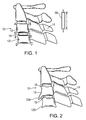
- a typical vertebrae 10 as illustrated in a somewhat idealized manner from the side in Fig. 1 , includes a body 12 that is tubular and somewhat rectangular shape when viewed from the side on a lateral X-ray image.. Ideally all the vertebrae are lined up so their individual channels form a passageway for the spinal cord (not shown). Extending rearwardly of the body 12, each vertebra 10 has a bony extension 14 known as the spinous processus (Latin singular: Processus Spinosus). Some of the vertebrae also have lateral extensions (Latin Singular: circumstances transversus) that are connected to the ribs forming a person's rib cage. However, these lateral extensions have been omitted for the sake of simplicity.
- the vertebrae are separated by a soft, somewhat gelatinous tissue known as the disc 16.
- the discs 16 are normally flexible to allow one vertebrae to flex or pivot with respect to the adjacent vertebrae and this action provides a person the ability to bend his body in different directions as required.
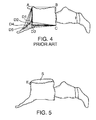
- a vertebral body can never look on a lateral X-ray image as a rectangle, but has a multi-angular shape, as illustrated in Figs. 2 and 3 , with spurs 12A, 12B, 12C or 12D.
- the top or bottom surface of a vertebra may also be visible as shown in Fig. 5 at S. That is why the determination of the exact position, size and shape of the vertebrae becomes a real challenge since determining these parameters using a pencil and ruler appears to be nearly impossible.
- the present invention resolves this problem by first idealizing all the vertebrae as a preselected regular geometric shape. As it will become apparent below, the actual shape is no longer that important as long as an appropriate idealized shape is selected consistently.
- a method for analyzing the spine has been previously suggested in which an image obtained of a vertebra is projected or depicted on a PC monitor, a preselected shape is designated and then an operator picks the corners of the preselected shape by hand. See the DX Analyzer by International Diagnostic Technologies, as described at www.dxanalyzer.com.
- DX Analyzer by International Diagnostic Technologies, as described at www.dxanalyzer.com.
- problems associated with this approach is that the system is utilizing a five point analysis for a square vertebral body and triangular vertebral body and if a single person reviews all the x-ray images, and, especially, if he does this exercise many times, he will develop some expertise so that he will pick the points fairly consistently.
- a person may pick the same positions for corners A, B and C and he may pick any one of the five positions D1, D2, D3, D4 or D5 as the fourth corner D. Or one person may pick D1, another person may pick D2, and so forth.
- the choice of all the corners is somewhat arbitrary, and there is a need for accuracy, the prior art method cannot be used consistently or with any kind of reliable repeatability.
- the DX Analyzer does not solve the distortion problems due to magnification and orientation.
- an operator is preselecting the source of X-rays and film distance, it does not specify the position of the patient in relation to the source of X-rays and the film. If the patient is standing closer to the X-ray source the image on the film will appear larger than normal, and if the patient is standing closer to the film, the image will appear closer to the normal size. Moreover, if he does not stand completely straight and/or not facing in a direction that is exactly perpendicular to the direction of the X-ray beam, the orientation (angular optical) distortion of an Xray image becomes an issue. Because of these flaws the accuracy of measurements is not attainable with the method used by the DX Analyzer.
- the present application provides a simplified and automated process for selecting the corners representing an idealized vertebrae body. Once the corners or vertices are established, size, shape, position and other information may then be determined with a high degree of accuracy, inter-examiner reliability and repeatability. The method is first demonstrated for two adjacent vertebrae, 10, 10' of Fig. 1 . Initially, an idealized shape is assigned for the subject vertebra, such as a parallelogram (As explained below, a parallelogram cannot be used to represent certain vertebra, in which case other idealized shapes are used).
- vertebrae generally have complex shapes and could be idealized using other shapes, however the present inventor has found that using a parallelogram, such as a square, a rectangle or a rhombus as an idealized shape is particularly advantageous in most instances.
- a rectangle has been chosen as the idealized shape for the vertebrae with the exceptions noted below.
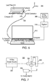
- Appparatus 300 includes a conventional X-ray beam source 302 selectively generating an X-ray beam along axis X-X toward a patient 304. The X-Rays penetrate the patient 304 and the exiting X-rays are captured by an X-ray sensor 306 or other similar means. Some of the dimensions in Fig. 7 are exaggerated for the sake of clarity.
- the X-ray image from the sensor 306 is provided to a control apparatus 308 which processes it and sends it either on the fly or on demand to a third party at a remote location.
- Attached to the region of patient's body, e.g., a section of the spine is a positioner 310.
- the purpose of the positioner is to provide both orientation and size (scale) information relevant to the X-ray images.
- the controller 308 may include a digitizer 310 that digitizes the image from the x-ray sensor 306, if necessary.
- the digitized image is received and stored by a microprocessor 312.
- the microprocessor 312 also receives orientation information indicative of the angular position of the patient 304 with respect to three axes X, Y and Z.
- the positioner 310 includes a digital compass 314, such as the one made by OceanServer Technologies Inc,. or other similar device. Imbedded or otherwise disposed within the housing of the positioner 310.
- the compass 314 is connected through a USB port 318 and a cable 320 to microprocessor 312.
- the positioner 310 has a T-shaped body made of a plastic material with the plate being disposed in the leg of the T as shown.
- a radiologist positions the patient 304 so that he is aligned along axis Y-Y perpendicularly to axis X-X.
- he places the positioned 316 in the vicinity of the vertebrae in question.
- the compass in the positioned provides readings indicative of the orientation of the patient and the radiologist may (optionally) use this information to check the position of the patient.
- the purpose of this invention is to automatically analyze the positions of the vertebrae in a section of the spine and then provide a proper prognosis. The process for accomplishing this is now described.
- the radiologist positions the patient as set forth above, applies the positioner to the patient's reference part of spine, positions the patient that the X-ray beam is at perpendicular to the lead plate embedded in the positioned according to the compass data shown on the screen of a computer, adjusts the source 302 so that the beam is collimated and takes the image.
- the X-ray image is sensed by sensor 306, digitized if necessary and provided to the controller 208.
- the controller adds other information, such as the orientation of each patient during each image, and other patient ID.
- a data file with all the images and related information is then transmitted to a remote location.
- the goal of the present invention is to quantify motion segments:
- the points defining a particular vertebra are not all selected manually. Instead, some points are selected manually, while the other points are selected automatically using the manually selected points and the preselected shape for the vertebral body. Additionally, the device guides the operator to follow the proper protocol for points placement and in the event if the points were placed in contrast to the protocol the shape of the drawn vertebra is drawn in particular to show the error was made.
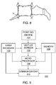
- This apparatus 101 includes an X-ray receiver, a display screen 102, a pointing device 104, a microprocessor 106, a memory 108 and a communication device 110.
- X-ray images of the spine of a patient are generated by the apparatus of Figs. 6 and 7 are received by an X-ray receiver 100.
- this X-ray image is a raw image such as the one shown in Fig. 5 with the top and side surfaces of the vertebrae being distorted due to the fact that the patient may not be oriented properly.
- the receiver sends raw image together with the angles indicating the angular distortions of the image to the microprocessor 106.
- the microprocessor reformates the image data to compensate for the distortions and includes the coefficient of distortion in quantification processes.
- the resulting image is then presented to an operator on screen 102 (step 203). This image is still somewhat raw and very irregular as shown in Fig. 8 .
- the pointing device 104 could be a mouse if the image is shown on a passive screen, or could be incorporated into the display screen 102, if an active, touch-sensitive screen is used.
- the inventor has analyzed close to 1100 vertebrae and came to several important conclusions.
- the first is that the upper side of the rectangle 12 (AB) and the posterior height (the length of segment BC) are the least subjected to any anatomical change (independently of whether the spine is healthy or it suffers from trauma, or other phenomenon)(See Fig 1 ).
- the operator preferably chooses the positions of points A, B and C ( Figs. 1 and 8 ) first.
- the points A,B, C, D are presented on the screen as shown, (In an alternate embodiment, the operator chooses point D as well, (and E, the 5 th , fifth point, which is not necessary) and the microprocessor chooses its own point and presents to the operator so that the operator can check his work, (quality control mechanism).
- the points for vertebrae 10 are stored into memory 108 and then the shape for the next vertebrae 10' are obtained and analyzed in a similar fashion to determine the positions of points A', B', C' D'. Once the second(if, necessary, third set of points) for second vertebra 10' were obtained, the shapes are compared to determine different characteristics, such as the vertical spacing between the vertebra, their relative angular positions, lateral offset, etc.
- the lateral offset two vertebra 12, 12' is equal to the lateral distance between lines AD and A'D'.
- the relative angular positions are represented between the orientations of any two respective lines, e.g, DC and D'C'.
- the vertical spacing is the distance between some of the respective points, e.g., points D and A' .
- Similar analysis is performed for vertebrae having an approximate triangular or linear shapes, as discussed below.
- the most complicated idealized shape described here is a rectangle, the technique can be readily extended to other idealized shapes having four, five, six sides, etc.
- the various individual vertebrae making up the various regions also have specific names or designations well known in the medical field.
- the X-ray image is presented on the display screen 102 (step 203) and each of the vertebrae is examined in sequence and classified as having one of the idealized shapes as described above by the operator.
- Cervical vertebrae are analyzed in step 204. For the occiput, only two points are required for a straight line selected by the operator.
- either three of four points are needed.
- the operator selects three points and the forth point is selected automatically (step 206) and for the rest of the vertebra (step 208) three points are selected and one point is automated, as discussed above.
- the idealized shape for the vertebrae is generated in step 212 and then saved in step 214 so that by the end of the process the characteristics of a particular region or a whole spine is known from the idealized shape and can be analyzed.
- two X-rays are taken: with the patient standing in two different positions, flexion and extension, and the respective X-rays are converted into respective image sets, the sets are processed in a fashion of idealized shapes, as discussed.
- each X-ray image is taken with the positioner in place which, as described above, has a perpendicular lead plate and the image of the plate 316 is visible .on an X-ray image as a reference, or target 50, as shown in Fig, 1 and oriented generally in a vertical direction between two points X and Y.
- the image of target 50 is provided as part of the data to the apparatus of fig.9 .
- Points X and Y can be detected as part of the process shown in Fig. 10 either manually or automatically for the microprocessor.
- the microprocessor can then use the distance L between these two points X and Y (and which is known a priori) to determine a proportional constant that can be used to determine the actual dimensions of the various vertebra shapes.
- the orientation of line XY representing reference target 50 can be used to determine the orientation of the various line segments in Fig. 1 with respect to the corresponding curvature of the back of the patient.
- the microprocessor geometrically quantifies the coefficient of distortion relative to the X-Y-Z orientation in connection with L between points X and Y and uses this coefficient further as an adjustment optical coefficient for reformatting quantification purposes.
- the various dimensions of the idealized shapes for the vertebra can be calibrated either during one of the intermediate steps, or in step 213 just before the data is saved in step 212.
- a motion segment consists of two adjacent vertebrae, including the intervertebral disk between them, and the ligaments that bind them together. Once measurements of relationship of one vertebra to another are obtained, they are compared to norms and abnormalities.
- biomechanical data is published by the AMA in the Guides to the Evaluation of Permanent Impairment Sixth Editi on and these are the guidelines that are then used to quantify the alteration of motion segment integrity and diagnose patients, mentioned above.
- the patient can be treated better, with better outcomes. For example, patients who have negative pathology and negative AOMSI will not receive treatment, and the insurers will save significant amount of money.
- the device is the choice for quantifications of motion segment integrity, as described above. It is an AOMSI (alteration of motion segment integrity) specific.
- the device is not using the 4 th point placed by the operator.
Landscapes
- Engineering & Computer Science (AREA)
- Health & Medical Sciences (AREA)
- Life Sciences & Earth Sciences (AREA)
- Medical Informatics (AREA)
- General Health & Medical Sciences (AREA)
- Nuclear Medicine, Radiotherapy & Molecular Imaging (AREA)
- Radiology & Medical Imaging (AREA)
- Physics & Mathematics (AREA)
- Computer Vision & Pattern Recognition (AREA)
- Optics & Photonics (AREA)
- Animal Behavior & Ethology (AREA)
- General Physics & Mathematics (AREA)
- Biophysics (AREA)
- High Energy & Nuclear Physics (AREA)
- Quality & Reliability (AREA)
- Pathology (AREA)
- Biomedical Technology (AREA)
- Heart & Thoracic Surgery (AREA)
- Molecular Biology (AREA)
- Surgery (AREA)
- Theoretical Computer Science (AREA)
- Public Health (AREA)
- Veterinary Medicine (AREA)
- Physiology (AREA)
- Orthopedic Medicine & Surgery (AREA)
- Dentistry (AREA)
- Oral & Maxillofacial Surgery (AREA)
- Apparatus For Radiation Diagnosis (AREA)
- Measurement Of The Respiration, Hearing Ability, Form, And Blood Characteristics Of Living Organisms (AREA)
- Measuring And Recording Apparatus For Diagnosis (AREA)
- Image Processing (AREA)
Applications Claiming Priority (3)
| Application Number | Priority Date | Filing Date | Title |
|---|---|---|---|
| US29011509P | 2009-12-24 | 2009-12-24 | |
| US12/881,411 US8571282B2 (en) | 2009-12-24 | 2010-09-14 | Method and apparatus for measuring spinal characteristics of a patient |
| PCT/US2010/057794 WO2011078933A1 (en) | 2009-12-24 | 2010-11-23 | Method and apparatus for measuring spinal characteristics of a patient |
Publications (3)
| Publication Number | Publication Date |
|---|---|
| EP2515781A1 EP2515781A1 (en) | 2012-10-31 |
| EP2515781A4 EP2515781A4 (en) | 2013-07-10 |
| EP2515781B1 true EP2515781B1 (en) | 2016-11-23 |
Family
ID=44186981
Family Applications (1)
| Application Number | Title | Priority Date | Filing Date |
|---|---|---|---|
| EP10839963.5A Not-in-force EP2515781B1 (en) | 2009-12-24 | 2010-11-23 | Method and apparatus for measuring spinal characteristics of a patient |
Country Status (9)
| Country | Link |
|---|---|
| US (1) | US8571282B2 (enExample) |
| EP (1) | EP2515781B1 (enExample) |
| JP (1) | JP5654042B2 (enExample) |
| KR (1) | KR101613337B1 (enExample) |
| CN (1) | CN102652004B (enExample) |
| AU (1) | AU2010333928B2 (enExample) |
| CA (1) | CA2782743C (enExample) |
| IL (1) | IL219894A (enExample) |
| WO (1) | WO2011078933A1 (enExample) |
Families Citing this family (11)
| Publication number | Priority date | Publication date | Assignee | Title |
|---|---|---|---|---|
| KR101748180B1 (ko) * | 2010-12-31 | 2017-06-16 | 주식회사 케이티 | 영상으로부터 피사체의 크기를 측정하기 위한 방법 및 장치 |
| US8848868B2 (en) * | 2011-08-24 | 2014-09-30 | Albert Davydov | X-ray system and method of using thereof |
| US8965083B2 (en) * | 2012-06-28 | 2015-02-24 | General Electric Company | Automatic detection of vertebrae boundaries in spine images |
| US9317926B2 (en) | 2013-03-06 | 2016-04-19 | Siemens Aktiengesellschaft | Automatic spinal canal segmentation using cascaded random walks |
| US9064307B2 (en) | 2013-06-28 | 2015-06-23 | General Electric Company | Methods and apparatus to generate three-dimensional spinal renderings |
| US10524723B2 (en) | 2014-07-23 | 2020-01-07 | Alphatec Spine, Inc. | Method for measuring the displacements of a vertebral column |
| US10792110B2 (en) | 2016-07-04 | 2020-10-06 | 7D Surgical Inc. | Systems and methods for determining intraoperative spinal orientation |
| CN112349392B (zh) * | 2020-11-25 | 2021-08-03 | 北京大学第三医院(北京大学第三临床医学院) | 一种人体颈椎医学图像处理系统 |
| CN112641452B (zh) * | 2020-12-09 | 2022-08-23 | 佛山市第一人民医院(中山大学附属佛山医院) | 一种颈椎治疗仪系统和控制方法,及其可读存储介质 |
| US12322133B2 (en) | 2022-03-29 | 2025-06-03 | Spinal Guides Labs Llc | Devices, systems and methods for precise human head positioning |
| US12011227B2 (en) | 2022-05-03 | 2024-06-18 | Proprio, Inc. | Methods and systems for determining alignment parameters of a surgical target, such as a spine |
Family Cites Families (26)
| Publication number | Priority date | Publication date | Assignee | Title |
|---|---|---|---|---|
| US9028A (en) * | 1852-06-15 | David kood | ||
| JP2693886B2 (ja) * | 1991-09-12 | 1997-12-24 | 株式会社 アデランス | X線写真撮影用指標片 |
| US5514180A (en) * | 1994-01-14 | 1996-05-07 | Heggeness; Michael H. | Prosthetic intervertebral devices |
| US6978166B2 (en) * | 1994-10-07 | 2005-12-20 | Saint Louis University | System for use in displaying images of a body part |
| AU3950595A (en) | 1994-10-07 | 1996-05-06 | St. Louis University | Surgical navigation systems including reference and localization frames |
| US6668083B1 (en) * | 1998-10-09 | 2003-12-23 | Koninklijke Philips Electronics N.V. | Deriving geometrical data of a structure from an image |
| JP2001095858A (ja) | 1999-03-25 | 2001-04-10 | Matsushita Seiko Co Ltd | 身体を動作させる装置 |
| US6468233B2 (en) * | 2000-06-26 | 2002-10-22 | Gerry Cook | Posture analyzer |
| US20030086596A1 (en) * | 2001-11-07 | 2003-05-08 | Medical Metrics, Inc. | Method, computer software, and system for tracking, stabilizing, and reporting motion between vertebrae |
| US8724865B2 (en) * | 2001-11-07 | 2014-05-13 | Medical Metrics, Inc. | Method, computer software, and system for tracking, stabilizing, and reporting motion between vertebrae |
| JP4070493B2 (ja) * | 2002-04-03 | 2008-04-02 | 株式会社東芝 | X線診断装置および医用画像解析装置 |
| JP4423197B2 (ja) * | 2002-08-25 | 2010-03-03 | ザ ユニヴァーシティ オブ ホンコン | 脊柱変形の矯正装置 |
| US7542791B2 (en) * | 2003-01-30 | 2009-06-02 | Medtronic Navigation, Inc. | Method and apparatus for preplanning a surgical procedure |
| EP1890261B1 (de) * | 2006-08-14 | 2009-02-18 | BrainLAB AG | Registrierung von MR-Daten anhand generischer Modelle |
| EP1598778B1 (en) * | 2004-05-18 | 2008-08-13 | Agfa HealthCare NV | Method for automatically mapping of geometric objects in digital medical images |
| US20060133694A1 (en) * | 2004-11-10 | 2006-06-22 | Agfa-Gevaert | Display device for displaying a blended image |
| US7309357B2 (en) * | 2004-12-30 | 2007-12-18 | Infinesse, Corporation | Prosthetic spinal discs |
| GB0503236D0 (en) * | 2005-02-16 | 2005-03-23 | Ccbr As | Vertebral fracture quantification |
| EP1868157A1 (en) * | 2006-06-14 | 2007-12-19 | BrainLAB AG | Shape reconstruction using X-ray images |
| US8041145B2 (en) * | 2006-11-17 | 2011-10-18 | The Invention Science Fund I, Llc | Distortion compensated imaging |
| US8187328B2 (en) * | 2007-01-08 | 2012-05-29 | Warsaw Orthopedic, Inc. | Expandable containment devices and methods |
| DE102007013407B4 (de) * | 2007-03-20 | 2014-12-04 | Siemens Aktiengesellschaft | Verfahren und Vorrichtung zur Bereitstellung einer Korrekturinformation |
| US8126249B2 (en) * | 2008-05-30 | 2012-02-28 | Optasia Medical Limited | Methods of and system for detection and tracking of osteoporosis |
| US8126234B1 (en) * | 2008-07-25 | 2012-02-28 | O.N.Diagnostics, LLC | Automated patient-specific bone-implant biomechanical analysis |
| EP2189942A3 (en) * | 2008-11-25 | 2010-12-15 | Algotec Systems Ltd. | Method and system for registering a medical image |
| CN101564323B (zh) * | 2009-04-20 | 2010-09-01 | 华中科技大学 | 基于乳腺x线摄片的乳腺病灶辅助诊断设备 |
-
2010
- 2010-09-14 US US12/881,411 patent/US8571282B2/en not_active Expired - Fee Related
- 2010-11-23 AU AU2010333928A patent/AU2010333928B2/en not_active Ceased
- 2010-11-23 JP JP2012545976A patent/JP5654042B2/ja not_active Expired - Fee Related
- 2010-11-23 KR KR1020127019505A patent/KR101613337B1/ko not_active Expired - Fee Related
- 2010-11-23 EP EP10839963.5A patent/EP2515781B1/en not_active Not-in-force
- 2010-11-23 CA CA2782743A patent/CA2782743C/en active Active
- 2010-11-23 CN CN201080056060.5A patent/CN102652004B/zh not_active Expired - Fee Related
- 2010-11-23 WO PCT/US2010/057794 patent/WO2011078933A1/en not_active Ceased
-
2012
- 2012-05-20 IL IL219894A patent/IL219894A/en active IP Right Grant
Also Published As
| Publication number | Publication date |
|---|---|
| EP2515781A4 (en) | 2013-07-10 |
| IL219894A0 (en) | 2012-07-31 |
| CN102652004B (zh) | 2015-07-15 |
| US20110157230A1 (en) | 2011-06-30 |
| CN102652004A (zh) | 2012-08-29 |
| JP2013515564A (ja) | 2013-05-09 |
| KR20120123370A (ko) | 2012-11-08 |
| IL219894A (en) | 2014-12-31 |
| KR101613337B1 (ko) | 2016-04-18 |
| WO2011078933A1 (en) | 2011-06-30 |
| CA2782743C (en) | 2017-01-24 |
| CA2782743A1 (en) | 2011-06-30 |
| US8571282B2 (en) | 2013-10-29 |
| EP2515781A1 (en) | 2012-10-31 |
| JP5654042B2 (ja) | 2015-01-14 |
| AU2010333928A1 (en) | 2012-06-07 |
| AU2010333928B2 (en) | 2013-09-26 |
Similar Documents
| Publication | Publication Date | Title |
|---|---|---|
| EP2515781B1 (en) | Method and apparatus for measuring spinal characteristics of a patient | |
| JP7116865B2 (ja) | 測定システム | |
| Lafage et al. | Validation of a new computer-assisted tool to measure spino-pelvic parameters | |
| EP3361958B1 (en) | Global spinal alignment planning method | |
| Korez et al. | A deep learning tool for fully automated measurements of sagittal spinopelvic balance from X-ray images: performance evaluation | |
| Chockalingam et al. | Computer-assisted Cobb measurement of scoliosis | |
| US20140303522A1 (en) | Scoliosis evaluation system and evaluation apparatus applied to the same system | |
| US20200155236A1 (en) | Systems and methods for customized spine guide using two-dimensional imaging | |
| US20090226055A1 (en) | Systems and methods for multi-dimensional characterization and classification of spinal shape | |
| Brown et al. | Computer-assisted location of reference points in three dimensions for radiographic cephalometry | |
| US20100174673A1 (en) | Method for reconstruction of a three-dimensional model of a body structure | |
| TWI282268B (en) | Medical image system and method for measuring vertebral axial rotation | |
| US20050119593A1 (en) | Method of viewing and controlling balance of the vertebral column | |
| Bagheri et al. | Reliability of three-dimensional spinal modeling of patients with idiopathic scoliosis using EOS system | |
| Troyanovich et al. | Chiropractic biophysics digitized radiographic mensuration analysis of the anteroposterior lumbopelvic view: a reliability study | |
| RU2392855C1 (ru) | Способ цифровой диагностики деформаций позвоночника | |
| KR20200073402A (ko) | 척추체 회전 측정 방법, 이를 수행하기 위한 장치 및 기록매체 | |
| KR101508178B1 (ko) | 척추 측만증 분석시스템 및 분석방법 | |
| WO2023285894A1 (en) | A method and system for verifying a correction of a spinal curvature by imaging and tracking | |
| Obeid et al. | Validation of an objective assessment instrument for non-surgical treatments of chest wall deformities | |
| US20250049476A1 (en) | Image-Based Implant Length Determination and Associated Systems, Devices, and Methods | |
| Penning et al. | Measurement of angular and linear segmental lumbar spine flexion-extension motion by means of image registration | |
| RU2454179C1 (ru) | Способ диагностики патологии позвоночника пациента с использованием индекса орла | |
| KR20170004514A (ko) | 척추 측만증 분석시스템 | |
| US20240173059A1 (en) | Device for helping to bend surgical rods |
Legal Events
| Date | Code | Title | Description |
|---|---|---|---|
| PUAI | Public reference made under article 153(3) epc to a published international application that has entered the european phase |
Free format text: ORIGINAL CODE: 0009012 |
|
| 17P | Request for examination filed |
Effective date: 20120724 |
|
| AK | Designated contracting states |
Kind code of ref document: A1 Designated state(s): AL AT BE BG CH CY CZ DE DK EE ES FI FR GB GR HR HU IE IS IT LI LT LU LV MC MK MT NL NO PL PT RO RS SE SI SK SM TR |
|
| DAX | Request for extension of the european patent (deleted) | ||
| A4 | Supplementary search report drawn up and despatched |
Effective date: 20130606 |
|
| RIC1 | Information provided on ipc code assigned before grant |
Ipc: G06T 7/00 20060101ALI20130531BHEP Ipc: A61B 19/00 20060101AFI20130531BHEP |
|
| REG | Reference to a national code |
Ref country code: DE Ref legal event code: R079 Ref document number: 602010038337 Country of ref document: DE Free format text: PREVIOUS MAIN CLASS: A61B0019000000 Ipc: A61B0090000000 |
|
| 17Q | First examination report despatched |
Effective date: 20160330 |
|
| GRAP | Despatch of communication of intention to grant a patent |
Free format text: ORIGINAL CODE: EPIDOSNIGR1 |
|
| RIC1 | Information provided on ipc code assigned before grant |
Ipc: G06T 7/00 20060101ALI20160414BHEP Ipc: A61B 90/00 20160101AFI20160414BHEP |
|
| INTG | Intention to grant announced |
Effective date: 20160511 |
|
| GRAS | Grant fee paid |
Free format text: ORIGINAL CODE: EPIDOSNIGR3 |
|
| GRAA | (expected) grant |
Free format text: ORIGINAL CODE: 0009210 |
|
| RAP1 | Party data changed (applicant data changed or rights of an application transferred) |
Owner name: IYOV INTELLECTUAL PROPERTIES CENTRALIS CAYMAN LIMI |
|
| RIN1 | Information on inventor provided before grant (corrected) |
Inventor name: IYOV INTELLECTUAL PROPERTIES CENTRALIS CAYMAN LIMI |
|
| RIN1 | Information on inventor provided before grant (corrected) |
Inventor name: DAVYDOV, ALBERT |
|
| AK | Designated contracting states |
Kind code of ref document: B1 Designated state(s): AL AT BE BG CH CY CZ DE DK EE ES FI FR GB GR HR HU IE IS IT LI LT LU LV MC MK MT NL NO PL PT RO RS SE SI SK SM TR |
|
| REG | Reference to a national code |
Ref country code: GB Ref legal event code: FG4D |
|
| REG | Reference to a national code |
Ref country code: FR Ref legal event code: PLFP Year of fee payment: 7 |
|
| REG | Reference to a national code |
Ref country code: CH Ref legal event code: EP |
|
| REG | Reference to a national code |
Ref country code: IE Ref legal event code: FG4D |
|
| REG | Reference to a national code |
Ref country code: AT Ref legal event code: REF Ref document number: 847151 Country of ref document: AT Kind code of ref document: T Effective date: 20161215 |
|
| REG | Reference to a national code |
Ref country code: DE Ref legal event code: R096 Ref document number: 602010038337 Country of ref document: DE |
|
| PG25 | Lapsed in a contracting state [announced via postgrant information from national office to epo] |
Ref country code: LV Free format text: LAPSE BECAUSE OF FAILURE TO SUBMIT A TRANSLATION OF THE DESCRIPTION OR TO PAY THE FEE WITHIN THE PRESCRIBED TIME-LIMIT Effective date: 20161123 |
|
| REG | Reference to a national code |
Ref country code: LT Ref legal event code: MG4D |
|
| REG | Reference to a national code |
Ref country code: NL Ref legal event code: MP Effective date: 20161123 |
|
| REG | Reference to a national code |
Ref country code: AT Ref legal event code: MK05 Ref document number: 847151 Country of ref document: AT Kind code of ref document: T Effective date: 20161123 |
|
| PG25 | Lapsed in a contracting state [announced via postgrant information from national office to epo] |
Ref country code: GR Free format text: LAPSE BECAUSE OF FAILURE TO SUBMIT A TRANSLATION OF THE DESCRIPTION OR TO PAY THE FEE WITHIN THE PRESCRIBED TIME-LIMIT Effective date: 20170224 Ref country code: SE Free format text: LAPSE BECAUSE OF FAILURE TO SUBMIT A TRANSLATION OF THE DESCRIPTION OR TO PAY THE FEE WITHIN THE PRESCRIBED TIME-LIMIT Effective date: 20161123 Ref country code: NL Free format text: LAPSE BECAUSE OF FAILURE TO SUBMIT A TRANSLATION OF THE DESCRIPTION OR TO PAY THE FEE WITHIN THE PRESCRIBED TIME-LIMIT Effective date: 20161123 Ref country code: LT Free format text: LAPSE BECAUSE OF FAILURE TO SUBMIT A TRANSLATION OF THE DESCRIPTION OR TO PAY THE FEE WITHIN THE PRESCRIBED TIME-LIMIT Effective date: 20161123 Ref country code: NO Free format text: LAPSE BECAUSE OF FAILURE TO SUBMIT A TRANSLATION OF THE DESCRIPTION OR TO PAY THE FEE WITHIN THE PRESCRIBED TIME-LIMIT Effective date: 20170223 |
|
| PG25 | Lapsed in a contracting state [announced via postgrant information from national office to epo] |
Ref country code: FI Free format text: LAPSE BECAUSE OF FAILURE TO SUBMIT A TRANSLATION OF THE DESCRIPTION OR TO PAY THE FEE WITHIN THE PRESCRIBED TIME-LIMIT Effective date: 20161123 Ref country code: PL Free format text: LAPSE BECAUSE OF FAILURE TO SUBMIT A TRANSLATION OF THE DESCRIPTION OR TO PAY THE FEE WITHIN THE PRESCRIBED TIME-LIMIT Effective date: 20161123 Ref country code: AT Free format text: LAPSE BECAUSE OF FAILURE TO SUBMIT A TRANSLATION OF THE DESCRIPTION OR TO PAY THE FEE WITHIN THE PRESCRIBED TIME-LIMIT Effective date: 20161123 Ref country code: ES Free format text: LAPSE BECAUSE OF FAILURE TO SUBMIT A TRANSLATION OF THE DESCRIPTION OR TO PAY THE FEE WITHIN THE PRESCRIBED TIME-LIMIT Effective date: 20161123 Ref country code: RS Free format text: LAPSE BECAUSE OF FAILURE TO SUBMIT A TRANSLATION OF THE DESCRIPTION OR TO PAY THE FEE WITHIN THE PRESCRIBED TIME-LIMIT Effective date: 20161123 Ref country code: PT Free format text: LAPSE BECAUSE OF FAILURE TO SUBMIT A TRANSLATION OF THE DESCRIPTION OR TO PAY THE FEE WITHIN THE PRESCRIBED TIME-LIMIT Effective date: 20170323 Ref country code: HR Free format text: LAPSE BECAUSE OF FAILURE TO SUBMIT A TRANSLATION OF THE DESCRIPTION OR TO PAY THE FEE WITHIN THE PRESCRIBED TIME-LIMIT Effective date: 20161123 Ref country code: BE Free format text: LAPSE BECAUSE OF NON-PAYMENT OF DUE FEES Effective date: 20161130 |
|
| REG | Reference to a national code |
Ref country code: CH Ref legal event code: PL |
|
| PG25 | Lapsed in a contracting state [announced via postgrant information from national office to epo] |
Ref country code: CZ Free format text: LAPSE BECAUSE OF FAILURE TO SUBMIT A TRANSLATION OF THE DESCRIPTION OR TO PAY THE FEE WITHIN THE PRESCRIBED TIME-LIMIT Effective date: 20161123 Ref country code: SK Free format text: LAPSE BECAUSE OF FAILURE TO SUBMIT A TRANSLATION OF THE DESCRIPTION OR TO PAY THE FEE WITHIN THE PRESCRIBED TIME-LIMIT Effective date: 20161123 Ref country code: LI Free format text: LAPSE BECAUSE OF NON-PAYMENT OF DUE FEES Effective date: 20161130 Ref country code: EE Free format text: LAPSE BECAUSE OF FAILURE TO SUBMIT A TRANSLATION OF THE DESCRIPTION OR TO PAY THE FEE WITHIN THE PRESCRIBED TIME-LIMIT Effective date: 20161123 Ref country code: CH Free format text: LAPSE BECAUSE OF NON-PAYMENT OF DUE FEES Effective date: 20161130 Ref country code: DK Free format text: LAPSE BECAUSE OF FAILURE TO SUBMIT A TRANSLATION OF THE DESCRIPTION OR TO PAY THE FEE WITHIN THE PRESCRIBED TIME-LIMIT Effective date: 20161123 Ref country code: RO Free format text: LAPSE BECAUSE OF FAILURE TO SUBMIT A TRANSLATION OF THE DESCRIPTION OR TO PAY THE FEE WITHIN THE PRESCRIBED TIME-LIMIT Effective date: 20161123 |
|
| REG | Reference to a national code |
Ref country code: IE Ref legal event code: MM4A |
|
| REG | Reference to a national code |
Ref country code: DE Ref legal event code: R097 Ref document number: 602010038337 Country of ref document: DE |
|
| PG25 | Lapsed in a contracting state [announced via postgrant information from national office to epo] |
Ref country code: BE Free format text: LAPSE BECAUSE OF FAILURE TO SUBMIT A TRANSLATION OF THE DESCRIPTION OR TO PAY THE FEE WITHIN THE PRESCRIBED TIME-LIMIT Effective date: 20161123 Ref country code: SM Free format text: LAPSE BECAUSE OF FAILURE TO SUBMIT A TRANSLATION OF THE DESCRIPTION OR TO PAY THE FEE WITHIN THE PRESCRIBED TIME-LIMIT Effective date: 20161123 Ref country code: BG Free format text: LAPSE BECAUSE OF FAILURE TO SUBMIT A TRANSLATION OF THE DESCRIPTION OR TO PAY THE FEE WITHIN THE PRESCRIBED TIME-LIMIT Effective date: 20170223 |
|
| PG25 | Lapsed in a contracting state [announced via postgrant information from national office to epo] |
Ref country code: MC Free format text: LAPSE BECAUSE OF FAILURE TO SUBMIT A TRANSLATION OF THE DESCRIPTION OR TO PAY THE FEE WITHIN THE PRESCRIBED TIME-LIMIT Effective date: 20161123 Ref country code: LU Free format text: LAPSE BECAUSE OF NON-PAYMENT OF DUE FEES Effective date: 20161130 |
|
| PLBE | No opposition filed within time limit |
Free format text: ORIGINAL CODE: 0009261 |
|
| STAA | Information on the status of an ep patent application or granted ep patent |
Free format text: STATUS: NO OPPOSITION FILED WITHIN TIME LIMIT |
|
| 26N | No opposition filed |
Effective date: 20170824 |
|
| REG | Reference to a national code |
Ref country code: FR Ref legal event code: PLFP Year of fee payment: 8 |
|
| PG25 | Lapsed in a contracting state [announced via postgrant information from national office to epo] |
Ref country code: IE Free format text: LAPSE BECAUSE OF NON-PAYMENT OF DUE FEES Effective date: 20161123 Ref country code: SI Free format text: LAPSE BECAUSE OF FAILURE TO SUBMIT A TRANSLATION OF THE DESCRIPTION OR TO PAY THE FEE WITHIN THE PRESCRIBED TIME-LIMIT Effective date: 20161123 |
|
| PG25 | Lapsed in a contracting state [announced via postgrant information from national office to epo] |
Ref country code: CY Free format text: LAPSE BECAUSE OF FAILURE TO SUBMIT A TRANSLATION OF THE DESCRIPTION OR TO PAY THE FEE WITHIN THE PRESCRIBED TIME-LIMIT Effective date: 20161123 Ref country code: HU Free format text: LAPSE BECAUSE OF FAILURE TO SUBMIT A TRANSLATION OF THE DESCRIPTION OR TO PAY THE FEE WITHIN THE PRESCRIBED TIME-LIMIT; INVALID AB INITIO Effective date: 20101123 |
|
| PG25 | Lapsed in a contracting state [announced via postgrant information from national office to epo] |
Ref country code: TR Free format text: LAPSE BECAUSE OF FAILURE TO SUBMIT A TRANSLATION OF THE DESCRIPTION OR TO PAY THE FEE WITHIN THE PRESCRIBED TIME-LIMIT Effective date: 20161123 Ref country code: MK Free format text: LAPSE BECAUSE OF FAILURE TO SUBMIT A TRANSLATION OF THE DESCRIPTION OR TO PAY THE FEE WITHIN THE PRESCRIBED TIME-LIMIT Effective date: 20161123 Ref country code: IS Free format text: LAPSE BECAUSE OF FAILURE TO SUBMIT A TRANSLATION OF THE DESCRIPTION OR TO PAY THE FEE WITHIN THE PRESCRIBED TIME-LIMIT Effective date: 20161123 |
|
| PG25 | Lapsed in a contracting state [announced via postgrant information from national office to epo] |
Ref country code: MT Free format text: LAPSE BECAUSE OF NON-PAYMENT OF DUE FEES Effective date: 20161123 |
|
| REG | Reference to a national code |
Ref country code: DE Ref legal event code: R082 Ref document number: 602010038337 Country of ref document: DE Representative=s name: MEISSNER BOLTE PATENTANWAELTE RECHTSANWAELTE P, DE Ref country code: DE Ref legal event code: R081 Ref document number: 602010038337 Country of ref document: DE Owner name: SPINAL GUIDES LABS, LLC, CAROLINA, US Free format text: FORMER OWNER: IYOV INTELLECTUAL PROPERTIES CENTRALIS CAYMAN LIMITED, GRAND CAYMAN, KY |
|
| REG | Reference to a national code |
Ref country code: GB Ref legal event code: 732E Free format text: REGISTERED BETWEEN 20191114 AND 20191120 |
|
| PG25 | Lapsed in a contracting state [announced via postgrant information from national office to epo] |
Ref country code: AL Free format text: LAPSE BECAUSE OF FAILURE TO SUBMIT A TRANSLATION OF THE DESCRIPTION OR TO PAY THE FEE WITHIN THE PRESCRIBED TIME-LIMIT Effective date: 20161123 |
|
| PGFP | Annual fee paid to national office [announced via postgrant information from national office to epo] |
Ref country code: FR Payment date: 20211126 Year of fee payment: 12 Ref country code: GB Payment date: 20211123 Year of fee payment: 12 Ref country code: DE Payment date: 20211129 Year of fee payment: 12 |
|
| PGFP | Annual fee paid to national office [announced via postgrant information from national office to epo] |
Ref country code: IT Payment date: 20211126 Year of fee payment: 12 |
|
| REG | Reference to a national code |
Ref country code: DE Ref legal event code: R119 Ref document number: 602010038337 Country of ref document: DE |
|
| GBPC | Gb: european patent ceased through non-payment of renewal fee |
Effective date: 20221123 |
|
| PG25 | Lapsed in a contracting state [announced via postgrant information from national office to epo] |
Ref country code: IT Free format text: LAPSE BECAUSE OF NON-PAYMENT OF DUE FEES Effective date: 20221123 Ref country code: GB Free format text: LAPSE BECAUSE OF NON-PAYMENT OF DUE FEES Effective date: 20221123 Ref country code: DE Free format text: LAPSE BECAUSE OF NON-PAYMENT OF DUE FEES Effective date: 20230601 |
|
| PG25 | Lapsed in a contracting state [announced via postgrant information from national office to epo] |
Ref country code: FR Free format text: LAPSE BECAUSE OF NON-PAYMENT OF DUE FEES Effective date: 20221130 |