EP2515556A2 - Reduktion von akustischen Rückkopplungen durch vibrationstechnische Verkürzung des Hörgeräts - Google Patents
Reduktion von akustischen Rückkopplungen durch vibrationstechnische Verkürzung des Hörgeräts Download PDFInfo
- Publication number
- EP2515556A2 EP2515556A2 EP12161537A EP12161537A EP2515556A2 EP 2515556 A2 EP2515556 A2 EP 2515556A2 EP 12161537 A EP12161537 A EP 12161537A EP 12161537 A EP12161537 A EP 12161537A EP 2515556 A2 EP2515556 A2 EP 2515556A2
- Authority
- EP
- European Patent Office
- Prior art keywords
- hearing aid
- housing part
- housing
- connection
- hook
- Prior art date
- Legal status (The legal status is an assumption and is not a legal conclusion. Google has not performed a legal analysis and makes no representation as to the accuracy of the status listed.)
- Granted
Links
Images


Classifications
-
- H—ELECTRICITY
- H04—ELECTRIC COMMUNICATION TECHNIQUE
- H04R—LOUDSPEAKERS, MICROPHONES, GRAMOPHONE PICK-UPS OR LIKE ACOUSTIC ELECTROMECHANICAL TRANSDUCERS; ELECTRIC HEARING AIDS; PUBLIC ADDRESS SYSTEMS
- H04R25/00—Electric hearing aids
- H04R25/45—Prevention of acoustic reaction, i.e. acoustic oscillatory feedback
- H04R25/456—Prevention of acoustic reaction, i.e. acoustic oscillatory feedback mechanically
Definitions
- the invention relates to a hearing aid.
- Hearing aids generate acoustic feedbacks (feedback), which are caused by various design features.
- Two key features that affect feedback are the weight and length of the hearing aid. Therefore, especially high performance hearing aids (so-called super power devices) with a high gain and heavy batteries tend to generate feedback in the acoustic range between 2 and 6 kHz. In almost all cases, therefore, sufficient amplification can not be achieved in directional microphone mode.
- Such hearing aids are usually designed as behind-the-ear hearing aids (BTE) and have a housing which is worn behind the ear by means of a hook. The housing encloses the speaker (earphone) and houses batteries for power supply.
- BTE behind-the-ear hearing aids
- the object of the invention is to provide a hearing aid which has reduced feedback. This object is achieved by the hearing aid according to claim 1.
- the invention relates to a hearing aid comprising a housing in which a receiver and a battery are arranged, wherein the housing has a first housing part and a second housing part, which are connected to one another via a connection, wherein at least one housing part or a damping element provided in the connection is formed of an elastic material.
- the damping element is preferably arranged between the first and the second housing part.
- the hearing aid may be a behind-the-ear hearing aid with a hook.
- the first housing part is formed from an elastic material.
- the battery is arranged in the first housing part.
- the receiver is arranged in the second housing part.
- the battery is arranged in the first housing part and the receiver in the second housing part.
- the second housing part is formed of a non-elastic material.
- non-elastic material is a thermoset plastic, in particular ABS.
- the elastic material be an elastomeric plastic, e.g. Silicone rubber, a thermoplastic elastomer (TPE) or a fluoroelastomer such as Viton® is.
- elastomeric plastic e.g. Silicone rubber, a thermoplastic elastomer (TPE) or a fluoroelastomer such as Viton® is.
- connection between the first and second housing part is a plug connection, screw connection or bayonet connection.
- the decoupling can be achieved by a damping element which is arranged between the first and second housing part, for example a ring or a disk of damping material, for example an elastomeric material.
- a housing part preferably the part which contains the battery, may be formed from a damping material, eg an elastomeric material.
- the other housing part can accommodate the microphone and the handset and from a rigid, non-elastic material, such as a thermoset material or a rigid thermoplastic material may be formed.
- the inventors have found that already a decoupling of the hook from the rest of the housing by a compound containing a damping element is an effective measure for the reduction of feedback.
- An even more effective damping is possible if the housing is divided into two housing parts, wherein in one housing part the battery and the other housing part of the listener is housed and wherein a housing part made of an elastic or soft damping material or a damping element between the two housing parts is arranged.
- the embodiment with a housing part made of an elastic or soft damping material has proved in experiments as the most effective measure for suppressing feedback.
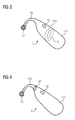
- FIG. 1 1 schematically shows a BTE hearing aid 1 according to the prior art, with a rigid housing 11, microphone opening 13, hook 15 and a connection 17 for a hearing tube (not shown), which leads into the ear.
- the housing 11 is integrally formed integrally with the hook 15.
- FIG. 2 schematically shows a first embodiment of a hearing aid 1 'according to the invention, with a first housing part 111 and second housing part 112.
- a battery (not shown) is arranged in the first housing part 111.
- the microphone behind a microphone opening 13 and the receiver (not shown) are arranged.
- the first housing part 111 is formed from an elastomeric plastic, for example TPE.
- the connection 19 is designed as a simple plug-in or latching connection.
- FIG. 3 schematically shows a second embodiment of a hearing aid 1 'according to the invention, with a first housing part 111 and second housing part 112.
- a battery (not shown) is arranged in the first housing part 111.
- the microphone 13 and the handset (not shown) are arranged in the second housing part 112, the microphone 13 and the handset (not shown) are arranged in the second housing part 112, the microphone 13 and the handset (not shown) are arranged.
- the first housing part 111 is formed of a Duroplastvasesstoff.
- the connection 19 ' is designed as a simple plug connection, wherein a damping element made of elastomeric material between the first housing part 111 and the second housing part 112 is arranged.
- FIG. 4 schematically shows a third embodiment of a hearing aid according to the invention, in which the hook 151 is connected via a damped connection 191 with the first housing part 111 '.
- a battery not shown
- the handset not shown
- FIG. 5 shows the hook 151 with connecting elements 193, 195, 197 according to the third embodiment FIG. 4 .
- the connection here comprises a damping element 193 made of a damping soft material, for example TPE, and first connecting element 195, which act together as a bayonet closure.
- first connecting element 195 which act together as a bayonet closure.
- second connection element 197 is arranged.
- FIG. 6 shows the hook 151 with connecting elements 193, 195, 197 according to the third embodiment FIG. 4 or 5 in a sectional view.
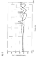
- FIG. 8 shows a diagram showing the feedback behavior of the hearing aid according to the invention according to the embodiment according to Figure 4-6 represents.
- This embodiment has a damping element between the hook and the rest of the housing.
- the dashed line shows the feedback behavior of a hearing aid according to the prior art with a one-piece, rigid housing. At approx. 4 kHz and 6 kHz, high maxima of the transfer function can be seen.
- the solid thin line shows the feedback behavior of the hearing aid according to the invention with a damping element between the hook and the rest of the housing, which is the embodiment according to FIGS. 4 to 6 equivalent. It can be seen that the sharply delimited maxima are no longer present at approx.
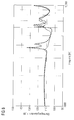
- this damping measure is surprisingly well suited to minimize feedback effectively if the same construction with a housing part made of an elastic or soft damping material is more effective (see. Fig. 7 where the feedback is completely suppressed at about 6-7 kHz).
Landscapes
- Health & Medical Sciences (AREA)
- General Health & Medical Sciences (AREA)
- Neurosurgery (AREA)
- Otolaryngology (AREA)
- Physics & Mathematics (AREA)
- Engineering & Computer Science (AREA)
- Acoustics & Sound (AREA)
- Signal Processing (AREA)
- Battery Mounting, Suspending (AREA)
- Telephone Set Structure (AREA)
- Diaphragms For Electromechanical Transducers (AREA)
Abstract
Description
- Die Erfindung betrifft ein Hörgerät.
- In Hörgeräten entstehen akustische Rückkopplungen (Feedback), welche durch verschiedene Konstruktionsmerkmale bedingt sind. Zwei Hauptmerkmale, welche Feedback beeinflussen, sind Gewicht und Länge des Hörgeräts. Daher neigen insbesondere leistungsstarke Hörgeräte (sog. Super Power Geräte) mit einer hohen Verstärkung und schweren Batterien dazu, Feedback im akustischen Bereich zwischen 2 und 6 kHz zu erzeugen. In fast allen Fällen kann daher im Richtmikrofonmodus keine ausreichende Verstärkung erreicht werden. Solche Hörgeräte sind üblicherweise als Hinter-dem-Ohr Hörgerät (HdO) ausgeführt und weisen ein Gehäuse auf, welches hinter dem Ohr mittels einer Aufhängung (Hook) getragen wird. Das Gehäuse umschließt den Lautsprecher (Hörer) und beherbergt Batterien zur Stromversorgung.
- Alle Versuche das Rückkopplungsproblem zu lösen, basieren darauf, das Mikrophon vom Gehäuse zu entkoppeln, in dem es aufgehängt ist, oder den Hörer so aufzuhängen, dass so viel Vibrationsenergie wie möglich durch die anwendungsspezifisch geformten Aufhängungen, die aus weichem Gummimaterial gebildet sind, aufgenommen werden (
US 20100208927 ). Diese Konzepte haben physikalische Grenzen und sind meist nicht genügend, um hohe Verstärkung im Richtmikrophonmodus zu erzielen. Bis jetzt gibt es nur eine bekannte Vorrichtung (Sumo von Oticon) mit einem äußerststabilen omnidirektionalen Modus, die aber kein Richtmikrophonmodus anbietet. Es gibt auch ein spezielles Hook Design (US 20080085024 A1 ), das die Vibrationen verringert. Diese Lösung ist ausreichend für kleinere und weniger leistungsfähige Vorrichtungen, aber stärkere Geräte benötigen andere Lösungen. - Aufgabe der Erfindung ist es, ein Hörgerät bereitzustellen, welches verringerte Rückkopplung aufweist. Diese Aufgabe wird durch das Hörgerät gemäß Anspruch 1 gelöst.
- Die Erfindung betrifft ein Hörgerät aufweisend ein Gehäuse, in welchem ein Hörer und eine Batterie angeordnet sind, wobei das Gehäuse ein erstes Gehäuseteil und ein zweites Gehäuseteil aufweist, die über eine Verbindung miteinander Verbunden sind, wobei mindestens ein Gehäuseteil oder ein bei der Verbindung vorgesehenes Dämpfungselement aus einem elastischen Material ausgebildet ist.
- Dies kann z.B. ein ringförmiges oder scheibenförmiges Dämpfungselement sein. Das Dämpfungselement ist vorzugsweise zwischen dem ersten und dem zweiten Gehäuseteil angeordnet.
- Bevorzugt kann das Hörgerät ein Hinter-dem-Ohr Hörgerät mit einem Hook sein.
- Es ist bevorzugt, dass der Hook das zweite Gehäuseteil bildet, welches über eine Verbindung mit dem ersten Gehäuseteil verbunden ist, und wobei bei der Verbindung ein Dämpfungselement angeordnet ist.
- Es ist bevorzugt, dass das erste Gehäuseteil aus einem elastischen Material ausgebildet ist.
- Es ist bevorzugt, dass die Batterie in dem ersten Gehäuseteil angeordnet ist.
- Es ist bevorzugt, dass der Hörer in dem zweiten Gehäuseteil angeordnet ist.
- Es ist besonders bevorzugt, dass die Batterie in dem ersten Gehäuseteil und der Hörer in dem zweiten Gehäuseteil angeordnet ist.
- Es ist bevorzugt, dass der zweite Gehäuseteil aus einem nicht-elastischen Material ausgebildet ist.
- Es ist ferner bevorzugt, dass das nicht-elastische Material ein Duroplastkunststoff, insbesondere ABS ist.
- Es ist bevorzugt, dass das elastische Material ein Elastomerkunststoff, z.B. Silikongummi, ein Thermoplast-Elastomer (TPE) oder ein Fluorelastomer wie Viton® ist.
- Es ist bevorzugt, dass die Verbindung zwischen dem ersten und zweiten Gehäuseteil eine Steckverbindung, Schraubverbindung oder Bajonettverbindung ist.
- Hohes Gewicht sowie die Länge des Gehäuses sind die Hauptfaktoren für starke Rückkopplung eines Hörgeräts. Dies gilt insbesondere für schwere, leistungsstarke Geräte.
- Besonders zwei Komponenten tragen zu einem hohen Gewicht bei schweren, leistungsstarken Geräten bei: Die Batterie und der Hörer. Ihr Gewicht kann nicht reduziert werden, ohne Leistungseinbußen hinzunehmen. Es ist jedoch möglich, diese beiden Komponenten in separaten, entkoppelten Gehäuseteilen unterzubringen. Dadurch erhält man ein Hörgerät mit zwei Teilen, die unabhängig von einander vibrieren und die Rückkopplungsfrequenzen werden in einen höheren Frequenzbereich verschoben (≥ 6kHz). Das ist sehr effektiv, da sowohl Länge als auch Gewicht durch die Trennung vibrationstechnisch reduziert werden. Die Entkopplung kann durch ein Dämpfungselement erreicht werden, dass zwischen dem ersten und zweiten Gehäuseteil angeordnet ist, z.B. ein Ring oder eine Scheibe aus dämpfenden Material, z.B. ein Elastomermaterial. Alternativ kann auch ein Gehäuseteil, bevorzugt der Teil, welcher die Batterie enthält, aus einem dämpfenden Material, z.B. ein Elastomermaterial, gebildet werden. Der andere Gehäuseteil kann das Mikrophon und den Hörer aufnehmen und aus einem starren, nicht-elastischen Material, z.B. ein Duroplastmaterial oder ein starres Thermoplastmaterial, gebildet sein.
- Überraschend haben die Erfinder gefunden, dass bereits eine Entkopplung des Hooks vom restlichen Gehäuse durch eine Verbindung, die ein Dämpfungselement enthält, eine effektive Maßnahme zur Reduktion von Rückkopplungen ist. Eine noch effektivere Dämpfung ist möglich, wenn das Gehäuse in zwei Gehäuseteile aufgeteilt ist, wobei in einem Gehäuseteil die Batterie und im anderen Gehäuseteil der Hörer untergebracht ist und wobei ein Gehäuseteil aus einem elastischen oder weichen dämpfenden Material gebildet ist oder ein Dämpfungselement zwischen den beiden Gehäuseteilen angeordnet ist. Die Ausführungsform mit einem Gehäuseteil aus einem elastischen oder weichen dämpfenden Material hat sich in Versuchen als die effektivste Maßnahme zur Unterdrückung von Rückkopplungen erwiesen.
- Im Folgenden wird die Erfindung beispielhaft beschrieben anhand der Figuren, welche zeigen:
- Figur 1
- ein Hörgerät gemäß dem Stand der Technik;
- Figur 2
- eine erste Ausführungsform eines erfindungsgemäßen Hörgeräts;
- Figur 3
- eine zweite Ausführungsform eines erfindungsgemäßen Hörgeräts;
- Figur 4
- eine dritte Ausführungsform eines erfindungsgemäßen Hörgeräts;
- Figur 5
- den Hook mit Verbindungselement gemäß der dritten Ausführungsform eines erfindungsgemäßen Hörgeräts in einer Explosionsansicht;
- Figur 6
- den Hook mit Verbindungselement gemäß der dritten Ausführungsform eines erfindungsgemäßen Hörgeräts in einer Schnittansicht;
- Figur 7
- ein Diagramm, welches das Rückkopplungsverhalten des erfindungsgemäßen Hörgeräts gemäß der Ausführungsform nach
Figur 2 darstellt; und - Figur 8
- ein Diagramm, welches das Rückkopplungsverhalten des erfindungsgemäßen Hörgeräts gemäß der Ausführungsform nach
Figur 4 darstellt -
Figur 1 zeigt schematisch ein HdO Hörgerät 1 gemäß dem Stand der Technik, mit einem starren Gehäuse 11, Mikrofonöffnung 13, Hook 15 und einem Anschluss 17 für einen Hörschlauch (nicht gezeigt), der in das Ohr führt. Das Gehäuse 11 ist einteilig und integral mit dem Hook 15 ausgebildet. -
Figur 2 zeigt schematisch eine erste Ausführungsform eines erfindungsgemäßen Hörgeräts 1', mit einem ersten Gehäuseteil 111 und zweiten Gehäuseteil 112. Im ersten Gehäuseteil 111 ist eine Batterie (nicht gezeigt) angeordnet. Im zweiten Gehäuseteil 112 sind das Mikrofon hinter einer Mikrofonöffnung 13 und der Hörer (nicht gezeigt) angeordnet. Der erste Gehäuseteil 111 ist aus einem Elastomerkunststoff gebildet, z.B. TPE. Die Verbindung 19 ist als einfache Steck- oder Rastverbindung ausgeführt. -
Figur 3 zeigt schematisch eine zweite Ausführungsform eines erfindungsgemäßen Hörgeräts 1', mit einem ersten Gehäuseteil 111 und zweiten Gehäuseteil 112. Im ersten Gehäuseteil 111 ist eine Batterie (nicht gezeigt) angeordnet. Im zweiten Gehäuseteil 112 sind das Mikrofon 13 und der Hörer (nicht gezeigt) angeordnet. Der erste Gehäuseteil 111 ist aus einem Duroplastkunststoff gebildet. Die Verbindung 19' ist als einfache Steckverbindung ausgeführt, wobei ein Dämpfungselement aus Elastomermaterial zwischen dem ersten Gehäuseteil 111 und dem zweiten Gehäuseteil 112 angeordnet ist. -
Figur 4 zeigt schematisch eine dritte Ausführungsform eines erfindungsgemäßen Hörgeräts, bei welchem der Hook 151 über eine bedämpfte Verbindung 191 mit dem ersten Gehäuseteil 111' verbunden ist. Im ersten Gehäuseteil 111' sind eine Batterie (nicht gezeigt) und der Hörer (nicht gezeigt) angeordnet. -
Figur 5 zeigt den Hook 151 mit Verbindungselementen 193, 195, 197 gemäß der dritten Ausführungsform ausFigur 4 . Die Verbindung umfasst hierbei ein Dämpfungselement 193 aus einem dämpfenden weichen Material, z.B. TPE, und erstes Verbindungselement 195, welche als Bajonettverschluss zusammen wirken. Dazwischen ist ein zweites Verbindungselement 197 angeordnet. Somit sind der Hook 151 und das restliche Gehäuse voneinander entkoppelt. -
Figur 6 zeigt den Hook 151 mit Verbindungselementen 193, 195, 197 gemäß der dritten Ausführungsform ausFigur 4 bzw. 5 in einer Schnittansicht. -
Figur 7 zeigt ein Diagramm, welches das Rückkopplungsverhalten des erfindungsgemäßen Hörgeräts darstellt gemäß der Ausführungsform nachFigur 2 darstellt. Diese Ausführungsform weist einen ersten Gehäuseteil aus elastischem und dämpfendem Material auf, der die Batterie des Hörgeräts umschließt. Die gestrichelte Linie zeigt das Rückkopplungsverhalten eines Hörgeräts mit einem einteiligen, starren Gehäuse gemäß dem Stand der Technik. Bei ca. 4 kHz und 6-7 kHz sind hohe Maxima der Übertragungsfunktion zu sehen, die auf Rückkopplungen in diesen Frequenzbereichen hinweisen (ideal wäre ein linearer Frequenzverlauf ohne Minima oder Maxima). Die durchgezogene dicke Linie zeigt das Rückkopplungsverhalten eines erfindungsgemäßen Hörgeräts mit einem ersten Gehäuseteil aus elastischem und dämpfendem Material. Die durchgezogene dünne Linie zeigt das Rückkopplungsverhalten eines erfindungsgemäßen Hörgeräts mit einem ersten Gehäuseteil aus elastischem und dämpfendem Material und einem Dämpfungselement zwischen Hook und dem restlichen Gehäuse, was einer Kombination der Merkmale der Ausführungsformen nachFigur 2 undFigur 4 entspricht. Bei beiden erfindungsgemäßen Hörgeräten ist zu erkennen, dass die scharf abgegrenzten Maxima bei ca. 4 kHz und 6-7 kHz nicht mehr vorhanden sind und der Frequenzverlauf insgesamt dem angestrebten idealen Frequenzverlauf viel näher kommt. -
Figur 8 zeigt ein Diagramm, welches das Rückkopplungsverhalten des erfindungsgemäßen Hörgeräts gemäß der Ausführungsform nachFigur 4-6 darstellt. Diese Ausführungsform weist ein Dämpfungselement zwischen Hook und dem restlichen Gehäuse auf. Die gestrichelte Linie zeigt das Rückkopplungsverhalten eines Hörgeräts gemäß dem Stand der Technik mit einem einteiligen, starren Gehäuse. Bei ca. 4 kHz und 6 kHz sind hohe Maxima der Übertragungsfunktion zu sehen. Die durchgezogene dünne Linie zeigt das Rückkopplungsverhalten des erfindungsgemäßen Hörgeräts mit einem Dämpfungselement zwischen Hook und dem restlichen Gehäuse, was der Ausführungsform nachFiguren 4 bis 6 entspricht. Es ist zu erkennen, dass die scharf abgegrenzten Maxima bei ca. 4 kHz und 6 kHz nicht mehr vorhanden sind und der Frequenzverlauf insgesamt dem angestrebten idealen Frequenzverlauf viel näher kommt. Auch diese Dämpfungsmaßnahme ist schon überraschend gut geeignet, Rückkopplungen effektiv zu minimieren, wenn gleich die Konstruktion mit einem Gehäuseteil aus einem elastischen oder weichen dämpfenden Material noch effektiver ist (vgl.Fig. 7 , wo die Rückkopplungen bei ca. 6-7 kHz vollständig unterdrückt sind).
Claims (11)
- Hörgerät (1), aufweisend ein Gehäuse, in welchem ein Hörer und eine Batterie angeordnet sind, wobei das Gehäuse ein erstes Gehäuseteil (111) und ein zweites Gehäuseteil (112, 151) aufweist, die über eine Verbindung (19, 191) miteinander Verbunden sind, wobei mindestens ein Gehäuseteil oder ein bei der Verbindung zwischen den Gehäuseteilen vorgesehenes Dämpfungselement (193) aus einem elastischen Material ausgebildet ist.
- Hörgerät (1) nach Anspruch 1, wobei das Hörgerät ein Hinter-dem-Ohr Hörgerät mit einem Hook (15, 151) ist.
- Hörgerät (1) nach Anspruch 2, wobei der Hook das zweite Gehäuseteil (151) ist, welches über die Verbindung (191) mit dem ersten Gehäuseteil (111ʹ) verbunden ist, und wobei bei der Verbindung(193, 195, 197) zwischen dem Hook und dem ersten Gehäuseteil ein Dämpfungselement (193) angeordnet ist.
- Hörgerät (1) nach Anspruch 1 oder 2, wobei das erste Gehäuseteil (111) aus einem elastischen Material ausgebildet ist.
- Hörgerät (1) nach einem der Ansprüche 1 bis 4, wobei die Batterie in dem ersten Gehäuseteil (111) angeordnet ist.
- Hörgerät (1) nach einem der Ansprüche 1 bis 5, wobei der Hörer in dem zweiten Gehäuseteil (112) angeordnet ist.
- Hörgerät (1) nach Anspruch 5 und 6, wobei die Batterie in dem ersten Gehäuseteil (111) und der Hörer in dem zweiten Gehäuseteil (112) angeordnet sind.
- Hörgerät (1) nach einem der Ansprüche 1 bis 7, wobei der zweite Gehäuseteil (112, 151) aus einem nicht-elastischen Material ausgebildet ist.
- Hörgerät (1) nach Anspruch 8, wobei das nicht-elastische Material ein Duroplastkunststoff, insbesondere ABS ist.
- Hörgerät (1) nach einem der Ansprüche 1 bis 9, wobei das elastische Material ein Elastomerkunststoff, insbesondere Silikongummi, TPE oder Viton ist.
- Hörgerät nach einem der Ansprüche 1 bis 10, wobei die Verbindung (19, 191) eine Steckverbindung, Schraubverbindung oder Bajonettverbindung ist.
Applications Claiming Priority (1)
| Application Number | Priority Date | Filing Date | Title |
|---|---|---|---|
| DE102011007848A DE102011007848A1 (de) | 2011-04-21 | 2011-04-21 | Reduktion von akustischen Rückkopplungen durch vibrationstechnische Verkürzung des Hörgeräts |
Publications (3)
| Publication Number | Publication Date |
|---|---|
| EP2515556A2 true EP2515556A2 (de) | 2012-10-24 |
| EP2515556A3 EP2515556A3 (de) | 2013-05-01 |
| EP2515556B1 EP2515556B1 (de) | 2016-07-20 |
Family
ID=46000729
Family Applications (1)
| Application Number | Title | Priority Date | Filing Date |
|---|---|---|---|
| EP12161537.1A Active EP2515556B1 (de) | 2011-04-21 | 2012-03-27 | Reduktion von akustischen Rückkopplungen durch vibrationstechnische Verkürzung des Hörgeräts |
Country Status (4)
| Country | Link |
|---|---|
| US (1) | US8855346B2 (de) |
| EP (1) | EP2515556B1 (de) |
| DE (1) | DE102011007848A1 (de) |
| DK (1) | DK2515556T3 (de) |
Families Citing this family (2)
| Publication number | Priority date | Publication date | Assignee | Title |
|---|---|---|---|---|
| JP5888879B2 (ja) * | 2011-06-02 | 2016-03-22 | 株式会社ミツバ | 駆動装置、及び停止位置検出方法 |
| WO2017167395A1 (en) * | 2016-04-01 | 2017-10-05 | Widex A/S | Receiver suspension for a hearing assisting device |
Citations (2)
| Publication number | Priority date | Publication date | Assignee | Title |
|---|---|---|---|---|
| US20080085024A1 (en) | 2005-05-25 | 2008-04-10 | Widex A/S | Hook for a hearing aid |
| US20100208927A1 (en) | 2009-02-17 | 2010-08-19 | Hartmut Ritter | Microphone module for a hearing device |
Family Cites Families (7)
| Publication number | Priority date | Publication date | Assignee | Title |
|---|---|---|---|---|
| DE19825998C2 (de) * | 1998-06-10 | 2003-01-30 | Siemens Audiologische Technik | Am Kopf tragbares Hörgerät |
| EP1120010B1 (de) * | 1998-10-07 | 2010-04-21 | Oticon A/S | Hinter-dem-ohr hörgerät |
| WO2003088710A1 (en) | 2002-04-18 | 2003-10-23 | Oticon A/S | Electric to acoustic transducer for a hearing aid |
| DE10248755B4 (de) * | 2002-10-18 | 2006-04-06 | Siemens Audiologische Technik Gmbh | Dämpfungsvorrichtung für Hörgerätegehäuse |
| CH699444B1 (de) * | 2006-10-11 | 2010-03-15 | Phonak Ag | Hörgerät. |
| DE102007023054A1 (de) | 2007-05-16 | 2008-11-27 | Siemens Medical Instruments Pte. Ltd. | Ohrpassstück mit Adapterdichtung |
| DE102007061310A1 (de) * | 2007-12-19 | 2009-06-25 | Siemens Medical Instruments Pte. Ltd. | Elektroakustischer Miniaturwandler mit Haltemittel zum Einbau in ein Hörgerät |
-
2011
- 2011-04-21 DE DE102011007848A patent/DE102011007848A1/de not_active Withdrawn
-
2012
- 2012-03-27 EP EP12161537.1A patent/EP2515556B1/de active Active
- 2012-03-27 DK DK12161537.1T patent/DK2515556T3/da active
- 2012-04-23 US US13/453,330 patent/US8855346B2/en active Active
Patent Citations (2)
| Publication number | Priority date | Publication date | Assignee | Title |
|---|---|---|---|---|
| US20080085024A1 (en) | 2005-05-25 | 2008-04-10 | Widex A/S | Hook for a hearing aid |
| US20100208927A1 (en) | 2009-02-17 | 2010-08-19 | Hartmut Ritter | Microphone module for a hearing device |
Also Published As
| Publication number | Publication date |
|---|---|
| EP2515556B1 (de) | 2016-07-20 |
| US8855346B2 (en) | 2014-10-07 |
| DK2515556T3 (da) | 2016-11-14 |
| DE102011007848A1 (de) | 2012-10-25 |
| EP2515556A3 (de) | 2013-05-01 |
| US20120269370A1 (en) | 2012-10-25 |
Similar Documents
| Publication | Publication Date | Title |
|---|---|---|
| DE102008052681B3 (de) | Ohrstück mit Stegen | |
| EP3491846B1 (de) | Hörhilfegerät und hörhilfevorrichtung | |
| EP3143778A1 (de) | Mems-schallwandler sowie schallwandleranordnung mit stopper-mechanismus | |
| EP2220873A2 (de) | Hörer | |
| DE102007023054A1 (de) | Ohrpassstück mit Adapterdichtung | |
| EP2219392B1 (de) | Microfonmodul für eine hörvorrichtung | |
| DE202013000547U1 (de) | Hörinstrumentgehäuse mit Steckverbindung | |
| EP3070964B1 (de) | Hörgerät, insbesondere hörhilfegerät | |
| EP2007172B1 (de) | Schallausgangsröhrchen mit 2-Komponenten-Aufbau | |
| EP1377119B1 (de) | Akustikmodul für ein Hörhilfsgerät | |
| DE102007023055A1 (de) | Ohrstück für eine Hörvorrichtung mit Bajonettverschluss | |
| DE102018214323A1 (de) | Hörinstrument mit einer Kopplungseinheit zur schwingungsgedämpften Lagerung eines Hörers | |
| EP2515556B1 (de) | Reduktion von akustischen Rückkopplungen durch vibrationstechnische Verkürzung des Hörgeräts | |
| EP2982135B1 (de) | Ohrkanal-hörer mit ohrpass-einheit | |
| DE102006043909B3 (de) | Hörer mit zusätzlicher Abschirmeinrichtung und Hörgerät mit diesem Hörer | |
| EP2557816A2 (de) | Montage einer Signalverarbeitungskomponente in einem Gehäuse einer Hörvorrichtung | |
| EP2073572A1 (de) | Elektroakustischer Miniaturwandler mit Haltemittel zum Einbau in ein Hörgerät | |
| DE102011080383A1 (de) | Hörer | |
| EP4106348A1 (de) | Hörvorrichtung | |
| EP2594089B1 (de) | Mikrofonschutzeinrichtung | |
| DE102018214322A1 (de) | Dämpfungseinrichtung für einen Hörer eines Hörinstruments sowie Hörinstrument mit einer solchen Dämpfungseinrichtung | |
| WO2021156357A1 (de) | Vorrichtung zur schallwandlung mit einem akustischen filter | |
| EP3355591B1 (de) | Hörgerät umfassend eine mikrofoneinheit mit einem gehäuse | |
| EP3419312B1 (de) | Hörgerät | |
| EP2897377A1 (de) | HdO-Hörinstrument mit Gehäuse und Schallschlauch |
Legal Events
| Date | Code | Title | Description |
|---|---|---|---|
| PUAI | Public reference made under article 153(3) epc to a published international application that has entered the european phase |
Free format text: ORIGINAL CODE: 0009012 |
|
| AK | Designated contracting states |
Kind code of ref document: A2 Designated state(s): AL AT BE BG CH CY CZ DE DK EE ES FI FR GB GR HR HU IE IS IT LI LT LU LV MC MK MT NL NO PL PT RO RS SE SI SK SM TR |
|
| AX | Request for extension of the european patent |
Extension state: BA ME |
|
| PUAL | Search report despatched |
Free format text: ORIGINAL CODE: 0009013 |
|
| AK | Designated contracting states |
Kind code of ref document: A3 Designated state(s): AL AT BE BG CH CY CZ DE DK EE ES FI FR GB GR HR HU IE IS IT LI LT LU LV MC MK MT NL NO PL PT RO RS SE SI SK SM TR |
|
| AX | Request for extension of the european patent |
Extension state: BA ME |
|
| RIC1 | Information provided on ipc code assigned before grant |
Ipc: H04R 25/00 20060101AFI20130325BHEP |
|
| 17P | Request for examination filed |
Effective date: 20140207 |
|
| RBV | Designated contracting states (corrected) |
Designated state(s): AL AT BE BG CH CY CZ DE DK EE ES FI FR GB GR HR HU IE IS IT LI LT LU LV MC MK MT NL NO PL PT RO RS SE SI SK SM TR |
|
| 17Q | First examination report despatched |
Effective date: 20141119 |
|
| RAP1 | Party data changed (applicant data changed or rights of an application transferred) |
Owner name: SIVANTOS PTE. LTD. |
|
| GRAP | Despatch of communication of intention to grant a patent |
Free format text: ORIGINAL CODE: EPIDOSNIGR1 |
|
| INTG | Intention to grant announced |
Effective date: 20160406 |
|
| RIN1 | Information on inventor provided before grant (corrected) |
Inventor name: SATTLER, MICHAEL Inventor name: BARTI, ENDRE, DR. Inventor name: RITTER, HARTMUT Inventor name: WEISTENHOEFER, CHRISTIAN, DR. |
|
| GRAS | Grant fee paid |
Free format text: ORIGINAL CODE: EPIDOSNIGR3 |
|
| GRAA | (expected) grant |
Free format text: ORIGINAL CODE: 0009210 |
|
| AK | Designated contracting states |
Kind code of ref document: B1 Designated state(s): AL AT BE BG CH CY CZ DE DK EE ES FI FR GB GR HR HU IE IS IT LI LT LU LV MC MK MT NL NO PL PT RO RS SE SI SK SM TR |
|
| REG | Reference to a national code |
Ref country code: GB Ref legal event code: FG4D Free format text: NOT ENGLISH |
|
| REG | Reference to a national code |
Ref country code: CH Ref legal event code: EP Ref country code: CH Ref legal event code: NV Representative=s name: E. BLUM AND CO. AG PATENT- UND MARKENANWAELTE , CH |
|
| REG | Reference to a national code |
Ref country code: IE Ref legal event code: FG4D Free format text: LANGUAGE OF EP DOCUMENT: GERMAN |
|
| REG | Reference to a national code |
Ref country code: AT Ref legal event code: REF Ref document number: 814920 Country of ref document: AT Kind code of ref document: T Effective date: 20160815 |
|
| REG | Reference to a national code |
Ref country code: DE Ref legal event code: R096 Ref document number: 502012007687 Country of ref document: DE |
|
| REG | Reference to a national code |
Ref country code: LT Ref legal event code: MG4D |
|
| REG | Reference to a national code |
Ref country code: DK Ref legal event code: T3 Effective date: 20161111 |
|
| REG | Reference to a national code |
Ref country code: NL Ref legal event code: MP Effective date: 20160720 |
|
| PG25 | Lapsed in a contracting state [announced via postgrant information from national office to epo] |
Ref country code: HR Free format text: LAPSE BECAUSE OF FAILURE TO SUBMIT A TRANSLATION OF THE DESCRIPTION OR TO PAY THE FEE WITHIN THE PRESCRIBED TIME-LIMIT Effective date: 20160720 Ref country code: LT Free format text: LAPSE BECAUSE OF FAILURE TO SUBMIT A TRANSLATION OF THE DESCRIPTION OR TO PAY THE FEE WITHIN THE PRESCRIBED TIME-LIMIT Effective date: 20160720 Ref country code: IS Free format text: LAPSE BECAUSE OF FAILURE TO SUBMIT A TRANSLATION OF THE DESCRIPTION OR TO PAY THE FEE WITHIN THE PRESCRIBED TIME-LIMIT Effective date: 20161120 Ref country code: NL Free format text: LAPSE BECAUSE OF FAILURE TO SUBMIT A TRANSLATION OF THE DESCRIPTION OR TO PAY THE FEE WITHIN THE PRESCRIBED TIME-LIMIT Effective date: 20160720 Ref country code: NO Free format text: LAPSE BECAUSE OF FAILURE TO SUBMIT A TRANSLATION OF THE DESCRIPTION OR TO PAY THE FEE WITHIN THE PRESCRIBED TIME-LIMIT Effective date: 20161020 Ref country code: IT Free format text: LAPSE BECAUSE OF FAILURE TO SUBMIT A TRANSLATION OF THE DESCRIPTION OR TO PAY THE FEE WITHIN THE PRESCRIBED TIME-LIMIT Effective date: 20160720 Ref country code: FI Free format text: LAPSE BECAUSE OF FAILURE TO SUBMIT A TRANSLATION OF THE DESCRIPTION OR TO PAY THE FEE WITHIN THE PRESCRIBED TIME-LIMIT Effective date: 20160720 Ref country code: RS Free format text: LAPSE BECAUSE OF FAILURE TO SUBMIT A TRANSLATION OF THE DESCRIPTION OR TO PAY THE FEE WITHIN THE PRESCRIBED TIME-LIMIT Effective date: 20160720 |
|
| PG25 | Lapsed in a contracting state [announced via postgrant information from national office to epo] |
Ref country code: SE Free format text: LAPSE BECAUSE OF FAILURE TO SUBMIT A TRANSLATION OF THE DESCRIPTION OR TO PAY THE FEE WITHIN THE PRESCRIBED TIME-LIMIT Effective date: 20160720 Ref country code: PT Free format text: LAPSE BECAUSE OF FAILURE TO SUBMIT A TRANSLATION OF THE DESCRIPTION OR TO PAY THE FEE WITHIN THE PRESCRIBED TIME-LIMIT Effective date: 20161121 Ref country code: LV Free format text: LAPSE BECAUSE OF FAILURE TO SUBMIT A TRANSLATION OF THE DESCRIPTION OR TO PAY THE FEE WITHIN THE PRESCRIBED TIME-LIMIT Effective date: 20160720 Ref country code: ES Free format text: LAPSE BECAUSE OF FAILURE TO SUBMIT A TRANSLATION OF THE DESCRIPTION OR TO PAY THE FEE WITHIN THE PRESCRIBED TIME-LIMIT Effective date: 20160720 Ref country code: GR Free format text: LAPSE BECAUSE OF FAILURE TO SUBMIT A TRANSLATION OF THE DESCRIPTION OR TO PAY THE FEE WITHIN THE PRESCRIBED TIME-LIMIT Effective date: 20161021 Ref country code: PL Free format text: LAPSE BECAUSE OF FAILURE TO SUBMIT A TRANSLATION OF THE DESCRIPTION OR TO PAY THE FEE WITHIN THE PRESCRIBED TIME-LIMIT Effective date: 20160720 |
|
| REG | Reference to a national code |
Ref country code: FR Ref legal event code: PLFP Year of fee payment: 6 |
|
| REG | Reference to a national code |
Ref country code: DE Ref legal event code: R097 Ref document number: 502012007687 Country of ref document: DE |
|
| PG25 | Lapsed in a contracting state [announced via postgrant information from national office to epo] |
Ref country code: EE Free format text: LAPSE BECAUSE OF FAILURE TO SUBMIT A TRANSLATION OF THE DESCRIPTION OR TO PAY THE FEE WITHIN THE PRESCRIBED TIME-LIMIT Effective date: 20160720 Ref country code: RO Free format text: LAPSE BECAUSE OF FAILURE TO SUBMIT A TRANSLATION OF THE DESCRIPTION OR TO PAY THE FEE WITHIN THE PRESCRIBED TIME-LIMIT Effective date: 20160720 |
|
| PLBE | No opposition filed within time limit |
Free format text: ORIGINAL CODE: 0009261 |
|
| STAA | Information on the status of an ep patent application or granted ep patent |
Free format text: STATUS: NO OPPOSITION FILED WITHIN TIME LIMIT |
|
| PG25 | Lapsed in a contracting state [announced via postgrant information from national office to epo] |
Ref country code: CZ Free format text: LAPSE BECAUSE OF FAILURE TO SUBMIT A TRANSLATION OF THE DESCRIPTION OR TO PAY THE FEE WITHIN THE PRESCRIBED TIME-LIMIT Effective date: 20160720 Ref country code: BG Free format text: LAPSE BECAUSE OF FAILURE TO SUBMIT A TRANSLATION OF THE DESCRIPTION OR TO PAY THE FEE WITHIN THE PRESCRIBED TIME-LIMIT Effective date: 20161020 Ref country code: SM Free format text: LAPSE BECAUSE OF FAILURE TO SUBMIT A TRANSLATION OF THE DESCRIPTION OR TO PAY THE FEE WITHIN THE PRESCRIBED TIME-LIMIT Effective date: 20160720 Ref country code: SK Free format text: LAPSE BECAUSE OF FAILURE TO SUBMIT A TRANSLATION OF THE DESCRIPTION OR TO PAY THE FEE WITHIN THE PRESCRIBED TIME-LIMIT Effective date: 20160720 |
|
| 26N | No opposition filed |
Effective date: 20170421 |
|
| PG25 | Lapsed in a contracting state [announced via postgrant information from national office to epo] |
Ref country code: SI Free format text: LAPSE BECAUSE OF FAILURE TO SUBMIT A TRANSLATION OF THE DESCRIPTION OR TO PAY THE FEE WITHIN THE PRESCRIBED TIME-LIMIT Effective date: 20160720 |
|
| PG25 | Lapsed in a contracting state [announced via postgrant information from national office to epo] |
Ref country code: MC Free format text: LAPSE BECAUSE OF FAILURE TO SUBMIT A TRANSLATION OF THE DESCRIPTION OR TO PAY THE FEE WITHIN THE PRESCRIBED TIME-LIMIT Effective date: 20160720 |
|
| REG | Reference to a national code |
Ref country code: IE Ref legal event code: MM4A |
|
| PG25 | Lapsed in a contracting state [announced via postgrant information from national office to epo] |
Ref country code: LU Free format text: LAPSE BECAUSE OF NON-PAYMENT OF DUE FEES Effective date: 20170327 |
|
| PG25 | Lapsed in a contracting state [announced via postgrant information from national office to epo] |
Ref country code: IE Free format text: LAPSE BECAUSE OF NON-PAYMENT OF DUE FEES Effective date: 20170327 |
|
| REG | Reference to a national code |
Ref country code: BE Ref legal event code: MM Effective date: 20170331 |
|
| REG | Reference to a national code |
Ref country code: FR Ref legal event code: PLFP Year of fee payment: 7 |
|
| REG | Reference to a national code |
Ref country code: AT Ref legal event code: MM01 Ref document number: 814920 Country of ref document: AT Kind code of ref document: T Effective date: 20170327 |
|
| PG25 | Lapsed in a contracting state [announced via postgrant information from national office to epo] |
Ref country code: BE Free format text: LAPSE BECAUSE OF NON-PAYMENT OF DUE FEES Effective date: 20170331 |
|
| PG25 | Lapsed in a contracting state [announced via postgrant information from national office to epo] |
Ref country code: AT Free format text: LAPSE BECAUSE OF NON-PAYMENT OF DUE FEES Effective date: 20170327 |
|
| PG25 | Lapsed in a contracting state [announced via postgrant information from national office to epo] |
Ref country code: MT Free format text: LAPSE BECAUSE OF FAILURE TO SUBMIT A TRANSLATION OF THE DESCRIPTION OR TO PAY THE FEE WITHIN THE PRESCRIBED TIME-LIMIT Effective date: 20160720 |
|
| PG25 | Lapsed in a contracting state [announced via postgrant information from national office to epo] |
Ref country code: AL Free format text: LAPSE BECAUSE OF FAILURE TO SUBMIT A TRANSLATION OF THE DESCRIPTION OR TO PAY THE FEE WITHIN THE PRESCRIBED TIME-LIMIT Effective date: 20160720 |
|
| PG25 | Lapsed in a contracting state [announced via postgrant information from national office to epo] |
Ref country code: HU Free format text: LAPSE BECAUSE OF FAILURE TO SUBMIT A TRANSLATION OF THE DESCRIPTION OR TO PAY THE FEE WITHIN THE PRESCRIBED TIME-LIMIT; INVALID AB INITIO Effective date: 20120327 |
|
| PG25 | Lapsed in a contracting state [announced via postgrant information from national office to epo] |
Ref country code: CY Free format text: LAPSE BECAUSE OF NON-PAYMENT OF DUE FEES Effective date: 20160720 |
|
| PG25 | Lapsed in a contracting state [announced via postgrant information from national office to epo] |
Ref country code: MK Free format text: LAPSE BECAUSE OF FAILURE TO SUBMIT A TRANSLATION OF THE DESCRIPTION OR TO PAY THE FEE WITHIN THE PRESCRIBED TIME-LIMIT Effective date: 20160720 |
|
| PG25 | Lapsed in a contracting state [announced via postgrant information from national office to epo] |
Ref country code: TR Free format text: LAPSE BECAUSE OF FAILURE TO SUBMIT A TRANSLATION OF THE DESCRIPTION OR TO PAY THE FEE WITHIN THE PRESCRIBED TIME-LIMIT Effective date: 20160720 |
|
| PGFP | Annual fee paid to national office [announced via postgrant information from national office to epo] |
Ref country code: DE Payment date: 20240321 Year of fee payment: 13 Ref country code: GB Payment date: 20240322 Year of fee payment: 13 |
|
| PGFP | Annual fee paid to national office [announced via postgrant information from national office to epo] |
Ref country code: FR Payment date: 20240319 Year of fee payment: 13 Ref country code: DK Payment date: 20240321 Year of fee payment: 13 |
|
| PGFP | Annual fee paid to national office [announced via postgrant information from national office to epo] |
Ref country code: CH Payment date: 20240401 Year of fee payment: 13 |
|
| REG | Reference to a national code |
Ref country code: DE Ref legal event code: R119 Ref document number: 502012007687 Country of ref document: DE |
|
| REG | Reference to a national code |
Ref country code: CH Ref legal event code: H13 Free format text: ST27 STATUS EVENT CODE: U-0-0-H10-H13 (AS PROVIDED BY THE NATIONAL OFFICE) Effective date: 20251023 |
|
| REG | Reference to a national code |
Ref country code: DK Ref legal event code: EBP Effective date: 20250331 |
|
| GBPC | Gb: european patent ceased through non-payment of renewal fee |
Effective date: 20250327 |
|
| PG25 | Lapsed in a contracting state [announced via postgrant information from national office to epo] |
Ref country code: DE Free format text: LAPSE BECAUSE OF NON-PAYMENT OF DUE FEES Effective date: 20251001 |
|
| PG25 | Lapsed in a contracting state [announced via postgrant information from national office to epo] |
Ref country code: GB Free format text: LAPSE BECAUSE OF NON-PAYMENT OF DUE FEES Effective date: 20250327 |
|
| PG25 | Lapsed in a contracting state [announced via postgrant information from national office to epo] |
Ref country code: FR Free format text: LAPSE BECAUSE OF NON-PAYMENT OF DUE FEES Effective date: 20250331 |
|
| PG25 | Lapsed in a contracting state [announced via postgrant information from national office to epo] |
Ref country code: CH Free format text: LAPSE BECAUSE OF NON-PAYMENT OF DUE FEES Effective date: 20250331 |
|
| PG25 | Lapsed in a contracting state [announced via postgrant information from national office to epo] |
Ref country code: DK Free format text: LAPSE BECAUSE OF NON-PAYMENT OF DUE FEES Effective date: 20250331 |