EP2515193B1 - Method for avoiding an unwanted collision between a tool and a workpiece with a machine tool - Google Patents
Method for avoiding an unwanted collision between a tool and a workpiece with a machine tool Download PDFInfo
- Publication number
- EP2515193B1 EP2515193B1 EP11162780.8A EP11162780A EP2515193B1 EP 2515193 B1 EP2515193 B1 EP 2515193B1 EP 11162780 A EP11162780 A EP 11162780A EP 2515193 B1 EP2515193 B1 EP 2515193B1
- Authority
- EP
- European Patent Office
- Prior art keywords
- tool
- workpiece
- model
- movement
- values
- Prior art date
- Legal status (The legal status is an assumption and is not a legal conclusion. Google has not performed a legal analysis and makes no representation as to the accuracy of the status listed.)
- Active
Links
Images

Classifications
-
- G—PHYSICS
- G05—CONTROLLING; REGULATING
- G05B—CONTROL OR REGULATING SYSTEMS IN GENERAL; FUNCTIONAL ELEMENTS OF SUCH SYSTEMS; MONITORING OR TESTING ARRANGEMENTS FOR SUCH SYSTEMS OR ELEMENTS
- G05B15/00—Systems controlled by a computer
- G05B15/02—Systems controlled by a computer electric
-
- G—PHYSICS
- G05—CONTROLLING; REGULATING
- G05B—CONTROL OR REGULATING SYSTEMS IN GENERAL; FUNCTIONAL ELEMENTS OF SUCH SYSTEMS; MONITORING OR TESTING ARRANGEMENTS FOR SUCH SYSTEMS OR ELEMENTS
- G05B19/00—Programme-control systems
- G05B19/02—Programme-control systems electric
- G05B19/18—Numerical control [NC], i.e. automatically operating machines, in particular machine tools, e.g. in a manufacturing environment, so as to execute positioning, movement or co-ordinated operations by means of programme data in numerical form
- G05B19/406—Numerical control [NC], i.e. automatically operating machines, in particular machine tools, e.g. in a manufacturing environment, so as to execute positioning, movement or co-ordinated operations by means of programme data in numerical form characterised by monitoring or safety
- G05B19/4061—Avoiding collision or forbidden zones
Definitions
- the invention relates to a method for avoiding an unwanted collision between a tool and a workpiece in a machine tool. Furthermore, the invention relates to a device for controlling a machine tool.
- a collision avoidance system in which a workpiece model is calculated by means of a simulation during the machining of the workpiece and a collision avoidance is realized based thereon computing time so that on the one hand a high computing power for performing such a collision avoidance system is required and on the other hand before the real machining of the workpiece can be started, the simulation must be run with a time advantage before the start of real workpiece machining, since the determination of the workpiece model in Despite the high computing power, the rule can not run at the same time as the actual machining of the workpiece.
- a method and a control for avoiding an unwanted collision between a tool and a workpiece in a machine tool are known in which a numerical control for a plurality of structural machine objects determines collision areas, wherein the collision areas are moved in dependence on machine coordinates and is checked for collision detection, whether the collision areas collide.
- the collision ranges are adapted in size as a function of the travel speed of individual axes of the machine tool and the computing time required for the collision detection.
- This object is achieved by a method for avoiding an unwanted collision between a tool and a workpiece in a machine tool, wherein when starting a processing of a part program, the determination of movement setpoints for controlling a relative movement between the tool and workpiece based on the part program and a determination of the material removal on Workpiece is started by the tool on the basis of the determined motion setpoints, wherein if after a completion or interruption of the execution of the parts program, the relative movement has come to a standstill, based on the determined material removal a workpiece model is determined, wherein the movement target values are determined based on a manual operation input, wherein Future movement target values to be expected on the basis of the desired movement values are determined, a brake end arrangement of the tool being determined on the basis of the expected future desired movement values, a tool model being determined on the basis of the brake end arrangement of the tool and a tool mold model describing the geometric shape of the tool, wherein it is checked whether the Tool model overlaps with the workpiece model, wherein in the case of a detected
- the invention does not require any safety distances between the tool and the workpiece, so that the method according to the invention can also be carried out in the case of very filigree and in particular small workpieces.
- the device for controlling a machine tool may be e.g. in the form of a CNC control, the CNC control e.g. may be in the form of a single or multiple arithmetic units, on which one or more computer programs are executed with program code for carrying out the method according to the invention.
- the arithmetic unit or arithmetic units can each have one or more processors on which the computer program or programs run.
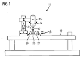
- FIG. 1 schematically a machine tool 11 is shown.
- the machine tool 11 has, in the exemplary embodiment, five machine axes, by means of which a relative movement between a tool 18, which in the exemplary embodiment is in the form of a milling cutter, and a workpiece 21 can be performed.
- the tool 18 is clamped in a tool holder 17, which is rotationally driven by a motor 15.
- the motor 15 and thus the tool 18 can be in for clarity FIG. 1 not shown drives in the X, Y and Z direction translational move and rotate in the direction ⁇ .
- the workpiece 21 can be rotated by means of a driven rotary table 25 in the direction ⁇ .
- the rotary table 25 is rotatably mounted on a stationary machine frame 19.
- the workpiece 21 is fixed by a clamping device 20 on the rotary table 25.
- the machine tool 11 thus has five machine axes, i. It is a so-called 5-axis machine tool.
- machine tool according to the invention may of course also have more or fewer than five machine axes.
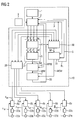
- FIG. 2 are in the form of a block diagram of an inventive device 10 for controlling a machine tool, that is shown in the context of the embodiment of the machine tool 11, and the drives for moving the tool and the workpiece.
- the device 10 has a control unit 2, which uses a part program 3 and / or a manual operation input to determine desired movement values x, y, z and ov for controlling a relative movement taking place between the tool 18 and the workpiece 21.
- the control unit 2 determines the movement target values on the basis of the part program 3, in which the movement to be performed by the tool with respect to the workpiece is defined in the form of commands.
- the movement of the tool and / or the workpiece can also be predetermined by an operator on site on the machine tool by means of a manual operation input, which is input via an operating device 1.
- the operating device 1 may be e.g. to act a handwheel and / or a keyboard.
- the part program 3 is usually generated by a CAM / CAD system and a possibly the CAM / CAD system connected downstream so-called post-processor.
- the movement of the tool 18 in relation to a stationary workpiece 21 is defined (see FIG. 3 ).
- the tool 18 is thereby moved along a movement path S.
- the desired movement values which are determined by the control unit 2, are within the scope of the exemplary embodiment in the form of position command values x, y and z, which are the movement of the tool center point TP of the tool 18 in the X, Y and Z directions. ie in 3-dimensional space, describe.
- the tool center point TP is a point preferably defined on the axis of rotation of the tool 18.
- orientation vector values ov are also determined by the control unit 2 as desired movement values, which indicate the orientation of the orientation vector OV of the tool and thus the orientation of the tool in 3-dimensional space when the tool 18 is moved on the movement path S.
- the position and orientation of the tool with respect to the workpiece on the movement path S for each point of the movement path S is defined.
- the determination of the movement setpoint values for controlling the relative movement taking place between the tool and the workpiece takes place on the basis of the part program at the start of the execution of the part program. Parallel to this, the determination of the material removal M on the workpiece is started on the basis of the determined motion setpoints.
- the desired movement values x, y, z and ov are transmitted immediately after their determination in the interpolation cycle (eg every 4 ms) to a material removal determination unit 30 which uses the movement reference values to determine the material removal M a from the machining of the workpiece by the tool Workpiece calculated.
- workpiece blank data R which describe the geometric shape of the blank (geometric shape of the workpiece before machining by the tool) of the workpiece and stored in a memory of the device 10 are further transmitted from the control unit 2 to the material removal determination unit 30. Furthermore, a tool shape model WFM describing the geometric shape of the tool, which is stored in a memory of the device 10, is also transmitted from the control unit 2 to the material removal determination unit 30. The material removal determination unit 30 then determines, based on the tool shape model WFM, the movement target values and the workpiece blank data R, by the machining of the tool on the workpiece resulting material removal M.
- the determination of the material removal M is carried out in the context of the embodiment, preferably in real time with the determination of the movement setpoints.
- the control unit 2 generates the desired movement values in the rule, preferably in a fixed time clock, the so-called interpolation clock. If, for example, motion setpoint values are generated by the control unit 2 every four milliseconds within the scope of the exemplary embodiment, then the material removal M is preferably recalculated and updated correspondingly every four milliseconds. Of course, the determination of the material removal M but also can not be done in real time.
- the workpiece model determination unit 31 uses the determined material removal M and the workpiece blank data R to determine a workpiece model WSM describing the geometric shape of the workpiece.
- the workpiece blank data R are transmitted from the control unit 2 to the workpiece model determination unit 31.
- An interruption of the execution of the part program may e.g. caused by the operator, e.g. by switching from automatic mode to manual mode.
- a grid is calculated, which connects to each other on the surface of the workpiece adjacent points, so that in the embodiment of the workpiece model WSM in the form of a so-called solid model, which through the grid is formed, is present.
- the determination of the workpiece model WSM on the basis of the material removal M and the workpiece blank data R is very computation-intensive, so that it is not processed in real time, ie. time parallel to the actual real processing on the machine can be performed.
- the control unit 2 transmits a start signal S to the workpiece model determination unit 31.
- the workpiece model determination unit 31 receives the start signal S, it determines the workpiece model WSM from the material removal M, which then no longer changes.
- the workpiece model determination unit 31 sends a blocking signal BL for a manual operation input to the control unit 2 until the workpiece model finishes the calculation is.
- the blocking signal BL As long as the blocking signal BL is present, manual operating inputs entered by an operator of the machine tool on the operating device 1, for controlling a relative movement between the tool and the workpiece, are blocked. Since the workpiece model determination unit 31 of the material removal M is finished as an input variable and the workpiece model WSM can be calculated relatively quickly on the basis of the material removal M from the workpiece model determination unit 31, the blocking of the manual operation input takes only a short time. The operator can then, ie after completed determination of the workpiece model WSM, by a manual operation input to the operating device 1 specify a relative movement between the tool and the workpiece, for example, to move the tool from the workpiece by means of machine axes. The control unit 2 determines based on the manual operation input, the movement target values x, y, z and ov in an analogous manner as previously controlled by the part program. The workpiece model WSM is transmitted to a checking unit 7.
- the movement target values are further supplied from the control unit 2 to a brake end determination unit 27 and within these to a first calculation unit 4 as input variables.
- the first calculation unit 4 of the brake end determination unit 27 determines from the current movement target values x, y, z and ov respectively expected future target movement values x ', y', z 'and ov'.
- the future movement values are determined by extrapolation from the motion setpoints currently generated by the control unit 2 and from the movement setpoints that are still in the past.
- the speed of the tool in each direction can be calculated from the current movement setpoints and the movement setpoints lying in the past, and based on this speed, an expected future position of the tool can be determined.
- the orientation of the orientation vector of the tool can also be extrapolated into the future.
- the movement setpoints are calculated in advance only by a so-called interpolation cycle of the control unit, ie usually only a few milliseconds into the future.
- the expected future movement target values thus agree very precisely with the actual future target movement values, which are generated by the control unit 2 in the next interpolation cycle.
- the expected future movement setpoints can also be further in the future than just a few milliseconds.
- the expected future movement setpoint values x ', y', z 'and ov' are then transmitted to a second calculation unit 5 of the brake end determination unit 27.
- the second calculation unit 5 uses the expected future movement setpoint values x ', y', z 'and ov' to determine a brake end arrangement BA of the tool 18.
- the brake end arrangement BA indicates the position and orientation of the tool when the relative movement between the tool and workpiece is at a standstill if a braking of the relative movement between the tool and the workpiece up to the standstill of the relative movement would be carried out on the basis of the expected future movement target values.
- the brake end arrangement BA is then transmitted to a tool model determination unit 6, which determines a tool model WM on the basis of the brake end arrangement BA and a tool shape model WMF describing the geometric shape of the tool.
- the tool model WM thus describes, in the context of the exemplary embodiment, the geometric shape of the tool, the position of the tool and the orientation of the tool.
- control unit 2 transmits the tool shape model WFM of the tool to the tool model determination unit 6.
- the tool shape model is stored in a memory of the device 10.
- the tool model WM is then transmitted to a checking unit 7, in which it is checked whether the tool model WM overlaps with the workpiece model WSM.
- the checking unit 7 determines that the tool model WM intersects with the workpiece model WSM, the checking unit 7 effects a braking of the relative movement between the tool and the workpiece until the relative movement stops. For this purpose, the checking unit 7 generates a brake signal BS in the event of an overlap of the tool model and the workpiece model and transmits this to the control unit 2, which causes a deceleration of the relative movement until the relative movement stops, via a corresponding generation of desired movement values.
- the motion command values are transmitted to a coordinate transformation unit 28, corresponding to the kinematics of the machine tool, ie the machine axes of the machine tool actually available for movement of the tool and / or the workpiece , Position command values x soll , y soll , z soll , ⁇ soll and ⁇ soll should be generated as control setpoints for controlling the movement of the drives to move the machine axes.
- the workpiece and / or the tool for realizing the relative movement between the workpiece and the tool is moved. For example, if the machine tool has a kinematics in which only the workpiece can be moved while the tool is stationary, the workpiece is moved to realize the relative movement between the workpiece and the tool.
- the position command values for the control of the drives are transmitted to the respective associated controller 8a, 8b, 8c, 8d and 8e, which drive correspondingly assigned converters 22a, 22b, 22c, 22d and 22e.
- the converters supply a respective associated electric motor 23a, 23b, 23c, 23d and 23e, each driving a machine axis.
- actual position values x is , y is , z is , ⁇ is and ⁇ is as Control values for controlling the drives to the regulations 8a, 8b, 8c, 8d and 8e transmitted.
- the method according to the invention for avoiding an unwanted collision thus operates in parallel with the movement of the tool and / or the workpiece actually carried out on the machine. It is thus no longer necessary after the start of processing the parts program, in which for a certain time a simulation is calculated in advance, before the actual real machining of the workpiece can be started. The processing time for machining the workpiece is thus reduced by the invention.
- the method preferably only determines expected movement target values over a relatively short period of time in the future, it works with high precision, so that no safety distances between workpiece and tool are necessary and thus the method is also used in the production of very small and especially filigree workpieces can.
- control unit 2 the brake assembly determination unit 27, the tool model determination unit 6, the verification unit 7, the material removal determination unit 30, the workpiece model determination unit 31, and the coordinate transformation unit 28 in the form of program code sections on one or several processors are running.
- the individual units can run on a single arithmetic unit, which may have a single or multiple processors or on several separate computing units run.
- the control unit 2, the brake assembly determination unit 27, the tool model determination unit 6, the verification unit 7, and the coordinate transformation unit 28 can run on a first computing unit and the material removal determination unit 30 and the workpiece model determination unit 31 run on a second computing unit, such as a personal computer.
- all units can also run on a single processor.
Description
Die Erfindung betrifft ein Verfahren zur Vermeidung einer ungewollten Kollision zwischen einem Werkzeug und einem Werkstück bei einer Werkzeugmaschine. Weiterhin betrifft die Erfindung eine Einrichtung zur Steuerung einer Werkzeugmaschine.The invention relates to a method for avoiding an unwanted collision between a tool and a workpiece in a machine tool. Furthermore, the invention relates to a device for controlling a machine tool.
Bei der Bearbeitung von Werkstücken mittels Werkzeugmaschinen müssen ungewollte Kollisionen zwischen dem Werkzeug und dem Werkstück, die zu einer Zerstörung des Werkzeugs und/oder des Werkstücks führen können, vermieden werden. Dabei kommt es, wenn die Abarbeitung eines Teileprogramm, das die Bewegungen der Werkzeugmaschine steuert, insbesondere mitten im Programm unterbrochen wird und das Werkzeug im Handbetrieb vom Werkstück wegbewegt wird und anschließend an die ursprüngliche Position im Handbetrieb zur Fortsetzung des Programms wieder hinbewegt wird, häufig zu ungewollten Kollisionen zwischen dem Werkzeug und dem Werkstück, da zur Realisierung der vom Bediener per Hand vorgegebenen Bewegung die Maschinenachsen im sogenannten Interpolationsverbund arbeiten und so mehrere Maschinenachsen zur Bewegung des Werkstücks und/oder des Werkzeugs gleichzeitig bewegt werden, so dass der Bediener oftmals schwer einschätzen kann, wie eine per Hand eingegebene Bewegungsvorgabe von der Werkzeugmaschine umgesetzt wird. Eine oft über mehrere Stunden oder gar Tage andauernde Bearbeitung auf der Werkzeugmaschine war dann umsonst, da das Werkstück nach der Kollision nicht mehr brauchbar ist.When machining workpieces by means of machine tools, unwanted collisions between the tool and the workpiece, which can lead to destruction of the tool and / or the workpiece, must be avoided. It happens when the execution of a part program that controls the movements of the machine tool, especially in the middle of the program is interrupted and the tool is moved away from the workpiece in manual mode and then moved back to the original position in manual mode to continue the program, often Unintentional collisions between the tool and the workpiece, since to implement the operator manually given movement, the machine axes work in the so-called interpolation and so several machine axes to move the workpiece and / or the tool are moved simultaneously, so that the operator can often difficult to estimate how a manually entered motion specification is implemented by the machine tool. An often lasting over several hours or even days processing on the machine tool was then in vain, since the workpiece after the collision is no longer useful.
Aus der Veröffentlichung "Gegen den Kollisionskurs", "Antriebspraxis 02/2007, ist ein Kollisionsvermeidungssystem bekannt, bei dem mittels einer Simulation während der Bearbeitung des Werkstücks ein Werkstückmodell berechnet wird und anhand diesem eine Kollisionsvermeidung realisiert wird. Die Berechnung eines Werkstückmodell benötigt aber sehr viel Rechenzeit, so dass zum einen eine hohe Rechenleistung zur Durchführung eines solchen Kollisionsvermeidungssystems benötigt wird und zum anderen bevor mit der realen Bearbeitung des Werkstücks begonnen werden kann, die Simulation mit einem zeitlichen Vorsprung vor dem Beginn der realen Werkstückbearbeitung ablaufen werden muss, da die Ermittelung des Werkstückmodells in der Regel trotz der hohen Rechenleistung nicht zeitgleich zur realen Bearbeitung des Werkstücks ablauffähig ist. In der Praxis führt dies dazu, dass wenn der Bediener den Startknopf zur Bearbeitung drückt, sich erst einmal an der Werkzeugmaschine nichts tut, da die Werkzeugmaschine zunächst über einen gewissen Zeitraum die bei der Bearbeitung des Werkstücks durch das Werkzeug entstehende aktuelle geometrische Werkstückform, d.h. das Werkstückmodell im Voraus berechnen muss. Hierdurch erhöht sich die Bearbeitungszeit für das Werkstück. Weiterhin werden insbesondere bei einer Bedienung per Hand relativ große Sicherheitsabstände zwischen Werkstück und Werkzeug benötigt.From the publication "Gegen die Kollisionskurs", "Antriebspraxis 02/2007, a collision avoidance system is known in which a workpiece model is calculated by means of a simulation during the machining of the workpiece and a collision avoidance is realized based thereon computing time so that on the one hand a high computing power for performing such a collision avoidance system is required and on the other hand before the real machining of the workpiece can be started, the simulation must be run with a time advantage before the start of real workpiece machining, since the determination of the workpiece model in Despite the high computing power, the rule can not run at the same time as the actual machining of the workpiece. In practice, this leads to the fact that when the operator presses the start button for processing, nothing first does on the machine tool, since the machine tool initially over a certain period of time resulting from the machining of the workpiece by the tool current geometric workpiece shape, ie Workpiece model must be calculated in advance. This increases the machining time for the workpiece. Furthermore, relatively large safety distances between the workpiece and the tool are required, especially when operated by hand.
Aus derFrom the
Aus derFrom the
Es ist Aufgabe der Erfindung, ein Verfahren zur Vermeidung einer ungewollten Kollision zwischen einem Werkzeug und einem Werkstück bei einer Werkzeugmaschine zu schaffen.It is an object of the invention to provide a method for avoiding an unwanted collision between a tool and a workpiece in a machine tool.
Diese Aufgabe wird gelöst durch ein Verfahren zur Vermeidung einer ungewollten Kollision zwischen einem Werkzeug und einem Werkstück bei einer Werkzeugmaschine, wobei bei Start einer Abarbeitung eines Teileprogramms die Ermittlung von Bewegungssollwerten zur Steuerung einer Relativbewegung zwischen Werkzeug und Werkstück anhand des Teileprogramms und eine Ermittlung des Materialabtrags am Werkstück durch das Werkzeug anhand der ermittelten Bewegungssollwerte gestartet wird, wobei wenn nach einer Beendigung oder Unterbrechung der Abarbeitung des Teileprogramms die Relativbewegung zum Stillstand gekommen ist, anhand des ermittelten Materialabtrags ein Werkstückmodell ermittelt wird, wobei anhand einer Handbedieneingabe die Bewegungssollwerte ermittelt werden, wobei anhand der Bewegungssollwerte zu erwartende zukünftige Bewegungssollwerte ermittelt werden, wobei anhand der zu erwartenden zukünftigen Bewegungssollwerte eine Bremsendanordnung des Werkzeugs ermittelt wird, wobei anhand der Bremsendanordnung des Werkzeugs und eines die geometrische Form des Werkzeugs beschreibenden Werkzeugformmodells ein Werkzeugmodell ermittelt wird, wobei überprüft wird, ob das Werkzeugmodell sich mit dem Werkstückmodell überschneidet, wobei im Falle einer festgestellten Überschneidung ein Abbremsen der Relativbewegung zwischen Werkzeug und Werkstück bis zum Stillstand der Relativbewegung bewirkt wird.This object is achieved by a method for avoiding an unwanted collision between a tool and a workpiece in a machine tool, wherein when starting a processing of a part program, the determination of movement setpoints for controlling a relative movement between the tool and workpiece based on the part program and a determination of the material removal on Workpiece is started by the tool on the basis of the determined motion setpoints, wherein if after a completion or interruption of the execution of the parts program, the relative movement has come to a standstill, based on the determined material removal a workpiece model is determined, wherein the movement target values are determined based on a manual operation input, wherein Future movement target values to be expected on the basis of the desired movement values are determined, a brake end arrangement of the tool being determined on the basis of the expected future desired movement values, a tool model being determined on the basis of the brake end arrangement of the tool and a tool mold model describing the geometric shape of the tool, wherein it is checked whether the Tool model overlaps with the workpiece model, wherein in the case of a detected overlap, a deceleration of the relative movement between the tool and the workpiece to the standstill of the relative movement is effected.
Weiterhin wird diese Aufgabe gelöst durch eine Einrichtung zur Steuerung einer Werkzeugmaschine, wobei die Einrichtung aufweist:
- eine Steuereinheit, die zur Ermittlung von Bewegungssollwerten zur Steuerung einer Relativbewegung zwischen Werkzeug und Werkstück anhand eines Teileprogramms und zum Starten der Ermittlung eines Materialabtrags am Werkstück durch das Werkzeug anhand der ermittelten Bewegungssollwerte bei Start der Abarbeitung des Teileprogramms ausgebildet ist, wobei die Steuereinheit weiterhin zur Ermittlung von Bewegungssollwerten zur Steuerung einer Relativbewegung zwischen Werkzeug und Werkstück anhand einer Handbedieneingabe ausgebildet ist,
- eine Materialabtragsermittlungseinheit, die zur Ermittlung des Materialabtrags am Werkstück durch das Werkzeug anhand der ermittelten Bewegungssollwerte ausgebildet ist,
- eine Werkstückmodellermittlungseinheit, die zur Ermittlung eines Werkstückmodells anhand des ermittelten Materialabtrags, wenn nach einer Beendigung oder Unterbrechung der Abarbeitung des Teileprogramms die Relativbewegung zum Stillstand gekommen ist, ausgebildet ist,
- eine Bremsendanordnungsermittlungseinheit, die zur Ermittlung von zu erwartenden zukünftigen Bewegungssollwerten anhand der Bewegungssollwerte ausgebildet ist, wobei die Bremsendanordnungsermittlungseinheit ausgebildet ist, anhand der zu erwartenden zukünftigen Bewegungssollwerte eine Bremsendanordnung des Werkzeugs zu ermitteln,
- eine Werkzeugmodellermittlungseinheit, die zur Ermittlung eines Werkzeugmodells anhand der Bremsendanordnung und einem die geometrische Form des Werkzeugs beschreibenden Werkzeugformmodells ausgebildet ist und
- eine Überprüfungseinheit, die zur Überprüfung, ob das Werkzeugmodell sich mit dem Werkstückmodell überschneidet, ausgebildet ist, wobei die Überprüfungseinheit ausgebildet ist, im Falle einer festgestellten Überschneidung eine Abbremsung der Relativbewegung zwischen Werkzeug und Werkstück bis zum Stillstand der Relativbewegung zu bewirken.
- a control unit which is designed to determine movement setpoint values for controlling a relative movement between the tool and the workpiece on the basis of a part program and to start the determination of a material removal on the workpiece by the tool on the basis of the determined movement setpoint values at the start of the execution of the part program, wherein the control unit continues to determine of motion setpoints for controlling a relative movement between tool and workpiece is formed by means of a manual operation input,
- a material removal determination unit, which is designed to determine the material removal on the workpiece by the tool on the basis of the determined movement setpoint values,
- a workpiece model determination unit which is designed to determine a workpiece model on the basis of the determined material removal, if the relative movement has come to a standstill after termination or interruption of the execution of the part program,
- a brake disposition determination unit that is configured to determine expected future movement target values based on the target movement values, wherein the brake end disposition determination unit is configured to determine the expected future movement setpoint values of a braking end arrangement of the tool,
- a tool model determination unit which is designed to determine a tool model based on the brake end assembly and a tool shape model describing the geometric shape of the tool and
- a checking unit which is designed to check whether the tool model intersects with the workpiece model, wherein the checking unit is designed to effect a deceleration of the relative movement between the tool and the workpiece until the relative movement stops, in the case of a detected overlap.
Die Erfindung benötigt keine Sicherheitsabstände zwischen Werkzeug und Werkstück, so dass das erfindungsgemäße Verfahren auch bei sehr filigranen, und insbesondere kleinen Werkstücken durchgeführt werden kann.The invention does not require any safety distances between the tool and the workpiece, so that the method according to the invention can also be carried out in the case of very filigree and in particular small workpieces.
Die Einrichtung zur Steuerung einer Werkzeugmaschine kann dabei z.B. in Form einer CNC-Steuerung vorliegen, wobei die CNC-Steuerung z.B. in Form einer einzelnen oder mehrerer Recheneinheiten vorliegen kann, auf der ein oder mehrere Computerprogramme mit Programmcode zur Durchführung des erfindungsgemäßen Verfahrens ausgeführt werden. Die Recheneinheit oder Recheneinheiten können dabei jeweils ein oder mehrere Prozessoren aufweisen, auf denen das oder die Computerprogramme ablaufen.The device for controlling a machine tool may be e.g. in the form of a CNC control, the CNC control e.g. may be in the form of a single or multiple arithmetic units, on which one or more computer programs are executed with program code for carrying out the method according to the invention. The arithmetic unit or arithmetic units can each have one or more processors on which the computer program or programs run.
Ein Ausführungsbeispiel der Erfindung ist in der Zeichnung dargestellt und wird im Folgenden näher erläutert. Darin zeigen:
- FIG 1
- eine Werkzeugmaschine,
- FIG 2
- eine erfindungsgemäße Einrichtung zur Steuerung ei-ner Werkzeugmaschine und
- FIG 3
- eine Bewegungsbahn S, entlang der ein Fräser zur Bearbeitung eines Werkstücks bewegt wird.
- FIG. 1
- a machine tool,
- FIG. 2
- a device according to the invention for controlling a machine tool and
- FIG. 3
- a movement path S, along which a milling cutter for machining a workpiece is moved.
In
Das Werkstück 21 ist durch eine Einspannvorrichtung 20 am Rundtisch 25 befestigt.The
Die Werkzeugmaschine 11 weist somit fünf Maschinenachsen auf, d.h. es handelt sich um eine sogenannte 5-achsige Werkzeugmaschine.The
Es sei dabei an dieser Stelle angemerkt, dass die erfindungsgemäße Werkzeugmaschine selbstverständlich auch noch mehr oder weniger als fünf Maschinenachsen aufweisen kann.It should be noted at this point that the machine tool according to the invention may of course also have more or fewer than five machine axes.
In
Die Einrichtung 10 weist eine Steuereinheit 2 auf, die anhand eines Teileprogramms 3 und/oder einer Handbedieneingabe Bewegungssollwerte x, y, z und ov zur Steuerung einer zwischen dem Werkzeug 18 und dem Werkstück 21 stattfindenden Relativbewegung, ermittelt. Die Steuereinheit 2 ermittelt die Bewegungssollwerte anhand des Teileprogramms 3, in dem die vom Werkzeug in Bezug zum Werkstück durchzuführende Bewegung in Form von Befehlen definiert ist. Zusätzlich kann die Bewegung des Werkzeugs und/oder des Werkstücks auch mittels einer Handbedieneingabe, welche über eine Bedieneinrichtung 1 eingegeben wird, von einem Bediener vor Ort an der Werkzeugmaschine vorgegeben werden. Bei der Bedieneinrichtung 1 kann es sich z.B. um ein Handrad und/oder eine Tastatur handeln.The
Das Teileprogramm 3 wird dabei üblicherweise von einem CAM/CAD-System und einem eventuell dem CAM/CAD-System nach geschalteten sogenannten Postprozessor erzeugt. Im Teileprogramm ist dabei die Bewegung des Werkzeugs 18 im Bezug zu einem ruhenden Werkstück 21 definiert (siehe
Durch die Bewegungssollwerte ist die Lage und Orientierung des Werkzeugs im Bezug zum Werkstück auf der Bewegungsbahn S für jeden Punkt der Bewegungsbahn S definiert.By the movement target values, the position and orientation of the tool with respect to the workpiece on the movement path S for each point of the movement path S is defined.
Die Ermittlung der Bewegungssollwerte zur Steuerung der zwischen Werkzeug und Werkstück stattfindenden Relativbewegung erfolgt anhand des Teileprogramms bei Start der Abarbeitung des Teileprogramms. Parallel hierzu wird die Ermittlung des Materialabtrags M am Werkstück anhand der ermittelten Bewegungssollwerte gestartet. Zur Ermittelung des Materialsabtrags M werden die Bewegungssollwerte x, y, z und ov unmittelbar nach deren Ermittlung im Interpolationstakt (z.B. alle 4 ms) an eine Materialabtragsermittlungseinheit 30 übermittelt, die anhand der Bewegungssollwerte den durch die Bearbeitung des Werkstücks durch das Werkzeug entstehende Materialabtrag M am Werkstück berechnet. Zur Ermittlung des Materialabtrags M werden weiterhin Werkstückrohteildaten R, die die geometrische Form des Rohteils (geometrische Form des Werkstücks vor der Bearbeitung durch das Werkzeug) des Werkstücks beschreiben und in einem Speicher der Einrichtung 10 hinterlegt sind von der Steuereinheit 2 an die Materialabtragsermittlungseinheit 30 übermittelt. Weiterhin wird auch ein die geometrische Form des Werkzeugs beschreibendes Werkzeugformmodell WFM, welches in einem Speicher der Einrichtung 10 gespeichert ist, von der Steuereinheit 2 an die Materialabtragsermittlungseinheit 30 übermittelt. Die Materialabtragsermittlungseinheit 30 ermittelt dann anhand des Werkzeugformmodells WFM, der Bewegungssollwerte sowie der Werkstückrohteildaten R durch die Bearbeitung des Werkzeugs am Werkstück entstehenden Materialabtrag M.The determination of the movement setpoint values for controlling the relative movement taking place between the tool and the workpiece takes place on the basis of the part program at the start of the execution of the part program. Parallel to this, the determination of the material removal M on the workpiece is started on the basis of the determined motion setpoints. In order to determine the material removal M, the desired movement values x, y, z and ov are transmitted immediately after their determination in the interpolation cycle (eg every 4 ms) to a material
Die Ermittlung des Materialabtrags M erfolgt im Rahmen des Ausführungsbeispiels vorzugsweise in Echtzeit mit der Ermittlung der Bewegungssollwerte. Die Steuereinheit 2 erzeugt dabei die Bewegungssollwerte in der Regel vorzugsweise in einem festen Zeittakt, dem sogenannten Interpolationstakt. Werden z.B. im Rahmen des Ausführungsbeispiels alle vier Millisekunden Bewegungssollwerte von der Steuereinheit 2 erzeugt, dann wird vorzugsweise entsprechend alle vier Millisekunden der Materialabtrag M neu berechnet und aktualisiert. Selbstverständlich kann die Ermittlung des Materialabtrags M aber auch nicht in Echtzeit erfolgen.The determination of the material removal M is carried out in the context of the embodiment, preferably in real time with the determination of the movement setpoints. The
Wenn nach einer Beendigung, d.h. nach einem vollständigen Durchlaufen des Teileprogamms, oder Unterbrechung der Abarbeitung des Teileprogramms 3 die Relativbewegung zwischen Werkstück und Werkzeug zum Stillstand gekommen ist, wird von der Werkstückmodellermittlungseinheit 31 anhand des ermittelten Materialabtrags M und der Werkstückrohteildaten R ein die geometrische Form des Werkstücks beschreibendes Werkstückmodell WSM ermittelt. Die Werkstückrohteildaten R werden von der Steuereinheit 2 an die Werkstückmodellermittlungseinheit 31 übermittelt. Eine Unterbrechung der Abarbeitung des Teileprogramms kann z.B. durch den Bediener veranlasst, z.B. durch eine Umschaltung von Automatikbetrieb auf Handbetrieb, erfolgen. Zur Ermittelung des Werkstückmodell WSM werden im Rahmen des Ausführungsbeispiels von der Werkstückmodellermittlungseinheit 31 ein Gitternetz berechnet, dass zueinander auf der Oberfläche des Werkstücks liegende benachbarte Punkte miteinander verbindet, so dass im Rahmen des Ausführungsbeispiels das Werkstückmodells WSM in Form eines sogenannten Volumenmodells, das durch das Gitternetz gebildet wird, vorliegt. Das Ermitteln des Werkstückmodells WSM anhand des Materialabtrags M und der Werkstückrohteildaten R ist sehr rechenaufwändig, so dass dieses nicht in Echtzeit, d.h. zeitlich parallel zur tatsächlich stattfindenden realen Bearbeitung an der Maschine durchgeführt werden kann.If after completion, i. after a complete passage through the parts program, or interrupting the execution of the part program 3, the relative movement between the workpiece and the tool has come to a standstill, the workpiece
Wenn nach einer Beendigung oder Unterbrechung der Abarbeitung des Teileprogramms 3 die Relativbewegung zwischen Werkstück und Werkzeug zum Stillstand gekommen ist, wird von der Steuereinheit 2 ein Startsignal S an die Werkstückmodellermittlungseinheit 31 übermittelt. Sobald die Werkstückmodellermittlungseinheit 31 das Startsignal S empfängt, ermittelt diese aus dem Materialabtrag M, der sich dann nicht mehr verändert, das Werkstückmodell WSM. Solange die Ermittelung des Werkstückmodells WSM durch die Werkstückmodellermittlungseinheit 31 läuft, sendet die Werkstückmodellermittlungseinheit 31 ein Blockiersignal BL für eine Handbedieneingabe an die Steuereinheit 2, bis das Werkstückmodell fertig berechnet ist. Solange das Blockierungssignal BL ansteht werden von einem Bediener der Werkzeugmaschine an der Bedieneinrichtung 1 eingegebene Handbedieneingaben, zur Steuerung einer Relativbewegung zwischen Werkzeug und Werkstück, blockiert. Da die Werkstückmodellermittlungseinheit 31 der Materialabtrag M als Eingangsgröße fertig vorliegt und anhand des Materialabtrag M von der Werkstückmodellermittlungseinheit 31 relativ schnell das Werkstückmodell WSM berechnet werden kann dauert die Blockierung der Handbedieneingabe nur eine kurze Zeit. Der Bediener kann anschließend, d.h. nach abgeschlossener Ermittelung des Werkstückmodell WSM, durch eine Handbedieneingabe an der Bedieneinrichtung 1 eine Relativbewegung zwischen Werkzeug und Werkstück vorgeben, um z.B. das Werkzeug aus dem Werkstück mittels der Maschinenachsen zu bewegen. Die Steuereinheit 2 ermittelt anhand der Handbedieneingabe die Bewegungssollwerte x, y, z und ov in analoger weise wie dies vorher durch das Teileprogramm gesteuert erfolgte. Das Werkstückmodell WSM wird an eine Überprüfungseinheit 7 übermittelt.If after a termination or interruption of the execution of the part program 3, the relative movement between the workpiece and the tool has come to a standstill, the
Die Bewegungssollwerte werden weiterhin von der Steuereinheit 2 an eine Bremsendanordungsermittlungseinheit 27 und innerhalb dieser an eine erste Berechnungseinheit 4 als Eingangsgrößen zugeführt. Die erste Berechnungseinheit 4 der Bremsendanordungsermittlungseinheit 27 ermittelt aus den aktuellen Bewegungssollwerten x, y, z und ov jeweils zu erwartende zukünftige Bewegungssollwerte x', y', z' und ov'. Die zukünftigen Bewegungswerte werden dabei im Rahmen des Ausführungsbeispiels durch Extrapolation aus den aktuell von der Steuereinheit 2 erzeugten Bewegungssollwerten und aus weiter in der Vergangenheit liegenden Bewegungssollwerten ermittelt. So kann z.B. aus den aktuellen Bewegungssollwerten und den in der Vergangenheit liegenden Bewegungssollwerten die Geschwindigkeit des Werkzeugs in jeder Richtung berechnet werden und anhand dieser Geschwindigkeit eine zu erwartende zukünftige Lage des Werkzeugs ermittelt werden. In analoger Weise kann auch die Orientierung des Orientierungsvektors des Werkzeugs in die Zukunft extrapoliert werden. Vorzugsweise werden dabei die Bewegungssollwerte nur um einen sogenannten Interpolationstakt der Steuereinheit, d.h. in der Regel nur um wenige Millisekunden in die Zukunft, voraus berechnet. Die zu erwartenden zukünftigen Bewegungssollwerte stimmen somit sehr genau mit den tatsächlichen zukünftigen Bewegungssollwerten überein, welche im nächsten Interpolationstakt von der Steuereinheit 2 erzeugt werden. Selbstverständlich können die zu erwartenden zukünftigen Bewegungssollwerte aber auch weiter in der Zukunft liegen als nur wenige Millisekunden.The movement target values are further supplied from the
Die zu erwartenden zukünftigen Bewegungssollwerte x', y', z' und ov' werden anschließend an eine zweite Berechnungseinheit 5 der Bremsendanordungsermittlungseinheit 27 übermittelt. Die zweite Berechnungseinheit 5 ermittelt anhand der zu erwartenden zukünftigen Bewegungssollwerte x', y', z' und ov' eine Bremsendanordnung BA des Werkzeugs 18. Die Bremsendanordnung BA gibt dabei die Lage und die Orientierung des Werkzeugs bei Stillstand der Relativbewegung zwischen Werkzeug und Werkstück an, wenn anhand den zu erwartenden zukünftigen Bewegungssollwerten eine Bremsung der Relativbewegung zwischen Werkzeug und Werkstück bis zum Stillstand der Relativbewegung durchgeführt werden würde. Die Bremsendanordnung BA wird anschließend an eine Werkzeugmodellermittelungseinheit 6 übermittelt, die anhand der Bremsendanordnung BA und ein die geometrische Form des Werkzeugs beschreibendes Werkzeugformmodell WMF ein Werkzeugmodell WM ermittelt. Das Werkzeugmodell WM beschreibt somit, im Rahmen des Ausführungsbeispiels, die geometrische Form des Werkzeugs, die Lage des Werkzeugs sowie die Orientierung des Werkzeugs.The expected future movement setpoint values x ', y', z 'and ov' are then transmitted to a second calculation unit 5 of the brake
Die Steuereinheit 2 übermittelt hierzu das Werkzeugformmodell WFM des Werkzeugs an die Werkzeugmodellermittelungseinheit 6. Das Werkzeugformmodell ist dabei in einem Speicher der Einrichtung 10 gespeichert. Das Werkzeugmodell WM wird anschließend an eine Überprüfungseinheit 7 übermittelt, in welcher geprüft wird, ob sich das Werkzeugmodell WM mit dem Werkstückmodell WSM überschneidet.For this purpose, the
Wenn die Überprüfungseinheit 7 feststellt, dass sich das Werkzeugmodell WM mit dem Werkstückmodell WSM überschneidet, wird von der Überprüfungseinheit 7 ein Abbremsen der Relativbewegung zwischen Werkzeug und Werkstück bis zum Stillstand der Relativbewegung bewirkt. Die Überprüfungseinheit 7 erzeugt hierzu im Falle einer Überschneidung von Werkzeugmodell und Werkstückmodell ein Bremssignal BS und übermittelt dieses an die Steuereinheit 2, die über eine entsprechende Erzeugung von Bewegungssollwerten eine Abbremsung der Relativbewegung bis zum Stillstand der Relativbewegung bewirkt.If the checking unit 7 determines that the tool model WM intersects with the workpiece model WSM, the checking unit 7 effects a braking of the relative movement between the tool and the workpiece until the relative movement stops. For this purpose, the checking unit 7 generates a brake signal BS in the event of an overlap of the tool model and the workpiece model and transmits this to the
Zeitlich gesehen parallel zu der Übermittlung der Bewegungssollwerte von der Steuereinheit 2 an die Bremsendanordungsermittlungseinheit 27 werden die Bewegungssollwerte an eine Koordinatentransformationseinheit 28 übermittelt, die entsprechend der Kinematik der Werkzeugmaschine, d.h. der tatsächlich zur Bewegung des Werkzeugs und/oder des Werkstücks zur Verfügung stehenden Maschinenachsen der Werkzeugmaschine, Lagesollwerte xsoll, ysoll, zsoll, αsoll und βsoll als Regelsollwerte zur Steuerung der Bewegung der Antriebe zur Bewegung der Maschinenachsen, erzeugt. Je nach dem, wie die Kinematik der Werkzeugmaschine ausgebildet ist, wird das Werkstück und/oder das Werkzeug zur Realisierung der Relativbewegung zwischen Werkstück und Werkzeug bewegt. So wird z.B. wenn die Werkzeugmaschine eine Kinematik aufweist, bei der nur das Werkstück bewegt werden kann, während das Werkzeug ruhend angeordnet ist, das Werkstück zur Realisierung der Relativbewegung zwischen Werkstück und Werkzeug bewegt.In time parallel to the transmission of the desired motor values from the
Die Lagesollwerte zur Steuerung der Antriebe werden an die jeweilige zugehörige Regelung 8a, 8b, 8c, 8d und 8e übermittelt, die entsprechend zugeordnete Stromrichter 22a, 22b, 22c, 22d und 22e ansteuern. Die Stromrichter versorgen einen jeweils zugeordneten Elektromotor 23a, 23b, 23c, 23d und 23e, die jeweils eine Maschinenachse antreiben. Dabei werden von Lagegebern, die der Übersichtlichkeit halber in
Das erfindungsgemäße Verfahren zur Vermeidung einer ungewollten Kollision arbeitet somit parallel zur tatsächlich an der Maschine durchgeführten Bewegung des Werkzeugs und/oder des Werkstücks. Es ist somit kein Zeitraum nach Start der Abarbeitung des Teileprogamms mehr notwendig, in dem für eine gewisse Zeit lang eine Simulation im Voraus berechnet wird, bevor mit der eigentlichen realen Bearbeitung des Werkstücks begonnen werden kann. Die Bearbeitungszeit zur Bearbeitung des Werkstücks wird somit durch die Erfindung reduziert.The method according to the invention for avoiding an unwanted collision thus operates in parallel with the movement of the tool and / or the workpiece actually carried out on the machine. It is thus no longer necessary after the start of processing the parts program, in which for a certain time a simulation is calculated in advance, before the actual real machining of the workpiece can be started. The processing time for machining the workpiece is thus reduced by the invention.
Da das Verfahren vorzugsweise nur über eine relativ kleine Zeitspanne in der Zukunft liegende zu erwartende Bewegungssollwerte ermittelt, arbeitet es hochgenau, so dass keine Sicherheitsabstände zwischen Werkstück und Werkzeug notwendig sind und somit das Verfahren auch bei der Fertigung von sehr kleinen und insbesondere filigranen Werkstücken eingesetzt werden kann.Since the method preferably only determines expected movement target values over a relatively short period of time in the future, it works with high precision, so that no safety distances between workpiece and tool are necessary and thus the method is also used in the production of very small and especially filigree workpieces can.
Es sei an dieser Stelle angemerkt, dass im Rahmen des Ausführungsbeispiels die Steuereinheit 2, die Bremsanordnungsermittlungseinheit 27, die Werkzeugmodellermittlungseinheit 6, die Überprüfungseinheit 7, die Materialabtragsermittlungseinheit 30, die Werkstückmodellermittlungseinheit 31, sowie die Koordinatentransformationseinheit 28 in Form von Programmcodeabschnitten vorliegen, die auf einem oder mehreren Prozessoren ausgeführt werden.It should be noted at this point that in the embodiment, the
Die einzelnen Einheiten können dabei auf einer einzelnen Recheneinheit, die über einen einzelnen oder mehrere Prozessoren verfügen kann oder aber auf mehreren voneinander getrennten Recheneinheiten, ablaufen. So kann z.B. die Steuereinheit 2, die Bremsanordnungsermittlungseinheit 27, die Werkzeugmodellermittlungseinheit 6, die Überprüfungseinheit 7 sowie die Koordinatentransformationseinheit 28 auf einer ersten Recheneinheit ablaufen und die Materialabtragsermittlungseinheit 30 und die Werkstückmodellermittlungseinheit 31 auf einer zweiten Recheneinheit, wie z.B. einem Personal Computer, ablaufen. Selbstverständlich können aber auch alle Einheiten auf einer einzigen Recheneinheit ablaufen.The individual units can run on a single arithmetic unit, which may have a single or multiple processors or on several separate computing units run. For example, the
Claims (4)
- Method for avoiding an unwanted collision between a tool (18) and a workpiece (21) in a machine tool (11), wherein when a part program (3) starts to run, the determination of setpoint movement values (x,y,z,ov) for controlling a relative movement between tool (18) and workpiece (21) is started based on the part program (3) and a determination of the material removal (M) at the workpiece (21) by the tool (18) is started based on the determined setpoint movement values (x,y,z,ov),
characterised in that if, after a termination or interruption of the running of the part program (3), the relative movement has stopped, a workpiece model (WSM) is determined based on the determined material removal (M), wherein the setpoint movement values (x,y,z,ov) are determined based on a manual operating input, wherein expected future setpoint movement values (x',y',z',ov') are determined based on the setpoint movement values (x,y,z,ov), wherein a braking end arrangement (BA) of the tool (18) is determined based on the expected future setpoint movement values (x',y',z',ov'), wherein a tool model (WM) is determined based on the braking end arrangement (BA) of the tool (18) and a tool form model (WFM) describing the geometric form of the tool (18), wherein it is checked whether the tool model (WM) overlaps with the workpiece model (WSM), wherein if an overlap is detected, a slowing down of the relative movement between tool (18) and workpiece (21) is brought about until the relative movement stops. - Computer program or computer programs with program code for performing a method according to claim 1, when the computer program or computer programs are executed by at least one computation unit.
- Facility for controlling a machine tool (11), wherein the facility has:- a control unit (2), which is configured to determine setpoint movement values (x,y,z,ov) for controlling a relative movement between tool (18) and workpiece (21) based on a part program (3) and to start the determination of a material removal (M) at the workpiece (21) by the tool (18) based on the determined setpoint movement values (x,y,z,ov) when the part program (3) starts to run, wherein the control unit (2) is also configured to determine setpoint movement values (x,y,z,ov) for controlling a relative movement between tool (18) and workpiece (21) based on a manual operating input,- a material removal determination unit (30), which is configured to determine material removal (M) at the workpiece (21) by the tool (18) based on the determined setpoint movement values (x,y,z,ov),- a workpiece model determination unit (31), which is configured to determine a workpiece model (WSM) based on the determined material removal (M), if, after a termination or interruption of the running of the part program (3), the relative movement has stopped,- a braking end arrangement determination unit (27), which is configured to determine expected future setpoint movement values (x',y',z',ov') based on the setpoint movement values (x,y,z, ov), wherein the braking end arrangement determination unit (27) is configured to determine a braking end arrangement (BA) of the tool (18) based on the expected future setpoint movement values (x',y',z',ov'),- a tool model determination unit, which is configured to determine a tool model (WM) based on the braking end arrangement (BA) and a tool form model (WFM) describing the geometric form of the tool (18) and- a check unit (7), which is configured to check whether the tool model (WM) overlaps with the workpiece model (WSM), wherein the check unit (7) is configured to bring about a slowing down of the relative movement between tool (18) and workpiece (21) until the relative movement stops, if an overlap is detected.
- Machine tool (11), wherein the machine tool (11) has a facility according to claim 3.
Priority Applications (4)
| Application Number | Priority Date | Filing Date | Title |
|---|---|---|---|
| EP11162780.8A EP2515193B1 (en) | 2011-04-18 | 2011-04-18 | Method for avoiding an unwanted collision between a tool and a workpiece with a machine tool |
| JP2012093041A JP5474122B2 (en) | 2011-04-18 | 2012-04-16 | How to avoid unintended collisions between tools and workpieces in machine tools |
| CN201210115500.0A CN102749886B (en) | 2011-04-18 | 2012-04-18 | Method for avoiding an unwanted collision between a tool and a workpiece in a machine tool |
| US13/449,838 US8630732B2 (en) | 2011-04-18 | 2012-04-18 | Method for avoiding an unwanted collision between a tool and a workpiece in a machine tool |
Applications Claiming Priority (1)
| Application Number | Priority Date | Filing Date | Title |
|---|---|---|---|
| EP11162780.8A EP2515193B1 (en) | 2011-04-18 | 2011-04-18 | Method for avoiding an unwanted collision between a tool and a workpiece with a machine tool |
Publications (2)
| Publication Number | Publication Date |
|---|---|
| EP2515193A1 EP2515193A1 (en) | 2012-10-24 |
| EP2515193B1 true EP2515193B1 (en) | 2014-04-02 |
Family
ID=44764321
Family Applications (1)
| Application Number | Title | Priority Date | Filing Date |
|---|---|---|---|
| EP11162780.8A Active EP2515193B1 (en) | 2011-04-18 | 2011-04-18 | Method for avoiding an unwanted collision between a tool and a workpiece with a machine tool |
Country Status (4)
| Country | Link |
|---|---|
| US (1) | US8630732B2 (en) |
| EP (1) | EP2515193B1 (en) |
| JP (1) | JP5474122B2 (en) |
| CN (1) | CN102749886B (en) |
Families Citing this family (8)
| Publication number | Priority date | Publication date | Assignee | Title |
|---|---|---|---|---|
| JP6175249B2 (en) * | 2013-02-26 | 2017-08-02 | 三菱重工工作機械株式会社 | Collision avoidance system for machine tools |
| EP2853354B1 (en) * | 2013-09-27 | 2018-05-16 | Siemens Aktiengesellschaft | Position control with collision avoidance, and adaptation of a machine model to the real machine |
| JP5845300B2 (en) * | 2014-03-07 | 2016-01-20 | ファナック株式会社 | A numerical controller that checks for incorrect axis commands. |
| US10549397B1 (en) * | 2017-12-19 | 2020-02-04 | Haas Automation, Inc. | Dynamic conveyor control system |
| TWI656942B (en) * | 2018-01-12 | 2019-04-21 | 財團法人工業技術研究院 | Machine tool collision avoidance method and system |
| EP3579066A1 (en) * | 2018-06-06 | 2019-12-11 | Agie Charmilles SA | Collision protection method |
| EP3690573B1 (en) * | 2019-01-30 | 2021-08-18 | Siemens Aktiengesellschaft | Control of a machine tool |
| TWI716849B (en) | 2019-04-10 | 2021-01-21 | 財團法人工業技術研究院 | Method and system for predicting collision detection of machining path |
Family Cites Families (19)
| Publication number | Priority date | Publication date | Assignee | Title |
|---|---|---|---|---|
| JPS6316303A (en) * | 1986-07-09 | 1988-01-23 | Mitsubishi Electric Corp | Numerical controller |
| JPH0659715A (en) * | 1991-03-09 | 1994-03-04 | Brother Ind Ltd | Numerical control method and device |
| JPH0639677A (en) * | 1992-07-24 | 1994-02-15 | Okuma Mach Works Ltd | Numerical control data generation device |
| US5835684A (en) * | 1994-11-09 | 1998-11-10 | Amada Company, Ltd. | Method for planning/controlling robot motion |
| JP3745526B2 (en) * | 1998-03-02 | 2006-02-15 | 日産自動車株式会社 | Roughing intermediate shape model generator for NC data creation |
| JP3180805B2 (en) * | 1999-07-16 | 2001-06-25 | 三菱電機株式会社 | Numerically controlled machine tools |
| DE19960834B4 (en) * | 1999-12-16 | 2006-10-26 | Agie S.A., Losone | Method and device for fault detection, in particular for collision detection, in the drive system of a numerically controlled machine tool |
| JP4812224B2 (en) * | 2000-06-30 | 2011-11-09 | 株式会社森精機製作所 | Machining simulation apparatus and method in NC machining |
| DE10114811A1 (en) * | 2001-03-26 | 2002-10-10 | Volkswagen Ag | System for producing multi-axis machining processes on workpieces, determines current path data and/or deviation while taking into account material removed by workpiece machining |
| JP2006163665A (en) * | 2004-12-06 | 2006-06-22 | Toshiba Corp | Numerical control information verification system for numerically controlled working machine and method |
| JP2007249671A (en) * | 2006-03-16 | 2007-09-27 | Nakamura Tome Precision Ind Co Ltd | Method for preventing collision in machine tool |
| WO2008025577A1 (en) * | 2006-05-30 | 2008-03-06 | Siemens Aktiengesellschaft | Method and device for monitoring a machine element to prevent its collision with an object in a machine tool, a production machine and/or a machine that is configured as a robot |
| JP4838647B2 (en) | 2006-07-05 | 2011-12-14 | 株式会社森精機製作所 | Machine tool controller |
| JP4298770B2 (en) * | 2007-08-28 | 2009-07-22 | ファナック株式会社 | Numerical control device with interference check function |
| DE102007045593A1 (en) * | 2007-09-14 | 2009-03-26 | Index-Werke Gmbh & Co. Kg Hahn & Tessky | Virtual machine tool for displaying actions of machining units of a real machine tool |
| JP5337636B2 (en) * | 2008-09-05 | 2013-11-06 | 株式会社森精機製作所 | Machining status monitoring method and machining status monitoring device |
| JP5139230B2 (en) * | 2008-10-06 | 2013-02-06 | オークマ株式会社 | Collision prevention device in numerical control device |
| JP5394093B2 (en) * | 2009-02-13 | 2014-01-22 | ファナック株式会社 | Numerical control device for controlling a machine tool having a tool breakage detection function |
| DE102009015934A1 (en) * | 2009-04-02 | 2010-10-07 | Dmg Electronics Gmbh | Method and device for generating control data for controlling a tool on a machine tool |
-
2011
- 2011-04-18 EP EP11162780.8A patent/EP2515193B1/en active Active
-
2012
- 2012-04-16 JP JP2012093041A patent/JP5474122B2/en active Active
- 2012-04-18 US US13/449,838 patent/US8630732B2/en active Active
- 2012-04-18 CN CN201210115500.0A patent/CN102749886B/en active Active
Also Published As
| Publication number | Publication date |
|---|---|
| US8630732B2 (en) | 2014-01-14 |
| CN102749886B (en) | 2014-10-22 |
| EP2515193A1 (en) | 2012-10-24 |
| CN102749886A (en) | 2012-10-24 |
| JP2012226749A (en) | 2012-11-15 |
| JP5474122B2 (en) | 2014-04-16 |
| US20130103180A1 (en) | 2013-04-25 |
Similar Documents
| Publication | Publication Date | Title |
|---|---|---|
| EP2515193B1 (en) | Method for avoiding an unwanted collision between a tool and a workpiece with a machine tool | |
| DE102008001011B4 (en) | Numerical control device | |
| DE112009005397B4 (en) | Numerical control device | |
| DE102017004366B4 (en) | Numerical control device | |
| DE102005037779B4 (en) | Numerical control unit | |
| DE102011108282B4 (en) | Numerical control for a multi-axis machine for machining a tilted working plane | |
| DE3806966C2 (en) | ||
| EP2008752A1 (en) | Machine for machining workpieces and method for machine processing of workpieces | |
| EP3056322B1 (en) | Method and system for operating a multi-axis machine, in particular a robot | |
| EP2650741B1 (en) | Machine tool | |
| EP0334044B1 (en) | Collision-preventing control system for two cutters | |
| DE102013015234A1 (en) | Method for controlling a gear cutting machine and gear cutting machine | |
| WO2002020213A2 (en) | Machine tool comprising collision verification | |
| DE102020124734A1 (en) | SIMULATION DEVICE | |
| WO2011110289A1 (en) | Method for determining an optimized desired curve profile in a multi-shaft machine for the on-the-fly processing of material to be conveyed | |
| EP2515192B1 (en) | Method for avoiding an unwanted collision between a tool and a workpiece with a machine tool | |
| DE102016014179B4 (en) | Numerical control | |
| EP3300521B1 (en) | Alignment method for workpieces | |
| EP0743579A2 (en) | Process for the operation of a numeric controlled machine tool or of a robot | |
| DE102015012147B4 (en) | Numerical control device | |
| DE102017222137A1 (en) | Numerical control device | |
| DE102017011602A1 (en) | Numerical control | |
| EP3689555A1 (en) | Force-limited method of at least one element of a production machine in manual operation | |
| WO2018033404A1 (en) | Creation of optimized path data for a machine tool | |
| EP3792716B1 (en) | Numerical control with buffering of load setpoints |
Legal Events
| Date | Code | Title | Description |
|---|---|---|---|
| PUAI | Public reference made under article 153(3) epc to a published international application that has entered the european phase |
Free format text: ORIGINAL CODE: 0009012 |
|
| AK | Designated contracting states |
Kind code of ref document: A1 Designated state(s): AL AT BE BG CH CY CZ DE DK EE ES FI FR GB GR HR HU IE IS IT LI LT LU LV MC MK MT NL NO PL PT RO RS SE SI SK SM TR |
|
| AX | Request for extension of the european patent |
Extension state: BA ME |
|
| RAP1 | Party data changed (applicant data changed or rights of an application transferred) |
Owner name: SIEMENS AKTIENGESELLSCHAFT |
|
| 17P | Request for examination filed |
Effective date: 20130424 |
|
| GRAP | Despatch of communication of intention to grant a patent |
Free format text: ORIGINAL CODE: EPIDOSNIGR1 |
|
| RIC1 | Information provided on ipc code assigned before grant |
Ipc: G05B 19/4061 20060101AFI20131015BHEP Ipc: G05B 15/02 20060101ALI20131015BHEP |
|
| INTG | Intention to grant announced |
Effective date: 20131031 |
|
| GRAS | Grant fee paid |
Free format text: ORIGINAL CODE: EPIDOSNIGR3 |
|
| GRAA | (expected) grant |
Free format text: ORIGINAL CODE: 0009210 |
|
| AK | Designated contracting states |
Kind code of ref document: B1 Designated state(s): AL AT BE BG CH CY CZ DE DK EE ES FI FR GB GR HR HU IE IS IT LI LT LU LV MC MK MT NL NO PL PT RO RS SE SI SK SM TR |
|
| REG | Reference to a national code |
Ref country code: GB Ref legal event code: FG4D Free format text: NOT ENGLISH |
|
| REG | Reference to a national code |
Ref country code: CH Ref legal event code: EP Ref country code: AT Ref legal event code: REF Ref document number: 660474 Country of ref document: AT Kind code of ref document: T Effective date: 20140415 |
|
| REG | Reference to a national code |
Ref country code: IE Ref legal event code: FG4D Free format text: LANGUAGE OF EP DOCUMENT: GERMAN |
|
| REG | Reference to a national code |
Ref country code: DE Ref legal event code: R096 Ref document number: 502011002575 Country of ref document: DE Effective date: 20140515 |
|
| REG | Reference to a national code |
Ref country code: NL Ref legal event code: VDEP Effective date: 20140402 |
|
| REG | Reference to a national code |
Ref country code: LT Ref legal event code: MG4D |
|
| PG25 | Lapsed in a contracting state [announced via postgrant information from national office to epo] |
Ref country code: NL Free format text: LAPSE BECAUSE OF FAILURE TO SUBMIT A TRANSLATION OF THE DESCRIPTION OR TO PAY THE FEE WITHIN THE PRESCRIBED TIME-LIMIT Effective date: 20140402 Ref country code: CZ Free format text: LAPSE BECAUSE OF FAILURE TO SUBMIT A TRANSLATION OF THE DESCRIPTION OR TO PAY THE FEE WITHIN THE PRESCRIBED TIME-LIMIT Effective date: 20140402 Ref country code: IS Free format text: LAPSE BECAUSE OF FAILURE TO SUBMIT A TRANSLATION OF THE DESCRIPTION OR TO PAY THE FEE WITHIN THE PRESCRIBED TIME-LIMIT Effective date: 20140802 Ref country code: NO Free format text: LAPSE BECAUSE OF FAILURE TO SUBMIT A TRANSLATION OF THE DESCRIPTION OR TO PAY THE FEE WITHIN THE PRESCRIBED TIME-LIMIT Effective date: 20140702 Ref country code: FI Free format text: LAPSE BECAUSE OF FAILURE TO SUBMIT A TRANSLATION OF THE DESCRIPTION OR TO PAY THE FEE WITHIN THE PRESCRIBED TIME-LIMIT Effective date: 20140402 Ref country code: CY Free format text: LAPSE BECAUSE OF FAILURE TO SUBMIT A TRANSLATION OF THE DESCRIPTION OR TO PAY THE FEE WITHIN THE PRESCRIBED TIME-LIMIT Effective date: 20140402 Ref country code: LT Free format text: LAPSE BECAUSE OF FAILURE TO SUBMIT A TRANSLATION OF THE DESCRIPTION OR TO PAY THE FEE WITHIN THE PRESCRIBED TIME-LIMIT Effective date: 20140402 Ref country code: GR Free format text: LAPSE BECAUSE OF FAILURE TO SUBMIT A TRANSLATION OF THE DESCRIPTION OR TO PAY THE FEE WITHIN THE PRESCRIBED TIME-LIMIT Effective date: 20140703 Ref country code: BG Free format text: LAPSE BECAUSE OF FAILURE TO SUBMIT A TRANSLATION OF THE DESCRIPTION OR TO PAY THE FEE WITHIN THE PRESCRIBED TIME-LIMIT Effective date: 20140702 |
|
| PG25 | Lapsed in a contracting state [announced via postgrant information from national office to epo] |
Ref country code: PL Free format text: LAPSE BECAUSE OF FAILURE TO SUBMIT A TRANSLATION OF THE DESCRIPTION OR TO PAY THE FEE WITHIN THE PRESCRIBED TIME-LIMIT Effective date: 20140402 Ref country code: ES Free format text: LAPSE BECAUSE OF FAILURE TO SUBMIT A TRANSLATION OF THE DESCRIPTION OR TO PAY THE FEE WITHIN THE PRESCRIBED TIME-LIMIT Effective date: 20140402 Ref country code: HR Free format text: LAPSE BECAUSE OF FAILURE TO SUBMIT A TRANSLATION OF THE DESCRIPTION OR TO PAY THE FEE WITHIN THE PRESCRIBED TIME-LIMIT Effective date: 20140402 Ref country code: LV Free format text: LAPSE BECAUSE OF FAILURE TO SUBMIT A TRANSLATION OF THE DESCRIPTION OR TO PAY THE FEE WITHIN THE PRESCRIBED TIME-LIMIT Effective date: 20140402 Ref country code: RS Free format text: LAPSE BECAUSE OF FAILURE TO SUBMIT A TRANSLATION OF THE DESCRIPTION OR TO PAY THE FEE WITHIN THE PRESCRIBED TIME-LIMIT Effective date: 20140402 Ref country code: SE Free format text: LAPSE BECAUSE OF FAILURE TO SUBMIT A TRANSLATION OF THE DESCRIPTION OR TO PAY THE FEE WITHIN THE PRESCRIBED TIME-LIMIT Effective date: 20140402 |
|
| REG | Reference to a national code |
Ref country code: CH Ref legal event code: PL |
|
| PG25 | Lapsed in a contracting state [announced via postgrant information from national office to epo] |
Ref country code: PT Free format text: LAPSE BECAUSE OF FAILURE TO SUBMIT A TRANSLATION OF THE DESCRIPTION OR TO PAY THE FEE WITHIN THE PRESCRIBED TIME-LIMIT Effective date: 20140804 |
|
| REG | Reference to a national code |
Ref country code: DE Ref legal event code: R097 Ref document number: 502011002575 Country of ref document: DE |
|
| REG | Reference to a national code |
Ref country code: IE Ref legal event code: MM4A |
|
| PG25 | Lapsed in a contracting state [announced via postgrant information from national office to epo] |
Ref country code: CH Free format text: LAPSE BECAUSE OF NON-PAYMENT OF DUE FEES Effective date: 20140430 Ref country code: RO Free format text: LAPSE BECAUSE OF FAILURE TO SUBMIT A TRANSLATION OF THE DESCRIPTION OR TO PAY THE FEE WITHIN THE PRESCRIBED TIME-LIMIT Effective date: 20140402 Ref country code: LI Free format text: LAPSE BECAUSE OF NON-PAYMENT OF DUE FEES Effective date: 20140430 Ref country code: SK Free format text: LAPSE BECAUSE OF FAILURE TO SUBMIT A TRANSLATION OF THE DESCRIPTION OR TO PAY THE FEE WITHIN THE PRESCRIBED TIME-LIMIT Effective date: 20140402 Ref country code: EE Free format text: LAPSE BECAUSE OF FAILURE TO SUBMIT A TRANSLATION OF THE DESCRIPTION OR TO PAY THE FEE WITHIN THE PRESCRIBED TIME-LIMIT Effective date: 20140402 Ref country code: MC Free format text: LAPSE BECAUSE OF FAILURE TO SUBMIT A TRANSLATION OF THE DESCRIPTION OR TO PAY THE FEE WITHIN THE PRESCRIBED TIME-LIMIT Effective date: 20140402 Ref country code: DK Free format text: LAPSE BECAUSE OF FAILURE TO SUBMIT A TRANSLATION OF THE DESCRIPTION OR TO PAY THE FEE WITHIN THE PRESCRIBED TIME-LIMIT Effective date: 20140402 |
|
| PLBE | No opposition filed within time limit |
Free format text: ORIGINAL CODE: 0009261 |
|
| STAA | Information on the status of an ep patent application or granted ep patent |
Free format text: STATUS: NO OPPOSITION FILED WITHIN TIME LIMIT |
|
| 26N | No opposition filed |
Effective date: 20150106 |
|
| REG | Reference to a national code |
Ref country code: FR Ref legal event code: ST Effective date: 20150212 |
|
| PG25 | Lapsed in a contracting state [announced via postgrant information from national office to epo] |
Ref country code: IT Free format text: LAPSE BECAUSE OF FAILURE TO SUBMIT A TRANSLATION OF THE DESCRIPTION OR TO PAY THE FEE WITHIN THE PRESCRIBED TIME-LIMIT Effective date: 20140402 |
|
| REG | Reference to a national code |
Ref country code: DE Ref legal event code: R097 Ref document number: 502011002575 Country of ref document: DE Effective date: 20150106 |
|
| PG25 | Lapsed in a contracting state [announced via postgrant information from national office to epo] |
Ref country code: IE Free format text: LAPSE BECAUSE OF NON-PAYMENT OF DUE FEES Effective date: 20140418 |
|
| PG25 | Lapsed in a contracting state [announced via postgrant information from national office to epo] |
Ref country code: FR Free format text: LAPSE BECAUSE OF NON-PAYMENT OF DUE FEES Effective date: 20140602 Ref country code: RS Free format text: LAPSE BECAUSE OF FAILURE TO SUBMIT A TRANSLATION OF THE DESCRIPTION OR TO PAY THE FEE WITHIN THE PRESCRIBED TIME-LIMIT Effective date: 20141119 |
|
| PG25 | Lapsed in a contracting state [announced via postgrant information from national office to epo] |
Ref country code: SI Free format text: LAPSE BECAUSE OF FAILURE TO SUBMIT A TRANSLATION OF THE DESCRIPTION OR TO PAY THE FEE WITHIN THE PRESCRIBED TIME-LIMIT Effective date: 20140402 |
|
| GBPC | Gb: european patent ceased through non-payment of renewal fee |
Effective date: 20150418 |
|
| PG25 | Lapsed in a contracting state [announced via postgrant information from national office to epo] |
Ref country code: GB Free format text: LAPSE BECAUSE OF NON-PAYMENT OF DUE FEES Effective date: 20150418 |
|
| PG25 | Lapsed in a contracting state [announced via postgrant information from national office to epo] |
Ref country code: MT Free format text: LAPSE BECAUSE OF FAILURE TO SUBMIT A TRANSLATION OF THE DESCRIPTION OR TO PAY THE FEE WITHIN THE PRESCRIBED TIME-LIMIT Effective date: 20140402 |
|
| PG25 | Lapsed in a contracting state [announced via postgrant information from national office to epo] |
Ref country code: SM Free format text: LAPSE BECAUSE OF FAILURE TO SUBMIT A TRANSLATION OF THE DESCRIPTION OR TO PAY THE FEE WITHIN THE PRESCRIBED TIME-LIMIT Effective date: 20140402 |
|
| PG25 | Lapsed in a contracting state [announced via postgrant information from national office to epo] |
Ref country code: BE Free format text: LAPSE BECAUSE OF FAILURE TO SUBMIT A TRANSLATION OF THE DESCRIPTION OR TO PAY THE FEE WITHIN THE PRESCRIBED TIME-LIMIT Effective date: 20140430 Ref country code: TR Free format text: LAPSE BECAUSE OF FAILURE TO SUBMIT A TRANSLATION OF THE DESCRIPTION OR TO PAY THE FEE WITHIN THE PRESCRIBED TIME-LIMIT Effective date: 20140402 Ref country code: LU Free format text: LAPSE BECAUSE OF NON-PAYMENT OF DUE FEES Effective date: 20140418 Ref country code: HU Free format text: LAPSE BECAUSE OF FAILURE TO SUBMIT A TRANSLATION OF THE DESCRIPTION OR TO PAY THE FEE WITHIN THE PRESCRIBED TIME-LIMIT; INVALID AB INITIO Effective date: 20110418 |
|
| REG | Reference to a national code |
Ref country code: AT Ref legal event code: MM01 Ref document number: 660474 Country of ref document: AT Kind code of ref document: T Effective date: 20160418 |
|
| PG25 | Lapsed in a contracting state [announced via postgrant information from national office to epo] |
Ref country code: AT Free format text: LAPSE BECAUSE OF NON-PAYMENT OF DUE FEES Effective date: 20160418 |
|
| PG25 | Lapsed in a contracting state [announced via postgrant information from national office to epo] |
Ref country code: MK Free format text: LAPSE BECAUSE OF FAILURE TO SUBMIT A TRANSLATION OF THE DESCRIPTION OR TO PAY THE FEE WITHIN THE PRESCRIBED TIME-LIMIT Effective date: 20140402 |
|
| PG25 | Lapsed in a contracting state [announced via postgrant information from national office to epo] |
Ref country code: AL Free format text: LAPSE BECAUSE OF FAILURE TO SUBMIT A TRANSLATION OF THE DESCRIPTION OR TO PAY THE FEE WITHIN THE PRESCRIBED TIME-LIMIT Effective date: 20140402 |
|
| PGFP | Annual fee paid to national office [announced via postgrant information from national office to epo] |
Ref country code: DE Payment date: 20230619 Year of fee payment: 13 |