EP3300521B1 - Alignment method for workpieces - Google Patents
Alignment method for workpieces Download PDFInfo
- Publication number
- EP3300521B1 EP3300521B1 EP16747740.5A EP16747740A EP3300521B1 EP 3300521 B1 EP3300521 B1 EP 3300521B1 EP 16747740 A EP16747740 A EP 16747740A EP 3300521 B1 EP3300521 B1 EP 3300521B1
- Authority
- EP
- European Patent Office
- Prior art keywords
- workpiece
- rigid transformation
- machine
- parameter
- axes
- Prior art date
- Legal status (The legal status is an assumption and is not a legal conclusion. Google has not performed a legal analysis and makes no representation as to the accuracy of the status listed.)
- Active
Links
- 238000000034 method Methods 0.000 title claims description 94
- 230000009466 transformation Effects 0.000 claims description 52
- 238000003754 machining Methods 0.000 claims description 38
- 238000004519 manufacturing process Methods 0.000 claims description 37
- 230000008569 process Effects 0.000 claims description 34
- 238000012545 processing Methods 0.000 claims description 23
- 230000001133 acceleration Effects 0.000 claims description 3
- 238000005520 cutting process Methods 0.000 claims description 2
- 238000004088 simulation Methods 0.000 description 13
- 238000005457 optimization Methods 0.000 description 8
- 238000010586 diagram Methods 0.000 description 7
- 238000011156 evaluation Methods 0.000 description 6
- 230000004048 modification Effects 0.000 description 4
- 238000012986 modification Methods 0.000 description 4
- 238000004364 calculation method Methods 0.000 description 2
- 230000036461 convulsion Effects 0.000 description 2
- 230000006870 function Effects 0.000 description 1
- 238000003801 milling Methods 0.000 description 1
- 230000009467 reduction Effects 0.000 description 1
- 238000012360 testing method Methods 0.000 description 1
Images


Classifications
-
- G—PHYSICS
- G05—CONTROLLING; REGULATING
- G05B—CONTROL OR REGULATING SYSTEMS IN GENERAL; FUNCTIONAL ELEMENTS OF SUCH SYSTEMS; MONITORING OR TESTING ARRANGEMENTS FOR SUCH SYSTEMS OR ELEMENTS
- G05B19/00—Programme-control systems
- G05B19/02—Programme-control systems electric
- G05B19/18—Numerical control [NC], i.e. automatically operating machines, in particular machine tools, e.g. in a manufacturing environment, so as to execute positioning, movement or co-ordinated operations by means of programme data in numerical form
- G05B19/408—Numerical control [NC], i.e. automatically operating machines, in particular machine tools, e.g. in a manufacturing environment, so as to execute positioning, movement or co-ordinated operations by means of programme data in numerical form characterised by data handling or data format, e.g. reading, buffering or conversion of data
- G05B19/4086—Coordinate conversions; Other special calculations
-
- G—PHYSICS
- G05—CONTROLLING; REGULATING
- G05B—CONTROL OR REGULATING SYSTEMS IN GENERAL; FUNCTIONAL ELEMENTS OF SUCH SYSTEMS; MONITORING OR TESTING ARRANGEMENTS FOR SUCH SYSTEMS OR ELEMENTS
- G05B19/00—Programme-control systems
- G05B19/02—Programme-control systems electric
- G05B19/18—Numerical control [NC], i.e. automatically operating machines, in particular machine tools, e.g. in a manufacturing environment, so as to execute positioning, movement or co-ordinated operations by means of programme data in numerical form
- G05B19/406—Numerical control [NC], i.e. automatically operating machines, in particular machine tools, e.g. in a manufacturing environment, so as to execute positioning, movement or co-ordinated operations by means of programme data in numerical form characterised by monitoring or safety
- G05B19/4068—Verifying part programme on screen, by drawing or other means
-
- G—PHYSICS
- G05—CONTROLLING; REGULATING
- G05B—CONTROL OR REGULATING SYSTEMS IN GENERAL; FUNCTIONAL ELEMENTS OF SUCH SYSTEMS; MONITORING OR TESTING ARRANGEMENTS FOR SUCH SYSTEMS OR ELEMENTS
- G05B2219/00—Program-control systems
- G05B2219/30—Nc systems
- G05B2219/32—Operator till task planning
- G05B2219/32017—Adapt real process as function of changing simulation model, changing for better results
-
- G—PHYSICS
- G05—CONTROLLING; REGULATING
- G05B—CONTROL OR REGULATING SYSTEMS IN GENERAL; FUNCTIONAL ELEMENTS OF SUCH SYSTEMS; MONITORING OR TESTING ARRANGEMENTS FOR SUCH SYSTEMS OR ELEMENTS
- G05B2219/00—Program-control systems
- G05B2219/30—Nc systems
- G05B2219/39—Robotics, robotics to robotics hand
- G05B2219/39361—Minimize time-energy cost
-
- G—PHYSICS
- G05—CONTROLLING; REGULATING
- G05B—CONTROL OR REGULATING SYSTEMS IN GENERAL; FUNCTIONAL ELEMENTS OF SUCH SYSTEMS; MONITORING OR TESTING ARRANGEMENTS FOR SUCH SYSTEMS OR ELEMENTS
- G05B2219/00—Program-control systems
- G05B2219/30—Nc systems
- G05B2219/50—Machine tool, machine tool null till machine tool work handling
- G05B2219/50052—Orienting workpiece relative to tool
-
- G—PHYSICS
- G05—CONTROLLING; REGULATING
- G05B—CONTROL OR REGULATING SYSTEMS IN GENERAL; FUNCTIONAL ELEMENTS OF SUCH SYSTEMS; MONITORING OR TESTING ARRANGEMENTS FOR SUCH SYSTEMS OR ELEMENTS
- G05B2219/00—Program-control systems
- G05B2219/30—Nc systems
- G05B2219/50—Machine tool, machine tool null till machine tool work handling
- G05B2219/50148—Workpiece, setup of component, workpiece
-
- G—PHYSICS
- G05—CONTROLLING; REGULATING
- G05B—CONTROL OR REGULATING SYSTEMS IN GENERAL; FUNCTIONAL ELEMENTS OF SUCH SYSTEMS; MONITORING OR TESTING ARRANGEMENTS FOR SUCH SYSTEMS OR ELEMENTS
- G05B2219/00—Program-control systems
- G05B2219/30—Nc systems
- G05B2219/50—Machine tool, machine tool null till machine tool work handling
- G05B2219/50149—Find orientation workpiece which maximizes number of faces machined in one setup
-
- G—PHYSICS
- G05—CONTROLLING; REGULATING
- G05B—CONTROL OR REGULATING SYSTEMS IN GENERAL; FUNCTIONAL ELEMENTS OF SUCH SYSTEMS; MONITORING OR TESTING ARRANGEMENTS FOR SUCH SYSTEMS OR ELEMENTS
- G05B2219/00—Program-control systems
- G05B2219/30—Nc systems
- G05B2219/50—Machine tool, machine tool null till machine tool work handling
- G05B2219/50151—Orient, translate, align workpiece to fit position assumed in program
Definitions
- the invention relates to a method for aligning a workpiece, as well as a suitable program, a suitable control unit, and a corresponding production machine.
- machining processes for workpieces known in which an NC or CNC-controlled tool or tool replacement, such as a laser dot or a printing tip, is guided relative to the workpiece along a path.
- the tool and / or the workpiece is driven along its Hauptachsausschen by a plurality of drive means whose structure determine the achievable machining performance.
- a time savings can be achieved by a modified spatial orientation of a workpiece to be machined with respect to the alignment of the major axes during processing. For this example, the workpiece is rotated rotated by a certain angle. The corresponding angle is determined by manual trial by a user.
- a work piece-fixed processing path is provided by a control unit of a production machine, which a tool of the production machine has to run to produce the desired product.
- the workpiece-fixed processing path is in this case based on a workpiece reference point and defined in an associated workpiece axis system.
- the workpiece-fixed machining path is thus defined in a body-fixed reference system.
- a rigid transformation of the positioning of the workpiece is selected. Under the rigid transformation here is the position of the workpiece reference point relative to the production machine reference point in the associated tool axis system to understand.
- the rigid transformation further comprises the alignment of the workpiece axis system in the production machine axis system.
- the selection of the rigid transformation is made by a program executed in the control unit of the tool control machine.
- the traversing of the workpiece-fixed machining path is carried out taking into account the rigid transformation of the workpiece positioning.
- at least one associated control command for at least one drive means of the production machine is calculated and stored.
- the determined at least one control command is evaluated, so that a time-resolved stress of the drive means of the production machine can be seen. Based on this, at least one process variable is determined, which characterizes the departure of the workpiece-fixed machining path during machining.
- the described steps are repeated by modifying the rigid transformation of the workpiece positioning and in each case the associated process variable is determined.
- the process steps are repeated until the at least one process variable reaches a desired target value.
- the method according to the invention makes it possible to evaluate a large number of orientations of the workpiece in a short time and to select a suitable alignment.
- the process variable to be evaluated can be selected by the user, so that an optimization on a variety of aspects is possible.
- the method according to the invention uses, with the processing path, information necessary for processing the workpiece, which is present anyway.
- the simulation of the processing path subjected to the rigid transformation takes place in a software module which is present in any case in a control unit of a modern production machine.
- the invention is based on the surprising finding that even with a small number of simulation runs, one of the desired process variable-beneficial orientation is determined.
- the small number of simulation runs makes it possible to implement the claimed method even on simple hardware with low computing power.
- the method according to the invention can be realized in a simple and cost-effective manner.
- the at least one process variable is a ratio of operating times of the drive means of at least two tool movement axes.
- the rigid transformation comprises as parameters a translational offset and / or an orientation angle of the workpiece.
- the translational offset is the position of the workpiece reference point relative to the machine reference point in the machine axis system.
- the orientation angle describes the angle at which axes of the workpiece axis system and the machine axis system intersect. In a parallel alignment of the two axis systems, all alignment angles take on the value zero degrees.
- the translational offset is zero when the workpiece reference point falls within the machine reference point.
- a representation of the rigid transformation as a combination of a translational offset and at least one orientation angle allows a compact representation of the rigid transformation, so that the inventive method can be performed quickly.
- the parameters reflect the alignment in which the workpiece is to be clamped for machining.
- the inventive method can be limited to workpiece positioning, which can be realized in a simple manner. As a result, the efficiency of the claimed method is further increased.
- the ratio of the operating times of the drive means of the at least two machine axes is substantially equal to one.
- the ratio of the service life of the two drive means forms the uniformity of wear.
- the drive forces of both drive means can be applied simultaneously to the tool. Due to the simultaneous application of several driving forces, an increased processing speed, for example an increased cutting speed, can be achieved.
- the achievable by combining two drive means processing speed is higher than the achievable with only one drive means processing speed.
- alternative or in addition can be achieved by such a combination of several driving forces and energy savings or reduction in wear.
- the method according to the invention thus makes it possible to better exploit the performance potential of a production machine and to further increase the cost-efficiency of machining the workpiece.
- the target value to which at least one process variable is optimized is a selectable value.
- the method according to the invention can be adapted in a simple manner to a large number of process variables. For example, a minimum amount of time for machining the workpiece, a minimum power consumption, or a maximum machining speed of the tool can be sought.
- the claimed method is adaptable to a variety of applications.
- the method steps described above are performed at least three times iteratively for at least one selectable parameter of the rigid transformation.
- the possible value range of the selectable parameter is divided into at least two intervals. Even with a combination of several selectable parameters, the number of required simulation runs remains low. Similarly, the number of values determined for the process variable is small, so that a maximum, a minimum or a selected target value can be identified therein with little computational effort.
- an optimization based on two parameters of the rigid transformation by six simulations of workpiece-fixed processing paths and each subsequent determination of at least one process variable done if both parameters are modified separately in succession.
- an optimization can be carried out on the basis of two parameters with nine simulations of workpiece-fixed machining paths and determinations of the at least one process variable, if each parameter value of the first parameter of the rigid transformation is to be combined with all parameter values of the second parameter of the rigid transformation.
- the target value is a result of a nonlinear optimization, a Newton's method or is an optimum of a least square polynomial.
- the process variables calculated with each modification of the rigid transformation serve as support points for the nonlinear optimization, the Newton method or the least square polynomial.
- a mathematically described curve or surface is essentially laid through the support points.
- Such curves or surfaces can be analytically evaluated with little computational effort, so that a maximum, a minimum or a value range can be determined in a simple manner.
- maxima, minima or target areas lying between the support points can be identified.
- the calculation methods can also be determined without difficulty for determining an optimum as a function of a multiplicity of parameters of the rigid transformation.
- a number of orientations of the workpiece in the chuck can be evaluated, which is impractically high for an experimental determination of an optimized workpiece positioning.
- a superposition of drive means of three or more tool axes can be achieved, which leads to an increased processing speed.
- the nonlinear optimization, the Newton method and the least-square polynomial thus allow the technical capabilities of the production machine continue to exploit and further increase the efficiency of workpiece machining.
- the method according to the invention is based on a low number of iteration steps and makes use of simple mathematical evaluation methods which can also be implemented with simple hardware.
- a first parameter of the rigid transformation in a first pass, is modified. If, during the first pass, the differences of the values of the at least one process variable from its target value exceed a threshold value, this is identified as a stoppage of the desired optimization. Subsequently, in a subsequent second pass, a second parameter of the rigid transformation is modified and, based on differences in the determined values of the at least one process variable, an approximation to the target value or a further standstill of the desired optimization is identified.
- further parameters of the rigid transformation can be modified in further runs. For example, as a first parameter, the rotation of the workpiece about an axis perpendicular to a workpiece table can be changed.
- the first parameter of the rigid transformation which is modified in the first pass, is the geometrical variable which can be most easily implemented by a gripping tool on the workpiece table.
- the first parameter is particularly preferably a rotation angle about a workpiece axis, which is substantially perpendicular to the plane of the workpiece table. If, during the first pass, the desired target value is not reached, or at least no approximation takes place, in the second pass, by modifying the second parameter, alignments of the workpiece are evaluated which require a more complex clamping tool.
- the more parameters of the rigid transformation are to be adapted for optimal workpiece positioning, the higher are the requirements for the required Grips.
- the method according to the invention realizes the principle of a stepwise parameter variation by successively modifying individual parameters of the rigid transformation.
- the order which parameter of the rigid transformation is modified in the first, second, third, etc., pass is user selectable.
- the user can adapt the method according to the invention to the expense which is justified in the present machining method for a clamping device.
- the inventive method is thus easily adaptable to a variety of applications and thus particularly economical.
- At least one boundary condition of the production machine is taken into account in the method step in which the workpiece-fixed machining path takes place taking into account the rigid transformation of the workpiece position.
- the boundary condition of the production machine can be a maximum travel length, a maximum acceleration, a maximum jerk and / or a maximum processing speed of the tool or workpiece along at least one tool axis or workpiece axis. If a violation of such a boundary condition is detected, the corresponding rigid transformation for the further implementation of the method according to the invention is discarded.
- the object underlying the invention is further achieved by a program that can be stored in a memory of a control unit of a production machine, and by an arithmetic unit in the control unit executable.
- the program according to the invention is designed to output control commands to drive means of tool axes of the production machine.
- the program is also suitable for carrying out at least one of the above-mentioned methods.
- the program according to the invention is based on software components, such as a simulation module, in any case in a control unit of a production machine are present, and requires only low computing power. As a result, a production machine can be easily retrofitted with the program according to the invention.
- the program is thus suitable for a wide range of applications and allows a low-cost performance-enhancing modification of existing production machines.
- control unit which is suitable for controlling at least one drive means of a production machine.
- the control unit has for this purpose a memory and a computing unit for executing a program.
- the program is designed to carry out at least one of the above inventive methods
- the problem underlying the invention is achieved by a production machine comprising a tool which is movable by at least one drive means along at least two tool axes or workpiece axes.
- the production machine comprises a control unit with a memory on which the program according to the invention described above can be stored and executed.
- the production machine according to the invention is suitable for carrying out a machining of a workpiece with a minimum of time requirement, a minimum of energy requirement and / or a minimum of wear on the drive means.
- FIG. 1 schematically a workpiece 20 is shown that is positioned for a machining by a tool 10 of a production machine 50 on a workpiece table 22.
- a groove 21 is machined on a surface of the workpiece 20 by the tool 10.
- the tool 10 moves along different directions of movement 26 from a continuous processing path 27.
- Both the movement of the tool 10 along the machining path 27 and the rotation of the tool 10, the production machine 50 is provided with drive means 54, not shown.
- a tool reference point 24 which serves as the origin for three workpiece axes 25.
- the workpiece axes 25 according to FIG. 1 are aligned parallel to the machine axes 53, which have their origin in the machine reference point 52. Between the machine reference point 52 and the workpiece reference point 24 there is a translatory offset 32, which forms a rigid transformation 30 of the machine coordinate system 57 in the workpiece coordinate system 28.
- For workpiece machining in FIG. 1 is thus at any time more than one drive means at the same time in operation.
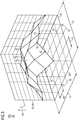
- FIG. 2 shows a machining of the workpiece 20 with a tool 10 of a production machine 50, in which the workpiece 20 is aligned by means of the method 100 according to the invention.
- the workpiece 20 is positioned on a workpiece table 22 and has at a corner a workpiece reference point 24, which serves as the origin for a plurality of workpiece axes 25.
- the workpiece reference point 24 and the workpiece axes 25 together form the tool coordinate system to which the machining path 27 traveled by the tool 10 is defined.
- the machining path 27 is composed of sections whose respective direction of movement 26 is parallel to one of the workpiece axes 25.
- FIG. 2 shows the machine reference point 52, which serves as the origin for the machine axes 53.
- the machine axes 53 and the machine reference point 52 together form the machine coordinate system.
- the workpiece reference point 24 is spaced from the machine reference point 52 by a translational offset 32, which is a parameter of a rigid transformation 30, by which movements in the machine coordinate system 57 and in the workpiece coordinate system 28 are interconvertible.
- the rigid transformation 30 further includes an orientation angle 34 that lies between one of the machine axes 53 and one of the workpiece axes 25. The workpiece 20 is thus rotated on the workpiece table 22 by the orientation angle 34.
- the tool 10 moves along a section of the machining path 27, the tool 10 is moved along two machine axes 53.
- An actuating direction of a drive means 54 corresponds to each of the machine axes 53.
- the individual sections of the machining path 27 are related to the machine coordinate system 57 essentially diagonally.
- the machining forces generated by the drive means 54 are superimposed on the workpiece 20.
- the axis dynamics that is speed, acceleration and jerk, overlap, resulting in faster path movements with respect to the workpiece 20.
- FIG. 3 a diagram of a process variable evaluation of a second embodiment of the inventive method 100 is shown.
- the diagram comprises a first parameter axis 38, on which a first parameter 35 of a rigid transformation 30 with respect to a zero line 37 is plotted.
- the diagram also includes a second parameter axis 39 on which a second parameter 36 of the rigid transformation 30 is plotted relative to a zero line 37.
- the parameter axes 38, 39 span a plane in which the associated parameters 35, 36 are each modified within a variation width 47. The modification of the parameters 35, 36 takes place in separate step sizes 48, 49.
- An intersection point 45 of two values of the parameters 35, 36 in the plane spanned by the parameter axes 38, 39 corresponds to a rigid transformation 30, for the workpiece-fixed processing path 27 not shown in detail in the method 100 according to the invention taking into account the respective rigid transformation 30 is simulated.
- the process variable 40 is plotted along a process variable axis 44, which is determined by the associated simulation.
- the process variable axis 44 also has a zero line 37.
- a support point 42 corresponds to each of the intersection points 45 in the plane spanned by the parameter axes 38, 39.
- the plurality of interpolation points 42 define a segmented result surface 41, by means of which the rigid transformation 30 in which the process variable 40 reaches the selectable target value 43. According to FIG. 3 the selected target value 43 is a maximum of the process variable 40.
- FIG. 4 1 schematically shows a diagram of a third embodiment of the method 100 according to the invention.
- the diagram comprises a first parameter axis 38, on which a first parameter 35 of a rigid transformation 30 relative to a zero line 37 is plotted.
- the diagram also includes a second parameter axis 39 on which a second parameter 36 of the rigid transformation 30 is plotted relative to a zero line 37.
- the parameter axes 38, 39 span a plane in which the associated parameters 35, 36 are each modified within a variation width 47. The modification of the parameters 35, 36 takes place in separate step sizes 48, 49.
- An intersection point 45 of two values of the parameters 35, 36 in the plane spanned by the parameter axes 38, 39 corresponds to a rigid transformation 30, for which in the invention Method 100, the workpiece-fixed processing path 27, not shown in detail, taking into account the respective rigid transformation 30 is simulated.
- the process variable 40 is plotted along a process variable axis 44, which is determined by the associated simulation.
- the process variable axis 44 also has a zero line 37.
- a support point 42 corresponds to each of the intersection points 45 in the plane spanned by the parameter axes 38, 39.
- the support points 43 serve as data for creating a least-square polynomial with which the continuous result area 31 is determined.
- the support points 42 can also lie outside of the result surface 41 with a tolerance 33 along the process variable axis 44.
- a desired maximum or minimum can also be determined in a simple manner in a region between the support points 43.
- FIG. 5 a flowchart 5 of a fourth embodiment of the method 100 according to the invention is shown.
- a workpiece-fixed machining path 27 of the workpiece not shown in more detail 20, which is to be machined.
- a selection step 120 in which a rigid transformation 30 of the positioning of the workpiece 20 is selected.
- the rigid transformation 30 describes in which position and orientation the workpiece 20 is clamped in the production machine 50, not shown in the machining.
- a simulation step 130 in which the workpiece-fixed machining path 27 is traversed in a simulation taking into account the rigid transformation 30 selected in the previous method step 120.
- the workpiece-fixed processing path 27 is traversed when the workpiece 20 is clamped in accordance with the rigid transformation 30.
- a subsequent evaluation step 140 at least one process variable 40 is determined, which results from the selected machining of the workpiece 20.
- the process variable 40 may be, for example, a ratio of operating times of drive means 54 on different machine axes 53 of the production machine 50.
- a test step 145 in which it is checked whether the at least process variable 40 determined in the preceding evaluation step 140 reaches a selected target value 43.
- the target value 43 is a maximum, a minimum, or a selectable value.
- the corresponding rigid transformation 30 is output to a user as a result of the inventive method 100 at the end of the process 150.
- a return 160 of the method 100 according to the invention to the selection step 120 and a new passage of the method 100 is carried out.
- a different rigid transformation 30 is selected in the selection step 120 than in the previous pass.
- the rigid transformation 30 is modified for the new passage by at least a parameter 35, 36 of the rigid transformation 30 is changed.
Landscapes
- Engineering & Computer Science (AREA)
- Human Computer Interaction (AREA)
- Manufacturing & Machinery (AREA)
- Physics & Mathematics (AREA)
- General Physics & Mathematics (AREA)
- Automation & Control Theory (AREA)
- Numerical Control (AREA)
Description
Die Erfindung betrifft ein Verfahren zur Ausrichtung eines Werkstücks, sowie ein dazu geeignetes Programm, eine geeignete Steuereinheit, und eine entsprechende Produktionsmaschine. Es ist eine Vielzahl an Bearbeitungsverfahren für Werkstücke bekannt, bei denen ein NC- oder CNC-gesteuertes Werkzeug oder Werkzeugersatz, beispielsweise eine Laser-Punkt oder eine Druckerspitze, relativ zum Werkstück auf einer Bahn entlang geführt wird. Dabei ist das Werkzeug und/oder das Werkstück entlang seiner Hauptachsausrichtungen durch eine Mehrzahl an Antriebsmitteln angetrieben, deren Aufbau die erzielbare Bearbeitungsleistung bestimmen. Es ist ferner bekannt, dass durch eine modifizierte räumliche Ausrichtung eines zu bearbeitenden Werkstücks bezüglich zur Ausrichtung der Hauptachsen bei der Bearbeitung eine Zeitersparnis erzielt werden kann. Hierzu wird beispielsweise das Werkstück um einen bestimmten Winkel gedreht eingespannt. Der entsprechende Winkel wird hierbei durch manuelles Ausprobieren durch einen Benutzer ermittelt.The invention relates to a method for aligning a workpiece, as well as a suitable program, a suitable control unit, and a corresponding production machine. There are a variety of machining processes for workpieces known in which an NC or CNC-controlled tool or tool replacement, such as a laser dot or a printing tip, is guided relative to the workpiece along a path. In this case, the tool and / or the workpiece is driven along its Hauptachsausrichtungen by a plurality of drive means whose structure determine the achievable machining performance. It is also known that a time savings can be achieved by a modified spatial orientation of a workpiece to be machined with respect to the alignment of the major axes during processing. For this example, the workpiece is rotated rotated by a certain angle. The corresponding angle is determined by manual trial by a user.
Es besteht ein Nachteil darin, dass eine derartige experimentelle Ermittlung zeitaufwändig ist. Hierdurch wird häufig nicht das theoretisch erreichbare Maximum an Zeitersparnis erzielt. Insgesamt besteht Bedarf an einer Lösung, die einem Benutzer ohne experimentellen Aufwand eine optimierte Ausrichtung eines Werkstücks ermittelt.There is a disadvantage in that such an experimental determination is time consuming. This often does not achieve the theoretically achievable maximum time savings. Overall, there is a need for a solution that provides a user with no experimental effort to optimize alignment of a workpiece.
Die Offenlegungsschrift:
Die Aufgabe wird durch das erfindungsgemäße Verfahren gelöst, bei dem eine angestrebte Ausrichtung eines Werkstücks ermittelt wird, das einer Bearbeitung zu unterziehen ist. Dabei wird in einem ersten Schritt von einer Steuereinheit einer Produktionsmaschine ein werkstückfester Bearbeitungspfad bereitgestellt, den ein Werkzeug der Produktionsmaschine zur Anfertigung des angestrebten Produkts abzufahren hat. Der werkstückfeste Bearbeitungspfad ist hierbei auf einen Werkstückbezugspunkt bezogen und in einem zugehörigen Werkstückachsensystem definiert. Insgesamt ist der werkstückfeste Bearbeitungspfad damit in einem körperfesten Bezugssystem definiert. In einem weiteren Verfahrensschritt wird eine starre Transformation der Positionierung des Werkstücks ausgewählt. Unter der starren Transformation ist hierbei die Lage des Werkstückbezugspunktes relativ zum Produktionsmaschinenbezugspunkt im zugehörigen Werkzeugachsensystem zu verstehen. Die starre Transformation umfasst ferner die Ausrichtung des Werkstückachsensystems im Produktionsmaschinenachsensystem. Das Auswählen der starren Transformation erfolgt durch ein Programm, das in der Steuereinheit der Werkzeugsteuermaschine ausgeführt wird. In einem anschließenden Verfahrensschritt wird das Abfahren des werkstückfesten Bearbeitungspfades unter Berücksichtigung der starren Transformation der Werkstückpositionierung durchgeführt. Bei der Simulation wird mindestens ein zugehöriger Steuerbefehl für mindestens ein Antriebsmittel der Produktionsmaschine berechnet und gespeichert. In einem anschließenden Verfahrensschritt wird der ermittelte mindestens eine Steuerbefehl ausgewertet, so dass eine zeitlich aufgelöste Beanspruchung der Antriebsmittel der Produktionsmaschine erkennbar ist. Auf Basis dessen wird mindestens eine Prozessgröße ermittelt, die das Abfahren des werkstückfesten Bearbeitungspfades bei der Bearbeitung charakterisiert.The object is achieved by the method according to the invention, in which determines a desired orientation of a workpiece which is to undergo a processing. In this case, in a first step, a work piece-fixed processing path is provided by a control unit of a production machine, which a tool of the production machine has to run to produce the desired product. The workpiece-fixed processing path is in this case based on a workpiece reference point and defined in an associated workpiece axis system. Overall, the workpiece-fixed machining path is thus defined in a body-fixed reference system. In a further method step, a rigid transformation of the positioning of the workpiece is selected. Under the rigid transformation here is the position of the workpiece reference point relative to the production machine reference point in the associated tool axis system to understand. The rigid transformation further comprises the alignment of the workpiece axis system in the production machine axis system. The selection of the rigid transformation is made by a program executed in the control unit of the tool control machine. In a subsequent method step, the traversing of the workpiece-fixed machining path is carried out taking into account the rigid transformation of the workpiece positioning. In the simulation, at least one associated control command for at least one drive means of the production machine is calculated and stored. In a subsequent method step, the determined at least one control command is evaluated, so that a time-resolved stress of the drive means of the production machine can be seen. Based on this, at least one process variable is determined, which characterizes the departure of the workpiece-fixed machining path during machining.
Erfindungsgemäß werden die beschriebenen Schritte unter Modifizieren der starren Transformation der Werkstückpositionierung wiederholt und dabei jeweils die zugehörige Prozessgröße ermittelt. Das Wiederholen der Verfahrensschritte erfolgt solange, bis die mindestens eine Prozessgröße einen angestrebten Zielwert erreicht.According to the invention, the described steps are repeated by modifying the rigid transformation of the workpiece positioning and in each case the associated process variable is determined. The process steps are repeated until the at least one process variable reaches a desired target value.
Das erfindungsgemäße Verfahren erlaubt es, in kurzer Zeit eine Vielzahl an Ausrichtungen des Werkstücks auszuwerten und eine geeignete Ausrichtung auszuwählen. Die auszuwertende Prozessgröße kann dabei durch den Benutzer gewählt werden, so dass eine Optimierung auf eine Vielzahl von Aspekten möglich ist. Ferner nutzt das erfindungsgemäße Verfahren mit dem Bearbeitungspfad eine zur Verarbeitung des Werkstücks notwendige Information, die ohnehin vorliegt. Darüber hinaus erfolgt die Simulation des mit der starren Transformation beaufschlagten Bearbeitungspfades in einem Softwaremodul, das in einer Steuereinheit einer modernen Produktionsmaschine ohnehin vorhanden ist.The method according to the invention makes it possible to evaluate a large number of orientations of the workpiece in a short time and to select a suitable alignment. The process variable to be evaluated can be selected by the user, so that an optimization on a variety of aspects is possible. Furthermore, the method according to the invention uses, with the processing path, information necessary for processing the workpiece, which is present anyway. In addition, the simulation of the processing path subjected to the rigid transformation takes place in a software module which is present in any case in a control unit of a modern production machine.
Der Erfindung liegt dabei die überraschende Erkenntnis zugrunde, dass bereits mit einer geringen Anzahl an Simulationsdurchläufen eine der angestrebten Prozessgröße zuträgliche Ausrichtung ermittelt wird. Die geringe Anzahl an Simulationsdurchläufen erlaubt es, das beanspruchte Verfahren auch auf einfacher Hardware mit geringer Rechenleistung umzusetzen. Infolgedessen kann das erfindungsgemäße Verfahren in einfacher und kostengünstiger Weise verwirklicht werden. Erfindungsgemäß ist die mindestens eine Prozessgröße ein Verhältnis von Betriebsdauern der Antriebsmittel von mindestens zwei Werkzeugbewegungsachsen.The invention is based on the surprising finding that even with a small number of simulation runs, one of the desired process variable-beneficial orientation is determined. The small number of simulation runs makes it possible to implement the claimed method even on simple hardware with low computing power. As a result, the method according to the invention can be realized in a simple and cost-effective manner. According to the invention, the at least one process variable is a ratio of operating times of the drive means of at least two tool movement axes.
In einer bevorzugten Ausführungsform der Erfindung umfasst die starre Transformation als Parameter einen translatorischen Versatz und/oder einen Ausrichtungswinkel des Werkstücks. Der translatorische Versatz ist dabei die Position des Werkstückbezugspunktes relativ zum Maschinenbezugspunkt in dessen Maschinenachsensystem. Der Ausrichtungswinkel beschreibt, unter welchem Winkel sich Achsen des Werkstückachsensystems und des Maschinenachsensystems schneiden. Bei einer parallelen Ausrichtung der beiden Achsensysteme nehmen alle Ausrichtungswinkel den Wert Null Grad an. Gleichermaßen ist der translatorische Versatz Null, wenn der Werkstückbezugspunkt in den Maschinenbezugspunkt fällt. Eine Darstellung der starren Transformation als eine Kombination aus einem translatorischen Versatz und mindestens einen Ausrichtungswinkel erlaubt eine kompakte Darstellung der starren Transformation, so dass das erfindungsgemäße Verfahren schnell durchgeführt werden kann. Die Parameter spiegeln wieder, in welcher Ausrichtung das Werkstück für die Bearbeitung einzuspannen ist. Durch eine Auswahl bzw. Einschränkung der zu modifizierenden und simulierenden Ausrichtungswinkel können die bei der Einspannung verwirklichbaren technischen Möglichkeiten abgebildet werden. Infolgedessen kann das erfindungsgemäße Verfahren auf Werkstückpositionierungen beschränkt werden, die in einfacher Weise realisierbar sind. Hierdurch wird die Effizienz des beanspruchten Verfahrens weiter gesteigert.In a preferred embodiment of the invention, the rigid transformation comprises as parameters a translational offset and / or an orientation angle of the workpiece. The translational offset is the position of the workpiece reference point relative to the machine reference point in the machine axis system. The orientation angle describes the angle at which axes of the workpiece axis system and the machine axis system intersect. In a parallel alignment of the two axis systems, all alignment angles take on the value zero degrees. Likewise, the translational offset is zero when the workpiece reference point falls within the machine reference point. A representation of the rigid transformation as a combination of a translational offset and at least one orientation angle allows a compact representation of the rigid transformation, so that the inventive method can be performed quickly. The parameters reflect the alignment in which the workpiece is to be clamped for machining. By selecting or restricting the orientation angles to be modified and simulated, the technical possibilities that can be realized during clamping can be mapped. As a result, the inventive method can be limited to workpiece positioning, which can be realized in a simple manner. As a result, the efficiency of the claimed method is further increased.
In einer besonders bevorzugten Ausführungsform der Erfindung ist das Verhältnis der Betriebsdauern der Antriebsmittel der mindestens zwei Maschinenachsen im Wesentlichen gleich Eins. Damit bildet das Verhältnis der Betriebsdauern der beiden Antriebsmittel die Gleichmäßigkeit des Verschleißes an. Hierdurch erlaubt das erfindungsgemäße Verfahren, durch Auswahl einer entsprechenden Werkstückpositionierung dessen Bearbeitung an die Robustheit der einzelnen Antriebsmittel der Produktionsmaschine anzupassen. Hierdurch werden die Ausfallzeiten an der Produktionsmaschine minimiert, und die Wirtschaftlichkeit der spanenden Verarbeitung des Werkstücks gesteigert. Je gleichmäßiger der Verschleiß an den Antriebsmitteln der Produktionsmaschine auftritt, umso geringer werden dabei die Ausfallzeiten.In a particularly preferred embodiment of the invention, the ratio of the operating times of the drive means of the at least two machine axes is substantially equal to one. Thus, the ratio of the service life of the two drive means forms the uniformity of wear. As a result, the method according to the invention allows, by selecting a corresponding workpiece positioning, to adapt its machining to the robustness of the individual drive means of the production machine. This minimizes downtime on the production machine and increases the economics of machining the workpiece. The more uniform the wear on the drive means of the production machine, the lower the downtime.
Befinden sich bei einer Bearbeitung, beispielsweise mit einem Fräser, zwei Antriebsmittel der Produktionsmaschine gleichzeitig im Eingriff, können die Antriebskräfte beider Antriebsmittel gleichzeitig auf das Werkzeug aufgebracht werden. Durch das gleichzeitige Aufbringen mehrerer Antriebskräfte ist eine erhöhte Bearbeitungsgeschwindigkeit, beispielsweise eine erhöhte Schnittgeschwindigkeit, erzielbar. Die durch Kombination zweier Antriebsmittel erzielbare Bearbeitungsgeschwindigkeit ist höher als die mit nur einem Antriebsmittel erzielbare Bearbeitungsgeschwindigkeit. Alternativ oder ergänzend kann durch eine solche Kombination von mehreren Antriebskräften auch eine Energieersparnis oder Verschleißminderung erreicht werden. Das erfindungsgemäße Verfahren erlaubt es damit, das Leistungspotential einer Produktionsmaschine stärker auszuschöpfen und die Wirtschaftlichkeit der Bearbeitung des Werkstücks weiter zu erhöhen.If, during machining, for example with a milling cutter, two drive means of the production machine are engaged at the same time, the drive forces of both drive means can be applied simultaneously to the tool. Due to the simultaneous application of several driving forces, an increased processing speed, for example an increased cutting speed, can be achieved. The achievable by combining two drive means processing speed is higher than the achievable with only one drive means processing speed. alternative or in addition can be achieved by such a combination of several driving forces and energy savings or reduction in wear. The method according to the invention thus makes it possible to better exploit the performance potential of a production machine and to further increase the cost-efficiency of machining the workpiece.
In der Ausführungsform der Erfindung ist der Zielwert, auf den mindestens eine Prozessgröße optimiert wird, ein wählbarer Wert. Hierdurch ist das erfindungsgemäße Verfahren in einfacher Weise an eine Vielzahl an Prozessgrößen anpassbar. Beispielsweise kann auch eine minimale Zeitdauer für die Bearbeitung des Werkstücks, ein minimaler Energieverbrauch, oder eine maximale Bearbeitungsgeschwindigkeit des Werkzeugs angestrebt werden. Infolgedessen ist das beanspruchte Verfahren an eine Vielzahl von Einsatzbereichen anpassbar.In the embodiment of the invention, the target value to which at least one process variable is optimized is a selectable value. As a result, the method according to the invention can be adapted in a simple manner to a large number of process variables. For example, a minimum amount of time for machining the workpiece, a minimum power consumption, or a maximum machining speed of the tool can be sought. As a result, the claimed method is adaptable to a variety of applications.
In einer weiteren Ausführungsform der Erfindung werden die oben beschriebenen Verfahrensschritte für mindestens einen wählbaren Parameter der starren Transformation mindestens dreimal iterativ durchgeführt. Dabei wird der mögliche Wertebereich des wählbaren Parameters in mindestens zwei Intervalle eingeteilt. Auch bei einer Kombination von mehreren wählbaren Parametern bleibt die Anzahl der erforderlichen Simulationsdurchgänge gering. Gleichermaßen ist die Anzahl der ermittelten Werte für die Prozessgröße gering, so dass mit wenig Rechenaufwand darin ein Maximum, ein Minimum oder ein gewählter Zielwert identifiziert werden kann. So kann beispielsweise eine Optimierung anhand von zwei Parametern der starren Transformation durch sechs Simulationen von werkstückfesten Bearbeitungspfaden und jeweils anschließender Ermittlung der mindestens einen Prozessgröße erfolgen, wenn beide Parameter nacheinander separat modifiziert werden. Ferner kann eine Optimierung anhand von zwei Parametern mit neun Simulationen von werkstückfesten Bearbeitungspfaden und Ermittlungen der mindestens einen Prozessgröße durchgeführt werden, wenn jeder Parameterwert des ersten Parameters der starren Transformation mit allen Parameterwerten des zweiten Parameters der starren Transformation zu kombinieren ist. Hierdurch wird der erforderliche Rechenaufwand und die Anforderungen an die dazu eingesetzte Hardware durch das erfindungsgemäße Verfahren ohne Einbuße an Präzision weiter verringert.In a further embodiment of the invention, the method steps described above are performed at least three times iteratively for at least one selectable parameter of the rigid transformation. The possible value range of the selectable parameter is divided into at least two intervals. Even with a combination of several selectable parameters, the number of required simulation runs remains low. Similarly, the number of values determined for the process variable is small, so that a maximum, a minimum or a selected target value can be identified therein with little computational effort. Thus, for example, an optimization based on two parameters of the rigid transformation by six simulations of workpiece-fixed processing paths and each subsequent determination of at least one process variable done if both parameters are modified separately in succession. Furthermore, an optimization can be carried out on the basis of two parameters with nine simulations of workpiece-fixed machining paths and determinations of the at least one process variable, if each parameter value of the first parameter of the rigid transformation is to be combined with all parameter values of the second parameter of the rigid transformation. As a result, the required computing effort and the requirements for the hardware used for this purpose is further reduced by the method according to the invention without any loss of precision.
In einer weiteren Ausführungsform des erfindungsgemäßen Verfahrens ist der Zielwert ein Resultat einer nichtlinearen Optimierung, eines Newton-Verfahrens oder ist ein Optimum eines Least-Square-Polynoms.In a further embodiment of the method according to the invention, the target value is a result of a nonlinear optimization, a Newton's method or is an optimum of a least square polynomial.
Besonders bevorzugt dienen die bei jeder Modifikation der starren Transformation errechneten Prozessgrößen als Stützstellen für die nichtlineare Optimierung, das Newton-Verfahren oder das Least-Square-Polynom. Bei diesen Rechenverfahren wird im Wesentlichen eine mathematisch beschriebene Kurve oder Fläche durch die Stützstellen gelegt. Solche Kurven oder Flächen sind mathematisch mit geringem Rechenaufwand analytisch auswertbar, so dass in einfacher Weise ein Maximum, ein Minimum oder ein Wertebereich ermittelbar ist. Insbesondere sind Maxima, Minima oder Zielbereiche, die zwischen den Stützstellen liegen, identifizierbar. Eine derartige Auswahl eines zwischen den Stützstellen liegenden Zielwertes erlauben es, den Zeitbedarf für die Bearbeitung oder deren Energiebedarf weiter zu senken. Die Rechenverfahren können ohne Weiteres auch zur Ermittlung eines Optimums in Abhängigkeit einer Vielzahl von Parametern der starren Transformation ermittelt werden. Infolge dessen kann eine Anzahl an Ausrichtungen des Werkstücks in der Einspannung ausgewertet werden, die für eine experimentelle Ermittlung einer optimierten Werkstückpositionierung unpraktikabel hoch ist. Beispielsweise kann infolge einer um mehrere Raumachsen gedrehten Ausrichtung des Werkstücks eine Überlagerung von Antriebsmitteln von drei oder mehr Werkzeugachsen erzielt werden, was zu einer erhöhten Bearbeitungsgeschwindigkeit führt. Die nichtlineare Optimierung, das Newton-Verfahren und das Least-Square-Polynom erlauben damit, die technischen Kapazitäten der Produktionsmaschine weiter auszuschöpfen und die Effizienz der Werkstückbearbeitung weiter zu steigern. Dabei basiert das erfindungsgemäße Verfahren auf einer niedrigen Anzahl an Iterationsschritten und bedient sich einfacher mathematischer Auswertungsmethoden, die auch mit einfacher Hardware umsetzbar sind.Particularly preferably, the process variables calculated with each modification of the rigid transformation serve as support points for the nonlinear optimization, the Newton method or the least square polynomial. In this calculation method, a mathematically described curve or surface is essentially laid through the support points. Such curves or surfaces can be analytically evaluated with little computational effort, so that a maximum, a minimum or a value range can be determined in a simple manner. In particular, maxima, minima or target areas lying between the support points can be identified. Such a selection of a target value lying between the interpolation points makes it possible to further reduce the time required for processing or their energy requirement. The calculation methods can also be determined without difficulty for determining an optimum as a function of a multiplicity of parameters of the rigid transformation. As a result, a number of orientations of the workpiece in the chuck can be evaluated, which is impractically high for an experimental determination of an optimized workpiece positioning. For example, as a result of an orientation of the workpiece rotated about several spatial axes, a superposition of drive means of three or more tool axes can be achieved, which leads to an increased processing speed. The nonlinear optimization, the Newton method and the least-square polynomial thus allow the technical capabilities of the production machine continue to exploit and further increase the efficiency of workpiece machining. The method according to the invention is based on a low number of iteration steps and makes use of simple mathematical evaluation methods which can also be implemented with simple hardware.
In einer weiteren besonders bevorzugten Ausführungsform der Erfindung wird bei einem ersten Durchlauf ein erster Parameter der starren Transformation modifiziert. Wenn beim ersten Durchlauf die Differenzen der Werte der mindestens einen Prozessgröße zu ihrem Zielwert einen Schwellenwert übersteigen, wird dies als ein Stillstand der angestrebten Optimierung identifiziert. Anschließend wird in einem anschließenden zweiten Durchlauf ein zweiter Parameter der starren Transformation modifiziert und anhand von Differenzen der ermittelten Werte der mindestens einen Prozessgröße eine Annäherung an den Zielwert bzw. ein weiterer Stillstand der angestrebten Optimierung identifiziert. Zusätzlich können in weiteren Durchläufen weitere Parameter der starren Transformation modifiziert werden. Beispielsweise kann als erster Parameter die Drehung des Werkstücks um eine Achse senkrecht zu einem Werkstücktisch verändert werden. Ein derartiges Drehen und Einspannen des Werkstücks in der Werkstücktischebene kann mit einfachen Mitteln umgesetzt werden. Besonders bevorzugt ist der erste Parameter der starren Transformation, der im ersten Durchlauf modifiziert wird, die geometrische Größe, die durch ein Spannzeug am Werkstücktisch am einfachsten umgesetzt werden kann. Der erste Parameter ist besonders bevorzugt ein Drehwinkel um eine Werkstückachse, die im Wesentlichen senkrecht zur Ebene des Werkstücktischs steht. Wenn beim ersten Durchlauf der angestrebte Zielwert nicht erreicht wird, oder zumindest keine Annäherung daran erfolgt, werden im zweiten Durchlauf durch Modifizieren des zweiten Parameters Ausrichtungen des Werkstücks ausgewertet, die ein aufwändigeres Spannzeug erfordern. Je mehr Parameter der starren Transformation für eine optimale Werkstückpositionierung anzupassen sind, umso höher sind die Anforderungen an das erforderliche Spannzeug. Das erfindungsgemäße Verfahren verwirklicht durch das sukzessive Modifizieren einzelner Parameter der starren Transformation das Prinzip einer stufenweisen Parameter-Variation. Die Reihenfolge, welcher Parameter der starren Transformation im ersten, im zweiten, dritten, usw. Durchlauf modifiziert wird, ist durch den Benutzer auswählbar. Infolge dessen kann der Benutzer das erfindungsgemäße Verfahren daran anpassen, welcher Aufwand im vorliegenden Bearbeitungsverfahren für ein Spannzeug gerechtfertigt ist. Das erfindungsgemäße Verfahren ist folglich in einfacher Weise an eine Vielzahl von Anwendungsfällen anpassbar und dadurch in besonderem Maße wirtschaftlich.In a further particularly preferred embodiment of the invention, in a first pass, a first parameter of the rigid transformation is modified. If, during the first pass, the differences of the values of the at least one process variable from its target value exceed a threshold value, this is identified as a stoppage of the desired optimization. Subsequently, in a subsequent second pass, a second parameter of the rigid transformation is modified and, based on differences in the determined values of the at least one process variable, an approximation to the target value or a further standstill of the desired optimization is identified. In addition, further parameters of the rigid transformation can be modified in further runs. For example, as a first parameter, the rotation of the workpiece about an axis perpendicular to a workpiece table can be changed. Such a rotation and clamping of the workpiece in the workpiece table level can be implemented by simple means. Particularly preferably, the first parameter of the rigid transformation, which is modified in the first pass, is the geometrical variable which can be most easily implemented by a gripping tool on the workpiece table. The first parameter is particularly preferably a rotation angle about a workpiece axis, which is substantially perpendicular to the plane of the workpiece table. If, during the first pass, the desired target value is not reached, or at least no approximation takes place, in the second pass, by modifying the second parameter, alignments of the workpiece are evaluated which require a more complex clamping tool. The more parameters of the rigid transformation are to be adapted for optimal workpiece positioning, the higher are the requirements for the required Grips. The method according to the invention realizes the principle of a stepwise parameter variation by successively modifying individual parameters of the rigid transformation. The order which parameter of the rigid transformation is modified in the first, second, third, etc., pass is user selectable. As a result, the user can adapt the method according to the invention to the expense which is justified in the present machining method for a clamping device. The inventive method is thus easily adaptable to a variety of applications and thus particularly economical.
In einer weiteren Ausführungsform der Erfindung wird im Verfahrensschritt, in dem der werkstückfeste Bearbeitungspfad unter Berücksichtigung der starren Transformation der Werkstückposition erfolgt, mindestens eine Randbedingung der Produktionsmaschine berücksichtigt. Die Randbedingung der Produktionsmaschine kann dabei eine maximale Fahrlänge, eine maximale Beschleunigung, ein maximaler Ruck und/oder eine maximale Bearbeitungsgeschwindigkeit des Werkzeugs bzw. Werkstücks entlang mindestens einer Werkzeugachse oder Werkstückachse sein. Wird dabei eine Verletzung einer solchen Randbedingung erkannt, wird die korrespondierende starre Transformation für die weitere Durchführung des erfindungsgemäßen Verfahrens verworfen.In a further embodiment of the invention, at least one boundary condition of the production machine is taken into account in the method step in which the workpiece-fixed machining path takes place taking into account the rigid transformation of the workpiece position. The boundary condition of the production machine can be a maximum travel length, a maximum acceleration, a maximum jerk and / or a maximum processing speed of the tool or workpiece along at least one tool axis or workpiece axis. If a violation of such a boundary condition is detected, the corresponding rigid transformation for the further implementation of the method according to the invention is discarded.
Die der Erfindung zugrunde liegende Aufgabe wird ferner durch ein Programm gelöst, das in einem Speicher einer Steuereinheit einer Produktionsmaschine speicherbar ist, und durch ein Rechenwerk in der Steuereinheit ausführbar ist. Das erfindungsgemäße Programm ist dazu ausgebildet, Steuerbefehle an Antriebsmittel von Werkzeugachsen der Produktionsmaschine auszugeben. Erfindungsgemäß ist das Programm ferner dazu geeignet, mindestens eines der oben stehenden Verfahren durchzuführen. Das erfindungsgemäße Programm basiert dabei auf Softwarekomponenten, wie beispielsweise einem Simulationsmodul, die in einer Steuereinheit einer Produktionsmaschine ohnehin vorhanden sind, und erfordert selbst nur geringe Rechenleistung. Infolgedessen kann eine Produktionsmaschine in einfacher Weise mit dem erfindungsgemäßen Programm nachgerüstet werden. Das Programm ist damit für eine weite Spanne an Einsatzzwecken geeignet und erlaubt eine preiswerte leistungssteigernde Modifikation vorhandener Produktionsmaschinen.The object underlying the invention is further achieved by a program that can be stored in a memory of a control unit of a production machine, and by an arithmetic unit in the control unit executable. The program according to the invention is designed to output control commands to drive means of tool axes of the production machine. According to the invention, the program is also suitable for carrying out at least one of the above-mentioned methods. The program according to the invention is based on software components, such as a simulation module, in any case in a control unit of a production machine are present, and requires only low computing power. As a result, a production machine can be easily retrofitted with the program according to the invention. The program is thus suitable for a wide range of applications and allows a low-cost performance-enhancing modification of existing production machines.
Die der Erfindung zugrundeliegende Aufgabe wird auch durch eine Steuereinheit gelöst, die dazu geeignet ist, mindestens ein Antriebsmittel einer Produktionsmaschine zu steuern. Die Steuereinheit weist dazu einen Speicher und eine Recheneinheit zur Ausführung eines Programms auf. Das Programm ist dazu ausgebildet, mindestens eines der oben stehenden erfindungsgemäßen Verfahren durchzuführenThe object underlying the invention is also achieved by a control unit which is suitable for controlling at least one drive means of a production machine. The control unit has for this purpose a memory and a computing unit for executing a program. The program is designed to carry out at least one of the above inventive methods
Gleichermaßen wird die der Erfindung zugrundeliegende Aufgabenstellung durch eine Produktionsmaschine gelöst, die ein Werkzeug umfasst, das durch jeweils mindestens ein Antriebsmittel entlang mindestens zweier Werkzeugachsen oder Werkstückachsen bewegbar ist. Ferner umfasst die Produktionsmaschine eine Steuereinheit mit einem Speicher, auf dem das oben beschriebene erfindungsgemäße Programm gespeichert und ausgeführt werden kann. Die erfindungsgemäße Produktionsmaschine ist dazu geeignet, eine Bearbeitung eines Werkstücks mit einem Minimum an Zeitbedarf, einem Minimum an Energiebedarf und/oder einem Minimum an Verschleiß an den Antriebsmitteln durchzuführen.Similarly, the problem underlying the invention is achieved by a production machine comprising a tool which is movable by at least one drive means along at least two tool axes or workpiece axes. Furthermore, the production machine comprises a control unit with a memory on which the program according to the invention described above can be stored and executed. The production machine according to the invention is suitable for carrying out a machining of a workpiece with a minimum of time requirement, a minimum of energy requirement and / or a minimum of wear on the drive means.
Die Erfindung wird im Folgenden anhand einzelner Ausführungsformen in den Figuren näher beschrieben: Es zeigt:
- FIG 1
- eine Werkstückbearbeitung nach dem Stand der Technik;
- FIG 2
- eine Werkstückbearbeitung mit einer Werkstückpositionierung aus einer ersten Ausführungsform des erfindungsgemäßen Verfahrens;
- FIG 3
- ein Diagramm einer Prozessgrößenauswertung gemäß einer zweiten Ausführungsform der Erfindung;
- FIG 4
- eine Prozessgrößenauswertung gemäß einer dritten Ausführungsform des erfindungsgemäßen Verfahrens;
- FIG 5
- schematisch ein Ablaufdiagramm einer vierten Ausführungsform des erfindungsgemäßen Verfahrens.
- FIG. 1
- a workpiece machining according to the prior art;
- FIG. 2
- a workpiece machining with a workpiece positioning of a first embodiment of the method according to the invention;
- FIG. 3
- a diagram of a process variable evaluation according to a second embodiment of the invention;
- FIG. 4
- a process variable evaluation according to a third embodiment of the method according to the invention;
- FIG. 5
- schematically a flowchart of a fourth embodiment of the method according to the invention.
In
In
Ein Schnittpunkt 45 von zwei Werten der Parameter 35, 36 in der von den Parameter-Achsen 38, 39 aufgespannten Ebene korrespondiert mit einer starren Transformation 30, für die im erfindungsgemäßen Verfahren 100 der nicht näher dargestellte werkstückfeste Bearbeitungspfad 27 unter Berücksichtigung der jeweiligen starren Transformation 30 simuliert wird. Zu jedem Schnittpunkt 45 wird entlang einer Prozessgrößen-Achse 44 die Prozessgröße 40 aufgetragen, die durch die zugehörige Simulation ermittelt wird. Die Prozessgrößen-Achse 44 weist auch eine Null-Linie 37 auf. Mit jedem der Schnittpunkte 45 in der von den Parameter-Achsen 38, 39 aufgespannten Ebene korrespondiert eine Stützstelle 42. Die Mehrzahl an Stützstellen 42 definiert eine segmentierte Resultatfläche 41, anhand der im erfindungsgemäßen Verfahren 100 die starre Transformation 30 ermittelt wird, bei dem die Prozessgröße 40 den wählbaren Zielwert 43 erreicht. Gemäß
Die Stützstellen 43 dienen als Daten zur Erstellung eines Least-Square-Polynoms, mit dem die stetige Resultatfläche 31 ermittelt wird. Bei der Ermittlung der stetigen Resultatfläche 41 können die Stützstellen 42 auch mit einer Toleranz 33 entlang der Prozessgrößen-Achse 44 außerhalb der Resultatfläche 41 liegen. Auf der stetigen Resultatfläche 31 kann ein angestrebtes Maximum oder Minimum auch in einem Bereich zwischen den Stützstellen 43 in einfacher Weise ermittelt werden.The support points 43 serve as data for creating a least-square polynomial with which the continuous result area 31 is determined. When determining the
In
In einem darauffolgenden Evaluationsschritt 140 wird mindestens eine Prozessgröße 40 ermittelt, die sich aus der gewählten spanenden Bearbeitung des Werkstücks 20 ergibt. Die Prozessgröße 40 kann dabei beispielsweise ein Verhältnis von Betriebsdauern von Antriebsmitteln 54 an unterschiedlichen Maschinenachsen 53 der Produktionsmaschine 50 sein. Daran schließt sich ein Prüfschritt 145 an, in dem geprüft wird, ob die im vorangegangenen Evaluationsschritt 140 ermittelte mindestens Prozessgröße 40 einen gewählten Zielwert 43 erreicht. Der Zielwert 43 ist dabei ein Maximum, ein Minimum, oder ein wählbarer Wert. Wenn der angestrebte Zielwert 43 erreicht ist, wird die korrespondierende starre Transformation 30 einem Benutzer als Ergebnis des erfindungsgemäßen Verfahrens 100 beim Verfahrensende 150 ausgegeben. Ist der Zielwert 43 nicht erreicht, erfolgt eine Rückführung 160 des erfindungsgemäßen Verfahrens 100 zum Selektionsschritt 120 und ein neuer Durchgang des Verfahrens 100. Beim erneuten Durchgang wird im Selektionsschritt 120 eine andere starre Transformation 30 gewählt als beim vorherigen Durchgang. Die starre Transformation 30 wird für den neuen Durchgang modifiziert, indem mindestens ein Parameter 35, 36 der starren Transformation 30 geändert wird.In a subsequent evaluation step 140, at least one process variable 40 is determined, which results from the selected machining of the
Claims (11)
- Method (100) for the orientation of a workpiece (20) that is to be machined, comprising the steps:a) providing a workpiece-fixed processing path (27) for processing the workpiece (20);b) selecting a rigid transformation (30) of the positioning of the workpiece (20);c) simulating the workpiece-fixed processing path (27) taking account of the rigid transformation (30) of the positioning of the workpiece (20);d) determining at least one process variable (40) of the machining of the workpiece (20);characterised in that the steps b) to d) are repeated, modifying the at least one rigid transformation (30) of the positioning of the workpiece (20), until the at least one process variable (40) reaches a target value (43), wherein the at least one process variable (40) is a ratio of running times of respective driving means (54) of at least two machine axes (53) and the target value (43) is a selectable value.
- Method (100) according to claim 1, characterised in that the at least one rigid transformation (30) comprises a translatory offset (32) and/or an orientation angle (34) of the workpiece (20) as parameters (32, 34, 35, 36).
- Method (100) according to claim 1 or 2, characterised in that the ratio of the running times of the driving means (54) of the at least two machine axes (53) is essentially equal to one.
- Method (100) according to one of claims 1 to 3, characterised in that the steps a) to d) are iteratively performed up to at least three times for at least one selectable parameter (32, 34, 35, 36) of the rigid transformation (30).
- Method (100) according to one of claims 1 to 4, characterised in that the target value (43) is a result of a non-linear optimisation, of a Newton method, or is an optimum of a least-square polynomial.
- Method (100) according to claim 5, characterised in that the process variables (40) determined in step d) are the interpolation nodes (43) for the non-linear optimisation, the Newton method or the least-square polynomial.
- Method (100) according to one of claims 1 to 6, characterised in that a first parameter (35) of the rigid transformation (30) is modified in a first run and if the target value (43) is not reached a second parameter (36) of the rigid transformation (30) is modified in a second run.
- Method (100) according to one of claims 2 to 5, characterised in that step c) is performed taking account of at least one boundary condition of the production machine (50), in particular a maximum length of travel, a maximum acceleration, a maximum jolt, and/or a maximum cutting speed of the tool (10) along the at least one machine axis (53).
- Program (80) which runs in a memory of a control unit (56) of a production machine (50) and is designed to output control instructions to driving means (54) of machine axes (53), characterised in that said program (80) is designed to perform at least one of the methods (100) according to claims 1 to 8.
- Control unit (56) for controlling at least one driving means (54) of a production machine (50), comprising a memory and an arithmetic unit for storing and executing a program (80) according to claim 9.
- Production machine (50) which comprises a tool (10) that can be moved in each case by at least one driving means (54) along at least two machine axes (53), and a control unit (56) having a memory which is designed to store and execute a program (80) according to claim 9.
Applications Claiming Priority (2)
| Application Number | Priority Date | Filing Date | Title |
|---|---|---|---|
| EP15178412.1A EP3125054A1 (en) | 2015-07-27 | 2015-07-27 | Alignment method for workpieces |
| PCT/EP2016/066380 WO2017016855A1 (en) | 2015-07-27 | 2016-07-11 | Orientation method for workpieces |
Publications (2)
| Publication Number | Publication Date |
|---|---|
| EP3300521A1 EP3300521A1 (en) | 2018-04-04 |
| EP3300521B1 true EP3300521B1 (en) | 2019-12-04 |
Family
ID=53724093
Family Applications (2)
| Application Number | Title | Priority Date | Filing Date |
|---|---|---|---|
| EP15178412.1A Withdrawn EP3125054A1 (en) | 2015-07-27 | 2015-07-27 | Alignment method for workpieces |
| EP16747740.5A Active EP3300521B1 (en) | 2015-07-27 | 2016-07-11 | Alignment method for workpieces |
Family Applications Before (1)
| Application Number | Title | Priority Date | Filing Date |
|---|---|---|---|
| EP15178412.1A Withdrawn EP3125054A1 (en) | 2015-07-27 | 2015-07-27 | Alignment method for workpieces |
Country Status (4)
| Country | Link |
|---|---|
| US (1) | US10466680B2 (en) |
| EP (2) | EP3125054A1 (en) |
| CN (1) | CN107850886B (en) |
| WO (1) | WO2017016855A1 (en) |
Families Citing this family (3)
| Publication number | Priority date | Publication date | Assignee | Title |
|---|---|---|---|---|
| JP6480896B2 (en) * | 2016-07-28 | 2019-03-13 | ファナック株式会社 | Numerical control apparatus and tool movement control method |
| JP6423827B2 (en) * | 2016-07-28 | 2018-11-14 | ファナック株式会社 | Numerical control apparatus and tool movement control method |
| EP3370127A1 (en) | 2017-03-01 | 2018-09-05 | Siemens Aktiengesellschaft | Method for operating a production or machine tool, production or machine tool operating according to this method and computer program implementing the method |
Family Cites Families (13)
| Publication number | Priority date | Publication date | Assignee | Title |
|---|---|---|---|---|
| DE4305408A1 (en) * | 1993-02-22 | 1994-08-25 | Sumitomo Heavy Industries | Method for measuring gears and arrangement for machining and measuring gears |
| AUPO206596A0 (en) * | 1996-08-30 | 1996-09-26 | Anca Pty Ltd | Tool grinding simulation system |
| GB0419381D0 (en) | 2004-09-01 | 2004-10-06 | Renishaw Plc | Machine tool method |
| ITTV20060184A1 (en) * | 2006-10-19 | 2008-04-20 | For El Base Di Vianello Fortunato & C Snc | AUTOMATIC MACHINE AND AUTOMATIC PROCEDURE FOR GRINDING THE EDGES OF GLASS SHEETS. |
| DE102007016056B4 (en) | 2007-04-03 | 2011-08-25 | Sauer GmbH LASERTEC, 87437 | Method and device for workpiece measurement and workpiece machining |
| DE102009008121A1 (en) | 2009-02-09 | 2010-08-19 | Deckel Maho Pfronten Gmbh | Method and apparatus for generating transformed control data for controlling a tool on a machine tool |
| KR101179071B1 (en) * | 2009-03-10 | 2012-09-03 | 주식회사 엘지화학 | Process for Preparation of Quadrangle Unit |
| US8938314B2 (en) * | 2010-11-16 | 2015-01-20 | International Business Machines Corporation | Smart energy consumption management |
| DE102012201732B4 (en) * | 2012-02-06 | 2024-04-18 | Deckel Maho Pfronten Gmbh | Numerically controlled machine tool and method for controlling an automatic rotary alignment process of a gear on the machine tool |
| EP2796954B1 (en) | 2013-04-23 | 2015-11-25 | Siemens Aktiengesellschaft | Numerical controller with notification of a CAM system when the part program is changed |
| EP2796952B1 (en) | 2013-04-25 | 2016-01-20 | Siemens Aktiengesellschaft | Numerical controller capable of changing the part program |
| US9684297B2 (en) * | 2013-05-20 | 2017-06-20 | Robert Cecil, JR. | System and method for double rotation optimization |
| EP2952990B1 (en) | 2014-06-06 | 2019-02-20 | Siemens Aktiengesellschaft | Optimized control of a chip-producing working machine |
-
2015
- 2015-07-27 EP EP15178412.1A patent/EP3125054A1/en not_active Withdrawn
-
2016
- 2016-07-11 CN CN201680037577.7A patent/CN107850886B/en active Active
- 2016-07-11 WO PCT/EP2016/066380 patent/WO2017016855A1/en active Application Filing
- 2016-07-11 US US15/748,045 patent/US10466680B2/en active Active
- 2016-07-11 EP EP16747740.5A patent/EP3300521B1/en active Active
Non-Patent Citations (1)
| Title |
|---|
| None * |
Also Published As
| Publication number | Publication date |
|---|---|
| EP3300521A1 (en) | 2018-04-04 |
| CN107850886A (en) | 2018-03-27 |
| WO2017016855A1 (en) | 2017-02-02 |
| CN107850886B (en) | 2019-05-07 |
| EP3125054A1 (en) | 2017-02-01 |
| US20180224828A1 (en) | 2018-08-09 |
| US10466680B2 (en) | 2019-11-05 |
Similar Documents
| Publication | Publication Date | Title |
|---|---|---|
| DE102017207822A1 (en) | DEVICE FOR PROCESSING A MACHINING PROGRAM AND THEREFORE EQUIPPED MULTIPLE MACHINING MACHINE | |
| EP3300521B1 (en) | Alignment method for workpieces | |
| DE102015111964A1 (en) | Servomotor control system that improves the machining precision of multiple axes | |
| DE102012012617A1 (en) | A method of generating a gearing and gearing machine operable with this method | |
| DE102019006548A1 (en) | NUMERICAL CONTROL METHOD AND PROCESSING DEVICE | |
| DE102020124734A1 (en) | SIMULATION DEVICE | |
| EP3115857A1 (en) | Trajectory determining method for in addition to secondary processing movements | |
| WO2011110289A1 (en) | Method for determining an optimized desired curve profile in a multi-shaft machine for the on-the-fly processing of material to be conveyed | |
| EP3115856A1 (en) | Trajectory determining method for in addition to secondary processing movements | |
| EP1428087B1 (en) | Method for track control | |
| EP2994258B1 (en) | Method for the production of recesses in workpieces in a chip-removing manner and device therefor | |
| EP3317734B1 (en) | Control method for the movement of a tool and control device | |
| EP4137899A1 (en) | Method for determining a machining path and method for machining a workpiece by means of a multi-axis machining device | |
| EP2623271B1 (en) | Method for operating a processing machine | |
| WO2017045884A1 (en) | Method for providing a travel profile, control device, machine, and computer program | |
| DE102011052314A1 (en) | Method for manufacturing bent tooth flank at bevel wheel, has extending part of reference point lines, determining processing trajectory based on flank line set and processing workpiece by moving machining tools along trajectory | |
| DE102013021653A1 (en) | Method of controlling workpiece processing machine comprising machine tool such as drill, involves determining the movement space of machine tool, for the free movement of the tool in the working space | |
| EP3125055A1 (en) | Tool guiding method joints for adjacent surfaces | |
| WO2018033404A1 (en) | Creation of optimized path data for a machine tool | |
| EP3045272A1 (en) | Control of a processing machine with a first number of adjustable machine shafts | |
| DE102015108535B3 (en) | Method of tool substitution | |
| DE102014201277A1 (en) | Method and device for machining workpieces | |
| DE102019218711A1 (en) | Determination of trajectory for controlling machine kinematics | |
| DE102021114716A1 (en) | Procedure for creating a nesting plan and manufacturing system | |
| EP3499328A1 (en) | Efficient high-precision modelling of the removal of material |
Legal Events
| Date | Code | Title | Description |
|---|---|---|---|
| STAA | Information on the status of an ep patent application or granted ep patent |
Free format text: STATUS: THE INTERNATIONAL PUBLICATION HAS BEEN MADE |
|
| PUAI | Public reference made under article 153(3) epc to a published international application that has entered the european phase |
Free format text: ORIGINAL CODE: 0009012 |
|
| STAA | Information on the status of an ep patent application or granted ep patent |
Free format text: STATUS: REQUEST FOR EXAMINATION WAS MADE |
|
| 17P | Request for examination filed |
Effective date: 20171227 |
|
| AK | Designated contracting states |
Kind code of ref document: A1 Designated state(s): AL AT BE BG CH CY CZ DE DK EE ES FI FR GB GR HR HU IE IS IT LI LT LU LV MC MK MT NL NO PL PT RO RS SE SI SK SM TR |
|
| AX | Request for extension of the european patent |
Extension state: BA ME |
|
| DAV | Request for validation of the european patent (deleted) | ||
| DAX | Request for extension of the european patent (deleted) | ||
| GRAP | Despatch of communication of intention to grant a patent |
Free format text: ORIGINAL CODE: EPIDOSNIGR1 |
|
| STAA | Information on the status of an ep patent application or granted ep patent |
Free format text: STATUS: GRANT OF PATENT IS INTENDED |
|
| INTG | Intention to grant announced |
Effective date: 20190731 |
|
| GRAS | Grant fee paid |
Free format text: ORIGINAL CODE: EPIDOSNIGR3 |
|
| GRAA | (expected) grant |
Free format text: ORIGINAL CODE: 0009210 |
|
| STAA | Information on the status of an ep patent application or granted ep patent |
Free format text: STATUS: THE PATENT HAS BEEN GRANTED |
|
| AK | Designated contracting states |
Kind code of ref document: B1 Designated state(s): AL AT BE BG CH CY CZ DE DK EE ES FI FR GB GR HR HU IE IS IT LI LT LU LV MC MK MT NL NO PL PT RO RS SE SI SK SM TR |
|
| REG | Reference to a national code |
Ref country code: GB Ref legal event code: FG4D Free format text: NOT ENGLISH |
|
| REG | Reference to a national code |
Ref country code: CH Ref legal event code: EP |
|
| REG | Reference to a national code |
Ref country code: AT Ref legal event code: REF Ref document number: 1210152 Country of ref document: AT Kind code of ref document: T Effective date: 20191215 |
|
| REG | Reference to a national code |
Ref country code: DE Ref legal event code: R096 Ref document number: 502016007883 Country of ref document: DE |
|
| REG | Reference to a national code |
Ref country code: IE Ref legal event code: FG4D Free format text: LANGUAGE OF EP DOCUMENT: GERMAN |
|
| REG | Reference to a national code |
Ref country code: NL Ref legal event code: MP Effective date: 20191204 |
|
| REG | Reference to a national code |
Ref country code: LT Ref legal event code: MG4D |
|
| PG25 | Lapsed in a contracting state [announced via postgrant information from national office to epo] |
Ref country code: BG Free format text: LAPSE BECAUSE OF FAILURE TO SUBMIT A TRANSLATION OF THE DESCRIPTION OR TO PAY THE FEE WITHIN THE PRESCRIBED TIME-LIMIT Effective date: 20200304 Ref country code: FI Free format text: LAPSE BECAUSE OF FAILURE TO SUBMIT A TRANSLATION OF THE DESCRIPTION OR TO PAY THE FEE WITHIN THE PRESCRIBED TIME-LIMIT Effective date: 20191204 Ref country code: LT Free format text: LAPSE BECAUSE OF FAILURE TO SUBMIT A TRANSLATION OF THE DESCRIPTION OR TO PAY THE FEE WITHIN THE PRESCRIBED TIME-LIMIT Effective date: 20191204 Ref country code: NO Free format text: LAPSE BECAUSE OF FAILURE TO SUBMIT A TRANSLATION OF THE DESCRIPTION OR TO PAY THE FEE WITHIN THE PRESCRIBED TIME-LIMIT Effective date: 20200304 Ref country code: GR Free format text: LAPSE BECAUSE OF FAILURE TO SUBMIT A TRANSLATION OF THE DESCRIPTION OR TO PAY THE FEE WITHIN THE PRESCRIBED TIME-LIMIT Effective date: 20200305 Ref country code: SE Free format text: LAPSE BECAUSE OF FAILURE TO SUBMIT A TRANSLATION OF THE DESCRIPTION OR TO PAY THE FEE WITHIN THE PRESCRIBED TIME-LIMIT Effective date: 20191204 Ref country code: LV Free format text: LAPSE BECAUSE OF FAILURE TO SUBMIT A TRANSLATION OF THE DESCRIPTION OR TO PAY THE FEE WITHIN THE PRESCRIBED TIME-LIMIT Effective date: 20191204 |
|
| PG25 | Lapsed in a contracting state [announced via postgrant information from national office to epo] |
Ref country code: RS Free format text: LAPSE BECAUSE OF FAILURE TO SUBMIT A TRANSLATION OF THE DESCRIPTION OR TO PAY THE FEE WITHIN THE PRESCRIBED TIME-LIMIT Effective date: 20191204 Ref country code: HR Free format text: LAPSE BECAUSE OF FAILURE TO SUBMIT A TRANSLATION OF THE DESCRIPTION OR TO PAY THE FEE WITHIN THE PRESCRIBED TIME-LIMIT Effective date: 20191204 |
|
| PG25 | Lapsed in a contracting state [announced via postgrant information from national office to epo] |
Ref country code: AL Free format text: LAPSE BECAUSE OF FAILURE TO SUBMIT A TRANSLATION OF THE DESCRIPTION OR TO PAY THE FEE WITHIN THE PRESCRIBED TIME-LIMIT Effective date: 20191204 |
|
| PG25 | Lapsed in a contracting state [announced via postgrant information from national office to epo] |
Ref country code: EE Free format text: LAPSE BECAUSE OF FAILURE TO SUBMIT A TRANSLATION OF THE DESCRIPTION OR TO PAY THE FEE WITHIN THE PRESCRIBED TIME-LIMIT Effective date: 20191204 Ref country code: PT Free format text: LAPSE BECAUSE OF FAILURE TO SUBMIT A TRANSLATION OF THE DESCRIPTION OR TO PAY THE FEE WITHIN THE PRESCRIBED TIME-LIMIT Effective date: 20200429 Ref country code: RO Free format text: LAPSE BECAUSE OF FAILURE TO SUBMIT A TRANSLATION OF THE DESCRIPTION OR TO PAY THE FEE WITHIN THE PRESCRIBED TIME-LIMIT Effective date: 20191204 Ref country code: NL Free format text: LAPSE BECAUSE OF FAILURE TO SUBMIT A TRANSLATION OF THE DESCRIPTION OR TO PAY THE FEE WITHIN THE PRESCRIBED TIME-LIMIT Effective date: 20191204 Ref country code: CZ Free format text: LAPSE BECAUSE OF FAILURE TO SUBMIT A TRANSLATION OF THE DESCRIPTION OR TO PAY THE FEE WITHIN THE PRESCRIBED TIME-LIMIT Effective date: 20191204 Ref country code: ES Free format text: LAPSE BECAUSE OF FAILURE TO SUBMIT A TRANSLATION OF THE DESCRIPTION OR TO PAY THE FEE WITHIN THE PRESCRIBED TIME-LIMIT Effective date: 20191204 |
|
| PG25 | Lapsed in a contracting state [announced via postgrant information from national office to epo] |
Ref country code: SK Free format text: LAPSE BECAUSE OF FAILURE TO SUBMIT A TRANSLATION OF THE DESCRIPTION OR TO PAY THE FEE WITHIN THE PRESCRIBED TIME-LIMIT Effective date: 20191204 Ref country code: SM Free format text: LAPSE BECAUSE OF FAILURE TO SUBMIT A TRANSLATION OF THE DESCRIPTION OR TO PAY THE FEE WITHIN THE PRESCRIBED TIME-LIMIT Effective date: 20191204 Ref country code: IS Free format text: LAPSE BECAUSE OF FAILURE TO SUBMIT A TRANSLATION OF THE DESCRIPTION OR TO PAY THE FEE WITHIN THE PRESCRIBED TIME-LIMIT Effective date: 20200404 |
|
| REG | Reference to a national code |
Ref country code: DE Ref legal event code: R097 Ref document number: 502016007883 Country of ref document: DE |
|
| PLBE | No opposition filed within time limit |
Free format text: ORIGINAL CODE: 0009261 |
|
| STAA | Information on the status of an ep patent application or granted ep patent |
Free format text: STATUS: NO OPPOSITION FILED WITHIN TIME LIMIT |
|
| PG25 | Lapsed in a contracting state [announced via postgrant information from national office to epo] |
Ref country code: DK Free format text: LAPSE BECAUSE OF FAILURE TO SUBMIT A TRANSLATION OF THE DESCRIPTION OR TO PAY THE FEE WITHIN THE PRESCRIBED TIME-LIMIT Effective date: 20191204 |
|
| 26N | No opposition filed |
Effective date: 20200907 |
|
| PG25 | Lapsed in a contracting state [announced via postgrant information from national office to epo] |
Ref country code: PL Free format text: LAPSE BECAUSE OF FAILURE TO SUBMIT A TRANSLATION OF THE DESCRIPTION OR TO PAY THE FEE WITHIN THE PRESCRIBED TIME-LIMIT Effective date: 20191204 Ref country code: SI Free format text: LAPSE BECAUSE OF FAILURE TO SUBMIT A TRANSLATION OF THE DESCRIPTION OR TO PAY THE FEE WITHIN THE PRESCRIBED TIME-LIMIT Effective date: 20191204 |
|
| PG25 | Lapsed in a contracting state [announced via postgrant information from national office to epo] |
Ref country code: MC Free format text: LAPSE BECAUSE OF FAILURE TO SUBMIT A TRANSLATION OF THE DESCRIPTION OR TO PAY THE FEE WITHIN THE PRESCRIBED TIME-LIMIT Effective date: 20191204 |
|
| REG | Reference to a national code |
Ref country code: CH Ref legal event code: PL |
|
| GBPC | Gb: european patent ceased through non-payment of renewal fee |
Effective date: 20200711 |
|
| REG | Reference to a national code |
Ref country code: BE Ref legal event code: MM Effective date: 20200731 |
|
| PG25 | Lapsed in a contracting state [announced via postgrant information from national office to epo] |
Ref country code: LI Free format text: LAPSE BECAUSE OF NON-PAYMENT OF DUE FEES Effective date: 20200731 Ref country code: LU Free format text: LAPSE BECAUSE OF NON-PAYMENT OF DUE FEES Effective date: 20200711 Ref country code: CH Free format text: LAPSE BECAUSE OF NON-PAYMENT OF DUE FEES Effective date: 20200731 Ref country code: GB Free format text: LAPSE BECAUSE OF NON-PAYMENT OF DUE FEES Effective date: 20200711 |
|
| PG25 | Lapsed in a contracting state [announced via postgrant information from national office to epo] |
Ref country code: BE Free format text: LAPSE BECAUSE OF NON-PAYMENT OF DUE FEES Effective date: 20200731 |
|
| PG25 | Lapsed in a contracting state [announced via postgrant information from national office to epo] |
Ref country code: IE Free format text: LAPSE BECAUSE OF NON-PAYMENT OF DUE FEES Effective date: 20200711 |
|
| PG25 | Lapsed in a contracting state [announced via postgrant information from national office to epo] |
Ref country code: TR Free format text: LAPSE BECAUSE OF FAILURE TO SUBMIT A TRANSLATION OF THE DESCRIPTION OR TO PAY THE FEE WITHIN THE PRESCRIBED TIME-LIMIT Effective date: 20191204 Ref country code: MT Free format text: LAPSE BECAUSE OF FAILURE TO SUBMIT A TRANSLATION OF THE DESCRIPTION OR TO PAY THE FEE WITHIN THE PRESCRIBED TIME-LIMIT Effective date: 20191204 Ref country code: CY Free format text: LAPSE BECAUSE OF FAILURE TO SUBMIT A TRANSLATION OF THE DESCRIPTION OR TO PAY THE FEE WITHIN THE PRESCRIBED TIME-LIMIT Effective date: 20191204 |
|
| PG25 | Lapsed in a contracting state [announced via postgrant information from national office to epo] |
Ref country code: MK Free format text: LAPSE BECAUSE OF FAILURE TO SUBMIT A TRANSLATION OF THE DESCRIPTION OR TO PAY THE FEE WITHIN THE PRESCRIBED TIME-LIMIT Effective date: 20191204 |
|
| REG | Reference to a national code |
Ref country code: AT Ref legal event code: MM01 Ref document number: 1210152 Country of ref document: AT Kind code of ref document: T Effective date: 20210711 |
|
| PG25 | Lapsed in a contracting state [announced via postgrant information from national office to epo] |
Ref country code: AT Free format text: LAPSE BECAUSE OF NON-PAYMENT OF DUE FEES Effective date: 20210711 |
|
| PGFP | Annual fee paid to national office [announced via postgrant information from national office to epo] |
Ref country code: IT Payment date: 20230725 Year of fee payment: 8 |
|
| PGFP | Annual fee paid to national office [announced via postgrant information from national office to epo] |
Ref country code: FR Payment date: 20230720 Year of fee payment: 8 Ref country code: DE Payment date: 20230918 Year of fee payment: 8 |