EP0743579A2 - Process for the operation of a numeric controlled machine tool or of a robot - Google Patents
Process for the operation of a numeric controlled machine tool or of a robot Download PDFInfo
- Publication number
- EP0743579A2 EP0743579A2 EP96106924A EP96106924A EP0743579A2 EP 0743579 A2 EP0743579 A2 EP 0743579A2 EP 96106924 A EP96106924 A EP 96106924A EP 96106924 A EP96106924 A EP 96106924A EP 0743579 A2 EP0743579 A2 EP 0743579A2
- Authority
- EP
- European Patent Office
- Prior art keywords
- axis
- limit switch
- interpolation
- axes
- braking
- Prior art date
- Legal status (The legal status is an assumption and is not a legal conclusion. Google has not performed a legal analysis and makes no representation as to the accuracy of the status listed.)
- Granted
Links
Images

Classifications
-
- G—PHYSICS
- G05—CONTROLLING; REGULATING
- G05B—CONTROL OR REGULATING SYSTEMS IN GENERAL; FUNCTIONAL ELEMENTS OF SUCH SYSTEMS; MONITORING OR TESTING ARRANGEMENTS FOR SUCH SYSTEMS OR ELEMENTS
- G05B19/00—Programme-control systems
- G05B19/02—Programme-control systems electric
- G05B19/18—Numerical control [NC], i.e. automatically operating machines, in particular machine tools, e.g. in a manufacturing environment, so as to execute positioning, movement or co-ordinated operations by means of programme data in numerical form
- G05B19/41—Numerical control [NC], i.e. automatically operating machines, in particular machine tools, e.g. in a manufacturing environment, so as to execute positioning, movement or co-ordinated operations by means of programme data in numerical form characterised by interpolation, e.g. the computation of intermediate points between programmed end points to define the path to be followed and the rate of travel along that path
- G05B19/4103—Digital interpolation
-
- G—PHYSICS
- G05—CONTROLLING; REGULATING
- G05B—CONTROL OR REGULATING SYSTEMS IN GENERAL; FUNCTIONAL ELEMENTS OF SUCH SYSTEMS; MONITORING OR TESTING ARRANGEMENTS FOR SUCH SYSTEMS OR ELEMENTS
- G05B2219/00—Program-control systems
- G05B2219/30—Nc systems
- G05B2219/34—Director, elements to supervisory
- G05B2219/34095—Look ahead segment calculation
-
- G—PHYSICS
- G05—CONTROLLING; REGULATING
- G05B—CONTROL OR REGULATING SYSTEMS IN GENERAL; FUNCTIONAL ELEMENTS OF SUCH SYSTEMS; MONITORING OR TESTING ARRANGEMENTS FOR SUCH SYSTEMS OR ELEMENTS
- G05B2219/00—Program-control systems
- G05B2219/30—Nc systems
- G05B2219/34—Director, elements to supervisory
- G05B2219/34188—Safety, stop, slowdown interpolator if speed, position, torque error too large
-
- G—PHYSICS
- G05—CONTROLLING; REGULATING
- G05B—CONTROL OR REGULATING SYSTEMS IN GENERAL; FUNCTIONAL ELEMENTS OF SUCH SYSTEMS; MONITORING OR TESTING ARRANGEMENTS FOR SUCH SYSTEMS OR ELEMENTS
- G05B2219/00—Program-control systems
- G05B2219/30—Nc systems
- G05B2219/34—Director, elements to supervisory
- G05B2219/34189—On each axis, for each block, a software limit switch, for safe slow down
-
- G—PHYSICS
- G05—CONTROLLING; REGULATING
- G05B—CONTROL OR REGULATING SYSTEMS IN GENERAL; FUNCTIONAL ELEMENTS OF SUCH SYSTEMS; MONITORING OR TESTING ARRANGEMENTS FOR SUCH SYSTEMS OR ELEMENTS
- G05B2219/00—Program-control systems
- G05B2219/30—Nc systems
- G05B2219/43—Speed, acceleration, deceleration control ADC
- G05B2219/43008—Deceleration and stopping
-
- G—PHYSICS
- G05—CONTROLLING; REGULATING
- G05B—CONTROL OR REGULATING SYSTEMS IN GENERAL; FUNCTIONAL ELEMENTS OF SUCH SYSTEMS; MONITORING OR TESTING ARRANGEMENTS FOR SUCH SYSTEMS OR ELEMENTS
- G05B2219/00—Program-control systems
- G05B2219/30—Nc systems
- G05B2219/43—Speed, acceleration, deceleration control ADC
- G05B2219/43009—Acceleration deceleration for each block of data, segment
-
- G—PHYSICS
- G05—CONTROLLING; REGULATING
- G05B—CONTROL OR REGULATING SYSTEMS IN GENERAL; FUNCTIONAL ELEMENTS OF SUCH SYSTEMS; MONITORING OR TESTING ARRANGEMENTS FOR SUCH SYSTEMS OR ELEMENTS
- G05B2219/00—Program-control systems
- G05B2219/30—Nc systems
- G05B2219/43—Speed, acceleration, deceleration control ADC
- G05B2219/43064—Brake, decelerate at least one axis at maximum
Definitions
- the invention relates to a method for operating a numerically controlled multi-axis machine tool or a robot according to a respectively predetermined program, which, after block preparation in an interpolator, determines target values for controlling the axes in interpolation steps, at least one of the axes being switched on by a software limit switch a predeterminable end position can be limited.
- the axis drives are usually provided with hardware limit switches.
- some axes can also be equipped with so-called software limit switches, e.g. to allow the user a freely adjustable working area limitation. The control of the machine tool or the robot must then ensure that the respective axis drives take these additional software limit switches into account or that an axis is prevented from moving beyond its predetermined software limit switch, for example, during the execution of a part program.
- the axle drives run at a certain speed and therefore have a corresponding inertia.
- the axle drives can only be braked with a certain maximum permissible braking acceleration. If the brake is not applied until the software limit switch is exceeded, the problem arises that the axis only comes to a standstill after the predetermined position of the software limit switch, even if the axis has more than the maximum permitted braking acceleration is braked. Passing over the predetermined position of the software limit switch is of course undesirable for safety reasons.
- each software limit switch was provided with an additional software pre-limit switch and that in the area between the software pre-limit switch and the actual software limit switch the corresponding final drive was operated at a greatly reduced maximum speed.
- a reduced maximum speed determines the inertia of the axis.
- the object of the invention is to develop a method of the type mentioned at the outset such that an axis with a software limit switch does not come to a standstill behind the predetermined position, and that the maximum speed of the axis does not is unnecessarily reduced and that braking is only carried out with the maximum permissible braking acceleration.
- this object is achieved in that in the interpolator each time the next interpolation step is determined for each axis with a software limit switch, whether it takes into account the axial speed to be achieved in the next interpolation step during braking with its maximum axial braking acceleration can come to a standstill at the respective axial end position determined by the respective software limit switch, and that axles for which this is no longer the case are braked with their respective maximum axial braking acceleration instead of the next interpolation step.
- This invention has the advantage that the end position specified by the software limit switch is never exceeded, that braking is only carried out with the maximum permissible axial braking acceleration and that the path speed in the vicinity of the software limit switch is not unnecessarily limited.
- An advantageous further development of the invention consists in that when an axis is braked to limit the end position with its respective maximum axial braking accelerations, this axis is released from the interpolation group and the remaining axes are braked with the machining path-specific braking acceleration.
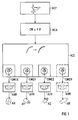
- FIG. 1 shows a block diagram of a numerical control, in which a predetermined numerical control program NCP, after a block preparation NCA in an interpolator NCI, determines setpoints for controlling the axes in interpolation steps.
- a predetermined numerical control program NCP after a block preparation NCA in an interpolator NCI, determines setpoints for controlling the axes in interpolation steps.
- Some of the axes X, Y, Z, R have a software limit switch SWEX, SWEY, SWEZ, SWER which limits the axis movements to a definable end position.
- the software limit switch SWER, the axis controller ARR and the axis drive AR are shown in dash-dotted lines in FIG. 1 to indicate that a software limit switch, an axis controller and an axis drive can be present for any number of axes.
- the software limit switches SWEX, SWEY, SWEZ, SWER check whether the axis drives AX, AY, AZ, AR are below Taking into account their axial speed to be achieved in the next interpolation step when braking with the respectively maximum permissible axial braking acceleration can come to a standstill up to the respective axial end position determined by the respective software limit switch.
- the setpoint for the next interpolation step is output to the corresponding axis controller AXR, AYR, AZR, ARR and the corresponding axis drives AX, AY, AZ, AR are thus controlled.
- a setpoint that corresponds to the respective maximum permissible axial braking acceleration is output to the corresponding axis controller instead of the setpoint for the next interpolation step.
- the corresponding axle drive is thus controlled so that the associated axle is braked with its respective maximum permissible axial braking acceleration.
- Such an axis is released from a possibly existing interpolation group and the remaining axes are additionally braked by the NCI interpolator with the machining path-specific brake acceleration.
- FIG. 2 and FIG. 3 and FIG. 5 and FIG. 6 the invention is explained using the X axis as an example. The same applies to all other axes with software limit switches.
- FIG. 4 and FIG. 7 show the solutions suitable for FIG. 2 and FIG. 3, or FIG. 5 and FIG. 6.
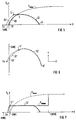
- FIG. 2, FIG. 5, FIG. 4 and FIG. 7 are diagrams with a horizontal coordinate X, which corresponds to the position along the X axis of the machine tool or the robot, and with a vertical one Coordinate Vx, which corresponds to the speed along this X axis.
- the point SWE corresponds to the end position of the axis movements along the X axis specified by the software limit switch SWEX.
- the curve Vxmax corresponds to the maximum speed along the X axis so that it can come to a standstill in time.
- the Vxmax curve arises from the fact that the maximum speed is calculated for each position along the X-axis, so that the X-axis with its corresponding inertia comes to a standstill exactly at the specified end position SWE if the maximum permissible for the X-axis axial braking acceleration is braked.
- the details of such calculations are part of normal specialist knowledge and do not need to be explained further.
- the point SWVE marks the additional software pre-limit switch of the previous solution.
- the axis drive is limited by a greatly reduced maximum speed Vxbmax.
- curve I1 represents an interpolation curve in the local velocity space X-Vx.
- the interpolation curve I1 is completely below the maximum velocity curve Vxmax. This means that when braking with the maximum permissible axial braking acceleration for the X axis, the X axis would always come to a standstill before the predetermined end position SWE.
- the interpolation curve I1 can therefore be processed unrestrained, at least as far as the X axis is concerned.
- FIG. 3 is a diagram with an interpolated trajectory in the XY space, which is represented by the X and Y axes of the machine tool or the robot is clamped.
- the limit line SWE corresponds to the end position of the axis movements in the X direction specified by the software limit switch SWEX.
- the interpolated circular path curve I1 'in XY space is created by an interpolation association of the X and Y axes.
- the X component of this interpolation group is shown in FIG. 1 as the interpolation curve I1 and, as far as the X axis is concerned, can be processed without being braked, although the interpolated path curve I1 'in the XY space comes very close to the limit line SWE of the software limit switch.
- the X component of this interpolation group is shown in FIG. 4 as an interpolation curve I1 ′′.
- this interpolation curve I1 ′′ is in the area between the software pre-limit switch SWVE and the actual software limit switch SWE and is therefore unnecessarily limited by the reduced maximum speed Vxbmax.
- the processing speed is reduced, although the interpolation curve I1 'is actually always below the maximum speed Vxmax that can still be braked (compare FIG. 4 with FIG. 2).
- the method according to the invention in FIG. 2 is thus a clear improvement over the known method in FIG. 4.
- the curve I2 represents an interpolation curve in the local velocity space X-Vx. From the first interpolation point i0 to the interpolation point i1, the interpolation curve I2 lies completely below the maximum speed curve Vxmax. This means that when braking with the maximum permissible axial braking acceleration for the X axis, the X axis would always come to a standstill before the predetermined end position SWE. For this reason, the interpolation curve I2 is also processed without braking from the first interpolation point i0 to the interpolation point i1. At the interpolation point i1, the interpolator NCI, like any other interpolation point, produces the next interpolation point - in this case point i2 - determined.
- the software limit switch SWEX determines that from point i2, braking with the maximum permissible axial braking acceleration for the X-axis along the dash-dotted braking curve B2 causes the X-axis to come to a standstill at point S2, i.e. only after the specified one SWE end position. This situation can also be seen graphically from the fact that point i2 lies beyond the Vxmax curve.
- the software limit switch SWEX therefore prevents the next interpolation point i2 from being output to the X axis as a setpoint and instead initiates an immediate deceleration starting from point i1 with the maximum permitted axial braking acceleration for the X axis along the dash-dotted braking curve B1 .
- the X axis therefore comes to a standstill at point S1, ie on or immediately before the predetermined end position SWE.
- FIG. 6 is a diagram with an interpolated trajectory in the XY space, which is spanned by the X and Y axes of the machine tool or the robot.
- the limit line SWE corresponds to the end position of the axis movements in the X direction specified by the software limit switch SWEX.
- the interpolated circular path curve I2 'in the XY space is created by an interpolation association of the X and Y axes.
- the X component of the interpolation group is shown in FIG. 5 as an interpolation curve I2 and, as far as the X axis is concerned, can be processed without braking down to point i1 '.
- the further interpolation is interrupted and braking of the X axis is initiated with the maximum permissible axial braking acceleration for the X axis, and is thus released from the interpolation association comprising only two axes in this example.
- the Y-axis remaining from the interpolation group is braked only with the machining path-specific brake acceleration.
- the machining path leaves the intended circular path I2 'and follows the dash-dotted braking curve B1' to a standstill at point S1 ', which is on or immediately before the predetermined end position SWE.
- the end position of the axis movements in the X direction specified by the software limit switch is not exceeded.
- the X component of the interpolation network is shown in FIG. 7 as an interpolation curve I2 ′′.
- this interpolation curve I2 '' is in the area between the software pre-limit switch SWVE and the actual software limit switch SWE and is therefore unnecessarily limited by the reduced maximum speed Vxbmax and the processing speed is therefore reduced.
- this is only recognized when the SWE end position limit specified by the software limit switch is reached at point i1 '' and emergency braking with braking acceleration that exceeds the maximum permissible axial braking accelerations is initiated so that the X axis is soon behind the SWE end position limit on Point Sx comes to a standstill.
- braking is not only carried out with excessive axial braking accelerations, but the limit position limit SWE cannot be maintained either.
Abstract
Description
Die Erfindung bezieht sich auf ein Verfahren zum Betrieb einer numerisch gesteuerten mehrachsigen Werkzeugmaschine oder eines Roboters gemäß einem jeweils vorgegebenen Programm, das nach einer Satzaufbereitung in einem Interpolator in Interpolationsschritten Sollwerte zur Ansteuerung der Achsen bestimmt, wobei mindestens eine der Achsen durch einen Software-Endschalter auf eine jeweils vorgebbare Endlage begrenzbar ist.The invention relates to a method for operating a numerically controlled multi-axis machine tool or a robot according to a respectively predetermined program, which, after block preparation in an interpolator, determines target values for controlling the axes in interpolation steps, at least one of the axes being switched on by a software limit switch a predeterminable end position can be limited.
Bei einer numerisch gesteuerten mehrachsigen Werkzeugmaschine oder einem Roboters sind die Achsantriebe üblicherweise mit hardwaremäßigen Endschaltern versehen. Zusätzlich können einige Achsen auch noch mit sogenannten Software-Endschaltern versehen sein, z.B. um dem Benutzer eine frei einstellbare Arbeitsfeldbegrenzung zu erlauben. Die Steuerung der Werkzeugmaschine oder des Roboters muß dann sicherstellen, daß die jeweiligen Achsantriebe diese zusätzlichen Software-Endschalter berücksichtigen bzw. daß verhindert wird, daß ein Achse beispielsweise während der Aufführung eines Teileprogramms über ihren vorgegebenen Software-Endschalter hinausfährt.In the case of a numerically controlled multi-axis machine tool or a robot, the axis drives are usually provided with hardware limit switches. In addition, some axes can also be equipped with so-called software limit switches, e.g. to allow the user a freely adjustable working area limitation. The control of the machine tool or the robot must then ensure that the respective axis drives take these additional software limit switches into account or that an axis is prevented from moving beyond its predetermined software limit switch, for example, during the execution of a part program.
Im Betrieb fahren die Achsantriebe mit einer bestimmten Geschwindigkeit und haben daher auch eine entsprechende Trägheit. Dazu kommt, daß die Achsantriebe nur mit einer bestimmten maximalen zulässigen Bremsbeschleunigung abgebremst werden können. Wenn erst bei Übertretung des Software-Endschalters abgebremst wird, entsteht das Problem, daß die Achse erst hinter der vorgegebenen Position des Software-Endschalters zum Stillstand kommt und zwar auch dann, wenn mit mehr als der maximalen zulässigen Bremsbeschleunigung der Achse abgebremst wird. Das Überfahren der vorgegebenen Position des Software-Endschalters ist selbstverständlich aus Sicherheitsgründen unerwünscht.In operation, the axle drives run at a certain speed and therefore have a corresponding inertia. In addition, the axle drives can only be braked with a certain maximum permissible braking acceleration. If the brake is not applied until the software limit switch is exceeded, the problem arises that the axis only comes to a standstill after the predetermined position of the software limit switch, even if the axis has more than the maximum permitted braking acceleration is braked. Passing over the predetermined position of the software limit switch is of course undesirable for safety reasons.
Die bisherige Lösung bestand darin, daß jeder Software-Endschalter mit einem zusätzlichen Software-Vor-Endschalter versehen wurde und daß im Bereich zwischen dem Software-Vor-Endschalter und dem eigentlichen Software-Endschalter der entsprechende Achsantrieb mit einer stark herabgesetzten Maximalgeschwindigkeit betrieben wurde. Eine herabgesetzte Maximalgeschwindigkeit bestimmt jedoch die Trägheit der Achse. Bei der Abbremsung wird jedoch dennoch die maximale zulässige Abbremsungsbeschleunigung überschritten, damit die Achse nicht allzuweit hinter der vorgegebenen Position des Software-Endschalters zum Stillstand kommt.The previous solution was that each software limit switch was provided with an additional software pre-limit switch and that in the area between the software pre-limit switch and the actual software limit switch the corresponding final drive was operated at a greatly reduced maximum speed. However, a reduced maximum speed determines the inertia of the axis. When braking, however, the maximum permissible braking acceleration is still exceeded so that the axis does not come to a standstill too far behind the predetermined position of the software limit switch.
Diese Lösung hat unter anderem den Nachteil, daß ein Achsantrieb, dessen Bearbeitungsbahn in den Bereich zwischen Software-Vor-Endschalter und dem eigentlichen Software-Endschalter eindringt, grundsätzlich mit der herabgesetzten Maximalgeschwindigkeit fährt, auch wenn der eigentlichen Software-Endschalter nie erreicht wird, weil vielleicht die Bearbeitungsbahn parallel zum Software-Endschalter verläuft. Ferner wird durch die herabgesenkte Maximalgeschwindigkeit das Problem nicht richtig gelöst, weil lediglich die Entfernung hinter der vorgegebenen Position des Software-Endschalters, wo die Achse letztendlich zum Stillstand kommen kann, nur begrenzt wird. Die vorgegebene Position des Software-Endschalters würde aber in jedem Fall überfahren. Auch das Abbremsen mit mehr als der maximalen zulässigen Bremsungsbeschleunigung wäre für den Achsantrieb schädlich.This solution has the disadvantage, among other things, that an axis drive, the machining path of which penetrates into the area between the software pre-limit switch and the actual software limit switch, generally runs at the reduced maximum speed, even if the actual software limit switch is never reached because maybe the machining path runs parallel to the software limit switch. Furthermore, the problem is not properly solved by the reduced maximum speed, because only the distance behind the predetermined position of the software limit switch, where the axis can ultimately come to a standstill, is only limited. The predefined position of the software limit switch would be exceeded in any case. Braking with more than the maximum permitted braking acceleration would also be detrimental to the axle drive.
Aufgabe der Erfindung ist es, ein Verfahren der eingangs genannten Art so auszubilden, daß eine Achse mit Software-Endschalter nicht hinter der vorgegebenen Position zum Stillstand kommt, daß die Maximalgeschwindigkeit der Achse nicht unnötigerweise herabgesetzt wird und daß nur mit der maximalen zulässigen Bremsungsbeschleunigung gebremst wird.The object of the invention is to develop a method of the type mentioned at the outset such that an axis with a software limit switch does not come to a standstill behind the predetermined position, and that the maximum speed of the axis does not is unnecessarily reduced and that braking is only carried out with the maximum permissible braking acceleration.
Gemäß der Erfindung wird diese Aufgabe dadurch gelöst, daß im Interpolator bei jedem Bestimmen des nächsten Interpolationsschritts für jede Achse mit Software-Endschalter geprüft wird, ob diese unter Berücksichtigung ihrer beim nächsten Interpolationsschritt zu erreichenden axialen Geschwindigkeit bei einer Bremsung mit ihrer maximalen axialen Bremsbeschleunigung noch bis zu der durch den jeweiligen Software-Endschalter bestimmten jeweiligen axialen Endlage zum Stehen kommen kann, und daß Achsen, für die dies nicht mehr der Fall ist, anstelle des nächsten Interpolationsschritts mit ihrer jeweiligen maximalen axialen Bremsbeschleunigung abgebremst werden.According to the invention, this object is achieved in that in the interpolator each time the next interpolation step is determined for each axis with a software limit switch, whether it takes into account the axial speed to be achieved in the next interpolation step during braking with its maximum axial braking acceleration can come to a standstill at the respective axial end position determined by the respective software limit switch, and that axles for which this is no longer the case are braked with their respective maximum axial braking acceleration instead of the next interpolation step.
Diese Erfindung hat den Vorteil, daß die vom Software-Endschalter vorgegebene Endlage keinesfalls überfahren wird, daß nur mit der maximal zulässigen axialen Bremsbeschleunigung abgebremst wird und daß die Bahngeschwindigkeit in der Nähe des Software-Endschalters nicht unnötigerweise begrenzt wird.This invention has the advantage that the end position specified by the software limit switch is never exceeded, that braking is only carried out with the maximum permissible axial braking acceleration and that the path speed in the vicinity of the software limit switch is not unnecessarily limited.
Eine vorteilhafte Weiterbildung der Erfindung besteht darin, daß dann, wenn eine Achse zur Endlagenbegrenzung mit ihren jeweiligen maximalen axialen Bremsbeschleunigungen abgebremst wird, diese Achse aus dem Interpolationsverband gelöst wird und die verbleibenden Achsen mit der bearbeitungsbahnspezifischen Bremsbeschleunigung abgebremst werden.An advantageous further development of the invention consists in that when an axis is braked to limit the end position with its respective maximum axial braking accelerations, this axis is released from the interpolation group and the remaining axes are braked with the machining path-specific braking acceleration.
Dies hat den Vorteil, daß nur die jeweils vom Software-Endschalter betroffenen Achse maximal abgebremst wird, während die verbleibenden Achsen mit der bearbeitungsbahnspezifischen Bremsbeschleunigung relativ sanft bremsen, damit Achsen mit geringeren zulässigen axialen Bremsbeschleunigungen nicht überlastet werden.This has the advantage that only the axis affected by the software limit switch is braked to a maximum, while the remaining axes brake relatively gently with the machining path-specific brake acceleration, so that axes with lower permissible axial brake accelerations are not overloaded.
Ein Ausführungsbeispiel der Erfindung ist in den Zeichnungen dargestellt und wird im folgenden näher erläutert. Dabei zeigen:
- FIG 1
- ein Blockdiagramm einer erfindungsgemäßen numerischen Steuerung,
- FIG 2 und 5
- Diagramme mit erfindungsgemäßen Interpolationskurven im Orts-Geschwindigkeitsraum,
- FIG 3 und 6
- Diagramme mit interpolierten Bahnverläufen im X-Y-Ortsraum,
- FIG 4 und 7
- Diagramme mit bekannten Interpolationskurven im Orts-Geschwindigkeitsraum.
- FIG. 1
- 2 shows a block diagram of a numerical control according to the invention,
- 2 and 5
- Diagrams with interpolation curves according to the invention in the spatial velocity space,
- 3 and 6
- Diagrams with interpolated trajectories in the XY space,
- 4 and 7
- Diagrams with known interpolation curves in the local velocity space.
Die Darstellung gemäß FIG 1 zeigt ein Blockdiagramm einer numerischen Steuerung, bei der ein vorgegebenes numerisches Steuerungsprogramm NCP, nach einer Satzaufbereitung NCA in einem Interpolator NCI in Interpolationsschritten Sollwerte zur Ansteuerung der Achsen bestimmt. Einige der Achsen X, Y, Z, R haben einen Software-Endschalter SWEX, SWEY, SWEZ, SWER der die Achsbewegungen auf eine jeweils vorgebbare Endlage begrenzt.The illustration according to FIG. 1 shows a block diagram of a numerical control, in which a predetermined numerical control program NCP, after a block preparation NCA in an interpolator NCI, determines setpoints for controlling the axes in interpolation steps. Some of the axes X, Y, Z, R have a software limit switch SWEX, SWEY, SWEZ, SWER which limits the axis movements to a definable end position.
Der Software-Endschalter SWER, der Achsregler ARR und der Achsantrieb AR sind strichpunktiert in FIG 1 gezeichnet, um anzudeuten, daß jeweils ein Software-Endschalter, ein Achsregler und ein Achsantrieb für beliebig viele Achsen vorhanden sein können.The software limit switch SWER, the axis controller ARR and the axis drive AR are shown in dash-dotted lines in FIG. 1 to indicate that a software limit switch, an axis controller and an axis drive can be present for any number of axes.
Nachdem der Interpolator bei dem jeweils nächsten Interpolationsschritt den Sollwert für jede Achse X, Y, Z, R, bestimmt hat, wird in den Software-Endschaltern SWEX, SWEY, SWEZ, SWER geprüft, ob die Achsantriebe AX, AY, AZ, AR unter Berücksichtigung ihrer beim nächsten Interpolationsschritt zu erreichenden axialen Geschwindigkeit bei einer Bremsung mit der jeweils maximalen zulässigen axialen Bremsbeschleunigung noch bis zu der durch den jeweiligen Software-Endschalter bestimmten jeweiligen axialen Endlage zum Stillstand kommen können.After the interpolator has determined the setpoint for each axis X, Y, Z, R, in the next interpolation step, the software limit switches SWEX, SWEY, SWEZ, SWER check whether the axis drives AX, AY, AZ, AR are below Taking into account their axial speed to be achieved in the next interpolation step when braking with the respectively maximum permissible axial braking acceleration can come to a standstill up to the respective axial end position determined by the respective software limit switch.
Wenn eine Achse noch vor dem jeweiligen Software-Endschalter zum Stillstand gebracht werden kann, wird der Sollwert für den nächsten Interpolationsschritt an den entsprechenden Achsregler AXR, AYR, AZR, ARR ausgegeben und die entsprechenden Achsantriebe AX, AY, AZ, AR werden damit angesteuert.If an axis can be brought to a standstill before the respective software limit switch, the setpoint for the next interpolation step is output to the corresponding axis controller AXR, AYR, AZR, ARR and the corresponding axis drives AX, AY, AZ, AR are thus controlled.
Bei Achsen, die nicht mehr vor dem jeweiligen Software-Endschalter zum Stillstand gebracht werden können, wird anstelle des Sollwertes für den nächsten Interpolationsschritt ein Sollwert, der der jeweiligen maximalen zulässigen axialen Bremsbeschleunigung entspricht, an den entsprechenden Achsregler ausgegeben. Der entsprechende Achsantrieb wird damit so gesteuert, daß die zugehörige Achse mit ihrer jeweiligen maximalen zulässigen axialen Bremsbeschleunigung abgebremst wird.For axes that can no longer be brought to a standstill in front of the respective software limit switch, a setpoint that corresponds to the respective maximum permissible axial braking acceleration is output to the corresponding axis controller instead of the setpoint for the next interpolation step. The corresponding axle drive is thus controlled so that the associated axle is braked with its respective maximum permissible axial braking acceleration.
Eine solche Achse wird dabei aus einem eventuell bestehenden Interpolationsverband gelöst und die verbleibenden Achsen werden zusätzlich durch den Interpolator NCI mit der bearbeitungsbahnspezifischen Bremsbeschleunigung ebenfalls abgebremst.Such an axis is released from a possibly existing interpolation group and the remaining axes are additionally braked by the NCI interpolator with the machining path-specific brake acceleration.
In FIG 2 und FIG 3 und FIG 5 und FIG 6 wird die Erfindung beispielhaft an Hand der X-Achse erklärt. Entsprechendes gilt für alle anderen Achsen mit Software-Endschalter. FIG 4 und FIG 7 zeigen die zu FIG 2 und FIG 3, bzw. FIG 5 und FIG 6 passenden Lösungen.In FIG. 2 and FIG. 3 and FIG. 5 and FIG. 6, the invention is explained using the X axis as an example. The same applies to all other axes with software limit switches. FIG. 4 and FIG. 7 show the solutions suitable for FIG. 2 and FIG. 3, or FIG. 5 and FIG. 6.
FIG 2, FIG 5, FIG 4 und FIG 7 sind Diagramme mit waagerechter Koordinate X, die der Position entlang der X-Achse der Werkzeugmaschine oder des Roboters entspricht, und mit senkrechter Koordinate Vx, die der Geschwindigkeit entlang dieser X-Achse entspricht.FIG. 2, FIG. 5, FIG. 4 and FIG. 7 are diagrams with a horizontal coordinate X, which corresponds to the position along the X axis of the machine tool or the robot, and with a vertical one Coordinate Vx, which corresponds to the speed along this X axis.
Der Punkt SWE entspricht der durch den Software-Endschalter SWEX vom Benutzer vorgegebenen Endlage der Achsbewegungen längs der X-Achse.The point SWE corresponds to the end position of the axis movements along the X axis specified by the software limit switch SWEX.
Die Kurve Vxmax entspricht der maximalen Geschwindigkeit entlang der X-Achse, damit diese noch rechtzeitig zum Stillstand kommen kann. Die Vxmax Kurve entsteht dadurch, daß für jede Lage entlang der X-Achse die maximale Geschwindigkeit berechnet wird, damit die X-Achse mit ihrer entsprechenden Trägheit genau auf der vorgegebenen Endlage SWE zu Stillstand kommt, wenn mit der für die X-Achse maximalen zulässigen axialen Bremsbeschleunigung abgebremst wird. Die Einzelheiten derartige Berechnungen gehören zum normalen Fachwissen und brauchen nicht weiter erläutert zu werden.The curve Vxmax corresponds to the maximum speed along the X axis so that it can come to a standstill in time. The Vxmax curve arises from the fact that the maximum speed is calculated for each position along the X-axis, so that the X-axis with its corresponding inertia comes to a standstill exactly at the specified end position SWE if the maximum permissible for the X-axis axial braking acceleration is braked. The details of such calculations are part of normal specialist knowledge and do not need to be explained further.
In FIG 4 und 7 markiert der Punkt SWVE den zusätzlichen Software-Vor-Endschalter der bisherigen Lösung. In dem Bereich zwischen dem Software-Vor-Endschalter SWVE und dem eigentlichen Software-Endschalter SWE ist der Achsantrieb durch eine stark herabgesetzte Maximalgeschwindigkeit Vxbmax begrenzt.In FIGS. 4 and 7, the point SWVE marks the additional software pre-limit switch of the previous solution. In the area between the software limit switch SWVE and the actual software limit switch SWE, the axis drive is limited by a greatly reduced maximum speed Vxbmax.
In FIG 2 stellt die Kurve I1 eine Interpolationskurve im Orts-Geschwindigkeitsraum X-Vx dar. Die Interpolationskurve I1 liegt vollständig unterhalb der maximalen Geschwindigkeitskurve Vxmax. Das bedeutet, daß bei einer Abbremsung mit der für die X-Achse maximalen zulässigen axialen Bremsbeschleunigung die X-Achse immer vor der vorgegebenen Endlage SWE zum Stillstand kommen würde. Die Interpolationskurve I1 kann daher, zumindest was die X-Achse angeht, ungebremst abgearbeitet werden.In FIG. 2, curve I1 represents an interpolation curve in the local velocity space X-Vx. The interpolation curve I1 is completely below the maximum velocity curve Vxmax. This means that when braking with the maximum permissible axial braking acceleration for the X axis, the X axis would always come to a standstill before the predetermined end position SWE. The interpolation curve I1 can therefore be processed unrestrained, at least as far as the X axis is concerned.
FIG 3 ist ein Diagramm mit einer interpolierten Bahnkurve im X-Y Ortsraum, der durch die X und Y-Achsen der Werkzeugmaschine oder des Roboters aufgespannt wird. Die Grenzlinie SWE entspricht der durch den Software-Endschalter SWEX vom Benutzer vorgegebenen Endlage der Achsbewegungen in der X-Richtung. Die interpolierte Kreisbahnkurve I1' im X-Y Raum entsteht durch einen Interpolationsverband der X- und Y-Achsen. Der X-Anteil dieses Interpolationsverbands ist in FIG 1 als Interpolationskurve I1 dargestellt und kann, was die X-Achse angeht, ungebremst abgearbeitet werden, obgleich die interpolierte Bahnkurve I1' im X-Y Raum der Grenzlinie SWE des Software-Endschalters sehr nahe kommt.3 is a diagram with an interpolated trajectory in the XY space, which is represented by the X and Y axes of the machine tool or the robot is clamped. The limit line SWE corresponds to the end position of the axis movements in the X direction specified by the software limit switch SWEX. The interpolated circular path curve I1 'in XY space is created by an interpolation association of the X and Y axes. The X component of this interpolation group is shown in FIG. 1 as the interpolation curve I1 and, as far as the X axis is concerned, can be processed without being braked, although the interpolated path curve I1 'in the XY space comes very close to the limit line SWE of the software limit switch.
Bei der bekannten Lösung wird der X-Anteil dieses Interpolationsverbands in FIG 4 als Interpolationskurve I1'' dargestellt. Diese Interpolationskurve I1'' befindet sich aber in dem Bereich zwischen dem Software-Vor-Endschalter SWVE und dem eigentlichen Software-Endschalter SWE und wird deshalb durch die herabgesetzte Maximalgeschwindigkeit Vxbmax unnötigerweise begrenzt. Die Bearbeitungsgeschwindigkeit ist herabgesetzt, obgleich die Interpolationskurve I1' eigentlich immer unterhalb der noch abbremsbaren maximalen Geschwindigkeit Vxmax liegt (vergleiche FIG 4 mit FIG 2). Das erfindungsgemäße Verfahren der FIG 2 ist somit eine eindeutige Verbesserung gegenüber dem bekannten Verfahren der FIG 4.In the known solution, the X component of this interpolation group is shown in FIG. 4 as an interpolation curve I1 ″. However, this interpolation curve I1 ″ is in the area between the software pre-limit switch SWVE and the actual software limit switch SWE and is therefore unnecessarily limited by the reduced maximum speed Vxbmax. The processing speed is reduced, although the interpolation curve I1 'is actually always below the maximum speed Vxmax that can still be braked (compare FIG. 4 with FIG. 2). The method according to the invention in FIG. 2 is thus a clear improvement over the known method in FIG. 4.
In FIG 5 stellt die Kurve I2 eine Interpolationskurve im Orts-Geschwindigkeitsraum X-Vx dar. Vom ersten Interpolationspunkt i0 bis zum Interpolationspunkt i1 liegt die Interpolationskurve I2 vollständig unterhalb der maximalen Geschwindigkeitskurve Vxmax. Das bedeutet, daß bei einer Abbremsung mit der für die X-Achse maximalen zulässigen axialen Bremsbeschleunigung die X-Achse immer vor der vorgegebenen Endlage SWE zum Stillstand kommen würde. Die Interpolationskurve I2 wird aus diesem Grunde vom ersten Interpolationspunkt i0 bis zum Interpolationspunkt i1 auch ungebremst abgearbeitet. Am Interpolationspunkt i1 wird vom Interpolator NCI, wie bei jedem anderen Interpolationspunkt auch, der nächste Interpolationspunkt - in diesem Fall der Punkt i2 - ermittelt. Der Software-Endschalter SWEX stellt fest, daß vom Punkt i2 aus eine Abbremsung mit der für die X-Achse maximalen zulässigen axialen Bremsbeschleunigung entlang der strichpunktierten Bremskurve B2 bewirkt, daß die X-Achse am Punkt S2 zum Stillstand käme, also erst hinter der vorgegebenen Endlage SWE. Diese Situation ist auch graphisch daran zu erkennen, daß der Punkt i2 jenseits der Vxmax Kurve liegt. Der Software-Endschalter SWEX verhindert daher, daß der nächste Interpolationspunkt i2 als Sollwert an die X-Achse ausgegeben wird und leitet statt dessen eine vom Punkt i1 ausgehende sofortige Abbremsung mit der für die X-Achse maximalen zulässigen axialen Bremsbeschleunigung entlang der strichpunktierten Bremskurve B1 ein. Die X-Achse kommt daher schon am Punkt S1 zum Stillstand, d.h. auf oder unmittelbar vor der vorgegebenen Endlage SWE.5, the curve I2 represents an interpolation curve in the local velocity space X-Vx. From the first interpolation point i0 to the interpolation point i1, the interpolation curve I2 lies completely below the maximum speed curve Vxmax. This means that when braking with the maximum permissible axial braking acceleration for the X axis, the X axis would always come to a standstill before the predetermined end position SWE. For this reason, the interpolation curve I2 is also processed without braking from the first interpolation point i0 to the interpolation point i1. At the interpolation point i1, the interpolator NCI, like any other interpolation point, produces the next interpolation point - in this case point i2 - determined. The software limit switch SWEX determines that from point i2, braking with the maximum permissible axial braking acceleration for the X-axis along the dash-dotted braking curve B2 causes the X-axis to come to a standstill at point S2, i.e. only after the specified one SWE end position. This situation can also be seen graphically from the fact that point i2 lies beyond the Vxmax curve. The software limit switch SWEX therefore prevents the next interpolation point i2 from being output to the X axis as a setpoint and instead initiates an immediate deceleration starting from point i1 with the maximum permitted axial braking acceleration for the X axis along the dash-dotted braking curve B1 . The X axis therefore comes to a standstill at point S1, ie on or immediately before the predetermined end position SWE.
FIG 6 ist ein Diagramm mit einer interpolierten Bahnkurve im X-Y Ortsraum, der durch die X und Y-Achsen der Werkzeugmaschine oder des Roboters aufgespannt wird. Die Grenzlinie SWE entspricht der durch den Software-Endschalter SWEX vom Benutzer vorgegebenen Endlage der Achsbewegungen in der X-Richtung. Die interpolierte Kreisbahnkurve I2' im X-Y Raum entsteht durch einen Interpolationsverband der X- und Y-Achsen. Der X-Anteil des Interpolationsverbands ist in FIG 5 als Interpolationskurve I2 dargestellt und kann, was die X-Achse angeht, bis zum Punkt i1' ungebremst abgearbeitet werden. Am Punkt i1' wird die weitere Interpolation unterbrochen und eine Abbremsung X-Achse mit der für die X-Achse maximalen zulässigen axialen Bremsbeschleunigung eingeleitet und damit aus dem in diesem Beispiel nur zwei Achsen umfassenden Interpolationsverbands gelöst. Die aus dem Interpolationsverband verbleibende Y-Achse wird nur mit der bearbeitungsbahnspezifischen Bremsbeschleunigung abgebremst. In Folge davon, verläßt die Bearbeitungsbahn die vorgesehene Kreisbahn I2' und folgt der strichpunktierten Bremskurve B1' bis zum Stillstand am Punkt S1', der auf oder unmittelbar vor der vorgegebenen Endlage SWE liegt. Die von dem Software-Endschalter vorgegebene Endlage der Achsbewegungen in der X-Richtung wird nicht überfahren.6 is a diagram with an interpolated trajectory in the XY space, which is spanned by the X and Y axes of the machine tool or the robot. The limit line SWE corresponds to the end position of the axis movements in the X direction specified by the software limit switch SWEX. The interpolated circular path curve I2 'in the XY space is created by an interpolation association of the X and Y axes. The X component of the interpolation group is shown in FIG. 5 as an interpolation curve I2 and, as far as the X axis is concerned, can be processed without braking down to point i1 '. At point i1 ', the further interpolation is interrupted and braking of the X axis is initiated with the maximum permissible axial braking acceleration for the X axis, and is thus released from the interpolation association comprising only two axes in this example. The Y-axis remaining from the interpolation group is braked only with the machining path-specific brake acceleration. As a result, the machining path leaves the intended circular path I2 'and follows the dash-dotted braking curve B1' to a standstill at point S1 ', which is on or immediately before the predetermined end position SWE. The end position of the axis movements in the X direction specified by the software limit switch is not exceeded.
Bei der bekannten Lösung wird der X-Anteil des Interpolationsverbands in FIG 7 als Interpolationskurve I2'' dargestellt. Diese Interpolationskurve I2'' befindet sich aber in dem Bereich zwischen dem Software-Vor-Endschalter SWVE und dem eigentlichen Software-Endschalter SWE und wird deshalb durch die herabgesetzte Maximalgeschwindigkeit Vxbmax unnötigerweise begrenzt und die Bearbeitungsgeschwindigkeit ist daher herabgesetzt. Zudem wird erst beim Erreichen der von dem Software-Endschalter vorgegebene Endlagenbegrenzung SWE am Punkt i1'' dies erkannt und eine Notbremsung mit einer Bremsbeschleunigung, die die maximale zulässige axiale Bremsbeschleunigungen übersteigt, eingeleitet, damit die X-Achse möglichst bald hinter der Endlagenbegrenzung SWE am Punkt Sx zum Stillstand kommt. Bei der bekannten Lösung wird nicht nur mit zu großen axialen Bremsbeschleunigungen abgebremst, sondern die Endlagenbegrenzung SWE kann auch nicht eingehalten werden.In the known solution, the X component of the interpolation network is shown in FIG. 7 as an interpolation curve I2 ″. However, this interpolation curve I2 '' is in the area between the software pre-limit switch SWVE and the actual software limit switch SWE and is therefore unnecessarily limited by the reduced maximum speed Vxbmax and the processing speed is therefore reduced. In addition, this is only recognized when the SWE end position limit specified by the software limit switch is reached at point i1 '' and emergency braking with braking acceleration that exceeds the maximum permissible axial braking accelerations is initiated so that the X axis is soon behind the SWE end position limit on Point Sx comes to a standstill. In the known solution, braking is not only carried out with excessive axial braking accelerations, but the limit position limit SWE cannot be maintained either.
Claims (2)
Applications Claiming Priority (2)
| Application Number | Priority Date | Filing Date | Title |
|---|---|---|---|
| DE19517771 | 1995-05-15 | ||
| DE19517771A DE19517771A1 (en) | 1995-05-15 | 1995-05-15 | Method for operating a numerically controlled machine tool or a robot |
Publications (3)
| Publication Number | Publication Date |
|---|---|
| EP0743579A2 true EP0743579A2 (en) | 1996-11-20 |
| EP0743579A3 EP0743579A3 (en) | 1997-04-23 |
| EP0743579B1 EP0743579B1 (en) | 1998-11-25 |
Family
ID=7761933
Family Applications (1)
| Application Number | Title | Priority Date | Filing Date |
|---|---|---|---|
| EP96106924A Expired - Lifetime EP0743579B1 (en) | 1995-05-15 | 1996-05-02 | Process for the operation of a numeric controlled machine tool or of a robot |
Country Status (3)
| Country | Link |
|---|---|
| EP (1) | EP0743579B1 (en) |
| AT (1) | ATE173841T1 (en) |
| DE (2) | DE19517771A1 (en) |
Cited By (4)
| Publication number | Priority date | Publication date | Assignee | Title |
|---|---|---|---|---|
| EP1901150A1 (en) * | 2006-09-14 | 2008-03-19 | Abb Research Ltd. | A method and device for avoiding collisions between an industrial robot and an object |
| WO2008151810A1 (en) * | 2007-06-14 | 2008-12-18 | Trumpf Werkzeugmaschinen Gmbh + Co. Kg | Method for the optimised movement co-ordination of measuring machines or machine-tools comprising redundant axles having a translatory action |
| EP2072195A1 (en) * | 2007-12-19 | 2009-06-24 | KUKA Roboter GmbH | Method for controlling the movement of a robot within a work room |
| DE10338792B4 (en) * | 2003-08-23 | 2009-12-24 | Steuerungstechnik Bbh Gmbh | Method and system for monitoring the emergency stop function in drives |
Families Citing this family (6)
| Publication number | Priority date | Publication date | Assignee | Title |
|---|---|---|---|---|
| DE10125445A1 (en) | 2001-05-25 | 2002-12-05 | Kuka Roboter Gmbh | Method for controlling the movement of a robot |
| US6678582B2 (en) | 2002-05-30 | 2004-01-13 | Kuka Roboter Gmbh | Method and control device for avoiding collisions between cooperating robots |
| DE10226140A1 (en) * | 2002-06-13 | 2004-01-08 | Kuka Roboter Gmbh | Method, for preventing collisions between industrial robots and other objects, involves checking predicted path configuration by distance/obstruction algorithms, stopping robot/other objects if collision impending |
| DE10226853B3 (en) * | 2002-06-15 | 2004-02-19 | Kuka Roboter Gmbh | Method for limiting the force of a robot part |
| DE102005010089B4 (en) * | 2005-03-04 | 2007-08-30 | Siemens Ag | Method and device for positioning an element of a machine |
| DE102019125326B3 (en) * | 2019-09-20 | 2020-12-03 | Franka Emika Gmbh | Predicted braking range of a robot manipulator |
Citations (1)
| Publication number | Priority date | Publication date | Assignee | Title |
|---|---|---|---|---|
| EP0583487A1 (en) * | 1992-07-21 | 1994-02-23 | Siemens Aktiengesellschaft | Method to acquire a time-optimal braking action for the axes drives of numerically controlled machines |
-
1995
- 1995-05-15 DE DE19517771A patent/DE19517771A1/en not_active Withdrawn
-
1996
- 1996-05-02 DE DE59600856T patent/DE59600856D1/en not_active Expired - Fee Related
- 1996-05-02 EP EP96106924A patent/EP0743579B1/en not_active Expired - Lifetime
- 1996-05-02 AT AT96106924T patent/ATE173841T1/en not_active IP Right Cessation
Patent Citations (1)
| Publication number | Priority date | Publication date | Assignee | Title |
|---|---|---|---|---|
| EP0583487A1 (en) * | 1992-07-21 | 1994-02-23 | Siemens Aktiengesellschaft | Method to acquire a time-optimal braking action for the axes drives of numerically controlled machines |
Cited By (6)
| Publication number | Priority date | Publication date | Assignee | Title |
|---|---|---|---|---|
| DE10338792B4 (en) * | 2003-08-23 | 2009-12-24 | Steuerungstechnik Bbh Gmbh | Method and system for monitoring the emergency stop function in drives |
| EP1901150A1 (en) * | 2006-09-14 | 2008-03-19 | Abb Research Ltd. | A method and device for avoiding collisions between an industrial robot and an object |
| WO2008031664A1 (en) * | 2006-09-14 | 2008-03-20 | Abb Research Ltd. | A method and a device for avoiding collisions between an industrial robot and an object |
| CN101512453B (en) * | 2006-09-14 | 2011-11-02 | Abb研究有限公司 | A method and device for avoiding collisions between an industrial robot and an object |
| WO2008151810A1 (en) * | 2007-06-14 | 2008-12-18 | Trumpf Werkzeugmaschinen Gmbh + Co. Kg | Method for the optimised movement co-ordination of measuring machines or machine-tools comprising redundant axles having a translatory action |
| EP2072195A1 (en) * | 2007-12-19 | 2009-06-24 | KUKA Roboter GmbH | Method for controlling the movement of a robot within a work room |
Also Published As
| Publication number | Publication date |
|---|---|
| ATE173841T1 (en) | 1998-12-15 |
| EP0743579B1 (en) | 1998-11-25 |
| EP0743579A3 (en) | 1997-04-23 |
| DE59600856D1 (en) | 1999-01-07 |
| DE19517771A1 (en) | 1996-11-21 |
Similar Documents
| Publication | Publication Date | Title |
|---|---|---|
| EP3202612B1 (en) | Method for operating a conveying device in the form of a long stator linear motor | |
| EP1963935B1 (en) | Method for the determination of a rough trajectory to be followed in a positionally guided manner | |
| EP2008752B1 (en) | Machine for machining workpieces and method for machine processing of workpieces | |
| EP1906281B1 (en) | Method and system for designing and verifying safety areas of an industrial robot | |
| DE4019516C2 (en) | Method for operating an industrial robot device and industrial robot device | |
| EP1789861B1 (en) | Method for avoiding collisions | |
| DE3408551C2 (en) | ||
| EP0743579B1 (en) | Process for the operation of a numeric controlled machine tool or of a robot | |
| DE3922524A1 (en) | METHOD FOR CONTROLLING THE MOVEMENTS OF AN AXIS ON PROGRAM-CONTROLLED MACHINES AND CONTROL SYSTEM | |
| DE3809630C1 (en) | ||
| EP3220223A1 (en) | Method for machining a workpiece in a machine tool with optimized processing time | |
| EP3037221A2 (en) | Method and manipulator assembly for conditional stopping of at least one manipulator on a sheet | |
| EP3818420B1 (en) | Time-optimized guidance of movement between rail sections | |
| EP1977295B1 (en) | Shaft regulation method | |
| EP2192465A1 (en) | Control of a follow-on drive with dynamic calculation of the dynamic of a leading axis | |
| EP0583487B1 (en) | Method to acquire a time-optimal braking action for the axes drives of numerically controlled machines | |
| EP4147102A1 (en) | Operating an at least two-axle machine tool | |
| EP0340538B2 (en) | Method for controlling the movement of a machine element | |
| EP2135143B1 (en) | Method and device for guiding the movement of a movable machine element of a numerically controlled machine | |
| EP0791193A1 (en) | Speed control for any override range effective over a plurality of blocks | |
| DE102015012111A1 (en) | Method for operating a plurality of robots of a production plant | |
| EP3689555A1 (en) | Force-limited method of at least one element of a production machine in manual operation | |
| EP3792716B1 (en) | Numerical control with buffering of load setpoints | |
| EP3309635A1 (en) | Determination of a sub-program optimised for each working machine | |
| WO2001033304A2 (en) | Control system for electric drive mechanisms and method for controlling a trajectory |
Legal Events
| Date | Code | Title | Description |
|---|---|---|---|
| PUAI | Public reference made under article 153(3) epc to a published international application that has entered the european phase |
Free format text: ORIGINAL CODE: 0009012 |
|
| AK | Designated contracting states |
Kind code of ref document: A2 Designated state(s): AT CH DE ES FR GB IT LI SE |
|
| PUAL | Search report despatched |
Free format text: ORIGINAL CODE: 0009013 |
|
| AK | Designated contracting states |
Kind code of ref document: A3 Designated state(s): AT CH DE ES FR GB IT LI SE |
|
| 17P | Request for examination filed |
Effective date: 19970604 |
|
| GRAG | Despatch of communication of intention to grant |
Free format text: ORIGINAL CODE: EPIDOS AGRA |
|
| 17Q | First examination report despatched |
Effective date: 19980115 |
|
| GRAG | Despatch of communication of intention to grant |
Free format text: ORIGINAL CODE: EPIDOS AGRA |
|
| GRAH | Despatch of communication of intention to grant a patent |
Free format text: ORIGINAL CODE: EPIDOS IGRA |
|
| GRAH | Despatch of communication of intention to grant a patent |
Free format text: ORIGINAL CODE: EPIDOS IGRA |
|
| GRAA | (expected) grant |
Free format text: ORIGINAL CODE: 0009210 |
|
| AK | Designated contracting states |
Kind code of ref document: B1 Designated state(s): AT CH DE ES FR GB IT LI SE |
|
| PG25 | Lapsed in a contracting state [announced via postgrant information from national office to epo] |
Ref country code: SE Free format text: THE PATENT HAS BEEN ANNULLED BY A DECISION OF A NATIONAL AUTHORITY Effective date: 19981125 Ref country code: IT Free format text: LAPSE BECAUSE OF FAILURE TO SUBMIT A TRANSLATION OF THE DESCRIPTION OR TO PAY THE FEE WITHIN THE PRESCRIBED TIME-LIMIT;WARNING: LAPSES OF ITALIAN PATENTS WITH EFFECTIVE DATE BEFORE 2007 MAY HAVE OCCURRED AT ANY TIME BEFORE 2007. THE CORRECT EFFECTIVE DATE MAY BE DIFFERENT FROM THE ONE RECORDED. Effective date: 19981125 Ref country code: GB Free format text: LAPSE BECAUSE OF NON-PAYMENT OF DUE FEES Effective date: 19981125 Ref country code: FR Free format text: LAPSE BECAUSE OF FAILURE TO SUBMIT A TRANSLATION OF THE DESCRIPTION OR TO PAY THE FEE WITHIN THE PRESCRIBED TIME-LIMIT Effective date: 19981125 Ref country code: ES Free format text: THE PATENT HAS BEEN ANNULLED BY A DECISION OF A NATIONAL AUTHORITY Effective date: 19981125 |
|
| REF | Corresponds to: |
Ref document number: 173841 Country of ref document: AT Date of ref document: 19981215 Kind code of ref document: T |
|
| REG | Reference to a national code |
Ref country code: CH Ref legal event code: EP |
|
| REF | Corresponds to: |
Ref document number: 59600856 Country of ref document: DE Date of ref document: 19990107 |
|
| EN | Fr: translation not filed | ||
| PG25 | Lapsed in a contracting state [announced via postgrant information from national office to epo] |
Ref country code: AT Free format text: LAPSE BECAUSE OF NON-PAYMENT OF DUE FEES Effective date: 19990502 |
|
| GBV | Gb: ep patent (uk) treated as always having been void in accordance with gb section 77(7)/1977 [no translation filed] |
Effective date: 19981125 |
|
| PLBE | No opposition filed within time limit |
Free format text: ORIGINAL CODE: 0009261 |
|
| STAA | Information on the status of an ep patent application or granted ep patent |
Free format text: STATUS: NO OPPOSITION FILED WITHIN TIME LIMIT |
|
| 26N | No opposition filed | ||
| PG25 | Lapsed in a contracting state [announced via postgrant information from national office to epo] |
Ref country code: LI Free format text: LAPSE BECAUSE OF NON-PAYMENT OF DUE FEES Effective date: 20000531 Ref country code: CH Free format text: LAPSE BECAUSE OF NON-PAYMENT OF DUE FEES Effective date: 20000531 |
|
| PGFP | Annual fee paid to national office [announced via postgrant information from national office to epo] |
Ref country code: DE Payment date: 20000717 Year of fee payment: 5 |
|
| REG | Reference to a national code |
Ref country code: CH Ref legal event code: PL |
|
| PG25 | Lapsed in a contracting state [announced via postgrant information from national office to epo] |
Ref country code: DE Free format text: LAPSE BECAUSE OF NON-PAYMENT OF DUE FEES Effective date: 20020301 |