EP2515079A2 - Système de navigation et procédé de commande de navigation d'un véhicule - Google Patents
Système de navigation et procédé de commande de navigation d'un véhicule Download PDFInfo
- Publication number
- EP2515079A2 EP2515079A2 EP11734835A EP11734835A EP2515079A2 EP 2515079 A2 EP2515079 A2 EP 2515079A2 EP 11734835 A EP11734835 A EP 11734835A EP 11734835 A EP11734835 A EP 11734835A EP 2515079 A2 EP2515079 A2 EP 2515079A2
- Authority
- EP
- European Patent Office
- Prior art keywords
- data
- image data
- vehicle
- navigation system
- place
- Prior art date
- Legal status (The legal status is an assumption and is not a legal conclusion. Google has not performed a legal analysis and makes no representation as to the accuracy of the status listed.)
- Granted
Links
Images


Classifications
-
- G—PHYSICS
- G01—MEASURING; TESTING
- G01C—MEASURING DISTANCES, LEVELS OR BEARINGS; SURVEYING; NAVIGATION; GYROSCOPIC INSTRUMENTS; PHOTOGRAMMETRY OR VIDEOGRAMMETRY
- G01C21/00—Navigation; Navigational instruments not provided for in groups G01C1/00 - G01C19/00
- G01C21/26—Navigation; Navigational instruments not provided for in groups G01C1/00 - G01C19/00 specially adapted for navigation in a road network
-
- B—PERFORMING OPERATIONS; TRANSPORTING
- B62—LAND VEHICLES FOR TRAVELLING OTHERWISE THAN ON RAILS
- B62D—MOTOR VEHICLES; TRAILERS
- B62D41/00—Fittings for identifying vehicles in case of collision; Fittings for marking or recording collision areas
-
- G—PHYSICS
- G07—CHECKING-DEVICES
- G07C—TIME OR ATTENDANCE REGISTERS; REGISTERING OR INDICATING THE WORKING OF MACHINES; GENERATING RANDOM NUMBERS; VOTING OR LOTTERY APPARATUS; ARRANGEMENTS, SYSTEMS OR APPARATUS FOR CHECKING NOT PROVIDED FOR ELSEWHERE
- G07C5/00—Registering or indicating the working of vehicles
- G07C5/08—Registering or indicating performance data other than driving, working, idle, or waiting time, with or without registering driving, working, idle or waiting time
- G07C5/0841—Registering performance data
- G07C5/085—Registering performance data using electronic data carriers
-
- G—PHYSICS
- G08—SIGNALLING
- G08G—TRAFFIC CONTROL SYSTEMS
- G08G1/00—Traffic control systems for road vehicles
- G08G1/09—Arrangements for giving variable traffic instructions
- G08G1/0962—Arrangements for giving variable traffic instructions having an indicator mounted inside the vehicle, e.g. giving voice messages
- G08G1/09626—Arrangements for giving variable traffic instructions having an indicator mounted inside the vehicle, e.g. giving voice messages where the origin of the information is within the own vehicle, e.g. a local storage device, digital map
Definitions
- the present invention relates to a navigation system and, more particularly, to a vehicle navigation system and a vehicle black box.
- LBS location based service
- a vehicle navigation service which measures a current location of a vehicle or guides a route to a destination is also rapidly activated.
- a vehicle black box capable of providing the objective data is used.
- a conventional vehicle black box provides only simple and superficial information about a vehicle state and cannot effectively meet the demands of users.
- An object of the present invention is to provide a navigation system which maps image data with location data and stores the mapped data, and a method for controlling a vehicle navigation system.
- a vehicle navigation system includes: a storage for storing map data; a communication unit for receiving, from a vehicle black box installed in a vehicle, image data captured by the block box and obtaining current location data of the vehicle; and a controller for acquiring place data from the map data using the current location data, mapping the received image data with the place data and storing the mapped data in the storage.
- a vehicle navigation system includes: a storage for storing map data; a communication unit for receiving image data mapped with location data from a black box installed in a vehicle; and a controller for obtaining place data from the map data using the location data mapped with the received image data, mapping the received image data with the place data and storing the mapped data in the storage.
- a vehicle navigation system includes: a storage for storing map data; a communication unit for transmitting location data to a black box installed in a vehicle and receiving image data mapped with the location data from the vehicle black box; and a controller for obtaining place data from the map data using the location data mapped with the received image data, mapping the received image data with the place data and storing the mapped data in the storage.
- a vehicle navigation system includes: a storage for storing map data; a communication unit for obtaining location data; and a controller for obtaining place data from the map data using the location data, transmitting the place data to a black box installed in a vehicle through the communication unit, receiving image data mapped with the location data from the vehicle black box through the communication unit, and storing the received image data in the storage.
- a method for controlling a vehicle navigation system includes: receiving, from a vehicle black box installed in a vehicle, image data captured by the block box in real time; obtaining current location data of the vehicle; acquiring place data from the map data using the current location data; mapping the received image data with the place data and storing the mapped data.
- a computer readable medium stores a program for executing one of the above-mentioned methods.
- the navigation system and a method for controlling a vehicle navigation system map image data obtained by a vehicle black box with location data and stores the mapped data, and thus a user can easily search relevant image data or image frame using location data and use the data to determine the cause of an accident and the negligence or fault in the event of a car accident.
- FIG. 1 illustrates a navigation system according to an embodiment of the present invention
- FIG. 2 illustrates a navigation system according to another embodiment of the present invention
- FIG. 3 is a block diagram of a vehicle navigation system shown in FIG. 1 ;
- FIG. 4 is a block diagram of a vehicle block box shown in FIG. 1 ;
- FIG. 5 illustrates a configuration of a communication network including the navigation system shown in FIG. 1 ;
- FIGS. 6 to 9 are flowcharts illustrating a procedure of mapping image data with location data according to an embodiment of the present invention.
- FIG. 10 shows an example of an image data list according to an embodiment of the present invention.
- FIG. 11 is a flowchart illustrating a search function according to an embodiment of the present invention.
- FIG. 12 shows an example of a search word input screen according to an embodiment of the present invention
- FIG. 13 shows an example of a search result screen according to an embodiment of the present invention
- FIG. 14 is a flowchart illustrating a simulation driving function according to an embodiment of the present invention.
- FIG. 15 shows an example of a simulation driving screen according to an embodiment of the present invention.
- FIG. 16 is a flowchart illustrating a location view function according to an embodiment of the present invention.
- FIG. 17 shows an example of a location view screen according to an embodiment of the present invention.
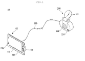
- FIG. 1 illustrates a navigation system according to an embodiment of the present invention.
- the navigation system 10 may include a vehicle navigation system 100 and a vehicle black box 200.
- the navigation system 10 may be a system that informs a driver or a passenger of a vehicle of information about driving and maintenance of the vehicle.
- the navigation system 10 may be the vehicle navigation system 100 in a narrow sense and may be a system including various electronic devices connected with the vehicle navigation system 100 by wire or wirelessly in a broad sense. That is, electronic devices capable of complementing and augmenting the function of the vehicle navigation system 100 can be connected with the vehicle navigation system 100 to implement the integrated navigation system 10.
- the electronic devices capable of implementing the navigation system 10 by being connected with the vehicle navigation system 100 may include a mobile terminal that can be linked to a mobile communication network, a remote controller, etc.
- the electronic devices may include the vehicle black box 200.
- the vehicle black box 200 may be integrated with or separated from the vehicle navigation system 100. While FIG. 1 shows that the vehicle black box 200 is provided separately from the vehicle navigation system 100 and connected with the vehicle navigation system 100 through a communication cable 300, the vehicle black box 200 can be integrated with the vehicle navigation system 100.
- the vehicle navigation system 100 may include a display 145 attached to the front of a navigation housing 191, a navigation operation key 193, and a navigation microphone 195.
- the navigation housing 191 forms the external appearance of the vehicle navigation system 100.
- the vehicle navigation system 100 may be exposed to various external environments such as high or low temperature for seasonal reason, direct/indirect external shocks, etc.
- the navigation housing 191 may protect internal electronic components of the vehicle navigation system 100 from external environment variations and make the external appearance of the vehicle navigation system 100 beautiful.
- the navigation housing 191 may be formed by injection molding using a material such as ABS, PC or reinforced engineering plastics.
- the display 145 visually displays various types of information.
- Information displayed on the display 145 may include map data combined with route information, images of broadcast programs including DMB broadcast programs, and images stored in a memory.
- the display 145 may be divided into several regions physically or logically. Physically divided displays mean two or more displays connected to each other. Logically divided displays mean a display of a plurality of independent screens on one display 145. For example, route information is displayed on part of the display 145 while a received DMB broadcast program is displayed on the display 145, or a map and the DMB broadcast program are respectively displayed on different regions of the display 145. With the tendency of convergence of various functions into the vehicle navigation system 100, the display 145 is increasingly logically divided to display various types of information. Furthermore, to display a large amount of information, the screen of the display 145 becomes larger.
- All or some of the surface of the display 145 may be a touchscreen capable of receiving a touch input from a user.
- the touchscreen function can be activated by touching a function selection button displayed on the display 145. That is, the display 145 can function as both an output unit 140 shown in FIG. 3 and an input unit 120 shown in FIG. 3 .
- the navigation operation key 193 may be provided to execute various functions of the vehicle navigation system 100 or to allow a user to directly input necessary data. Frequently used specific functions may be mapped to the navigation operation key 193 to improve user convenience.
- the navigation microphone 195 may be provided to receive sounds including voices. For example, a specific function of the navigation device 100 can be executed on the basis of a voice signal received through the navigation microphone 195. Furthermore, it is possible to detect a current state of the vehicle, such as an accident, on the basis of a sound signal received through the navigation microphone 195.
- the vehicle block box 200 may store information necessary for a procedure of dealing with an accident by exchanging signals with the vehicle navigation system 100. For example, When an accident occurs while the vehicle runs, it is possible to analyze an image acquired by the vehicle black box 200 and use the image to determine the details of the accident and a degree of the accident. Furthermore, the vehicle black box 200 connected to the vehicle navigation system 100 can use information stored in the vehicle navigation system 100. For example, it is possible to map images obtained from the vehicle black box 200 with map data stored in the vehicle navigation system 100 to improve the utility of the vehicle black box 200.
- the vehicle black box 200 can obtain information on the vehicle when the vehicle runs or stops. That is, the vehicle black box 200 can capture an image not only when the vehicle runs but also when the vehicle stops.
- the quality of an image obtained through the vehicle black box 200 may be fixed or variable. For example, the picture quality can be increased in the event of an accident and decreased in a normal case so as to store a salient image while minimizing a necessary storage space.
- the vehicle black box 200 may include a black box camera 222, a black box microphone 224, and an attachment part 281.
- the black box camera 222 can take pictures of the inside and outside of the vehicle.
- the vehicle black box 200 may include one or more black box cameras 222.
- the black box cameras 222 may be integrated with the vehicle black box 200 and others may be attached to portions of the vehicle to capture images and transmit the captured images to the vehicle black box 200.
- the black box camera 222 may be installed such that it can photograph a forward view of the vehicle. Images captured by the black box camera 222 may be stored in the vehicle black box 200 or the vehicle navigation system 100.
- the black box microphone 224 may acquire a sound generated from the inside or outside of the vehicle.
- the black box microphone 224 may execute functions similar to those of the above-mentioned navigation microphone 195.
- the attachment part 281 may fix the vehicle black box 200 to the vehicle.
- the attachment part 281 may be a suction plate capable of attaching the vehicle black box 200 to the windshield of the vehicle or a fixing device capable of combining the vehicle black box 200 with the room mirror of the vehicle.
- FIG. 2 illustrates a navigation system according to another embodiment of the present invention. Only parts different from the above-described embodiment will now be described.
- the navigation system 10 may be wirelessly connected to the vehicle navigation system 100 and the vehicle block box 200. That is, the vehicle navigation system 100 and the vehicle black box 200 may be separate devices having no physical connecting device therebetween.
- the vehicle navigation system 100 and the vehicle black box 200 may communicate with each other through Bluetooth, RFID (Radio Frequency Identification), IrDA (Infrared Data Association), UWB (Ultra WideBand), ZigBee, etc.
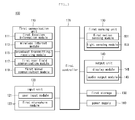
- FIG 3 is a block diagram of the vehicle navigation system 100 shown in FIG. 1 .
- the vehicle navigation system 100 may include a first communication unit 110, an input unit 120, a first sensing unit 130, an output unit 140, a first storage 150, a power supply 160, and a first controller 170.
- the first communication unit 100 is provided for the vehicle navigation system 100 to communicate with other devices.
- the first communication unit 100 may include a first location information module 111, a wireless Internet module 113, a broadcast transmitting/receiving module 115, a first near field communication module 117, and a first wired communication module 119.
- the first location information module 111 acquires location information through a GNSS (Global Navigation Satellite System).
- the GNSS is a navigation system that calculates the location of a receiver terminal using a radio signal received from an artificial satellite (20 shown in FIG. 5 ).
- Examples of the GNSS may include GPS (Global Positioning System), Galileo, GLONASS (Global Orbiting Navigational Satellite System), COMPASS, IRNSS (Indian Regional Navigational Satellite System), QZSS (Quasi-Zenith Satellite System), etc.
- the first location information module of the vehicle navigation system 100 may obtain location information by receiving a GNSS signal provided in an area where the vehicle navigation system 100 is used.
- the wireless Internet module 113 acquires information or transmits information by accessing wireless Internet.
- the wireless Internet accessible by the wireless Internet module 113 may include WLAN (Wireless LAN), WiBro (Wireless Broadband), Wimax (World interoperability for microwave access), HSDPA (High speed Downlink Packet Access), etc.
- the broadcast transmitting/receiving module 115 transmits/receives broadcast signals through broadcasting systems.
- the broadcasting systems may include DMBT (Digital Multimedia Broadcasting Terrestrial), DMSS (Digital Multimedia Broadcasting Satellite), MediaFLO (Media Forward Link Only), DVBH (Digital Video Broadcast Handheld), ISDBT (Integrated Services Digital Broadcast Terrestrial), etc.
- Broadcast signals transmitted/received through the broadcast transmitting/receiving module 115 may include traffic information, living information, images captured by the vehicle black box (200 shown in FIG. 1 ), etc.
- the first near field communication module 117 is a device for near field communication.
- the first near field communication module 117 can perform communication through Bluetooth, RFID, IrDA, UWB, ZigBee, etc.
- the first wired communication module 119 is an interface capable of connecting the vehicle navigation system 100 to other devices by wire.
- the first wired communication module 119 may be a USB module capable of performing communication through a USB port.
- the vehicle navigation system 100 according to embodiments of the present invention can communicate with other devices through the first near field communication module 117 or the first wired communication module 119. Furthermore, when the vehicle navigation system 100 communicates with a plurality of devices, the vehicle navigation system 100 may communicate with one of the devices through the first near field communication module 117 and communicate with the other through the first wired communication module 119.
- the input unit 120 converts an external physical input applied to the vehicle navigation system 100 into an electric signal.
- the input unit 120 may include a user input module 121 and a first microphone module 123.
- the user input module 121 is a key input unit through which a user can apply an input through a push operation.
- the user input module 121 may be implemented as the navigation operation key (193 shown in FIG. 1 ) provided to the exterior of the housing (191 shown in FIG. 1 ) of the vehicle navigation system 100.
- the first microphone module 123 receives a user voice and a sound generated from the inside or outside of the vehicle.
- the first microphone module 123 may be implemented as the navigation microphone (195 shown in FIG. 1 ) provided to the exterior of the housing (191 shown in FIG. 1 ) of the vehicle navigation system 100.
- the first sensing unit 130 senses a current state of the vehicle navigation system 100.
- the first sensing unit 130 may include a first motion sensing module 131 and a light sensing module 133.
- the first motion sensing module 131 may sense a three-dimensional motion of the vehicle navigation system 100.
- the first motion sensing module 131 may include a 3-axis geomagnetic sensor and a 3-axis acceleration sensor. It is possible to calculate a more accurate trace of the vehicle equipped with the vehicle navigation system 100 by combining motion information acquired through the first motion sensing module 131 with location information obtained through the location information module 111.
- the light sensing module 133 measures surrounding illuminance of the vehicle navigation system 100. It is possible to control the brightness of the display 145 to be varied with the surrounding illuminance using illuminance information acquired through the light sensing module 133.
- the output unit 140 outputs information on the vehicle navigation system 100.
- the output unit 140 may include a display module 141 and an audio output module 143.
- the display module 141 outputs visually recognizable information about the vehicle navigation system 100.
- the display module 141 may be implemented as the display (145 shown in FIG. 1 ) provided to the front of the housing (191 shown in FIG. 1 ) of the vehicle navigation system 100. If the display module 141 is a touchscreen, the display module 141 can function as both the output unit 140 and the input unit 120, as described above.
- the audio output module 143 outputs auditorily recognizable information about the vehicle navigation system 100.
- the audio output module 143 may be implemented as a speaker outputting information that needs to be signaled to users including a driver as sound.
- the first storage 150 stores information necessary for operation of the vehicle navigation system 100 and information generated according to the operation.
- the first storage 150 may be a memory built in the vehicle navigation system 100 or a detachable memory.
- the information necessary for the operation of the vehicle navigation system 100 may include an OS, route search application, map, etc.
- the information generated according to the operation of the vehicle navigation system 100 may include information about a searched route, a received image, etc.
- the power supply 160 supplies power necessary for the operation of the vehicle navigation system 100 or operations of other devices connected to the vehicle navigation system 100.
- the power supply 160 may be a device provided with power from a battery set in the vehicle navigation system 100 or an external power supply.
- the power supply 160 may be implemented as the first wired communication module 119 or a device wirelessly provided with power, according to power supply form.
- the first controller 170 outputs control signals for controlling operations of the vehicle navigation system 100. Furthermore, the first controller 170 may output control signals for controlling other devices connected to the vehicle navigation system 100.
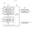
- FIG. 4 is a block diagram of the vehicle black box 200 shown in FIG. 1 .
- the vehicle black box 200 may include a second communication unit 210, an AV input unit 220, a user input unit 230, a second sensing unit 240, and a second storage 250.
- the second communication unit 210 may communicate with the first communication unit 110 of the vehicle navigation system (100 shown in FIG. 3 ) or other devices.
- the second communication unit 210 may include a second location information module 211, a second near field communication module 213, and a second wired communication module 215.
- the second location information module 211 performs an operation similar to that of the first location information module (111 shown in FIG. 3 ).
- the second near field communication module 213 can communicate with the first near field communication module (117 shown in FIG. 3 ) and the second wired communication module 215 can communicate with the first wired communication module (119 shown in FIG. 3 ).
- the AV input unit 220 may acquire sounds and images.
- the AV input unit 220 may include a camera module 221 and a second microphone module 223.
- the camera module 221 may capture images of the inside and outside of the vehicle equipped with the vehicle black box 200.
- the camera module 221 may be implemented as the black box camera (222 shown in FIG. 1 ), as described above.
- the second microphone module 223 may obtain sounds generated from the inside and outside of the vehicle.
- the sounds obtained through the second microphone module 223 may be used to control operation of the vehicle black box 200.
- the camera module 221 can be controlled to capture an image with higher resolution.
- the second microphone module 223 may be implemented as the black box microphone 224.
- the user input unit 230 is a device through which a user directly operates the vehicle black box 200.
- the user input unit 230 may be implemented as a push button (not shown) provided to the exterior of the vehicle black box 200. If the vehicle black box 200 is controlled by a control signal of the first controller (170 shown in FIG. 3 ) of the vehicle navigation system (100 shown in FIG. 3 ), the user input unit 230 may be excluded from the vehicle black box 200.
- the second sensing unit 240 may sense a current state of the vehicle black box 200.
- the second sensing unit 240 may include a second motion sensing module 241 and performs an operation similar to that of the first motion sensing module (131 shown in FIG. 3 ). If the second sensing unit 240 is included in the vehicle black box 200, the second sensing unit 240 may not receive information about a three-dimensional motion from the vehicle navigation device 100.
- the second storage 250 stores information necessary for operations of the vehicle black box 200 and information generated according to the operations of the vehicle black box 200.
- the information stored in the second storage 250 may be images captured by the camera module 221.
- the second storage 250 may be included in the vehicle black box 200 or may be a memory detachably set in the vehicle black box 200.
- the second controller 270 outputs control signals for controlling operations of the vehicle black box 200.
- the second controller 270 may be affected by control signals of the first controller (170 shown in FIG. 3 ) of the vehicle navigation system (100 shown in FIG. 3 ). That is, the second controller 270 may be dependent on the first controller (170 shown in FIG. 3 ).
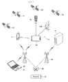
- FIG. 5 illustrates a configuration of a communication network including the navigation system 10 shown in FIG. 1 .
- the navigation system 10 may be linked with various communication networks and other electronic devices 61 to 64.
- the navigation system 10 may calculate a current location thereof using radio signals received from artificial satellites 20.
- the artificial satellites 20 may transmit L-band frequency signals having different frequency bands.
- the navigation system 10 can calculate the current location thereof on the basis of a time required for the L-band frequency transmitted from each artificial satellite 20 to arrive at the navigation system 10.
- the navigation system 10 may wirelessly access a network 30 through a control station (ACR) 40 and a base station (RAS) 50 via the first communication unit (110 shown in FIG. 3 ).
- ACR control station
- RAS base station
- the navigation system 10 can exchange information with the electronic devices 61 and 62 linked to the network 30 by being indirectly with the electronic devices 61 and 62.
- the navigation system 10 may indirectly access the network 30 through another device 63 having a communication function. For example, if the navigation system 10 does not include a device through which the navigation system 10 access the network 30, the navigation system 10 can communicate with the other device 63 having the communication function through the first near field communication module (117 shown in FOG. 3) or the like.
- mapping image data with location data An operation of mapping image data with location data according to an embodiment of the present invention will now be described with reference to FIGS. 6 to 9 .
- FIGS. 6 to 9 are flowcharts illustrating the operation of mapping image data with location data according to an embodiment of the present invention.
- the vehicle navigation system (100 shown in FIG. 3 ) maps image data received from the vehicle black box (200 shown in FIG. 4 ) with location data, place data, etc. and stores the mapped data in the first storage (150 shown in FIG. 3 ).
- the place data is obtained from map data which is stored in the first storage (150 shown in FIG. 3 ) using location data acquired through the first location information module (111 shown in FIG. 3 ) of the vehicle navigation system (100 shown in FIG. 3 ) or the second location information module (211 shown in FIG. 4 ) of the vehicle black box (200 shown in FIG. 4 ) and includes address information, road information, POI (Point of Interest) information, etc.
- the location data includes longitude information, latitude information, etc.
- the map data stores not only map information but also place information and position information corresponding thereto. Accordingly, it is possible to obtain place data using location data corresponding thereto.
- the address information is an identifier for identifying a place, which is given by a national institution, a public institution or the like.
- the address information may be a full address such as "31, Taepyung-no 1-ga, Jung-gu, Seoul” or part of a full address, such as "Taepyung-no 1-ga, Jung-gu, Seoul” or "Yeoksam-dong".
- the road information is an identifier for identifying a road, which is given by a national institution, a public institution, or the like.
- the road information may be "Seoul outer ring road", "Route 4", etc.
- the POI information may correspond to a widely known place such as "Gwanghwamun square” or “City hall square", a subway station name such as “Gangnam station” or “Sadang station”, a place name such as “Seorae village”, a company name such as "Lotteria” or “Starbucks”, a national institution or a public institution such as “Seoul City hall” or “Jongno-gu office”, or the like. It is possible to designate a specific place such as “Home", “Office” or the like as POI by a user.
- the image data may be obtained through the vehicle black box (200 shown in FIG. 4 ) for a predetermined time.
- the image data can be data having a predetermined play time such as one minute, five minutes, etc.
- the image data may be data having a predetermined size.
- the image data may have a predetermined size of 1MB, 5MB or the like.
- the vehicle black box (200 shown in FIG. 4 ) may transmit image data obtained by capturing the inside of outside of the vehicle to the vehicle navigation system (100 shown in FIG. 3 ) periodically or at the request of the vehicle navigation system (100 shown in FIG. 3 ).
- the second communication unit (210 of FIG. 4 ) of the vehicle black box (200 of FIG. 4 ) transmits image data obtained by photographing the inside and outside of the vehicle to the vehicle navigation device (100 of FIG. 3 ) in real time (S411).
- the first communication unit (110 of FIG. 3 ) of the vehicle navigation system (100 of FIG. 3 ) acquires current location data about the vehicle (S413) and the first controller (170 of FIG. 3 ) obtains location data from the map data stored in the first storage (150 of FIG. 3 ) using the current location data (S415).
- the first controller (170 of FIG. 3 ) of the vehicle navigation system (100 of FIG. 3 ) maps the image data received from the vehicle black box (200 of FIG. 4 ) with the location data and stores the mapped data in the first storage (150 of FIG. 3 ) (S417).
- steps S413 and S415 are performed after step S411 in the present embodiment, steps S413 and S415 may be performed prior to step S411 or carried out simultaneously with step S411.
- the second communication unit (210 of FIG. 4 ) of the vehicle black box (200 of FIG. 4 ) obtains location data about the vehicle (S421) and transmits image data mapped with the location data to the vehicle navigation system (100 of FIG. 3 ) (S423).
- the first communication unit (110 of FIG. 3 ) of the vehicle navigation system (100 of FIG. 3 ) receives the image data from the vehicle black box (200 of FIG. 4 ) and the first controller (170 of FIG. 3 ) acquires location data from the map data stored in the first storage (150 of FIG. 3 ) using the location data mapped with the received image data (S425).
- the first controller (170 of FIG. 3 ) of the vehicle navigation system (100 of FIG. 3 ) maps the received image data with the location data and stores the mapped data in the first storage (150 of FIG. 3 ) (S427).
- the first communication unit (110 of FIG. 3 ) of the vehicle navigation system (100 of FIG. 3 ) obtains location data regarding the vehicle (S431) and transmits the obtained location data to the vehicle black box (200 of FIG. 4 ) (S433). Then, the second communication unit (210 of FIG. 4 ) of the vehicle black box (200 of FIG. 4 ) receives the location data from the vehicle navigation system (100 of FIG. 3 ) and transmits image data mapped with the location data to the vehicle navigation system (100 of FIG. 3 ) (S435). Subsequently, the first communication unit (110 of FIG. 3 ) of the vehicle navigation system (100 of FIG. 3 ) receives the image data from the vehicle black block (200 of FIG.
- the first controller (170 of FIG. 3 ) and the first controller (170 of FIG. 3 ) acquires location data from the map data stored in the first storage (150 of FIG. 3 ) using the location data mapped with the received image data (S437).
- the first controller (150 of FIG. 3 ) of the vehicle navigation system (100 of FIG. 3 ) maps the received image data with the location data and stores the mapped data in the first storage (150 of FIG. 3 ).
- the first communication unit (110 of FIG. 3 ) of the vehicle navigation system (100 of FIG. 3 ) obtains location data regarding the vehicle (S441) and acquires location data from the map data stored in the first storage (150 of FIG. 3 ) using the obtained location data (S443). Then, the first communication unit (110 of FIG. 3 ) of the vehicle navigation system (100 of FIG. 3 ) transmits the location data acquired from the map data to the vehicle black box (200 of FIG. 4 ) through the first communication unit (100 of FIG. 3 ) (S445).
- the second communication unit (210 of FIG. 4 ) of the vehicle black box (200 of FIG. 4 ) receives the location data from the vehicle navigation system (100 of FIG.
- the first communication unit (110 of FIG. 3 ) of the vehicle navigation system (100 of FIG. 3 ) receives the image data from the vehicle black block (200 of FIG. 4 ) and the first controller (170 of FIG. 3 ) stores the image data in the first storage (150 of FIG. 3 ) (S449).
- mapping image data with location data The operation of mapping image data with location data according to the present invention will now be described in more detail.
- the first controller (170 of FIG. 3 ) of the vehicle navigation system (100 of FIG. 3 ) may store location data mapped with image data in the form of a separate file in the first storage 150. That is, the first controller (170 of FIG. 3 ) can store the location data in a folder in which the image data is stored with a file name of the location data, which equals to the file name of the image data.
- the location data may include time information and may be synchronized with the image data using the time information.
- the location data includes information about "place A” and information about "place B”, which respectively correspond to time information of "0 to 5 minutes” and "5 to 10 minutes”.
- the first controller (170 of FIG. 3 ) of the vehicle navigation system (100 of FIG. 3 ) can map location data to video frames of a predetermined video frame type from among video frames corresponding to the image data.
- Video frame types include I (Intra) frame, P (Predicted) frame and B (Bidirectional) frame.
- I Intra
- P Predicted
- B Bidirectional
- the location data is mapped to I frame from among the video frames of the image data.
- the first controller (170 of FIG. 3 ) of the vehicle navigation system (100 of FIG. 3 ) may map the location data with the image data at predetermined intervals.
- the first controller (170 of FIG. 3 ) of the vehicle navigation system (100 of FIG. 3 ) can map the location data with the image data at a predetermined interval of one minute or 5 minutes.
- the first controller (170 of FIG. 3 ) of the vehicle navigation system (100 of FIG. 3 ) may map current location data obtained using current location data regarding a vehicle with the image data when the current location data is different from previous location data obtained using previous location data of the vehicle. For example, if location data obtained according to location data of the vehicle corresponds to a first place (Gangnam station), a second place (Gangnam station) and a third place (Yeoksam station), the second place (Gangnam station) is not mapped with the image data because the second place is equal to a previous place corresponding to the first place (Gangnam station) whereas the third place (Yeoksam station) is mapped with the image data because the third place is different from the previous place, that is, the second plate (Gangnam station).
- the vehicle navigation system (100 of FIG. 3 ) maps location data with image data in the above description
- the vehicle black box (200 of FIG. 4 ) can map location data and place data with image data in the same manner.
- the first controller (170 of FIG. 3 ) of the vehicle navigation system (100 of FIG. 3 ) can classify image data according to image data type and store classified the image data. That is, the first controller (170 of FIG. 3 ) of the vehicle navigation system (100 of FIG. 3 ) can classify folders according to image data type and store image data in a corresponding folder, or store image data with a file name including the image data type corresponding to the image data.
- Image data types include image data (referred to as “first image data type” hereinafter) obtained from a signal of a sensor set in the vehicle, image data (referred to as “second image data type” hereinafter) obtained according to operation of a user, and image data (referred to as “third image data type” hereinafter) obtained according to operation of the vehicle black box (200 of FIG. 4 ). That is, the first image data type (“event shown in FIG. 10 and “E” shown in FIG. 13 ) corresponds to image data obtained by photographing the inside or outside of the vehicle according to a signal of a sensor which senses external impact applied to the vehicle, speeding, rapid acceleration, rapid reduction, etc. of the vehicle, or external noise.
- the second image data type (“manual” shown in FIG.
- the third image data type (“anytime” shown in FIG. 10 and "A” shown in FIG. 13 ) corresponds to image data obtained by photographing the inside and/or outside of the vehicle while the vehicle black box (200 of FIG. 4 ) normally operates.
- the first controller (170 of FIG. 3 ) of the vehicle navigation system (100 of FIG. 3 ) can classify image data according to location data and store the classified image data. That is, the first controller (170 of FIG. 3 ) of the vehicle navigation system (100 of FIG. 3 ) can classify folders according to location data and store image data in a corresponding folder, or store image data with a file name including the location data. When a plurality of location data are mapped with one image data, the image data can be divided into a plurality of image data pieces and stored.
- the vehicle navigation system (100 of FIG. 3 ) stores image data in the above description
- the vehicle black box (200 of FIG. 4 ) can store image data in the same manner.
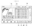
- FIG. 10 illustrates an exemplary image data list screen according to an embodiment of the present invention.
- the vehicle navigation system (100 of FIG. 3 ) displays the image data list screen as shown in FIG. 10 on the display (145 of FIG. 1 ).
- the image data list screen includes an image display screen VS for displaying image data, an image list screen LS, a delete button DB, a backup button BB, a map button MB, a search button SB, etc.
- the image list screen SL displays a list of image data stored in the first storage (150 of FIG. 3 ) of the vehicle navigation system (100 of FIG. 3 ).
- the first controller (170 of FIG. 3 ) of the vehicle navigation system (100 of FIG. 3 ) may display a list of image data stored in the second storage (250 of FIG. 4 ) of the vehicle black box (200 of FIG. 4 ) on the image list screen LS. That is, upon selection of the image display menu by the user, the first controller (170 of FIG. 3 ) of the vehicle navigation system (100 of FIG. 3 ) can receive the image data list from the vehicle black box (200 of FIG. 4 ) and display the received image data list on the image list screen LS.
- the vehicle navigation system (10 of FIG. 3 ) of the vehicle navigation system (100 of FIG. 3 ) may display statuses, such as 'connected', 'connection complete', 'connection fail', etc. on the display (145 of FIG. 1 ). Accordingly, the user can check whether the vehicle navigation system (10 of FIG. 3 ) is connected with the vehicle black box (200 of FIG. 4 ), whether connection of the vehicle navigation system (10 of FIG. 3 ) with the vehicle black box (200 of FIG. 4 ) fails, or whether the vehicle navigation system (10 of FIG. 3 ) and the vehicle black box (200 of FIG. 4 ) are being connected to each other.
- An image selected by the user from the image data list displayed on the image list screen LS may be displayed in a different color or may be shaded, for example, such that the user can recognize the currently selected image.
- the image data list may be displayed differently according to image data type using a tab. Furthermore, a corresponding image data type can be indicated for each item displayed on the image list screen LS.
- An image selected by the user from the image data list displayed on the image list screen LS is displayed on the image display screen VS.
- the image display screen VS is changed to a full screen.
- the full screen can be returned to the image display screen VS in the original size.
- location data and place data mapped to image data can be displayed along with the image on the image play screen VS.
- the image data includes speed information
- the speed information can also be displayed on the image display screen VS.
- the delete button DB is used to delete currently selected image data.
- the first controller (170 of FIG. 3 ) of the vehicle navigation system (100 of FIG. 3 ) deletes the currently selected image data.
- the image data list displayed on the image list screen LS is received from the vehicle black box (200 of FIG. 4 )
- the first controller (170 of FIG. 3 ) of the vehicle navigation system (100 of FIG. 3 ) requests the vehicle black box (200 of FIG. 4 ) to delete the currently selected image data.
- the second controller (270 of FIG. 4 ) of the vehicle black box (200 of FIG. 4 ) deletes the corresponding image data.
- the backup button BB is used to store the currently selected image data as a backup.
- the first controller (170 of FIG. 3 ) of the vehicle navigation system (100 of FIG. 3 ) stores the currently selected image data as a backup.
- the image data list displayed on the image list screen LS is received from the vehicle black box (200 of FIG. 4 )
- the first controller (170 of FIG. 3 ) of the vehicle navigation system (100 of FIG. 3 ) requests the vehicle black box (200 of FIG. 4 ) to store the currently selected image data as a backup.
- the second controller (270 of FIG. 4 ) of the vehicle black box (200 of FIG. 4 ) stores the corresponding image data as a backup.
- the map button MB is used to provide a simulation driving function or a location view function.
- a simulation driving menu and a location view menu are displayed on the display (145 of FIG. 1 ) in the form of a pop-up window, for example.
- the corresponding function is executed. If location data and place data are not mapped with the currently selected image data, the map button MB may be disabled.
- the search button SB is used to search an image.
- FIGS. 11 , 12 and 13 A search function according to an embodiment of the present invention will now be described with reference to FIGS. 11 , 12 and 13 .
- FIG. 11 is a flowchart illustrating the search function according to an embodiment of the present invention
- FIG. 12 shows an example of a search word input screen according to an embodiment of the present invention
- FIG. 13 shows an example of a search result screen according to an embodiment of the present invention.
- the search word input screen includes a search word input part SW and a keyboard part KI.
- the user can input a desired search word (place data) into the search word input part SW through the keyboard part KI.
- the first controller (170 of FIG. 3 ) of the vehicle navigation system (100 of FIG. 3 ) searches video frames of the reproduced image data for a video frame mapped to the place data input by the user (S515).
- the first controller (170 of FIG. 3 ) of the vehicle navigation system (100 of FIG. 3 ) searches the first storage (150 of FIG. 3 ) for image data mapped to the place data input by the user (S519).
- the first controller (170 of FIG. 3 ) of the vehicle navigation system (100 of FIG. 3 ) may request the vehicle black box (200 of FIG. 4 ) to search the corresponding image data and receive a search result from the vehicle black box (200 of FIG. 4 ).
- the first controller (170 of FIG. 3 ) of the vehicle navigation system (100 of FIG. 3 ) displays the search result on the display (145 of FIG. 1 ).
- the search result screen displays a list of image data mapped with the place data input by the user.
- Each item is composed of an image data file name part FN, an additional information part AI, and an image data type part VT.
- Address information ((a) of FIG. 13 ) or POI information ((b) of FIG. 13 ) may be displayed in the additional information part AI.
- An image data type may be displayed in the image data type part VT. Accordingly, the user can recognize whether image data has been obtained according to a signal of a sensor attached to the vehicle, obtained at the request of the user, or obtained when the vehicle black box (200 of FIG. 4 ) is operated.
- the first controller (170 of FIG. 3 ) of the vehicle navigation system (100 of FIG. 3 ) may display a video frame (thumbnail image) list instead of the image data list on the search result screen 145.
- time information of the video frame may be displayed in the image data file name part FN.
- time information such as "1:10 ⁇ 3:20" can be displayed in the image data file name part FN.
- place data is mapped with image data, as described above, the user can easily search the corresponding image data or video frame using the place data.
- FIG. 14 is a flowchart illustrating the simulation driving function according to an embodiment of the present invention and FIG. 15 shows an example of a simulation driving screen according to an embodiment of the present invention.
- the first controller (170 of FIG. 3 ) of the vehicle navigation system (100 of FIG. 3 ) obtains vehicle moving route information using location data mapped with currently selected image data (S613).
- the vehicle moving route information includes a plurality of location data which are arranged with the lapse of time.
- the first controller (170 of FIG. 3 ) of the vehicle navigation system (100 of FIG. 3 ) displays the image data and the vehicle moving route information on the display (145 of FIG. 1 ).
- a vehicle moving route ML is displayed on a map.
- the video display screen VS displays the currently selected image data.
- a vehicle position VP is updated when image data is reproduced.
- the video play screen VS may be displayed in the form of PIP (Picture In Picture), NIP (Navigation In Picture) or the like.
- moving route information of an accident vehicle can be confirmed in the event of a car accident by displaying moving route information obtained using location data mapped with image data, and thus the moving route information can be used as reference data to determine the cause of the accident.
- FIG. 16 is a flowchart illustrating the location view function according to an embodiment of the present invention and FIG. 17 shows an example of a location view screen according to an embodiment of the present invention.
- the first controller (170 of FIG. 3 ) of the vehicle navigation system (100 of FIG. 3 ) displays currently selected image data on the display (145 of FIG. 1 ).
- the first controller (170 of FIG. 3 ) of the vehicle navigation system (100 of FIG. 3 ) obtains, from all images corresponding to the image data, some images corresponding to a predetermined time on the basis of the specific location (S713).
- the first controller (170 of FIG. 3 ) of the vehicle navigation system (100 of FIG. 3 ) displays the obtained images on the display (145 of FIG. 1 ).
- the specific location IP input by the user is displayed on the map.
- the images corresponding to the predetermined time on the basis of the specific location IP are iteratively played on the video play screen VS. For example, when the user inputs a specific location while the image data is reproduced, images corresponding to one minute or 5 minutes based on the specific location are iteratively played.
- the image data list screen shown in FIG. 10 , the search word input screen shown in FIG. 12 , the search result screen shown in FIG. 3 , the simulation driving screen shown in FIG. 15 and the location view screen shown in FIG. 17 are exemplary and they may be configured in other forms.
- the vehicle navigation system (100 of FIG. 3 ) or the vehicle black box (200 of FIG. 4 ) can transmit the image data mapped with location data and place data to the electronic devices (61 and 62 of FIG. 5 ) through the network (30 of FIG. 5 ). Then, the electronic devices (61 and 62 of FIG. 5 ) store the image data received from the vehicle navigation system (100 of FIG. 3 ) or the vehicle black box (200 of FIG. 4 ). In addition, the electronic devices (61 and 62 of FIG. 5 ) can transmit the image data to the vehicle navigation system (100 of FIG. 3 ) or the vehicle black box (200 of FIG. 4 ) at the request of the vehicle navigation system (100 of FIG. 3 ) or the vehicle black box (200 of FIG. 4 ).
- the method for controlling the vehicle navigation system may be implemented as code that can be written to a computer-readable recording medium and can thus be read by a processor.
- the computer-readable recording medium may be any type of recording device in which data can be stored in a computer-readable manner. Examples of the computer-readable recording medium include a ROM, a RAM, a CD-ROM, a magnetic tape, a floppy disc, an optical data storage, and a carrier wave (e.g., data transmission through the Internet).
- the computer-readable recording medium can be distributed over a plurality of computer systems connected to a network so that computer-readable code is written thereto and executed therefrom in a decentralized manner. Functional programs, code, and code segments needed for realizing the embodiments herein can be construed by one of ordinary skill in the art.
Applications Claiming Priority (2)
| Application Number | Priority Date | Filing Date | Title |
|---|---|---|---|
| KR1020100006153A KR101019914B1 (ko) | 2010-01-22 | 2010-01-22 | 내비게이션 시스템 및 차량용 내비게이션의 제어방법 |
| PCT/KR2011/000160 WO2011090286A2 (fr) | 2010-01-22 | 2011-01-11 | Système de navigation et procédé de commande de navigation d'un véhicule |
Publications (3)
| Publication Number | Publication Date |
|---|---|
| EP2515079A2 true EP2515079A2 (fr) | 2012-10-24 |
| EP2515079A4 EP2515079A4 (fr) | 2013-09-25 |
| EP2515079B1 EP2515079B1 (fr) | 2017-03-08 |
Family
ID=43938495
Family Applications (1)
| Application Number | Title | Priority Date | Filing Date |
|---|---|---|---|
| EP11734835.9A Active EP2515079B1 (fr) | 2010-01-22 | 2011-01-11 | Système de navigation et procédé de commande de navigation d'un véhicule |
Country Status (5)
| Country | Link |
|---|---|
| US (1) | US9163947B2 (fr) |
| EP (1) | EP2515079B1 (fr) |
| KR (1) | KR101019914B1 (fr) |
| CN (1) | CN102741657B (fr) |
| WO (1) | WO2011090286A2 (fr) |
Cited By (1)
| Publication number | Priority date | Publication date | Assignee | Title |
|---|---|---|---|---|
| EP3605474A4 (fr) * | 2017-11-15 | 2020-06-03 | JVC Kenwood Corporation | Dispositif de détection d'anomalie, procédé de détection d'anomalie, programme d'ordinateur de détection d'anomalie et dispositif d'enregistrement de véhicule |
Families Citing this family (15)
| Publication number | Priority date | Publication date | Assignee | Title |
|---|---|---|---|---|
| TW200948065A (en) * | 2008-05-06 | 2009-11-16 | Flexmedia Electronics Corp | Method and apparatus for simultaneously playing video frame and trip information and controller thereof |
| KR101474937B1 (ko) | 2012-01-27 | 2014-12-19 | 주식회사 케이티 | 블랙박스 기능과 내비게이션 기능을 구비한 통신 단말 및 영상 데이터 저장 방법 |
| CN103033836B (zh) * | 2012-12-19 | 2014-07-02 | 江苏科技大学 | 一种车载导航指向装置的导航指向方法 |
| KR20150002015A (ko) * | 2013-06-28 | 2015-01-07 | 주식회사 코아로직 | 블랙박스 영상 표시 방법 및 장치 |
| JP6390323B2 (ja) * | 2014-02-24 | 2018-09-19 | 日本精機株式会社 | 車両用情報提供装置 |
| JP6435658B2 (ja) * | 2014-06-20 | 2018-12-12 | 株式会社デンソー | ドライブレコーダーおよびドライブレコーダー用のプログラム |
| KR102276082B1 (ko) * | 2014-10-24 | 2021-07-12 | 팅크웨어(주) | 내비게이션 장치, 블랙 박스 및 그들의 제어 방법 |
| CN104598427A (zh) * | 2014-12-29 | 2015-05-06 | 江苏科技大学 | 基于嵌入式gpu系统的并行化复合导航指向系统及方法 |
| CN105205880B (zh) * | 2015-07-17 | 2018-03-16 | 广东好帮手电子科技股份有限公司 | 一种基于地理位置检索数据的方法及其系统 |
| US10459616B2 (en) * | 2016-04-15 | 2019-10-29 | Toyota Motor Engineering & Manufacturing North America, Inc. | Automatic full screen display |
| JP6569698B2 (ja) * | 2017-04-17 | 2019-09-04 | 株式会社Jvcケンウッド | 記録制御装置、記録装置、ナビゲーション装置、記録方法、及びプログラム |
| JP6825500B2 (ja) * | 2017-06-30 | 2021-02-03 | 株式会社Jvcケンウッド | ドライブレコーダ運用システム、ドライブレコーダ、運用方法および運用プログラム |
| JP6593431B2 (ja) * | 2017-12-27 | 2019-10-23 | 株式会社Jvcケンウッド | 記録制御装置、記録装置、記録制御方法及び記録制御プログラム |
| KR102164753B1 (ko) * | 2018-01-04 | 2020-10-13 | (주)카네비컴 | 라이다 블랙박스 및 이에 있어서 사물 탐지 방법 |
| US10976733B2 (en) * | 2018-09-26 | 2021-04-13 | Ford Global Technologies, Llc | Interfaces for remote trailer maneuver assist |
Citations (6)
| Publication number | Priority date | Publication date | Assignee | Title |
|---|---|---|---|---|
| JP2003112671A (ja) * | 2001-10-04 | 2003-04-15 | Riki Mano | 走行体の運転状況記録装置 |
| US6570609B1 (en) * | 1999-04-22 | 2003-05-27 | Troy A. Heien | Method and apparatus for monitoring operation of a motor vehicle |
| WO2007063849A1 (fr) * | 2005-11-30 | 2007-06-07 | Pioneer Corporation | Appareil d’enregistrement d’information, procédé d’enregistrement d’information, programme d’enregistrement d’information et support d’enregistrement lisible par ordinateur |
| US20070173994A1 (en) * | 2006-01-26 | 2007-07-26 | Noboru Kubo | Vehicle behavior analysis system |
| WO2008038604A1 (fr) * | 2006-09-25 | 2008-04-03 | Pioneer Corporation | Dispositif, procédé, programme d'enregistrement de données vidéo et support d'enregistrement |
| US20090112470A1 (en) * | 2007-10-30 | 2009-04-30 | Shie-Ching Wu | Navigation apparatus and method for monitoring vehicle safety |
Family Cites Families (21)
| Publication number | Priority date | Publication date | Assignee | Title |
|---|---|---|---|---|
| US4876651A (en) * | 1988-05-11 | 1989-10-24 | Honeywell Inc. | Digital map system |
| US20050162513A1 (en) * | 1999-07-07 | 2005-07-28 | Advanced Future Technologies, Inc. | Vehicle mounted navigation and incident recording device and method of operating |
| JP2003032590A (ja) * | 2001-07-12 | 2003-01-31 | Denso Corp | ナビゲーション装置を利用した映像記録システム及びナビゲーション装置 |
| US7289812B1 (en) * | 2001-12-20 | 2007-10-30 | Adobe Systems Incorporated | Location-based bookmarks |
| JP2004274582A (ja) * | 2003-03-11 | 2004-09-30 | Fuji Photo Film Co Ltd | 映像記録方法および装置、並びに映像変換方法および装置 |
| EP1598638A2 (fr) * | 2004-05-20 | 2005-11-23 | Noritsu Koki Co., Ltd. | Système de traitement d'images et système de navigation pour corréler des données de position avec des données d'image |
| KR20050121501A (ko) * | 2004-06-22 | 2005-12-27 | 현대모비스 주식회사 | 차량의 네비게이션 시스템 |
| KR20060014765A (ko) * | 2004-08-12 | 2006-02-16 | 주식회사 현대오토넷 | 텔레매틱스 시스템을 이용한 긴급 구난 서비스 시스템 및방법 |
| KR100685790B1 (ko) * | 2004-10-25 | 2007-02-22 | 한국전자통신연구원 | 영상기반 네비게이션 시스템 및 그 방법 |
| KR100667777B1 (ko) * | 2004-11-17 | 2007-01-11 | 삼성전자주식회사 | 영상 데이터의 기록 방법 및 그 기록 장치 |
| CA2636010A1 (fr) * | 2006-01-17 | 2007-07-17 | Baker Hughes Inc | Systeme et procede d'acquisition et de diffusion de donnees a distance |
| CN101131323A (zh) * | 2006-08-25 | 2008-02-27 | 高德软件有限公司 | 道路景观信息和定位信息的采集装置 |
| US20080147267A1 (en) * | 2006-12-13 | 2008-06-19 | Smartdrive Systems Inc. | Methods of Discretizing data captured at event data recorders |
| KR100875302B1 (ko) | 2007-02-13 | 2008-12-24 | (주)유비트 | 사고경위 자료를 저장하는 차량용 블랙박스 장치 및 그처리방법 |
| US8102420B2 (en) | 2007-03-24 | 2012-01-24 | Yan Yuejun | Portable digital photographing system combining position navigation information and image information |
| WO2008116376A1 (fr) * | 2007-03-24 | 2008-10-02 | Yuejun Yan | Système de prise de vues numérique portatif |
| KR20080091587A (ko) | 2007-04-09 | 2008-10-14 | 주식회사 아이에스티 | 차량용 복합 장치 및 이의 제어 방법 |
| KR20090038960A (ko) * | 2007-10-17 | 2009-04-22 | (주)엠앤소프트 | 내비게이션 화면동영상과 좌표값을 이용한 웹기반 지도응용서비스방법 |
| KR20090121791A (ko) * | 2008-05-23 | 2009-11-26 | (주)바로텍 | 관람 영상 기록을 위한 장치 및 그 제공 방법 |
| EP2146325B1 (fr) * | 2008-07-16 | 2013-03-06 | SMR Patents S.à.r.l. | Appareil de dessin pour la réception, le traitement et le stockage de données d'image dans un véhicule et procédé |
| TW201223803A (en) * | 2010-12-06 | 2012-06-16 | Aptos Technology Inc | Vehicle recording apparatus and image recording method |
-
2010
- 2010-01-22 KR KR1020100006153A patent/KR101019914B1/ko active IP Right Grant
-
2011
- 2011-01-11 US US13/519,397 patent/US9163947B2/en active Active
- 2011-01-11 WO PCT/KR2011/000160 patent/WO2011090286A2/fr active Application Filing
- 2011-01-11 EP EP11734835.9A patent/EP2515079B1/fr active Active
- 2011-01-11 CN CN201180006697.8A patent/CN102741657B/zh active Active
Patent Citations (6)
| Publication number | Priority date | Publication date | Assignee | Title |
|---|---|---|---|---|
| US6570609B1 (en) * | 1999-04-22 | 2003-05-27 | Troy A. Heien | Method and apparatus for monitoring operation of a motor vehicle |
| JP2003112671A (ja) * | 2001-10-04 | 2003-04-15 | Riki Mano | 走行体の運転状況記録装置 |
| WO2007063849A1 (fr) * | 2005-11-30 | 2007-06-07 | Pioneer Corporation | Appareil d’enregistrement d’information, procédé d’enregistrement d’information, programme d’enregistrement d’information et support d’enregistrement lisible par ordinateur |
| US20070173994A1 (en) * | 2006-01-26 | 2007-07-26 | Noboru Kubo | Vehicle behavior analysis system |
| WO2008038604A1 (fr) * | 2006-09-25 | 2008-04-03 | Pioneer Corporation | Dispositif, procédé, programme d'enregistrement de données vidéo et support d'enregistrement |
| US20090112470A1 (en) * | 2007-10-30 | 2009-04-30 | Shie-Ching Wu | Navigation apparatus and method for monitoring vehicle safety |
Non-Patent Citations (1)
| Title |
|---|
| See also references of WO2011090286A2 * |
Cited By (2)
| Publication number | Priority date | Publication date | Assignee | Title |
|---|---|---|---|---|
| EP3605474A4 (fr) * | 2017-11-15 | 2020-06-03 | JVC Kenwood Corporation | Dispositif de détection d'anomalie, procédé de détection d'anomalie, programme d'ordinateur de détection d'anomalie et dispositif d'enregistrement de véhicule |
| US11273779B2 (en) | 2017-11-15 | 2022-03-15 | Jvckenwood Corporation | Abnormality detection device, method for abnormality detection, non-transitory storage medium for abnormality detection, and vehicle recording device |
Also Published As
| Publication number | Publication date |
|---|---|
| KR101019914B1 (ko) | 2011-03-08 |
| US20130218460A1 (en) | 2013-08-22 |
| WO2011090286A3 (fr) | 2011-12-01 |
| EP2515079B1 (fr) | 2017-03-08 |
| WO2011090286A2 (fr) | 2011-07-28 |
| CN102741657B (zh) | 2016-09-07 |
| EP2515079A4 (fr) | 2013-09-25 |
| CN102741657A (zh) | 2012-10-17 |
| US9163947B2 (en) | 2015-10-20 |
Similar Documents
| Publication | Publication Date | Title |
|---|---|---|
| EP2515079B1 (fr) | Système de navigation et procédé de commande de navigation d'un véhicule | |
| US9207087B2 (en) | Server, navigation system, vehicle navigation system, and method for providing images of vehicle navigation system | |
| US8938355B2 (en) | Human assisted techniques for providing local maps and location-specific annotated data | |
| US8935092B2 (en) | Navigation system, server connected thereto, and method for controlling vehicle navigation | |
| US20110234817A1 (en) | Image capturing terminal, external terminal, image capturing system, and image capturing method | |
| US20120303215A1 (en) | Apparatus and method for controlling video recording in black box for vehicle | |
| US9702708B2 (en) | Vehicle navigation system, method for controlling vehicle navigation system, and vehicle black box | |
| KR101021438B1 (ko) | 차량용 블랙박스 조정 장치 및 방법 | |
| KR101036119B1 (ko) | 내비게이션 시스템, 및 차량용 내비게이션 시스템의 제어방법 | |
| KR100986592B1 (ko) | 카메라 영상과 지도의 출력 장치 및 방법 | |
| CN202340254U (zh) | 一种可实景导航的手机 | |
| KR101912853B1 (ko) | 전자 기기 및 전자 기기의 차선 안내 방법 | |
| KR20160048351A (ko) | 내비게이션 장치, 블랙 박스 및 그들의 제어 방법 | |
| KR20120071857A (ko) | 전자 기기 및 상기 전자 기기의 영상 촬영 방법 | |
| KR20120078876A (ko) | 전자 기기 및 전자 기기의 차선 안내 방법 | |
| KR101003697B1 (ko) | 모의 주행 영상의 재생 제어 장치 및 방법 | |
| KR101643587B1 (ko) | 사용자 단말 장치, 관리 서버 및 이들의 제어 방법 | |
| KR20120079199A (ko) | 전자 기기, 주행 기록 제공 시스템 및 그 방법 | |
| KR102091017B1 (ko) | 전자 기기 및 상기 전자 기기의 영상 촬영 방법 | |
| KR20110086525A (ko) | 내비게이션 시스템, 이에 연결된 서버, 및 차량용 내비게이션의 제어방법 | |
| KR101105145B1 (ko) | 서버, 전자 기기 및 전자 기기의 교통 정보 제공 방법 | |
| KR20150124055A (ko) | 차량용 단말장치를 이용한 컨텐츠 공유 방법 및 그를 이용하는 장치 | |
| KR20110104127A (ko) | 내비게이션 시스템, 차량용 내비게이션 및 차량용 내비게이션의 차량용 블랙박스제어 방법 | |
| CN117128959A (zh) | 寻车导航方法、电子设备、服务器及系统 | |
| JP2010025909A (ja) | 携帯電話位置標定カーナビゲーション装置およびそのシステム |
Legal Events
| Date | Code | Title | Description |
|---|---|---|---|
| PUAI | Public reference made under article 153(3) epc to a published international application that has entered the european phase |
Free format text: ORIGINAL CODE: 0009012 |
|
| 17P | Request for examination filed |
Effective date: 20120720 |
|
| AK | Designated contracting states |
Kind code of ref document: A2 Designated state(s): AL AT BE BG CH CY CZ DE DK EE ES FI FR GB GR HR HU IE IS IT LI LT LU LV MC MK MT NL NO PL PT RO RS SE SI SK SM TR |
|
| DAX | Request for extension of the european patent (deleted) | ||
| A4 | Supplementary search report drawn up and despatched |
Effective date: 20130826 |
|
| RIC1 | Information provided on ipc code assigned before grant |
Ipc: B62D 41/00 20060101ALI20130820BHEP Ipc: G01C 21/26 20060101AFI20130820BHEP Ipc: G08G 1/0968 20060101ALI20130820BHEP Ipc: G01D 9/00 20060101ALI20130820BHEP |
|
| 17Q | First examination report despatched |
Effective date: 20150824 |
|
| GRAP | Despatch of communication of intention to grant a patent |
Free format text: ORIGINAL CODE: EPIDOSNIGR1 |
|
| RIC1 | Information provided on ipc code assigned before grant |
Ipc: B62D 41/00 20060101ALI20160902BHEP Ipc: G01D 9/00 20060101ALI20160902BHEP Ipc: G08G 1/0962 20060101ALI20160902BHEP Ipc: G08G 1/0968 20060101ALI20160902BHEP Ipc: G01C 21/26 20060101AFI20160902BHEP Ipc: G07C 5/08 20060101ALI20160902BHEP |
|
| INTG | Intention to grant announced |
Effective date: 20160922 |
|
| GRAS | Grant fee paid |
Free format text: ORIGINAL CODE: EPIDOSNIGR3 |
|
| GRAA | (expected) grant |
Free format text: ORIGINAL CODE: 0009210 |
|
| AK | Designated contracting states |
Kind code of ref document: B1 Designated state(s): AL AT BE BG CH CY CZ DE DK EE ES FI FR GB GR HR HU IE IS IT LI LT LU LV MC MK MT NL NO PL PT RO RS SE SI SK SM TR |
|
| REG | Reference to a national code |
Ref country code: GB Ref legal event code: FG4D |
|
| REG | Reference to a national code |
Ref country code: CH Ref legal event code: EP Ref country code: AT Ref legal event code: REF Ref document number: 873933 Country of ref document: AT Kind code of ref document: T Effective date: 20170315 |
|
| REG | Reference to a national code |
Ref country code: IE Ref legal event code: FG4D |
|
| REG | Reference to a national code |
Ref country code: DE Ref legal event code: R096 Ref document number: 602011035708 Country of ref document: DE |
|
| REG | Reference to a national code |
Ref country code: NL Ref legal event code: FP |
|
| REG | Reference to a national code |
Ref country code: LT Ref legal event code: MG4D |
|
| PG25 | Lapsed in a contracting state [announced via postgrant information from national office to epo] |
Ref country code: FI Free format text: LAPSE BECAUSE OF FAILURE TO SUBMIT A TRANSLATION OF THE DESCRIPTION OR TO PAY THE FEE WITHIN THE PRESCRIBED TIME-LIMIT Effective date: 20170308 Ref country code: GR Free format text: LAPSE BECAUSE OF FAILURE TO SUBMIT A TRANSLATION OF THE DESCRIPTION OR TO PAY THE FEE WITHIN THE PRESCRIBED TIME-LIMIT Effective date: 20170609 Ref country code: HR Free format text: LAPSE BECAUSE OF FAILURE TO SUBMIT A TRANSLATION OF THE DESCRIPTION OR TO PAY THE FEE WITHIN THE PRESCRIBED TIME-LIMIT Effective date: 20170308 Ref country code: LT Free format text: LAPSE BECAUSE OF FAILURE TO SUBMIT A TRANSLATION OF THE DESCRIPTION OR TO PAY THE FEE WITHIN THE PRESCRIBED TIME-LIMIT Effective date: 20170308 Ref country code: NO Free format text: LAPSE BECAUSE OF FAILURE TO SUBMIT A TRANSLATION OF THE DESCRIPTION OR TO PAY THE FEE WITHIN THE PRESCRIBED TIME-LIMIT Effective date: 20170608 |
|
| REG | Reference to a national code |
Ref country code: AT Ref legal event code: MK05 Ref document number: 873933 Country of ref document: AT Kind code of ref document: T Effective date: 20170308 |
|
| PG25 | Lapsed in a contracting state [announced via postgrant information from national office to epo] |
Ref country code: ES Free format text: LAPSE BECAUSE OF FAILURE TO SUBMIT A TRANSLATION OF THE DESCRIPTION OR TO PAY THE FEE WITHIN THE PRESCRIBED TIME-LIMIT Effective date: 20170308 Ref country code: SE Free format text: LAPSE BECAUSE OF FAILURE TO SUBMIT A TRANSLATION OF THE DESCRIPTION OR TO PAY THE FEE WITHIN THE PRESCRIBED TIME-LIMIT Effective date: 20170308 Ref country code: RS Free format text: LAPSE BECAUSE OF FAILURE TO SUBMIT A TRANSLATION OF THE DESCRIPTION OR TO PAY THE FEE WITHIN THE PRESCRIBED TIME-LIMIT Effective date: 20170308 Ref country code: LV Free format text: LAPSE BECAUSE OF FAILURE TO SUBMIT A TRANSLATION OF THE DESCRIPTION OR TO PAY THE FEE WITHIN THE PRESCRIBED TIME-LIMIT Effective date: 20170308 Ref country code: BG Free format text: LAPSE BECAUSE OF FAILURE TO SUBMIT A TRANSLATION OF THE DESCRIPTION OR TO PAY THE FEE WITHIN THE PRESCRIBED TIME-LIMIT Effective date: 20170608 |
|
| PG25 | Lapsed in a contracting state [announced via postgrant information from national office to epo] |
Ref country code: RO Free format text: LAPSE BECAUSE OF FAILURE TO SUBMIT A TRANSLATION OF THE DESCRIPTION OR TO PAY THE FEE WITHIN THE PRESCRIBED TIME-LIMIT Effective date: 20170308 Ref country code: SK Free format text: LAPSE BECAUSE OF FAILURE TO SUBMIT A TRANSLATION OF THE DESCRIPTION OR TO PAY THE FEE WITHIN THE PRESCRIBED TIME-LIMIT Effective date: 20170308 Ref country code: EE Free format text: LAPSE BECAUSE OF FAILURE TO SUBMIT A TRANSLATION OF THE DESCRIPTION OR TO PAY THE FEE WITHIN THE PRESCRIBED TIME-LIMIT Effective date: 20170308 Ref country code: CZ Free format text: LAPSE BECAUSE OF FAILURE TO SUBMIT A TRANSLATION OF THE DESCRIPTION OR TO PAY THE FEE WITHIN THE PRESCRIBED TIME-LIMIT Effective date: 20170308 Ref country code: AT Free format text: LAPSE BECAUSE OF FAILURE TO SUBMIT A TRANSLATION OF THE DESCRIPTION OR TO PAY THE FEE WITHIN THE PRESCRIBED TIME-LIMIT Effective date: 20170308 |
|
| PG25 | Lapsed in a contracting state [announced via postgrant information from national office to epo] |
Ref country code: PL Free format text: LAPSE BECAUSE OF FAILURE TO SUBMIT A TRANSLATION OF THE DESCRIPTION OR TO PAY THE FEE WITHIN THE PRESCRIBED TIME-LIMIT Effective date: 20170308 Ref country code: IS Free format text: LAPSE BECAUSE OF FAILURE TO SUBMIT A TRANSLATION OF THE DESCRIPTION OR TO PAY THE FEE WITHIN THE PRESCRIBED TIME-LIMIT Effective date: 20170708 Ref country code: PT Free format text: LAPSE BECAUSE OF FAILURE TO SUBMIT A TRANSLATION OF THE DESCRIPTION OR TO PAY THE FEE WITHIN THE PRESCRIBED TIME-LIMIT Effective date: 20170710 Ref country code: SM Free format text: LAPSE BECAUSE OF FAILURE TO SUBMIT A TRANSLATION OF THE DESCRIPTION OR TO PAY THE FEE WITHIN THE PRESCRIBED TIME-LIMIT Effective date: 20170308 |
|
| REG | Reference to a national code |
Ref country code: DE Ref legal event code: R097 Ref document number: 602011035708 Country of ref document: DE |
|
| PLBE | No opposition filed within time limit |
Free format text: ORIGINAL CODE: 0009261 |
|
| STAA | Information on the status of an ep patent application or granted ep patent |
Free format text: STATUS: NO OPPOSITION FILED WITHIN TIME LIMIT |
|
| PG25 | Lapsed in a contracting state [announced via postgrant information from national office to epo] |
Ref country code: DK Free format text: LAPSE BECAUSE OF FAILURE TO SUBMIT A TRANSLATION OF THE DESCRIPTION OR TO PAY THE FEE WITHIN THE PRESCRIBED TIME-LIMIT Effective date: 20170308 |
|
| 26N | No opposition filed |
Effective date: 20171211 |
|
| PG25 | Lapsed in a contracting state [announced via postgrant information from national office to epo] |
Ref country code: SI Free format text: LAPSE BECAUSE OF FAILURE TO SUBMIT A TRANSLATION OF THE DESCRIPTION OR TO PAY THE FEE WITHIN THE PRESCRIBED TIME-LIMIT Effective date: 20170308 Ref country code: IT Free format text: LAPSE BECAUSE OF FAILURE TO SUBMIT A TRANSLATION OF THE DESCRIPTION OR TO PAY THE FEE WITHIN THE PRESCRIBED TIME-LIMIT Effective date: 20170308 |
|
| REG | Reference to a national code |
Ref country code: CH Ref legal event code: PL |
|
| PG25 | Lapsed in a contracting state [announced via postgrant information from national office to epo] |
Ref country code: FR Free format text: LAPSE BECAUSE OF NON-PAYMENT OF DUE FEES Effective date: 20180131 Ref country code: LU Free format text: LAPSE BECAUSE OF NON-PAYMENT OF DUE FEES Effective date: 20180111 |
|
| REG | Reference to a national code |
Ref country code: IE Ref legal event code: MM4A |
|
| REG | Reference to a national code |
Ref country code: FR Ref legal event code: ST Effective date: 20180928 |
|
| REG | Reference to a national code |
Ref country code: BE Ref legal event code: MM Effective date: 20180131 |
|
| PG25 | Lapsed in a contracting state [announced via postgrant information from national office to epo] |
Ref country code: CH Free format text: LAPSE BECAUSE OF NON-PAYMENT OF DUE FEES Effective date: 20180131 Ref country code: LI Free format text: LAPSE BECAUSE OF NON-PAYMENT OF DUE FEES Effective date: 20180131 Ref country code: BE Free format text: LAPSE BECAUSE OF NON-PAYMENT OF DUE FEES Effective date: 20180131 |
|
| PG25 | Lapsed in a contracting state [announced via postgrant information from national office to epo] |
Ref country code: IE Free format text: LAPSE BECAUSE OF NON-PAYMENT OF DUE FEES Effective date: 20180111 |
|
| PG25 | Lapsed in a contracting state [announced via postgrant information from national office to epo] |
Ref country code: MC Free format text: LAPSE BECAUSE OF FAILURE TO SUBMIT A TRANSLATION OF THE DESCRIPTION OR TO PAY THE FEE WITHIN THE PRESCRIBED TIME-LIMIT Effective date: 20170308 |
|
| PG25 | Lapsed in a contracting state [announced via postgrant information from national office to epo] |
Ref country code: MT Free format text: LAPSE BECAUSE OF NON-PAYMENT OF DUE FEES Effective date: 20180111 |
|
| PG25 | Lapsed in a contracting state [announced via postgrant information from national office to epo] |
Ref country code: TR Free format text: LAPSE BECAUSE OF FAILURE TO SUBMIT A TRANSLATION OF THE DESCRIPTION OR TO PAY THE FEE WITHIN THE PRESCRIBED TIME-LIMIT Effective date: 20170308 |
|
| PG25 | Lapsed in a contracting state [announced via postgrant information from national office to epo] |
Ref country code: HU Free format text: LAPSE BECAUSE OF FAILURE TO SUBMIT A TRANSLATION OF THE DESCRIPTION OR TO PAY THE FEE WITHIN THE PRESCRIBED TIME-LIMIT; INVALID AB INITIO Effective date: 20110111 |
|
| PG25 | Lapsed in a contracting state [announced via postgrant information from national office to epo] |
Ref country code: CY Free format text: LAPSE BECAUSE OF FAILURE TO SUBMIT A TRANSLATION OF THE DESCRIPTION OR TO PAY THE FEE WITHIN THE PRESCRIBED TIME-LIMIT Effective date: 20170308 Ref country code: MK Free format text: LAPSE BECAUSE OF NON-PAYMENT OF DUE FEES Effective date: 20170308 |
|
| PG25 | Lapsed in a contracting state [announced via postgrant information from national office to epo] |
Ref country code: AL Free format text: LAPSE BECAUSE OF FAILURE TO SUBMIT A TRANSLATION OF THE DESCRIPTION OR TO PAY THE FEE WITHIN THE PRESCRIBED TIME-LIMIT Effective date: 20170308 |
|
| REG | Reference to a national code |
Ref country code: DE Ref legal event code: R082 Ref document number: 602011035708 Country of ref document: DE Representative=s name: BCKIP CHOI KO PATENTANWAELTE UND EUROPEAN PATE, DE Ref country code: DE Ref legal event code: R082 Ref document number: 602011035708 Country of ref document: DE Representative=s name: BCKIP KO & PARTNER PATENTANWAELTE PARTNERSCHAF, DE Ref country code: DE Ref legal event code: R082 Ref document number: 602011035708 Country of ref document: DE Representative=s name: BCKIP BRAUN KO PATENTANWAELTE PARTNERSCHAFT MB, DE |
|
| PGFP | Annual fee paid to national office [announced via postgrant information from national office to epo] |
Ref country code: GB Payment date: 20230119 Year of fee payment: 13 Ref country code: DE Payment date: 20230127 Year of fee payment: 13 |
|
| PGFP | Annual fee paid to national office [announced via postgrant information from national office to epo] |
Ref country code: NL Payment date: 20230119 Year of fee payment: 13 |