EP2514902B1 - Dichtstreifen - Google Patents
Dichtstreifen Download PDFInfo
- Publication number
- EP2514902B1 EP2514902B1 EP12161525.6A EP12161525A EP2514902B1 EP 2514902 B1 EP2514902 B1 EP 2514902B1 EP 12161525 A EP12161525 A EP 12161525A EP 2514902 B1 EP2514902 B1 EP 2514902B1
- Authority
- EP
- European Patent Office
- Prior art keywords
- strip
- sealing strip
- additional
- sealing
- foam
- Prior art date
- Legal status (The legal status is an assumption and is not a legal conclusion. Google has not performed a legal analysis and makes no representation as to the accuracy of the status listed.)
- Not-in-force
Links
Images
Classifications
-
- E—FIXED CONSTRUCTIONS
- E06—DOORS, WINDOWS, SHUTTERS, OR ROLLER BLINDS IN GENERAL; LADDERS
- E06B—FIXED OR MOVABLE CLOSURES FOR OPENINGS IN BUILDINGS, VEHICLES, FENCES OR LIKE ENCLOSURES IN GENERAL, e.g. DOORS, WINDOWS, BLINDS, GATES
- E06B1/00—Border constructions of openings in walls, floors, or ceilings; Frames to be rigidly mounted in such openings
- E06B1/62—Tightening or covering joints between the border of openings and the frame or between contiguous frames
- E06B1/64—Tightening or covering joints between the border of openings and the frame or between contiguous frames by loosely-inserted means, e.g. strip, resilient tongue
-
- E—FIXED CONSTRUCTIONS
- E06—DOORS, WINDOWS, SHUTTERS, OR ROLLER BLINDS IN GENERAL; LADDERS
- E06B—FIXED OR MOVABLE CLOSURES FOR OPENINGS IN BUILDINGS, VEHICLES, FENCES OR LIKE ENCLOSURES IN GENERAL, e.g. DOORS, WINDOWS, BLINDS, GATES
- E06B1/00—Border constructions of openings in walls, floors, or ceilings; Frames to be rigidly mounted in such openings
- E06B1/62—Tightening or covering joints between the border of openings and the frame or between contiguous frames
- E06B2001/626—Tightening or covering joints between the border of openings and the frame or between contiguous frames comprising expanding foam strips
Definitions
- Sealing strip for sealing a joint between a frame profile, such as window frame profile, and a wall, with a compressible and resilient, preferably delayed resilient foam strips, the sealing strip has two opposite broad sides, which can be applied to a contact surface of the frame and wall, and two opposite, extending transversely to the broad sides narrow sides, wherein the sealing strip comprises at least one additional strip, which consists at least partially of a material with heavy material fractions comprises.
- Generic sealing strips can be arranged inside or outside the room at the joint to give the outer seal of the joint, wherein the sealing strip can then optionally be used together with other sealing means such as a polymer foam (local foam).
- generic sealing strips are known which can extend at least substantially over the entire frame width, ie form both a space outside as well as a space inside sealing of the joint.
- such sealing strips have to fulfill a wide variety of requirements, for example with regard to the thermal insulation to be achieved, airtightness, watertightness, water vapor diffusion properties and the like.
- the sealing strip is made up in a form, for example as a roll, which differs from the built-in shape of the sealing strip in the joint or on the frame profile. This is especially true when the sealing strip is impregnated for delayed recovery. If the sealing strip is to be deformed starting from its storage state in order to be fastened to the frame profile or to be introduced into the joint to be sealed off, for example from a roll, the sealing strip is converted into its desired shape only with a certain time delay, for example into a stretched, straightforward state.
- the attachment of the sealing strip to the frame profile or its introduction into the joint can be delayed or it is easier the risk of incorrect attachment of the sealing strip on the frame profile, for example, that the sealing strip not exactly in its desired position but from this crazy on the Frame profile is attached, or gusset or pockets with improper attachment and conditioning of the underside of the sealing strip remain on the frame profile, especially when mounting by means of a self-adhesive layer. This can also lead to an impairment the air and water tightness of the joint seal lead.
- the EP 1 811 111 A2 describes a foam-sealing strip for sealing a window frame and for the installation of prepared window frames, wherein the narrow sides or narrow side areas are designed differently, that in the installed state, the one narrow side has a higher vapor barrier effect than the other narrow side.
- the sealing strip may be formed such that the higher vapor barrier effect is achieved by a one-sided higher compression of the foam in the installed state, for example by a higher material density over the same height of the narrow side.
- the higher material density can be achieved in that part of the height is formed by means of a solid strip, with the same foam height of the expanded foam material. It reveals the EP 1 811 111 A2 all features of the preamble of claim 1.
- the DE 200 09 674 U1 describes a sealing tape for sealing joints in house construction, wherein a plurality of interconnected layers of foam are provided with different density, for achieving different sealing and insulating properties, wherein in the installed state of the layer structure in the direction of wall inside to outside of the wall and wherein an airtight barrier between two layers is provided.
- the invention has for its object to provide a sealing strip for sealing a joint between a frame profile and a wall, which has improved sound insulation properties.
- the invention is achieved by a sealing strip according to claim 1, wherein the material of the additional strip with heavy material fractions has a specific gravity of ⁇ 1.4 g / cm 3.
- the additional strip extends in the longitudinal direction of the sealing strip, which can generally apply within the scope of the invention.
- the sound insulation of the sealing strip which comprises a foam strip with relatively poor sound insulation properties, can be significantly improved, in particular because the provided with heavy fractions material of the additional strip and optionally when connecting foam strips and additional strips, e.g. By gluing, the adjacent areas of the foam strip, only difficult to be vibrated by the sound.
- sealing strip with extending in the longitudinal direction additional strips, for example from the EP 1 811 111 A1 .
- the additional strip serves only to form at the given cross-sectional area of the sealing strip an increased water vapor diffusion resistance of the same, so that the water vapor diffusion resistance is greater inside space than the space outside.
- the additional strip only from the material of the foam strip itself or from a simple plastic material, whereby the problem underlying the invention can not be solved satisfactorily.
- the sealing strip according to the invention is easier to handle due to the formation of the additional strip with heavy fractions. This is especially true when the sealing strip is preformed in a form, for example as a roll, which differs from the mounting position of the sealing strip in the joint or the shape of the sealing strip on the frame profile, wherein such a prefabricated sealing strip is included in the invention . It has been found in the course of the invention that the sealing strip according to the invention with heavy material fractions in the additional strip, in particular when this for delayed recovery impregnated or otherwise treated, returns more quickly to its original shape which it had prior to transfer to the storage form, in particular into a stretched, rectilinear shape.
- the sealing strip according to the invention is thereby easier to handle manually during unrolling and rectilinear alignment.
- the sealing strip which consists at least substantially of a foam, due to the heavy material shares lighter "by itself” easier flat than without additional strips with heavy material fractions. This is in each case attributed to the increased weight of the additional strip, which as it were depresses the sealing strip as a whole under the action of gravity.
- the thus flattened sealing strip can then be handled manually easier and more precisely fixed to its mounting surface, for example glued to this. Any resulting gusset or pocket-shaped indentations on the broad sides of the sealing strip, which would lead to connection and thus sealing errors can be more easily avoided.
- the sealing strip is thus transferred faster by the increased weight of the sealing strip in its desired shape, making the sealing strip easier to handle and the corresponding seal is safer to carry out.
- the sealing strip according to the invention is easy to produce, since only the additional strip is to be attached to the foam strip.
- the additional strip can be attached to the top of the foam strip, for example, glued, if necessary, the additional strip can be used with a part or its entire height in the foam strip.
- the foam strip may be provided with a groove-shaped recess or groove, which may optionally be formed open to a narrow side of the sealing strip.
- the matrix of the additional strip may consist of a plastic material, for example of a polyolefin such as polyethylene, Polypropylene, etc., PVC (polyvinyl chloride) or the like.
- the heavy material fractions can be distributed, preferably evenly distributed, arranged in the matrix of the additional strip, but if necessary zones or partial regions of increased and reduced proportions of heavy substances may also be present (possibly in some areas even without heavy material fractions).
- the heavy fractions may be particulate in the matrix of the additional strip and distributed in this. Possibly.
- the swords portions may also be formed as a layer or contiguous area of the additional strip.
- the material of the additional strip with heavy fractions has a specific gravity of ⁇ 1.4 g / cm 3 , preferably a specific gravity of ⁇ 1.45 to 1.55 g / cm 3 .
- the additional strip material has a specific density of ⁇ 1.65-1.75 g / cm 3 , if necessary also ⁇ 1.85 g / cm 3 or ⁇ 2 g / cm 3 .
- a certain upper limit of the specific gravity of the additional strip material is not given, but the additional strip as a whole should have a weight which can be borne by the foam material of the sealing strip, ie the additional strip without external influences does not sink into the foam material.
- the additional strip can be fastened with fastening means on the corresponding contact surface of frame profile or masonry reveal, for example by a self-adhesive strip.
- This is generally in the frame- men of the invention to give adhesion in the area of the additional strip with the contact surface.
- the specific gravity of the additional strip material may be ⁇ 3.5-4 g / cm 3 or ⁇ 3.0-3.25 g / cm 3 , optionally also ⁇ 2.5-2.75 g / cm 3 .
- a specific density in the range of approximately ⁇ 3.5-4 g / cm 3 has proven to be particularly useful for many applications.
- the heavy material of the additional strip may have a specific gravity of ⁇ 2-2.25 g / cm 3 , for example of ⁇ 2.5-2.70 g / cm 3 , preferably 3.0-3.5 g / cm 3 or more preferably ⁇ 3.75-4 g / cm 3 .
- the specific gravity of the heavy material may be ⁇ 6-8 g / cm 3 or ⁇ 5.5 g / cm 3 .
- the specified specific gravity of the heavy material in each case refers to the bulk density, ie that of the homogeneous solid material. Heavy material materials with the highest possible specific gravity are preferred because this may provide a smaller proportion of the same in the additional strip material and the latter may be more flexibly adapted to other requirements, for example with regard to its bending elasticity.
- mineral and / or metallic fillers may be used, for example, silicates or silica (preferably anhydrous, for example as quartz), metal oxides such as titanium dioxide, iron oxides o. The like.
- metal oxides such as titanium dioxide, iron oxides o. The like.
- alkaline earth salts such as carbonates, phosphates or sulfates have been found especially sulfates.
- Mixed alkaline earth metal compounds such as mixed alkaline earth metals such as calcium-barium compounds, alkaline earth transition metal compounds or the like have proven to be particularly advantageous, and the mixed alkaline earth metal compounds, in particular alkaline earth metal transition metal compounds, can also be mixed oxides, for example Barium titanate, Bariumferrate and the like.
- the alkaline earth metal compounds may have other anions such as mixed carbonate phosphates, phosphate sulfates, carbonate sulfates or the like, especially calcium and / or barium.
- Sulfates have been found to be particularly preferred because they are chemically inert (for example, also to water at acidic pH).
- Particularly preferably, individually or in combination, calcium carbonate, barium carbonate, calcium sulfate and barium sulfate have been found, in particular barium carbonate and / or barium sulfate, very particularly barium sulfate.
- the heavy material may be present in a content of 5-95 wt% in the additional strip material, for example in the range of 10-90 wt%, preferably in the range of 20-80 wt% or 30-70 wt%.
- the additional material may have a basis weight of ⁇ 2-2.5 kg / m 2 , preferably ⁇ 3-4 kg / m 2 , more preferably in the range of 4.5-8 kg / m 2 .
- the basis weight may be ⁇ 9-10 kg / m 2 , without being limited thereto. This may apply to a thickness of the additional material of 3 mm, but also independently thereof.
- the additional strip can be permanently or detachably fastened to the sealing strip, for example in a material, form and / or force fit manner.
- the attachment may according to a preferred variant by an adhesive layer, for. As a permanent adhesive layer or by a self-adhesive layer.
- the connection can also be positive and / or non-positive, including the sealing strip and / or the additional strip may have undercuts, which are engaged behind by the respective other component.
- the additional strip can also be fastened to the sealing strip by a connecting means such as a connecting profile.
- the connection profile may be positively, positively and / or materially connected to one of the two elements of additional strips and sealing strips or with both, in particular with the additional strip. Possibly. the additional strip can also rest only loosely on the sealing strip.
- the additional strip may have a thickness or height of ⁇ 0.25 mm or ⁇ 0.5-1 mm, preferably a thickness of ⁇ 1.5-2 mm or even ⁇ 3-5 mm. It is understood that the height or thickness of the additional strip can be optimized to the respective requirements with respect to soundproofing and / or its handling or other properties such as the water vapor diffusion resistance through the sealing strip, since the material of the additional strip usually has a higher water vapor diffusion resistance than that Foam material of the sealing strip.
- the thickness of the additional strip is not limited, but preferably has a thickness ⁇ 8-10 mm or ⁇ 4-6 mm, so that on the one hand it has sufficient weight and on the other hand sufficient flexibility.
- the additional strip may have a width of ⁇ 3-5 mm or ⁇ 7 mm, preferably ⁇ 10-15 mm, for example ⁇ 20-30 mm.
- the additional strip may optionally also extend over the entire width of the sealing strip, but preferably the additional strip extends only over part of the width of the sealing strip, for example ⁇ 50-75% thereof or ⁇ 30-40% of the width of the sealing strip, so that the additional strip, if this is arranged overlapping the foam strip, at the same time as a water vapor diffusion braking means in the sense of EP 1 811 111 A1 can work.
- the additional strip may extend over ⁇ 5-10% of the width of the sealing strip, preferably over ⁇ 20-25% or possibly also or ⁇ 33% of the Width of the sealing strip. As a result, the additional strip can have sufficient weight to be formed advantageously in terms of sound insulation and / or handling.
- the additional strip may have a weight per running meter of ⁇ 10-20 g, preferably ⁇ 30-50 g, particularly preferably ⁇ 75 -100 g, so that the sealing strip is sufficiently weighted, in particular with narrow sealing strips, but possibly also less.
- the additional strip can be a weight per meter running ⁇ 200-300 g, preferably ⁇ 400-450g or ⁇ 500g, especially with wide sealing strips, if necessary, more, so excessive weights of the sealing strip, which would complicate its handling, are avoided.
- the additional strip may have a proportion of ⁇ 10-20%, preferably 30-50%, particularly preferably ⁇ 60-75% or ⁇ 80% of the total weight of the sealing strip.
- the additional strip may have a content of ⁇ 95-98% or ⁇ 85-90% of the total weight of the sealing strip, preferably ⁇ 70-80% or ⁇ 50-60%.
- the total weight refers to the sealing strip in installed condition, e.g. without consideration of a removable cover of an adhesive layer or the like, but with self-adhesive layer, if any.
- the heavy duty additive strip itself, for example, by appropriate profiling, with integrated, integrally molded means for fixing to the frame profile to be equipped (these means are therefore different from any existing adhesive layer / self-adhesive layer).
- This profiling can be carried out for example in the form of grooves, projections or the like.
- the additional strip can also be free of such integrated, integrally formed means for fixing to the frame profile.
- the sealing strip may have a width of ⁇ 1-2 cm, preferably ⁇ 3-5 cm, for example up to 10 cm or optionally up to 15 cm or up to 20 cm or more, to be adapted to the depths of the joints to be sealed.
- the foam strip and the additional strip may have different cross-sectional profiles, for example independently of one another a substantially rectangular cross-section, but also each independently a profiled upper and / or lower broadside, preferably only one of the broad sides is profiled.
- the profiling can form regions of different profile heights, which can merge stepwise or with continuous regions into one another.
- the additional strip can have a region which additionally covers the foam strip at least partially on a narrow side with a region, wherein this region can extend from the body of the additional strip in the form of a projection or a profile region.
- the additional strip may also have a region which extends beyond the body into the foam material and forms a cross-sectional constriction of the foam material. As a result, an additional secure sound barrier can be created.
- the additional strip can be executed in the simplest case in the manner of a bar.
- the additional strip can be flat on both broad sides, which run parallel to the broad sides of the sealing strip or the main plane of the sealing strip. Possibly. the additional strip may also be profiled on at least one broad side, in particular also the broad side facing the foam strip. As a result, areas of different compression or material accumulation and thus also different water vapor diffusion resistance can be generated in the foam strip in the installed state of the sealing strip.
- the sealing strip with additional strips can be made bendable, in particular such that the sealing strip can be assembled or assembled as a roll, wherein the sealing strip can be rolled up in its longitudinal direction.
- the material of the additional strip may have little or possibly virtually no flexural rigidity.
- the flexural stiffness of the material may be such that the material scales horizontally to a width of 3 cm and a thickness of 3 mm at a length of 10 cm at one end (only) by gravity at the opposite end by ⁇ 0.5-1 cm falls, preferably ⁇ 2-3 cm or more preferably ⁇ 4-5 cm, and that against the clamped end.
- the length of 10 m refers to the free length of the strip protruding strip length.
- the flexural rigidity under these conditions may be such that the free end does not decrease by more than 9-9.5 cm, or preferably not more than 7-8 cm.
- the material here has a rectangular cross-section, aligned horizontally with the width extension. Such a material has proven to be advantageous or particularly advantageous in terms of meeting the sound insulation and handling advantages described, each separately and in combination. On the one hand, therefore, the material has a certain resilience, on the other hand, it is bendable with only small forces and thus easy to roll up manufacturing technology. On the other hand, however, no elastic bending forces are released during unwinding, which has proven to be a significant relief for handling, as a result, the sealing strip without disturbing influences very accurately on the associated contact surface, eg the frame profile, can be positioned. It is understood that hereby the intrinsic material properties are described, regardless of the cross-sectional shape of the respective additional strip.
- At least one or more further additional strips may be provided which contain less or no heavy material fractions.
- This additional additional strip may be formed, for example, to adjust the profile of the water vapor diffusion resistance over the width of the strip of stretch, if necessary regardless of the arrangement of the additional strip containing heavy fractions.
- different areas of the sealing strip can be independently optimized with regard to their sound insulation on the one hand and their water vapor diffusion resistance or their thermal insulation on the other hand.
- the material of the additional strip preferably has a lower porosity (total pore volume) and / or higher flexural rigidity than the foam material of the sealing strip.
- the porosity of the material of the additional strip may be less than or equal to 2-5 times or preferably less than or equal to 10-25 times or less than / equal to 50-100 times the porosity of the foam material of the sealing strip.
- the bending stiffness of the additional strip can be greater than or equal to 2-5 times or preferably greater than / equal to 10-25 times or particularly preferably greater than / equal to 50-100 times the bending stiffness of the foam material of the sealing strip.
- the matrix material of the additional strip may in particular be a non-foamed plastic material, as a result of which this, which contains heavy material fractions, can be produced easily, for example by an extrusion process.
- the material of the additional strip may be substantially incompressible under conditions of use, that is, based on the installed state.
- the sealing strip or the foam material thereof is preferably carried out elastically resilient.
- the foam material may be closed or open-celled or mixed closed and open-celled.
- the foam material may be impregnated on a narrow side (and / or a volume region, which preferably adjoins a narrow side).
- the sealing strip or the foam material thereof may be delayed Resetting be impregnated so that the sealing strip is delayed from its compressed state equipped to reset, as is already known.
- plastic resins known per se polymer particles, in particular organic polymer particles, or waxes such as, for example, poly waxes or microwaxes, including chlorine-containing waxes and paraffins, bitumen or bituminous products, can be used.
- the impregnating agents can be used in particular in the form of dispersions, in particular in the form of aqueous dispersions, such as acrylate dispersions, dispersions of Poletherglykolen, latex dispersions (with natural and / or synthetic rubbers), polychloroprene, butadiene-styrene polymers, etc., or Dispersions of the waxes, or in the form of other preferably aqueous coating compositions, in particular containing organic polymers, without being limited thereto.
- aqueous dispersions such as acrylate dispersions, dispersions of Poletherglykolen, latex dispersions (with natural and / or synthetic rubbers), polychloroprene, butadiene-styrene polymers, etc.
- Dispersions of the waxes or in the form of other preferably aqueous coating compositions, in particular containing organic polymers, without being limited thereto.
- the preferably aqueous coating compositions may also contain organic compounds, for example monomers and / or oligomers of the abovementioned compounds, in dissolved form as "adhesives", if appropriate also in combination with the above-described dispersed particles.
- the average degree of polymerisation of the impregnated particles can be ⁇ 50-100 or ⁇ 200-300 or preferably ⁇ 500 monomers, preferably ⁇ 500 000 monomers or preferably ⁇ 100 000 monomers, preferably in the range from 1000 to 25 000 monomers, without being limited thereto.
- the dispersed impregnated particles may have a diameter suitable for the impregnation, in particular average diameters of ⁇ 0.075-0.1 mm or ⁇ 0.2 mm, preferably average diameters of ⁇ 0.01-0.05 or ⁇ 0.1-0, 25 microns or ⁇ 0.5-1 microns, for example in the range of 1-10 microns, but also in the nanometer range.
- the viscosity of the impregnate can be ⁇ 300-500 mPas.
- the impregnating agent can increase the rigidity of the cell walls, such as in waxing.
- the impregnating agent has a sufficient tackiness to delay the recovery, wherein the adhesive force by the elastic restoring forces of the compressed foam can be overcome.
- the impregnation can be carried out, for example, in a dipping bath with the impregnating agent, with rolling and relaxing in an immersion bath and subsequent drying.
- the impregnation for the delayed recovery can be carried out such that the foam material is soaked homogeneously, and thus takes place a uniform provision over the cross section of the sealing strip.
- different areas of the foam material may be impregnated to different degrees, with some areas of the foam material being less or not impregnated for delayed recovery.
- the more impregnated regions may be located in the middle region or at the edge regions of the sealing strip.
- the delayed recovery impregnation may be such that after maximum compression, full recovery occurs only after ⁇ 0.25-0.5 hours, ⁇ 1-2 hours or ⁇ 5-10 hours, preferably ⁇ 48-72 hours or ⁇ 24 Hours or at most after a time corresponding to the complete impregnation (maximum impregnation absorption) of the foam material.
- These data refer in each case to 20 ° C and 50% relative humidity.
- the impregnate may, as usual, contain other components such as flame retardant components.
- the sealing strip in its installation situation may be compressed or compressible relative to the fully decompressed state to a thickness of 7-40% of the thickness in the decompressed state, preferably to a thickness in the range of 10-30% or 10-20%, in particular about 15% .
- the sealing strip according to the invention can be introduced into the joint space inside and / or outside in the joint to be sealed or be prepared for such introduction, for example have a width suitable for this purpose. Possibly. the sealing strip can also be used in the middle region of a joint, for example, to form a thermal insulation. It is understood that the sealing strip is then to be used with other jointing materials.
- the sealing strip Preferably extends the sealing strip both inside the room and in the middle region of the joint, possibly preferably outside the room and over the middle region of the joint.
- the sealing strip extends over at least approximately the entire frame width, so that the sealing strip can simultaneously seal the gap on the inside and outside of the space (it is understood that then the sealing strip width can be slightly smaller than the frame width, for example. 10 mm or ⁇ 2-3 mm less wide to avoid "mushrooming" of the sealing tape).
- the additional strip is arranged with Schwerstoffan constitution at the height of the foam strip, so that the additional strip in the installed state of the sealing strip at least a portion or only a portion of the foam strip (each seen in relation to its width extension) covered and thus compressed.
- the additional strip is arranged on the sealing strip and designed such that it compresses a foam strip area (in particular a narrow side) more strongly than an adjacent foam strip area is compressed, which applies to the installed state of the sealing strip.
- the additional strip can also act as a water vapor diffusion braking agent, according to an additional strip after the EP 1 801 111 A1 ,
- the sealing strip may also include other water vapor diffusion braking or blocking means, including suitable design of the height profile of the foam strip.
- the invention further comprises a frame profile with this attached, sealing strip according to the invention.
- the sealing strip can be arranged with the additional strip facing the frame profile and optionally attached to this or be designed for attachment.
- the sealing strip can have suitable fastening means, such as adhesive layers, in particular self-adhesive layers, and / or profilings, which can be provided with Profilings of the frame profile can cooperate to releasably or permanently attach the sealing strip to the frame profile.
- the additional strip often has a lower deformability compared with the foam material, so an exact arrangement of the additional strip is ensured within the joint.
- the additional strip may also be arranged on the side of the sealing strip facing away from the frame profile, when the sealing strip is arranged or fastened on the frame profile or is designed for attachment thereto.
- the sealing strip can generally be provided on the broad strip facing the additional strip and / or the broad strip facing away from the additional strip with fastening means for fastening the sealing strip to the respective contact surface, e.g. from frame profile or masonry reveal.
- the invention comprises a method for sealing a joint between a frame profile and a wall, wherein a sealing strip according to the invention is introduced into a joint between a frame profile and a masonry reveal, so that the additional strip is at least partially introduced into the joint between masonry and frame and the additional strip compresses at least a portion of the foam strip within the joint, preferably more compressed than a region of the foam strip adjacent to the additional strip.
- the invention comprises the use of a sealing strip according to the invention for improved sound-insulating sealing of a joint between a frame profile and a wall, in particular a masonry reveal, by introducing the sealing strip into the joint.
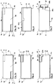
- FIG. 1a shows a sealing strip 1 according to the invention for sealing a joint 2 between a frame profile 3, for example, a window or door frame profile, and a wall 4, wherein the sealing region of the wall is usually the frame profile facing wall reveal 4a (see FIG. 6 ).
- the sealing strip 1 comprises a foam strip 6 which consists of an elastically compressible and resilient material, for example an open or closed-cell material.
- the foam strip 6 is resiliently retarded according to the embodiments of this invention, which area may extend only over one zone or the entire foam strip. This can generally be done so that the fully compressed foam strip will not go to its fully relaxed state until ⁇ 5 minutes or ⁇ 30 minutes after the compression force has been removed, but ⁇ 5-10 hours.
- a suitable impregnation for example a polymer dispersion such as an acrylate dispersion, latex dispersion or a wax, the average particle size is in the range of 1-10 microns.
- the foam strip may in this case be provided in regions or in whole (ie, preferably homogeneous) with such an impregnation.
- the sealing strip is in Fig. 1 in fully decompressed and deferred condition. Possibly.
- the impregnation 15 may also have a water vapor diffusion-braking effect.
- the sealing strip 1 has two opposite broad sides 1a, 1b, which in each case can be applied to the corresponding contact surfaces 3a, 4a of the frame profile 3 and wall 4. Transverse to these broad sides are narrow sides 1c, 1d of the sealing strip, which bridge the gap 2 and in the installed state of the sealing strip usually have a smaller width than the broadsides. In individual cases, however, the narrow sides may also have a greater width than the broad sides of the sealing strip (which may apply in the completely reset (decompressed) state of the sealing strip, in the installed state the ratio should be a maximum of 1: 1). This can generally apply in the context of the invention.
- the sealing strip 1 according to the invention further comprises an additional strip 7, which at least partially consists of a material with heavy fractions by which the sound insulation of the joint seal and also regardless of the handling of the sealing strip over conventional sealing strips are substantially improved.
- the additional strip 7 is formed in the sealing strip of the embodiments overlapping with the foam strip 6, which applies in particular in the installed state. This overlap can be seen in particular with regard to the extension of the sealing strip between the first and second broadside. When the sealing strip is arranged in the compressed state in the joint, the foam strip is thus at least partially compressed by the additional strip.
- the additional strip 7 is arranged in a channel or groove 6a of the foam strip 6, this groove being open toward the narrow side 1d (which, however, is not absolutely necessary), the additional strip 7 can also be arranged on the upper side of the foam strip 6.
- the additional strip 7 is attached to the foam strip, here by an adhesive layer 7a, for example, a self-adhesive layer.
- a suitable fastening means 8b is arranged on the broad side 1b, here in the form of an adhesive layer, in particular a self-adhesive layer.
- the adhesive layers can generally be covered within the scope of the invention with a peelable protective film (not shown).
- the sealing strip can be fastened or at least adhered to at least one or both of the bearing surfaces of the frame and wall, so that the sealing strip can be arranged securely in the joint and a proper and long-lasting assembly of the sealing strip is ensured despite the comparatively high weight of the additional strip.
- the additional strip consists according to the embodiment of a plastic material such as PVC with a mineral or metallic filler, in particular barium sulfate.
- the filler is distributed in the matrix of the additional strip, more precisely distributed homogeneously arranged.
- the additional strip has a specific gravity of about 2 g / cm 3 or at a thickness of about 3 mm, a basis weight of 6 kg / sqm, this has the additional strip a suitable proportion of heavy fillers, here barium sulfate in a proportion of about 30 to 40 wt .-% in the material of the additional strip.
- the additional strip further has according to the embodiment, a thickness of about 3 mm and a width of about 3 cm and has a rectangular cross section.
- the additional strip extends according to the example over a width of 25 to 50% of the width of the sealing strip, but this depends on the depth of the respective joint and thus the width of the sealing strip to be used.
- the additional strip has according to the embodiment, a weight per meter running of 150g.
- the additional strip has a share of about 50% of the total weight of the sealing strip, based on its installed state.
- the additional strip consists of a non-foamed, so solid material.
- the additional strip is independent of this from a little rigid material, whereby the sealing strip is rolled up in the longitudinal direction, in particular under compression of the foam material, and when rolling of the sealing strip, this due to the weight of the additional strip slightly on the contact surface, usually the contact surface of the frame profile, adapts (the provided with sealing strip frame can then be inserted on the wall or in the wall opening and fixed in this). Nevertheless, the bending stiffness of the additional strip is many times higher than that of the foam material of the sealing strip.
- the sealing strip 1 may comprise a further additional strip 9, which contains no heavy material fractions and, for example, is provided for producing an (additional) water vapor diffusion barrier or for other ticks.
- the further additional strip may also consist of a foam material, also from the material of the foam strip itself.
- FIG. 1b shows a modification of the embodiment according to FIG. 1a , wherein the fastening means 8b, preferably in the form of an adhesive layer, in particular in the form of a self-adhesive layer, is disposed on the broadside of the sealing strip facing away from the additional strip 7, ie the upper broad side in the figure.
- the fastening means 8b preferably in the form of an adhesive layer, in particular in the form of a self-adhesive layer, is disposed on the broadside of the sealing strip facing away from the additional strip 7, ie the upper broad side in the figure.
- this results in handling advantages, for example, if the additional strip is to be arranged on the side facing away from the frame profile.
- FIG. 2 shows a sealing strip accordingly FIG. 1 , wherein the modification consists in that the adhesive layer 18a, in particular self-adhesive layer, is additionally arranged on the broad side 1a with the additional strip 7.
- the adhesive layer 18a extends as shown only over the width of the additional strip 7, but may also extend laterally beyond.
- the adhesive layer or another fastening means for the corresponding contact surface can also be provided only on one broad side (the broad side 1a or 1b) or on both broad sides 1a, 1b.
- the adhesive layer 18a is only optional here.
- the fastening means may also extend (optionally only) over the additional strip at the corresponding broad side (as shown here, see adhesive layer 18a). Incidentally, the full content of the statements of FIG. 1 directed.
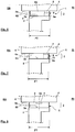
- FIG. 3 shows a modification of the sealing strip after FIG. 1 , wherein the modification is in a different profile design of the additional strip 27, for the rest, be full on the comments FIG. 1 directed.
- the additional strip 27 extends beyond its body 27a beyond the narrow side 1c, for which purpose the additional strip has a flank 27b arranged on the narrow side 1d.
- the additional strip is thereby formed substantially L-shaped.
- the additional strip thus extends over a greater part of the height of the sealing strip, especially in the installed state thereof, so that an improved sound insulation is given, and at the same time an increased water vapor diffusion resistance in the region of the additional strip, or with a corresponding arrangement of the sealing strip on the inside of the room the seal.
- the additional strip may be relatively flat.
- FIG. 4 shows a further modification of the additional strip 37 after FIG. 1 , moreover, the remarks to FIG. 1 is referenced.
- the additional strip 37 extends over the entire width of the sealing strip 1, resulting in a further improved sound insulation.
- the additional strip has a region 37b which projects toward the interior of the foam strip 6 and forms a cross-sectional narrowing of the foam strip 6, thereby further improving the sound insulation. If the projecting region 37b is arranged eccentrically, preferably in the region of a narrow side, this can at the same time serve to produce a water vapor diffusion gradient, so that the sealing strip is more diffusion-tight inside than in the installed state. It is understood that in this case the additional strip 37 does not have to extend over the entire width of the sealing strip, for example according to the FIGS. 1, 2 ,
- the adhesive layer 8a may extend over the entire width of the additional strip.
- FIG. 5 shows a further modification of the sealing strip 1 according to the invention, in which the additional strip 47 is secured by means of a profile strip 48 on the foam strip.
- the profile strip 48 may be suitably connected to the foam strip 6 in a form-fitting and / or cohesive manner, for example comprising an anchoring projection 48a, which protrudes into the foam strip, for example by engaging behind an undercut of the foam strip.
- the profile strip 48 may be glued to the foam strip 6.
- the additional strip 7 is attached by suitable means to the profile strip 48, for example, glued to this or fixed in a clamping seat on a mounting profile 48b thereof.
- In order to allow greater compression of the sealing tape in the installed state of the additional strip 47 and profile strip 48 may have a lower height.
- FIGS. 6 to 8 show arrangements according to the invention sealing strip in the joint between the frame profile and wall starting from a sealing strip FIG. 1 , it goes without saying corresponding apply to the other sealing strip according to the invention, in particular the embodiments. It is further understood that these representations also apply to the arrangement of the sealing strip 1 on the frame profile, ie independent of the arrangement of the wall. This may apply, for example, when the sealing strip is preassembled on the frame profile in order to be inserted into the associated wall opening.
- the sealing strip extends at least substantially over the entire frame width FT, thus representing both a seal to the interior of the room RI and the space outside RA.
- the arrangement of further sealing means for sealing the gap is thereby unnecessary.
- the sealing strip may also have a smaller width with respect to the respective frame width, thus, for example, only a space inside and / or only a space outside seal results, optionally also with formation of a seal in the middle region of the joint, then below Use of other sealing agents.
- the sealing strip can in each case be adapted to the general requirements, for example for the outer space-side sealing by a suitable means 62 such as a film, a coating or impregnation reinforced water repellent or impact rainproof be formed.
- the sealing strip on the inside of the room may have an increased water vapor diffusion resistance with respect to the middle or space outside region of the sealing strip, for example by arranging the additional strip 7 but alternatively or additionally by other means, for example a diffusion-inhibiting impregnation, coating, etc.
- FIG. 6 shows an arrangement of a sealing strip 1 after Fig. 1 in a joint 2 between the frame profile 3 and wall 4, wherein the sealing strip is arranged compressed between the contact surfaces 3a, 4a of the frame profile and wall.
- the additional strip 7 serves to improve the sound insulation.
- the additional strip 7 is in this case arranged outside the room RA, RI indicates the room inside.
- the additional strip 7 abuts against the contact surface of the frame profile 3, optionally, the sealing strip may also be arranged in the joint, that the additional strip 7 of the wall 4 or soffit is facing.
- Another additional strip 9, which must contain no heavy matter shares but may contain here covers the foam strip 6, so that the area 6a of the foam strip 6 is compressed more at the level of the additional strip 9, as the adjoining this space outside area 6b of the foam strip, and thereby at the same time has a higher water vapor diffusion resistance than the region 6b and acts as a water vapor diffusion brake.
- the sealing strip can be fastened or adhered to the contact surface 3a of the frame profile and / or the abutment surface 4a of the wall with a fastening means, for example a suitable profiling or an adhesive layer, in particular self-adhesive layer, and possibly abut the respective abutment surface except for the fastening means.
- FIG. 7 shows an alternative arrangement of the sealing strip FIG. 6
- the additional strip according to the invention comprising heavy-material fractions is arranged on the outside of the space, here facing the frame profile 3 (although in certain cases an orientation towards the wall may also be present).
- An attachment of the sealing strip relative to the frame profile 3 can also be done here by suitable fastening means, as described.
- the sealing strip can also be connected here in particular with the contact surface of the wall by a self-adhesive layer.
- the self-adhesive layer on the broad side 1a (facing the frame profile) may extend over the additional strip, possibly only over this.
- the additional strip 7 here covers the foam strip 6, so that the area of the foam strip 6a at the level of the additional strip 7 is more compressed than the adjoining space outside area 6b, and thereby at the same time has a higher water vapor diffusion resistance and acts as a water vapor diffusion brake. At the same time, the additional strip 7 serves the sound insulation.
- a vapor diffusion brake or barrier 71 may be provided on the inner narrow side 1c, for example by means of a suitable foil, impregnation or coating.
- FIG. 8 shows a further modification of the sealing strip according to the invention, wherein the additional strip 7 is arranged in the central region of the foam strip 6.
- the additional strip 7 is here arranged centrally on the foam strip.
- the additional strip for generating a water vapor diffusion gradient is displaced off-center with respect to the center plane 82 of the sealing strip, in particular towards the interior side, so that the sealing strip in the assembled state is denser inside than in relation to a vapor diffusion resistance.
Landscapes
- Engineering & Computer Science (AREA)
- Civil Engineering (AREA)
- Structural Engineering (AREA)
- Building Environments (AREA)
Priority Applications (1)
| Application Number | Priority Date | Filing Date | Title |
|---|---|---|---|
| PL12161525T PL2514902T3 (pl) | 2011-04-19 | 2012-03-27 | Taśma uszczelniająca |
Applications Claiming Priority (1)
| Application Number | Priority Date | Filing Date | Title |
|---|---|---|---|
| DE202011005415U DE202011005415U1 (de) | 2011-04-19 | 2011-04-19 | Dichtstreifen |
Publications (3)
| Publication Number | Publication Date |
|---|---|
| EP2514902A2 EP2514902A2 (de) | 2012-10-24 |
| EP2514902A3 EP2514902A3 (de) | 2015-06-24 |
| EP2514902B1 true EP2514902B1 (de) | 2017-10-18 |
Family
ID=45954404
Family Applications (1)
| Application Number | Title | Priority Date | Filing Date |
|---|---|---|---|
| EP12161525.6A Not-in-force EP2514902B1 (de) | 2011-04-19 | 2012-03-27 | Dichtstreifen |
Country Status (3)
| Country | Link |
|---|---|
| EP (1) | EP2514902B1 (pl) |
| DE (1) | DE202011005415U1 (pl) |
| PL (1) | PL2514902T3 (pl) |
Families Citing this family (4)
| Publication number | Priority date | Publication date | Assignee | Title |
|---|---|---|---|---|
| DE102016110665A1 (de) | 2016-06-09 | 2017-12-14 | Odenwald-Chemie Gmbh | Verbundelement |
| EP3540166B1 (de) | 2018-03-16 | 2025-02-26 | Silu Verwaltung AG | Dichtstreifen |
| PL3839187T3 (pl) * | 2019-12-18 | 2024-07-01 | Iso-Chemie Gmbh | Fragment budynku z taśmą uszczelniającą |
| EP3878619B1 (de) * | 2020-03-13 | 2025-07-02 | Hanno-Werk GmbH & Co. KG | Verfahren zum partiellen imprägnieren eines schaumstoffs |
Family Cites Families (3)
| Publication number | Priority date | Publication date | Assignee | Title |
|---|---|---|---|---|
| DE20009674U1 (de) * | 1999-06-09 | 2000-09-14 | Hanno-Werk GmbH & Co. KG, 30880 Laatzen | Mehrlagiges Dichtungsband zum Abdichten von Fugen |
| EP1801111B1 (en) | 2005-12-20 | 2014-07-16 | LEK Pharmaceuticals d.d. | Novel polymorph forms of olmesartan medoxomil |
| DE102006043050A1 (de) | 2006-01-19 | 2007-07-26 | Tremco Illbruck Produktion Gmbh | Zur Abdichtung eines Fensterrahmens geeigneter Schaumstoff-Dichtstreifen sowie zum Einbau vorbereiteter Fensterrahmen |
-
2011
- 2011-04-19 DE DE202011005415U patent/DE202011005415U1/de not_active Expired - Lifetime
-
2012
- 2012-03-27 PL PL12161525T patent/PL2514902T3/pl unknown
- 2012-03-27 EP EP12161525.6A patent/EP2514902B1/de not_active Not-in-force
Non-Patent Citations (1)
| Title |
|---|
| None * |
Also Published As
| Publication number | Publication date |
|---|---|
| PL2514902T3 (pl) | 2018-03-30 |
| EP2514902A2 (de) | 2012-10-24 |
| DE202011005415U1 (de) | 2012-07-20 |
| EP2514902A3 (de) | 2015-06-24 |
Similar Documents
| Publication | Publication Date | Title |
|---|---|---|
| EP3256660B1 (de) | Fugendichtungselement und dichtanordnung mit derartigem fugendichtungselement | |
| EP1811111B1 (de) | Fensterlaibung mit einem Fensterrahmen und einem Dichtstreifen | |
| EP1808565B1 (de) | Abdichtungsanordnung und Profilleiste für eine Abdichtungsanordnung | |
| EP3256663B1 (de) | Fugendichtband mit vorbestimmter geometrie und dichtanordnung mit derartigem fugendichtband | |
| WO2016128536A1 (de) | Fugendichtband und dichtanordnung mit derartigem dichtband | |
| DE202012104826U1 (de) | Dichtband mit Funktionsstreifen | |
| EP2514902B1 (de) | Dichtstreifen | |
| EP1947280B1 (de) | Profilanschlussleiste für einen übergang von einem bauteil zu einer gebäudewand | |
| DE202011005416U1 (de) | Dichtstreifen | |
| AT516184B1 (de) | Anschlussprofil für an Putz angrenzende Bauteile | |
| DE102015202882B4 (de) | Dichtungsband und Dichtungsanordnung | |
| EP2762668B1 (de) | Anschlussprofil | |
| DE202012007697U1 (de) | Anputzleiste, Abschlussschiene und Putz-Eckleiste | |
| EP2836662B1 (de) | Dichtsystem zwischen einem fensterrahmen und einer wand eines gebäudes | |
| EP0877143A2 (de) | Strangdichtung | |
| EP3115539B1 (de) | Bauwerksbereich mit dichtband | |
| AT528000B1 (de) | Anschlussprofil für an putz angrenzende bauteile mit dichtschlaufe | |
| AT513757B1 (de) | Anschlussprofil | |
| EP2899354B1 (de) | Vorwandmontagesystem für teilauskragende bauelemente und wandaufbau mit vorwandmontagesystem | |
| EP3256665A1 (de) | Fugendichtband und dichtanordnung mit derartigem dichtband | |
| DE102015202873B4 (de) | Dichtungsband und Dichtungsanordnung | |
| EP1819888A1 (de) | Dämmstoffelement aus mineralfasern und wärmedämmverbundsystem zur wärme- und/oder schalldämmung und/oder zum brandschutz einer gebäudeaussenwand | |
| DE202012012930U1 (de) | Dämmelemente für geschraubte Fassadenkonstruktionen sowie Fassadenkonstruktion | |
| HK1242753B (en) | Sealing tape with predetermined geometry and sealing assembly comprising such a sealing tape | |
| DE202014105657U1 (de) | Anschlusselement |
Legal Events
| Date | Code | Title | Description |
|---|---|---|---|
| PUAI | Public reference made under article 153(3) epc to a published international application that has entered the european phase |
Free format text: ORIGINAL CODE: 0009012 |
|
| AK | Designated contracting states |
Kind code of ref document: A2 Designated state(s): AL AT BE BG CH CY CZ DE DK EE ES FI FR GB GR HR HU IE IS IT LI LT LU LV MC MK MT NL NO PL PT RO RS SE SI SK SM TR |
|
| AX | Request for extension of the european patent |
Extension state: BA ME |
|
| PUAL | Search report despatched |
Free format text: ORIGINAL CODE: 0009013 |
|
| AK | Designated contracting states |
Kind code of ref document: A3 Designated state(s): AL AT BE BG CH CY CZ DE DK EE ES FI FR GB GR HR HU IE IS IT LI LT LU LV MC MK MT NL NO PL PT RO RS SE SI SK SM TR |
|
| AX | Request for extension of the european patent |
Extension state: BA ME |
|
| RIC1 | Information provided on ipc code assigned before grant |
Ipc: E06B 1/64 20060101ALI20150518BHEP Ipc: E06B 1/62 20060101AFI20150518BHEP |
|
| 17P | Request for examination filed |
Effective date: 20151001 |
|
| RBV | Designated contracting states (corrected) |
Designated state(s): AL AT BE BG CH CY CZ DE DK EE ES FI FR GB GR HR HU IE IS IT LI LT LU LV MC MK MT NL NO PL PT RO RS SE SI SK SM TR |
|
| GRAP | Despatch of communication of intention to grant a patent |
Free format text: ORIGINAL CODE: EPIDOSNIGR1 |
|
| INTG | Intention to grant announced |
Effective date: 20170428 |
|
| GRAS | Grant fee paid |
Free format text: ORIGINAL CODE: EPIDOSNIGR3 |
|
| GRAA | (expected) grant |
Free format text: ORIGINAL CODE: 0009210 |
|
| RIN1 | Information on inventor provided before grant (corrected) |
Inventor name: NAUCK, HELMAR Inventor name: ANDEXER, DENNIS Inventor name: KOMMA, MARKUS |
|
| AK | Designated contracting states |
Kind code of ref document: B1 Designated state(s): AL AT BE BG CH CY CZ DE DK EE ES FI FR GB GR HR HU IE IS IT LI LT LU LV MC MK MT NL NO PL PT RO RS SE SI SK SM TR |
|
| REG | Reference to a national code |
Ref country code: GB Ref legal event code: FG4D Free format text: NOT ENGLISH |
|
| REG | Reference to a national code |
Ref country code: CH Ref legal event code: EP Ref country code: CH Ref legal event code: NV Representative=s name: ROTTMANN, ZIMMERMANN + PARTNER AG, CH |
|
| REG | Reference to a national code |
Ref country code: AT Ref legal event code: REF Ref document number: 938112 Country of ref document: AT Kind code of ref document: T Effective date: 20171115 Ref country code: IE Ref legal event code: FG4D Free format text: LANGUAGE OF EP DOCUMENT: GERMAN |
|
| REG | Reference to a national code |
Ref country code: DE Ref legal event code: R096 Ref document number: 502012011460 Country of ref document: DE |
|
| REG | Reference to a national code |
Ref country code: NL Ref legal event code: MP Effective date: 20171018 |
|
| REG | Reference to a national code |
Ref country code: LT Ref legal event code: MG4D |
|
| REG | Reference to a national code |
Ref country code: FR Ref legal event code: PLFP Year of fee payment: 7 |
|
| PG25 | Lapsed in a contracting state [announced via postgrant information from national office to epo] |
Ref country code: NL Free format text: LAPSE BECAUSE OF FAILURE TO SUBMIT A TRANSLATION OF THE DESCRIPTION OR TO PAY THE FEE WITHIN THE PRESCRIBED TIME-LIMIT Effective date: 20171018 |
|
| PG25 | Lapsed in a contracting state [announced via postgrant information from national office to epo] |
Ref country code: SE Free format text: LAPSE BECAUSE OF FAILURE TO SUBMIT A TRANSLATION OF THE DESCRIPTION OR TO PAY THE FEE WITHIN THE PRESCRIBED TIME-LIMIT Effective date: 20171018 Ref country code: LT Free format text: LAPSE BECAUSE OF FAILURE TO SUBMIT A TRANSLATION OF THE DESCRIPTION OR TO PAY THE FEE WITHIN THE PRESCRIBED TIME-LIMIT Effective date: 20171018 Ref country code: NO Free format text: LAPSE BECAUSE OF FAILURE TO SUBMIT A TRANSLATION OF THE DESCRIPTION OR TO PAY THE FEE WITHIN THE PRESCRIBED TIME-LIMIT Effective date: 20180118 Ref country code: FI Free format text: LAPSE BECAUSE OF FAILURE TO SUBMIT A TRANSLATION OF THE DESCRIPTION OR TO PAY THE FEE WITHIN THE PRESCRIBED TIME-LIMIT Effective date: 20171018 Ref country code: ES Free format text: LAPSE BECAUSE OF FAILURE TO SUBMIT A TRANSLATION OF THE DESCRIPTION OR TO PAY THE FEE WITHIN THE PRESCRIBED TIME-LIMIT Effective date: 20171018 |
|
| PG25 | Lapsed in a contracting state [announced via postgrant information from national office to epo] |
Ref country code: HR Free format text: LAPSE BECAUSE OF FAILURE TO SUBMIT A TRANSLATION OF THE DESCRIPTION OR TO PAY THE FEE WITHIN THE PRESCRIBED TIME-LIMIT Effective date: 20171018 Ref country code: GR Free format text: LAPSE BECAUSE OF FAILURE TO SUBMIT A TRANSLATION OF THE DESCRIPTION OR TO PAY THE FEE WITHIN THE PRESCRIBED TIME-LIMIT Effective date: 20180119 Ref country code: IS Free format text: LAPSE BECAUSE OF FAILURE TO SUBMIT A TRANSLATION OF THE DESCRIPTION OR TO PAY THE FEE WITHIN THE PRESCRIBED TIME-LIMIT Effective date: 20180218 Ref country code: RS Free format text: LAPSE BECAUSE OF FAILURE TO SUBMIT A TRANSLATION OF THE DESCRIPTION OR TO PAY THE FEE WITHIN THE PRESCRIBED TIME-LIMIT Effective date: 20171018 Ref country code: BG Free format text: LAPSE BECAUSE OF FAILURE TO SUBMIT A TRANSLATION OF THE DESCRIPTION OR TO PAY THE FEE WITHIN THE PRESCRIBED TIME-LIMIT Effective date: 20180118 Ref country code: LV Free format text: LAPSE BECAUSE OF FAILURE TO SUBMIT A TRANSLATION OF THE DESCRIPTION OR TO PAY THE FEE WITHIN THE PRESCRIBED TIME-LIMIT Effective date: 20171018 |
|
| REG | Reference to a national code |
Ref country code: DE Ref legal event code: R097 Ref document number: 502012011460 Country of ref document: DE |
|
| PG25 | Lapsed in a contracting state [announced via postgrant information from national office to epo] |
Ref country code: SK Free format text: LAPSE BECAUSE OF FAILURE TO SUBMIT A TRANSLATION OF THE DESCRIPTION OR TO PAY THE FEE WITHIN THE PRESCRIBED TIME-LIMIT Effective date: 20171018 Ref country code: DK Free format text: LAPSE BECAUSE OF FAILURE TO SUBMIT A TRANSLATION OF THE DESCRIPTION OR TO PAY THE FEE WITHIN THE PRESCRIBED TIME-LIMIT Effective date: 20171018 Ref country code: CZ Free format text: LAPSE BECAUSE OF FAILURE TO SUBMIT A TRANSLATION OF THE DESCRIPTION OR TO PAY THE FEE WITHIN THE PRESCRIBED TIME-LIMIT Effective date: 20171018 Ref country code: EE Free format text: LAPSE BECAUSE OF FAILURE TO SUBMIT A TRANSLATION OF THE DESCRIPTION OR TO PAY THE FEE WITHIN THE PRESCRIBED TIME-LIMIT Effective date: 20171018 |
|
| PLBE | No opposition filed within time limit |
Free format text: ORIGINAL CODE: 0009261 |
|
| STAA | Information on the status of an ep patent application or granted ep patent |
Free format text: STATUS: NO OPPOSITION FILED WITHIN TIME LIMIT |
|
| PG25 | Lapsed in a contracting state [announced via postgrant information from national office to epo] |
Ref country code: SM Free format text: LAPSE BECAUSE OF FAILURE TO SUBMIT A TRANSLATION OF THE DESCRIPTION OR TO PAY THE FEE WITHIN THE PRESCRIBED TIME-LIMIT Effective date: 20171018 Ref country code: IT Free format text: LAPSE BECAUSE OF FAILURE TO SUBMIT A TRANSLATION OF THE DESCRIPTION OR TO PAY THE FEE WITHIN THE PRESCRIBED TIME-LIMIT Effective date: 20171018 Ref country code: RO Free format text: LAPSE BECAUSE OF FAILURE TO SUBMIT A TRANSLATION OF THE DESCRIPTION OR TO PAY THE FEE WITHIN THE PRESCRIBED TIME-LIMIT Effective date: 20171018 |
|
| REG | Reference to a national code |
Ref country code: DE Ref legal event code: R081 Ref document number: 502012011460 Country of ref document: DE Owner name: TREMCO CPG GERMANY GMBH, DE Free format text: FORMER OWNER: TREMCO ILLBRUCK PRODUKTION GMBH, 92439 BODENWOEHR, DE Ref country code: DE Ref legal event code: R082 Ref document number: 502012011460 Country of ref document: DE Representative=s name: HANNKE BITTNER & PARTNER, PATENT- UND RECHTSAN, DE Ref country code: DE Ref legal event code: R081 Ref document number: 502012011460 Country of ref document: DE Owner name: TREMCO ILLBRUCK GMBH, DE Free format text: FORMER OWNER: TREMCO ILLBRUCK PRODUKTION GMBH, 92439 BODENWOEHR, DE |
|
| 26N | No opposition filed |
Effective date: 20180719 |
|
| PG25 | Lapsed in a contracting state [announced via postgrant information from national office to epo] |
Ref country code: MT Free format text: LAPSE BECAUSE OF FAILURE TO SUBMIT A TRANSLATION OF THE DESCRIPTION OR TO PAY THE FEE WITHIN THE PRESCRIBED TIME-LIMIT Effective date: 20171018 |
|
| PG25 | Lapsed in a contracting state [announced via postgrant information from national office to epo] |
Ref country code: SI Free format text: LAPSE BECAUSE OF FAILURE TO SUBMIT A TRANSLATION OF THE DESCRIPTION OR TO PAY THE FEE WITHIN THE PRESCRIBED TIME-LIMIT Effective date: 20171018 Ref country code: MC Free format text: LAPSE BECAUSE OF FAILURE TO SUBMIT A TRANSLATION OF THE DESCRIPTION OR TO PAY THE FEE WITHIN THE PRESCRIBED TIME-LIMIT Effective date: 20171018 |
|
| REG | Reference to a national code |
Ref country code: BE Ref legal event code: MM Effective date: 20180331 |
|
| REG | Reference to a national code |
Ref country code: IE Ref legal event code: MM4A |
|
| PG25 | Lapsed in a contracting state [announced via postgrant information from national office to epo] |
Ref country code: LU Free format text: LAPSE BECAUSE OF NON-PAYMENT OF DUE FEES Effective date: 20180327 |
|
| PG25 | Lapsed in a contracting state [announced via postgrant information from national office to epo] |
Ref country code: IE Free format text: LAPSE BECAUSE OF NON-PAYMENT OF DUE FEES Effective date: 20180327 |
|
| PG25 | Lapsed in a contracting state [announced via postgrant information from national office to epo] |
Ref country code: BE Free format text: LAPSE BECAUSE OF NON-PAYMENT OF DUE FEES Effective date: 20180331 |
|
| PGFP | Annual fee paid to national office [announced via postgrant information from national office to epo] |
Ref country code: NL Payment date: 20190121 Year of fee payment: 15 Ref country code: FR Payment date: 20190326 Year of fee payment: 8 Ref country code: GB Payment date: 20190325 Year of fee payment: 8 Ref country code: CH Payment date: 20190325 Year of fee payment: 8 |
|
| PGFP | Annual fee paid to national office [announced via postgrant information from national office to epo] |
Ref country code: AT Payment date: 20190319 Year of fee payment: 8 |
|
| PG25 | Lapsed in a contracting state [announced via postgrant information from national office to epo] |
Ref country code: TR Free format text: LAPSE BECAUSE OF FAILURE TO SUBMIT A TRANSLATION OF THE DESCRIPTION OR TO PAY THE FEE WITHIN THE PRESCRIBED TIME-LIMIT Effective date: 20171018 |
|
| PGFP | Annual fee paid to national office [announced via postgrant information from national office to epo] |
Ref country code: DE Payment date: 20200309 Year of fee payment: 9 |
|
| PG25 | Lapsed in a contracting state [announced via postgrant information from national office to epo] |
Ref country code: HU Free format text: LAPSE BECAUSE OF FAILURE TO SUBMIT A TRANSLATION OF THE DESCRIPTION OR TO PAY THE FEE WITHIN THE PRESCRIBED TIME-LIMIT; INVALID AB INITIO Effective date: 20120327 Ref country code: PT Free format text: LAPSE BECAUSE OF FAILURE TO SUBMIT A TRANSLATION OF THE DESCRIPTION OR TO PAY THE FEE WITHIN THE PRESCRIBED TIME-LIMIT Effective date: 20171018 |
|
| PG25 | Lapsed in a contracting state [announced via postgrant information from national office to epo] |
Ref country code: CY Free format text: LAPSE BECAUSE OF FAILURE TO SUBMIT A TRANSLATION OF THE DESCRIPTION OR TO PAY THE FEE WITHIN THE PRESCRIBED TIME-LIMIT Effective date: 20171018 Ref country code: MK Free format text: LAPSE BECAUSE OF NON-PAYMENT OF DUE FEES Effective date: 20171018 |
|
| PG25 | Lapsed in a contracting state [announced via postgrant information from national office to epo] |
Ref country code: AL Free format text: LAPSE BECAUSE OF FAILURE TO SUBMIT A TRANSLATION OF THE DESCRIPTION OR TO PAY THE FEE WITHIN THE PRESCRIBED TIME-LIMIT Effective date: 20171018 |
|
| REG | Reference to a national code |
Ref country code: DE Ref legal event code: R082 Ref document number: 502012011460 Country of ref document: DE Representative=s name: HANNKE BITTNER & PARTNER, PATENT- UND RECHTSAN, DE Ref country code: DE Ref legal event code: R081 Ref document number: 502012011460 Country of ref document: DE Owner name: TREMCO CPG GERMANY GMBH, DE Free format text: FORMER OWNER: TREMCO ILLBRUCK GMBH, 92439 BODENWOEHR, DE |
|
| REG | Reference to a national code |
Ref country code: CH Ref legal event code: PL |
|
| REG | Reference to a national code |
Ref country code: AT Ref legal event code: MM01 Ref document number: 938112 Country of ref document: AT Kind code of ref document: T Effective date: 20200327 |
|
| PG25 | Lapsed in a contracting state [announced via postgrant information from national office to epo] |
Ref country code: FR Free format text: LAPSE BECAUSE OF NON-PAYMENT OF DUE FEES Effective date: 20200331 Ref country code: CH Free format text: LAPSE BECAUSE OF NON-PAYMENT OF DUE FEES Effective date: 20200331 Ref country code: LI Free format text: LAPSE BECAUSE OF NON-PAYMENT OF DUE FEES Effective date: 20200331 Ref country code: AT Free format text: LAPSE BECAUSE OF NON-PAYMENT OF DUE FEES Effective date: 20200327 |
|
| GBPC | Gb: european patent ceased through non-payment of renewal fee |
Effective date: 20200327 |
|
| PG25 | Lapsed in a contracting state [announced via postgrant information from national office to epo] |
Ref country code: GB Free format text: LAPSE BECAUSE OF NON-PAYMENT OF DUE FEES Effective date: 20200327 |
|
| REG | Reference to a national code |
Ref country code: DE Ref legal event code: R119 Ref document number: 502012011460 Country of ref document: DE |
|
| PG25 | Lapsed in a contracting state [announced via postgrant information from national office to epo] |
Ref country code: DE Free format text: LAPSE BECAUSE OF NON-PAYMENT OF DUE FEES Effective date: 20211001 |
|
| PG25 | Lapsed in a contracting state [announced via postgrant information from national office to epo] |
Ref country code: PL Free format text: LAPSE BECAUSE OF NON-PAYMENT OF DUE FEES Effective date: 20200327 |