EP2514349B1 - Wascheimer mit einer Rolle - Google Patents
Wascheimer mit einer Rolle Download PDFInfo
- Publication number
- EP2514349B1 EP2514349B1 EP12165119.4A EP12165119A EP2514349B1 EP 2514349 B1 EP2514349 B1 EP 2514349B1 EP 12165119 A EP12165119 A EP 12165119A EP 2514349 B1 EP2514349 B1 EP 2514349B1
- Authority
- EP
- European Patent Office
- Prior art keywords
- shell
- roller
- wash bucket
- roller according
- clip connection
- Prior art date
- Legal status (The legal status is an assumption and is not a legal conclusion. Google has not performed a legal analysis and makes no representation as to the accuracy of the status listed.)
- Active
Links
Images
Classifications
-
- E—FIXED CONSTRUCTIONS
- E04—BUILDING
- E04F—FINISHING WORK ON BUILDINGS, e.g. STAIRS, FLOORS
- E04F21/00—Implements for finishing work on buildings
- E04F21/02—Implements for finishing work on buildings for applying plasticised masses to surfaces, e.g. plastering walls
- E04F21/06—Implements for applying plaster, insulating material, or the like
-
- A—HUMAN NECESSITIES
- A47—FURNITURE; DOMESTIC ARTICLES OR APPLIANCES; COFFEE MILLS; SPICE MILLS; SUCTION CLEANERS IN GENERAL
- A47L—DOMESTIC WASHING OR CLEANING; SUCTION CLEANERS IN GENERAL
- A47L13/00—Implements for cleaning floors, carpets, furniture, walls, or wall coverings
- A47L13/10—Scrubbing; Scouring; Cleaning; Polishing
- A47L13/50—Auxiliary implements
- A47L13/58—Wringers for scouring pads, mops, or the like, combined with buckets
- A47L13/60—Wringers for scouring pads, mops, or the like, combined with buckets with squeezing rollers
-
- B—PERFORMING OPERATIONS; TRANSPORTING
- B08—CLEANING
- B08B—CLEANING IN GENERAL; PREVENTION OF FOULING IN GENERAL
- B08B1/00—Cleaning by methods involving the use of tools
- B08B1/10—Cleaning by methods involving the use of tools characterised by the type of cleaning tool
- B08B1/14—Wipes; Absorbent members, e.g. swabs or sponges
-
- B—PERFORMING OPERATIONS; TRANSPORTING
- B08—CLEANING
- B08B—CLEANING IN GENERAL; PREVENTION OF FOULING IN GENERAL
- B08B1/00—Cleaning by methods involving the use of tools
- B08B1/50—Cleaning by methods involving the use of tools involving cleaning of the cleaning members
- B08B1/54—Cleaning by methods involving the use of tools involving cleaning of the cleaning members using mechanical tools
Definitions
- the innovation relates to a washing bucket with a role for stripping a sponge board over the washing bucket.
- Such rolls are used by tilers as part of a tiling board tamping device consisting of a washing bucket, a sponge board and a roll.
- the tiler After inserting the joints, the tiler washes the tile covering off with a sponge board to remove any remaining cement. As a result, the sponge surface is inevitably heavily contaminated by the inclusion of the cement residues. To remove this cement veil from the sponge surface, the tiler dips the sponge board in a wash bucket with water and pushes the sponge board on the roll.
- the roller is designed as a hollow body and has a profiled lateral surface with a plurality of slot-shaped passage openings. Furthermore, the role consists of half-shells.
- the innovation is based on the task to offer an easy to produce and at the same time stable role.
- the reel according to the present invention for stripping a sponge board on a washing bucket which is rotatably mounted with an axle or stub axles in bearings on or on the edge of a Wascheimers and spans the clear width is formed as a hollow body and has a profiled lateral surface with a plurality of slot-shaped openings on. Furthermore, the roller consists of a first half-shell and of a second half-shell, which are connected to one another via a clip connection inextricably.
- the non-releasable clip connection allows both an easy to manufacture as well as a reliable connection of the two half-shells, which increases the stability of the role.
- a plurality of axially extending webs is present on the outer circumferential surface of the roller.
- the webs cause the stripping operation, i. expressing the sponge board on the roll, supported.
- the webs increase the stability of the roll.
- extending slot-shaped passage openings are arranged between the webs in the circumferential direction. Through the slot-shaped passage openings, the contaminated water, which is pressed out by the expressions of the sponge board on the roll from the sponge, quickly and largely unhindered flow through the trained as a hollow role in the washing bucket.
- the wiping action of the roller is additionally increased if the webs are distributed on the lateral surface in such a way that adjacent webs are arranged offset in the axial direction by a certain angle relative to one another. In this way, an alternating arrangement of webs and slot-shaped passage openings is achieved, resulting in an overall uniform stripping over the entire width of the roller.
- the non-detachable clip connection is formed by a plurality of pins, each of which engages in a corresponding with the respective pin recess.
- the pins may be formed on the first half-shell and the corresponding recesses on the second half-shell.
- At least one rod-shaped stiffening element is formed in the roller interior.
- a support element arranged in the roller interior which preferably extends in the radial direction, prevents bending of the roller designed as a hollow body. The stability of the roll is thus increased.
- the rod-shaped stiffening element is formed from two pins each formed on one of the half-shells, which pins are connected to one another by a plug-in, latching or clip connection.
- the rod-shaped reinforcing element forms a non-detachable clip connection with the first half-shell and the second half-shell.
- the stiffening element fulfills a double function: First, the rigidity of the roller is increased, for other, the connection strength between the first and second half-shells is improved.
- the storage of the role can be done both by a continuous roller axle and by stub axle, which can be made of metal or plastic, respectively.
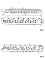
- Fig. 1 shows an exploded perspective view of the roller 1.
- the roller 1 consists of a first half-shell 2 and a second half-shell 3. Both half-shells 2, 3 are formed as a hollow body. On the lateral surfaces of the half-shells 2, 3 slot-shaped passage openings 4 are arranged. Furthermore, webs 5 on the lateral surfaces of Half shells 2, 3 available. The webs 5 run in the axial direction, ie in the direction of the main axis of the roller 1.
- the slot-shaped passage openings 4, however, are positioned on the lateral surfaces such that their long side in the circumferential direction, that is perpendicular to the longitudinal direction of the webs 5, runs. Furthermore, the webs 5 are distributed on the lateral surface of the first half-shell 2 or the second half-shell 3 in such a way that adjacent webs 5 are arranged offset in the axial direction by a certain angle relative to one another.
- the first half-shell 2 has a plurality of pins 6 (in Fig. 1 not shown), which together with the corresponding recesses 7 form a permanent clip connection.
- the corresponding recesses 7 are formed in the second half-shell 3 and have substantially the shape of a blind hole.
- the recesses 7 are distributed along the connecting surface of the two half-shells 2, 3.
- rod-shaped stiffening element are present inside the roller 1 .
- These rod-shaped stiffening elements are formed from pins 8, which each extend from the half-shells 2, 3 in the roller interior and can be connected to one another with a plug-in, latching or clip connection.
- the rod-shaped reinforcing element can form a non-detachable clip connection with the first half-shell 2 and the second half-shell 3.
- a stub axle 9 which can be rotatably mounted in a corresponding bearing of a washing bucket (not shown).
- a cover 10 At the ends of the half-shells 2, 3 are each closed by a cover 10, so that there can escape from the roll 1 no water.
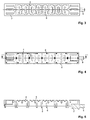
- Fig. 2 to Fig. 5 each show the first half-shell 2 from different perspectives.
- the first half-shell 2 has a profiled lateral surface with a multiplicity of slot-shaped passage openings 4 and axially extending webs 5. Further, the first half-shell 2 has a plurality of pins 6. These pins 6 are distributed along the connecting surface of the two half-shells 2, 3.
- the pins 6 together with the corresponding recesses 7 present on the first half-shell 2 form an inseparable clip connection.
- the pins 6 have a shape which makes it possible to introduce these inextricably in the recesses.
- the first half-shell 1 further has pins 8 which extend into the roller interior. Together with the located on the second half-shell 3 pins 8, these form the rod-shaped stiffening elements.
Landscapes
- Engineering & Computer Science (AREA)
- Architecture (AREA)
- Civil Engineering (AREA)
- Structural Engineering (AREA)
- Investigation Of Foundation Soil And Reinforcement Of Foundation Soil By Compacting Or Drainage (AREA)
- Cleaning In General (AREA)
- Clamps And Clips (AREA)
- Rollers For Roller Conveyors For Transfer (AREA)
Description
- Die Neuerung betrifft einen Wascheimer mit einer Rolle zum Abstreifen eines Schwammbretts über dem Wascheimer.
- Derartige Rollen werden als Bestandteil einer Ausdrückvorrichtung für Fliesenwaschbretter, die aus einem Wascheimer, einem Schwammbrett und einer Rolle besteht, von Fliesenlegern verwendet.
- Nach dem Einfugen der Fugen wäscht der Fliesenleger zum Entfernen von Zementresten den Fliesenbelag mit einem Schwammbrett ab. Dadurch wird der Schwammbelag durch die Aufnahme der Zementreste zwangsläufig stark verschmutzt. Um diesen Zementschleier wieder aus dem Schwammbelag zu entfernen, taucht der Fliesenleger das Schwammbrett in einen Wascheimer mit Wasser und drückt das Schwammbrett auf der Rolle aus.
- Dadurch wird das im Schwamm befindliche Wasser aus dem Schwamm herausgedrückt und der darin enthaltene Zement bzw. die darin enthaltene Fugenmasse sammelt sich im Wasser des Fliesen-Wascheimers.
- Eine derartige als Hohlkörper ausgebildete Rolle zum Abstreifen eines Schwammbretts über einem Wascheimer, die mit einer Achse oder Achsstummeln in Lagern drehbar an oder auf dem Rand eines Wascheimers gelagert ist und dessen lichte Weite überspannt, ist beispielsweise aus
DE 35 02 307 C2 bekannt.EP 2 098 306 A2 beschreibt eine Rolle, die aus zwei Halbschalen gebildet wird. -
DE 201 02 362 U1 beschreibt einen Wascheimer mit einer Rolle zum Abstreifen eines Schwammbretts. Die Rolle ist als Hohlkörper ausgebildet und weist eine profilierte Mantelfläche mit einer Vielzahl von langlochförmigen Durchtrittsöffnungen auf. Ferner besteht die Rolle aus Halbschalen. - Der Neuerung liegt die Aufgabe zugrunde, eine einfach zu fertigende und zugleich stabile Rolle anzubieten.
- Diese Aufgabe wird durch die Merkmale des Schutzanspruchs 1 gelöst. Vorteilhafte Ausführungsformen sind in den Unteransprüchen beschrieben.
- Die neuerungsgemäße Rolle zum Abstreifen eines Schwammbretts über einem Wascheimer, die mit einer Achse oder Achsstummeln in Lagern drehbar an oder auf dem Rand eines Wascheimers gelagert ist und dessen lichte Weite überspannt, ist als Hohlkörper ausgebildet und weist eine profilierte Mantelfläche mit einer Vielzahl von langlochförmigen Durchtrittsöffnungen auf. Ferner besteht die Rolle aus einer ersten Halbschale und aus einer zweiten Halbschale, welche über eine Klippverbindung unlösbar miteinander verbunden sind.
- Durch den Aufbau der Rolle aus zwei Halbschalen ist eine einfache Fertigung möglich. Daneben ermöglicht die unlösbare Klippverbindung sowohl eine einfach zu fertigende als auch eine zuverlässige Verbindung der beiden Halbschalen, was die Stabilität der Rolle erhöht.
- In vorteilhafte Weise ist auf der äußeren Mantelfläche der Rolle eine Vielzahl von axial verlaufenden Stegen vorhanden. Durch die Stege wird der Abstreifvorgang, d.h. das Ausdrücken des Schwammbretts auf der Rolle, unterstützt. Gleichzeitig erhöhen die Stege die Stabilität der Rolle.
- In einer vorteilhaften Ausführungsform sind zwischen den Stegen in Umfangsrichtung verlaufende langlochförmige Durchtrittsöffnungen angeordnet. Durch die langlochförmigen Durchtrittsöffnungen kann das verschmutzte Wasser, das durch das Ausdrücken des Schwammbretts auf der Rolle aus dem Schwamm herausgepresst wird, schnell und weitgehend ungehindert durch die als Hohlkörper ausgebildete Rolle in den Wascheimer fließen.
- Die Abstreifwirkung der Rolle wird zusätzlich erhöht, wenn die Stege derart auf der Mantelfläche verteilt sind, dass in axialer Richtung benachbarte Stege um einen bestimmten Winkel versetzt zueinander angeordnet sind. Auf diese Weise wird eine alternierende Anordnung von Stegen und langlochförmigen Durchtrittsöffnungen erzielt, was insgesamt zu einem gleichförmigen Abstreifvorgang über die gesamte Breite der Rolle führt.
- In vorteilhafter Weise wird die unlösbare Klippverbindung durch eine Vielzahl von Zapfen, die jeweils in eine mit den jeweiligen Zapfen korrespondierende Aufnehmung eingreifen, gebildet. Durch ein unlösbares Einklippen der Zapfen in entsprechende Aufnehmungen wird eine besonders zuverlässige Verbindung zwischen den beiden Halbschalen errreicht. Hierbei können die Zapfen auf der ersten Halbschale und die korrespondierenden Aufnehmungen auf der zweiten Halbschale ausgebildet sein.
- Erfindungsgemäß ist im Rolleninneren mindestens ein stabförmiges Versteifungselement ausgebildet. Ein derartiges im Rolleninneren angeordnetes Stützelement, welches in bevorzugter Weise in radialer Richtung verläuft, verhindert eine Durchbiegung der als Hohlkörper ausgebildeten Rolle. Die Stabilität der Rolle wird folglich erhöht. In besonders bevorzugter Weise wird das stabförmige Versteifungselement aus zwei jeweils an einer der Halbschalen ausgebildeten Stiften, welche durch eine Steck, Rast- oder Klippverbindung miteinander verbunden sind, gebildet.
- Erfindungsgemäß bildet das stabförmige Versteifungselement eine unlösbare Klippverbindung mit der ersten Halbschale und der zweite Halbschale aus. Auf diese Weise erfüllt das Versteifungselement eine Doppelfunktion: Zum einen wird die Steifigkeit der Rolle erhöht, zum anderen wird die Verbindungsfestigkeit zwischen der ersten und der zweiten Halbschale verbessert.
- Die Lagerung der Rolle kann sowohl durch eine durchgehende Rollenachse als auch durch Achsstummel, welche jeweils aus Metall oder Kunststoff gefertigt werden können, erfolgen.
- Selbstverständlich können auch zwei oder mehrere neuerungsgemäße oder neuerungsgemäße und konventionelle Rollen kombiniert werden.
- Die Neuerung ist anhand eines Ausführungsbeispiels in den Zeichnungsfiguren weiter erläutert. Es zeigen:
- Fig. 1
- eine perspektivische Explosionsdarstellung der Rolle;
- Fig. 2
- eine perspektivische Ansicht der ersten Halbschale aus
Fig. 1 mit Blickrichtung in das Rolleninnere, d.h. mit Blickrichtung auf die innere Mantelfläche; - Fig. 3
- eine Draufsicht auf die ersten Halbschale aus
Fig. 1 mit Blickrichtung auf die äußere Mantelfläche; - Fig. 4
- eine Draufsicht auf die ersten Halbschale aus
Fig. 1 mit Blickrichtung auf die innere Mantelfläche; und - Fig. 5
- eine Schnittansicht entlang des Schnitts A-A in
Fig. 4 . -
Fig. 1 zeigt eine perspektivische Explosionsdarstellung der Rolle 1. Die Rolle 1 besteht aus einer ersten Halbschale 2 und einer zweiten Halbschale 3. Beide Halbschalen 2, 3 sind als Hohlkörper ausgebildet. Auf den Mantelflächen der Halbschalen 2, 3 sind langlochförmigen Durchtrittsöffnungen 4 angeordnet. Ferner sind Stege 5 auf den Mantelflächen der Halbschalen 2, 3 vorhanden. Die Stege 5 verlaufen dabei in axialer Richtung, d.h. in Richtung der Hauptachse der Rolle 1. Die langlochförmigen Durchtrittsöffnungen 4 hingegen sind derart auf den Mantelflächen positioniert, dass ihre lange Seite in Umfangsrichtung, d.h. senkrecht zu der Längsrichtung der Stege 5, verläuft. Des Weiteren sind die Stege 5 derart auf der Mantelfläche der ersten Halbschale 2 bzw. der zweiten Halbschale 3 verteilt, dass in axialer Richtung benachbarte Stege 5 um einen bestimmten Winkel versetzt zueinander angeordnet sind. - Die erste Halbschale 2 weist eine Vielzahl von Zapfen 6 (in
Fig. 1 nicht dargestellt) auf, die gemeinsam mit den korrespondierenden Ausnehmungen 7 eine unlösbare Klippverbindung bilden. Die korrespondierenden Ausnehmungen 7 sind in der zweiten Halbschale 3 ausgebildet und besitzen im Wesentlichen die Form eines Sacklochs. Hierbei verteilen sich die Ausnehmungen 7 entlang der Verbindungsfläche der beiden Halbschalen 2, 3. Im Inneren der Rolle 1 sind ferner stabförmige Versteifungselement vorhanden. Diese stabförmigen Versteifungselemente werden aus Stiften 8 gebildet, die sich jeweils von den Halbschalen 2, 3 in das Rolleninnere erstrecken und mit einer Steck-, Rast- oder Klippverbindung miteinander verbunden sein können. Insbesondere kann das stabförmige Versteifungselement eine unlösbare Klippverbindung mit der ersten Halbschale 2 und der zweite Halbschale 3 ausbilden. - An einem Ende der zweiten Halbschale 3 befindet sich ein Achsstummel 9, der in einem entsprechenden Lager eines Wascheimers (nicht dargestellt) drehbar gelagert werden kann. An deren Enden sind die Halbschalen 2, 3 jeweils durch einen Deckel 10 verschlossen, sodass dort aus der Rolle 1 kein Wasser austreten kann.
-
Fig. 2 bis Fig. 5 zeigen jeweils die erste Halbschale 2 aus unterschiedlichen Perspektiven. Die erste Halbschale 2 weist eine profilierte Mantelfläche mit einer Vielzahl von langlochförmigen Durchtrittsöffnungen 4 und axial verlaufenden Stegen 5 auf. Ferner besitzt die erste Halbschale 2 eine Vielzahl von Zapfen 6. Diese Zapfen 6 verteilen sich entlang der Verbindungsfläche der beiden Halbschalen 2, 3. Die Zapfen 6 bilden gemeinsam mit den auf der ersten Halbschale 2 vorhandenen korrespondierenden Ausnehmungen 7 eine unlösbare Klippverbindung. Die Zapfen 6 besitzen eine Form, die es ermöglicht, diese unlösbar in die Ausnehmungen einzubringen. - Die erste Halbschale 1 besitzt ferner Stifte 8, die sich in das Rolleninnere erstrecken. Gemeinsam mit den sich auf der zweiten Halbschale 3 befindenden Stifte 8 bilden diese das stabförmige Versteifungselemente.
-
- 1
- Rolle
- 2
- erste Halbschale
- 3
- zweite Halbschale
- 4
- Durchtrittsöffnung
- 5
- Steg
- 6
- Zapfen
- 7
- Ausnehmung
- 8
- Stift
- 9
- Achsstummel
- 10
- Deckel
Claims (7)
- Wascheimer mit einer Rolle (1) zum Abstreifen eines Schwammbretts über dem Wascheimer, die mit einer Achse oder Achsstummeln (9) in Lagern drehbar an oder auf dem Rand des Wascheimers gelagert ist und dessen lichte Weite überspannt, wobei die Rolle (1) als Hohlkörper ausgebildet ist und eine profilierte Mantelfläche mit einer Vielzahl von langlochförmigen Durchtrittsöffnungen (4) aufweist, und
wobei die Rolle (1) aus einer ersten Halbschale (2) und aus einer zweiten Halbschale (3) besteht,
dadurch gekennzeichnet, dass
die erste Halbschale (2) und die zweite Halbschale (3) über eine Klippverbindung unlösbar miteinander verbunden sind,
im Rolleninneren mindestens ein stabförmiges Versteifungselement ausgebildet ist, und
das stabförmige Versteifungselement eine unlösbare Klippverbindung mit der ersten Halbschale (2) und der zweite Halbschale (3) ausbildet. - Wascheimer mit einer Rolle nach Anspruch 1, wobei auf der Mantelfläche eine Vielzahl von axial verlaufenden Stegen (5) vorhanden ist.
- Wascheimer mit einer Rolle nach Anspruch 2, wobei zwischen den Stegen (5) in Umfangsrichtung verlaufende langlochförmige Durchtrittsöffnungen (4) angeordnet sind.
- Wascheimer mit einer Rolle nach einem der Ansprüche 2 oder 3, wobei die Stege (5) derart auf der Mantelfläche verteilt sind, dass in axialer Richtung benachbarte Stege (5) um einen bestimmten Winkel versetzt zueinander angeordnet sind.
- Wascheimer mit einer Rolle nach einem der vorhergehenden Ansprüche, wobei die unlösbare Klippverbindung durch eine Vielzahl von Zapfen (6), die jeweils in eine mit den jeweiligen Zapfen korrespondierende Aufnehmung (7) eingreifen, gebildet wird.
- Wascheimer mit einer Rolle nach Anspruch 5, wobei die Zapfen (6) auf der ersten Halbschale (2) und die korrespondierenden Aufnehmungen (7) auf der zweiten Halbschale (3) ausgebildet sind.
- Wascheimer mit einer Rolle nach einem der vorhergehenden Ansprüche, wobei das stabförmige Versteifungselement aus zwei jeweils an einer der Halbschalen ausgebildeten Stiften (8), welche durch eine Steck, Rast- oder Klippverbindung miteinander verbunden sind, gebildet wird.
Applications Claiming Priority (1)
| Application Number | Priority Date | Filing Date | Title |
|---|---|---|---|
| DE202011000966U DE202011000966U1 (de) | 2011-04-21 | 2011-04-21 | Rolle für einen Wascheimer |
Publications (3)
| Publication Number | Publication Date |
|---|---|
| EP2514349A2 EP2514349A2 (de) | 2012-10-24 |
| EP2514349A3 EP2514349A3 (de) | 2014-01-22 |
| EP2514349B1 true EP2514349B1 (de) | 2016-08-24 |
Family
ID=44316859
Family Applications (1)
| Application Number | Title | Priority Date | Filing Date |
|---|---|---|---|
| EP12165119.4A Active EP2514349B1 (de) | 2011-04-21 | 2012-04-23 | Wascheimer mit einer Rolle |
Country Status (5)
| Country | Link |
|---|---|
| EP (1) | EP2514349B1 (de) |
| DE (1) | DE202011000966U1 (de) |
| DK (1) | DK2514349T3 (de) |
| ES (1) | ES2602783T3 (de) |
| PL (1) | PL2514349T3 (de) |
Family Cites Families (4)
| Publication number | Priority date | Publication date | Assignee | Title |
|---|---|---|---|---|
| DE3502307A1 (de) | 1985-01-21 | 1986-07-24 | Friedrich 8500 Nürnberg Kaul | Vorrichtung zum reinigen des waschbretts fuer fliesenleger, stukkateure und aehnliche berufe |
| DE20102362U1 (de) * | 2001-02-10 | 2001-06-21 | Kaul, Friedrich, 90411 Nürnberg | Rolle für einen Wascheimer |
| DE10208807C1 (de) * | 2002-03-01 | 2003-07-03 | Kronen Hansa Werk Maler Und Ma | Ausdrückrolle |
| DE202008001919U1 (de) | 2008-02-11 | 2008-04-24 | Kaul, Christian | Rolle für einen Wascheimer |
-
2011
- 2011-04-21 DE DE202011000966U patent/DE202011000966U1/de not_active Expired - Lifetime
-
2012
- 2012-04-23 EP EP12165119.4A patent/EP2514349B1/de active Active
- 2012-04-23 DK DK12165119.4T patent/DK2514349T3/en active
- 2012-04-23 PL PL12165119T patent/PL2514349T3/pl unknown
- 2012-04-23 ES ES12165119.4T patent/ES2602783T3/es active Active
Also Published As
| Publication number | Publication date |
|---|---|
| DK2514349T3 (en) | 2016-12-05 |
| EP2514349A2 (de) | 2012-10-24 |
| EP2514349A3 (de) | 2014-01-22 |
| ES2602783T3 (es) | 2017-02-22 |
| DE202011000966U1 (de) | 2011-06-21 |
| PL2514349T3 (pl) | 2017-02-28 |
Similar Documents
| Publication | Publication Date | Title |
|---|---|---|
| AT515882B1 (de) | Tragstab | |
| EP1230988A2 (de) | Rolle für einen Wascheimer | |
| DE102018214925B4 (de) | Stapelbarer Werkzeugkoffer | |
| DE60123205T2 (de) | Teigrolle mit Gewichtsausgleich und exzentrischen Handgriffen | |
| EP2760314B1 (de) | Steckverbindung | |
| EP2514349A2 (de) | Rolle für einen Wascheimer | |
| DE102016101466B4 (de) | Fahrradbremse | |
| EP2606802B1 (de) | Wascheimer, insbesondere Fliesen-Wascheimer | |
| EP2098306B1 (de) | Rolle für einen Wascheimer | |
| EP3954843B1 (de) | Waschrollenaufnahme für einen wascheimer | |
| DE2123958A1 (de) | Kabelfuehrungskanal | |
| DE102019116369A1 (de) | Leitungsführungseinrichtung mit Vertiefungen | |
| DE102006030314A1 (de) | Lagerkäfig mit einer Vielzahl von Verbindungslaschen | |
| EP3868483B1 (de) | Teleskopierbare rolle für einen wascheimer | |
| WO2008141737A1 (de) | Befestigung der griffschalen eines messers | |
| AT406500B (de) | Sektionaltor | |
| DE102022122736B3 (de) | Wascheimer | |
| DE3142346A1 (de) | "endloskettenfoerderer" | |
| EP2216103B1 (de) | Farbroller | |
| CH658337A5 (en) | Locking mechanism | |
| AT508586A1 (de) | Klappbox | |
| DE3422657A1 (de) | Kaefig fuer ein waelzlager | |
| AT403613B (de) | Türflügel | |
| EP1340447B1 (de) | Ausdrückrolle | |
| DE202007016826U1 (de) | Schnalle |
Legal Events
| Date | Code | Title | Description |
|---|---|---|---|
| PUAI | Public reference made under article 153(3) epc to a published international application that has entered the european phase |
Free format text: ORIGINAL CODE: 0009012 |
|
| AK | Designated contracting states |
Kind code of ref document: A2 Designated state(s): AL AT BE BG CH CY CZ DE DK EE ES FI FR GB GR HR HU IE IS IT LI LT LU LV MC MK MT NL NO PL PT RO RS SE SI SK SM TR |
|
| AX | Request for extension of the european patent |
Extension state: BA ME |
|
| PUAL | Search report despatched |
Free format text: ORIGINAL CODE: 0009013 |
|
| AK | Designated contracting states |
Kind code of ref document: A3 Designated state(s): AL AT BE BG CH CY CZ DE DK EE ES FI FR GB GR HR HU IE IS IT LI LT LU LV MC MK MT NL NO PL PT RO RS SE SI SK SM TR |
|
| AX | Request for extension of the european patent |
Extension state: BA ME |
|
| RIC1 | Information provided on ipc code assigned before grant |
Ipc: B08B 1/04 20060101ALI20131216BHEP Ipc: A47L 13/60 20060101AFI20131216BHEP |
|
| 17P | Request for examination filed |
Effective date: 20140722 |
|
| RBV | Designated contracting states (corrected) |
Designated state(s): AL AT BE BG CH CY CZ DE DK EE ES FI FR GB GR HR HU IE IS IT LI LT LU LV MC MK MT NL NO PL PT RO RS SE SI SK SM TR |
|
| RAP1 | Party data changed (applicant data changed or rights of an application transferred) |
Owner name: KWM ENTWICKLUNGS-, VETRIEBS- UND SERVICE GMBH |
|
| RIN1 | Information on inventor provided before grant (corrected) |
Inventor name: KAUL, CHRISTIAN |
|
| 17Q | First examination report despatched |
Effective date: 20150722 |
|
| GRAP | Despatch of communication of intention to grant a patent |
Free format text: ORIGINAL CODE: EPIDOSNIGR1 |
|
| INTG | Intention to grant announced |
Effective date: 20160428 |
|
| GRAS | Grant fee paid |
Free format text: ORIGINAL CODE: EPIDOSNIGR3 |
|
| GRAA | (expected) grant |
Free format text: ORIGINAL CODE: 0009210 |
|
| AK | Designated contracting states |
Kind code of ref document: B1 Designated state(s): AL AT BE BG CH CY CZ DE DK EE ES FI FR GB GR HR HU IE IS IT LI LT LU LV MC MK MT NL NO PL PT RO RS SE SI SK SM TR |
|
| REG | Reference to a national code |
Ref country code: GB Ref legal event code: FG4D Free format text: NOT ENGLISH |
|
| REG | Reference to a national code |
Ref country code: CH Ref legal event code: EP |
|
| REG | Reference to a national code |
Ref country code: AT Ref legal event code: REF Ref document number: 822285 Country of ref document: AT Kind code of ref document: T Effective date: 20160915 |
|
| REG | Reference to a national code |
Ref country code: IE Ref legal event code: FG4D Free format text: LANGUAGE OF EP DOCUMENT: GERMAN |
|
| REG | Reference to a national code |
Ref country code: DE Ref legal event code: R096 Ref document number: 502012008029 Country of ref document: DE |
|
| REG | Reference to a national code |
Ref country code: DK Ref legal event code: T3 Effective date: 20161128 |
|
| REG | Reference to a national code |
Ref country code: LT Ref legal event code: MG4D |
|
| REG | Reference to a national code |
Ref country code: NL Ref legal event code: MP Effective date: 20160824 |
|
| PG25 | Lapsed in a contracting state [announced via postgrant information from national office to epo] |
Ref country code: LT Free format text: LAPSE BECAUSE OF FAILURE TO SUBMIT A TRANSLATION OF THE DESCRIPTION OR TO PAY THE FEE WITHIN THE PRESCRIBED TIME-LIMIT Effective date: 20160824 Ref country code: FI Free format text: LAPSE BECAUSE OF FAILURE TO SUBMIT A TRANSLATION OF THE DESCRIPTION OR TO PAY THE FEE WITHIN THE PRESCRIBED TIME-LIMIT Effective date: 20160824 Ref country code: RS Free format text: LAPSE BECAUSE OF FAILURE TO SUBMIT A TRANSLATION OF THE DESCRIPTION OR TO PAY THE FEE WITHIN THE PRESCRIBED TIME-LIMIT Effective date: 20160824 Ref country code: HR Free format text: LAPSE BECAUSE OF FAILURE TO SUBMIT A TRANSLATION OF THE DESCRIPTION OR TO PAY THE FEE WITHIN THE PRESCRIBED TIME-LIMIT Effective date: 20160824 Ref country code: NL Free format text: LAPSE BECAUSE OF FAILURE TO SUBMIT A TRANSLATION OF THE DESCRIPTION OR TO PAY THE FEE WITHIN THE PRESCRIBED TIME-LIMIT Effective date: 20160824 Ref country code: NO Free format text: LAPSE BECAUSE OF FAILURE TO SUBMIT A TRANSLATION OF THE DESCRIPTION OR TO PAY THE FEE WITHIN THE PRESCRIBED TIME-LIMIT Effective date: 20161124 |
|
| REG | Reference to a national code |
Ref country code: ES Ref legal event code: FG2A Ref document number: 2602783 Country of ref document: ES Kind code of ref document: T3 Effective date: 20170222 |
|
| PG25 | Lapsed in a contracting state [announced via postgrant information from national office to epo] |
Ref country code: SE Free format text: LAPSE BECAUSE OF FAILURE TO SUBMIT A TRANSLATION OF THE DESCRIPTION OR TO PAY THE FEE WITHIN THE PRESCRIBED TIME-LIMIT Effective date: 20160824 Ref country code: LV Free format text: LAPSE BECAUSE OF FAILURE TO SUBMIT A TRANSLATION OF THE DESCRIPTION OR TO PAY THE FEE WITHIN THE PRESCRIBED TIME-LIMIT Effective date: 20160824 Ref country code: PT Free format text: LAPSE BECAUSE OF FAILURE TO SUBMIT A TRANSLATION OF THE DESCRIPTION OR TO PAY THE FEE WITHIN THE PRESCRIBED TIME-LIMIT Effective date: 20161226 Ref country code: GR Free format text: LAPSE BECAUSE OF FAILURE TO SUBMIT A TRANSLATION OF THE DESCRIPTION OR TO PAY THE FEE WITHIN THE PRESCRIBED TIME-LIMIT Effective date: 20161125 |
|
| REG | Reference to a national code |
Ref country code: FR Ref legal event code: PLFP Year of fee payment: 6 |
|
| PG25 | Lapsed in a contracting state [announced via postgrant information from national office to epo] |
Ref country code: RO Free format text: LAPSE BECAUSE OF FAILURE TO SUBMIT A TRANSLATION OF THE DESCRIPTION OR TO PAY THE FEE WITHIN THE PRESCRIBED TIME-LIMIT Effective date: 20160824 Ref country code: EE Free format text: LAPSE BECAUSE OF FAILURE TO SUBMIT A TRANSLATION OF THE DESCRIPTION OR TO PAY THE FEE WITHIN THE PRESCRIBED TIME-LIMIT Effective date: 20160824 |
|
| REG | Reference to a national code |
Ref country code: DE Ref legal event code: R097 Ref document number: 502012008029 Country of ref document: DE |
|
| PG25 | Lapsed in a contracting state [announced via postgrant information from national office to epo] |
Ref country code: BG Free format text: LAPSE BECAUSE OF FAILURE TO SUBMIT A TRANSLATION OF THE DESCRIPTION OR TO PAY THE FEE WITHIN THE PRESCRIBED TIME-LIMIT Effective date: 20161124 Ref country code: SM Free format text: LAPSE BECAUSE OF FAILURE TO SUBMIT A TRANSLATION OF THE DESCRIPTION OR TO PAY THE FEE WITHIN THE PRESCRIBED TIME-LIMIT Effective date: 20160824 Ref country code: SK Free format text: LAPSE BECAUSE OF FAILURE TO SUBMIT A TRANSLATION OF THE DESCRIPTION OR TO PAY THE FEE WITHIN THE PRESCRIBED TIME-LIMIT Effective date: 20160824 Ref country code: CZ Free format text: LAPSE BECAUSE OF FAILURE TO SUBMIT A TRANSLATION OF THE DESCRIPTION OR TO PAY THE FEE WITHIN THE PRESCRIBED TIME-LIMIT Effective date: 20160824 |
|
| PLBE | No opposition filed within time limit |
Free format text: ORIGINAL CODE: 0009261 |
|
| STAA | Information on the status of an ep patent application or granted ep patent |
Free format text: STATUS: NO OPPOSITION FILED WITHIN TIME LIMIT |
|
| 26N | No opposition filed |
Effective date: 20170526 |
|
| PG25 | Lapsed in a contracting state [announced via postgrant information from national office to epo] |
Ref country code: SI Free format text: LAPSE BECAUSE OF FAILURE TO SUBMIT A TRANSLATION OF THE DESCRIPTION OR TO PAY THE FEE WITHIN THE PRESCRIBED TIME-LIMIT Effective date: 20160824 |
|
| REG | Reference to a national code |
Ref country code: CH Ref legal event code: PL |
|
| REG | Reference to a national code |
Ref country code: IE Ref legal event code: MM4A |
|
| PG25 | Lapsed in a contracting state [announced via postgrant information from national office to epo] |
Ref country code: MC Free format text: LAPSE BECAUSE OF FAILURE TO SUBMIT A TRANSLATION OF THE DESCRIPTION OR TO PAY THE FEE WITHIN THE PRESCRIBED TIME-LIMIT Effective date: 20160824 |
|
| PG25 | Lapsed in a contracting state [announced via postgrant information from national office to epo] |
Ref country code: LU Free format text: LAPSE BECAUSE OF NON-PAYMENT OF DUE FEES Effective date: 20170423 Ref country code: LI Free format text: LAPSE BECAUSE OF NON-PAYMENT OF DUE FEES Effective date: 20170430 Ref country code: CH Free format text: LAPSE BECAUSE OF NON-PAYMENT OF DUE FEES Effective date: 20170430 |
|
| REG | Reference to a national code |
Ref country code: BE Ref legal event code: MM Effective date: 20170430 |
|
| REG | Reference to a national code |
Ref country code: FR Ref legal event code: PLFP Year of fee payment: 7 |
|
| PG25 | Lapsed in a contracting state [announced via postgrant information from national office to epo] |
Ref country code: IE Free format text: LAPSE BECAUSE OF NON-PAYMENT OF DUE FEES Effective date: 20170423 |
|
| PG25 | Lapsed in a contracting state [announced via postgrant information from national office to epo] |
Ref country code: BE Free format text: LAPSE BECAUSE OF NON-PAYMENT OF DUE FEES Effective date: 20170430 |
|
| PG25 | Lapsed in a contracting state [announced via postgrant information from national office to epo] |
Ref country code: MT Free format text: LAPSE BECAUSE OF FAILURE TO SUBMIT A TRANSLATION OF THE DESCRIPTION OR TO PAY THE FEE WITHIN THE PRESCRIBED TIME-LIMIT Effective date: 20160824 |
|
| PG25 | Lapsed in a contracting state [announced via postgrant information from national office to epo] |
Ref country code: AL Free format text: LAPSE BECAUSE OF FAILURE TO SUBMIT A TRANSLATION OF THE DESCRIPTION OR TO PAY THE FEE WITHIN THE PRESCRIBED TIME-LIMIT Effective date: 20160824 |
|
| PG25 | Lapsed in a contracting state [announced via postgrant information from national office to epo] |
Ref country code: HU Free format text: LAPSE BECAUSE OF FAILURE TO SUBMIT A TRANSLATION OF THE DESCRIPTION OR TO PAY THE FEE WITHIN THE PRESCRIBED TIME-LIMIT; INVALID AB INITIO Effective date: 20120423 |
|
| PG25 | Lapsed in a contracting state [announced via postgrant information from national office to epo] |
Ref country code: CY Free format text: LAPSE BECAUSE OF NON-PAYMENT OF DUE FEES Effective date: 20160824 |
|
| PG25 | Lapsed in a contracting state [announced via postgrant information from national office to epo] |
Ref country code: MK Free format text: LAPSE BECAUSE OF FAILURE TO SUBMIT A TRANSLATION OF THE DESCRIPTION OR TO PAY THE FEE WITHIN THE PRESCRIBED TIME-LIMIT Effective date: 20160824 |
|
| PG25 | Lapsed in a contracting state [announced via postgrant information from national office to epo] |
Ref country code: TR Free format text: LAPSE BECAUSE OF FAILURE TO SUBMIT A TRANSLATION OF THE DESCRIPTION OR TO PAY THE FEE WITHIN THE PRESCRIBED TIME-LIMIT Effective date: 20160824 |
|
| PG25 | Lapsed in a contracting state [announced via postgrant information from national office to epo] |
Ref country code: IS Free format text: LAPSE BECAUSE OF FAILURE TO SUBMIT A TRANSLATION OF THE DESCRIPTION OR TO PAY THE FEE WITHIN THE PRESCRIBED TIME-LIMIT Effective date: 20161224 |
|
| P01 | Opt-out of the competence of the unified patent court (upc) registered |
Effective date: 20230504 |
|
| REG | Reference to a national code |
Ref country code: DE Ref legal event code: R082 Ref document number: 502012008029 Country of ref document: DE Representative=s name: PATENTANWAELTE UND RECHTSANWALT WEISS, ARAT & , DE |
|
| REG | Reference to a national code |
Ref country code: DE Ref legal event code: R081 Ref document number: 502012008029 Country of ref document: DE Owner name: KRONEN-HANSA-WERK GMBH & CO. KG, DE Free format text: FORMER OWNER: KWM ENTWICKLUNGS-, VETRIEBS- UND SERVICE GMBH, 59457 WERL, DE |
|
| PGFP | Annual fee paid to national office [announced via postgrant information from national office to epo] |
Ref country code: PL Payment date: 20250414 Year of fee payment: 14 Ref country code: DE Payment date: 20250625 Year of fee payment: 14 |
|
| PGFP | Annual fee paid to national office [announced via postgrant information from national office to epo] |
Ref country code: GB Payment date: 20250417 Year of fee payment: 14 Ref country code: ES Payment date: 20250519 Year of fee payment: 14 Ref country code: DK Payment date: 20250417 Year of fee payment: 14 |
|
| PGFP | Annual fee paid to national office [announced via postgrant information from national office to epo] |
Ref country code: IT Payment date: 20250422 Year of fee payment: 14 |
|
| PGFP | Annual fee paid to national office [announced via postgrant information from national office to epo] |
Ref country code: FR Payment date: 20250425 Year of fee payment: 14 |
|
| PGFP | Annual fee paid to national office [announced via postgrant information from national office to epo] |
Ref country code: AT Payment date: 20250423 Year of fee payment: 14 |