EP2514285B1 - Abschlusselement für ein gehäuse - Google Patents
Abschlusselement für ein gehäuse Download PDFInfo
- Publication number
- EP2514285B1 EP2514285B1 EP10798029.4A EP10798029A EP2514285B1 EP 2514285 B1 EP2514285 B1 EP 2514285B1 EP 10798029 A EP10798029 A EP 10798029A EP 2514285 B1 EP2514285 B1 EP 2514285B1
- Authority
- EP
- European Patent Office
- Prior art keywords
- housing
- circuit board
- printed circuit
- electrical
- plug
- Prior art date
- Legal status (The legal status is an assumption and is not a legal conclusion. Google has not performed a legal analysis and makes no representation as to the accuracy of the status listed.)
- Not-in-force
Links
- 238000001816 cooling Methods 0.000 claims description 6
- 239000003990 capacitor Substances 0.000 description 24
- 238000003780 insertion Methods 0.000 description 5
- 230000037431 insertion Effects 0.000 description 5
- 150000001875 compounds Chemical class 0.000 description 4
- 230000007613 environmental effect Effects 0.000 description 2
- 230000017525 heat dissipation Effects 0.000 description 2
- 238000009434 installation Methods 0.000 description 2
- 239000002184 metal Substances 0.000 description 2
- 238000000034 method Methods 0.000 description 2
- 238000007789 sealing Methods 0.000 description 2
- 238000000926 separation method Methods 0.000 description 2
- 238000005476 soldering Methods 0.000 description 2
- 238000003466 welding Methods 0.000 description 2
- 230000001419 dependent effect Effects 0.000 description 1
- 230000020169 heat generation Effects 0.000 description 1
- 238000004519 manufacturing process Methods 0.000 description 1
- 230000013011 mating Effects 0.000 description 1
- 230000000149 penetrating effect Effects 0.000 description 1
- 229910000679 solder Inorganic materials 0.000 description 1
Images


Classifications
-
- H—ELECTRICITY
- H05—ELECTRIC TECHNIQUES NOT OTHERWISE PROVIDED FOR
- H05K—PRINTED CIRCUITS; CASINGS OR CONSTRUCTIONAL DETAILS OF ELECTRIC APPARATUS; MANUFACTURE OF ASSEMBLAGES OF ELECTRICAL COMPONENTS
- H05K5/00—Casings, cabinets or drawers for electric apparatus
- H05K5/0026—Casings, cabinets or drawers for electric apparatus provided with connectors and printed circuit boards [PCB], e.g. automotive electronic control units
- H05K5/0039—Casings, cabinets or drawers for electric apparatus provided with connectors and printed circuit boards [PCB], e.g. automotive electronic control units having a tubular housing wherein the PCB is inserted longitudinally
Definitions
- the invention relates to a closure element for a housing according to the preamble of claim 1.
- populated printed circuit boards are housed in a housing to protect against environmental influences. Often either so-called shell housing or plug-in housing are used. In a shell housing, the assembled printed circuit board is placed between a cover shell and a bottom shell. In a plug-in housing, the populated printed circuit board is inserted into a housing.
- the overall height of the housing is determined by the height of the arranged on the circuit board electrical or electronic components.
- the overall height of the housing is determined by the height of the arranged on the circuit board electrical or electronic components.
- large and heavy components such as electrolytic capacitors, used, which require additional brackets to meet the mechanical requirements that are placed on the control unit.
- a complex structure of the housing possibly with additional support elements necessary, which means a large installation effort.
- certain heights for the housing can not be undershot.
- the housing is tube-like.
- a printed circuit board is inserted laterally into the housing, to the housing on the side walls in its interior webs and grooves, which are used for guiding and holding a PCB are suitable.
- the housing is closed from both sides with one end element each.
- a plug which contacts the printed circuit board to the outside is integrated in one of the terminating elements.
- On the circuit board are large components that limit the height of the housing.
- the invention provides a terminating element of a tubular housing for an electronic control unit, wherein at least one electrical and / or electronic component of the control device is arranged in the terminating element.
- at least one printed circuit board which has electrical and / or electronic components is arranged in the housing.
- the terminating element contains electrical components such as capacitors or coils and / or electronic components such as sensor units or power components.
- electrical components such as capacitors or coils and / or electronic components such as sensor units or power components.
- mechanical components such as holders for electrical and / or electronic components or pressure-compensating elements may be arranged in the end element of the housing.
- the components are arranged in the closing element, that their longitudinal axis is substantially parallel to the plane of the circuit board. In this way, the height of the end element low being held. But also an arrangement in which the longitudinal axes of the components are inclined to the plane of the circuit board is possible.
- one or more cooling elements may additionally be arranged in or on the closing element.
- At least one contacting element is arranged in the terminating element, which can be contacted electrically with the circuit board.
- the components are electrically connected to the contacting element, for example by welding or soldering.
- the contacting element is preferably designed so that it allows the contacting of the printed circuit board via a direct plug connection. In the case of a direct plug-in connection, contact areas, so-called "lands", are located on the edge area of the printed circuit board.
- the contacting element has contacts, for example spring contacts, which contact the contact areas on the printed circuit board electrically as soon as the terminating element is plugged onto the printed circuit board.
- plug contacts can be located on the printed circuit board, into which the contact pins of the components which are arranged in the terminating element are plugged.
- the contacting element is preferably formed as a stamped grid.
- the contacting element can also be designed as a wire contact, metallized plastic part or printed circuit board.
- At least one plug is arranged on the housing, which produces the electrical contact from the electronic arrangement within the housing to the outside.
- the plug is integrated in a closing element of the housing.
- the electrical connection of the plug to the circuit board is preferably via a direct plug connection.
- the invention is particularly advantageous for slide-in housing, which are in particular designed as an extruded profile applicable.
- a housing is particularly simple and inexpensive to manufacture. It is tubular, can be produced with substantially any cross-section, and has two end openings, which are each closed by a closure element. Both terminating elements can be used to arrange there according to the invention electrical and / or electronic components of a control unit and / or a plug for contacting a printed circuit board located in the housing.
- the installation of such a housing is very simple and inexpensive, since the end elements can only be postponed. There are no additional fasteners such as screws or rivets, or wet processes necessary.
- Another advantage of the invention is evident when a circuit board is arranged in a plug-in housing, in which electronic power components are located on at least one surface, which must be thermally connected to an inner surface of the plug-in housing for heat dissipation via a thermal compound.
- the thermal compound is applied to the surface of the power components facing away from the circuit board.
- a metal or plastic frame into the end element for the housing.
- This frame extends into the housing and serves on the one hand to fix the circuit board in the housing and also as a receptacle and contact for the electrical and / or electronic components which are arranged in the closing element.
- the frame can be used as a receptacle for any existing harness connector.
- the frame can absorb part of the heat and conduct it to the housing.
- cooling elements may also be arranged on the frame.
- sealing elements are arranged on the frame, which seal the connection between the housing and the closure element to the outside and protect the interior of the housing from environmental influences.
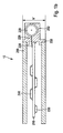
- FIG. 1a shows a plug-in housing 100 for a control unit 10.
- the housing 100 is box-shaped and has two open end faces 102 and 104.
- a circuit board 110 In the housing 100 is a circuit board 110.
- electrical and electronic components are arranged on the top and bottom of the circuit board 110. These are, for example, so-called SMD components ("surface-mounted device"), active or passive electronic components 130 and 140, which are contacted on the surface of the printed circuit board 110 by means of contact lugs 135.
- SMD components surface-mounted device
- active or passive electronic components 130 and 140 which are contacted on the surface of the printed circuit board 110 by means of contact lugs 135.
- two capacitors 122 and 124 which have a large height compared to the components 130 and 140.
- the capacitors 122 and 124 are soldered to the back side of the circuit board 110 via leads 126 passing through the circuit board 110.
- the open end face 104 of the housing 100 is closed by a closing element 150.
- the minimum height h of the housing is determined by the height of the capacitors 122 and 124.
- the second open end surface 102 is further closed by a connector element, not shown, which produces the electrical contact from the circuit board 110 to the outside.
- FIG. 1b a plug-in housing 200 is shown in which a circuit board 210 is arranged.
- the housing is closed by a closing element 250.
- a capacitor 220 is disposed in the termination member 250.
- the closing element 250 has a recess 252 which serves as a holder for the capacitor 250.
- the capacitor 220 is arranged in the terminating element so that its longitudinal axis is aligned parallel to the plane of the printed circuit board 210.
- the capacitor 220 is contacted via contact wires 226, which are passed through the closing element 250, with the guide plate 210, for example, soldered.
- the contact wires 226 extend flat and substantially parallel to the printed circuit board 210 and are contacted to the end element 250 facing edge region of the printed circuit board 210 with this at the solder joint 228.
- FIG. 1c shown insertion housing substantially corresponds to the FIG. 1b , Identical components are provided with the same reference numerals.
- a contact spring 229 is arranged on the edge region of the printed circuit board 210 facing the terminating element 250.
- the contact pin 227 of the capacitor 220 is in the contact spring 229 inserted.
- the electrical contact between the capacitor 220 and the printed circuit board 210 is established.
- FIG. 1d is a plug-in housing shown, which is also essentially from the FIG. 1b equivalent. Identical components are provided with the same reference numerals.
- a stamped grid 237 is arranged in the terminating element 250, on which the capacitor 220 is fastened and contacted, for example by welding or soldering.
- the punched grid 237 forms a direct plug connection to the printed circuit board.
- the printed circuit board has contact points 214, so-called land areas, on its edge region facing the closing element 250.
- the stamped grid 237 has spring contacts 238, which electrically contact the contact regions 214 on the printed circuit board 210 as soon as the terminating element 250 is plugged onto the printed circuit board 210.
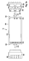
- FIG. 2a a plug-in housing 300 is also shown.
- the housing is box-shaped and has two open end faces 302 and 304.
- a printed circuit board 310 is arranged, which is equipped with electrical and / or electronic components, not shown.
- the printed circuit board 310 At its edge areas facing the open end faces 302 and 304 of the housing 300, the printed circuit board 310 has contact zones 314 and 312, so-called land areas.
- the housing 300 is closed by two end members 350 and 360, which are respectively inserted into the open end surfaces 302 and 304, as indicated by the arrows 370, and close the housing 300 to the outside. Electrical and / or electronic components, in this example two capacitors 322 and 324, are arranged in the terminating element 350.
- the longitudinal axes of the capacitors 322 and 324 are aligned parallel to the plane of the circuit board 310.
- the capacitors 322 and 324 are connected to the lead frame 355.
- the punched grid works with appropriate Contact areas 314 on the circuit board 310 together, thus establishing the electrical contact between the circuit board 310 and the components 322 and 324 ago.
- wire contacts can also be used.
- the cooling structures 354 are designed, for example, as cooling fins.
- a plug 380 is integrated, which makes the electrical contact from the circuit board 310 to the outside. This contacting is again via a direct plug connection.
- FIG. 2a indicated assembly sequence for a controller 10 with a plug-in housing 300, in which initially the circuit board 310 is disposed in the housing 300 and the housing 300 is then closed from both sides by termination elements 350 and 360, it is possible, first the circuit board 310 with the end element 350 and insert the assembly of printed circuit board 310 and terminating element 350 in the housing 300. Subsequently, the housing 300 is closed from the other side by the end member 360. Alternatively, first the printed circuit board can be connected to the terminating element 360, the arrangement of the printed circuit board 310 and the terminating element 360 can be inserted into the housing 300 and the housing 300 can subsequently be closed by the terminating element 350.
- FIG. 2b shown insertion housing substantially corresponds to the FIG. 2a , Identical components are provided with the same reference numerals.
- a plug element 382 is arranged which contacts the printed circuit board 310 to the outside.
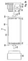
- a printed circuit board 410 equipped with electrical and / or electronic components, not shown, as well as separate components 422, 424 and 426 in a frame 405, which may be made of metal or plastic.
- the frame serves as a closure element 450 and is, as indicated by the arrow 470 inserted into a slide-in housing 400.
- the frame serves for holding and fixing the printed circuit board 410 in the housing 400.
- the components arranged separately from the printed circuit board 410 in the terminating element 450 in this example are two capacitors 422 and 424, as well as a coil 426, these being are arranged so that their respective longitudinal axis is parallel to the plane of the circuit board 410.
- circumferential sealing elements 407 are arranged, which seal the housing 400 to the outside against moisture and penetrating dirt.
Landscapes
- Engineering & Computer Science (AREA)
- Microelectronics & Electronic Packaging (AREA)
- Casings For Electric Apparatus (AREA)
- Piezo-Electric Or Mechanical Vibrators, Or Delay Or Filter Circuits (AREA)
- Cooling Or The Like Of Electrical Apparatus (AREA)
Applications Claiming Priority (2)
| Application Number | Priority Date | Filing Date | Title |
|---|---|---|---|
| DE102009054767A DE102009054767A1 (de) | 2009-12-16 | 2009-12-16 | Abschlusselement für ein Gehäuse |
| PCT/EP2010/069391 WO2011082945A1 (de) | 2009-12-16 | 2010-12-10 | Abschlusselement für ein gehäuse |
Publications (2)
| Publication Number | Publication Date |
|---|---|
| EP2514285A1 EP2514285A1 (de) | 2012-10-24 |
| EP2514285B1 true EP2514285B1 (de) | 2015-02-25 |
Family
ID=43639459
Family Applications (1)
| Application Number | Title | Priority Date | Filing Date |
|---|---|---|---|
| EP10798029.4A Not-in-force EP2514285B1 (de) | 2009-12-16 | 2010-12-10 | Abschlusselement für ein gehäuse |
Country Status (6)
| Country | Link |
|---|---|
| EP (1) | EP2514285B1 (enExample) |
| CN (1) | CN102668735B (enExample) |
| BR (1) | BR112012014756A2 (enExample) |
| DE (1) | DE102009054767A1 (enExample) |
| IN (1) | IN2012DN03116A (enExample) |
| WO (1) | WO2011082945A1 (enExample) |
Families Citing this family (3)
| Publication number | Priority date | Publication date | Assignee | Title |
|---|---|---|---|---|
| KR101460898B1 (ko) * | 2013-06-11 | 2014-11-14 | 현대오트론 주식회사 | 경사 구조물을 이용한 차량의 전자 제어 장치 및 그 제조 방법 |
| DE102015225159A1 (de) * | 2015-12-14 | 2017-06-14 | Continental Automotive Gmbh | Magnetfeldsensor mit einem Steckersockel |
| DE102020208489A1 (de) * | 2020-07-07 | 2022-01-13 | Robert Bosch Gesellschaft mit beschränkter Haftung | Gehäusevorrichtung und Verfahren zum Herstellen einer Gehäusevorrichtung |
Citations (1)
| Publication number | Priority date | Publication date | Assignee | Title |
|---|---|---|---|---|
| EP0689374A2 (de) * | 1994-06-24 | 1995-12-27 | WABCO GmbH | Elektronikmodul |
Family Cites Families (7)
| Publication number | Priority date | Publication date | Assignee | Title |
|---|---|---|---|---|
| US3258649A (en) | 1966-06-28 | Enclosure for electrical circuit devices | ||
| DE4012182A1 (de) * | 1990-04-14 | 1991-10-17 | Bosch Gmbh Robert | Elektrisches schalt- und steuergeraet, insbesondere fuer kraftfahrzeuge |
| DE4443501A1 (de) * | 1994-12-07 | 1996-06-13 | Bosch Gmbh Robert | Elektrisches Gerät |
| US6459042B1 (en) * | 1999-12-17 | 2002-10-01 | Autoliv Asp, Inc. | Electrical connector with an electrical component holder |
| DE10054589A1 (de) * | 2000-11-03 | 2002-05-08 | Siemens Ag | Elektronisches Gerät |
| DE10162600A1 (de) * | 2001-12-20 | 2003-07-10 | Bosch Gmbh Robert | Gehäuseanordnung für ein elektrisches Gerät |
| FR2865344A1 (fr) * | 2004-08-06 | 2005-07-22 | Siemens Vdo Automotive | Dispositif electronique, notamment pour compartiment moteur de vehicule |
-
2009
- 2009-12-16 DE DE102009054767A patent/DE102009054767A1/de not_active Withdrawn
-
2010
- 2010-12-10 BR BR112012014756A patent/BR112012014756A2/pt not_active Application Discontinuation
- 2010-12-10 CN CN201080057065.XA patent/CN102668735B/zh not_active Expired - Fee Related
- 2010-12-10 IN IN3116DEN2012 patent/IN2012DN03116A/en unknown
- 2010-12-10 EP EP10798029.4A patent/EP2514285B1/de not_active Not-in-force
- 2010-12-10 WO PCT/EP2010/069391 patent/WO2011082945A1/de not_active Ceased
Patent Citations (1)
| Publication number | Priority date | Publication date | Assignee | Title |
|---|---|---|---|---|
| EP0689374A2 (de) * | 1994-06-24 | 1995-12-27 | WABCO GmbH | Elektronikmodul |
Also Published As
| Publication number | Publication date |
|---|---|
| IN2012DN03116A (enExample) | 2015-09-18 |
| CN102668735B (zh) | 2015-09-16 |
| BR112012014756A2 (pt) | 2016-03-29 |
| DE102009054767A1 (de) | 2011-06-22 |
| CN102668735A (zh) | 2012-09-12 |
| EP2514285A1 (de) | 2012-10-24 |
| WO2011082945A1 (de) | 2011-07-14 |
Similar Documents
| Publication | Publication Date | Title |
|---|---|---|
| EP1145610B1 (de) | Elektronisches steuergerät | |
| DE19941690C2 (de) | Steuergerät und Lötverfahren | |
| DE19707709C1 (de) | Leiterplatte für elektrische Schaltungen und Verfahren zur Herstellung einer solchen Leiterplatte, sowie Anordnung einer Leiterplatte auf einem Stecksockel | |
| EP2191703B1 (de) | Gehäuse für eine elektrische schaltung, insbesondere eines steuergeräts eines fahrzeugs | |
| DE112014001338T5 (de) | Rechtwinklige Steckkopfanordnung | |
| DE20012623U1 (de) | Gehäuse für ein elektronisches Steuergerät in Fahrzeugen | |
| WO2011045228A2 (de) | Adapterplatte zur befestigung eines gehäuses in einem fahrzeug und korrespondierendes steuergerät | |
| DE112014001321T5 (de) | Elektronikkomponenten-Anordnungsaufbau und elektrischer Anschlusskasten | |
| DE102017125505A1 (de) | Steckerbuchse für Leiterplatinen | |
| EP3378289B1 (de) | Leiterplatte zum mechanischen fixieren eines gehäuses | |
| EP2036414B1 (de) | Befestigungseinrichtung und verfahren zur befestigung einer leiterplatte in einem gehäuse | |
| DE102005029686A1 (de) | Antenne und Mittel zum Befestigen der Antenne auf einem Fahrzeug sowie zum Anschließen der Antenne an ein oder mehrere Kabel eines im Fahrzeug verlegten Kabelbaumes | |
| DE10061613A1 (de) | Elektrische Steckvorrichtung mit einem Halter für ein elektronisches Bauteil | |
| DE202006000720U1 (de) | HF-Stecker-Befestigungsmittel | |
| EP2514285B1 (de) | Abschlusselement für ein gehäuse | |
| EP0818133A1 (de) | Steuergerät für ein kraftfahrzeug | |
| EP1282345A2 (de) | Gehäuse zur Aufnahme einer Leiterplatte mit elektronischen Bauteilen in Fahrzeugen | |
| WO2015052117A1 (de) | Elektronische schaltung | |
| DE3731413C2 (enExample) | ||
| DE102008016076B4 (de) | Verbinderschirmung, Verbindersystem und Verwendung | |
| DE102019102713A1 (de) | Antriebseinheit | |
| DE10129840B4 (de) | Elektrisches Gerät | |
| DE102011120056B4 (de) | Steckverbindung für eine Platine | |
| EP1659837B1 (de) | Kontaktierung eines Bauelementes auf einem Stanzgitter | |
| DE19854641C1 (de) | Steuergerät und Verfahren zum Einsetzen eines Steckverbinders in ein Steuergerät |
Legal Events
| Date | Code | Title | Description |
|---|---|---|---|
| PUAI | Public reference made under article 153(3) epc to a published international application that has entered the european phase |
Free format text: ORIGINAL CODE: 0009012 |
|
| 17P | Request for examination filed |
Effective date: 20120716 |
|
| AK | Designated contracting states |
Kind code of ref document: A1 Designated state(s): AL AT BE BG CH CY CZ DE DK EE ES FI FR GB GR HR HU IE IS IT LI LT LU LV MC MK MT NL NO PL PT RO RS SE SI SK SM TR |
|
| DAX | Request for extension of the european patent (deleted) | ||
| GRAP | Despatch of communication of intention to grant a patent |
Free format text: ORIGINAL CODE: EPIDOSNIGR1 |
|
| INTG | Intention to grant announced |
Effective date: 20141014 |
|
| GRAS | Grant fee paid |
Free format text: ORIGINAL CODE: EPIDOSNIGR3 |
|
| GRAA | (expected) grant |
Free format text: ORIGINAL CODE: 0009210 |
|
| AK | Designated contracting states |
Kind code of ref document: B1 Designated state(s): AL AT BE BG CH CY CZ DE DK EE ES FI FR GB GR HR HU IE IS IT LI LT LU LV MC MK MT NL NO PL PT RO RS SE SI SK SM TR |
|
| REG | Reference to a national code |
Ref country code: GB Ref legal event code: FG4D Free format text: NOT ENGLISH |
|
| REG | Reference to a national code |
Ref country code: CH Ref legal event code: EP |
|
| REG | Reference to a national code |
Ref country code: IE Ref legal event code: FG4D Free format text: LANGUAGE OF EP DOCUMENT: GERMAN |
|
| REG | Reference to a national code |
Ref country code: DE Ref legal event code: R096 Ref document number: 502010009005 Country of ref document: DE Effective date: 20150409 |
|
| REG | Reference to a national code |
Ref country code: AT Ref legal event code: REF Ref document number: 712940 Country of ref document: AT Kind code of ref document: T Effective date: 20150415 |
|
| REG | Reference to a national code |
Ref country code: NL Ref legal event code: VDEP Effective date: 20150225 |
|
| REG | Reference to a national code |
Ref country code: LT Ref legal event code: MG4D |
|
| PG25 | Lapsed in a contracting state [announced via postgrant information from national office to epo] |
Ref country code: LT Free format text: LAPSE BECAUSE OF FAILURE TO SUBMIT A TRANSLATION OF THE DESCRIPTION OR TO PAY THE FEE WITHIN THE PRESCRIBED TIME-LIMIT Effective date: 20150225 Ref country code: NO Free format text: LAPSE BECAUSE OF FAILURE TO SUBMIT A TRANSLATION OF THE DESCRIPTION OR TO PAY THE FEE WITHIN THE PRESCRIBED TIME-LIMIT Effective date: 20150525 Ref country code: HR Free format text: LAPSE BECAUSE OF FAILURE TO SUBMIT A TRANSLATION OF THE DESCRIPTION OR TO PAY THE FEE WITHIN THE PRESCRIBED TIME-LIMIT Effective date: 20150225 Ref country code: FI Free format text: LAPSE BECAUSE OF FAILURE TO SUBMIT A TRANSLATION OF THE DESCRIPTION OR TO PAY THE FEE WITHIN THE PRESCRIBED TIME-LIMIT Effective date: 20150225 Ref country code: SE Free format text: LAPSE BECAUSE OF FAILURE TO SUBMIT A TRANSLATION OF THE DESCRIPTION OR TO PAY THE FEE WITHIN THE PRESCRIBED TIME-LIMIT Effective date: 20150225 Ref country code: ES Free format text: LAPSE BECAUSE OF FAILURE TO SUBMIT A TRANSLATION OF THE DESCRIPTION OR TO PAY THE FEE WITHIN THE PRESCRIBED TIME-LIMIT Effective date: 20150225 |
|
| PG25 | Lapsed in a contracting state [announced via postgrant information from national office to epo] |
Ref country code: LV Free format text: LAPSE BECAUSE OF FAILURE TO SUBMIT A TRANSLATION OF THE DESCRIPTION OR TO PAY THE FEE WITHIN THE PRESCRIBED TIME-LIMIT Effective date: 20150225 Ref country code: RS Free format text: LAPSE BECAUSE OF FAILURE TO SUBMIT A TRANSLATION OF THE DESCRIPTION OR TO PAY THE FEE WITHIN THE PRESCRIBED TIME-LIMIT Effective date: 20150225 Ref country code: IS Free format text: LAPSE BECAUSE OF FAILURE TO SUBMIT A TRANSLATION OF THE DESCRIPTION OR TO PAY THE FEE WITHIN THE PRESCRIBED TIME-LIMIT Effective date: 20150625 Ref country code: GR Free format text: LAPSE BECAUSE OF FAILURE TO SUBMIT A TRANSLATION OF THE DESCRIPTION OR TO PAY THE FEE WITHIN THE PRESCRIBED TIME-LIMIT Effective date: 20150526 |
|
| PG25 | Lapsed in a contracting state [announced via postgrant information from national office to epo] |
Ref country code: NL Free format text: LAPSE BECAUSE OF FAILURE TO SUBMIT A TRANSLATION OF THE DESCRIPTION OR TO PAY THE FEE WITHIN THE PRESCRIBED TIME-LIMIT Effective date: 20150225 |
|
| PG25 | Lapsed in a contracting state [announced via postgrant information from national office to epo] |
Ref country code: EE Free format text: LAPSE BECAUSE OF FAILURE TO SUBMIT A TRANSLATION OF THE DESCRIPTION OR TO PAY THE FEE WITHIN THE PRESCRIBED TIME-LIMIT Effective date: 20150225 Ref country code: DK Free format text: LAPSE BECAUSE OF FAILURE TO SUBMIT A TRANSLATION OF THE DESCRIPTION OR TO PAY THE FEE WITHIN THE PRESCRIBED TIME-LIMIT Effective date: 20150225 Ref country code: RO Free format text: LAPSE BECAUSE OF FAILURE TO SUBMIT A TRANSLATION OF THE DESCRIPTION OR TO PAY THE FEE WITHIN THE PRESCRIBED TIME-LIMIT Effective date: 20150225 Ref country code: CZ Free format text: LAPSE BECAUSE OF FAILURE TO SUBMIT A TRANSLATION OF THE DESCRIPTION OR TO PAY THE FEE WITHIN THE PRESCRIBED TIME-LIMIT Effective date: 20150225 Ref country code: SK Free format text: LAPSE BECAUSE OF FAILURE TO SUBMIT A TRANSLATION OF THE DESCRIPTION OR TO PAY THE FEE WITHIN THE PRESCRIBED TIME-LIMIT Effective date: 20150225 |
|
| REG | Reference to a national code |
Ref country code: DE Ref legal event code: R097 Ref document number: 502010009005 Country of ref document: DE |
|
| PG25 | Lapsed in a contracting state [announced via postgrant information from national office to epo] |
Ref country code: PL Free format text: LAPSE BECAUSE OF FAILURE TO SUBMIT A TRANSLATION OF THE DESCRIPTION OR TO PAY THE FEE WITHIN THE PRESCRIBED TIME-LIMIT Effective date: 20150225 |
|
| REG | Reference to a national code |
Ref country code: FR Ref legal event code: PLFP Year of fee payment: 6 |
|
| PLBE | No opposition filed within time limit |
Free format text: ORIGINAL CODE: 0009261 |
|
| STAA | Information on the status of an ep patent application or granted ep patent |
Free format text: STATUS: NO OPPOSITION FILED WITHIN TIME LIMIT |
|
| 26N | No opposition filed |
Effective date: 20151126 |
|
| PG25 | Lapsed in a contracting state [announced via postgrant information from national office to epo] |
Ref country code: SI Free format text: LAPSE BECAUSE OF FAILURE TO SUBMIT A TRANSLATION OF THE DESCRIPTION OR TO PAY THE FEE WITHIN THE PRESCRIBED TIME-LIMIT Effective date: 20150225 |
|
| PG25 | Lapsed in a contracting state [announced via postgrant information from national office to epo] |
Ref country code: BE Free format text: LAPSE BECAUSE OF NON-PAYMENT OF DUE FEES Effective date: 20151231 |
|
| PG25 | Lapsed in a contracting state [announced via postgrant information from national office to epo] |
Ref country code: LU Free format text: LAPSE BECAUSE OF FAILURE TO SUBMIT A TRANSLATION OF THE DESCRIPTION OR TO PAY THE FEE WITHIN THE PRESCRIBED TIME-LIMIT Effective date: 20151210 Ref country code: MC Free format text: LAPSE BECAUSE OF FAILURE TO SUBMIT A TRANSLATION OF THE DESCRIPTION OR TO PAY THE FEE WITHIN THE PRESCRIBED TIME-LIMIT Effective date: 20150225 |
|
| REG | Reference to a national code |
Ref country code: CH Ref legal event code: PL |
|
| REG | Reference to a national code |
Ref country code: IE Ref legal event code: MM4A |
|
| PG25 | Lapsed in a contracting state [announced via postgrant information from national office to epo] |
Ref country code: LI Free format text: LAPSE BECAUSE OF NON-PAYMENT OF DUE FEES Effective date: 20151231 Ref country code: IE Free format text: LAPSE BECAUSE OF NON-PAYMENT OF DUE FEES Effective date: 20151210 Ref country code: CH Free format text: LAPSE BECAUSE OF NON-PAYMENT OF DUE FEES Effective date: 20151231 |
|
| REG | Reference to a national code |
Ref country code: FR Ref legal event code: PLFP Year of fee payment: 7 |
|
| REG | Reference to a national code |
Ref country code: AT Ref legal event code: MM01 Ref document number: 712940 Country of ref document: AT Kind code of ref document: T Effective date: 20151210 |
|
| PG25 | Lapsed in a contracting state [announced via postgrant information from national office to epo] |
Ref country code: SM Free format text: LAPSE BECAUSE OF FAILURE TO SUBMIT A TRANSLATION OF THE DESCRIPTION OR TO PAY THE FEE WITHIN THE PRESCRIBED TIME-LIMIT Effective date: 20150225 Ref country code: AT Free format text: LAPSE BECAUSE OF NON-PAYMENT OF DUE FEES Effective date: 20151210 Ref country code: HU Free format text: LAPSE BECAUSE OF FAILURE TO SUBMIT A TRANSLATION OF THE DESCRIPTION OR TO PAY THE FEE WITHIN THE PRESCRIBED TIME-LIMIT; INVALID AB INITIO Effective date: 20101210 Ref country code: BG Free format text: LAPSE BECAUSE OF FAILURE TO SUBMIT A TRANSLATION OF THE DESCRIPTION OR TO PAY THE FEE WITHIN THE PRESCRIBED TIME-LIMIT Effective date: 20150225 |
|
| PG25 | Lapsed in a contracting state [announced via postgrant information from national office to epo] |
Ref country code: CY Free format text: LAPSE BECAUSE OF FAILURE TO SUBMIT A TRANSLATION OF THE DESCRIPTION OR TO PAY THE FEE WITHIN THE PRESCRIBED TIME-LIMIT Effective date: 20150225 |
|
| PG25 | Lapsed in a contracting state [announced via postgrant information from national office to epo] |
Ref country code: MT Free format text: LAPSE BECAUSE OF FAILURE TO SUBMIT A TRANSLATION OF THE DESCRIPTION OR TO PAY THE FEE WITHIN THE PRESCRIBED TIME-LIMIT Effective date: 20150225 |
|
| REG | Reference to a national code |
Ref country code: FR Ref legal event code: PLFP Year of fee payment: 8 |
|
| PG25 | Lapsed in a contracting state [announced via postgrant information from national office to epo] |
Ref country code: TR Free format text: LAPSE BECAUSE OF FAILURE TO SUBMIT A TRANSLATION OF THE DESCRIPTION OR TO PAY THE FEE WITHIN THE PRESCRIBED TIME-LIMIT Effective date: 20150225 Ref country code: MK Free format text: LAPSE BECAUSE OF FAILURE TO SUBMIT A TRANSLATION OF THE DESCRIPTION OR TO PAY THE FEE WITHIN THE PRESCRIBED TIME-LIMIT Effective date: 20150225 Ref country code: PT Free format text: LAPSE BECAUSE OF FAILURE TO SUBMIT A TRANSLATION OF THE DESCRIPTION OR TO PAY THE FEE WITHIN THE PRESCRIBED TIME-LIMIT Effective date: 20150225 |
|
| PG25 | Lapsed in a contracting state [announced via postgrant information from national office to epo] |
Ref country code: AL Free format text: LAPSE BECAUSE OF FAILURE TO SUBMIT A TRANSLATION OF THE DESCRIPTION OR TO PAY THE FEE WITHIN THE PRESCRIBED TIME-LIMIT Effective date: 20150225 |
|
| PGFP | Annual fee paid to national office [announced via postgrant information from national office to epo] |
Ref country code: ES Payment date: 20181218 Year of fee payment: 17 Ref country code: IT Payment date: 20181218 Year of fee payment: 9 |
|
| GBPC | Gb: european patent ceased through non-payment of renewal fee |
Effective date: 20191210 |
|
| PG25 | Lapsed in a contracting state [announced via postgrant information from national office to epo] |
Ref country code: GB Free format text: LAPSE BECAUSE OF NON-PAYMENT OF DUE FEES Effective date: 20191210 Ref country code: IT Free format text: LAPSE BECAUSE OF NON-PAYMENT OF DUE FEES Effective date: 20191210 |
|
| PGFP | Annual fee paid to national office [announced via postgrant information from national office to epo] |
Ref country code: FR Payment date: 20211220 Year of fee payment: 12 |
|
| PGFP | Annual fee paid to national office [announced via postgrant information from national office to epo] |
Ref country code: DE Payment date: 20220224 Year of fee payment: 12 |
|
| REG | Reference to a national code |
Ref country code: DE Ref legal event code: R119 Ref document number: 502010009005 Country of ref document: DE |
|
| PG25 | Lapsed in a contracting state [announced via postgrant information from national office to epo] |
Ref country code: DE Free format text: LAPSE BECAUSE OF NON-PAYMENT OF DUE FEES Effective date: 20230701 |
|
| PG25 | Lapsed in a contracting state [announced via postgrant information from national office to epo] |
Ref country code: FR Free format text: LAPSE BECAUSE OF NON-PAYMENT OF DUE FEES Effective date: 20221231 |