EP2514280B1 - An apparatus for treating a surface with at least one gliding arc source - Google Patents
An apparatus for treating a surface with at least one gliding arc source Download PDFInfo
- Publication number
- EP2514280B1 EP2514280B1 EP10790447.6A EP10790447A EP2514280B1 EP 2514280 B1 EP2514280 B1 EP 2514280B1 EP 10790447 A EP10790447 A EP 10790447A EP 2514280 B1 EP2514280 B1 EP 2514280B1
- Authority
- EP
- European Patent Office
- Prior art keywords
- electrodes
- unit
- plasma
- electrode
- control unit
- Prior art date
- Legal status (The legal status is an assumption and is not a legal conclusion. Google has not performed a legal analysis and makes no representation as to the accuracy of the status listed.)
- Not-in-force
Links
- 238000001816 cooling Methods 0.000 claims description 47
- 239000002826 coolant Substances 0.000 claims description 21
- 238000004891 communication Methods 0.000 claims description 19
- 239000012809 cooling fluid Substances 0.000 claims description 3
- 210000002381 plasma Anatomy 0.000 description 97
- 239000007789 gas Substances 0.000 description 72
- 230000005684 electric field Effects 0.000 description 8
- 239000012530 fluid Substances 0.000 description 8
- 238000010891 electric arc Methods 0.000 description 6
- 230000003287 optical effect Effects 0.000 description 6
- 239000000203 mixture Substances 0.000 description 5
- 229920000728 polyester Polymers 0.000 description 5
- RYGMFSIKBFXOCR-UHFFFAOYSA-N Copper Chemical compound [Cu] RYGMFSIKBFXOCR-UHFFFAOYSA-N 0.000 description 4
- XAGFODPZIPBFFR-UHFFFAOYSA-N aluminium Chemical compound [Al] XAGFODPZIPBFFR-UHFFFAOYSA-N 0.000 description 4
- 229910052782 aluminium Inorganic materials 0.000 description 4
- 239000010949 copper Substances 0.000 description 4
- 229910052802 copper Inorganic materials 0.000 description 4
- 238000000034 method Methods 0.000 description 4
- 238000004381 surface treatment Methods 0.000 description 4
- WFKWXMTUELFFGS-UHFFFAOYSA-N tungsten Chemical compound [W] WFKWXMTUELFFGS-UHFFFAOYSA-N 0.000 description 4
- 239000010937 tungsten Substances 0.000 description 4
- 229910052721 tungsten Inorganic materials 0.000 description 4
- 239000004411 aluminium Substances 0.000 description 3
- 230000007423 decrease Effects 0.000 description 3
- 230000003247 decreasing effect Effects 0.000 description 3
- 238000013461 design Methods 0.000 description 3
- 238000001686 rotational spectrum Methods 0.000 description 3
- 229910001220 stainless steel Inorganic materials 0.000 description 3
- 239000010935 stainless steel Substances 0.000 description 3
- ATUOYWHBWRKTHZ-UHFFFAOYSA-N Propane Chemical compound CCC ATUOYWHBWRKTHZ-UHFFFAOYSA-N 0.000 description 2
- QVGXLLKOCUKJST-UHFFFAOYSA-N atomic oxygen Chemical compound [O] QVGXLLKOCUKJST-UHFFFAOYSA-N 0.000 description 2
- 230000005672 electromagnetic field Effects 0.000 description 2
- 238000005516 engineering process Methods 0.000 description 2
- 239000000463 material Substances 0.000 description 2
- VNWKTOKETHGBQD-UHFFFAOYSA-N methane Chemical compound C VNWKTOKETHGBQD-UHFFFAOYSA-N 0.000 description 2
- 239000001301 oxygen Substances 0.000 description 2
- 229910052760 oxygen Inorganic materials 0.000 description 2
- 238000005086 pumping Methods 0.000 description 2
- 230000005855 radiation Effects 0.000 description 2
- 239000007787 solid Substances 0.000 description 2
- 230000003685 thermal hair damage Effects 0.000 description 2
- XLYOFNOQVPJJNP-UHFFFAOYSA-N water Substances O XLYOFNOQVPJJNP-UHFFFAOYSA-N 0.000 description 2
- OKTJSMMVPCPJKN-UHFFFAOYSA-N Carbon Chemical compound [C] OKTJSMMVPCPJKN-UHFFFAOYSA-N 0.000 description 1
- OTMSDBZUPAUEDD-UHFFFAOYSA-N Ethane Chemical compound CC OTMSDBZUPAUEDD-UHFFFAOYSA-N 0.000 description 1
- 238000004833 X-ray photoelectron spectroscopy Methods 0.000 description 1
- 239000000853 adhesive Substances 0.000 description 1
- 230000001070 adhesive effect Effects 0.000 description 1
- 150000001298 alcohols Chemical class 0.000 description 1
- 239000001273 butane Substances 0.000 description 1
- 229910052799 carbon Inorganic materials 0.000 description 1
- 238000000576 coating method Methods 0.000 description 1
- 238000002485 combustion reaction Methods 0.000 description 1
- 239000002131 composite material Substances 0.000 description 1
- 230000007797 corrosion Effects 0.000 description 1
- 238000005260 corrosion Methods 0.000 description 1
- 230000001419 dependent effect Effects 0.000 description 1
- 239000010432 diamond Substances 0.000 description 1
- 230000000694 effects Effects 0.000 description 1
- 239000007772 electrode material Substances 0.000 description 1
- 239000000835 fiber Substances 0.000 description 1
- 125000000524 functional group Chemical group 0.000 description 1
- 238000010438 heat treatment Methods 0.000 description 1
- 229930195733 hydrocarbon Natural products 0.000 description 1
- 150000002430 hydrocarbons Chemical class 0.000 description 1
- 150000002500 ions Chemical class 0.000 description 1
- 238000012986 modification Methods 0.000 description 1
- 230000004048 modification Effects 0.000 description 1
- IJDNQMDRQITEOD-UHFFFAOYSA-N n-butane Chemical compound CCCC IJDNQMDRQITEOD-UHFFFAOYSA-N 0.000 description 1
- OFBQJSOFQDEBGM-UHFFFAOYSA-N n-pentane Natural products CCCCC OFBQJSOFQDEBGM-UHFFFAOYSA-N 0.000 description 1
- 230000001590 oxidative effect Effects 0.000 description 1
- 238000009832 plasma treatment Methods 0.000 description 1
- 238000012545 processing Methods 0.000 description 1
- 239000001294 propane Substances 0.000 description 1
- 238000003466 welding Methods 0.000 description 1
Images


Classifications
-
- H—ELECTRICITY
- H05—ELECTRIC TECHNIQUES NOT OTHERWISE PROVIDED FOR
- H05H—PLASMA TECHNIQUE; PRODUCTION OF ACCELERATED ELECTRICALLY-CHARGED PARTICLES OR OF NEUTRONS; PRODUCTION OR ACCELERATION OF NEUTRAL MOLECULAR OR ATOMIC BEAMS
- H05H1/00—Generating plasma; Handling plasma
- H05H1/24—Generating plasma
- H05H1/48—Generating plasma using an arc
- H05H1/482—Arrangements to provide gliding arc discharges
Definitions
- the invention relates to an apparatus for treating a surface with at least one gliding arc source.
- the invention further relates to a corresponding method and system.
- Non-equilibrium plasmas are preferably used for surface treatment in industry.
- a gliding arc may be utilized whereby the power of the plasma may be increased by keeping the non-equilibrium condition, see e,g. A. Fridman et al., "Gliding arc discharge", Progress in Energy and Combustion Science 25, (1999), pages 211 - 231 , or Kusano et al.: “Gliding are discharge: application for adhesion improvement of fibre reinforced polyester composites", Surface and Coatings Technology, vol, 202, 22-23 (2008), pages 5579-5582.
- an apparatus for treating a surface with at least one gliding arc source comprising
- an efficient cooling of the electrodes is provided while ensuring an efficient plasma generation.
- At least one of the electrodes may comprise a tubular portion fluidly coupled to the cooling unit 201, wherein the electrode further comprises an outer surface comprising at least one portion facing the other one of the electrodes; wherein an intersection of said at least one portion of the outer surface of the electrode with a plane normal to a longitudinal direction of the electrode has a curvature with a radius of curvature less than 3mm.
- the tubular portion may define said longitudinal direction. Said portion of the outer surface may thus be curved in a plane normal to said longitudinal direction and have a radius of curvature smaller than 3mm, preferably smaller than 2mm.
- the electrode may be formed as a tube having a radius no larger than 3mm.
- the electrode may comprise a tubular portion, e.g. a tubular portion with a radius no less than 3mm, and a protrusion extending radially from the tubular portion where the protrusion has a radially outward edge portion.
- the edge portion may be curved in a plane normal to said longitudinal direction and have a radius of curvature smaller than 3mm, preferably smaller than 2mm.
- an apparatus for treating a surface with at least one gliding arc source comprising
- an efficient control of the electrodes is provided while ensuring an efficient plasma generation.
- an apparatus for treating a surface with at least one gliding arc source comprising at least one gas flow controlling unit for each gliding arc source; and a set of electrodes; wherein the at least one gas flow controlling unit and the set of electrodes are controlled to provide a plasma comprising a rotational temperature at the point of arc ignition above approximately 2000K and more preferably above 3000K.
- Embodiments of the present invention also relates to a method corresponding to embodiments of the device.
- the invention relates to a method of treating a surface with at least one gliding arc source comprising controlling at least one gas flow controlling unit and controlling a set of electrodes; and providing a plasma via the at least one gas flow controlling unit and the set of electrodes; and controlling the plasma to comprise a rotational temperature at the point of arc ignition above approximately 2000K and more preferably 3000K.
- the method and embodiments thereof correspond to the device and embodiments thereof and have the same advantages for the same reasons.
- Embodiments of the present invention also relate to a system corresponding to embodiments of the device.
- the invention relates to a system for treating a surface with at least one gliding arc source comprising an apparatus according to an embodiment of the invention and a sample, wherein the apparatus is adapted to provide a plasma to treat the sample surface.
- At least one of the electrodes comprises a tube having a first end and a second end wherein the tube is configured to receive, during operation a coolant at said first end and discharge the coolant at said second end, wherein the centre of the cross-section of the tube at the first end is displaced relative to the centre of the cross-section of the tube at the second end.
- the cross section of the tube may have any shape such as round or rectangular.
- the cross section of the tube may have a width between 1 mm and 50 cm, between 0.5 cm and 20 cm, between 1 cm and 10 cm or between 2 cm and 8 cm.
- the cross section of the tube includes a portion facing the other electrode and the plasma. At least a part of this portion may be curved with a radius of curvature less than 3mm, e.g. les than 2mm. Both electrodes may comprise a tube.
- the tube may have approximately a U shape where the first end and the second end are positioned at the upper part of the U approximately at the same height.
- an electrode capable of being efficiently cooled by circulating coolant.
- the flow resistance is lowered allowing an even better cooling by designing the electrode as a tube with a larger inner diameter.
- At least one of the electrodes comprises a tubular portion wherein the tubular portion, at least along a portion of its outer surface, comprises a protrusion configured to lower the needed voltage applied to the electrodes to ignite the plasma, relatively to the needed voltage when the at least one electrode does not comprise said protrusion.
- the protrusion may be an elongated, flat, e.g. blade-shaped, element elongated along the longitudinal direction of the electrode and having a width at an end distal to the electrode, which width is smaller than its longitudinal dimension and smaller than the height of the protrusion.
- the protrusion may extend along at least a portion of the outer surface of the tubular portion.
- the protrusion may project from the outer surface of the tubular portion towards the other electrode and the plasma, thus defining at least one edge portion facing the other electrode.
- the edge portion may be round and have a radius of curvature less than 3mm, e.g. less than 2mm. The radius of curvature may be measured in an intersection of the protrusion with a cross-sectional plane of the electrode normal to the longitudinal direction of the electrode.
- the electrode protrusion e.g. electrode attachment, may protrude in a direction approximately towards the other electrode.
- the electrode protrusion may protrude with a height of at least 1 mm, 2 mm, 5 mm, 1 cm, 2 cm, 5 cm, or 10 cm.
- the electrode attachment may protrude with a height no more than 20 cm, 10 cm, 5 cm, 2 cm, 1 cm, or 5 mm.
- the electrode protrusion may have a shape such that the intensity of the electric field around the part of the electrode comprising the protrusion is increased relatively to the intensity of electrical field of the same part of the electrode if the protrusion where removed, when a voltage is applied, whereby the voltage needed to ignite the plasma is lowered.
- the electrode protrusion may be attached to the tubular portion after the tubular portion is formed or the tubular portion and the attachment may be formed as an integral body. It will further be appreciated that more than one protrusion, e.g. more than one attachment, may be provided at each electrode.
- a cross section of the tubular portion being perpendicular to the longitudinal direction of the tubular portion, comprising a part of the electrode protrusion may have a shape such that a first surface area defined between a first line and a second line originating in the centre of said cross section is at least a factor A larger than a second surface area defined between said second line and a third line originating in said centre, wherein the angle between said first and said second line, and said second line and said third line is B, wherein the first and the second line is positioned so that the first surface area comprises the electrode protrusion, and the third line is positioned so that the first surface area and the second surface area do not overlap.
- A may be chosen from approximately 1.1, 1.5, 2, 3, 4, 5, or 10
- B may be chosen from approximately 180 degrees, 135 degrees, 90 degrees, 45 degrees, 30 degrees, 20, degrees, 10 degrees, or 5 degrees.
- the apparatus further comprises a computational unit communicatively coupled to the control unit via a first communication link and to a sensor via a second communication link, wherein said sensor is adapted to measure a parameter indicative of the resistance of at least one of the electrodes, and where the computational unit is adapted to calculate a feedback signal based on the measured parameter wherein the computational unit is further adapted to transmit the feedback signal to the control unit wherein the control unit is adapted to control the cooling unit responsive to the received feed back signal such that the cooling unit is controllable via a feedback loop.
- the computational unit may be adapted to calculate a feedback signal based on the measured parameter wherein the computational unit is further adapted to feed the feedback signal to the control unit wherein the control unit is adapted to control the power supply responsive to the received feedback signal such that the power supply is controllable via a feedback loop.
- the parameter may be the temperature of the electrode, or the resistance of the electrode.
- the temperature of the electrode may be measured by attaching a temperature sensor to the electrode and/or measuring the Infra red and/or visible radiation from the electrode.
- the temperature of the electrodes may also be estimated by the temperatures of the fluid (coolant) before and after cooling the electrodes, or by measuring the temperature of the sample 112.
- the feedback signal may be generated securing that the resistance of the electrode is maintained below a predetermined value e.g. two or three times larger resistance than the resistance at room temperature, if the temperature of the electrode increases the feedback signal may secure that cooling unit cools the electrode more e.g. by increasing the flow rate of the coolant and/or decreasing the temperature of the coolant.
- the feedback signal may cause the cooling unit to cool the electrode less e.g. by decreasing the flow rate of the coolant and/or increasing the temperature of the coolant.
- the feedback signal may be generated securing that the temperature of the bulk part of the electrode is not raised with more than 3/ ⁇ from room temperature (e.g. from 20 degrees Celsius), where ⁇ is the temperature coefficient of the linear relationship between the resistance and temperature. For copper and aluminium 3/ ⁇ is approximately 769 degrees Celsius, and for tungsten it is 667 degrees Celsius.
- the feedback signal may be generated securing that the temperature of the electrode is not raised with more than 2/ ⁇ from room temperature, where ⁇ is the temperature coefficient of the linear relationship between the resistance and temperature.
- ⁇ is the temperature coefficient of the linear relationship between the resistance and temperature.
- the feedback signal may be generated securing that the temperature of the electrode is not raised with more than 1/ ⁇ from room temperature, where ⁇ is the temperature coefficient of the linear relationship between the resistance and temperature.
- ⁇ is the temperature coefficient of the linear relationship between the resistance and temperature.
- For copper and aluminium 1/ ⁇ is approximately 256 degrees Celsius, for tungsten it is 222 degrees Celsius, and for stainless steel it is 1000 degrees Celsius.
- Figure 1 shows an embodiment of a device 100 for generating at least one gliding arc plasma 107 such as one gliding arc plasma or a plurality of gliding arc plasmas.
- the device 100 may comprise a gas flow controlling unit 104, a set of electrodes 102 and a power supply 101.
- the gas flow controlling unit 104 may be exemplified as a needle valve, which is able to regulate the flow, or a float type flow meter, which is able to regulate the flow and measure the flow, or a mass flow controller, which is able to regulate the flow via an external electric signal and to measure the flow.
- the gas flow controlling unit 104 may comprise a plurality of flow meters such as a flow meter for each gas component in a multiple component gas mixture.
- the gas flow controlling unit 104 may comprise two flow meters when providing a two component gas mixture to the plasma 107, one flow meter for each component in a two component gas mixture.
- the gas flow controlling unit and the power supply may be electrically coupled to the electric grid e.g. via respective electric wires. Thereby the electric grid may provide power to the gas flow controlling unit and to the power supply 101.
- the power supply 101 may be electrically connected to the set of electrodes 102 e.g. via electrical wires 113.
- the voltage required may depend on e.g. the gap between the electrodes. If the gap is smaller, the ignition voltage is also smaller.
- the power supply may be configured to supply a voltage between 300 V and 40 kV. The operation of the arc requires normally requires much lower voltages than the ignition of the plasma.
- the power supply 101 may provide (electric) energy to the set of electrodes 102.
- the power supply 101 may be connected to the electrical grid from where the power supply 101 may receive electric energy.
- the power supply 101 may transform the power, e.g. alternating current, received from the electric grid into a format suitable for the set of electrodes, e.g. direct current or alternating current.
- the set of electrodes 102 may generate a gliding arc using either direct current (DC) or alternating current (AC).
- the driving frequency of the alternating current may be between 5 Hz and 2 MHz, preferably between 50 Hz and 500 kHz.
- the power supply 101 may additionally control the surface temperature of a sample 112 to be treated by the at least one gliding arc plasma 107. By increasing the power from the power supply 101 to the set of electrodes 102, the surface temperature of the sample may be increased.
- the gas flow controlling unit 104 may inject gas into a plasma 107 contained in a volume.
- a plasma may be created in the volume.
- a plasma 107 may be characterized as a partially ionized gas, in which a certain proportion of electrons are free rather than being bound to an atom or a molecule in the gas.
- suitable gases to be fed to the discharge include air, N 2 , O 2 , Ar, He, Ne, CO 2 , H 2 O, hydro-carbons (such as methane, ethane, propane, butane, alcohols, etc.), etc. or mixtures of the above.
- the gas flow controlling unit 104 may inject a gas into the plasma as indicated by the arrow 194.
- the volume containing the plasma may be partly or wholly expanded by the set of electrodes 102 and the gas flow 194.
- the gas flow controlling unit 104 may be controlled manually by a person setting the flow rate of the gas injected into the plasma 107.
- the set of electrodes 102 may, for example, comprise two electrodes having a radius of axial curvature.
- the radius of axial curvature 901 may be at least approximately 20 mm (more preferably > 40 mm).
- the set of electrodes may comprise two straight electrodes.
- the two electrodes may be positioned with a distance between approximately 0.2 mm and 20 mm (preferably 0.2 mm and 10 mm) between them at the point of minimal distance.
- the point of minimum distance between the electrodes corresponds to the point of ignition.
- this may be the point of ignition.
- the ignition generally occurs only if the electric field is strong enough, i.e. the point of ignition is generally a location along the electrode where the electrical field between the electrodes is sufficiently strong.
- the set of electrodes 102 may comprise more than two electrodes e.g. three or four electrodes.
- the arc discharge is extended by a high speed gas flow from the gas flow controlling unit 104.
- the input power, provided by the power supply 101, of the arc can be high e.g. in the order of 0,2 - 5 kW per one gliding arc.
- the input power to the at least one gliding arc plasma may be controlled such that electrons in the at least one gliding arc have high temperature, e.g. above 0.5 eV.
- Figure 2 shows an embodiment of a device 200 for generating at least one gliding arc plasma 107 such as one gliding arc plasma or a plurality of gliding arc plasmas.
- the device 200 may comprise the technical features of figure 1 .
- each electrode in the set of electrodes may be hollow enabling passage of a fluid through the set of electrodes.
- the device 200 may comprise a cooling unit 201.
- the cooling unit may be fluidly coupled to the set of electrodes 102 e.g. via a tube 202 or the like. Thereby, the cooling unit 201 may cool the set of electrodes 102 e.g. by pumping a coolant through the set of electrodes 102 via the tube 202.
- the cooling unit 201 may be electrically coupled to the power supply 101 via an electric wire 204 or to an electric grid (not shown).
- the device 200 may further comprise an actuator 110 adapted to translate a sample 112 through the plasma 107.
- the actuator 110 may comprise an X-Y-table.
- the actuator 110 may be controlled manually by an operator.
- the X-Y-table of the actuator 110 may be hollow enabling a fluid to pass through the actuator 110.
- the cooling unit 201 may be fluidly coupled to the actuator 110 e.g. via a tube 203 or the like. Thereby, the cooling unit 201 is able to cool the actuator 110 by pumping a coolant such as water through the actuator 110.
- the device 200 is able to generate a plasma 107 and to surface treat a sample 112.
- Figure 3 shows an embodiment of a device 300 for generating at least one gliding arc plasma 107 such as one gliding arc plasma or a plurality of gliding arc plasmas.
- the device 300 may comprise a power supply 101, a control unit 103, at least one gas flow controlling unit 104 (e.g. one gas flow controlling unit) and a set of electrodes 102.
- the power supply 101 may be electrically communicated with the control unit 103 e.g. via an electrical wire 105, such that the control unit 103 may control the power supply 101.
- the control unit 103 may control the power provided to the at least one gas flow controlling unit 104 e.g. via electric wire 113.
- the set of electrodes 102 may be electrically coupled to the power supply 101 via e.g. an electric wire 106, and communicatively coupled to the control unit 103 via a wireless and/or wired communication link 106.
- the communication link may be established via e.g. an electrical wire and/or Bluetooth.
- the control unit 103 may control the frequency and/or the amplitude of the power supplied to the set of electrodes 102, and via the electric wire 106, the power supply may provide power to the set of electrodes 102.
- control unit 103 may control the at least one gas flow controlling unit 104.
- the at least one gas flow controlling unit 104 may be communicatively coupled to the control unit 103 e.g. by a wireless and/or wired communication link 113.
- the communication link may be established via an electrical wire and/or Bluetooth.
- the control unit 103 may control the amount of gas and/or the flow rate of gas injected by the at least one gas flow controlling unit 104.
- the control unit 103 may comprise controlling flow of the gas used in the plasma 107 and thus, for example, the gas in the plasma may be cooled while the electron temperature is substantially maintained e.g. within +/- 30 %.
- the at least one gas flow controlling unit 104 may inject gas into a plasma 107 contained in a volume via the set of electrodes 102.
- a plasma may be created in the volume.
- a plasma 107 may be characterized as a partially ionized gas, in which a certain proportion of electrons are free rather than being bound to an atom or a molecule in the gas. The ability of positive and negative charges to move somewhat independently makes the plasma electrically conductive so that it responds strongly to electromagnetic fields.
- the set of electrodes 102 may, for example, comprise two or more electrodes having a radius of axial curvature.
- the radius of axial curvature (see 901 in figure 10 for a definition of axial curvature) may be approximately more than 20mm (preferably > 40 mm).
- the set of electrodes may comprise two straight electrodes. Further, the two electrodes may be positioned with a distance between approximately 0,2 mm and 20 mm (preferably 0.2 mm and 10 mm) between them at the point of minimal distance.
- the input power of the arc can be high e.g. in the order of 0,2 - 5 kW per one gliding arc.
- the input power to the at least one gliding arc plasma may be controlled such that electrons in the at least one gliding arc have high temperature, e.g. above 0,5 eV.
- the control unit 103 may be adapted to control the input power to the at least one gliding arc plasma via the set of electrodes 102 such that electrons in the at least one gliding arc have high temperature, e.g. above 0,5 eV, and such that the energy density in the at least one gliding arc is high (typically at least 200 W, preferably at least 400 W).
- the device 300 may further comprise a cooling unit 201 which may be controlled by the control unit 103.
- the cooling unit 201 may be communicatively coupled to the control unit 103 e.g. by a wireless and/or wired communication link 109 such as an electrical wire and/or Bluetooth.
- the cooling unit 201 may be fluidly connected to the set of electrodes 102 via e.g. a tube 202 or the like.
- the electrodes 102 may be hollow to enable a fluid to pass through them.
- the cooling unit 201 may be adapted to provide a coolant to the set of electrodes 102.
- the coolant may, for example, be water, oil or air.
- the coolant may be an insulating fluid and/or a fluid with high resistance.
- a gas may be fed through the tubes of the electrodes for cooling, and all or a part of the gas may subsequently be fed to the plasma.
- the cooling unit 201 may optionally be fluidly connected to the X-Y table 110 via a tube 203.
- the device 300 may further comprise an actuator 110 adapted to translate a sample 112 through the plasma 107.
- the actuator 110 may comprise an X-Y-table.
- the actuator 110 may be communicatively coupled to the control unit 103 e.g. by a wireless and/or wired communication link 111 such as an electrical wire and/or Bluetooth.
- the control unit 103 is adapted to control the actuator 110 such as for example the speed by which the sample 112 is translated through the plasma 107.
- Figure 4 shows an embodiment of a set of electrodes 102 in which the electrodes 102 are formed as hollow tubes enabling a fluid to circulate within them.
- the hollow electrodes 102 may be fluidly connected to the cooling unit 201 so as to enable the coolant to be circulated in the electrodes 102.
- the control unit 103 of figure 3 may be adapted to control the temperature of the electrodes by circulating the coolant in the hollow set of electrodes 102.
- the hollow tubes of the electrodes 102 may be thin, for example having an outer diameter of 3 mm and an inner diameter of 2 mm. Thin electrodes may provide a more efficient use of the power supplied from the power supply 101 to the electrodes because if the point of arc ignition is sharply edged, the intensity of the electric field generated by the electrodes is higher, and a discharge, ignited by the electrodes, is ignited with a lower voltage. Generally the radius of curvature of the portion of the surface (measured in a plane normal to the longitudinal direction of the electrode, also referred to as circumferential curvature) at the point of arc ignition should be no more than 3mm.
- the intensity of the electric field generated by the electrodes is also higher, and the discharge, ignited by the electrodes, is ignited with a lower voltage.
- a power supply 101 may provide a higher power if the required voltage is lower. Therefore, by using thin electrodes, a given power supply 101 may provide a higher power than if thick electrodes are used.
- the hollow tubes of the electrodes 102 may be thick, for example having an outer diameter of 6 mm and an inner diameter of 4 mm. Increasing the inner diameter of the hollow set of electrodes 102 may enable more efficient cooling due to the possibility of using a higher coolant flow rate in a tube with a larger inner diameter. More efficient cooling enables a higher electric energy to be delivered to the plasma than the thinner electrodes because the resistance of the electrodes increases with temperature, and thus the resistance of the thick electrodes, which are better cooled, is smaller than the thin electrodes. When the resistance is higher, more electrical energy is consumed for heating. Thereby, a higher plasma energy may be achieved which may result in better surface treatment.
- one electrode may be thick and one electrode may be thin.
- Figure 5 shows an embodiment of a set of electrodes 102 comprising attachments 301.
- the attachments 301 may, for example, be blade-shaped.
- the voltage required for generating the plasma may be reduced as disclosed above under thin electrodes.
- the voltage required for generating a plasma using thick electrodes may be lowered by including attachments 301.
- the attachments are rigidly coupled to the electrodes e.g. via welding or the like.
- the blades 301 may be made of the same material as the electrodes 102 e.g. copper or aluminum, stainless steel, tungsten or the like.
- the blades 401 may be welded to the electrodes 102 or the electrodes 102 and blades 301 may be cast into a single piece. Alternatively, the blades may be made of a different material than the electrodes.
- the blades 301 may be included in a hollow set of electrodes i.e. electrodes through which the coolant may be circulated.
- the blades 301 may also be hollow and fluidly connected to the hollow set of electrodes 102, e.g. via one or more holes, thereby enabling coolant to circulate through the blades and thus enabling cooling of the blades 301.
- the blades 301 may be designed such that they enable a lowering of the ignition voltage for the plasma, whereby a condition comprising a high electron temperature (e.g. greater than 0,5 eV) and a high input power to at least one gliding arc (e.g. greater than 0,2 kW and below 5 kW) may be established.
- the design of the attachments may include using sharp edged blades and/or blades with a small radius of curvature (i.e. small diameter no more than 4 mm (if radius no more than 2 mm)) so that high electric field can be generated at the electrodes 301.
- the electrodes may be designed to include sharp edged and/or a small radius of curvature (i.e. small diameter) so that a high electric field can be generated at the electrodes 102.
- the sharp edges of the attachments 301 and/or the electrodes may ensure a low ignition voltage, thereby enabling a high energy input to the plasma 107.
- Figure 6 shows the atomic composition at the surface of a polyester sample 112 after treatment with a prior art device represented by solid diamonds, a device according to Figure 4 comprising thin tubes (in order to achieve a low ignition voltage) represented by open squares, and a device according to figure 4 , thick tubes and blades (in order to achieve a low ignition voltage and a low resistance in the electrodes) represented by solid triangles, measured by means of x-ray photoelectron spectroscopy.
- O/C ratio oxygen to carbon ratio
- the gliding arc plasma system with blades is most efficient in oxidizing the polyester surfaces of the plastic sample 112. Further, it is seen that the gliding arc plasma system comprising cooled electrodes is more efficient than the prior art device.
- Figure 7 shows how parameters controlled by the device 100, 200, 300 affects parameters of the plasma 107 and a sample 112 treated by the plasma.
- the control unit 103 increases the power applied to the electrodes 102, then the energy density of the plasma 107 increases and therefore, the device 100, 200, 300 is able to increase the speed of translating the sample 112 through the plasma 107 in order to treat the sample 112.
- increasing the power applied to the electrodes 102 provides for a higher electron temperature in the plasma and higher plasma density and thereby a faster treatment of the sample 112 surface.
- the device 100, 200, 300 may provide a higher electron temperature and a lower gas temperature in the plasma 107.
- the gas and electrons are cooled more at and around the arc ignition point e.g. within a perimeter of e.g. a radius of 20 mm around the arc ignition point.
- the electron temperature may remain substantially (e.g. within 30 %) unchanged beyond this perimeter, while the gas temperature decreases furthermore beyond the perimeter.
- the device 100, 200, 300 may increase the discharge length of the plasma. If the flow rate is too low, it cannot extend (blow out) the discharge well and thus the extension of the discharge is short. If the flow rate is too high, the plasma (gas and electrons) are cooled down too much to extend the discharge. Therefore, a suitable gas flow exists which may provide a discharge length of an appropriate size.
- the gas flow rate has to be low enough to sustain a high temperature of the arc discharge. Further, by providing a high gas flow, corrosion of the electrodes may be impeded or prevented.
- the cooling unit 201 increases cooling of the electrodes 102, then the electrical resistance of the electrodes decreases. Thereby is achieved that a higher power may be applied to the electrodes 102 without risking damaging the electrodes 102. Further, lower resistance results in lower power loss.
- the surface temperature of the sample 112 may be controlled.
- low thermal damage to the sample 112 being treated is achieved because thermal radiation from the electrodes to the sample 112 is reduced.
- the actuator 110 may control the surface temperature of the sample 112. If the actuator 110 increases the speed of the sample 112 through the plasma 107, low thermal damage to the sample 112 may be achieved because an irradiated part of the sample 112 may cool down while another part of the sample 112 subsequently becomes irradiated.
- the surface temperature of the sample 112 may be controlled by changing the distance between the sample and the at least one gliding arc source.
- the temperature of the sample 112 may be decreased by placing the sample on a cooled sample holder.
- Figure 8 shows an embodiment of a device 600 comprising a feedback loop for optimizing control of a plasma 107.
- the temperature of the gas in the plasma 107 may be estimated using the rotational temperature obtained from optical emission (e.g. OH emission) in the gas e.g. as disclosed in C. O. Laux, T. G. Spence, C. H. Kruger, and R. N. Zare, "Optical diagnostics of atmospheric pressure air plasmas", Plasm. Source Sci. Technol. 12 (2003), p 125-138 .
- optical emission e.g. OH emission
- the rotational temperature may be detected by an optical detector 602 by observing the optical emission from the plasma 107.
- the device 600 comprises a computational unit 605 adapted to analyze the rotational spectrum.
- the computational unit 605 may be communicatively connected to the optical detector 602 and the control unit 103 of the device 200 via respective wired and/or wireless communication links 606, 607 such as electrical wires and/or Bluetooth communication links.
- the computational unit 605 may receive a rotational spectrum from the optical detector 602 via connection 606, e.g. via an electrical wire. Based on the rotational spectrum received, the computational unit 605 may estimate a rotational temperature.
- the rotational temperature may be representative of the molecule/gas temperature in the plasma 107, and thus, the computational unit 605 may be adapted to determine a temperature of the gas (ions and/or molecules) in the plasma based on the rotational temperature.
- the computational unit 605 may be adapted to transmit a feedback signal to the control unit 103 of the device 200 via communication link 607 in order to e.g. have the control unit 103 to increase the gas flow to the plasma 107 via the at least one gas flow controlling unit 104 and/or to increase the electric current in the electrodes, etc., in order to optimize the plasma 107 according to predetermined plasma values stored in the computational unit 107 e.g. a rotational temperature of 2000K at a flow rate of 30 L/min (corresponding to a gas velocity of 81 m/s +/-10%).
- predetermined plasma values stored in the computational unit 107 e.g. a rotational temperature of 2000K at a flow rate of 30 L/min (corresponding to a gas velocity of 81 m/s +/-10%).
- the rotational temperature may be representative of the electron temperature at the arc of the electrodes and therefore, the computational unit 605 may be adapted to determine the electron temperature at the arc of the electrodes based on the rotational temperature.
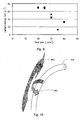
- Figure 9 shows the surface energy of a sample 112 versus the flow rate of the gas supplied by the device 200, 600 to the plasma 107.
- the distance between the sample and the location of the arc ignition was 65 mm.
- a flow-rate of approximately 20 - 25 L/min (corresponding to a gas velocity of approximately 58 - 68 m/s +/-10%) is optimal for this type of device.
- a flow-rate of 15 - 30 L/min corresponds to a rotational temperature of 2000 - 5000K, and therefore such a rotational temperature may be optimal. Therefore, a rotational temperature above approximately 2000K (i.e. 3000K +/ 10%), corresponding to a flow rate below 30 L/min (corresponding to a gas velocity of approximately 81 m/s +/- 10%), may be seen as optimal. Further, it is noted that a flow rate of approximately 40 L/min (corresponding to a gas velocity of approximately 108 m/s +/-10%) corresponds to a rotational temperature of approximately 1800K.
- the input power to the gliding arc and temperature of the set of electrodes may affect the parameters shown in figure 6 .
- Examples of values of the controlled parameters may be input power above 0.4 kW, flow rate/gas velocity lower than 81 m/s +/-10 %.
- the gliding arc may be perpendicular to the sample surface to be treated.
- the gliding arc generated by the electrodes 102 may be tilted with respect to the sample surface such that the gliding arc plasma is at a non-perpendicular angle to the sample 112.
- the gliding arc plasma 107 may be tilted an angle between 0 and 90° (preferably no less than 5 °) with respect to the sample 112 surface to be treated. This may for example be achieved by angling the set of electrodes with respect to the sample 112 surface to be treated. Thereby, the sample surface area treated increases thus increasing effectiveness of the device 100, 200, 300.
- any of the technical features and/or embodiments described above and/or below may be combined into one embodiment.
- any of the technical features and/or embodiments described above and/or below may be in separate embodiments.
- any of the technical features and/or embodiments described above and/or below may be combined with any number of other technical features and/or embodiments described above and/or below to yield any number of embodiments.
- FIG 11a-b shows a set of electrodes comprising electrode protrusions.
- Each electrode 1101 1102 comprises a tube having an approximately U shape.
- Each tube comprises a first end 1107 1109 where a coolant enters the electrode and a second end 1108 1110 where the cooling exits the electrode, where the centre of the cross section at the first end is displaced relative to the centre of the cross section at the second end.
- Each electrode comprises an electrode protrusion 1103 1104 protruding from the surface of the tubes.
- Each electrode protrusion 1103 1104 protrudes approximately towards the other electrode and/or towards the other electrode protrusion.
- Fig 11b shows a cross-section of the electrode 1102 at the plane 1105.
- the electrode 1102 comprises a circular tube having an inner shape 1106 and an outer shape 1102.
- the electrode protrusion 1103 is blade shaped.
- the electrode protrusion 1103 protrudes with a height H in the direction towards the other electrode 1101.
- the electrode protrusion 1103 has a width W in the direction perpendicular to the height in the cross section 1105.
- the protrusion has two rounded edges each having a radius of curvature of less than 3mm.
- the electrode protrusion e.g. electrode attachment
- the electrode protrusion may protrude with a height of at least 1 mm, 2 mm, 5 mm, 1 cm, 2 cm or 5 cm.
- the electrode attachment may protrude with a height no more than 10 cm, 5 cm, 2 cm, 1 cm, or 5 mm.
- the electrode protrusion e.g. electrode attachment may have a width of at least 0.1 mm, 0.2 mm, 0.5 mm, 1 mm, 1 cm or 2 cm.
- the electrode protrusion may have a width of no more than 10 cm, 5 cm, 2 cm, 1 cm, 5 mm, 2 mm, or 1 mm.
- Figure 12a-d shows different tube and electrode protrusion designs.
- Figure 13 shows an electrode comprising a tube having and electrode protrusion. Shown is a cross section of the tube being perpendicular to the longitudinal direction of the tube, at a part of the tube comprising the electrode protrusion, where the electrode protrusion has a shape such that a first surface area defined between a first line 1303 and a second line 1304 originating in the centre 1308 of said cross section is at least a factor A larger than a second surface area defined between said second line 1304 and a third line 1305 originating in said centre 1308 , wherein the angle 1306 between said first and said second line 1303 1304, and said second line 1304 and said third line 1305 is B, wherein the first and the second lines 1303 1304 are positioned so that the first surface area comprises the electrode protrusion 1302, and the third line 1305 is positioned so that the first surface area and the second surface area does not overlap.
- A may be chosen from approximately 1.1, 1.5, 2, 3, 4, 5, or 10
- B may be chosen from approximately 180 degrees, 135 degrees, 90 degrees, 45 degrees, 30 degrees, 20, degrees, 10 degrees, or 5 degrees.
- Figure 14 shows a part of an apparatus for treating a surface with a gliding arc according to an embodiment of the present invention.
- the apparatus comprises a computational unit 1401 communicatively coupled to the control unit 1403 via a first communication link 1406 and to a sensor 1402 via a second communication link 1405, wherein said sensor 1402 is adapted to measure a parameter indicative of the resistance of at least one of the electrodes, and where the computational unit 1401 is adapted to calculate a feedback signal based on the measured parameter wherein the computational unit 1401 is further adapted to transmit the feedback signal to the control unit 1403 wherein the control unit 1403 is adapted to control the cooling unit 1404 responsive to the received feed back signal such that the cooling unit 1404 is controllable via a feedback loop.
- Fig. 15 illustrates operation of an embodiment of a device for generating at least one gliding arc plasma.
- the shape and size of the electrodes 1502 facing the plasma are interesting features of the apparatus.
- the electrodes 1502 should, at least at their side facing the respective other electrode, be thin enough and/or have a radius of curvature (in a plane normal to the longitudinal direction of the electrode) small enough, and the gap between the electrodes should be small enough to ignite a discharge with low voltage.
- region 1509 different from the ignition region 1508 also referred to as region of discharge extension
- the gap between the electrodes gradually increases.
- the discharge flows in the plasma, which increases the energy.
- the gap size increases with increasing distance from the point of ignition, when a certain gap size is reached, the discharge cannot sustain the arc (equilibrium) condition and changes to a non-equilibrium plasma 1511, which is used for the processing.
- Fig. 16 illustrates a different embodiment of a device for generating at least one gliding arc plasma with electrodes 1602 having a convex shape.
- the properties and/or the shape of the gliding arc plasma may be further modified by applying magnetic field and/or any other known technologies for any specific applications.
Landscapes
- Physics & Mathematics (AREA)
- Engineering & Computer Science (AREA)
- Plasma & Fusion (AREA)
- Spectroscopy & Molecular Physics (AREA)
- Plasma Technology (AREA)
Description
- The invention relates to an apparatus for treating a surface with at least one gliding arc source. The invention further relates to a corresponding method and system.
- Non-equilibrium plasmas are preferably used for surface treatment in industry. In order to increase efficiency of the surface treatment, a gliding arc may be utilized whereby the power of the plasma may be increased by keeping the non-equilibrium condition, see e,g. A. Fridman et al., "Gliding arc discharge", Progress in Energy and Combustion Science 25, (1999), pages 211 - 231, or Kusano et al.: "Gliding are discharge: application for adhesion improvement of fibre reinforced polyester composites", Surface and Coatings Technology, vol, 202, 22-23 (2008), pages 5579-5582.
- Existing gliding arcs yield a problem that the advantages of gliding arcs are not effectively used, and thereby the resulting surface treatment effect is insufficient. For example, the extension (or length) of the discharge of prior art gliding arcs is very limited which reduces their applicability for the object with a variety of sizes and shapes.
- According to one aspect, disclosed herein is an apparatus for treating a surface with at least one gliding arc source comprising
- ■ at least one gas flow controlling unit and a set of electrodes for providing a plasma;
- ■ a cooling unit for providing a cooling fluid, and
- ■ a high voltage power supply for generating a discharge;
- Hence, an efficient cooling of the electrodes is provided while ensuring an efficient plasma generation.
- Alternatively or additionally to provide a protrusion, at least one of the electrodes may comprise a tubular portion fluidly coupled to the
cooling unit 201, wherein the electrode further comprises an outer surface comprising at least one portion facing the other one of the electrodes; wherein an intersection of said at least one portion of the outer surface of the electrode with a plane normal to a longitudinal direction of the electrode has a curvature with a radius of curvature less than 3mm. For example, the tubular portion may define said longitudinal direction. Said portion of the outer surface may thus be curved in a plane normal to said longitudinal direction and have a radius of curvature smaller than 3mm, preferably smaller than 2mm. - For example the electrode may be formed as a tube having a radius no larger than 3mm. Alternatively, the electrode may comprise a tubular portion, e.g. a tubular portion with a radius no less than 3mm, and a protrusion extending radially from the tubular portion where the protrusion has a radially outward edge portion. The edge portion may be curved in a plane normal to said longitudinal direction and have a radius of curvature smaller than 3mm, preferably smaller than 2mm.
- According to another aspect, disclosed herein is an apparatus for treating a surface with at least one gliding arc source comprising
- at least one gas flow controlling unit and a set of electrodes for providing a plasma;
- a cooling unit for supplying a cooling fluid;
- a high voltage power supply for generating a discharge
- a control unit adapted to control at least the cooling unit;
- a sensor adapted to measure a parameter indicative of the resistance of at least one of the electrodes,
- a computational unit communicatively coupled to the sensor;
- Hence, an efficient control of the electrodes is provided while ensuring an efficient plasma generation.
- According to yet another aspect, disclosed herein is an apparatus for treating a surface with at least one gliding arc source comprising at least one gas flow controlling unit for each gliding arc source; and a set of electrodes; wherein the at least one gas flow controlling unit and the set of electrodes are controlled to provide a plasma comprising a rotational temperature at the point of arc ignition above approximately 2000K and more preferably above 3000K.
- Thereby is achieved a plasma with an optimal or substantially optimal plasma for treating surfaces of samples.
- Embodiments of the present invention also relates to a method corresponding to embodiments of the device.
- More specifically, according to one aspect, the invention relates to a method of treating a surface with at least one gliding arc source comprising controlling at least one gas flow controlling unit and controlling a set of electrodes; and providing a plasma via the at least one gas flow controlling unit and the set of electrodes; and controlling the plasma to comprise a rotational temperature at the point of arc ignition above approximately 2000K and more preferably 3000K.
- The method and embodiments thereof correspond to the device and embodiments thereof and have the same advantages for the same reasons.
- Embodiments of the present invention also relate to a system corresponding to embodiments of the device.
- More specifically, the invention relates to a system for treating a surface with at least one gliding arc source comprising an apparatus according to an embodiment of the invention and a sample, wherein the apparatus is adapted to provide a plasma to treat the sample surface.
- In some embodiments, at least one of the electrodes comprises a tube having a first end and a second end wherein the tube is configured to receive, during operation a coolant at said first end and discharge the coolant at said second end, wherein the centre of the cross-section of the tube at the first end is displaced relative to the centre of the cross-section of the tube at the second end.
- The cross section of the tube may have any shape such as round or rectangular. The cross section of the tube may have a width between 1 mm and 50 cm, between 0.5 cm and 20 cm, between 1 cm and 10 cm or between 2 cm and 8 cm. The cross section of the tube includes a portion facing the other electrode and the plasma. At least a part of this portion may be curved with a radius of curvature less than 3mm, e.g. les than 2mm. Both electrodes may comprise a tube.
- The tube may have approximately a U shape where the first end and the second end are positioned at the upper part of the U approximately at the same height.
- Consequently, an electrode is provided capable of being efficiently cooled by circulating coolant. The flow resistance is lowered allowing an even better cooling by designing the electrode as a tube with a larger inner diameter.
- In some embodiments, at least one of the electrodes comprises a tubular portion wherein the tubular portion, at least along a portion of its outer surface, comprises a protrusion configured to lower the needed voltage applied to the electrodes to ignite the plasma, relatively to the needed voltage when the at least one electrode does not comprise said protrusion.
- The protrusion may be an elongated, flat, e.g. blade-shaped, element elongated along the longitudinal direction of the electrode and having a width at an end distal to the electrode, which width is smaller than its longitudinal dimension and smaller than the height of the protrusion. Generally, the protrusion may extend along at least a portion of the outer surface of the tubular portion. The protrusion may project from the outer surface of the tubular portion towards the other electrode and the plasma, thus defining at least one edge portion facing the other electrode. The edge portion may be round and have a radius of curvature less than 3mm, e.g. less than 2mm. The radius of curvature may be measured in an intersection of the protrusion with a cross-sectional plane of the electrode normal to the longitudinal direction of the electrode.
- The electrode protrusion e.g. electrode attachment, may protrude in a direction approximately towards the other electrode. The electrode protrusion may protrude with a height of at least 1 mm, 2 mm, 5 mm, 1 cm, 2 cm, 5 cm, or 10 cm. The electrode attachment may protrude with a height no more than 20 cm, 10 cm, 5 cm, 2 cm, 1 cm, or 5 mm.
- The electrode protrusion may have a shape such that the intensity of the electric field around the part of the electrode comprising the protrusion is increased relatively to the intensity of electrical field of the same part of the electrode if the protrusion where removed, when a voltage is applied, whereby the voltage needed to ignite the plasma is lowered.
- The electrode protrusion may be attached to the tubular portion after the tubular portion is formed or the tubular portion and the attachment may be formed as an integral body. It will further be appreciated that more than one protrusion, e.g. more than one attachment, may be provided at each electrode.
- In some embodiments, the attachment, the blades and/or the protrusion may be directly cooled by circulating fluid.
In some embodiments, a cross section of the tubular portion being perpendicular to the longitudinal direction of the tubular portion, comprising a part of the electrode protrusion, may have a shape such that a first surface area defined between a first line and a second line originating in the centre of said cross section is at least a factor A larger than a second surface area defined between said second line and a third line originating in said centre, wherein the angle between said first and said second line, and said second line and said third line is B, wherein the first and the second line is positioned so that the first surface area comprises the electrode protrusion, and the third line is positioned so that the first surface area and the second surface area do not overlap. - A may be chosen from approximately 1.1, 1.5, 2, 3, 4, 5, or 10, and B may be chosen from approximately 180 degrees, 135 degrees, 90 degrees, 45 degrees, 30 degrees, 20, degrees, 10 degrees, or 5 degrees.
- In some embodiments, the apparatus further comprises a computational unit communicatively coupled to the control unit via a first communication link and to a sensor via a second communication link, wherein said sensor is adapted to measure a parameter indicative of the resistance of at least one of the electrodes, and where the computational unit is adapted to calculate a feedback signal based on the measured parameter wherein the computational unit is further adapted to transmit the feedback signal to the control unit wherein the control unit is adapted to control the cooling unit responsive to the received feed back signal such that the cooling unit is controllable via a feedback loop. Additionally or alternatively, the computational unit may be adapted to calculate a feedback signal based on the measured parameter wherein the computational unit is further adapted to feed the feedback signal to the control unit wherein the control unit is adapted to control the power supply responsive to the received feedback signal such that the power supply is controllable via a feedback loop.
- The parameter may be the temperature of the electrode, or the resistance of the electrode. The temperature of the electrode may be measured by attaching a temperature sensor to the electrode and/or measuring the Infra red and/or visible radiation from the electrode. The temperature of the electrodes may also be estimated by the temperatures of the fluid (coolant) before and after cooling the electrodes, or by measuring the temperature of the
sample 112. The feedback signal may be generated securing that the resistance of the electrode is maintained below a predetermined value e.g. two or three times larger resistance than the resistance at room temperature, if the temperature of the electrode increases the feedback signal may secure that cooling unit cools the electrode more e.g. by increasing the flow rate of the coolant and/or decreasing the temperature of the coolant. Correspondingly, if the temperature of electrode decreases the feedback signal may cause the cooling unit to cool the electrode less e.g. by decreasing the flow rate of the coolant and/or increasing the temperature of the coolant. As the resistance and the temperature of an electrode normally have an approximately linear relationship the feedback signal may be generated securing that the temperature of the bulk part of the electrode is not raised with more than 3/α from room temperature (e.g. from 20 degrees Celsius), where α is the temperature coefficient of the linear relationship between the resistance and temperature. For copper and aluminium 3/α is approximately 769 degrees Celsius, and for tungsten it is 667 degrees Celsius. The feedback signal may be generated securing that the temperature of the electrode is not raised with more than 2/α from room temperature, where α is the temperature coefficient of the linear relationship between the resistance and temperature. For copper and aluminium 2/α is approximately 513 degrees Celsius, for tungsten it is 444 degrees Celsius, and for stainless steel it is 2000 degrees Celsius. The feedback signal may be generated securing that the temperature of the electrode is not raised with more than 1/α from room temperature, where α is the temperature coefficient of the linear relationship between the resistance and temperature. For copper and aluminium 1/α is approximately 256 degrees Celsius, for tungsten it is 222 degrees Celsius, and for stainless steel it is 1000 degrees Celsius. -
-
Figure 1 shows an embodiment of a device for generating at least one gliding arc plasma. -
Figure 2 shows an embodiment of a device for generating at least one gliding arc plasma and comprising a cooling unit. -
Figure 3 shows an embodiment of a device for generating at least one gliding arc plasma comprising a control unit. -
Figure 4 shows an embodiment of a set of electrodes in which the electrodes are formed as hollow tubes. -
Figure 5 shows an embodiment of a set of electrodes comprising hollow tube electrodes with blades. -
Figure 6 shows the O/C ratio at the surface of a polyester sample after plasma treatment for a number of devices. -
Figure 7 shows how parameters controlled by the device affect parameters of the plasma and a sample treated by the plasma. -
Figure 8 shows an embodiment of adevice 600 comprising a feedback loop for optimizing control of aplasma 107. -
Figure 9 shows the polar component of the surface energy of a polyester sample versus the flow rate of the gas (air) supplied by the device to the plasma. -
Figure 10 shows a definition of axial and circumferential curvatures. -
Figure 11a-b shows a set of electrodes comprising electrode protrusions. -
Figure 12a-d shows different tube and electrode protrusion designs. -
Figure 13 shows an electrode comprising a tube having and electrode protrusion. -
Figure 14 shows a part of an apparatus for treating a surface with a gliding arc according to an embodiment of the present invention. -
Figure 15 shows an embodiment of a device for generating at least one gliding arc plasma. -
Figure 1 shows an embodiment of adevice 100 for generating at least onegliding arc plasma 107 such as one gliding arc plasma or a plurality of gliding arc plasmas. Thedevice 100 may comprise a gasflow controlling unit 104, a set ofelectrodes 102 and apower supply 101. - The gas
flow controlling unit 104 may be exemplified as a needle valve, which is able to regulate the flow, or a float type flow meter, which is able to regulate the flow and measure the flow, or a mass flow controller, which is able to regulate the flow via an external electric signal and to measure the flow. - In an embodiment, the gas
flow controlling unit 104 may comprise a plurality of flow meters such as a flow meter for each gas component in a multiple component gas mixture. For example, the gasflow controlling unit 104 may comprise two flow meters when providing a two component gas mixture to theplasma 107, one flow meter for each component in a two component gas mixture. - The gas flow controlling unit and the power supply may be electrically coupled to the electric grid e.g. via respective electric wires. Thereby the electric grid may provide power to the gas flow controlling unit and to the
power supply 101. - The
power supply 101 may be electrically connected to the set ofelectrodes 102 e.g. viaelectrical wires 113. Generally, the voltage required may depend on e.g. the gap between the electrodes. If the gap is smaller, the ignition voltage is also smaller. In some embodiments the power supply may be configured to supply a voltage between 300 V and 40 kV. The operation of the arc requires normally requires much lower voltages than the ignition of the plasma. - Via the
electrical wires 113, thepower supply 101 may provide (electric) energy to the set ofelectrodes 102. For example, thepower supply 101 may be connected to the electrical grid from where thepower supply 101 may receive electric energy. Additionally, thepower supply 101 may transform the power, e.g. alternating current, received from the electric grid into a format suitable for the set of electrodes, e.g. direct current or alternating current. Thereby, the set ofelectrodes 102 may generate a gliding arc using either direct current (DC) or alternating current (AC). The driving frequency of the alternating current may be between 5 Hz and 2 MHz, preferably between 50 Hz and 500 kHz. - The
power supply 101 may additionally control the surface temperature of asample 112 to be treated by the at least onegliding arc plasma 107. By increasing the power from thepower supply 101 to the set ofelectrodes 102, the surface temperature of the sample may be increased. - The gas
flow controlling unit 104 may inject gas into aplasma 107 contained in a volume. Alternatively, a plasma may be created in the volume. In the above and below, aplasma 107 may be characterized as a partially ionized gas, in which a certain proportion of electrons are free rather than being bound to an atom or a molecule in the gas. The ability of positive and negative charges to move somewhat independently makes the plasma electrically conductive so that it responds strongly to electromagnetic fields. Examples of suitable gases to be fed to the discharge for use in embodiments of an apparatus described herein include air, N2, O2, Ar, He, Ne, CO2, H2O, hydro-carbons (such as methane, ethane, propane, butane, alcohols, etc.), etc. or mixtures of the above. - For example, the gas
flow controlling unit 104 may inject a gas into the plasma as indicated by thearrow 194. The volume containing the plasma may be partly or wholly expanded by the set ofelectrodes 102 and thegas flow 194. - The gas
flow controlling unit 104 may be controlled manually by a person setting the flow rate of the gas injected into theplasma 107. - The set of
electrodes 102 may, for example, comprise two electrodes having a radius of axial curvature. For example, the radius ofaxial curvature 901 may be at least approximately 20 mm (more preferably > 40 mm). Alternatively, the set of electrodes may comprise two straight electrodes. Further, the two electrodes may be positioned with a distance between approximately 0.2 mm and 20 mm (preferably 0.2 mm and 10 mm) between them at the point of minimal distance. Generally, the point of minimum distance between the electrodes corresponds to the point of ignition. However, if there is a sharply edged part of the electrode with a slightly larger gap, this may be the point of ignition. The ignition generally occurs only if the electric field is strong enough, i.e. the point of ignition is generally a location along the electrode where the electrical field between the electrodes is sufficiently strong. - In an embodiment, the set of
electrodes 102 may comprise more than two electrodes e.g. three or four electrodes. - Large voltage differences (e.g.1-40 kV) between the electrodes induce ignition of an arc discharge. The arc discharge is extended by a high speed gas flow from the gas
flow controlling unit 104. The input power, provided by thepower supply 101, of the arc can be high e.g. in the order of 0,2 - 5 kW per one gliding arc. Thereby, the input power to the at least one gliding arc plasma may be controlled such that electrons in the at least one gliding arc have high temperature, e.g. above 0.5 eV. -
Figure 2 shows an embodiment of adevice 200 for generating at least onegliding arc plasma 107 such as one gliding arc plasma or a plurality of gliding arc plasmas. Thedevice 200 may comprise the technical features offigure 1 . - In the
device 200, each electrode in the set of electrodes may be hollow enabling passage of a fluid through the set of electrodes. - Additionally, the
device 200 may comprise acooling unit 201. The cooling unit may be fluidly coupled to the set ofelectrodes 102 e.g. via atube 202 or the like. Thereby, thecooling unit 201 may cool the set ofelectrodes 102 e.g. by pumping a coolant through the set ofelectrodes 102 via thetube 202. - The
cooling unit 201 may be electrically coupled to thepower supply 101 via an electric wire 204 or to an electric grid (not shown). - In an embodiment, the
device 200 may further comprise anactuator 110 adapted to translate asample 112 through theplasma 107. For example, theactuator 110 may comprise an X-Y-table. Theactuator 110 may be controlled manually by an operator. - Optionally, the X-Y-table of the
actuator 110 may be hollow enabling a fluid to pass through theactuator 110. In this case, thecooling unit 201 may be fluidly coupled to theactuator 110 e.g. via atube 203 or the like. Thereby, thecooling unit 201 is able to cool the actuator 110 by pumping a coolant such as water through theactuator 110. - As in
figure 1 , thedevice 200 is able to generate aplasma 107 and to surface treat asample 112. -
Figure 3 shows an embodiment of adevice 300 for generating at least onegliding arc plasma 107 such as one gliding arc plasma or a plurality of gliding arc plasmas. Thedevice 300 may comprise apower supply 101, acontrol unit 103, at least one gas flow controlling unit 104 (e.g. one gas flow controlling unit) and a set ofelectrodes 102. - The
power supply 101 may be electrically communicated with thecontrol unit 103 e.g. via anelectrical wire 105, such that thecontrol unit 103 may control thepower supply 101. - The
control unit 103 may control the power provided to the at least one gasflow controlling unit 104 e.g. viaelectric wire 113. - For example, the set of
electrodes 102 may be electrically coupled to thepower supply 101 via e.g. anelectric wire 106, and communicatively coupled to thecontrol unit 103 via a wireless and/or wiredcommunication link 106. The communication link may be established via e.g. an electrical wire and/or Bluetooth. Thereby, via theelectric wire 105, thecontrol unit 103 may control the frequency and/or the amplitude of the power supplied to the set ofelectrodes 102, and via theelectric wire 106, the power supply may provide power to the set ofelectrodes 102. - Additionally, the
control unit 103 may control the at least one gasflow controlling unit 104. The at least one gasflow controlling unit 104 may be communicatively coupled to thecontrol unit 103 e.g. by a wireless and/or wiredcommunication link 113. The communication link may be established via an electrical wire and/or Bluetooth. Thereby, thecontrol unit 103 may control the amount of gas and/or the flow rate of gas injected by the at least one gasflow controlling unit 104. Thereby, thecontrol unit 103 may comprise controlling flow of the gas used in theplasma 107 and thus, for example, the gas in the plasma may be cooled while the electron temperature is substantially maintained e.g. within +/- 30 %. - The at least one gas
flow controlling unit 104 may inject gas into aplasma 107 contained in a volume via the set ofelectrodes 102. Alternatively, a plasma may be created in the volume. In the above and below, aplasma 107 may be characterized as a partially ionized gas, in which a certain proportion of electrons are free rather than being bound to an atom or a molecule in the gas. The ability of positive and negative charges to move somewhat independently makes the plasma electrically conductive so that it responds strongly to electromagnetic fields. - The set of
electrodes 102 may, for example, comprise two or more electrodes having a radius of axial curvature. For example, the radius of axial curvature (see 901 infigure 10 for a definition of axial curvature) may be approximately more than 20mm (preferably > 40 mm). Alternatively, the set of electrodes may comprise two straight electrodes. Further, the two electrodes may be positioned with a distance between approximately 0,2 mm and 20 mm (preferably 0.2 mm and 10 mm) between them at the point of minimal distance. - Large voltage differences (e.g. 1-40 kV) between the electrodes induces ignition of an arc discharge. The arc discharge is extended by a high speed gas flow. The input power of the arc can be high e.g. in the order of 0,2 - 5 kW per one gliding arc. Thereby, the input power to the at least one gliding arc plasma may be controlled such that electrons in the at least one gliding arc have high temperature, e.g. above 0,5 eV. Thereby, the
control unit 103 may be adapted to control the input power to the at least one gliding arc plasma via the set ofelectrodes 102 such that electrons in the at least one gliding arc have high temperature, e.g. above 0,5 eV, and such that the energy density in the at least one gliding arc is high (typically at least 200 W, preferably at least 400 W). - In an embodiment, the
device 300 may further comprise acooling unit 201 which may be controlled by thecontrol unit 103. For example, thecooling unit 201 may be communicatively coupled to thecontrol unit 103 e.g. by a wireless and/or wiredcommunication link 109 such as an electrical wire and/or Bluetooth. - The
cooling unit 201 may be fluidly connected to the set ofelectrodes 102 via e.g. atube 202 or the like. Theelectrodes 102 may be hollow to enable a fluid to pass through them. Thereby, thecooling unit 201 may be adapted to provide a coolant to the set ofelectrodes 102. The coolant may, for example, be water, oil or air. Generally, the coolant may be an insulating fluid and/or a fluid with high resistance. Generally, in some embodiments a gas may be fed through the tubes of the electrodes for cooling, and all or a part of the gas may subsequently be fed to the plasma. - The
cooling unit 201 may optionally be fluidly connected to the X-Y table 110 via atube 203. - In an embodiment, the
device 300 may further comprise anactuator 110 adapted to translate asample 112 through theplasma 107. For example, theactuator 110 may comprise an X-Y-table. Theactuator 110 may be communicatively coupled to thecontrol unit 103 e.g. by a wireless and/or wiredcommunication link 111 such as an electrical wire and/or Bluetooth. Thereby, thecontrol unit 103 is adapted to control theactuator 110 such as for example the speed by which thesample 112 is translated through theplasma 107. -
Figure 4 shows an embodiment of a set ofelectrodes 102 in which theelectrodes 102 are formed as hollow tubes enabling a fluid to circulate within them. Thehollow electrodes 102 may be fluidly connected to thecooling unit 201 so as to enable the coolant to be circulated in theelectrodes 102. Thereby, thecontrol unit 103 offigure 3 may be adapted to control the temperature of the electrodes by circulating the coolant in the hollow set ofelectrodes 102. - In an embodiment, the hollow tubes of the
electrodes 102 may be thin, for example having an outer diameter of 3 mm and an inner diameter of 2 mm. Thin electrodes may provide a more efficient use of the power supplied from thepower supply 101 to the electrodes because if the point of arc ignition is sharply edged, the intensity of the electric field generated by the electrodes is higher, and a discharge, ignited by the electrodes, is ignited with a lower voltage. Generally the radius of curvature of the portion of the surface (measured in a plane normal to the longitudinal direction of the electrode, also referred to as circumferential curvature) at the point of arc ignition should be no more than 3mm. - Alternatively or additionally, if the circumferential curvature (see 902 in
figure 10 for a definition of circumferential curvature) of the electrodes is small, the intensity of the electric field generated by the electrodes is also higher, and the discharge, ignited by the electrodes, is ignited with a lower voltage. - Generally, a
power supply 101 may provide a higher power if the required voltage is lower. Therefore, by using thin electrodes, a givenpower supply 101 may provide a higher power than if thick electrodes are used. - Additionally, as the cost of a
power supply 101 increases with the maximum deliverable power in the specification, it may be desirable to reduce the required voltage which may be achieved using thin electrodes. - In an embodiment, the hollow tubes of the
electrodes 102 may be thick, for example having an outer diameter of 6 mm and an inner diameter of 4 mm. Increasing the inner diameter of the hollow set ofelectrodes 102 may enable more efficient cooling due to the possibility of using a higher coolant flow rate in a tube with a larger inner diameter. More efficient cooling enables a higher electric energy to be delivered to the plasma than the thinner electrodes because the resistance of the electrodes increases with temperature, and thus the resistance of the thick electrodes, which are better cooled, is smaller than the thin electrodes. When the resistance is higher, more electrical energy is consumed for heating. Thereby, a higher plasma energy may be achieved which may result in better surface treatment. - In an embodiment, one electrode may be thick and one electrode may be thin.
-
Figure 5 shows an embodiment of a set ofelectrodes 102 comprisingattachments 301. Theattachments 301 may, for example, be blade-shaped. By includingattachments 301 in theelectrodes 102, the voltage required for generating the plasma may be reduced as disclosed above under thin electrodes. Thus, the voltage required for generating a plasma using thick electrodes may be lowered by includingattachments 301. - In an embodiment, the attachments are rigidly coupled to the electrodes e.g. via welding or the like.
- The
blades 301 may be made of the same material as theelectrodes 102 e.g. copper or aluminum, stainless steel, tungsten or the like. The blades 401 may be welded to theelectrodes 102 or theelectrodes 102 andblades 301 may be cast into a single piece. Alternatively, the blades may be made of a different material than the electrodes. - In an embodiment, the
blades 301 may be included in a hollow set of electrodes i.e. electrodes through which the coolant may be circulated. Optionally, theblades 301 may also be hollow and fluidly connected to the hollow set ofelectrodes 102, e.g. via one or more holes, thereby enabling coolant to circulate through the blades and thus enabling cooling of theblades 301. - Generally, the
blades 301 may be designed such that they enable a lowering of the ignition voltage for the plasma, whereby a condition comprising a high electron temperature (e.g. greater than 0,5 eV) and a high input power to at least one gliding arc (e.g. greater than 0,2 kW and below 5 kW) may be established. The design of the attachments may include using sharp edged blades and/or blades with a small radius of curvature (i.e. small diameter no more than 4 mm (if radius no more than 2 mm)) so that high electric field can be generated at theelectrodes 301. - Additionally or alternatively, the electrodes may be designed to include sharp edged and/or a small radius of curvature (i.e. small diameter) so that a high electric field can be generated at the
electrodes 102. - The sharp edges of the
attachments 301 and/or the electrodes may ensure a low ignition voltage, thereby enabling a high energy input to theplasma 107. -
Figure 6 shows the atomic composition at the surface of apolyester sample 112 after treatment with a prior art device represented by solid diamonds, a device according toFigure 4 comprising thin tubes (in order to achieve a low ignition voltage) represented by open squares, and a device according tofigure 4 , thick tubes and blades (in order to achieve a low ignition voltage and a low resistance in the electrodes) represented by solid triangles, measured by means of x-ray photoelectron spectroscopy. When the oxygen to carbon ratio (O/C ratio) increases, it is an indication of better performance of a device due to more oxygen from the plasma having reacted with the plastic of thesample 112. Thus, fromfigure 6 it is seen that the gliding arc plasma system with blades is most efficient in oxidizing the polyester surfaces of theplastic sample 112. Further, it is seen that the gliding arc plasma system comprising cooled electrodes is more efficient than the prior art device. -
Figure 7 shows how parameters controlled by thedevice plasma 107 and asample 112 treated by the plasma. - For example, if the
control unit 103 increases the power applied to theelectrodes 102, then the energy density of theplasma 107 increases and therefore, thedevice sample 112 through theplasma 107 in order to treat thesample 112. - Further, increasing the power applied to the
electrodes 102 provides for a higher electron temperature in the plasma and higher plasma density and thereby a faster treatment of thesample 112 surface. - If the at least one gas
flow controlling unit 104 is able to provide a suitable gas flow to theplasma 107, thedevice plasma 107. When the flow rate is increased, the gas and electrons are cooled more at and around the arc ignition point e.g. within a perimeter of e.g. a radius of 20 mm around the arc ignition point. The electron temperature may remain substantially (e.g. within 30 %) unchanged beyond this perimeter, while the gas temperature decreases furthermore beyond the perimeter. - Additionally, by having the at least one gas
flow controlling unit 104 providing a suitable gas flow, thedevice - The gas flow rate has to be low enough to sustain a high temperature of the arc discharge. Further, by providing a high gas flow, corrosion of the electrodes may be impeded or prevented.
- If the
cooling unit 201 increases cooling of theelectrodes 102, then the electrical resistance of the electrodes decreases. Thereby is achieved that a higher power may be applied to theelectrodes 102 without risking damaging theelectrodes 102. Further, lower resistance results in lower power loss. - Further, by cooling the
electrodes 102, the surface temperature of thesample 112 may be controlled. By cooling theelectrodes 102, low thermal damage to thesample 112 being treated is achieved because thermal radiation from the electrodes to thesample 112 is reduced. - The
actuator 110 may control the surface temperature of thesample 112. If theactuator 110 increases the speed of thesample 112 through theplasma 107, low thermal damage to thesample 112 may be achieved because an irradiated part of thesample 112 may cool down while another part of thesample 112 subsequently becomes irradiated. - The surface temperature of the
sample 112 may be controlled by changing the distance between the sample and the at least one gliding arc source. - The temperature of the
sample 112 may be decreased by placing the sample on a cooled sample holder. -
Figure 8 shows an embodiment of adevice 600 comprising a feedback loop for optimizing control of aplasma 107. - The temperature of the gas in the
plasma 107 may be estimated using the rotational temperature obtained from optical emission (e.g. OH emission) in the gas e.g. as disclosed in C. O. Laux, T. G. Spence, C. H. Kruger, and R. N. Zare, "Optical diagnostics of atmospheric pressure air plasmas", Plasm. Source Sci. Technol. 12 (2003), p 125-138. - The rotational temperature may be detected by an
optical detector 602 by observing the optical emission from theplasma 107. - In an embodiment, the
device 600 comprises acomputational unit 605 adapted to analyze the rotational spectrum. - The
computational unit 605 may be communicatively connected to theoptical detector 602 and thecontrol unit 103 of thedevice 200 via respective wired and/orwireless communication links - The
computational unit 605 may receive a rotational spectrum from theoptical detector 602 viaconnection 606, e.g. via an electrical wire. Based on the rotational spectrum received, thecomputational unit 605 may estimate a rotational temperature. - The rotational temperature may be representative of the molecule/gas temperature in the
plasma 107, and thus, thecomputational unit 605 may be adapted to determine a temperature of the gas (ions and/or molecules) in the plasma based on the rotational temperature. - Based on the estimated gas temperature in the plasma, the
computational unit 605 may be adapted to transmit a feedback signal to thecontrol unit 103 of thedevice 200 viacommunication link 607 in order to e.g. have thecontrol unit 103 to increase the gas flow to theplasma 107 via the at least one gasflow controlling unit 104 and/or to increase the electric current in the electrodes, etc., in order to optimize theplasma 107 according to predetermined plasma values stored in thecomputational unit 107 e.g. a rotational temperature of 2000K at a flow rate of 30 L/min (corresponding to a gas velocity of 81 m/s +/-10%). - Further, the rotational temperature may be representative of the electron temperature at the arc of the electrodes and therefore, the
computational unit 605 may be adapted to determine the electron temperature at the arc of the electrodes based on the rotational temperature. -
Figure 9 shows the surface energy of asample 112 versus the flow rate of the gas supplied by thedevice plasma 107. Infigure 9 , the distance between the sample and the location of the arc ignition was 65 mm. The higher the polar component of the surface energy of thesample 112 the better for adhesion, because more amounts of polar functional groups are created, which efficiently interact with adhesives. Thus, fromfigure 9 it is seen that a flow-rate of approximately 20 - 25 L/min (corresponding to a gas velocity of approximately 58 - 68 m/s +/-10%) is optimal for this type of device. A flow-rate of 15 - 30 L/min (corresponding to a gas velocity of approximately 41 - 81 m/s +/- 10%) corresponds to a rotational temperature of 2000 - 5000K, and therefore such a rotational temperature may be optimal. Therefore, a rotational temperature above approximately 2000K (i.e. 3000K +/ 10%), corresponding to a flow rate below 30 L/min (corresponding to a gas velocity of approximately 81 m/s +/- 10%), may be seen as optimal. Further, it is noted that a flow rate of approximately 40 L/min (corresponding to a gas velocity of approximately 108 m/s +/-10%) corresponds to a rotational temperature of approximately 1800K. - Besides the flow rate, other parameters which may be controlled are the input power to the gliding arc and temperature of the set of electrodes. These parameters (flow rate, input power and temperature) may affect the parameters shown in
figure 6 . Examples of values of the controlled parameters may be input power above 0.4 kW, flow rate/gas velocity lower than 81 m/s +/-10 %. Additionally, the temperature of the bulk part of the electrode may be defined using the temperature coefficient α of the electrode material, Assuming that maximum acceptable resistance of the bulk part of the electrodes is 2 times that of room temperature, the maximum acceptable temperature is approximately 1/α degree. For example, if the electrode is made of copper, α = 0.393 % per degree C and thus the maximum acceptable temperature is approximately 254 degree C. - In an embodiment, the gliding arc may be perpendicular to the sample surface to be treated.
- In an embodiment, the gliding arc generated by the
electrodes 102 may be tilted with respect to the sample surface such that the gliding arc plasma is at a non-perpendicular angle to thesample 112. For example, the glidingarc plasma 107 may be tilted an angle between 0 and 90° (preferably no less than 5 °) with respect to thesample 112 surface to be treated. This may for example be achieved by angling the set of electrodes with respect to thesample 112 surface to be treated. Thereby, the sample surface area treated increases thus increasing effectiveness of thedevice - In general, any of the technical features and/or embodiments described above and/or below may be combined into one embodiment. Alternatively or additionally any of the technical features and/or embodiments described above and/or below may be in separate embodiments. Alternatively or additionally any of the technical features and/or embodiments described above and/or below may be combined with any number of other technical features and/or embodiments described above and/or below to yield any number of embodiments.
-
Figure 11a-b shows a set of electrodes comprising electrode protrusions. Eachelectrode 1101 1102 comprises a tube having an approximately U shape. Each tube comprises afirst end 1107 1109 where a coolant enters the electrode and asecond end 1108 1110 where the cooling exits the electrode, where the centre of the cross section at the first end is displaced relative to the centre of the cross section at the second end. Each electrode comprises anelectrode protrusion 1103 1104 protruding from the surface of the tubes. Eachelectrode protrusion 1103 1104 protrudes approximately towards the other electrode and/or towards the other electrode protrusion.Fig 11b shows a cross-section of theelectrode 1102 at theplane 1105. Theelectrode 1102 comprises a circular tube having aninner shape 1106 and anouter shape 1102. Theelectrode protrusion 1103 is blade shaped. Theelectrode protrusion 1103 protrudes with a height H in the direction towards theother electrode 1101. Theelectrode protrusion 1103 has a width W in the direction perpendicular to the height in thecross section 1105. Infig. 11 b the protrusion has two rounded edges each having a radius of curvature of less than 3mm. - The electrode protrusion e.g. electrode attachment, may protrude with a height of at least 1 mm, 2 mm, 5 mm, 1 cm, 2 cm or 5 cm. The electrode attachment may protrude with a height no more than 10 cm, 5 cm, 2 cm, 1 cm, or 5 mm.
- The electrode protrusion e.g. electrode attachment, may have a width of at least 0.1 mm, 0.2 mm, 0.5 mm, 1 mm, 1 cm or 2 cm. The electrode protrusion may have a width of no more than 10 cm, 5 cm, 2 cm, 1 cm, 5 mm, 2 mm, or 1 mm.
-
Figure 12a-d shows different tube and electrode protrusion designs. -
Figure 13 shows an electrode comprising a tube having and electrode protrusion. Shown is a cross section of the tube being perpendicular to the longitudinal direction of the tube, at a part of the tube comprising the electrode protrusion, where the electrode protrusion has a shape such that a first surface area defined between afirst line 1303 and asecond line 1304 originating in thecentre 1308 of said cross section is at least a factor A larger than a second surface area defined between saidsecond line 1304 and athird line 1305 originating in saidcentre 1308 , wherein theangle 1306 between said first and saidsecond line 1303 1304, and saidsecond line 1304 and saidthird line 1305 is B, wherein the first and thesecond lines 1303 1304 are positioned so that the first surface area comprises theelectrode protrusion 1302, and thethird line 1305 is positioned so that the first surface area and the second surface area does not overlap. - A may be chosen from approximately 1.1, 1.5, 2, 3, 4, 5, or 10, and B may be chosen from approximately 180 degrees, 135 degrees, 90 degrees, 45 degrees, 30 degrees, 20, degrees, 10 degrees, or 5 degrees.
-
Figure 14 shows a part of an apparatus for treating a surface with a gliding arc according to an embodiment of the present invention. The apparatus comprises acomputational unit 1401 communicatively coupled to thecontrol unit 1403 via afirst communication link 1406 and to asensor 1402 via asecond communication link 1405, wherein saidsensor 1402 is adapted to measure a parameter indicative of the resistance of at least one of the electrodes, and where thecomputational unit 1401 is adapted to calculate a feedback signal based on the measured parameter wherein thecomputational unit 1401 is further adapted to transmit the feedback signal to thecontrol unit 1403 wherein thecontrol unit 1403 is adapted to control thecooling unit 1404 responsive to the received feed back signal such that thecooling unit 1404 is controllable via a feedback loop. -
Fig. 15 illustrates operation of an embodiment of a device for generating at least one gliding arc plasma.The shape and size of theelectrodes 1502 facing the plasma are interesting features of the apparatus. At the point ofdischarge ignition 1508, theelectrodes 1502 should, at least at their side facing the respective other electrode, be thin enough and/or have a radius of curvature (in a plane normal to the longitudinal direction of the electrode) small enough, and the gap between the electrodes should be small enough to ignite a discharge with low voltage. In theregion 1509 different from the ignition region 1508 (also referred to as region of discharge extension), the gap between the electrodes gradually increases. As long as the discharge bridges the electrodes, the current flows in the plasma, which increases the energy. As the gap size increases with increasing distance from the point of ignition, when a certain gap size is reached, the discharge cannot sustain the arc (equilibrium) condition and changes to anon-equilibrium plasma 1511, which is used for the processing. -
Fig. 16 illustrates a different embodiment of a device for generating at least one gliding arc plasma withelectrodes 1602 having a convex shape. - It will be appreciated that, in some embodiments of the apparatus described herein, the properties and/or the shape of the gliding arc plasma may be further modified by applying magnetic field and/or any other known technologies for any specific applications.
- Although some embodiments have been described and shown in detail, the invention is not restricted to them, but may also be embodied in other ways within the scope of the subject matter defined in the following claims. In particular, it is to be understood that other embodiments may be utilised and structural and functional modifications may be made without departing from the scope of the present invention.
- In device claims enumerating several means, several of these means can be embodied by one and the same item of hardware. The mere fact that certain measures are recited in mutually different dependent claims or described in different embodiments does not indicate that a combination of these measures cannot be used to advantage.
- It should be emphasized that the term "comprises/comprising" when used in this specification is taken to specify the presence of stated features, integers, steps or components but does not preclude the presence or addition of one or more other features, integers, steps, components or groups thereof.
Claims (14)
- An apparatus for treating a surface with a at least one gliding arc source comprising■ a at least one gas flow controlling unit (104) and a set of elongated electrodes (102) for providing a plasma;■ a cooling unit (201) for providing a cooling fluid, and■ a high voltage power supply (101) for generating a dischargewherein at least one of the electrodes (102) comprises a tubular portion fluidly coupled to the cooling unit (201) wherein the tubular portion defines a longitudinal direction of the electrode, wherein the electrode (102) further comprises an outer surface comprising a portion facing the other one of the electrodes (102) said portion of the outer surface being curved in a plane normal to said longitudinal direction.
- An apparatus according to claim 1, wherein said portion of the outer surface being curved in a plane normal to said longitudinal direction is having a radius of curvature less than 3mm.
- An apparatus according to claim 1 or 2, wherein the tubular portion comprises, at least along a portion of its outer surface, a protrusion configured to lower the voltage applied to the electrodes (102) required to ignite the plasma, said protrusion comprising said portion of the outer surface.
- An apparatus according to claim 3, wherein each electrode of the set of electrodes (102) comprises a protrusion.
- An apparatus according to claim 3 or 4, wherein the protrusion is blade-shaped.
- An apparatus according to anyone of claims 3 to 5, wherein the protrusion is hollow and fluidly coupled to the cooling unit (201) via the said tubular portion.
- An apparatus according to anyone of claims 1 to 6, wherein at least one of the electrodes (102) comprises a tubular portion having a first end and a second end wherein the tubular portion is configured to receive, during operation, a coolant at said first end and discharge the coolant at said second end, wherein the centre of the cross-section of the tube at the first end is displaced relative to the centre of the cross-section of the tube at the second end.
- An apparatus according to anyone of claims 1 to 7, further comprising a control unit (103) adapted to control at least the cooling unit.
- An apparatus according to claim 8, wherein the apparatus further comprises a computational unit communicatively coupled to the control unit and to a sensor, wherein said sensor is adapted to measure a parameter indicative of the resistance of at least one of the electrodes, and where the computational unit is adapted to calculate a feedback signal based on the measured parameter; and wherein the control unit is adapted to control the cooling unit responsive to the calculated feed back signal.
- An apparatus according to claim 1, further comprising■ a control unit (103) adapted to control at least the cooling unit (201),■ a sensor (1402) adapted to measure a parameter indicative of the resistance of at least one of the electrodes (102),■ a computational unit communicatively coupled to the control unit (103) and to the sensor;wherein the computational unit is adapted to calculate a feedback signal based on the measured parameter; and wherein the control unit (103) is adapted to control the cooling unit responsive to the calculated feed back signal.
- An apparatus according to claim 10, wherein the computational unit is adapted to calculate the feedback signal so as to control a maximum temperature of a bulk part of the electrodes (102) to not exceed a room temperature by more than a predetermined multiple of an inverse of a temperature coefficient indicative of a linear relationship between the resistance of the electrode (102) and the temperature.
- An apparatus according to any one of the preceding claims, wherein the at least one gas flow controlling unit (104) and the set of electrodes (102) are controllable to provide a plasma comprising a rotational temperature at the point of arc ignition above approximately 2000 K.
- An apparatus according to any one of claims 6 through 12, wherein the control unit (103) is communicatively coupled to the gas flow controlling unit (104) and to the set of electrodes (102) via respective communication links (106, 113) such that the control unit (103) is adapted to control the gas flow controlling unit (104) and the set of electrodes (102) via said respective communication links.
- An apparatus according to anyone of the preceding claims wherein the cooling unit (201) is communicatively coupled to the control unit (103) via a communication link (109) such that the control unit (103) is adapted to control the cooling unit (201).
Priority Applications (1)
| Application Number | Priority Date | Filing Date | Title |
|---|---|---|---|
| EP10790447.6A EP2514280B1 (en) | 2009-12-15 | 2010-12-14 | An apparatus for treating a surface with at least one gliding arc source |
Applications Claiming Priority (4)
| Application Number | Priority Date | Filing Date | Title |
|---|---|---|---|
| US28657009P | 2009-12-15 | 2009-12-15 | |
| EP09179277 | 2009-12-15 | ||
| EP10790447.6A EP2514280B1 (en) | 2009-12-15 | 2010-12-14 | An apparatus for treating a surface with at least one gliding arc source |
| PCT/EP2010/069587 WO2011073170A1 (en) | 2009-12-15 | 2010-12-14 | An apparatus and a method and a system for treating a surface with at least one gliding arc source |
Publications (2)
| Publication Number | Publication Date |
|---|---|
| EP2514280A1 EP2514280A1 (en) | 2012-10-24 |
| EP2514280B1 true EP2514280B1 (en) | 2014-06-18 |
Family
ID=42136196
Family Applications (1)
| Application Number | Title | Priority Date | Filing Date |
|---|---|---|---|
| EP10790447.6A Not-in-force EP2514280B1 (en) | 2009-12-15 | 2010-12-14 | An apparatus for treating a surface with at least one gliding arc source |
Country Status (4)
| Country | Link |
|---|---|
| US (1) | US9420680B2 (en) |
| EP (1) | EP2514280B1 (en) |
| DK (1) | DK2514280T3 (en) |
| WO (1) | WO2011073170A1 (en) |
Families Citing this family (9)
| Publication number | Priority date | Publication date | Assignee | Title |
|---|---|---|---|---|
| US9695068B2 (en) * | 2012-11-06 | 2017-07-04 | Drexel University | Pre-treating water with non-thermal plasma |
| DE102013004514B3 (en) * | 2013-03-15 | 2014-07-10 | Al-Ko Kober Ag | Electrode device for a plasma discharge with a sliding arc |
| GB2540994A (en) * | 2015-08-04 | 2017-02-08 | Edwards Ltd | Control of power supplied to a plasma torch to compensate for changes at an electrode |
| KR102646623B1 (en) * | 2017-01-23 | 2024-03-11 | 에드워드 코리아 주식회사 | Plasma generating apparatus and gas treating apparatus |
| KR102686242B1 (en) | 2017-01-23 | 2024-07-17 | 에드워드 코리아 주식회사 | Nitrogen oxide reduction apparatus and gas treating apparatus |
| WO2021215560A1 (en) * | 2020-04-23 | 2021-10-28 | 주식회사 이디티 | Plasma processing system |
| CN113088337B (en) * | 2021-03-01 | 2022-03-29 | 山东师范大学 | A gliding arc discharge plasma converting biomass resource to syngas device |
| US20230126050A1 (en) * | 2021-10-21 | 2023-04-27 | Nitricity Inc. | Durable and serviceable plasma reactor for fertilizer production |
| CN114698221B (en) * | 2022-03-03 | 2024-09-13 | 大连海事大学 | A sliding arc discharge device using a rotating electrode |
Family Cites Families (12)
| Publication number | Priority date | Publication date | Assignee | Title |
|---|---|---|---|---|
| JPS6349367A (en) * | 1986-08-13 | 1988-03-02 | Hitachi Ltd | Automatic plasma welding method for piping and its equipment |
| US5262616A (en) * | 1989-11-08 | 1993-11-16 | Societe Nationale Industrielle Et Aerospatiale | Plasma torch for noncooled injection of plasmagene gas |
| NO174180C (en) * | 1991-12-12 | 1994-03-23 | Kvaerner Eng | Burner insertion tubes for chemical processes |
| JPH07130490A (en) * | 1993-11-02 | 1995-05-19 | Komatsu Ltd | Plasma torch |
| FR2734445B1 (en) * | 1995-05-19 | 1997-07-18 | Aerospatiale | CONTINUOUS CURRENT ARC PLASMA TORCH, ESPECIALLY INTENDED FOR OBTAINING A CHEMICAL BODY BY DECOMPOSITION OF A PLASMAGEN GAS |
| FR2735940B1 (en) * | 1995-06-23 | 1997-09-19 | Aerospatiale | PLASMA TORCH WITH A SUBSTANTIALLY AXI-SYMMETRICAL STRUCTURE |
| FR2763466B1 (en) * | 1997-05-14 | 1999-08-06 | Aerospatiale | REGULATION AND CONTROL SYSTEM OF A PLASMA TORCH |
| ATE198435T1 (en) * | 1998-10-22 | 2001-01-15 | Soudure Autogene Francaise | METHOD AND AUTOMATIC DEVICE FOR SIGNING BY PLASMA, PARTICULARLY METALS |
| WO2004112950A2 (en) * | 2003-06-20 | 2004-12-29 | Drexel University | Plasma reactor for the production of hydrogen-rich gas |
| US9011697B2 (en) * | 2006-06-16 | 2015-04-21 | Drexel University | Fluid treatment using plasma technology |
| US8536481B2 (en) * | 2008-01-28 | 2013-09-17 | Battelle Energy Alliance, Llc | Electrode assemblies, plasma apparatuses and systems including electrode assemblies, and methods for generating plasma |
| WO2010107744A1 (en) * | 2009-03-16 | 2010-09-23 | Drexel University | Apparatus for atmospheric pressure pin-to-hole spark discharge and uses thereof |
-
2010
- 2010-12-14 EP EP10790447.6A patent/EP2514280B1/en not_active Not-in-force
- 2010-12-14 WO PCT/EP2010/069587 patent/WO2011073170A1/en not_active Ceased
- 2010-12-14 US US13/516,156 patent/US9420680B2/en not_active Expired - Fee Related
- 2010-12-14 DK DK10790447.6T patent/DK2514280T3/en active
Also Published As
| Publication number | Publication date |
|---|---|
| US20130015159A1 (en) | 2013-01-17 |
| DK2514280T3 (en) | 2014-09-01 |
| WO2011073170A1 (en) | 2011-06-23 |
| EP2514280A1 (en) | 2012-10-24 |
| US9420680B2 (en) | 2016-08-16 |
Similar Documents
| Publication | Publication Date | Title |
|---|---|---|
| EP2514280B1 (en) | An apparatus for treating a surface with at least one gliding arc source | |
| TWI634938B (en) | Toroidal plasma abatement apparatus and method | |
| CN101002508B (en) | Microwave plasma nozzle with higher plume stability and heating efficiency | |
| CN100336156C (en) | Plasma-assisted gas generation | |
| CN101828432B (en) | Pulsed plasma device and method for generating pulsed plasma | |
| CN111970807A (en) | Device for exciting microwave plasma based on sliding arc discharge | |
| CN102574236B (en) | Method for cutting workpieces by means of plasma cutting equipment and pulsed current plasma | |
| CN203504870U (en) | Atmospheric pressure magnetic field enhanced low-temperature plasma electric brush generating device | |
| KR100954486B1 (en) | Chemical Reaction Device of Active Particles Generated from Electromagnetic Plasma Torch | |
| CN107708283A (en) | The temprature control method and equipment of a kind of microwave plasma | |
| CN110881239A (en) | A kind of multi-arc plasma reactor introducing external magnetic field and operation method | |
| CN105430864B (en) | A kind of atomic generator | |
| CN212324445U (en) | A device for exciting microwave plasma based on gliding arc discharge | |
| RU2285358C2 (en) | Device for generation of plasma stream | |
| CN208836438U (en) | A kind of novel microwave excitation device of long life | |
| JPH0521193A (en) | High frequency plasma equipment | |
| KR100721790B1 (en) | DC Arc Plasmatron Device | |
| CN118338521A (en) | A device and method for generating large-scale plasma plume using a suspended electrode spray gun | |
| Brooks et al. | High-pressure discharges with imposed stability resulting in reduced power requirements | |
| Prevosto et al. | Numerical Modelling of a Cutting Arc Torch | |
| Jasinski et al. | Destruction of highly-concentrated gaseous pollutants using atmospheric-pressure microwave torch discharge | |
| PL206356B1 (en) | Method of and Chemical reactor for carrying processes in the microwave plasma | |
| BRPI0802583B1 (en) | microplasmas excited by radio frequency electrical discharges at atmospheric pressure and their generation process | |
| TW200417292A (en) | Plasma catalyst |
Legal Events
| Date | Code | Title | Description |
|---|---|---|---|
| PUAI | Public reference made under article 153(3) epc to a published international application that has entered the european phase |
Free format text: ORIGINAL CODE: 0009012 |
|
| 17P | Request for examination filed |
Effective date: 20120716 |
|
| AK | Designated contracting states |
Kind code of ref document: A1 Designated state(s): AL AT BE BG CH CY CZ DE DK EE ES FI FR GB GR HR HU IE IS IT LI LT LU LV MC MK MT NL NO PL PT RO RS SE SI SK SM TR |
|
| DAX | Request for extension of the european patent (deleted) | ||
| REG | Reference to a national code |
Ref country code: DE Ref legal event code: R079 Ref document number: 602010016861 Country of ref document: DE Free format text: PREVIOUS MAIN CLASS: H05H0001240000 Ipc: H05H0001480000 |
|
| GRAP | Despatch of communication of intention to grant a patent |
Free format text: ORIGINAL CODE: EPIDOSNIGR1 |
|
| RIC1 | Information provided on ipc code assigned before grant |
Ipc: H05H 1/48 20060101AFI20130607BHEP |
|
| INTG | Intention to grant announced |
Effective date: 20130715 |
|
| GRAP | Despatch of communication of intention to grant a patent |
Free format text: ORIGINAL CODE: EPIDOSNIGR1 |
|
| INTG | Intention to grant announced |
Effective date: 20140108 |
|
| GRAS | Grant fee paid |
Free format text: ORIGINAL CODE: EPIDOSNIGR3 |
|
| GRAA | (expected) grant |
Free format text: ORIGINAL CODE: 0009210 |
|
| AK | Designated contracting states |
Kind code of ref document: B1 Designated state(s): AL AT BE BG CH CY CZ DE DK EE ES FI FR GB GR HR HU IE IS IT LI LT LU LV MC MK MT NL NO PL PT RO RS SE SI SK SM TR |
|
| REG | Reference to a national code |
Ref country code: GB Ref legal event code: FG4D |
|
| REG | Reference to a national code |
Ref country code: CH Ref legal event code: EP |
|
| REG | Reference to a national code |
Ref country code: AT Ref legal event code: REF Ref document number: 673991 Country of ref document: AT Kind code of ref document: T Effective date: 20140715 |
|
| REG | Reference to a national code |
Ref country code: IE Ref legal event code: FG4D |
|
| REG | Reference to a national code |
Ref country code: DE Ref legal event code: R096 Ref document number: 602010016861 Country of ref document: DE Effective date: 20140731 |
|
| REG | Reference to a national code |
Ref country code: DK Ref legal event code: T3 Effective date: 20140827 |
|
| PG25 | Lapsed in a contracting state [announced via postgrant information from national office to epo] |
Ref country code: GR Free format text: LAPSE BECAUSE OF FAILURE TO SUBMIT A TRANSLATION OF THE DESCRIPTION OR TO PAY THE FEE WITHIN THE PRESCRIBED TIME-LIMIT Effective date: 20140919 Ref country code: NO Free format text: LAPSE BECAUSE OF FAILURE TO SUBMIT A TRANSLATION OF THE DESCRIPTION OR TO PAY THE FEE WITHIN THE PRESCRIBED TIME-LIMIT Effective date: 20140918 Ref country code: FI Free format text: LAPSE BECAUSE OF FAILURE TO SUBMIT A TRANSLATION OF THE DESCRIPTION OR TO PAY THE FEE WITHIN THE PRESCRIBED TIME-LIMIT Effective date: 20140618 Ref country code: LT Free format text: LAPSE BECAUSE OF FAILURE TO SUBMIT A TRANSLATION OF THE DESCRIPTION OR TO PAY THE FEE WITHIN THE PRESCRIBED TIME-LIMIT Effective date: 20140618 Ref country code: CY Free format text: LAPSE BECAUSE OF FAILURE TO SUBMIT A TRANSLATION OF THE DESCRIPTION OR TO PAY THE FEE WITHIN THE PRESCRIBED TIME-LIMIT Effective date: 20140618 |
|
| REG | Reference to a national code |
Ref country code: NL Ref legal event code: VDEP Effective date: 20140618 |
|
| REG | Reference to a national code |
Ref country code: AT Ref legal event code: MK05 Ref document number: 673991 Country of ref document: AT Kind code of ref document: T Effective date: 20140618 |
|
| REG | Reference to a national code |
Ref country code: LT Ref legal event code: MG4D |
|
| PG25 | Lapsed in a contracting state [announced via postgrant information from national office to epo] |
Ref country code: SE Free format text: LAPSE BECAUSE OF FAILURE TO SUBMIT A TRANSLATION OF THE DESCRIPTION OR TO PAY THE FEE WITHIN THE PRESCRIBED TIME-LIMIT Effective date: 20140618 Ref country code: RS Free format text: LAPSE BECAUSE OF FAILURE TO SUBMIT A TRANSLATION OF THE DESCRIPTION OR TO PAY THE FEE WITHIN THE PRESCRIBED TIME-LIMIT Effective date: 20140618 Ref country code: HR Free format text: LAPSE BECAUSE OF FAILURE TO SUBMIT A TRANSLATION OF THE DESCRIPTION OR TO PAY THE FEE WITHIN THE PRESCRIBED TIME-LIMIT Effective date: 20140618 Ref country code: LV Free format text: LAPSE BECAUSE OF FAILURE TO SUBMIT A TRANSLATION OF THE DESCRIPTION OR TO PAY THE FEE WITHIN THE PRESCRIBED TIME-LIMIT Effective date: 20140618 |
|
| PG25 | Lapsed in a contracting state [announced via postgrant information from national office to epo] |
Ref country code: RO Free format text: LAPSE BECAUSE OF FAILURE TO SUBMIT A TRANSLATION OF THE DESCRIPTION OR TO PAY THE FEE WITHIN THE PRESCRIBED TIME-LIMIT Effective date: 20140618 Ref country code: SK Free format text: LAPSE BECAUSE OF FAILURE TO SUBMIT A TRANSLATION OF THE DESCRIPTION OR TO PAY THE FEE WITHIN THE PRESCRIBED TIME-LIMIT Effective date: 20140618 Ref country code: CZ Free format text: LAPSE BECAUSE OF FAILURE TO SUBMIT A TRANSLATION OF THE DESCRIPTION OR TO PAY THE FEE WITHIN THE PRESCRIBED TIME-LIMIT Effective date: 20140618 Ref country code: ES Free format text: LAPSE BECAUSE OF FAILURE TO SUBMIT A TRANSLATION OF THE DESCRIPTION OR TO PAY THE FEE WITHIN THE PRESCRIBED TIME-LIMIT Effective date: 20140618 Ref country code: EE Free format text: LAPSE BECAUSE OF FAILURE TO SUBMIT A TRANSLATION OF THE DESCRIPTION OR TO PAY THE FEE WITHIN THE PRESCRIBED TIME-LIMIT Effective date: 20140618 Ref country code: PT Free format text: LAPSE BECAUSE OF FAILURE TO SUBMIT A TRANSLATION OF THE DESCRIPTION OR TO PAY THE FEE WITHIN THE PRESCRIBED TIME-LIMIT Effective date: 20141020 |
|
| PG25 | Lapsed in a contracting state [announced via postgrant information from national office to epo] |
Ref country code: IS Free format text: LAPSE BECAUSE OF FAILURE TO SUBMIT A TRANSLATION OF THE DESCRIPTION OR TO PAY THE FEE WITHIN THE PRESCRIBED TIME-LIMIT Effective date: 20141018 Ref country code: NL Free format text: LAPSE BECAUSE OF FAILURE TO SUBMIT A TRANSLATION OF THE DESCRIPTION OR TO PAY THE FEE WITHIN THE PRESCRIBED TIME-LIMIT Effective date: 20140618 Ref country code: AT Free format text: LAPSE BECAUSE OF FAILURE TO SUBMIT A TRANSLATION OF THE DESCRIPTION OR TO PAY THE FEE WITHIN THE PRESCRIBED TIME-LIMIT Effective date: 20140618 Ref country code: PL Free format text: LAPSE BECAUSE OF FAILURE TO SUBMIT A TRANSLATION OF THE DESCRIPTION OR TO PAY THE FEE WITHIN THE PRESCRIBED TIME-LIMIT Effective date: 20140618 |
|
| REG | Reference to a national code |
Ref country code: DE Ref legal event code: R097 Ref document number: 602010016861 Country of ref document: DE |
|
| PLBE | No opposition filed within time limit |
Free format text: ORIGINAL CODE: 0009261 |
|
| STAA | Information on the status of an ep patent application or granted ep patent |
Free format text: STATUS: NO OPPOSITION FILED WITHIN TIME LIMIT |
|
| PG25 | Lapsed in a contracting state [announced via postgrant information from national office to epo] |
Ref country code: IT Free format text: LAPSE BECAUSE OF FAILURE TO SUBMIT A TRANSLATION OF THE DESCRIPTION OR TO PAY THE FEE WITHIN THE PRESCRIBED TIME-LIMIT Effective date: 20140618 |
|
| 26N | No opposition filed |
Effective date: 20150319 |
|
| PG25 | Lapsed in a contracting state [announced via postgrant information from national office to epo] |
Ref country code: BE Free format text: LAPSE BECAUSE OF FAILURE TO SUBMIT A TRANSLATION OF THE DESCRIPTION OR TO PAY THE FEE WITHIN THE PRESCRIBED TIME-LIMIT Effective date: 20140618 |
|
| PG25 | Lapsed in a contracting state [announced via postgrant information from national office to epo] |
Ref country code: LU Free format text: LAPSE BECAUSE OF FAILURE TO SUBMIT A TRANSLATION OF THE DESCRIPTION OR TO PAY THE FEE WITHIN THE PRESCRIBED TIME-LIMIT Effective date: 20141214 Ref country code: SI Free format text: LAPSE BECAUSE OF FAILURE TO SUBMIT A TRANSLATION OF THE DESCRIPTION OR TO PAY THE FEE WITHIN THE PRESCRIBED TIME-LIMIT Effective date: 20140618 |
|
| REG | Reference to a national code |
Ref country code: CH Ref legal event code: PL |
|
| REG | Reference to a national code |
Ref country code: IE Ref legal event code: MM4A |
|
| PG25 | Lapsed in a contracting state [announced via postgrant information from national office to epo] |
Ref country code: IE Free format text: LAPSE BECAUSE OF NON-PAYMENT OF DUE FEES Effective date: 20141214 Ref country code: CH Free format text: LAPSE BECAUSE OF NON-PAYMENT OF DUE FEES Effective date: 20141231 Ref country code: LI Free format text: LAPSE BECAUSE OF NON-PAYMENT OF DUE FEES Effective date: 20141231 |
|
| REG | Reference to a national code |
Ref country code: FR Ref legal event code: PLFP Year of fee payment: 6 |
|
| PG25 | Lapsed in a contracting state [announced via postgrant information from national office to epo] |
Ref country code: SM Free format text: LAPSE BECAUSE OF FAILURE TO SUBMIT A TRANSLATION OF THE DESCRIPTION OR TO PAY THE FEE WITHIN THE PRESCRIBED TIME-LIMIT Effective date: 20140618 |
|
| PG25 | Lapsed in a contracting state [announced via postgrant information from national office to epo] |
Ref country code: MC Free format text: LAPSE BECAUSE OF FAILURE TO SUBMIT A TRANSLATION OF THE DESCRIPTION OR TO PAY THE FEE WITHIN THE PRESCRIBED TIME-LIMIT Effective date: 20140618 |
|
| PG25 | Lapsed in a contracting state [announced via postgrant information from national office to epo] |
Ref country code: BG Free format text: LAPSE BECAUSE OF FAILURE TO SUBMIT A TRANSLATION OF THE DESCRIPTION OR TO PAY THE FEE WITHIN THE PRESCRIBED TIME-LIMIT Effective date: 20140618 |
|
| PG25 | Lapsed in a contracting state [announced via postgrant information from national office to epo] |
Ref country code: HU Free format text: LAPSE BECAUSE OF FAILURE TO SUBMIT A TRANSLATION OF THE DESCRIPTION OR TO PAY THE FEE WITHIN THE PRESCRIBED TIME-LIMIT; INVALID AB INITIO Effective date: 20101214 Ref country code: MT Free format text: LAPSE BECAUSE OF FAILURE TO SUBMIT A TRANSLATION OF THE DESCRIPTION OR TO PAY THE FEE WITHIN THE PRESCRIBED TIME-LIMIT Effective date: 20140618 Ref country code: TR Free format text: LAPSE BECAUSE OF FAILURE TO SUBMIT A TRANSLATION OF THE DESCRIPTION OR TO PAY THE FEE WITHIN THE PRESCRIBED TIME-LIMIT Effective date: 20140618 |
|
| REG | Reference to a national code |
Ref country code: FR Ref legal event code: PLFP Year of fee payment: 7 |
|
| REG | Reference to a national code |
Ref country code: FR Ref legal event code: PLFP Year of fee payment: 8 |
|
| PGFP | Annual fee paid to national office [announced via postgrant information from national office to epo] |
Ref country code: DK Payment date: 20171212 Year of fee payment: 8 Ref country code: DE Payment date: 20171206 Year of fee payment: 8 Ref country code: FR Payment date: 20171113 Year of fee payment: 8 |
|
| PGFP | Annual fee paid to national office [announced via postgrant information from national office to epo] |
Ref country code: GB Payment date: 20171213 Year of fee payment: 8 |
|
| PG25 | Lapsed in a contracting state [announced via postgrant information from national office to epo] |
Ref country code: MK Free format text: LAPSE BECAUSE OF FAILURE TO SUBMIT A TRANSLATION OF THE DESCRIPTION OR TO PAY THE FEE WITHIN THE PRESCRIBED TIME-LIMIT Effective date: 20140618 |
|
| PG25 | Lapsed in a contracting state [announced via postgrant information from national office to epo] |
Ref country code: AL Free format text: LAPSE BECAUSE OF FAILURE TO SUBMIT A TRANSLATION OF THE DESCRIPTION OR TO PAY THE FEE WITHIN THE PRESCRIBED TIME-LIMIT Effective date: 20140618 |
|
| REG | Reference to a national code |
Ref country code: DE Ref legal event code: R119 Ref document number: 602010016861 Country of ref document: DE |
|
| REG | Reference to a national code |
Ref country code: DK Ref legal event code: EBP Effective date: 20181231 |
|
| GBPC | Gb: european patent ceased through non-payment of renewal fee |
Effective date: 20181214 |
|
| PG25 | Lapsed in a contracting state [announced via postgrant information from national office to epo] |
Ref country code: DE Free format text: LAPSE BECAUSE OF NON-PAYMENT OF DUE FEES Effective date: 20190702 Ref country code: FR Free format text: LAPSE BECAUSE OF NON-PAYMENT OF DUE FEES Effective date: 20181231 |
|
| PG25 | Lapsed in a contracting state [announced via postgrant information from national office to epo] |
Ref country code: GB Free format text: LAPSE BECAUSE OF NON-PAYMENT OF DUE FEES Effective date: 20181214 |
|
| PG25 | Lapsed in a contracting state [announced via postgrant information from national office to epo] |
Ref country code: DK Free format text: LAPSE BECAUSE OF NON-PAYMENT OF DUE FEES Effective date: 20181231 |