EP2513861B1 - Resolution based formatting of compressed image data - Google Patents
Resolution based formatting of compressed image data Download PDFInfo
- Publication number
- EP2513861B1 EP2513861B1 EP10842625.5A EP10842625A EP2513861B1 EP 2513861 B1 EP2513861 B1 EP 2513861B1 EP 10842625 A EP10842625 A EP 10842625A EP 2513861 B1 EP2513861 B1 EP 2513861B1
- Authority
- EP
- European Patent Office
- Prior art keywords
- data
- green
- image data
- image
- blue
- Prior art date
- Legal status (The legal status is an assumption and is not a legal conclusion. Google has not performed a legal analysis and makes no representation as to the accuracy of the status listed.)
- Active
Links
Images


Classifications
-
- H—ELECTRICITY
- H04—ELECTRIC COMMUNICATION TECHNIQUE
- H04N—PICTORIAL COMMUNICATION, e.g. TELEVISION
- H04N9/00—Details of colour television systems
- H04N9/64—Circuits for processing colour signals
-
- G—PHYSICS
- G06—COMPUTING; CALCULATING OR COUNTING
- G06T—IMAGE DATA PROCESSING OR GENERATION, IN GENERAL
- G06T9/00—Image coding
- G06T9/005—Statistical coding, e.g. Huffman, run length coding
-
- H—ELECTRICITY
- H04—ELECTRIC COMMUNICATION TECHNIQUE
- H04N—PICTORIAL COMMUNICATION, e.g. TELEVISION
- H04N19/00—Methods or arrangements for coding, decoding, compressing or decompressing digital video signals
- H04N19/30—Methods or arrangements for coding, decoding, compressing or decompressing digital video signals using hierarchical techniques, e.g. scalability
-
- H—ELECTRICITY
- H04—ELECTRIC COMMUNICATION TECHNIQUE
- H04N—PICTORIAL COMMUNICATION, e.g. TELEVISION
- H04N19/00—Methods or arrangements for coding, decoding, compressing or decompressing digital video signals
- H04N19/42—Methods or arrangements for coding, decoding, compressing or decompressing digital video signals characterised by implementation details or hardware specially adapted for video compression or decompression, e.g. dedicated software implementation
- H04N19/423—Methods or arrangements for coding, decoding, compressing or decompressing digital video signals characterised by implementation details or hardware specially adapted for video compression or decompression, e.g. dedicated software implementation characterised by memory arrangements
-
- H—ELECTRICITY
- H04—ELECTRIC COMMUNICATION TECHNIQUE
- H04N—PICTORIAL COMMUNICATION, e.g. TELEVISION
- H04N19/00—Methods or arrangements for coding, decoding, compressing or decompressing digital video signals
- H04N19/42—Methods or arrangements for coding, decoding, compressing or decompressing digital video signals characterised by implementation details or hardware specially adapted for video compression or decompression, e.g. dedicated software implementation
- H04N19/436—Methods or arrangements for coding, decoding, compressing or decompressing digital video signals characterised by implementation details or hardware specially adapted for video compression or decompression, e.g. dedicated software implementation using parallelised computational arrangements
-
- H—ELECTRICITY
- H04—ELECTRIC COMMUNICATION TECHNIQUE
- H04N—PICTORIAL COMMUNICATION, e.g. TELEVISION
- H04N19/00—Methods or arrangements for coding, decoding, compressing or decompressing digital video signals
- H04N19/46—Embedding additional information in the video signal during the compression process
-
- H—ELECTRICITY
- H04—ELECTRIC COMMUNICATION TECHNIQUE
- H04N—PICTORIAL COMMUNICATION, e.g. TELEVISION
- H04N19/00—Methods or arrangements for coding, decoding, compressing or decompressing digital video signals
- H04N19/60—Methods or arrangements for coding, decoding, compressing or decompressing digital video signals using transform coding
- H04N19/63—Methods or arrangements for coding, decoding, compressing or decompressing digital video signals using transform coding using sub-band based transform, e.g. wavelets
-
- G—PHYSICS
- G09—EDUCATION; CRYPTOGRAPHY; DISPLAY; ADVERTISING; SEALS
- G09G—ARRANGEMENTS OR CIRCUITS FOR CONTROL OF INDICATING DEVICES USING STATIC MEANS TO PRESENT VARIABLE INFORMATION
- G09G2340/00—Aspects of display data processing
- G09G2340/02—Handling of images in compressed format, e.g. JPEG, MPEG
Definitions
- the disclosure herein relates to devices for compression, decompression or reconstruction of image data for still or moving pictures, such as image data detected with a digital camera.
- Digital cameras may detect optical images using sensors with color filter arrays, so that each picture element (or pixel) of the sensor corresponds to a color.
- a sensor with a Bayer pattern color filter array will have some sensor elements that detect light in the green wavelengths, some sensor elements that detect light in the blue wavelengths, and some sensor elements that detect light in the red wavelengths.
- a full-color image is reconstructed using measurements taken from the sensor elements.
- Different algorithms may be used to reconstruct the full-color image. Some algorithms are fast, but do not provide optimal quality in the reconstructed image. Other algorithms provide better image quality but may be slow. Digital cameras, such as those for capturing still and moving pictures, generate large amounts of data, and reconstructing a full-resolution image causes an increase in the amount of data that needs to be accessed.
- WO99/60793 discloses a coding method and apparatus that includes splitting raw image data into a plurality of channels.
- the raw image data is compressed and quantized, prior to encoding.
- the compressed and encoded image data may be stored channel by channel and sub-band by sub-band.
- US6549674 discloses image compression based on tiled wavelet-like transform using edge and non-edge filters.
- Image storage data structures are disclosed in which information in the headers of an image file enables indexing to any part of the file.
- WO2009/087783 discloses a method for compressing image data.
- a compression algorithm operating on a digital camera may compress image components on a color-by-color basis.
- the compressed measurements can then be decompressed off-camera, and a user can choose the appropriate algorithm for reconstructing a full-color image.
- the resolution of a reconstructed image from a compressed image may be limited.
- the bandwidth of a data interface may limit the rate that data can be sent over the data interface.
- the resolution of a display medium may be less than the resolution of a compressed image.
- a display medium may not have processing power sufficient to display full-resolution images at a desired rate. Some data contained in the image might be imperceptible to a viewer, and a user may determine that lower resolutions are acceptable. For these and other reasons, a compression algorithm may provide for display at various resolutions.
- a color filter array can be disposed over the light sensitive surface of such sensors.
- One type of color filter array is a Bayer pattern color filter array, which selectively passes red, blue, or green wavelengths to sensor elements.
- the output of such a sensor is a mosaic image.
- This mosaic image is formed by the overlapping matrices of red, green, and blue pixels.
- the mosaic image is usually then demosaiced, so that each picture element has a full set of color image data.
- the color image data may be expressed in the RGB color format or any other color format.
- embodiments disclosed herein are described in the context of a video camera having a single sensor device with a Bayer pattern filter. However, the embodiments herein can also be applied to cameras having other types of image sensors (e.g., CMY Bayer as well as other non-Bayer patterns), other numbers of image sensors, operating on different image format types, and being configured for still and/or moving pictures. It is to be understood that the embodiments disclosed herein are exemplary but non-limiting embodiments, and the inventions disclosed herein are not limited to the disclosed exemplary embodiments.
- the optics hardware 10 can be in the form of a lens system having at least one lens configured to focus an incoming image onto the image sensor 12.
- the optics hardware 10, optionally, can be in the form of a multi-lens system providing variable zoom, aperture, and focus.
- the optics hardware 10 can be in the form of a lens socket supported by a camera housing and configured to receive a plurality of different types of lens systems for example, but without limitation, the optics hardware 10 include a socket configured to receive various sizes of lens systems including a 50-100 millimeter (F2.8) zoom lens, an 18-50 millimeter (F2.8) zoom lens, a 300 millimeter (F2.8) lens, 15 millimeter (F2.8) lens, 25 millimeter (F1.9) lens, 35 millimeter (F1.9) lens, 50 millimeter (F1.9) lens, 85 millimeter (F1.9) lens, and/or any other lens. As noted above, the optics hardware 10 can be configured such that despite which lens is attached thereto, images can be focused upon a light-sensitive surface of the image sensor 12.
- the image sensor 12 can be any type of image sensing device, including, for example, but without limitation, CCD, CMOS, vertically-stacked CMOS devices such as the Foveon® sensor, or a multi-sensor array using a prism to divide light between the sensors.
- the image sensor 12 can include a CMOS device having about 12 million photocells. However, other size sensors can also be used.
- camera 10 can be configured to output video at "4.5k" horizontal resolution (e.g., 4,520 x 2540), "4k” (e.g., 4,096 x 2,540 pixels), "2k” (e.g., 2048 x 1152 pixels) or other resolutions.
- xk As used herein, in the terms expressed in the format of xk (such as 2k and 4k noted above), the "x" quantity refers to the approximate horizontal resolution. As such, “4k” resolution corresponds to about 4000 or more horizontal pixels and “2k” corresponds to about 2000 or more pixels.
- the camera can also be configured to downsample and subsequently process the output of the sensor 12 to yield video output at 2K, 1080p, 720p, or any other resolution.
- the image data from the sensor 12 can be "windowed", thereby reducing the size of the output image and allowing for higher readout speeds.
- other size sensors can also be used.
- the camera can be configured to upsample the output of the sensor 12 to yield video output at higher resolutions.
- the output of the sensor 12 may be stored in memory 16. Some sensor elements may be defective, or the output of some sensor elements may be inaccurate. For example, a sensor value for a sensor element may remain constant regardless of the amount of light reaching the sensor element, or a sensor value may not accurately reflect the amount of light reaching the sensor element. There may also be defects in the color filter array. In these cases, image sensor correction module 14 may replace the data from the defective sensor element with data from other sensor elements. For example, if a sensor element corresponding to a green filter is defective, the output of the defective sensor element could be replaced with some average value of green sensor elements in the vicinity of the defective element. There may also be variation in gains in rows of data obtained from the sensor. The image sensor correction module 14 may adjust the detected values to compensate for these variations. The image sensor correction module 14 may, for example, operate on data that is stored in memory 16, or it may operate on data as it comes from the image sensor 12.
- the image data is prepared for compression in compression preparation module 18.
- the compression preparation module 18 can be configured to separate the sensor data by color. For example, with a Bayer color filter array, the image data may be separated into red image data, blue image data, and green image data.
- the number of sensor elements associated with each color may vary.
- the Bayer color filter array has twice as many green elements as red elements and blue elements.
- the image data for a color may be divided into smaller groups.
- the image data may be separated into red image data, blue image data, first green image data and second green image data in preparation for compression.
- the color image data may be transformed to another color space prior to compression.
- color image data in an RGB color space may be transformed into one of many different color spaces, such as a YUV color space, a YCbCr color space, or a custom color space.
- a gamma function or power log curve may be applied prior to compression.
- the gamma function could be encoded in a look-up table.
- the optional look-up table is used for one or more of the channels to be compressed, such as the green data channels or the Y data channels.
- look-up tables are used for all of the channels to be compressed. The same look-up table may be used for different channels, or each channel may have its own look-up table.
- the compression preparation module 18 may, for example, store the prepared data in memory 16, or may provide the data to compression module 20.
- the compression module 20 then compresses the data from the compression preparation module 18.
- the compression module 20 uses processors to perform the compression, such as general purpose processors, DSPs, or processors specialized for image processing.
- the compression module 20 uses compression chips to perform the compression.
- the compression module 20 could use one or more custom chips such as, for example, ASIC or FPGA custom chips, or one of many commercially available compression chips or chipsets.
- the compression module 20 may include subcomponents to allow parallel compression of image data.
- the compression module 20 may use a first processor or compression chip to compress picture elements corresponding to a first wavelength in a color filter array (for example, red, green, or blue), and a second processor or compression chip to compress picture elements corresponding to a second wavelength in the color filter array.
- a first processor or compression chip to compress picture elements corresponding to a first wavelength in a color filter array (for example, red, green, or blue)
- a second processor or compression chip to compress picture elements corresponding to a second wavelength in the color filter array.
- the compression module 20 comprises one or more JPEG 2000 compression chips. In some embodiments, the compression module 20 comprises one or more ADV202 or ADV212 JPEG 2000 Video Codec chips available from Analog Devices. In some embodiments, the compression module 20 comprises one or more QuVIS Digital Mastering Codecs available from QuVIS, Inc. In some embodiments, the compression module 20 comprises one or more RB5C635 JPEG 2000 Coders available from Ricoh.
- a data formatting module 22 prepares the compressed data for transmission over a data interface 24.
- the data formatting module 22 may prepare the data to be compliant with a standard format, such as JPEG 2000, or it may prepare the data using a non-standard format.
- the data formatting module 22 may select portions of the compressed data for inclusion in the data for the final image. For example, the data formatting module 22 may use only a portion of the compressed data so that the resulting size of the image is less than the captured size.
- Data interface 24 may, for example, transmit the data to a hard drive, compact flash card, or solid state drive.
- the data may also be transmitted over one or more data communication links.
- Exemplary communication protocols may include Ethernet, USB, USB2, USB3, IEEE 1394 (including but not limited to FireWire 400, FireWire 800, FireWire S3200, FireWire S800T, i.LINK, DV), SATA and SCSI.
- Multiple storage devices or communications links may be used in parallel to increase the recording rate through data interface 24.
- Figure 2 is a flow diagram illustrating an exemplary embodiment for compressing image data.
- image sensor 12 detects the image data.
- the detected image sensor data is optionally corrected for defects or inaccuracies in the sensors measurements. Exemplary corrections may include replacing data from dead sensor elements with data from surrounding elements, or adjusting for variation in gains in rows of data obtained from the sensor.
- the image data is prepared for compression.
- the sensor data is grouped by color.
- the image data may be separated into one or more red image data groups, one or more blue image data groups, and one or more green image data groups.
- the color image data may be transformed to another color space prior to compression.
- color image data in an RGB color space may be transformed into one of many different color spaces, such as a YUV color space, a YCbCr color space, or a custom color space.
- An exemplary custom color space may use a first channel for a difference between red and green data and a second channel for a difference between blue and green data.
- the image data is compressed.
- Multiple compression components may be used to compress the data in parallel, or a single compression component may be used to compress the data serially.
- the image data may be separated into channels for compression.
- the channels may comprise one or more red image data channels, one or more blue image data channels, and one or more green image data channels.
- the channels may comprise one or more Y image data channels, one or more U image data channels, and one or more V image data channels.
- the color space may include one or more green image data channels, one or more channels derived from a difference between red image data and green image data, and one or more channels derived from a difference between blue image data and green image data.
- a first compression component compresses a first green image data channel
- a second compression component compresses a second green image data channel
- a third compression component compress a channel derived from a difference between red image data and green image data
- a fourth compression component compresses a channel derived from a difference between blue image data and green image data.
- data in the channels are compressed using a scalable compression algorithm.
- scalable compression algorithms include, for example, layer progressive, resolution progressive, and component progressive algorithms.
- data in the channels are compressed using a scalable compression algorithm such as JPEG 2000.
- a scalable compression algorithm such as JPEG 2000.
- An exemplary JPEG 2000 implementation may use wavelet transforms such as the (9/7) floating point wavelet transform or the (5/3) integer wavelet transform.
- the compression algorithm may allow customization of compression parameters, such as a quantization factor, code block size, number of transform levels, reversible or irreversible compression, a desired compression ratio with a variable bit rate output, a desired fixed bit rate output with a variable compression rate, progression order, output format, or visual weighting.
- the output of the scalable compression algorithm may also be modified to obtain a desired compression ratio or bit rate output.
- some of the transform levels output from the algorithm could be dropped.
- the transform levels are dropped so that a desired compression ratio is achieved.
- the transform levels are dropped so that a desired fixed bit rate output is not exceeded.
- the compression algorithm operates on different channels of data in parallel.
- the channels may comprise one or more Y image data channels, one or more U image data channels, and one or more V image data channels.
- a first compression component may compress the U channel
- a second compression component may compress the V channel
- third and fourth compression components may compress the Y channel.
- the color space may include one or more green image data channels, one or more channels derived from a difference between red image data and green image data, and one or more channels derived from a difference between blue image data and green image data.
- First and second compression components may compress green image data channel(s), a third compression component may compress a channel derived from a difference between red image data and green image data, and a fourth compression component may compress a channel derived from a difference between blue image data and green image data.
- the compression of the various channels can be controlled by setting different parameters for each channel. Even though the individual compression components in these examples may have parameters to control compression levels for the individual channels, additional benefits may be gained by examining the compressed output to determine further allocation of bits. In some embodiments, the various compression components may not be in communication with each other to coordinate compression levels, or the overall system architecture may not readily facilitate coordination of the compression components.
- the compressed output from step 46 may be examined to determine whether the compressed data should be modified further.
- transform levels from one or more channels may be dropped so that an overall compression ratio is achieved.
- transform levels from one or more channels may be dropped so that an overall bit rate output for all channels is not exceeded.
- the compressed data is formatted.
- the data may already be in the desired format, so no additional manipulation is necessary.
- the data is formatted to conform with a standard protocol such as JPEG 2000.
- the data is encrypted.
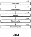
- Figure 3 illustrates a process for compressing image data using the entropy of the image.
- source image data is prepared for compression.
- the compression for each channel is performed separately.
- a channel may have one or more tiles that are processed separately.
- a transform is applied to the source image data at step 44.
- DCT or wavelet transforms may be used to transform image data (such as RGB, YUV, YCrCb, or other formats of image data) in preparation for compression.
- a dyadic wavelet transform is applied to each of the Y channel data, U channel data, and V channel data.
- a dyadic wavelet transform is applied to each of the G channel data, R and G channel difference data, and B and G channel difference data.
- the transformed data is then quantized at step 46.
- quantization may be skipped, or the quantization step size may be set to 1.0, resulting in no quantization.
- Different channels may have different quantization step sizes.
- different transform levels may have different quantization step sizes.
- the quantization step sizes may achieve a given level of "quality.”
- the quantization step sizes may achieve a fixed rate, perhaps through an iterative process.
- the quantized data is then entropy encoded at step 48, resulting in the compressed image data at step 50.
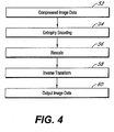
- Figure 4 illustrates a similar process for decompressing image data that was compressed using the entropy of the image.
- the compressed image data is provided to an entropy decoder at step 54.
- the decoded image data is rescaled in accordance with the quantization that was applied at step 46.
- An inverse transform is applied at step 58 to the rescaled image data, resulting in output image data at step 60 that corresponds to the image source data at step 42 from Figure 3 .
- the compression is lossless, the output image data will be the same as the input image data.
- the compression is lossy, the output image data may be different from the input image data. In some lossy compression embodiments, the differences between the reconstructed output image and the original input image may be visually unnoticeable.
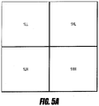
- Figures 5A-5C illustrate an example of applying a two-dimensional wavelet transform to decompose a tile into a series of levels which each contain a number of sub-bands. These subbands describe the high and low frequency components of the horizontal and vertical characteristics of the level.
- Figure 5A illustrates a quadrant 1LL that is composed of the low frequencies in the horizontal and vertical directions, a quadrant 1HL that is composed of the low frequencies in the horizontal direction and high frequencies in the vertical direction, a quadrant 1LH that is composed of the high frequencies in the horizontal direction and low frequencies in the vertical direction, and a quadrant 1HH that is composed of high frequencies in the horizontal and vertical directions.
- Each of the quadrants 1LL, 1HL, 1LH, and 1HH illustrated in Figure 5A have a resolution that is one-half of the original resolution in each direction. Thus, each quadrant has one-fourth the pixels of the original image.
- Figure 5B illustrates a further application of the wavelet transform to quadrant 1LL from Figure 5A , resulting in new quadrants 1LL, 1HL, 1LH, and 1HH, with each of the new quadrants having one-half of the resolution in each direction of quadrant 1LL from Figure 5A .
- Quadrant 2HL in Figure 5B corresponds to quadrant 1HL in Figure 5A
- quadrant 2LH in Figure 5B corresponds to quadrant 1LH in Figure 5A
- quadrant 2HH in Figure 5B corresponds to quadrant 1HH in Figure 5A .
- Figure 5C illustrates the process of further applying transforms to quadrant 1LL from Figure 5B .
- the process of applying transforms to the low-frequency quadrant 1LL can be continued, with each transformation resulting in progressively smaller resolution levels.
- the process may be repeated to provide, for example, up to five resolution levels.
- the process may be repeated to provide ten, twelve, or more resolution levels.
- the maximum number of possible resolution levels is only limited by the size of the original image, although less benefit may be gained when the resolution levels become too numerous.
- the transformed data can be stored in various ways.
- the transformed data could be stored by channel (e.g., red, blue, green 1 or green 2), by resolution (e.g., 1LL, 2LL, 3LL, etc.), by frames, or a combimtion of these approaches.
- Images captured at a high resolution may sometimes be viewed at a lower resolution.
- data from a video camera may be sent over a network connection to a viewing device having a lower resolution than the resolution of the captured data.
- image data is stored in a format that allows access to data at individual resolution levels, so that higher resolution information does not need to be processed in order to view lower resolution information.
- Some color filter arrays contain duplicate color elements. For example, a Bayer pattern typically contains two green elements for each red or blue element. Even though two green channels are captured, a single green channel could be used to reconstruct the images. Image data may be stored in a format that allows access to red, blue and the first green channel without requiring access to the second green channel. Thus, for some lower-bandwidth applications, only three of the four color channels may be used for reconstruction, and the fourth channel would not need to be transmitted.
- An array of offsets may be used to locate starting positions for various resolutions and/or channels.
- the offsets may identify locations directly. For example, offsets may point to specific locations as measured from the beginning of a file.
- the offsets may be cumulative of previous offsets.
- each frame of image data may have an associated offset.
- a frame of video data may comprise a plurality of tiles, where the tiles piece together to form the frame. Each tile may be associated with an offset. With the frames and/or tiles of video data, there may be additional offsets that are measured from the beginning of the frame or tile of video data and point to, for example, components relating to that frame of video data.
- the offsets may be bit-shifted so that the offsets indicate blocks of data.
- the file format may allow configuration of the number of bits to be shifted, which in turn may correspond to a maximum file size.
- the offset is bit-shifted 12 bits to provide a 4-Kbyte alignment
- an offset bit-shifted 14 bits provides a 16-Kbyte alignment
- a 32-bit offset allows a maximum offset indicator of 64 Terabytes.
- Offsets can be provided for specific resolutions and/or color channels, or offsets can be provided for groupings of resolutions and/or color channels.
- Example 1 illustrates offsets for each resolution level, with the green 1, blue and red channels grouped together and the green 2 channel grouped separately. The example assumes that there are M +1 resolution levels and N tiles. The first offset points to the first tile and the lowest resolution level for the green 1, blue and red channels. The second offset points to the next lowest resolution level, and the process continues up to the highest resolution level M +1. Similar offsets for the second tile follow the offsets for the first tile. The process continues for all N tiles. After the green 1, blue and red channels are processed for the M +1 resolution levels and the N tiles, the green 2 channel is processed for the M +1 resolution levels and the N tiles.
- Example 1 groups information (e.g., green 1 1LL, blue 1LL, red 1LL) to share the same offset.
- Each of the pieces of information could have its own offset. This would increase the total number of offsets, but it would also increase the flexibility in accessing certain pieces of information.
- Example 1 orders the information so that the green 1, blue, and red channels are ordered first for each of the tiles, followed by the green 2 channel for each of the tiles. Assuming that just the green 1, blue, and red channels are needed for processing, this ordering of needed data to be contiguous reduces the number of times a storage device will need to seek to a new location. In addition, there may be space between where the data ends for one offset and the beginning of the next offset. Grouping data together to reduce the number of offsets used may also mean that less space is wasted between offsets.
- Figure 6 illustrates an exemplary hierarchy for breaking down an image for compression.
- the elements shown in Figure 6 are not all necessary, and it is to be understood that elements may be removed from the hierarchy in some embodiments.
- a detected image may be separated into one or more channels, such as Y, U, and V channels; red, green and blue channels; or green, red-green difference, and blue-green difference channels.
- the channels may be divided into one or more tiles.
- the tiles may be transformed into one or more sub-bands.
- a wavelet transform may transform a tile into sub-bands as illustrated in Figure 5 .
- the sub-bands may be divided into precincts or packet partition locations.
- the precincts or packet partition locations in one sub-band have a spatial correlation with precincts or packet partition locations in other sub-bands, and the corresponding precincts or packet partition locations from the sub-bands are processed together.
- the precincts of packet partition locations may be divided into blocks.
- Each block may have a plurality of transformed and/or quantized values.
- the values in a block may be entropy coded as a group.
- the entropy coding may operate on a bit-level. For example, the most significant bits (MSB) for each value in the block may be entropy coded together. Similarly, the next MSB for each value may be entropy coded together.
- MSB most significant bits
- the entropy coding of bits may also take into consideration the evaluation of other bit-planes.
- One or more data components may be combined or used to provide various quality increments or resolution levels for a spatial location.
- data components are grouped into packets that provide one quality increment for one resolution level at a spatial location.
- a collection of packets that provide one quality increment at full resolution are combined into a layer.
- the layer for example, may correspond to a quality increment of a channel of an image at full resolution. Additional layers provide additional quality increments.
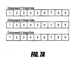
- Figure 7A illustrates an allocation of space for nine layers in the Y, U and V channels. As illustrated, each layer is allocated a fixed amount of space. This illustration corresponds to a rate-limited application of a compression algorithm.
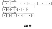
- Figure 7B also illustrates an allocation of space for nine layers in the Y, U and V channels.
- the space used by a layer is variable.
- the space used by a channel that compresses well is less than the space used by a channel that does not compress as well.
- the space used by the Y channel is greater than the space used by the U and V channels.
- Each layer within a channel may also use a variable amount of space. For example, layers 1 and 8 of the Y channel use more space than layers 4 and 6.
- the space used by the combination of layers in Figure 7B is greater than the space used by the combination of layers in Figure 7A .
- Some applications that use variable bit-rate encoding for the layers may have an overall bit-rate that is not to be exceeded.
- Each channel could be allocated a fixed amount of space, and layers that exceed the space limitations could be discarded.
- layers 7, 8 and 9 of the Y channel could be discarded so that the overall limitations for the Y channel are not exceeded.
- all the channels together could be allocated a fixed amount of space, and layers from one or more channels could be discarded as needed to meet the space limitations.
- layer 9 of the Y channel and layers 8 and 9 of the U and V channels could be discarded so that the overall space limitations for all of the channels are met.
- the resulting quality levels of each channel are substantially similar. For example, discarding layer 9 of the Y channel and layers 8 and 9 of the U and V channels means that the channels are within one quality level of each other. In some embodiments, layers are discarded in a way that ensures some channels have as good as or higher quality levels than other channels. For example, the Y channel may be more important for obtaining a reconstructed image that is visually lossless. As an example, none of the layers for the Y channel might be discarded, but layers 7, 8 and 9 in the U and V channels are discarded to comply with the overall space limitations.
- the difference in quality increments between channels may be more than one, but less than a set amount. For example, if the allowed difference in quality increments is 3, one channel might layers 1 through 8 while other channels might only use layers 1 through 5.
- Figures 7C and 7D are similar to Figures 7A and 7B , respectively, and show that the algorithms discussed above can apply to other color spaces. As shown in Figures 7C and 7D , the algorithms are applied to images having green channel data, red-green difference channel data, and blue-green difference channel data. Although Figures 7A-7D illustrate one channel for each color-space index, it is to be understood that multiple channels could be used. For example, the Y image data in Figures 7A-7B could be split into two or more channels. As another example, the green image data in Figures 7C-7D could be split into two or more channels.
- the compression is performed on image data from a sensor that has not been fully reconstructed.
- an image sensor may use a color filter array to detect selected wavelengths of light at a sensor element.
- the color filter array may comprise a repeating pattern 26, such as illustrated in Figure 8 .
- data from the sensor is compressed without converting some or all of the data to another color space.
- a sensor using a Bayer pattern color filter array may convert the red and blue data to red-green difference and blue-green difference data for compression, while the green data is compressed without conversion to another color space.
- a sensor using the color filter array may use a green channel (or a white channel), a white-green difference channel, red-green difference and blue-green difference data for compression.
- data from the sensor is compressed after conversion to another color space.
- a sensor using a Bayer pattern color filter array may convert the red, green and blue data to Y, U and V data.
- a difference value is obtained by obtaining a difference between two adjacent values.
- red-green or blue-green difference value may be obtained by determining the difference between a green value and an adjacent red value or blue value.
- an average value is used to obtain the difference value. For example, but without limitation, average values of 2, 3, 4, or more green image data values can be calculated and subtracted from red or blue picture elements in the vicinity of the green picture elements.
- some color filter arrays have twice as many green elements as red elements and blue elements.
- the red and blue elements each comprise 25% of the total color filter array
- the green elements comprise 50% of the total color filter array.
- additional green data image processing modules can be used.
- a first green data image processing module can process half of the green elements and a second green image data processing module can process the remaining green elements.
- embodiments can be used in conjunction with other types of patterns, such as for example, but without limitation, CMY and RGBW.
- a compression module 20 can be configured to perform any type of compression process.
- the compression module 20 performs a compression technique that benefits from the techniques performed by the compression preparation module 18.
- the compression preparation module 18 can be configured to determine green difference values for the red and blue data, thereby resulting in data that becomes more chroma-like.
- the compression technique performed by the compression module 20 can be of a type that benefits from the presence of chroma data to reduce the size of the compressed data output therefrom.
- the compression module 20 can be configured to compress the image data from the image processing module 20 to result in a visually lossless output.
- the compression module can be configured to apply any known compression technique, such as, but without limitation, H.264, MPEG4, Huffman, JPEG, JPEG 2000, MotionJPEG, DCT based codecs, wavelet based codecs, other codecs designed for compressing image data, or other techniques.
- the various parameters of the compression technique can be set to provide a visually lossless output.
- many of the compression techniques noted above can be adjusted to different compression rates, wherein when decompressed, the resulting image is better quality for lower compression rates and lower quality for higher compression rates.
- the compression module can be configured to compress the image data in a way that provides a visually lossless output, or can be configured to allow a user to adjust various parameters to obtain a visually lossless output.
- the term "visually lossless” is intended to include a reconstruction of processed image data that, when compared side by side with a reconstruction of original image data on the same display device, one of ordinary skill in the art would not be able to determine which image reconstruction is the original with a reasonable degree of accuracy, based only on a visual inspection of the images.
- the compressed data can be stored on a storage device.
- the storage device can be in the form of any type of digital storage, such as, for example, but without limitation, hard drives, solid-state drives, flash memory, optical discs, or any other type of memory device.
- the size of the storage device can be sufficiently large to store image data from the compression module 20 corresponding to at least about 30 minutes of video at 12 mega pixel resolution, 12-bit color resolution, and at 60 frames per second.
- the storage device can have any size.
- the storage device can be mounted on an exterior of a camera housing. Further, in some embodiments, the storage device can be connected to the other components through standard or custom communication ports, including, for example, but without limitation, Ethernet, USB, USB2, USB3, IEEE 1394 (including but not limited to FireWire 400, FireWire 800, FireWire S3200, FireWire S800T, i.LINK, DV), SATA and SCSI. Further, in some embodiments, the storage device can comprise a plurality of hard drives, such as those operating under a RAID protocol. However, any type of storage device can be used.
- the algorithms disclosed herein can be implemented as routines stored in a memory device. Additionally, a processor can be configured to execute the control routine. In some embodiments, custom circuitry may be used.
- the techniques can be applied to the processing of a single still image or multiple images. These processes can also be applied to the processing of continuous video, e.g., 10, 20, 24, 30, 60, and 120 frames per second, or any other frame rate.
- the image data from the image sensor 12 can be compressed by a compression ratio of 6 to 1 or greater and remain visually lossless.
- the image data has been transformed (e.g., by obtaining difference values)
- the raw image data is still available to an end user. For example, by reversing certain of the processes, all or substantially all of the original raw data can be extracted and thus further processed, filtered, and/or demosaiced using any process the user desires.
- the data stored in the storage device can be decompressed and demosaiced.
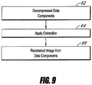
- Figure 9 illustrates an exemplary flowchart for reconstruction a compressed image.
- image data is decompressed.
- the image data may have been compressed according to channels.
- not all of the channels are decompressed for reconstruction of an image.
- a compressed image may have two channels that correspond to green picture elements. However, only one of the green channels may need to be decompressed to reconstruct an image. Decompressing only one channel allows for faster image reconstruction.
- not all of the quality levels are used for reconstruction of an image.
- the compressed channels may not have the same number of quality levels.
- a lower quality level for a channel may be chosen to, for example, allow for faster image reconstruction.
- the channels are decompressed so that each decompressed channel has approximately the same quality level.
- a gamma function or power log curve may be applied to the decompressed channels.
- the inverse of any of the pre-emphasis or gamma curves or other functions described above can be applied to the image data.
- the applied function may be an identity function, meaning that the output is the same as the input, or no correction function may be applied at all.
- the image is reconstructed from the decompressed data.
- one or more green channels are demosaiced, and the demosaiced green channels are then used to reconstruct other channels.
- a demosaiced green value can be used to reconstruct a red or blue value from a red-green or blue-green difference value that is at the same location as the demosaiced green value.
- the other channels can be demosaiced without requiring the green channel to be demosaiced first.
- a decompressed but not demosaiced green value can be used to reconstruct a red or blue value from a red-green or blue-green difference value that is located near the decompressed green value.
- an average of decompressed but not demosaiced green values can be used to reconstruct a red or blue value from a red-green or blue-green difference value that is located near the averaged decompressed green values.
- the average can provide the same value as used for compression, or it can be any other average of green values.
- the red and blue values are demosaiced with any appropriate algorithm.
- the demosaiced or reconstructed image data can be further processed.
- noise reduction techniques for example, but without limitation, noise reduction techniques, anti-aliasing techniques, or any other image processing technique can be applied to the image data.
Applications Claiming Priority (2)
| Application Number | Priority Date | Filing Date | Title |
|---|---|---|---|
| US28712009P | 2009-12-16 | 2009-12-16 | |
| PCT/US2010/060851 WO2011084639A2 (en) | 2009-12-16 | 2010-12-16 | Resolution based formatting of compressed image data |
Publications (3)
| Publication Number | Publication Date |
|---|---|
| EP2513861A2 EP2513861A2 (en) | 2012-10-24 |
| EP2513861A4 EP2513861A4 (en) | 2014-03-26 |
| EP2513861B1 true EP2513861B1 (en) | 2017-05-10 |
Family
ID=44151202
Family Applications (1)
| Application Number | Title | Priority Date | Filing Date |
|---|---|---|---|
| EP10842625.5A Active EP2513861B1 (en) | 2009-12-16 | 2010-12-16 | Resolution based formatting of compressed image data |
Country Status (6)
| Country | Link |
|---|---|
| US (3) | US8611652B2 (ja) |
| EP (1) | EP2513861B1 (ja) |
| JP (1) | JP5695080B2 (ja) |
| ES (1) | ES2628010T3 (ja) |
| TW (1) | TWI455571B (ja) |
| WO (1) | WO2011084639A2 (ja) |
Families Citing this family (22)
| Publication number | Priority date | Publication date | Assignee | Title |
|---|---|---|---|---|
| WO2011084639A2 (en) | 2009-12-16 | 2011-07-14 | Red. Com, Inc. | Resolution based formatting of compressed image data |
| JP5640370B2 (ja) * | 2009-12-18 | 2014-12-17 | ソニー株式会社 | 画像処理装置,画像処理方法及び撮像装置 |
| US9691339B2 (en) * | 2011-03-29 | 2017-06-27 | Renesas Electronics Corporation | Display apparatus and display apparatus control circuit |
| JP5474887B2 (ja) * | 2011-08-01 | 2014-04-16 | 株式会社ソニー・コンピュータエンタテインメント | 動画データ生成装置、動画像表示装置、動画データ生成方法、動画像表示方法、および動画像ファイルのデータ構造 |
| US20130166767A1 (en) * | 2011-11-23 | 2013-06-27 | General Electric Company | Systems and methods for rapid image delivery and monitoring |
| CN102695057B (zh) * | 2012-05-25 | 2014-11-19 | 西安空间无线电技术研究所 | 一种用于图像数据的压缩系统 |
| JP5749401B2 (ja) * | 2012-06-11 | 2015-07-15 | 富士フイルム株式会社 | 画像処理装置、撮像装置、コンピュータ、画像処理方法及びプログラム |
| US20140294314A1 (en) * | 2013-04-02 | 2014-10-02 | Samsung Display Co., Ltd. | Hierarchical image and video codec |
| CN104125461B (zh) * | 2013-04-27 | 2017-06-23 | 深圳市振华微电子有限公司 | 一种大尺寸的图像压缩处理系统及方法 |
| US9549161B2 (en) * | 2013-07-08 | 2017-01-17 | Samsung Display Co., Ltd. | Image and video in mosaic formats |
| US10045029B2 (en) * | 2014-05-06 | 2018-08-07 | Intel Corporation | Clustering and encoding for color compression |
| GB2532063A (en) * | 2014-11-07 | 2016-05-11 | Sony Corp | A method, server, client and software |
| US9734597B2 (en) * | 2015-12-18 | 2017-08-15 | Intel Corporation | Interpolated minimum-maximum compression/decompression for efficient processing of graphics data at computing devices |
| JP2017143355A (ja) * | 2016-02-08 | 2017-08-17 | キヤノン株式会社 | 画像符号化装置及び方法及び撮像装置 |
| WO2018037525A1 (ja) * | 2016-08-25 | 2018-03-01 | Necディスプレイソリューションズ株式会社 | 自己画像診断方法、自己画像診断プログラム、ディスプレイ装置、及び自己画像診断システム |
| US11019336B2 (en) * | 2017-07-05 | 2021-05-25 | Red.Com, Llc | Video image data processing in electronic devices |
| JP7065594B2 (ja) * | 2017-12-08 | 2022-05-12 | キヤノン株式会社 | 画像符号化装置及びその制御方法、並びにプログラム |
| GB2583061B (en) * | 2019-02-12 | 2023-03-15 | Advanced Risc Mach Ltd | Data processing systems |
| US20210398322A1 (en) * | 2020-06-17 | 2021-12-23 | Palantir Technologies Inc. | Approaches for compressing and distributing image data |
| US11647193B2 (en) | 2020-12-18 | 2023-05-09 | Meta Platforms Technologies, Llc | Adaptive range packing compression |
| US11270468B1 (en) * | 2020-12-18 | 2022-03-08 | Facebook Technologies, Llc. | Joint color image and texture data compression |
| US20220417537A1 (en) * | 2021-06-23 | 2022-12-29 | Black Sesame International Holding Limited | Unprocessed image coding and decoding |
Family Cites Families (41)
| Publication number | Priority date | Publication date | Assignee | Title |
|---|---|---|---|---|
| US6549666B1 (en) | 1994-09-21 | 2003-04-15 | Ricoh Company, Ltd | Reversible embedded wavelet system implementation |
| US5875122A (en) | 1996-12-17 | 1999-02-23 | Intel Corporation | Integrated systolic architecture for decomposition and reconstruction of signals using wavelet transforms |
| US6272180B1 (en) * | 1997-11-21 | 2001-08-07 | Sharp Laboratories Of America, Inc. | Compression and decompression of reference frames in a video decoder |
| US6154493A (en) | 1998-05-21 | 2000-11-28 | Intel Corporation | Compression of color images based on a 2-dimensional discrete wavelet transform yielding a perceptually lossless image |
| US6124811A (en) | 1998-07-02 | 2000-09-26 | Intel Corporation | Real time algorithms and architectures for coding images compressed by DWT-based techniques |
| US6778709B1 (en) * | 1999-03-12 | 2004-08-17 | Hewlett-Packard Development Company, L.P. | Embedded block coding with optimized truncation |
| FR2792432B1 (fr) | 1999-04-15 | 2001-07-13 | Canon Kk | Dispositif et procede de transformation de signal numerique |
| US7372485B1 (en) * | 1999-06-08 | 2008-05-13 | Lightsurf Technologies, Inc. | Digital camera device and methodology for distributed processing and wireless transmission of digital images |
| US6798901B1 (en) | 1999-10-01 | 2004-09-28 | Intel Corporation | Method of compressing a color image |
| JP2001290820A (ja) * | 2000-01-31 | 2001-10-19 | Mitsubishi Electric Corp | 映像収集装置、映像検索装置および映像収集検索システム |
| US6549674B1 (en) | 2000-10-12 | 2003-04-15 | Picsurf, Inc. | Image compression based on tiled wavelet-like transform using edge and non-edge filters |
| US6785423B1 (en) * | 2000-05-26 | 2004-08-31 | Eastman Kodak Company | Producing a compressed digital image organized into layers having information relating to different viewing conditions and resolutions |
| TW594627B (en) * | 2001-05-09 | 2004-06-21 | Clairvoyante Lab Inc | Conversion of a sub-pixel format data to another sub-pixel data format |
| FR2826823B1 (fr) * | 2001-06-27 | 2003-10-10 | Canon Kk | Procede et dispositif de traitement d'un signal numerique code |
| US20030112863A1 (en) * | 2001-07-12 | 2003-06-19 | Demos Gary A. | Method and system for improving compressed image chroma information |
| JP4267848B2 (ja) | 2001-09-25 | 2009-05-27 | 株式会社リコー | 画像符号化装置、画像復号装置、画像符号化方法、及び、画像復号方法 |
| JP2003125331A (ja) * | 2001-10-17 | 2003-04-25 | Fuji Photo Film Co Ltd | 画像記録方法及び装置、並びに画像再生方法及び装置 |
| US7403564B2 (en) * | 2001-11-21 | 2008-07-22 | Vixs Systems, Inc. | System and method for multiple channel video transcoding |
| JP3922919B2 (ja) * | 2001-12-11 | 2007-05-30 | 株式会社リコー | 静止画像伸長装置及び静止画像伸長方法 |
| US6956976B2 (en) | 2002-01-04 | 2005-10-18 | Warner Bros. Enterianment Inc. | Reduction of differential resolution of separations |
| US7330596B2 (en) | 2002-07-17 | 2008-02-12 | Ricoh Company, Ltd. | Image decoding technique for suppressing tile boundary distortion |
| JP4262017B2 (ja) * | 2002-09-26 | 2009-05-13 | キヤノン株式会社 | 画像生成装置及びその方法 |
| JP3928859B2 (ja) * | 2002-11-11 | 2007-06-13 | 株式会社リコー | 画像処理装置、画像処理方法、プログラム及び記録媒体 |
| KR100939711B1 (ko) * | 2002-12-12 | 2010-02-01 | 엘지전자 주식회사 | 텍스트 기반의 서브타이틀 재생장치 및 방법 |
| JP2004221836A (ja) | 2003-01-14 | 2004-08-05 | Ricoh Co Ltd | 画像処理装置、プログラム、記憶媒体及び符号伸長方法 |
| JP2004248152A (ja) * | 2003-02-17 | 2004-09-02 | Ricoh Co Ltd | 画像圧縮装置、画像伸張装置、画像圧縮方法、画像伸張方法、プログラム、及び記録媒体 |
| US7460131B2 (en) * | 2003-09-30 | 2008-12-02 | Sharp Laboratories Of America, Inc. | Methods and systems for processing image data for display on LC displays |
| US6989773B2 (en) * | 2004-02-13 | 2006-01-24 | Hewlett-Packard Development Company, L.P. | Media data encoding device |
| US7504968B2 (en) * | 2004-02-13 | 2009-03-17 | Hewlett-Packard Development Company, L.P. | Media data decoding device |
| US8832434B2 (en) * | 2004-02-13 | 2014-09-09 | Hewlett-Packard Development Company, L.P. | Methods for generating data for describing scalable media |
| KR100689430B1 (ko) * | 2004-12-16 | 2007-03-08 | 삼성전자주식회사 | 디지털 홈 서비스에서 하이브리드 모니터링을 통한 동적서비스 품질 매핑 장치 및 방법 |
| TWI259725B (en) * | 2005-04-28 | 2006-08-01 | Benq Corp | Methods and systems for transmitting AV information |
| JP4716949B2 (ja) | 2005-09-02 | 2011-07-06 | 株式会社リコー | 画像処理装置および画像処理方法 |
| JP4688165B2 (ja) * | 2005-09-30 | 2011-05-25 | 株式会社リコー | 画像処理装置及び画像処理方法 |
| US7796836B2 (en) | 2006-03-03 | 2010-09-14 | General Atomics | Color condensation for image transformation and/or compression |
| US8014597B1 (en) * | 2006-03-22 | 2011-09-06 | Woodman Labs | Method for efficient compression and decoding of single sensor color image data |
| US8237830B2 (en) | 2007-04-11 | 2012-08-07 | Red.Com, Inc. | Video camera |
| EP2793219A1 (en) | 2007-04-11 | 2014-10-22 | Red.Com, Inc. | Video camera |
| US8149319B2 (en) | 2007-12-03 | 2012-04-03 | Ricoh Co., Ltd. | End-to-end design of electro-optic imaging systems for color-correlated objects |
| JP5158096B2 (ja) * | 2008-01-08 | 2013-03-06 | 日本電気株式会社 | 符号化用データ生成装置、符号化用データ生成方法、復号装置および復号方法 |
| WO2011084639A2 (en) | 2009-12-16 | 2011-07-14 | Red. Com, Inc. | Resolution based formatting of compressed image data |
-
2010
- 2010-12-16 WO PCT/US2010/060851 patent/WO2011084639A2/en active Application Filing
- 2010-12-16 US US12/970,653 patent/US8611652B2/en active Active
- 2010-12-16 ES ES10842625.5T patent/ES2628010T3/es active Active
- 2010-12-16 JP JP2012544852A patent/JP5695080B2/ja active Active
- 2010-12-16 EP EP10842625.5A patent/EP2513861B1/en active Active
- 2010-12-16 TW TW099144282A patent/TWI455571B/zh not_active IP Right Cessation
-
2013
- 2013-11-15 US US14/081,297 patent/US9479749B2/en active Active
-
2016
- 2016-09-13 US US15/264,454 patent/US9906764B2/en active Active
Also Published As
| Publication number | Publication date |
|---|---|
| US9479749B2 (en) | 2016-10-25 |
| US20110150330A1 (en) | 2011-06-23 |
| US9906764B2 (en) | 2018-02-27 |
| ES2628010T3 (es) | 2017-08-01 |
| JP2013515395A (ja) | 2013-05-02 |
| TWI455571B (zh) | 2014-10-01 |
| EP2513861A4 (en) | 2014-03-26 |
| US20140176734A1 (en) | 2014-06-26 |
| US20170099475A1 (en) | 2017-04-06 |
| US8611652B2 (en) | 2013-12-17 |
| WO2011084639A2 (en) | 2011-07-14 |
| TW201143353A (en) | 2011-12-01 |
| JP5695080B2 (ja) | 2015-04-01 |
| WO2011084639A3 (en) | 2011-10-13 |
| EP2513861A2 (en) | 2012-10-24 |
Similar Documents
| Publication | Publication Date | Title |
|---|---|---|
| US9906764B2 (en) | Resolution based formatting of compressed image data | |
| US9596385B2 (en) | Electronic apparatus | |
| US7656561B2 (en) | Image compression for rapid high-quality imaging | |
| US9516197B2 (en) | Apparatus and method for lossless compression of raw color sensor data from a color array filtered image sensor | |
| Chao et al. | Pre-demosaic light field image compression using graph lifting transform | |
| EP1769459B1 (en) | Image compression for rapid high-quality imaging | |
| Perra et al. | Light field compression on sliced lenslet array | |
| CN108156461A (zh) | 一种Bayer图像压缩方法及装置 | |
| AU2016213747B2 (en) | Video camera | |
| Bazhyna | Image compression in digital cameras | |
| AU2012216606A1 (en) | Video camera |
Legal Events
| Date | Code | Title | Description |
|---|---|---|---|
| PUAI | Public reference made under article 153(3) epc to a published international application that has entered the european phase |
Free format text: ORIGINAL CODE: 0009012 |
|
| 17P | Request for examination filed |
Effective date: 20120705 |
|
| AK | Designated contracting states |
Kind code of ref document: A2 Designated state(s): AL AT BE BG CH CY CZ DE DK EE ES FI FR GB GR HR HU IE IS IT LI LT LU LV MC MK MT NL NO PL PT RO RS SE SI SK SM TR |
|
| DAX | Request for extension of the european patent (deleted) | ||
| A4 | Supplementary search report drawn up and despatched |
Effective date: 20140225 |
|
| RIC1 | Information provided on ipc code assigned before grant |
Ipc: G06T 3/00 20060101AFI20140217BHEP Ipc: H04N 3/14 20060101ALI20140217BHEP Ipc: H04N 19/30 20140101ALI20140217BHEP Ipc: G06T 1/60 20060101ALI20140217BHEP Ipc: G06T 3/40 20060101ALI20140217BHEP Ipc: G06T 5/00 20060101ALI20140217BHEP Ipc: H04N 5/30 20060101ALI20140217BHEP Ipc: H04N 19/423 20140101ALI20140217BHEP Ipc: H04N 19/46 20140101ALI20140217BHEP Ipc: G06T 1/00 20060101ALI20140217BHEP Ipc: H04N 19/63 20140101ALI20140217BHEP Ipc: H04N 9/07 20060101ALI20140217BHEP |
|
| RAP1 | Party data changed (applicant data changed or rights of an application transferred) |
Owner name: RED.COM, INC. |
|
| 17Q | First examination report despatched |
Effective date: 20150710 |
|
| REG | Reference to a national code |
Ref country code: DE Ref legal event code: R079 Ref document number: 602010042329 Country of ref document: DE Free format text: PREVIOUS MAIN CLASS: G06T0003000000 Ipc: H04N0019300000 |
|
| GRAP | Despatch of communication of intention to grant a patent |
Free format text: ORIGINAL CODE: EPIDOSNIGR1 |
|
| STAA | Information on the status of an ep patent application or granted ep patent |
Free format text: STATUS: GRANT OF PATENT IS INTENDED |
|
| RIC1 | Information provided on ipc code assigned before grant |
Ipc: H04N 19/423 20140101ALI20161124BHEP Ipc: H04N 9/64 20060101ALI20161124BHEP Ipc: H04N 19/30 20140101AFI20161124BHEP |
|
| INTG | Intention to grant announced |
Effective date: 20161215 |
|
| RIN1 | Information on inventor provided before grant (corrected) |
Inventor name: JANNARD, JAMES H. Inventor name: LOHMAN, ROB WOUTER Inventor name: GREENE, RICHARD |
|
| GRAS | Grant fee paid |
Free format text: ORIGINAL CODE: EPIDOSNIGR3 |
|
| GRAA | (expected) grant |
Free format text: ORIGINAL CODE: 0009210 |
|
| STAA | Information on the status of an ep patent application or granted ep patent |
Free format text: STATUS: THE PATENT HAS BEEN GRANTED |
|
| AK | Designated contracting states |
Kind code of ref document: B1 Designated state(s): AL AT BE BG CH CY CZ DE DK EE ES FI FR GB GR HR HU IE IS IT LI LT LU LV MC MK MT NL NO PL PT RO RS SE SI SK SM TR |
|
| REG | Reference to a national code |
Ref country code: GB Ref legal event code: FG4D |
|
| REG | Reference to a national code |
Ref country code: AT Ref legal event code: REF Ref document number: 893446 Country of ref document: AT Kind code of ref document: T Effective date: 20170515 Ref country code: CH Ref legal event code: EP |
|
| REG | Reference to a national code |
Ref country code: IE Ref legal event code: FG4D |
|
| REG | Reference to a national code |
Ref country code: DE Ref legal event code: R096 Ref document number: 602010042329 Country of ref document: DE |
|
| REG | Reference to a national code |
Ref country code: ES Ref legal event code: FG2A Ref document number: 2628010 Country of ref document: ES Kind code of ref document: T3 Effective date: 20170801 |
|
| REG | Reference to a national code |
Ref country code: NL Ref legal event code: FP |
|
| REG | Reference to a national code |
Ref country code: SE Ref legal event code: TRGR |
|
| RAP2 | Party data changed (patent owner data changed or rights of a patent transferred) |
Owner name: RED.COM, LLC |
|
| REG | Reference to a national code |
Ref country code: NO Ref legal event code: T2 Effective date: 20170510 Ref country code: LT Ref legal event code: MG4D |
|
| REG | Reference to a national code |
Ref country code: AT Ref legal event code: MK05 Ref document number: 893446 Country of ref document: AT Kind code of ref document: T Effective date: 20170510 |
|
| REG | Reference to a national code |
Ref country code: NL Ref legal event code: PD Owner name: RED.COM, LLC; US Free format text: DETAILS ASSIGNMENT: CHANGE OF OWNER(S), CHANGE OF LEGAL ENTITY; FORMER OWNER NAME: RED.COM, INC. Effective date: 20170817 |
|
| PG25 | Lapsed in a contracting state [announced via postgrant information from national office to epo] |
Ref country code: HR Free format text: LAPSE BECAUSE OF FAILURE TO SUBMIT A TRANSLATION OF THE DESCRIPTION OR TO PAY THE FEE WITHIN THE PRESCRIBED TIME-LIMIT Effective date: 20170510 Ref country code: LT Free format text: LAPSE BECAUSE OF FAILURE TO SUBMIT A TRANSLATION OF THE DESCRIPTION OR TO PAY THE FEE WITHIN THE PRESCRIBED TIME-LIMIT Effective date: 20170510 Ref country code: AT Free format text: LAPSE BECAUSE OF FAILURE TO SUBMIT A TRANSLATION OF THE DESCRIPTION OR TO PAY THE FEE WITHIN THE PRESCRIBED TIME-LIMIT Effective date: 20170510 Ref country code: GR Free format text: LAPSE BECAUSE OF FAILURE TO SUBMIT A TRANSLATION OF THE DESCRIPTION OR TO PAY THE FEE WITHIN THE PRESCRIBED TIME-LIMIT Effective date: 20170811 |
|
| REG | Reference to a national code |
Ref country code: FR Ref legal event code: PLFP Year of fee payment: 8 |
|
| PG25 | Lapsed in a contracting state [announced via postgrant information from national office to epo] |
Ref country code: BG Free format text: LAPSE BECAUSE OF FAILURE TO SUBMIT A TRANSLATION OF THE DESCRIPTION OR TO PAY THE FEE WITHIN THE PRESCRIBED TIME-LIMIT Effective date: 20170810 Ref country code: RS Free format text: LAPSE BECAUSE OF FAILURE TO SUBMIT A TRANSLATION OF THE DESCRIPTION OR TO PAY THE FEE WITHIN THE PRESCRIBED TIME-LIMIT Effective date: 20170510 Ref country code: IS Free format text: LAPSE BECAUSE OF FAILURE TO SUBMIT A TRANSLATION OF THE DESCRIPTION OR TO PAY THE FEE WITHIN THE PRESCRIBED TIME-LIMIT Effective date: 20170910 Ref country code: LV Free format text: LAPSE BECAUSE OF FAILURE TO SUBMIT A TRANSLATION OF THE DESCRIPTION OR TO PAY THE FEE WITHIN THE PRESCRIBED TIME-LIMIT Effective date: 20170510 Ref country code: PL Free format text: LAPSE BECAUSE OF FAILURE TO SUBMIT A TRANSLATION OF THE DESCRIPTION OR TO PAY THE FEE WITHIN THE PRESCRIBED TIME-LIMIT Effective date: 20170510 |
|
| PG25 | Lapsed in a contracting state [announced via postgrant information from national office to epo] |
Ref country code: DK Free format text: LAPSE BECAUSE OF FAILURE TO SUBMIT A TRANSLATION OF THE DESCRIPTION OR TO PAY THE FEE WITHIN THE PRESCRIBED TIME-LIMIT Effective date: 20170510 Ref country code: CZ Free format text: LAPSE BECAUSE OF FAILURE TO SUBMIT A TRANSLATION OF THE DESCRIPTION OR TO PAY THE FEE WITHIN THE PRESCRIBED TIME-LIMIT Effective date: 20170510 Ref country code: SK Free format text: LAPSE BECAUSE OF FAILURE TO SUBMIT A TRANSLATION OF THE DESCRIPTION OR TO PAY THE FEE WITHIN THE PRESCRIBED TIME-LIMIT Effective date: 20170510 Ref country code: RO Free format text: LAPSE BECAUSE OF FAILURE TO SUBMIT A TRANSLATION OF THE DESCRIPTION OR TO PAY THE FEE WITHIN THE PRESCRIBED TIME-LIMIT Effective date: 20170510 Ref country code: EE Free format text: LAPSE BECAUSE OF FAILURE TO SUBMIT A TRANSLATION OF THE DESCRIPTION OR TO PAY THE FEE WITHIN THE PRESCRIBED TIME-LIMIT Effective date: 20170510 |
|
| REG | Reference to a national code |
Ref country code: DE Ref legal event code: R097 Ref document number: 602010042329 Country of ref document: DE |
|
| PG25 | Lapsed in a contracting state [announced via postgrant information from national office to epo] |
Ref country code: SM Free format text: LAPSE BECAUSE OF FAILURE TO SUBMIT A TRANSLATION OF THE DESCRIPTION OR TO PAY THE FEE WITHIN THE PRESCRIBED TIME-LIMIT Effective date: 20170510 |
|
| PLBE | No opposition filed within time limit |
Free format text: ORIGINAL CODE: 0009261 |
|
| STAA | Information on the status of an ep patent application or granted ep patent |
Free format text: STATUS: NO OPPOSITION FILED WITHIN TIME LIMIT |
|
| 26N | No opposition filed |
Effective date: 20180213 |
|
| PG25 | Lapsed in a contracting state [announced via postgrant information from national office to epo] |
Ref country code: SI Free format text: LAPSE BECAUSE OF FAILURE TO SUBMIT A TRANSLATION OF THE DESCRIPTION OR TO PAY THE FEE WITHIN THE PRESCRIBED TIME-LIMIT Effective date: 20170510 |
|
| REG | Reference to a national code |
Ref country code: CH Ref legal event code: PL |
|
| REG | Reference to a national code |
Ref country code: IE Ref legal event code: MM4A |
|
| PG25 | Lapsed in a contracting state [announced via postgrant information from national office to epo] |
Ref country code: LU Free format text: LAPSE BECAUSE OF NON-PAYMENT OF DUE FEES Effective date: 20171216 Ref country code: MT Free format text: LAPSE BECAUSE OF NON-PAYMENT OF DUE FEES Effective date: 20171216 |
|
| REG | Reference to a national code |
Ref country code: BE Ref legal event code: MM Effective date: 20171231 |
|
| PG25 | Lapsed in a contracting state [announced via postgrant information from national office to epo] |
Ref country code: IE Free format text: LAPSE BECAUSE OF NON-PAYMENT OF DUE FEES Effective date: 20171216 |
|
| PG25 | Lapsed in a contracting state [announced via postgrant information from national office to epo] |
Ref country code: CH Free format text: LAPSE BECAUSE OF NON-PAYMENT OF DUE FEES Effective date: 20171231 Ref country code: LI Free format text: LAPSE BECAUSE OF NON-PAYMENT OF DUE FEES Effective date: 20171231 Ref country code: BE Free format text: LAPSE BECAUSE OF NON-PAYMENT OF DUE FEES Effective date: 20171231 |
|
| REG | Reference to a national code |
Ref country code: DE Ref legal event code: R082 Ref document number: 602010042329 Country of ref document: DE Representative=s name: PAGE, WHITE & FARRER GERMANY LLP, DE |
|
| PG25 | Lapsed in a contracting state [announced via postgrant information from national office to epo] |
Ref country code: HU Free format text: LAPSE BECAUSE OF FAILURE TO SUBMIT A TRANSLATION OF THE DESCRIPTION OR TO PAY THE FEE WITHIN THE PRESCRIBED TIME-LIMIT; INVALID AB INITIO Effective date: 20101216 Ref country code: MC Free format text: LAPSE BECAUSE OF FAILURE TO SUBMIT A TRANSLATION OF THE DESCRIPTION OR TO PAY THE FEE WITHIN THE PRESCRIBED TIME-LIMIT Effective date: 20170510 |
|
| PG25 | Lapsed in a contracting state [announced via postgrant information from national office to epo] |
Ref country code: CY Free format text: LAPSE BECAUSE OF NON-PAYMENT OF DUE FEES Effective date: 20170510 |
|
| PG25 | Lapsed in a contracting state [announced via postgrant information from national office to epo] |
Ref country code: MK Free format text: LAPSE BECAUSE OF FAILURE TO SUBMIT A TRANSLATION OF THE DESCRIPTION OR TO PAY THE FEE WITHIN THE PRESCRIBED TIME-LIMIT Effective date: 20170510 |
|
| PGFP | Annual fee paid to national office [announced via postgrant information from national office to epo] |
Ref country code: FI Payment date: 20191209 Year of fee payment: 10 Ref country code: NO Payment date: 20191210 Year of fee payment: 10 Ref country code: NL Payment date: 20191212 Year of fee payment: 10 Ref country code: SE Payment date: 20191210 Year of fee payment: 10 |
|
| PGFP | Annual fee paid to national office [announced via postgrant information from national office to epo] |
Ref country code: IT Payment date: 20191209 Year of fee payment: 10 Ref country code: FR Payment date: 20191115 Year of fee payment: 10 |
|
| PG25 | Lapsed in a contracting state [announced via postgrant information from national office to epo] |
Ref country code: TR Free format text: LAPSE BECAUSE OF FAILURE TO SUBMIT A TRANSLATION OF THE DESCRIPTION OR TO PAY THE FEE WITHIN THE PRESCRIBED TIME-LIMIT Effective date: 20170510 |
|
| PGFP | Annual fee paid to national office [announced via postgrant information from national office to epo] |
Ref country code: ES Payment date: 20200102 Year of fee payment: 10 |
|
| PG25 | Lapsed in a contracting state [announced via postgrant information from national office to epo] |
Ref country code: PT Free format text: LAPSE BECAUSE OF FAILURE TO SUBMIT A TRANSLATION OF THE DESCRIPTION OR TO PAY THE FEE WITHIN THE PRESCRIBED TIME-LIMIT Effective date: 20170510 |
|
| PG25 | Lapsed in a contracting state [announced via postgrant information from national office to epo] |
Ref country code: AL Free format text: LAPSE BECAUSE OF FAILURE TO SUBMIT A TRANSLATION OF THE DESCRIPTION OR TO PAY THE FEE WITHIN THE PRESCRIBED TIME-LIMIT Effective date: 20170510 |
|
| REG | Reference to a national code |
Ref country code: FI Ref legal event code: MAE |
|
| REG | Reference to a national code |
Ref country code: NO Ref legal event code: MMEP |
|
| PG25 | Lapsed in a contracting state [announced via postgrant information from national office to epo] |
Ref country code: FI Free format text: LAPSE BECAUSE OF NON-PAYMENT OF DUE FEES Effective date: 20201216 |
|
| REG | Reference to a national code |
Ref country code: SE Ref legal event code: EUG |
|
| REG | Reference to a national code |
Ref country code: NL Ref legal event code: MM Effective date: 20210101 |
|
| PG25 | Lapsed in a contracting state [announced via postgrant information from national office to epo] |
Ref country code: NL Free format text: LAPSE BECAUSE OF NON-PAYMENT OF DUE FEES Effective date: 20210101 |
|
| PG25 | Lapsed in a contracting state [announced via postgrant information from national office to epo] |
Ref country code: FR Free format text: LAPSE BECAUSE OF NON-PAYMENT OF DUE FEES Effective date: 20201231 Ref country code: IT Free format text: LAPSE BECAUSE OF NON-PAYMENT OF DUE FEES Effective date: 20201216 |
|
| PG25 | Lapsed in a contracting state [announced via postgrant information from national office to epo] |
Ref country code: SE Free format text: LAPSE BECAUSE OF NON-PAYMENT OF DUE FEES Effective date: 20201217 Ref country code: NO Free format text: LAPSE BECAUSE OF NON-PAYMENT OF DUE FEES Effective date: 20201231 |
|
| REG | Reference to a national code |
Ref country code: ES Ref legal event code: FD2A Effective date: 20220412 |
|
| PG25 | Lapsed in a contracting state [announced via postgrant information from national office to epo] |
Ref country code: ES Free format text: LAPSE BECAUSE OF NON-PAYMENT OF DUE FEES Effective date: 20201217 |
|
| PGFP | Annual fee paid to national office [announced via postgrant information from national office to epo] |
Ref country code: GB Payment date: 20221027 Year of fee payment: 13 Ref country code: DE Payment date: 20220622 Year of fee payment: 13 |