EP2513530B1 - Gleitringdichtung - Google Patents
Gleitringdichtung Download PDFInfo
- Publication number
- EP2513530B1 EP2513530B1 EP10808968.1A EP10808968A EP2513530B1 EP 2513530 B1 EP2513530 B1 EP 2513530B1 EP 10808968 A EP10808968 A EP 10808968A EP 2513530 B1 EP2513530 B1 EP 2513530B1
- Authority
- EP
- European Patent Office
- Prior art keywords
- sliding
- slide ring
- ring
- sliding surface
- ring seal
- Prior art date
- Legal status (The legal status is an assumption and is not a legal conclusion. Google has not performed a legal analysis and makes no representation as to the accuracy of the status listed.)
- Active
Links
- 238000000576 coating method Methods 0.000 claims description 7
- 239000011248 coating agent Substances 0.000 claims description 6
- VYZAMTAEIAYCRO-UHFFFAOYSA-N Chromium Chemical compound [Cr] VYZAMTAEIAYCRO-UHFFFAOYSA-N 0.000 claims description 3
- 238000007517 polishing process Methods 0.000 claims description 2
- 230000013011 mating Effects 0.000 description 9
- 238000007789 sealing Methods 0.000 description 8
- 230000002093 peripheral effect Effects 0.000 description 5
- 239000007769 metal material Substances 0.000 description 2
- 229910000831 Steel Inorganic materials 0.000 description 1
- 229910001347 Stellite Inorganic materials 0.000 description 1
- 229910052804 chromium Inorganic materials 0.000 description 1
- 239000011651 chromium Substances 0.000 description 1
- AHICWQREWHDHHF-UHFFFAOYSA-N chromium;cobalt;iron;manganese;methane;molybdenum;nickel;silicon;tungsten Chemical compound C.[Si].[Cr].[Mn].[Fe].[Co].[Ni].[Mo].[W] AHICWQREWHDHHF-UHFFFAOYSA-N 0.000 description 1
- 239000002131 composite material Substances 0.000 description 1
- 230000001419 dependent effect Effects 0.000 description 1
- 238000011161 development Methods 0.000 description 1
- 230000018109 developmental process Effects 0.000 description 1
- 238000010586 diagram Methods 0.000 description 1
- 230000000694 effects Effects 0.000 description 1
- 230000000977 initiatory effect Effects 0.000 description 1
- 239000000843 powder Substances 0.000 description 1
- 238000005096 rolling process Methods 0.000 description 1
- 238000000926 separation method Methods 0.000 description 1
- 230000003068 static effect Effects 0.000 description 1
- 239000010959 steel Substances 0.000 description 1
Images

Classifications
-
- F—MECHANICAL ENGINEERING; LIGHTING; HEATING; WEAPONS; BLASTING
- F16—ENGINEERING ELEMENTS AND UNITS; GENERAL MEASURES FOR PRODUCING AND MAINTAINING EFFECTIVE FUNCTIONING OF MACHINES OR INSTALLATIONS; THERMAL INSULATION IN GENERAL
- F16J—PISTONS; CYLINDERS; SEALINGS
- F16J15/00—Sealings
- F16J15/16—Sealings between relatively-moving surfaces
- F16J15/34—Sealings between relatively-moving surfaces with slip-ring pressed against a more or less radial face on one member
- F16J15/3436—Pressing means
- F16J15/344—Pressing means the pressing force being applied by means of an elastic ring supporting the slip-ring
Definitions
- the invention relates to a mechanical seal according to the generic part of the first claim.
- the DE 101 55 653 C2 discloses a mechanical seal, in particular a drive seal, comprising an angular sliding and mating ring, which form a sealing surface with their radial sealing legs and consisting of elastomeric sealing bodies between the mechanical seal receiving housing and the radially outer surface of the axial limbs of the sliding and Counter ring are arranged.
- a mechanical seal in particular a drive seal, comprising a counter and a sliding ring, each having a clamping surface for receiving an elastomeric spring body, a housing associated with the counter and sliding ring with a counter-clamping surface for the spring body, the housing lying one inside the other are connected and an anti-rotation is provided in the region of the counter and the sliding ring.
- EP 0 779 457 A1 is a generic mechanical seal has become known, consisting of a sliding and / or mating ring of metallic material with a specific for receiving an elastic rolling body conical peripheral surface.
- the medium facing surface of the sliding and / or counter ring is coated with a baked powder coating.
- a secondary sealing point is provided on the medium side in the region of the sliding and / or counter ring, which can be formed from an O-ring and possibly a support ring.
- the sealing surface of one of the rings is slightly convex shaped by a lapping operation to thereby provide the necessary wedge-shaped space at the outer radial portions of the sealing ring, thereby initiating and maintaining the separation of the surfaces during operation.
- the US 5,544,896 relates to a mechanical seal in which the sealing surfaces of the sliding and counter-ring over the entire surface lie on each other and at least one of the sealing rings is formed of a composite material.
- the invention has for its object to extend the technical application of mechanical seals, especially drive seals, to the effect that selbige for peripheral speeds above 10 m / s, in particular for peripheral speeds up to 30 m / s, can be used and capable of today common Radial shaft seals to replace significantly shorter life.
- the sliding ring has a, running at an angle to the radially extending sliding surface, the trapezoidal surface and the convex contour is provided in the trapezoidal region of the sliding surface.
- the mechanical seal only contains a sliding ring in operative connection with an elastomeric spring element, in which the sliding surface is provided with the contour according to the invention.
- the mechanical seal according to the invention can be used in use as a drive seal for significantly higher peripheral speeds up to 30 m / s and for this reason able to replace radial shaft seals with significantly shorter life.
- the respective contour is preferably generated by a polishing process or a turning operation of the sliding surface.
- the sliding surface may be useful to provide the sliding surface with a low-friction coating.
- coatings DLC, PVD or chrome layers are suitable.
- the person skilled in the art will select the suitable type of coating.
- the sliding ring is approximately angular in cross-section and has a radially extending sliding surface and a, at an angle thereto extending trapezoidal surface, wherein the sliding surface is provided with the convex contour, in the trapezoidal region of the uniform surface.
- a drive seal consists in many cases of a sliding and a mating ring, wherein the sliding surfaces face each other.
- both the sliding surface of the sliding and the counter-ring is provided with the convex contour, wherein it is particularly advantageous that the sliding surface contours are formed substantially the same.
- the local surface pressure is significantly reduced and, moreover, there are also advantages with possible misalignment problems between the sliding surface of the sliding ring and the mating surface, in particular the mating surface of the mating ring.
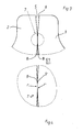
- FIG. 1 shows a formed as a drive seal 1 mechanical seal, consisting of a sliding ring 2, a mating ring 3 and each an elastomeric spring element 4.
- the sliding 2 and the mating ring 3 are approximately in cross section formed angle-shaped and each include a sliding surface 5.6 and a receiving area 5 ', 6' for the spring elements. 4
- FIG. 2 shows a partial view of the sliding ring 2. Visible is the sliding surface 5. In that area of the sliding surface 5, which is marked with an arrow, the sliding surface 5 is provided with a convex contour 7. The sliding surface 5 extends in this example in the radial direction and runs outside of the sliding surface 5 in a trapezoidal surface 8.
- FIG. 3 shows in enlarged form the sliding ring 2, the mating ring 3, the two sliding surfaces 5,6 and the trapezoidal surfaces 8.
- the provided with the convex contour 7 Gleit vomabites is surrounded by a circle.
- FIG. 4 shows area 7 in 50x magnification FIG. 3 ,
- the region 7 in this example in each case has a radius r, r ', which should be identical in this example. It is merely indicated that the sliding surfaces 5, 6 are provided with a coating, for example a chromium layer 9, 9 '.
Landscapes
- Engineering & Computer Science (AREA)
- General Engineering & Computer Science (AREA)
- Mechanical Engineering (AREA)
- Sealing Devices (AREA)
- Mechanical Sealing (AREA)
Description
- Die Erfindung betrifft eine Gleitringdichtung gemäß gattungsbildendem Teil des ersten Patentanspruchs.
- Insbesondere als Laufwerkdichtungen ausgebildete Gleitringdichtungen werden vielfach zur Abdichtung von Laufwerken sowie An-/Abtrieben für geringe Umfangsgeschwindigkeiten bis zu ca. 10 m/s, unter Gewährleistung einer statischen Dichtheit zur Luftseite hin, eingesetzt. Die Gleit- und/oder Gegenringe von Laufwerkdichtungen werden aus harten und verschleißbeständigen metallischen Werkstoffen (Stellite, Stahl, Duronit und ähnliche) erzeugt.
- Die
DE 101 55 653 C2 offenbart eine Gleitringdichtung, insbesondere eine Laufwerkdichtung, umfassend einen winkelförmigen Gleit- und Gegenring, die mit ihren radialen Dichtschenkeln eine Dichtfläche bilden und aus elastomerem Werkstoff bestehenden Dichtkörpern, die zwischen dem die Gleitringdichtung aufnehmenden Gehäuse und der radial äußeren Oberfläche der axialen Schenkel des Gleit- und Gegenringes angeordnet sind. - In der
DE 10 2004 036 974 wird eine Gleitringdichtung, insbesondere eine Laufwerkdichtung, beschrieben, beinhaltend einen Gegen- und einen Gleitring mit je einer Spannfläche zur Aufnahme eines elastomeren Federkörpers, ein dem Gegen- und Gleitring zugeordnetes Gehäuse mit einer Gegenspannfläche für den Federkörper, wobei die Gehäuse ineinander liegend zu einer Einheit verbunden sind und im Bereich des Gegen- und des Gleitringes eine Verdrehsicherung vorgesehen ist. - Durch die
EP 0 779 457 A1 ist eine gattungsgemäße Gleitringdichtung bekannt geworden, bestehend aus einem Gleit- und/oder Gegenring aus metallischem Werkstoff mit einer zur Aufnahme eines elastischen Rollkörpers bestimmten kegeligen Umfangsfläche. Die dem Medium zugekehrte Mantelfläche des Gleit- und/oder Gegenrings ist mit einem eingebrannten Pulverlack beschichtet. - Der
DE 31 41 512 A1 ist ein Gleit- und/oder Gegenring einer Gleitringdichtung zu entnehmen. Bei dieser Gleitringdichtung ist mediumseitig im Bereich des Gleit- und/oder Gegenrings eine Sekundärdichtstelle vorgesehen, die aus einem O-Ring und gegebenenfalls einem Stützring gebildet sein kann. - In der
DE 1 928 675 wird eine berührungslose mit Packungen versehe mechanische Dichtung beschrieben. Die Dichtfläche eines der Ringe ist durch einen Läppvorgang leicht konvex geformt, um dadurch den notwendigen keilförmigen Raum an den äußeren radialen Bereichen des Dichtrings zu schaffen, wodurch die Trennung der Flächen während des Betriebs eingeleitet und beibehalten wird. - In analoger Weise wird auch in der
US 3,905,606 eine berührungslos wirkende Dichtung vorgestellt, bei welcher der mit einem Gehäuse feststehende axial verschiebliche Gleitring ein konvex gekrümmtes Profil besitzt, dessen Krümmungsradien sich von dem Innendurchmesser zum Außendurchmesser des Rings allmählich verkleinern. - Die
US 5,544,896 betrifft eine Gleitringdichtung, bei welcher die Dichtflächen des Gleit- und Gegenringes vollflächig aufeinander liegen und zumindest einer der Dichtringe aus einem Verbundwerkstoff gebildet ist. - Der Erfindung liegt die Aufgabe zugrunde, den technischen Einsatzbereich von Gleitringdichtungen, insbesondere Laufwerkdichtungen, dahingehend zu erweitern, dass selbige auch für Umfangsgeschwindigkeiten oberhalb von 10 m/s, insbesondere für Umfangsgeschwindigkeiten bis 30 m/s, einsetzbar und in der Lage sind, heute gängige Radialwellendichtungen mit deutlich geringerer Lebensdauer zu ersetzen.
- Diese Aufgabe wird dadurch gelöst, dass der Gleitring eine, unter einem Winkel zu der radial verlaufenden Gleitfläche verlaufende, Trapezfläche aufweist und die konvex ausgebildete Kontur im trapeznahen Bereich der Gleitfläche vorgesehen ist.
- Vorteilhafte Weiterbildungen des Erfindungsgegenstandes sind den Unteransprüchen zu entnehmen.
- In seiner einfachsten Ausgestaltungsform beinhaltet die Gleitringdichtung lediglich einen Gleitring in Wirkverbindung mit einem elastomeren Federelement, bei welchem die Gleitfläche mit der erfindungsgemäßen Kontur versehen ist.
- Vom Prinzip her werden zunächst einmal alle geometrischen kurvenförmig ausgebildeten Konturen angesprochen.
- Von besonderem Vorteil ist, wenn die Krümmung nach Art eines Radius ausgebildet ist.
- Die erfindungsgemäße Gleitringdichtung ist im Einsatz als Laufwerkdichtung für deutlich höhere Umfangsgeschwindigkeiten bis 30 m/s einsetzbar und aus diesem Grund in der Lage, Radialwellendichtungen mit deutlich geringerer Lebensdauer zu ersetzen.
- Die jeweilige Kontur wird bevorzugt durch einen Poliervorgang oder eine Drehbearbeitung der Gleitfläche erzeugt.
- Je nach Einsatzfall kann es sinnvoll sein, die Gleitfläche mit einer reibungsarmen Beschichtung zu versehen. Als Beschichtungen bieten sich DLC-, PVD- oder Chromschichten an. Der Fachmann wird, je nach Einsatzfall, die geeignete Art der Beschichtung auswählen.
- Einem weiteren Gedanken der Erfindung gemäß, ist der Gleitring im Querschnitt etwa winkelförmig ausgebildet und weist eine radial verlaufende Gleitfläche sowie eine, unter einem Winkel dazu verlaufende Trapezfläche auf, wobei die Gleitfläche mit der konvex ausgebildeten Kontur, und zwar im trapeznahen Bereich der Gleichfläche versehen ist.
- Eine Laufwerkdichtung besteht vielfach aus einem Gleit- und einem Gegenring, wobei die Gleitflächen einander zugewandt sind. Einem weiteren Gedanken der Erfindung gemäß ist sowohl die Gleitfläche des Gleit- als auch des Gegenrings mit der konvex ausgebildeten Kontur versehen, wobei es von besonderem Vorteil ist, dass die Gleitflächenkonturen im Wesentlichen gleichartig ausgebildet sind.
- Durch die erfindungsgemäße Geometrie der Lauffläche wird die lokale Flächenpressung deutlich reduziert und darüber hinaus zeigen sich auch Vorteile bei möglichen Versatzproblemen zwischen der Gleitfläche des Gleitrings und der Gegenlauffläche, insbesondere der Gegenlauffläche des Gegenrings.
- Der Erfindungsgegenstand ist anhand eines Ausführungsbeispiels in der Zeichnung dargestellt und wird wie folgt beschrieben. Es zeigen:
- Figur 1
- Prinzipskizze einer aus Gleit- und Gegenring bestehenden Laufwerkdichtung;
- Figur 2
- Teildarstellung des Gleitrings;
- Figur 3
- Teildarstellung des Gleit- und Gegenrings;
- Figur 4
- Vergrößerte Darstellung des Gleitbereichs zwischen Gleit- und Gegenring.
-
Figur 1 zeigt eine als Laufwerkdichtung 1 ausgebildete Gleitringdichtung, bestehend aus einem Gleitring 2, einem Gegenring 3 sowie jeweils einem elastomeren Federelement 4. Der Gleit- 2 und der Gegenring 3 sind im Querschnitt etwa winkelförmig ausgebildet und beinhalten jeweils eine Gleitfläche 5,6 sowie einen Aufnahmebereich 5',6' für die Federelemente 4. -
Figur 2 zeigt eine Teildarstellung des Gleitrings 2. Erkennbar ist die Gleitfläche 5. In demjenigen Bereich der Gleitfläche 5, der mit einem Pfeil gekennzeichnet ist, ist die Gleitfläche 5 mit einer konvex ausgebildeten Kontur 7 versehen. Die Gleitfläche 5 verläuft in diesem Beispiel in radialer Richtung und läuft außerhalb der Gleitfläche 5 in einer Trapezfläche 8 aus. -
Figur 3 zeigt in vergrößerter Form den Gleitring 2, den Gegenring 3, die beiden Gleitflächen 5,6 sowie die Trapezflächen 8. Der mit der konvex ausgebildeten Kontur 7 versehene Gleitflächenabschnitt ist mit einem Kreis umgeben. -
Figur 4 zeigt in 50-facher Vergrößerung den Bereich 7 gemäßFigur 3 . Der Bereich 7 umfasst in diesem Beispiel jeweils einen Radius r,r', die in diesem Beispiel gleich ausgebildet sein sollen. Lediglich angedeutet ist, dass die Gleitflächen 5,6 mit einer Beschichtung, beispielsweise einer Chromschicht 9,9' versehen sind.
Claims (8)
- Gleitringdichtung, insbesondere Laufwerkdichtung (1), zumindest beinhaltend einen Gleitring (2), der in Wirkverbindung mit einer Gegenlauffläche, insbesondere einem Gegenring (3), steht, wobei der Gleitring (2) eine Gleitfläche (5) und einen Aufnahmebereich (5',6') für ein elastomeres Federelement (4) aufweist, wobei zumindest die Gleitfläche (5) des Gleitrings (1) mit einer konvex ausgebildeten Kontur versehen ist und der Gleitring (1) im Querschnitt etwa winkelförmig ausgebildet ist und eine radial verlaufende Gleitfläche (5) aufweist, dadurch gekennzeichnet, dass der Gleitring (1) eine, unter einem Winkel zu der radial verlaufenden Gleitfläche (5) verlaufende, Trapezfläche (8) aufweist und die konvex ausgebildete Kontur (7) im trapeznahen Bereich der Gleitfläche (5) vorgesehen ist.
- Gleitringdichtung nach Anspruch 1, dadurch gekennzeichnet, dass die Kontur (7) nach Art einer Kurve mit vorgebbarer Krümmung ausgebildet ist.
- Gleitringdichtung nach Anspruch 1 oder 2, dadurch gekennzeichnet, dass die Krümmung (7) nach Art eines Radius ausgebildet ist.
- Gleitringdichtung nach einem der Ansprüche 1 bis 3, dadurch gekennzeichnet, dass die Kontur (7) durch einen Poliervorgang oder eine Drehbearbeitung der Gleitfläche (5) erzeugt ist.
- Gleitringdichtung nach einem der Ansprüche 1 bis 4, dadurch gekennzeichnet, dass die Gleitfläche (5) mit einer reibungsarmen Beschichtung (9,9') versehen ist.
- Gleitringdichtung nach einem der Ansprüche 1 bis 5, dadurch gekennzeichnet, dass die Beschichtung (9,9') durch eine DLC-, eine PVD- oder eine Chromschicht gebildet ist.
- Gleitringdichtung nach einem der Ansprüche 1 bis 6, beinhaltend einen Gleit- (2) und einen Gegenring (3) mit einander zugewandten Gleitflächen (5,6), dadurch gekennzeichnet, dass die Gleitfläche (5,6) sowohl des Gleit- (2) als auch des Gegenrings (3) mit einer konvex ausgebildeten Kontur (7) versehen ist.
- Gleitringdichtung nach Anspruch 7, dadurch gekennzeichnet, dass die Gleitflächenkonturen (7) im Wesentlichen gleich ausgebildet sind.
Priority Applications (2)
| Application Number | Priority Date | Filing Date | Title |
|---|---|---|---|
| SI201030520T SI2513530T1 (sl) | 2009-12-15 | 2010-12-02 | Tesnilo z drsnim obročem |
| PL10808968T PL2513530T3 (pl) | 2009-12-15 | 2010-12-02 | Uszczelnienie pierścienia ślizgowego |
Applications Claiming Priority (2)
| Application Number | Priority Date | Filing Date | Title |
|---|---|---|---|
| DE102009058315A DE102009058315A1 (de) | 2009-12-15 | 2009-12-15 | Gleitringdichtung |
| PCT/DE2010/001411 WO2011072640A1 (de) | 2009-12-15 | 2010-12-02 | Gleitringdichtung |
Publications (2)
| Publication Number | Publication Date |
|---|---|
| EP2513530A1 EP2513530A1 (de) | 2012-10-24 |
| EP2513530B1 true EP2513530B1 (de) | 2013-11-13 |
Family
ID=43836677
Family Applications (1)
| Application Number | Title | Priority Date | Filing Date |
|---|---|---|---|
| EP10808968.1A Active EP2513530B1 (de) | 2009-12-15 | 2010-12-02 | Gleitringdichtung |
Country Status (6)
| Country | Link |
|---|---|
| US (1) | US9845887B2 (de) |
| EP (1) | EP2513530B1 (de) |
| DE (1) | DE102009058315A1 (de) |
| PL (1) | PL2513530T3 (de) |
| SI (1) | SI2513530T1 (de) |
| WO (1) | WO2011072640A1 (de) |
Families Citing this family (7)
| Publication number | Priority date | Publication date | Assignee | Title |
|---|---|---|---|---|
| GB201116121D0 (en) * | 2011-09-19 | 2011-11-02 | Rolls Royce Plc | Fluid riding device |
| US9279500B2 (en) * | 2012-04-30 | 2016-03-08 | Caterpillar Inc. | Rotary face seal assembly |
| DE102012012085A1 (de) | 2012-06-08 | 2013-12-12 | Emil Nickisch GmbH | Mechanische Laufwerkdichtung mit freigeschnittener Gleitfläche bzw. Schmutzfangnut |
| US9714713B2 (en) * | 2012-12-20 | 2017-07-25 | Caterpillar Inc. | Seal ring with frictional load surface |
| GB201403898D0 (en) * | 2014-03-05 | 2014-04-16 | Eriks Ind Services Ltd | Seal assembly |
| US10724639B2 (en) * | 2018-04-18 | 2020-07-28 | Caterpillar Inc. | Metal face seal taper |
| KR102192185B1 (ko) * | 2020-07-20 | 2020-12-16 | 주식회사 모텍 | 고경도 피막 코팅에 의해 내구성이 크게 개선된 플레인 인케이스드 시일 및 플로팅 시일 |
Family Cites Families (22)
| Publication number | Priority date | Publication date | Assignee | Title |
|---|---|---|---|---|
| DE972262C (de) * | 1944-02-17 | 1959-06-18 | Koppers Gmbh Heinrich | Turmartiger Erhitzer |
| US3180648A (en) * | 1959-12-14 | 1965-04-27 | Caterpillar Tractor Co | Seals |
| US3086782A (en) * | 1959-12-21 | 1963-04-23 | Federal Mogul Bower Bearings | Face seal |
| US3392984A (en) * | 1965-03-29 | 1968-07-16 | Caterpillar Tractor Co | Compact metal face seal for a sealed track |
| US3542377A (en) * | 1968-03-18 | 1970-11-24 | Rex Chainbelt Inc | Secondary seal with sprags |
| US3499653A (en) * | 1968-06-05 | 1970-03-10 | Crane Packing Co | Rotary mechanical seal of the gap type |
| US3623737A (en) * | 1969-12-29 | 1971-11-30 | Caterpillar Tractor Co | Face seals |
| US3767214A (en) * | 1971-06-17 | 1973-10-23 | Komatsu Mfg Co Ltd | Freeze-resisting seal ring |
| DE2222082A1 (de) * | 1972-05-05 | 1973-11-15 | Klein Schanzlin & Becker Ag | Beruehrungsfreie wellendichtung |
| US3905607A (en) * | 1974-02-08 | 1975-09-16 | Caterpillar Tractor Co | Face-type sealing ring with inner seal band |
| JPS589870B2 (ja) * | 1975-08-30 | 1983-02-23 | エヌオーケー株式会社 | メカニカルシ−ル |
| US3985366A (en) * | 1975-10-06 | 1976-10-12 | Caterpillar Tractor Co. | Duo-cone seal flexible mounting |
| US4189159A (en) * | 1978-08-07 | 1980-02-19 | International Harvester Company | Unitized face type seal |
| DE3141512C2 (de) * | 1981-10-20 | 1983-12-08 | Goetze Ag, 5093 Burscheid | Gleitringdichtung |
| US5129688A (en) * | 1990-08-10 | 1992-07-14 | General Components, Inc. | Torque reducing coupling for face seal fittings |
| US5544896A (en) * | 1995-02-06 | 1996-08-13 | Alliedsignal Inc. | Composite face seal |
| DE19546825C2 (de) * | 1995-12-15 | 1998-11-05 | Ae Goetze Gmbh | Gleitringdichtung |
| JP3650954B2 (ja) * | 1998-09-18 | 2005-05-25 | イーグル工業株式会社 | 高速用非接触型メカニカルシール |
| DE10155653C2 (de) | 2001-11-13 | 2003-10-30 | Federal Mogul Friedberg Gmbh | Gleitringdichtung mit geteilten Gleitringen |
| JP2005009530A (ja) * | 2003-06-17 | 2005-01-13 | Eagle Ind Co Ltd | シール装置 |
| DE102004036974B3 (de) | 2004-07-30 | 2005-08-04 | Federal-Mogul Friedberg Gmbh | Gleitringdichtung |
| US20070045966A1 (en) * | 2005-08-31 | 2007-03-01 | Caterpillar Inc. | Coatings for metal-metal seal surfaces |
-
2009
- 2009-12-15 DE DE102009058315A patent/DE102009058315A1/de not_active Withdrawn
-
2010
- 2010-12-02 PL PL10808968T patent/PL2513530T3/pl unknown
- 2010-12-02 SI SI201030520T patent/SI2513530T1/sl unknown
- 2010-12-02 US US13/516,323 patent/US9845887B2/en active Active
- 2010-12-02 WO PCT/DE2010/001411 patent/WO2011072640A1/de active Application Filing
- 2010-12-02 EP EP10808968.1A patent/EP2513530B1/de active Active
Also Published As
| Publication number | Publication date |
|---|---|
| SI2513530T1 (sl) | 2014-03-31 |
| US20120248706A1 (en) | 2012-10-04 |
| EP2513530A1 (de) | 2012-10-24 |
| DE102009058315A1 (de) | 2011-06-16 |
| US9845887B2 (en) | 2017-12-19 |
| WO2011072640A1 (de) | 2011-06-23 |
| PL2513530T3 (pl) | 2014-04-30 |
Similar Documents
| Publication | Publication Date | Title |
|---|---|---|
| EP2513530B1 (de) | Gleitringdichtung | |
| EP2118534B1 (de) | Kolbenring mit mehrlagenschichtverband und verfahren zu dessen herstellung | |
| EP2663791B1 (de) | Wellendichtungseinsatz | |
| DE112010005439T5 (de) | Wälzlager umfassend eine Dichtung und ein ringförmiges Schutzschild | |
| DE102006026812A1 (de) | Dichtung | |
| DE102006025799A1 (de) | Dichtelement | |
| EP2150732B1 (de) | Kolbenring | |
| DE102014110907A1 (de) | Gleitlagervorrichtung | |
| DE102013214370A1 (de) | Nehmerzylinder für eine hydraulische Ausrückanordnung zur Betätigung einer Kupplung | |
| WO2012069407A1 (de) | Radialwellendichtring | |
| DE112007000383T5 (de) | Robustes Dichtungssystem für Servolenkungs-Eingangswelle | |
| WO2012017094A2 (de) | Anordnung zum abdichten einer drehverbindung | |
| DE102007029992A1 (de) | Kolbenring | |
| DE102012207745A1 (de) | Pendelrollenlager mit Dichtscheibe | |
| DE102010018552A1 (de) | Dichtungsanordnung und Gelenk einer Kette mit der Dichtungsanordnung | |
| EP1717493B1 (de) | Schraubendruckfeder für Ölabstreifkolbenringe | |
| WO2007016980A1 (de) | Elastomer-wellendichtring | |
| DE102011107794A1 (de) | Drosselklappeneinrichtung | |
| DE19546825C2 (de) | Gleitringdichtung | |
| AT500162A1 (de) | Gleitringdichtung | |
| EP1288538A2 (de) | Abstreifer | |
| DE3203374A1 (de) | Sitzring fuer klappwellen bei absperrklappen u.dgl. | |
| DE19707652C2 (de) | Dichtring | |
| EP3555503A1 (de) | Vorrichtung zur abdichtung eines gegenstands | |
| DE102011075043B4 (de) | Dichtung für Schaltventile |
Legal Events
| Date | Code | Title | Description |
|---|---|---|---|
| PUAI | Public reference made under article 153(3) epc to a published international application that has entered the european phase |
Free format text: ORIGINAL CODE: 0009012 |
|
| 17P | Request for examination filed |
Effective date: 20120426 |
|
| AK | Designated contracting states |
Kind code of ref document: A1 Designated state(s): AL AT BE BG CH CY CZ DE DK EE ES FI FR GB GR HR HU IE IS IT LI LT LU LV MC MK MT NL NO PL PT RO RS SE SI SK SM TR |
|
| DAX | Request for extension of the european patent (deleted) | ||
| GRAP | Despatch of communication of intention to grant a patent |
Free format text: ORIGINAL CODE: EPIDOSNIGR1 |
|
| INTG | Intention to grant announced |
Effective date: 20130726 |
|
| GRAS | Grant fee paid |
Free format text: ORIGINAL CODE: EPIDOSNIGR3 |
|
| GRAA | (expected) grant |
Free format text: ORIGINAL CODE: 0009210 |
|
| AK | Designated contracting states |
Kind code of ref document: B1 Designated state(s): AL AT BE BG CH CY CZ DE DK EE ES FI FR GB GR HR HU IE IS IT LI LT LU LV MC MK MT NL NO PL PT RO RS SE SI SK SM TR |
|
| REG | Reference to a national code |
Ref country code: GB Ref legal event code: FG4D Free format text: NOT ENGLISH |
|
| REG | Reference to a national code |
Ref country code: CH Ref legal event code: EP |
|
| REG | Reference to a national code |
Ref country code: AT Ref legal event code: REF Ref document number: 640719 Country of ref document: AT Kind code of ref document: T Effective date: 20131215 |
|
| REG | Reference to a national code |
Ref country code: IE Ref legal event code: FG4D Free format text: LANGUAGE OF EP DOCUMENT: GERMAN |
|
| REG | Reference to a national code |
Ref country code: DE Ref legal event code: R096 Ref document number: 502010005390 Country of ref document: DE Effective date: 20140102 |
|
| REG | Reference to a national code |
Ref country code: NL Ref legal event code: VDEP Effective date: 20131113 |
|
| REG | Reference to a national code |
Ref country code: LT Ref legal event code: MG4D |
|
| PG25 | Lapsed in a contracting state [announced via postgrant information from national office to epo] |
Ref country code: SE Free format text: LAPSE BECAUSE OF FAILURE TO SUBMIT A TRANSLATION OF THE DESCRIPTION OR TO PAY THE FEE WITHIN THE PRESCRIBED TIME-LIMIT Effective date: 20131113 Ref country code: IS Free format text: LAPSE BECAUSE OF FAILURE TO SUBMIT A TRANSLATION OF THE DESCRIPTION OR TO PAY THE FEE WITHIN THE PRESCRIBED TIME-LIMIT Effective date: 20140313 Ref country code: NL Free format text: LAPSE BECAUSE OF FAILURE TO SUBMIT A TRANSLATION OF THE DESCRIPTION OR TO PAY THE FEE WITHIN THE PRESCRIBED TIME-LIMIT Effective date: 20131113 Ref country code: FI Free format text: LAPSE BECAUSE OF FAILURE TO SUBMIT A TRANSLATION OF THE DESCRIPTION OR TO PAY THE FEE WITHIN THE PRESCRIBED TIME-LIMIT Effective date: 20131113 Ref country code: LT Free format text: LAPSE BECAUSE OF FAILURE TO SUBMIT A TRANSLATION OF THE DESCRIPTION OR TO PAY THE FEE WITHIN THE PRESCRIBED TIME-LIMIT Effective date: 20131113 Ref country code: NO Free format text: LAPSE BECAUSE OF FAILURE TO SUBMIT A TRANSLATION OF THE DESCRIPTION OR TO PAY THE FEE WITHIN THE PRESCRIBED TIME-LIMIT Effective date: 20140213 Ref country code: HR Free format text: LAPSE BECAUSE OF FAILURE TO SUBMIT A TRANSLATION OF THE DESCRIPTION OR TO PAY THE FEE WITHIN THE PRESCRIBED TIME-LIMIT Effective date: 20131113 |
|
| REG | Reference to a national code |
Ref country code: PL Ref legal event code: T3 |
|
| PG25 | Lapsed in a contracting state [announced via postgrant information from national office to epo] |
Ref country code: ES Free format text: LAPSE BECAUSE OF FAILURE TO SUBMIT A TRANSLATION OF THE DESCRIPTION OR TO PAY THE FEE WITHIN THE PRESCRIBED TIME-LIMIT Effective date: 20131113 Ref country code: LV Free format text: LAPSE BECAUSE OF FAILURE TO SUBMIT A TRANSLATION OF THE DESCRIPTION OR TO PAY THE FEE WITHIN THE PRESCRIBED TIME-LIMIT Effective date: 20131113 Ref country code: CY Free format text: LAPSE BECAUSE OF FAILURE TO SUBMIT A TRANSLATION OF THE DESCRIPTION OR TO PAY THE FEE WITHIN THE PRESCRIBED TIME-LIMIT Effective date: 20131113 Ref country code: RS Free format text: LAPSE BECAUSE OF FAILURE TO SUBMIT A TRANSLATION OF THE DESCRIPTION OR TO PAY THE FEE WITHIN THE PRESCRIBED TIME-LIMIT Effective date: 20131113 |
|
| REG | Reference to a national code |
Ref country code: SK Ref legal event code: T3 Ref document number: E 15823 Country of ref document: SK |
|
| BERE | Be: lapsed |
Owner name: FEDERAL-MOGUL BURSCHEID G.M.B.H. Effective date: 20131231 |
|
| PG25 | Lapsed in a contracting state [announced via postgrant information from national office to epo] |
Ref country code: PT Free format text: LAPSE BECAUSE OF FAILURE TO SUBMIT A TRANSLATION OF THE DESCRIPTION OR TO PAY THE FEE WITHIN THE PRESCRIBED TIME-LIMIT Effective date: 20140313 |
|
| PG25 | Lapsed in a contracting state [announced via postgrant information from national office to epo] |
Ref country code: EE Free format text: LAPSE BECAUSE OF FAILURE TO SUBMIT A TRANSLATION OF THE DESCRIPTION OR TO PAY THE FEE WITHIN THE PRESCRIBED TIME-LIMIT Effective date: 20131113 |
|
| REG | Reference to a national code |
Ref country code: DE Ref legal event code: R097 Ref document number: 502010005390 Country of ref document: DE |
|
| PG25 | Lapsed in a contracting state [announced via postgrant information from national office to epo] |
Ref country code: CZ Free format text: LAPSE BECAUSE OF FAILURE TO SUBMIT A TRANSLATION OF THE DESCRIPTION OR TO PAY THE FEE WITHIN THE PRESCRIBED TIME-LIMIT Effective date: 20131113 Ref country code: RO Free format text: LAPSE BECAUSE OF FAILURE TO SUBMIT A TRANSLATION OF THE DESCRIPTION OR TO PAY THE FEE WITHIN THE PRESCRIBED TIME-LIMIT Effective date: 20131113 |
|
| PLBE | No opposition filed within time limit |
Free format text: ORIGINAL CODE: 0009261 |
|
| STAA | Information on the status of an ep patent application or granted ep patent |
Free format text: STATUS: NO OPPOSITION FILED WITHIN TIME LIMIT |
|
| REG | Reference to a national code |
Ref country code: IE Ref legal event code: MM4A |
|
| PG25 | Lapsed in a contracting state [announced via postgrant information from national office to epo] |
Ref country code: DK Free format text: LAPSE BECAUSE OF FAILURE TO SUBMIT A TRANSLATION OF THE DESCRIPTION OR TO PAY THE FEE WITHIN THE PRESCRIBED TIME-LIMIT Effective date: 20131113 |
|
| 26N | No opposition filed |
Effective date: 20140814 |
|
| PG25 | Lapsed in a contracting state [announced via postgrant information from national office to epo] |
Ref country code: BE Free format text: LAPSE BECAUSE OF NON-PAYMENT OF DUE FEES Effective date: 20131231 Ref country code: IE Free format text: LAPSE BECAUSE OF NON-PAYMENT OF DUE FEES Effective date: 20131202 |
|
| REG | Reference to a national code |
Ref country code: DE Ref legal event code: R097 Ref document number: 502010005390 Country of ref document: DE Effective date: 20140814 |
|
| PG25 | Lapsed in a contracting state [announced via postgrant information from national office to epo] |
Ref country code: MC Free format text: LAPSE BECAUSE OF FAILURE TO SUBMIT A TRANSLATION OF THE DESCRIPTION OR TO PAY THE FEE WITHIN THE PRESCRIBED TIME-LIMIT Effective date: 20131113 |
|
| PG25 | Lapsed in a contracting state [announced via postgrant information from national office to epo] |
Ref country code: SM Free format text: LAPSE BECAUSE OF FAILURE TO SUBMIT A TRANSLATION OF THE DESCRIPTION OR TO PAY THE FEE WITHIN THE PRESCRIBED TIME-LIMIT Effective date: 20131113 |
|
| PG25 | Lapsed in a contracting state [announced via postgrant information from national office to epo] |
Ref country code: MK Free format text: LAPSE BECAUSE OF FAILURE TO SUBMIT A TRANSLATION OF THE DESCRIPTION OR TO PAY THE FEE WITHIN THE PRESCRIBED TIME-LIMIT Effective date: 20131113 Ref country code: HU Free format text: LAPSE BECAUSE OF FAILURE TO SUBMIT A TRANSLATION OF THE DESCRIPTION OR TO PAY THE FEE WITHIN THE PRESCRIBED TIME-LIMIT; INVALID AB INITIO Effective date: 20101202 Ref country code: BG Free format text: LAPSE BECAUSE OF FAILURE TO SUBMIT A TRANSLATION OF THE DESCRIPTION OR TO PAY THE FEE WITHIN THE PRESCRIBED TIME-LIMIT Effective date: 20131113 Ref country code: LU Free format text: LAPSE BECAUSE OF NON-PAYMENT OF DUE FEES Effective date: 20131202 |
|
| REG | Reference to a national code |
Ref country code: CH Ref legal event code: PL |
|
| PG25 | Lapsed in a contracting state [announced via postgrant information from national office to epo] |
Ref country code: MT Free format text: LAPSE BECAUSE OF FAILURE TO SUBMIT A TRANSLATION OF THE DESCRIPTION OR TO PAY THE FEE WITHIN THE PRESCRIBED TIME-LIMIT Effective date: 20131113 Ref country code: GR Free format text: LAPSE BECAUSE OF NON-PAYMENT OF DUE FEES Effective date: 20131113 |
|
| PG25 | Lapsed in a contracting state [announced via postgrant information from national office to epo] |
Ref country code: CH Free format text: LAPSE BECAUSE OF NON-PAYMENT OF DUE FEES Effective date: 20141231 Ref country code: LI Free format text: LAPSE BECAUSE OF NON-PAYMENT OF DUE FEES Effective date: 20141231 |
|
| REG | Reference to a national code |
Ref country code: FR Ref legal event code: PLFP Year of fee payment: 6 |
|
| PG25 | Lapsed in a contracting state [announced via postgrant information from national office to epo] |
Ref country code: GR Free format text: LAPSE BECAUSE OF FAILURE TO SUBMIT A TRANSLATION OF THE DESCRIPTION OR TO PAY THE FEE WITHIN THE PRESCRIBED TIME-LIMIT Effective date: 20140214 |
|
| REG | Reference to a national code |
Ref country code: FR Ref legal event code: PLFP Year of fee payment: 7 |
|
| REG | Reference to a national code |
Ref country code: AT Ref legal event code: MM01 Ref document number: 640719 Country of ref document: AT Kind code of ref document: T Effective date: 20151202 |
|
| PG25 | Lapsed in a contracting state [announced via postgrant information from national office to epo] |
Ref country code: AT Free format text: LAPSE BECAUSE OF NON-PAYMENT OF DUE FEES Effective date: 20151202 |
|
| REG | Reference to a national code |
Ref country code: FR Ref legal event code: PLFP Year of fee payment: 8 |
|
| PG25 | Lapsed in a contracting state [announced via postgrant information from national office to epo] |
Ref country code: AL Free format text: LAPSE BECAUSE OF FAILURE TO SUBMIT A TRANSLATION OF THE DESCRIPTION OR TO PAY THE FEE WITHIN THE PRESCRIBED TIME-LIMIT Effective date: 20131113 |
|
| PGFP | Annual fee paid to national office [announced via postgrant information from national office to epo] |
Ref country code: IT Payment date: 20221122 Year of fee payment: 13 |
|
| P01 | Opt-out of the competence of the unified patent court (upc) registered |
Effective date: 20230528 |
|
| PGFP | Annual fee paid to national office [announced via postgrant information from national office to epo] |
Ref country code: SK Payment date: 20231128 Year of fee payment: 14 |
|
| PGFP | Annual fee paid to national office [announced via postgrant information from national office to epo] |
Ref country code: GB Payment date: 20231121 Year of fee payment: 14 |
|
| PGFP | Annual fee paid to national office [announced via postgrant information from national office to epo] |
Ref country code: TR Payment date: 20231123 Year of fee payment: 14 Ref country code: SI Payment date: 20231128 Year of fee payment: 14 Ref country code: FR Payment date: 20231122 Year of fee payment: 14 Ref country code: DE Payment date: 20231121 Year of fee payment: 14 |
|
| PGFP | Annual fee paid to national office [announced via postgrant information from national office to epo] |
Ref country code: PL Payment date: 20231122 Year of fee payment: 14 |