EP2513461B1 - Kolben für einen verbrennungsmotor - Google Patents
Kolben für einen verbrennungsmotor Download PDFInfo
- Publication number
- EP2513461B1 EP2513461B1 EP10803553.6A EP10803553A EP2513461B1 EP 2513461 B1 EP2513461 B1 EP 2513461B1 EP 10803553 A EP10803553 A EP 10803553A EP 2513461 B1 EP2513461 B1 EP 2513461B1
- Authority
- EP
- European Patent Office
- Prior art keywords
- piston
- ring belt
- support element
- box
- walls
- Prior art date
- Legal status (The legal status is an assumption and is not a legal conclusion. Google has not performed a legal analysis and makes no representation as to the accuracy of the status listed.)
- Active
Links
Images


Classifications
-
- F—MECHANICAL ENGINEERING; LIGHTING; HEATING; WEAPONS; BLASTING
- F02—COMBUSTION ENGINES; HOT-GAS OR COMBUSTION-PRODUCT ENGINE PLANTS
- F02F—CYLINDERS, PISTONS OR CASINGS, FOR COMBUSTION ENGINES; ARRANGEMENTS OF SEALINGS IN COMBUSTION ENGINES
- F02F3/00—Pistons
- F02F3/0076—Pistons the inside of the pistons being provided with ribs or fins
-
- F—MECHANICAL ENGINEERING; LIGHTING; HEATING; WEAPONS; BLASTING
- F02—COMBUSTION ENGINES; HOT-GAS OR COMBUSTION-PRODUCT ENGINE PLANTS
- F02F—CYLINDERS, PISTONS OR CASINGS, FOR COMBUSTION ENGINES; ARRANGEMENTS OF SEALINGS IN COMBUSTION ENGINES
- F02F3/00—Pistons
-
- F—MECHANICAL ENGINEERING; LIGHTING; HEATING; WEAPONS; BLASTING
- F16—ENGINEERING ELEMENTS AND UNITS; GENERAL MEASURES FOR PRODUCING AND MAINTAINING EFFECTIVE FUNCTIONING OF MACHINES OR INSTALLATIONS; THERMAL INSULATION IN GENERAL
- F16J—PISTONS; CYLINDERS; SEALINGS
- F16J1/00—Pistons; Trunk pistons; Plungers
-
- F—MECHANICAL ENGINEERING; LIGHTING; HEATING; WEAPONS; BLASTING
- F16—ENGINEERING ELEMENTS AND UNITS; GENERAL MEASURES FOR PRODUCING AND MAINTAINING EFFECTIVE FUNCTIONING OF MACHINES OR INSTALLATIONS; THERMAL INSULATION IN GENERAL
- F16J—PISTONS; CYLINDERS; SEALINGS
- F16J9/00—Piston-rings, e.g. non-metallic piston-rings, seats therefor; Ring sealings of similar construction
Definitions
- the present invention relates to a piston for an internal combustion engine, with a piston crown, a circumferential top land and a circumferential ring section having annular grooves, and with a piston skirt which has two skirt walls and two box walls that are set back from the ring section and connect the skirt walls, so that in the area of the box walls in each case a free-standing underside of the ring belt is formed, the box walls being provided with pin hubs having pin bores.
- a generic piston is from the international patent application WO 2008/128611 A1 as well as from the European patent application EP 0 838 587 A1 known.
- Pistons of this type are also referred to as box pistons.
- box-type pistons two opposing walls of the piston skirt are set back with respect to the outer contour of the piston.
- the recessed walls are called box walls, the other two walls that are not recessed are the skirt walls and have the actual running surface of the piston skirt.
- the pin hubs with the hub bores are integrated into the box walls.
- the box walls and the skirt walls are connected to the underside of the piston crown.
- a particular disadvantage here is that the ring belt is only supported in the area of the skirt walls, but has a free-standing, overhanging underside in the area of the box walls. As a result, the ring belt in the area of the box walls is clearly deformed in the direction of the crankcase.
- the ring belt in the area of the skirt walls is only slightly deformed due to the rigid construction of the box walls and the skirt walls. There is therefore a jump in rigidity in the area in which the box walls merge into the shaft walls.
- a piston in which a support element is present between a free-standing underside of the ring belt and the box wall assigned to it, which is designed as a rib with an arcuate geometry.
- the object of the present invention is thus to develop a generic box piston in such a way that the load due to the bending moment occurring during engine operation is reduced in the area of the ring belt and that a supporting effect and power transmission are optimized.
- the solution is that at least one support element is arranged between each free-standing underside of the ring section and the box wall assigned to it, and that the at least one support element extends over the entire radial width of the free-standing underside of the ring section, the at least one support element being tetrahedral and in the Cross-section is triangular or trapezoidal.
- An advantageous further development consists in that between each free-standing underside of the ring belt and the box wall assigned to it, precisely one support element arranged above the hub bore is provided. An effective reduction in the deflection is achieved in that precisely one support element connects the ring section to the box wall in the region of the maximum deflection.
- Each support element can extend in a circumferential direction over the entire box wall. This results in a particularly effective stiffening of the ring belt.
- a particularly preferred development consists in that exactly two support elements are provided between each free-standing underside of the ring belt and the box wall assigned to it, which support elements are arranged on both sides of the hub bore. This achieves a very effective stiffening of the ring belt in the area of the box walls and, at the same time, an optimal ratio between the stiffening on the one hand and the weight of the piston on the other hand.
- the support elements can extend so far over the box walls that they at least partially enclose the hub bore. As a result, the forces acting on the ring belt can be diverted particularly effectively into the box walls.
- the at least one support element is tetrahedral and has a triangular or trapezoidal cross section.
- the support effect and the power transmission are optimized.
- the present invention is suitable for all types of box piston. It can be used in particular in multi-part pistons which have an upper piston part and a lower piston part which includes the at least one support element and which are connected to one another by means of a suitable welding process.
- the at least one support element according to the invention significantly reduces the load on the weld seams, which is caused by the bending moments occurring when the ring section is bent in the area of the box walls, so that the component safety of such pistons is significantly improved.
- the piston can be made of any material, in particular a steel material.
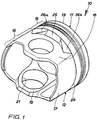
- the Figures 1 to 4 show an exemplary embodiment of a piston 10 according to the invention, which in the exemplary embodiment is forged from a steel material.
- the piston 10 according to the invention is a two-part piston in the exemplary embodiment. It is composed of an upper piston part 11 and a lower piston part 12.
- the upper piston part 11 has a piston head 13 with a combustion bowl 13a and a circumferential ring belt 15 that includes a top land 14.
- the piston lower part 12 has a piston skirt 16 which is connected to the underside of the piston head 13.
- the piston skirt 16 has two skirt walls 17 and two box walls 18 that are set back with respect to the ring belt 15 and connect the skirt walls 17. As a result, there is a free-standing underside 25 of the ring belt 15 educated.
- the outer circumferential surface of each skirt wall 17 represents a running surface of the piston skirt 16.
- Each box wall 18 has a pin boss 19 provided with a pin bore 21.
- the upper piston part 11 and the lower piston part 12 form a circumferential outer cooling channel 22 in the area of the ring belt.
- the upper piston part 11 and the lower piston part 12 are connected in a manner known per se by means of a suitable connection method, for example by friction welding. As a result, an inner circumferential weld seam 23 and an outer circumferential weld seam 24 are formed.
- each free-standing underside 25 of the ring belt 15 is connected to the box wall 18 assigned to it by means of two support elements 26a, 26b.
- the support elements 26a, 26b are integrally formed on the piston lower part 12, for example, forged, and arranged on both sides of each hub bore 21.
- the support elements 26a, 26b are approximately tetrahedral with an approximately triangular cross-section, the tip of each support element 26a, 26b being aligned with the hub bore 21 of the respective box wall 18.
- each approximately tetrahedral support element 26a, 26b extends along the free-standing underside 25 of the ring section 15 and is dimensioned in the exemplary embodiment such that each support element 26a, 26b extends over the entire radial width of the free-standing underside 25 of the ring section 15 (cf. Figures 1 and 3 ).
- the support elements have the effect that the deformation of the ring belt 15 is significantly reduced during engine operation. In this way, the stresses resulting from this deformation, which occur in particular in the transition area between each shaft wall 17 and each box wall 18, are also reduced. This has the consequence that the stress on the weld seams 23, 24 and also on the piston crown is greatly reduced and the component safety of the piston 10 according to the invention is significantly increased.
Landscapes
- Engineering & Computer Science (AREA)
- General Engineering & Computer Science (AREA)
- Mechanical Engineering (AREA)
- Chemical & Material Sciences (AREA)
- Combustion & Propulsion (AREA)
- Pistons, Piston Rings, And Cylinders (AREA)
Description
- Die vorliegende Erfindung betrifft einen Kolben für einen Verbrennungsmotor, mit einem Kolbenboden, einem umlaufenden Feuersteg und einer Ringnuten aufweisenden umlaufenden Ringpartie sowie mit einem Kolbenschaft, der zwei Schaftwände und zwei gegenüber der Ringpartie zurückgesetzte, die Schaftwände verbindende Kastenwände aufweist, derart dass im Bereich der Kastenwände jeweils eine freistehende Unterseite der Ringpartie gebildet ist, wobei die Kastenwände mit Nabenbohrungen aufweisenden Bolzennaben versehen sind.
- Ein gattungsgemäßer Kolben ist aus der internationalen Patentanmeldung
WO 2008/128611 A1 sowie aus der europäischen PatentanmeldungEP 0 838 587 A1 bekannt. Kolben dieser Bauweise werden auch als Kastenkolben bezeichnet. Bei typischen Kastenkolben sind zwei einander gegenüber liegende Wände des Kolbenschaftes gegenüber der äußeren Kontur des Kolbens zurückgesetzt. Die zurückgesetzten Wände werden als Kastenwände bezeichnet, die beiden anderen nicht zurückgesetzten Wände sind die Schaftwände und weisen die eigentliche Lauffläche des Kolbenschaftes auf. In die Kastenwände sind die Bolzennaben mit den Nabenbohrungen integriert. Die Kastenwände und die Schaftwände sind mit der Unterseite des Kolbenbodens verbunden. - Bei derartigen Kastenkolben tritt das Problem auf, dass im Motorbetrieb durch den Gasdruck und den Zünddruck so große Kräfte auf den Kolben einwirken, dass Deformationen am Kolben auftreten. Besonders nachteilig ist hierbei, dass die Ringpartie nur im Bereich der Schaftwände unterstützt ist, im Bereich der Kastenwände jedoch eine freistehende, überhängende Unterseite aufweisen. Dies hat zur Folge, dass die Ringpartie im Bereich der Kastenwände deutlich in Richtung des Kurbelgehäuses deformiert wird. Die Ringpartie im Bereich der Schaftwände wird dagegen infolge der steifen Konstruktion der Kastenwände und der Schaftwände nur geringfügig deformiert. Es liegt daher ein Steifigkeitssprung in dem Bereich vor, in dem die Kastenwände in die Schaftwände übergehen. Dadurch und durch das bei der Deformation der Ringpartie im Bereich der Kastenwände auftretende Biegemoment treten Spannungen auf, durch die der Kastenkolben übermäßig belastet wird. Insbesondere in dem Fall, in dem der Kastenkolben aus einem Oberteil und einem Unterteil besteht, die miteinander verschweißt sind, wird die Schweißnaht bzw. werden die Schweißnähte besonders stark belastet, was zum Aufbrechen der Schweißnaht im Bereich der Übergänge zwischen einer Kastenwand und einer Schaftwand führen kann. In dem Fall, dass der Kolben ferner einen umlaufenden Kühlkanal im Bereich der Ringpartie aufweist, wird dadurch die Stabilität der Ringpartie weiter reduziert, so dass im Motorbetrieb eine besonders deutliche Deformation beobachtet wird.
- Vor diesem Hintergrund ist aus der
DE 10 2007 020 447 A1 ein Kolben bekannt, bei welchem zwischen einer freistehenden Unterseite der Ringpartie und der ihr zugeordneten Kastenwand ein Stützelement vorhanden ist, das als Rippe mit bogenförmiger Geometrie ausgebildet ist. -
DE 10 2007 020 447 A1 offenbart einen Kolben nach dem Oberbegriff des Anspruchs 1. - Die Aufgabe der vorliegenden Erfindung besteht somit darin, einen gattungsgemäßen Kastenkolben so weiterzubilden, dass die Belastung durch das im Motorbetrieb auftretende Biegemoment im Bereich der Ringpartie reduziert wird und dass eine Stützwirkung und eine Kraftübertragung optimiert werden.
- Die Lösung besteht darin, dass zwischen jeder freistehenden Unterseite der Ringpartie und der ihr zugeordneten Kastenwand mindestens ein Stützelement angeordnet ist, und dass das mindestens eine Stützelement sich über die gesamte radiale Breite der freistehenden Unterseite der Ringpartie erstreckt, wobei das mindestens einen Stützelement tetraederförmig und im Querschnitt dreieckig oder trapezförmig ausgebildet ist.
- Es hat sich überraschend herausgestellt, dass durch die Anbindung der freistehenden Unterseiten der Ringpartie an die Kastenwände mit Hilfe mindestens eines Stützelements, dass sich über die gesamte radiale Breite der freistehenden Unterseite der Ringpartie erstreckt, die auf den erfindungsgemäßen Kolben wirkende Belastung deutlich reduziert wird, weil die Ringpartie in diesem Bereich im Motorbetrieb weniger stark deformiert wird. Insbesondere bei mehrteiligen geschweißten Kolben wird die Belastung der Schweißnähte deutlich vermindert und die Bauteilsicherheit entsprechend erhöht. Es entfällt die Notwendigkeit, die Ringpartie zu verstärken und/oder die Kastenwände radial nach außen zu versetzen. Die durch das mindestens eine Stützelement bedingte Vergrößerung des Gewichts des Kastenkolbens ist minimal.
- Vorteilhafte Weiterbildungen ergeben sich aus den Unteransprüchen.
- Eine vorteilhafte Weiterbildung besteht darin, dass zwischen jeder freistehenden Unterseite der Ringpartie und der ihr zugeordneten Kastenwand genau ein oberhalb der Nabenbohrung angeordnetes Stützelement vorgesehen ist. Eine wirksame Reduzierung der Durchbiegung wird bereits dadurch erzielt, dass genau ein Stützelement im Bereich der maximalen Durchbiegung der Ringpartie diese an die Kastenwand anbindet.
- Jedes Stützelement kann sich in umlaufender Richtung über die gesamte Kastenwand erstrecken. Dies resultiert in einer besonders wirksamen Versteifung der Ringpartie.
- Eine besonders bevorzugte Weiterbildung besteht darin, dass zwischen jeder freistehenden Unterseite der Ringpartie und der ihr zugeordneten Kastenwand genau zwei Stützelemente vorgesehen sind, die beidseits der Nabenbohrung angeordnet sind. Dadurch wird eine sehr wirksame Versteifung der Ringpartie im Bereich der Kastenwände erzielt und, zugleich wird ein optimales Verhältnis zwischen der Versteifung einerseits und dem Gewicht des Kolbens andererseits erreicht.
- Die Stützelemente können sich so weit über die Kastenwände erstrecken, dass sie die Nabenbohrung zumindest teilweise umschließen. Dadurch können die auf die Ringpartie wirkenden Kräfte besonders effektiv in die Kastenwände abgeleitet werden.
- Erfindungsgemäß ist das mindestens eine Stützelement tetraederförmig und im Querschnitt dreieckig oder trapezförmig ausgebildet. Dabei werden die Stützwirkung und die Kraftübertragung optimiert.
- Die vorliegende Erfindung ist für alle Bautypen von Kastenkolben geeignet. Sie kann insbesondere bei mehrteiligen Kolben zum Einsatz kommen, die ein Kolbenoberteil und ein das mindestens eine Stützelement umfassendes Kolbenunterteil aufweisen, die mittels eines geeigneten Schweißverfahrens miteinander verbunden sind. Durch das erfindungsgemäße mindestens eine Stützelement wird die Belastung der Schweißnähte, die von den bei der Durchbiegung der Ringpartie im Bereich der Kastenwände auftretenden Biegemomenten verursacht wird, deutlich reduziert, so dass die Bauteilsicherheit derartiger Kolben wesentlich verbessert wird. Der Kolben kann aus beliebigen Werkstoffen hergestellt sein, insbesondere aus einem Stahlwerkstoff.
- Ein Ausführungsbeispiel der vorliegenden Erfindung wird im Folgenden anhand der beigefügten Zeichnungen näher erläutert. Es zeigen in einer schematischen, nicht maßstabsgetreuen Darstellung:
- Figur 1
- eine perspektivische Darstellung eines Ausführungsbeispiels eines erfin-dungsgemäßen Kolbens;
- Figur 2
- den Kolben gemäß
Figur 1 in einer Frontansicht; - Figur 3
- den Kolben gemäß
Figur 1 in einer gegenüberFigur 2 um 90° gedrehten Seitenansicht; - Figur 4
- einen Schnitt entlang der Linie IV - IV in
Figur 2 . - Die
Figuren 1 bis 4 zeigen ein Ausführungsbeispiel eines erfindungsgemäßen Kolbens 10, der im Ausführungsbeispiel aus einem Stahlwerkstoff geschmiedet ist. Der erfindungsgemäße Kolben 10 ist im Ausführungsbeispiel ein zweiteiliger Kolben. Er setzt sich zusammen aus einem Kolbenoberteil 11 und einem Kolbenunterteil 12. Das Kolbenoberteil 11 weist einen Kolbenboden 13 mit einer Verbrennungsmulde 13a und eine umlaufende, einen Feuersteg 14 einschließenden, Ringpartie 15 auf. Das Kolbenunterteil 12 weist einen Kolbenschaft 16 auf, der an der Unterseite des Kolbenbodens 13 angebunden ist. Der Kolbenschaft 16 weist zwei Schaftwände 17 und zwei gegenüber der Ringpartie 15 zurückgesetzte, die Schaftwände 17 verbindende Kastenwände 18 auf. Dadurch ist eine freistehende Unterseite 25 der Ringpartie 15 gebildet. Die Außenumfangsfläche jeder Schaftwand 17 stellt eine Lauffläche des Kolbenschaftes 16 dar. Jede Kastenwand 18 weist eine mit einer Nabenbohrung 21 versehene Bolzennabe 19 auf. - Das Kolbenoberteil 11 und das Kolbenunterteil 12 bilden im Bereich der Ringpartie einen umlaufenden äußeren Kühlkanal 22.
- Das Kolbenoberteil 11 und das Kolbenunterteil 12 sind im Ausführungsbeispiel in an sich bekannter Weise mittels eines geeigneten Verbindungsverfahrens, bspw. durch Reibschweißen, verbunden. Dadurch werden eine innere umlaufende Schweißnaht 23 und eine äußere umlaufende Schweißnaht 24 gebildet.
- Im Ausführungsbeispiel ist jede freistehende Unterseite 25 der Ringpartie 15 mittels zweier Stützelemente 26a, 26b an die ihr zugeordnete Kastenwand 18 angebunden. Die Stützelemente 26a, 26b sind im Ausführungsbeispiel einstückig an das Kolbenunterteil 12 angeformt, bspw. geschmiedet und beidseits jeder Nabenbohrung 21 angeordnet. Die Stützelemente 26a, 26b sind etwa tetraederförmig mit in etwa dreieckigem Querschnitt ausgebildet, wobei die Spitze jedes Stützelements 26a, 26b, zur Nabenbohrung 21 der jeweiligen Kastenwand 18 ausgerichtet ist. Die Basis jedes etwa tetraederförmigen Stützelements 26a, 26b erstreckt sich entlang der freistehenden Unterseite 25 der Ringpartie 15 und ist im Ausführungsbeispiel so bemessen, dass jedes Stützelement 26a, 26b sich über die gesamte radiale Breite der freistehenden Unterseite 25 der Ringpartie 15 erstreckt (vgl.
Figuren 1 und3 ). - Selbstverständlich kann auch nur ein Stützelement vorgesehen sein, das oberhalb der Nabenbohrung 21 angeordnet ist. In jedem Fall bewirken die Stützelemente, dass die Deformation der Ringpartie 15 im Motorbetrieb wesentlich reduziert wird. Damit werden die aus dieser Deformation resultierenden Spannungen, die insbesondere im Übergangsbereich zwischen jeder Schaftwand 17 und jeder Kastenwand 18 auftreten, ebenfalls reduziert. Dies hat zur Folge, dass die Beanspruchung der Schweißnähte 23, 24 wie auch des Kolbenbodens stark vermindert und die Bauteilsicherheit des erfindungsgemäßen Kolbens 10 deutlich erhöht wird.
Claims (7)
- Kolben (10) für einen Verbrennungsmotor, mit einem Kolbenboden (13), einem umlaufenden Feuersteg (14) und einer Ringnuten aufweisenden umlaufenden Ringpartie (15) sowie mit einem Kolbenschaft (16), der zwei Schaftwände (17) und zwei gegenüber der Ringpartie (15) zurückgesetzte, die Schaftwände (17) verbindende Kastenwände (18) aufweist, derart dass im Bereich der Kastenwände (18) jeweils eine freistehende Unterseite (25) der Ringpartie (15) gebildet ist,
wobei die Kastenwände (18) mit Nabenbohrungen (21) aufweisenden Bolzennaben (19) versehen sind,
wobei zwischen jeder freistehenden Unterseite (25) der Ringpartie (15) und der ihr zugeordneten Kastenwand (18) mindestens ein Stützelement (26a, 26b) angeordnet ist, und dass das mindestens eine Stützelement (26a, 26b) sich über die gesamte radiale Breite der freistehenden Unterseite (25) der Ringpartie (15) erstreckt,
dadurch gekennzeichnet, dass- das mindestens eine Stützelement (26a, 26b) tetraederförmig ausgebildet ist,- das mindestens eine Stützelement (26a, 26b) im Querschnitt dreieckig oder trapezförmig ausgebildet ist. - Kolben nach Anspruch 1, dadurch gekennzeichnet, dass zwischen jeder freistehenden Unterseite (25) der Ringpartie (15) und der ihr zugeordneten Kastenwand (18) genau ein oberhalb der Nabenbohrung (21) angeordnetes Stützelement vorgesehen ist.
- Kolben nach Anspruch 2, dadurch gekennzeichnet, dass sich jedes Stützelement in umlaufender Richtung über die gesamte Kastenwand erstreckt.
- Kolben nach Anspruch 1, dadurch gekennzeichnet, dass zwischen jeder freistehenden Unterseite (25) der Ringpartie (15) und der ihr zugeordneten Kastenwand (18) genau zwei Stützelemente (26a, 26b) vorgesehen sind, die beidseits der Nabenbohrung (21) angeordnet sind.
- Kolben nach Anspruch 4, dadurch gekennzeichnet, dass die Stützelemente (26a, 26b) sich so weit über die Kastenwände (18) erstrecken, dass sie die Nabenbohrung (21) zumindest teilweise umschließen.
- Kolben nach Anspruch 1, dadurch gekennzeichnet, dass er ein Kolbenoberteil (11) und ein das mindestens eine Stützelement (26a, 26b) umfassendes Kolbenunterteil (12) aufweist, die mittels Schweißen miteinander verbunden sind.
- Kolben nach Anspruch 1, dadurch gekennzeichnet, dass der Kolben (10) aus einem Stahlwerkstoff hergestellt ist.
Applications Claiming Priority (2)
| Application Number | Priority Date | Filing Date | Title |
|---|---|---|---|
| DE102009059056A DE102009059056A1 (de) | 2009-12-18 | 2009-12-18 | Kolben für einen Verbrennungsmotor |
| PCT/DE2010/001484 WO2011072657A1 (de) | 2009-12-18 | 2010-12-17 | Kolben für einen verbrennungsmotor |
Publications (2)
| Publication Number | Publication Date |
|---|---|
| EP2513461A1 EP2513461A1 (de) | 2012-10-24 |
| EP2513461B1 true EP2513461B1 (de) | 2021-05-19 |
Family
ID=43797904
Family Applications (1)
| Application Number | Title | Priority Date | Filing Date |
|---|---|---|---|
| EP10803553.6A Active EP2513461B1 (de) | 2009-12-18 | 2010-12-17 | Kolben für einen verbrennungsmotor |
Country Status (7)
| Country | Link |
|---|---|
| US (1) | US8695560B2 (de) |
| EP (1) | EP2513461B1 (de) |
| KR (1) | KR101782185B1 (de) |
| CN (1) | CN103097705B (de) |
| BR (1) | BR112012014942B1 (de) |
| DE (1) | DE102009059056A1 (de) |
| WO (1) | WO2011072657A1 (de) |
Families Citing this family (11)
| Publication number | Priority date | Publication date | Assignee | Title |
|---|---|---|---|---|
| USD737861S1 (en) * | 2009-10-30 | 2015-09-01 | Caterpillar Inc. | Engine piston |
| USD713422S1 (en) * | 2011-05-20 | 2014-09-16 | Federal-Mogul Corporation | Piston |
| WO2013045289A1 (de) * | 2011-09-28 | 2013-04-04 | Ks Kolbenschmidt Gmbh | Zweiteiliger stahlkolben für brennkraftmaschinen |
| US10184421B2 (en) * | 2012-03-12 | 2019-01-22 | Tenneco Inc. | Engine piston |
| USD704226S1 (en) * | 2012-04-03 | 2014-05-06 | Stealth Innovative Systems, Llc | Piston for pneumatic automotive lifting device |
| CN105745426B (zh) | 2013-10-14 | 2019-09-03 | Ks科尔本施密特有限公司 | 内燃机的活塞及其制造方法 |
| DE102014210875A1 (de) * | 2014-06-06 | 2015-12-17 | Federal-Mogul Nürnberg GmbH | Kolben und Verfahren zu dessen Herstellung |
| USD768207S1 (en) * | 2014-07-16 | 2016-10-04 | Federal-Mogul Corporation | Piston |
| WO2017076920A1 (de) * | 2015-11-02 | 2017-05-11 | Ks Kolbenschmidt Gmbh | Optimierte nabenabstützung |
| DE102016201628A1 (de) * | 2016-02-03 | 2017-08-03 | Federal-Mogul Nürnberg GmbH | Kolben aus Stahl- oder Grauguss für einen Verbrennungsmotor und Verfahren zur Herstellung eines Kolbens durch Stahl- oder Grauguss |
| EP3452712B1 (de) | 2016-05-04 | 2024-11-20 | KS Kolbenschmidt GmbH | Kolben |
Citations (1)
| Publication number | Priority date | Publication date | Assignee | Title |
|---|---|---|---|---|
| DE102008018850A1 (de) * | 2007-11-30 | 2009-06-04 | Andreas Borst | Kolben und Verfahren zu dessen Herstellung |
Family Cites Families (18)
| Publication number | Priority date | Publication date | Assignee | Title |
|---|---|---|---|---|
| US1763523A (en) * | 1920-03-11 | 1930-06-10 | Cleveland Trust Co | Piston |
| GB8328931D0 (en) * | 1983-10-29 | 1983-11-30 | Ae Plc | Pistons |
| GB8615808D0 (en) * | 1986-06-27 | 1986-08-06 | Ae Plc | Pistons |
| GB8824222D0 (en) * | 1988-10-15 | 1988-11-23 | Wellworthy Ltd | Pistons |
| JP2561798Y2 (ja) * | 1989-05-22 | 1998-02-04 | 株式会社ユニシアジェックス | エンジン用ピストン |
| BR9005376A (pt) * | 1990-10-18 | 1992-06-16 | Metal Leve Sa | Embolo bipartido com fechamento postico de galeria e processo para sua obtencao |
| BR9005370A (pt) * | 1990-10-18 | 1992-06-16 | Metal Leve Sa | Processo de fabricacao de embolo refrigerado |
| JPH09329056A (ja) * | 1996-06-11 | 1997-12-22 | Toyota Motor Corp | 内燃機関用ピストン |
| DE19643778C2 (de) * | 1996-10-23 | 2000-04-13 | Alcan Gmbh | Leichtbaukolben |
| DE19908670C2 (de) | 1999-02-27 | 2001-02-22 | Federal Mogul Burscheid Gmbh | Kolben für Brennkraftmaschinen |
| DE19935410A1 (de) * | 1999-07-30 | 2001-02-08 | Ks Kolbenschmidt Gmbh | Kolben, insbesondere für eine Brennkraftmaschine |
| DE10106578A1 (de) | 2001-02-13 | 2002-08-22 | Mahle Gmbh | Unterteil für einen gebauten Kolben |
| JP2005248949A (ja) * | 2004-02-06 | 2005-09-15 | Yamaha Motor Co Ltd | 内燃機関 |
| JP4365257B2 (ja) * | 2004-04-09 | 2009-11-18 | トヨタ自動車株式会社 | 内燃機関用ピストン |
| DE102005043747A1 (de) | 2005-09-14 | 2007-03-22 | GM Global Technology Operations, Inc., Detroit | Kolben für eine Brennkraftmaschine |
| DE102007018932A1 (de) | 2007-04-21 | 2008-10-23 | Ks Kolbenschmidt Gmbh | Belastungsoptimierter Innenraum eines Kolbens |
| DE102007020447A1 (de) * | 2007-04-27 | 2008-10-30 | Mahle International Gmbh | Kolben für einen Verbrennungsmotor |
| JP5008627B2 (ja) * | 2008-09-17 | 2012-08-22 | 本田技研工業株式会社 | ピストンおよびその製造方法 |
-
2009
- 2009-12-18 DE DE102009059056A patent/DE102009059056A1/de not_active Ceased
-
2010
- 2010-12-17 EP EP10803553.6A patent/EP2513461B1/de active Active
- 2010-12-17 US US13/516,473 patent/US8695560B2/en active Active
- 2010-12-17 KR KR1020127017743A patent/KR101782185B1/ko not_active Expired - Fee Related
- 2010-12-17 WO PCT/DE2010/001484 patent/WO2011072657A1/de not_active Ceased
- 2010-12-17 CN CN201080063681.6A patent/CN103097705B/zh active Active
- 2010-12-17 BR BR112012014942-3A patent/BR112012014942B1/pt not_active IP Right Cessation
Patent Citations (1)
| Publication number | Priority date | Publication date | Assignee | Title |
|---|---|---|---|---|
| DE102008018850A1 (de) * | 2007-11-30 | 2009-06-04 | Andreas Borst | Kolben und Verfahren zu dessen Herstellung |
Also Published As
| Publication number | Publication date |
|---|---|
| EP2513461A1 (de) | 2012-10-24 |
| WO2011072657A1 (de) | 2011-06-23 |
| DE102009059056A1 (de) | 2011-06-22 |
| BR112012014942A2 (pt) | 2016-04-05 |
| CN103097705B (zh) | 2015-10-21 |
| KR101782185B1 (ko) | 2017-09-26 |
| US20130008407A1 (en) | 2013-01-10 |
| US8695560B2 (en) | 2014-04-15 |
| BR112012014942B1 (pt) | 2020-12-08 |
| KR20130008004A (ko) | 2013-01-21 |
| CN103097705A (zh) | 2013-05-08 |
Similar Documents
| Publication | Publication Date | Title |
|---|---|---|
| WO2011072657A1 (de) | Kolben für einen verbrennungsmotor | |
| DE69728250T2 (de) | Zusammenbau von Bauteilen, Verfahren zum Befestigen eines Bauteils auf einem plattenförmigen Körper sowie Prägeform zur Durchführung dieses Verfahrens | |
| EP2129899B2 (de) | Kolben für einen verbrennungsmotor | |
| EP2378065B1 (de) | Verfahren zur Reparatur einer Rotoranordnung einer Turbomaschine. | |
| EP2342441B1 (de) | Kühlkanalkolben einer brennkraftmaschine mit einem verschlusselement, das den kühlkanal verschliesst | |
| DE102007005268A1 (de) | Mehrteiliger Stahlkolben für einen Verbrennungsmotor mit einem Kühlkanal | |
| EP2890884A1 (de) | Kolben für einen verbrennungsmotor | |
| EP2321513B1 (de) | Kolben für einen verbrennungsmotor | |
| EP3129618A1 (de) | Baueinheit aus einem kolben und einer olspritzdüse für einen verbrennungsmotor | |
| DE2944987C3 (de) | Laufschaufel für Dampfturbinen | |
| EP1913250B1 (de) | Kolben für einen verbrennungsmotor sowie abdeckring für den kühlkanal eines solchen kolbens | |
| DE19857653A1 (de) | Bewegliche Turbinenschaufel | |
| EP2220406A1 (de) | Bolzennabe sowie damit versehener kolben für einen verbrennungsmotor | |
| EP3250804A1 (de) | Kolben für einen verbrennungsmotor sowie verfahren zur herstellung des kolbens für einen verbrennungsmotor | |
| EP1163426B1 (de) | Turbomaschinenschaufel | |
| EP3106243A1 (de) | Matrize für ein fügewerkzeug, insbesondere zum durchsetzfügen | |
| EP2860352A1 (de) | Rotor, zugehöriges Herstellungsverfahren und Laufschaufel | |
| EP3058206A1 (de) | Kolben für eine brennkraftmaschine und dessen herstellungsverfahren | |
| EP2094997B1 (de) | Kolben für einen verbrennungsmotor | |
| EP3452712B1 (de) | Kolben | |
| DE102006013905A1 (de) | Kolben für einen Verbrennungsmotor | |
| AT12250U1 (de) | Gelenkdichtung für spritzgiessmaschinen | |
| EP3452711A1 (de) | Kolben | |
| DE10230745A1 (de) | Kolben mit kurzer Kompressionshöhe | |
| WO2015104013A1 (de) | Kolben für einen verbrennungsmotor und verfahren zu seiner herstellung |
Legal Events
| Date | Code | Title | Description |
|---|---|---|---|
| PUAI | Public reference made under article 153(3) epc to a published international application that has entered the european phase |
Free format text: ORIGINAL CODE: 0009012 |
|
| 17P | Request for examination filed |
Effective date: 20120713 |
|
| AK | Designated contracting states |
Kind code of ref document: A1 Designated state(s): AL AT BE BG CH CY CZ DE DK EE ES FI FR GB GR HR HU IE IS IT LI LT LU LV MC MK MT NL NO PL PT RO RS SE SI SK SM TR |
|
| DAX | Request for extension of the european patent (deleted) | ||
| 17Q | First examination report despatched |
Effective date: 20160408 |
|
| STAA | Information on the status of an ep patent application or granted ep patent |
Free format text: STATUS: EXAMINATION IS IN PROGRESS |
|
| GRAP | Despatch of communication of intention to grant a patent |
Free format text: ORIGINAL CODE: EPIDOSNIGR1 |
|
| STAA | Information on the status of an ep patent application or granted ep patent |
Free format text: STATUS: GRANT OF PATENT IS INTENDED |
|
| INTG | Intention to grant announced |
Effective date: 20201203 |
|
| GRAS | Grant fee paid |
Free format text: ORIGINAL CODE: EPIDOSNIGR3 |
|
| GRAA | (expected) grant |
Free format text: ORIGINAL CODE: 0009210 |
|
| STAA | Information on the status of an ep patent application or granted ep patent |
Free format text: STATUS: THE PATENT HAS BEEN GRANTED |
|
| AK | Designated contracting states |
Kind code of ref document: B1 Designated state(s): AL AT BE BG CH CY CZ DE DK EE ES FI FR GB GR HR HU IE IS IT LI LT LU LV MC MK MT NL NO PL PT RO RS SE SI SK SM TR |
|
| REG | Reference to a national code |
Ref country code: GB Ref legal event code: FG4D Free format text: NOT ENGLISH |
|
| REG | Reference to a national code |
Ref country code: CH Ref legal event code: EP |
|
| REG | Reference to a national code |
Ref country code: DE Ref legal event code: R096 Ref document number: 502010016912 Country of ref document: DE |
|
| REG | Reference to a national code |
Ref country code: AT Ref legal event code: REF Ref document number: 1394195 Country of ref document: AT Kind code of ref document: T Effective date: 20210615 |
|
| REG | Reference to a national code |
Ref country code: IE Ref legal event code: FG4D Free format text: LANGUAGE OF EP DOCUMENT: GERMAN |
|
| REG | Reference to a national code |
Ref country code: LT Ref legal event code: MG9D |
|
| REG | Reference to a national code |
Ref country code: NL Ref legal event code: MP Effective date: 20210519 |
|
| PG25 | Lapsed in a contracting state [announced via postgrant information from national office to epo] |
Ref country code: FI Free format text: LAPSE BECAUSE OF FAILURE TO SUBMIT A TRANSLATION OF THE DESCRIPTION OR TO PAY THE FEE WITHIN THE PRESCRIBED TIME-LIMIT Effective date: 20210519 Ref country code: LT Free format text: LAPSE BECAUSE OF FAILURE TO SUBMIT A TRANSLATION OF THE DESCRIPTION OR TO PAY THE FEE WITHIN THE PRESCRIBED TIME-LIMIT Effective date: 20210519 Ref country code: BG Free format text: LAPSE BECAUSE OF FAILURE TO SUBMIT A TRANSLATION OF THE DESCRIPTION OR TO PAY THE FEE WITHIN THE PRESCRIBED TIME-LIMIT Effective date: 20210819 Ref country code: HR Free format text: LAPSE BECAUSE OF FAILURE TO SUBMIT A TRANSLATION OF THE DESCRIPTION OR TO PAY THE FEE WITHIN THE PRESCRIBED TIME-LIMIT Effective date: 20210519 |
|
| PG25 | Lapsed in a contracting state [announced via postgrant information from national office to epo] |
Ref country code: GR Free format text: LAPSE BECAUSE OF FAILURE TO SUBMIT A TRANSLATION OF THE DESCRIPTION OR TO PAY THE FEE WITHIN THE PRESCRIBED TIME-LIMIT Effective date: 20210820 Ref country code: LV Free format text: LAPSE BECAUSE OF FAILURE TO SUBMIT A TRANSLATION OF THE DESCRIPTION OR TO PAY THE FEE WITHIN THE PRESCRIBED TIME-LIMIT Effective date: 20210519 Ref country code: IS Free format text: LAPSE BECAUSE OF FAILURE TO SUBMIT A TRANSLATION OF THE DESCRIPTION OR TO PAY THE FEE WITHIN THE PRESCRIBED TIME-LIMIT Effective date: 20210919 Ref country code: RS Free format text: LAPSE BECAUSE OF FAILURE TO SUBMIT A TRANSLATION OF THE DESCRIPTION OR TO PAY THE FEE WITHIN THE PRESCRIBED TIME-LIMIT Effective date: 20210519 Ref country code: SE Free format text: LAPSE BECAUSE OF FAILURE TO SUBMIT A TRANSLATION OF THE DESCRIPTION OR TO PAY THE FEE WITHIN THE PRESCRIBED TIME-LIMIT Effective date: 20210519 Ref country code: NO Free format text: LAPSE BECAUSE OF FAILURE TO SUBMIT A TRANSLATION OF THE DESCRIPTION OR TO PAY THE FEE WITHIN THE PRESCRIBED TIME-LIMIT Effective date: 20210819 Ref country code: PT Free format text: LAPSE BECAUSE OF FAILURE TO SUBMIT A TRANSLATION OF THE DESCRIPTION OR TO PAY THE FEE WITHIN THE PRESCRIBED TIME-LIMIT Effective date: 20210920 Ref country code: PL Free format text: LAPSE BECAUSE OF FAILURE TO SUBMIT A TRANSLATION OF THE DESCRIPTION OR TO PAY THE FEE WITHIN THE PRESCRIBED TIME-LIMIT Effective date: 20210519 Ref country code: ES Free format text: LAPSE BECAUSE OF FAILURE TO SUBMIT A TRANSLATION OF THE DESCRIPTION OR TO PAY THE FEE WITHIN THE PRESCRIBED TIME-LIMIT Effective date: 20210519 |
|
| PG25 | Lapsed in a contracting state [announced via postgrant information from national office to epo] |
Ref country code: NL Free format text: LAPSE BECAUSE OF FAILURE TO SUBMIT A TRANSLATION OF THE DESCRIPTION OR TO PAY THE FEE WITHIN THE PRESCRIBED TIME-LIMIT Effective date: 20210519 |
|
| PG25 | Lapsed in a contracting state [announced via postgrant information from national office to epo] |
Ref country code: RO Free format text: LAPSE BECAUSE OF FAILURE TO SUBMIT A TRANSLATION OF THE DESCRIPTION OR TO PAY THE FEE WITHIN THE PRESCRIBED TIME-LIMIT Effective date: 20210519 Ref country code: CZ Free format text: LAPSE BECAUSE OF FAILURE TO SUBMIT A TRANSLATION OF THE DESCRIPTION OR TO PAY THE FEE WITHIN THE PRESCRIBED TIME-LIMIT Effective date: 20210519 Ref country code: DK Free format text: LAPSE BECAUSE OF FAILURE TO SUBMIT A TRANSLATION OF THE DESCRIPTION OR TO PAY THE FEE WITHIN THE PRESCRIBED TIME-LIMIT Effective date: 20210519 Ref country code: EE Free format text: LAPSE BECAUSE OF FAILURE TO SUBMIT A TRANSLATION OF THE DESCRIPTION OR TO PAY THE FEE WITHIN THE PRESCRIBED TIME-LIMIT Effective date: 20210519 Ref country code: SM Free format text: LAPSE BECAUSE OF FAILURE TO SUBMIT A TRANSLATION OF THE DESCRIPTION OR TO PAY THE FEE WITHIN THE PRESCRIBED TIME-LIMIT Effective date: 20210519 Ref country code: SK Free format text: LAPSE BECAUSE OF FAILURE TO SUBMIT A TRANSLATION OF THE DESCRIPTION OR TO PAY THE FEE WITHIN THE PRESCRIBED TIME-LIMIT Effective date: 20210519 |
|
| REG | Reference to a national code |
Ref country code: DE Ref legal event code: R097 Ref document number: 502010016912 Country of ref document: DE |
|
| PLBE | No opposition filed within time limit |
Free format text: ORIGINAL CODE: 0009261 |
|
| STAA | Information on the status of an ep patent application or granted ep patent |
Free format text: STATUS: NO OPPOSITION FILED WITHIN TIME LIMIT |
|
| 26N | No opposition filed |
Effective date: 20220222 |
|
| PG25 | Lapsed in a contracting state [announced via postgrant information from national office to epo] |
Ref country code: IS Free format text: LAPSE BECAUSE OF FAILURE TO SUBMIT A TRANSLATION OF THE DESCRIPTION OR TO PAY THE FEE WITHIN THE PRESCRIBED TIME-LIMIT Effective date: 20210919 Ref country code: AL Free format text: LAPSE BECAUSE OF FAILURE TO SUBMIT A TRANSLATION OF THE DESCRIPTION OR TO PAY THE FEE WITHIN THE PRESCRIBED TIME-LIMIT Effective date: 20210519 |
|
| PG25 | Lapsed in a contracting state [announced via postgrant information from national office to epo] |
Ref country code: MC Free format text: LAPSE BECAUSE OF FAILURE TO SUBMIT A TRANSLATION OF THE DESCRIPTION OR TO PAY THE FEE WITHIN THE PRESCRIBED TIME-LIMIT Effective date: 20210519 Ref country code: IT Free format text: LAPSE BECAUSE OF FAILURE TO SUBMIT A TRANSLATION OF THE DESCRIPTION OR TO PAY THE FEE WITHIN THE PRESCRIBED TIME-LIMIT Effective date: 20210519 |
|
| REG | Reference to a national code |
Ref country code: CH Ref legal event code: PL |
|
| GBPC | Gb: european patent ceased through non-payment of renewal fee |
Effective date: 20211217 |
|
| REG | Reference to a national code |
Ref country code: BE Ref legal event code: MM Effective date: 20211231 |
|
| PG25 | Lapsed in a contracting state [announced via postgrant information from national office to epo] |
Ref country code: LU Free format text: LAPSE BECAUSE OF NON-PAYMENT OF DUE FEES Effective date: 20211217 Ref country code: IE Free format text: LAPSE BECAUSE OF NON-PAYMENT OF DUE FEES Effective date: 20211217 Ref country code: GB Free format text: LAPSE BECAUSE OF NON-PAYMENT OF DUE FEES Effective date: 20211217 |
|
| PG25 | Lapsed in a contracting state [announced via postgrant information from national office to epo] |
Ref country code: FR Free format text: LAPSE BECAUSE OF NON-PAYMENT OF DUE FEES Effective date: 20211231 Ref country code: BE Free format text: LAPSE BECAUSE OF NON-PAYMENT OF DUE FEES Effective date: 20211231 |
|
| PG25 | Lapsed in a contracting state [announced via postgrant information from national office to epo] |
Ref country code: LI Free format text: LAPSE BECAUSE OF NON-PAYMENT OF DUE FEES Effective date: 20211231 Ref country code: CH Free format text: LAPSE BECAUSE OF NON-PAYMENT OF DUE FEES Effective date: 20211231 |
|
| REG | Reference to a national code |
Ref country code: AT Ref legal event code: MM01 Ref document number: 1394195 Country of ref document: AT Kind code of ref document: T Effective date: 20211217 |
|
| PG25 | Lapsed in a contracting state [announced via postgrant information from national office to epo] |
Ref country code: AT Free format text: LAPSE BECAUSE OF NON-PAYMENT OF DUE FEES Effective date: 20211217 |
|
| PG25 | Lapsed in a contracting state [announced via postgrant information from national office to epo] |
Ref country code: HU Free format text: LAPSE BECAUSE OF FAILURE TO SUBMIT A TRANSLATION OF THE DESCRIPTION OR TO PAY THE FEE WITHIN THE PRESCRIBED TIME-LIMIT; INVALID AB INITIO Effective date: 20101217 Ref country code: CY Free format text: LAPSE BECAUSE OF FAILURE TO SUBMIT A TRANSLATION OF THE DESCRIPTION OR TO PAY THE FEE WITHIN THE PRESCRIBED TIME-LIMIT Effective date: 20210519 |
|
| PG25 | Lapsed in a contracting state [announced via postgrant information from national office to epo] |
Ref country code: MK Free format text: LAPSE BECAUSE OF FAILURE TO SUBMIT A TRANSLATION OF THE DESCRIPTION OR TO PAY THE FEE WITHIN THE PRESCRIBED TIME-LIMIT Effective date: 20210519 |
|
| PG25 | Lapsed in a contracting state [announced via postgrant information from national office to epo] |
Ref country code: TR Free format text: LAPSE BECAUSE OF FAILURE TO SUBMIT A TRANSLATION OF THE DESCRIPTION OR TO PAY THE FEE WITHIN THE PRESCRIBED TIME-LIMIT Effective date: 20210519 |
|
| P01 | Opt-out of the competence of the unified patent court (upc) registered |
Effective date: 20240527 |
|
| PG25 | Lapsed in a contracting state [announced via postgrant information from national office to epo] |
Ref country code: MT Free format text: LAPSE BECAUSE OF FAILURE TO SUBMIT A TRANSLATION OF THE DESCRIPTION OR TO PAY THE FEE WITHIN THE PRESCRIBED TIME-LIMIT Effective date: 20210519 |
|
| PGFP | Annual fee paid to national office [announced via postgrant information from national office to epo] |
Ref country code: DE Payment date: 20251211 Year of fee payment: 16 |