EP2513286B1 - Ein bioreaktor - Google Patents
Ein bioreaktor Download PDFInfo
- Publication number
- EP2513286B1 EP2513286B1 EP10837965.2A EP10837965A EP2513286B1 EP 2513286 B1 EP2513286 B1 EP 2513286B1 EP 10837965 A EP10837965 A EP 10837965A EP 2513286 B1 EP2513286 B1 EP 2513286B1
- Authority
- EP
- European Patent Office
- Prior art keywords
- bag
- attachment part
- optical sensor
- sensor
- holding part
- Prior art date
- Legal status (The legal status is an assumption and is not a legal conclusion. Google has not performed a legal analysis and makes no representation as to the accuracy of the status listed.)
- Active
Links
Images


Classifications
-
- G—PHYSICS
- G01—MEASURING; TESTING
- G01N—INVESTIGATING OR ANALYSING MATERIALS BY DETERMINING THEIR CHEMICAL OR PHYSICAL PROPERTIES
- G01N21/00—Investigating or analysing materials by the use of optical means, i.e. using sub-millimetre waves, infrared, visible or ultraviolet light
- G01N21/62—Systems in which the material investigated is excited whereby it emits light or causes a change in wavelength of the incident light
- G01N21/63—Systems in which the material investigated is excited whereby it emits light or causes a change in wavelength of the incident light optically excited
- G01N21/64—Fluorescence; Phosphorescence
- G01N21/645—Specially adapted constructive features of fluorimeters
-
- C—CHEMISTRY; METALLURGY
- C12—BIOCHEMISTRY; BEER; SPIRITS; WINE; VINEGAR; MICROBIOLOGY; ENZYMOLOGY; MUTATION OR GENETIC ENGINEERING
- C12M—APPARATUS FOR ENZYMOLOGY OR MICROBIOLOGY; APPARATUS FOR CULTURING MICROORGANISMS FOR PRODUCING BIOMASS, FOR GROWING CELLS OR FOR OBTAINING FERMENTATION OR METABOLIC PRODUCTS, i.e. BIOREACTORS OR FERMENTERS
- C12M23/00—Constructional details, e.g. recesses, hinges
- C12M23/02—Form or structure of the vessel
- C12M23/14—Bags
-
- C—CHEMISTRY; METALLURGY
- C12—BIOCHEMISTRY; BEER; SPIRITS; WINE; VINEGAR; MICROBIOLOGY; ENZYMOLOGY; MUTATION OR GENETIC ENGINEERING
- C12M—APPARATUS FOR ENZYMOLOGY OR MICROBIOLOGY; APPARATUS FOR CULTURING MICROORGANISMS FOR PRODUCING BIOMASS, FOR GROWING CELLS OR FOR OBTAINING FERMENTATION OR METABOLIC PRODUCTS, i.e. BIOREACTORS OR FERMENTERS
- C12M23/00—Constructional details, e.g. recesses, hinges
-
- C—CHEMISTRY; METALLURGY
- C12—BIOCHEMISTRY; BEER; SPIRITS; WINE; VINEGAR; MICROBIOLOGY; ENZYMOLOGY; MUTATION OR GENETIC ENGINEERING
- C12M—APPARATUS FOR ENZYMOLOGY OR MICROBIOLOGY; APPARATUS FOR CULTURING MICROORGANISMS FOR PRODUCING BIOMASS, FOR GROWING CELLS OR FOR OBTAINING FERMENTATION OR METABOLIC PRODUCTS, i.e. BIOREACTORS OR FERMENTERS
- C12M27/00—Means for mixing, agitating or circulating fluids in the vessel
- C12M27/16—Vibrating; Shaking; Tilting
-
- C—CHEMISTRY; METALLURGY
- C12—BIOCHEMISTRY; BEER; SPIRITS; WINE; VINEGAR; MICROBIOLOGY; ENZYMOLOGY; MUTATION OR GENETIC ENGINEERING
- C12M—APPARATUS FOR ENZYMOLOGY OR MICROBIOLOGY; APPARATUS FOR CULTURING MICROORGANISMS FOR PRODUCING BIOMASS, FOR GROWING CELLS OR FOR OBTAINING FERMENTATION OR METABOLIC PRODUCTS, i.e. BIOREACTORS OR FERMENTERS
- C12M41/00—Means for regulation, monitoring, measurement or control, e.g. flow regulation
- C12M41/26—Means for regulation, monitoring, measurement or control, e.g. flow regulation of pH
-
- C—CHEMISTRY; METALLURGY
- C12—BIOCHEMISTRY; BEER; SPIRITS; WINE; VINEGAR; MICROBIOLOGY; ENZYMOLOGY; MUTATION OR GENETIC ENGINEERING
- C12M—APPARATUS FOR ENZYMOLOGY OR MICROBIOLOGY; APPARATUS FOR CULTURING MICROORGANISMS FOR PRODUCING BIOMASS, FOR GROWING CELLS OR FOR OBTAINING FERMENTATION OR METABOLIC PRODUCTS, i.e. BIOREACTORS OR FERMENTERS
- C12M41/00—Means for regulation, monitoring, measurement or control, e.g. flow regulation
- C12M41/30—Means for regulation, monitoring, measurement or control, e.g. flow regulation of concentration
- C12M41/32—Means for regulation, monitoring, measurement or control, e.g. flow regulation of concentration of substances in solution
-
- G—PHYSICS
- G01—MEASURING; TESTING
- G01N—INVESTIGATING OR ANALYSING MATERIALS BY DETERMINING THEIR CHEMICAL OR PHYSICAL PROPERTIES
- G01N21/00—Investigating or analysing materials by the use of optical means, i.e. using sub-millimetre waves, infrared, visible or ultraviolet light
- G01N21/62—Systems in which the material investigated is excited whereby it emits light or causes a change in wavelength of the incident light
- G01N21/63—Systems in which the material investigated is excited whereby it emits light or causes a change in wavelength of the incident light optically excited
- G01N21/64—Fluorescence; Phosphorescence
- G01N21/645—Specially adapted constructive features of fluorimeters
- G01N2021/6484—Optical fibres
-
- G—PHYSICS
- G01—MEASURING; TESTING
- G01N—INVESTIGATING OR ANALYSING MATERIALS BY DETERMINING THEIR CHEMICAL OR PHYSICAL PROPERTIES
- G01N2201/00—Features of devices classified in G01N21/00
- G01N2201/02—Mechanical
- G01N2201/021—Special mounting in general
-
- Y—GENERAL TAGGING OF NEW TECHNOLOGICAL DEVELOPMENTS; GENERAL TAGGING OF CROSS-SECTIONAL TECHNOLOGIES SPANNING OVER SEVERAL SECTIONS OF THE IPC; TECHNICAL SUBJECTS COVERED BY FORMER USPC CROSS-REFERENCE ART COLLECTIONS [XRACs] AND DIGESTS
- Y10—TECHNICAL SUBJECTS COVERED BY FORMER USPC
- Y10T—TECHNICAL SUBJECTS COVERED BY FORMER US CLASSIFICATION
- Y10T24/00—Buckles, buttons, clasps, etc.
- Y10T24/45—Separable-fastener or required component thereof [e.g., projection and cavity to complete interlock]
Definitions
- the present invention relates to an optical sensor holding device.
- Bioreactors are used in the bioprocess industry for growing cells, e.g. for the purpose of producing biopharmaceuticals. Disposable bioreactors have been used more and more and are an increasing trend in the industry. These disposable bioreactors are flexible bags made of plastic, for example welded polyethylene film. For the culturing of cells it is important to measure some features of the culture inside the bioreactor. The features could be for example temperature, pH, and dissolved oxygen (DO) etc. In flexible bags it is common to provide sensors from the upper side of the bag, like the CellbagTM 50L / pH from GE Healthcare. One disadvantage with this is the risk of the sensor not being inside the culture all the time. Optical sensors for measuring for example pH and DO are provided from for example PreSens.
- Such an optical sensor is a spot of a dye material typically comprising two different fluorescent materials.
- fluorescent substances of the spot When the sensor spot is illuminated, fluorescent substances of the spot will emit light. Using suitable fluorescent substances this emitted light can be indicative of a property of the culture, such as pH or DO. Thus the returned light can be analysed and for example pH or DO can be determined.
- these sensors should be provided in the culture all the time. Providing the sensors in the bottom part of the bag is often not as convenient as providing the sensor from the upper side due to the support structure often provided under the bag. Furthermore these optical sensors typically can not be attached directly on the material of the bag due to chemical incompatibility. Another issue is that the sensor assembly should be as flat as possible to ensure that it always will remain under the liquid surface.
- US6086574 , US2007/159920 , US20060240546 and US20070252290 disclose prior apparatus.
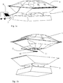
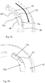
- FIG 1a is a schematic view of a bioreactor 1 in a rocking support structure 3.
- Figure 1b shows the same bioreactor system but in an exploded view.
- a sensor holding part 11 is provided in the bottom part of the bioreactor 1 .
- the sensor holding part holds an optical sensor on the inside of the bag. Details of this will be described further down in the description.
- An optical fibre 7 is provided to a position close to the position of the optical sensor but outside the bag with the help of an adaptor part 41 (described in detail below).
- a monitor 9 is also shown where the readings from the optical sensor can be monitored.
- a sensor holding part (also called an optical sensor holding device) is provided inside the bag.
- the sensor holding part is integrated with the bag by means of for example welding.
- An adaptor part holding the optical fibre is provided outside the bag.
- the sensor holding part comprises an optical sensor and first locking parts protruding out from the bag. These first locking parts are adapted to mate with second locking parts of the adaptor part such that the optical fibre in the adaptor part will be safely positioned to and can communicate with the sensor inside the bag.
- the locking parts provide a locking mechanism that holds the optical fibre in a stable position in relation to the sensor in all directions.
- the optical fibre is provided lying flat along the bottom of the bag, i.e. the optical fibre is not pointing towards the sensor in the bag.
- a mirror is provided in the adaptor part such that the light can be directed to the sensor when the adaptor part is positioned below the sensor.
- This is suitable because the support structure does not need to be adapted to the sensor attachment arrangement.
- this sensor attachment arrangement can be used on already existing systems without any adaptation.
- the bag can be freely moved together with the sensor and the sensor attachment arrangement. More description around the details of suitable embodiments of the invention is given below.
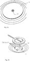
- Figure 2a is a view of a sensor holding part 11 (also called an optical sensor holding device 11) according to one embodiment of the invention.
- the sensor holding part 11 is in one embodiment positioned inside the bag and secured to the inner bag surface for example by means of welding. In another embodiment the sensor holding part is welded to the outside of the bag surface and a hole is provided in the bag surface around the sensor.
- the side adapted to face the interior of the bag is shown.
- the sensor holding part 11 is circular. This is suitable because a circular shape will give rise to less tension in the joint between the bag and the sensor holding part than would a shape with sharp edges. Furthermore, tension stress can cause creeping deformation of the sensor holding part.
- the circular geometry also reduces the risk for dimension changes due to different shrinkage in the molding process.
- the optical sensor 13 is provided in the centre of the sensor holding part 11 .
- the optical sensor is a dye as described in the background chapter and can also be called a sensor spot.
- the sensor holding part should be provided in a material that can be welded to the bag material.
- the bag is often made from polyethylene and in this embodiment also the sensor holding part is made from polyethylene.
- the material of the sensor 13 can not be attached directly to polyethylene and therefore the sensor has been provided on a small piece of another material to which the sensor can be attached and which is transparent.
- polycarbonate has been used. This is described in more detail below in relation to Figure 3 .
- Figure 2b shows the sensor holding part 11 of Figure 2a from the other side, i.e. from the side pointing out from the bag.
- four first locking means in the form of hooks 17a, 17b, 17c, 17d are provided protruding out from the sensor holding part.
- the hooks are provided on the circumference of a circle. The number of the hooks can also be 2, 3, 5 or even more.
- the first locking means 17a, b, c, d are adapted to protrude out from the bag when the sensor holding part is positioned inside the bag. At least one hole needs to be provided in the bag surface to let the first locking means 17 a, b, c, d through.
- a circular hole 23 as large as comprising all the first locking means 17a, b, c, d is provided in the bag.
- the sensor holding part is welded to the bag in order to prevent any leakage.
- the same circular hole is provided in the bag and furthermore a smaller circular piece of bag film is welded over the central part of the sensor holding part but inside the first locking means 17 a, b, c, d.
- This smaller circular piece of bag film will hereby cover the sensor in the middle of the sensor holding part. This could be suitable if there is any risk of leakage through the sensor attaching arrangement. This is described in more detail below in relation to Figure 3 .
- the sensor holding part needs then to be welded to the bag around all these four holes in order to prevent any leakage.
- the bag surface could be welded to the sensor holding part in one circle on the inside of the locking means and one circle outside the locking means.
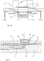
- Figure 3a is a cross section of a central part of the sensor attachment arrangement according to one embodiment of the invention.
- the sensor holding part 11 (also called the optical sensor holding device 11) comprises two parts.
- One bag attachment part 31 adapted to be welded to the bag and one sensor attachment part 33 where the sensor 13 is provided.
- the sensor attachment part 33 is made of a material to which the sensor 13 can be attached. This could be for example polycarbonate.
- the sensor attachment part 33 is pressed fit into an opening 34 in the bag attachment part 31.
- the bag attachment part 31 is made from a material that can be welded to the bag. Many bags are made from polyethylene and in this example also the bag attachment part 31 is made from polyethylene.
- the reason why the sensor 13 is not attached directly to the bag attachment part 31 is that the sensor 13 used in this example can not be attached to a material that also can be welded to the bag.
- the bag is made from polyethylene and therefore a suitable material for the sensor holding part is polyethylene. However the material of the sensor 13 used in this example can not be attached to polyethylene.
- the press fit of the sensor attachment part 33 in the opening 34 in the bag attachment part 31 disclosed here in relation to Figure 3a is a way to solve this problem.
- the sensor attachment part 33 should be slightly bigger than the opening 34.
- the sensor attachment part 33 is provided with a chamfer 35. This will give a radial pressure on the sensor attachment part 33 for the purpose of preventing leakage through the free press fit. This minimizes the risk of getting any liquid or dirt in the opening 37 below the sensor attachment part 33 where light will pass during the optical reading.
- a locking shoulder 38 is provided in the opening 34 in the bag attachment part 31.
- the locking shoulder 38 should keep the sensor attachment part 33 in place after having been forced to pass said locking shoulder 38 when pressed fitted into the opening 34.
- a circular piece of bag film 21 is also provided.
- This piece of bag film 21 is welded to the bag attachment part 31 around the central part of the bag attachment part 31 where the sensor 13 is provided. The purpose is to prevent any possible leakage outside the bag if such a leakage would occur through the press fit. However, if the press fit really is leakage free and reliable this circular piece of bag film 21 would not be necessary.
- an adaptor part 41 is also shown attached to the sensor holding part 11.
- An optical fibre 7 is positioned into the adaptor part 41.
- a combined mirror and lens 39 is provided in the adaptor part 41 connected to the optical fibre 7.
- the combined mirror and lens 39 directs and focuses the light from the optical fibre 7 onto the sensor spot 13.
- the sensor 13 is hereby illuminated via the fibre 7 and the excited fluorescent sensor 13 emits light that is monitored via the fibre 7.
- the light paths are shown by arrows.
- Figure 3b is a cross section view of a central part of the sensor attachment arrangement according to another embodiment of the invention before assembly.
- Figure 3c is a cross section of the embodiment shown in Figure 3b after assembly.
- a sensor holding part 11' (also called an optical sensor holding device 11') comprises two parts.
- One bag attachment part 31' adapted to be welded to the bag and one sensor attachment part 33' where the sensor 13 is provided.
- the sensor attachment part 33' is made of a material to which the sensor 13 can be attached. This could be for example polycarbonate.
- the sensor attachment part 33' is pressed fit into an opening 34' in the bag attachment part 31'.
- the bag attachment part 31' is made from a material that can be welded to the bag.
- the bag attachment part 31' is made from polyethylene.
- the reason why the sensor 13 is not attached directly to the bag attachment part 31' is that the sensor 13 used in this example can not be attached to a material that also can be welded to the bag.
- the bag is made from polyethylene and therefore a suitable material for the sensor holding part is polyethylene. However the material of the sensor 13 used in this example can not be attached to polyethylene.
- the press fit of the sensor attachment part 33' in the opening 34' in the bag attachment part 31' disclosed here in relation to Figures 3b and 3c is a way to solve this problem.
- the sensor attachment part 33' should be slightly bigger than the opening 34'.
- a force is applied around the opening 34' combined with a holding device 40 on the opposite side as shown by the force arrows in figure 3b when the sensor attachment part 33' should be pressed into the bag attachment part 31'.
- the entrance into the opening 34' will get larger (see also deformation arrows) and it will be easier to insert the sensor attachment part 33'.
- the sensor attachment part 33' is in place the force will be released and the sensor attachment part 33' will be positioned stably in the opening 34'.
- the sensor attachment part 33' is provided with a chamfer 35'. This will give a radial pressure on the sensor attachment part 33' for the purpose of preventing leakage through the free press fit.
- a hook 36 is provided on the sensor attachment part 33' which hook 36 will be pressed into the walls of the opening 34' of the bag attachment part 31' after insertion and assure a stable position of the sensor attachment part 33' in the bag attachment part 31'.
- Figure 3c is a cross section view of the sensor attaching arrangement of Figure 3b when assembled.
- an adaptor part 41 is also shown attached to the sensor holding part 11'.
- An optical fibre 7 is positioned into the adaptor part 41.
- a combined mirror and lens 39 is provided in the adaptor part 41 connected to the optical fibre 7.
- the combined mirror and lens 39 is provided right beneath the sensor in the sensor holding part 11'.
- the combined mirror and lens 39 directs and focuses the light from the optical fibre 7 onto the sensor spot 13.
- the sensor 13 is hereby illuminated via the fibre 7 and the excited fluorescent sensor 13 emits light that is monitored via the fibre 7.
- the light paths are shown by arrows.
- a circular piece of bag film 21 is also provided.
- This piece of bag film 21 is welded to the bag attachment part 31' around the central part of the bag attachment part 31' where the sensor 13 is provided. The purpose is to prevent any possible leakage outside the bag if such a leakage would occur through the press fit. However, if the press fit really is leakage free and reliable this circular piece of bag film 21 would not be necessary.
- Figure 4a shows an adaptor part 41 according to one embodiment of the invention.
- the adaptor part is provided in a material that is stiffer than the material pf the sensor holding part 11.
- a suitable material for the adaptor part is POM (Polyacetal plastic or Delrin plastic) or Peek (polyetereterketone plastic).
- POM Polyacetal plastic or Delrin plastic
- Peek polyetereterketone plastic
- the second locking means 43 a, b, c, d are in this embodiment provided as four tracks on the circumference of a circle.
- the dimensions are adapted for receiving the first locking means 17 a, b, c, d of the sensor holding part 11.
- each track 43 a, b, c, d comprises guiding surfaces leading the hooks into a locking position, i.e. after having rotated the adaptor part 41 in relation to the sensor holding part 11 (as shown in Figure 4b ) the first locking means 17 a, b, c, d have been guided into a second position within the tracks which is a locked position.
- Figure 4b shows the adaptor part of Figure 4a in a locked position.
- FIG. 5a is a closer view of the locking mechanism in one embodiment of the invention before locking.
- One first locking means 17a in the form of a hook is shown inserted into one second locking means 43a in the form of a track.
- a radial guiding surface 44 on the inner surface of the track 43a is provided for guiding a corresponding hook guiding surface 46 on the hook 17a into a radial locked position. Possibly the hook 17a is also pressed somewhat outwardly by the guiding surface 44.
- a locking bump 45 is shown in the track 43a.
- a gripping part 48 of the hook 17a will be caught by an inclined surface 42 of the track leading up to the locking bump 45 and the hook 17a will pass over the locking bump 45 when the adaptor part 41 is rotated in relation to the sensor holding part 11.
- the purpose of the locking bump 45 is to prevent the hook 17a from rotating back.
- Figure 5b is the same view as Figure 5a but in locked position, i.e. the adaptor part has been rotated to a locked position. Because all four locking parts provided in a circle are locked and because the locking mechanism is securing the adaptor part 41 in relation to the sensor holding part 11 in all directions the combined mirror and lens 39 of the adaptor part 41 can be kept steadily in relation to the sensor 13. Furthermore, this locking mechanism provides a very low tension stress on the sensor holding part. This is important because the sensor holding part is made from polyethylene and this material tends to be subjected to creepings/relaxation. Hereby the risk for creeping/relaxation in the sensor holding part is reduced to a minimum by the locking mechanism described here.
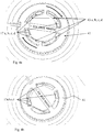
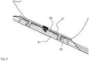
- Figure 6 is a cross section view showing the sensor holding part 11 being locked in the adaptor part 41 according to one embodiment of the invention.
- a contact surface 49 between the sensor holding part (possibly through the piece of bag film 21) and the adaptor part 41 can be seen.
- the gripping part 48 of the hook 17 is pressed by the track 43 into the locked position the sensor holding part and the adaptor part will come into contact at contact surface 49 (possibly through the piece of bag film 21).
- This contact is important because the distance between the sensor and the combined mirror and lens need to be kept constant and contact surfaces pressed towards each other. This will work well if the tension stress is kept at a minimum level and therefore reduces the risk for creeping of the sensor part.
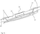
- Figure 7a shows another embodiment of a sensor holding part 51 where the sensor holding part is separated into an inner sensor holding part 53 and an outer locking part 55.
- Figure 7b is an exploded view of the sensor holding part of Figure 7a .
- the bag 65 needs not to be penetrated by the first locking means.
- the bioreactor bag surface can be kept intact. This could be good for preventing any contamination risk for the cell growth process.
- First locking means 57 are provided on the outer locking part 55.
- the inner sensor holding part 53 is welded to the bag surface and it comprises the sensor 59 in the middle facing the interior of the bag.
- the sensor attachment arrangement is suitably the same as described in relation to Figure 3 .
- the outer sensor holding part 55 is welded to the outside of the bag.
- the inner sensor holding part 53 and the outer locking part 55 will be welded together by bending the bag 65 according to Figure 7a and then an inner bag support ring 61 and an outer bag support ring 63 will be welded on top and on the bottom and secure the assembly.
- the adaptor part is suitably the same as described in relation to Figure 4a and 4b .
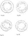
- Figures 8a-8d shows four different embodiments of adaptor parts according to the invention.
- both the first and second locking means of the invention can be designed in different forms.
- the result that should be achieved is a locking position where the two parts are kept together and are locked together in all directions.
- the geometry of the locking is important such that any creeping in the sensor holding part can be prevented.
- Figures 8a-8d shows the adaptor part already described in relation to Figures 4 and 5 .
- the locking is made in axial direction.
- the embodiments shown in Figures 8b, 8c and 8d provide a locking in radial direction.
- the sensors described above are optical sensors. These could be for example sensors for pH, DO, carbondioxide (CO 2 ), biomass, UV detection and IR detection.
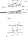
- Figure 9a and 9b show schematically another embodiment of the invention where the first and second locking parts are designed differently.
- a sensor holding part 91 is shown having four first locking means 93a, b, c, d in the form of plugs with larger heads 95a, b, c, d.
- An adaptor part 97 is also shown having four second locking means 99a, b, c, d in the form of receiving holes.
- one of the second locking means 99a is shown in cross section.
- the second locking means 99a comprises a retaining means 101a in the form of a section in the receiving hole having a smaller diameter than the rest of the hole and edges adapted for letting the larger head 95a of the first locking means 93a pass through the retaining means 101a when a force is applied from above.
- the edges of the retaining means 101 are further adapted for retaining the head 95a below the retaining means 101 when it has been pressed down there.
- a sensor is provided in the middle of the sensor holding part in the same way as described in for example relation to Figure 2a and b and an optical fibre is provided in the adaptor part in the same way as described in relation to Figure 3 .
- a support structure provided under the flexible bag need not be adapted in any way to the sensor attachment arrangement.
- the bag can be freely moved together with the sensor attachment arrangement and be used in any system.
- Another feature of the sensor attachment arrangement is that it is very flat and of low height. This is advantageous since it is important that its effect on the mixing of the culture in the bioreactor bag by protruding into the bag is limited. At the same time also small volumes of culture in the bag will cover the sensor.
- the different locking mechanisms described above and the mirror provided in the adaptor part are both important components in making the sensor attachment arrangement as flat as possible.
Claims (6)
- Bioreaktor, umfassend:eine optische Sensor-Haltevorrichtung (11; 11');einen flexiblen Beutel (1);und einen optischen Sensor (13), umfassend einen optischen Sensor-Spot (13), wobei die optische Sensor-Haltevorrichtung (11,11') umfasst- ein Beutelanbringungsteil (31; 31'), das an dem flexiblen Beutel (1) angeschweißt ist, wobei das Beutelanbringungsteil (31; 31') in den Beutel hinein eine Öffnung (34; 34') enthält;- ein optisches Sensoranbringungsteil (33; 33'), das aus einem transparenten Material hergestellt ist, das ein sich von dem Material des Beutelanbringungsteils (31,33) unterscheidendes Material ist, wobei der den optischen Sensor-Spot (13) umfassende optische Sensor an dem optischen Sensoranbringungsteil (33; 33') angebracht ist, wobei das optische Sensoranbringungsteil (33; 33') eine Presspassung in die Öffnung (34;34') ist, sodass das Sensoranbringungsteil in die Öffnung (34; 34') in dem Beutelanbringungsteil (31; 31') gezwungen werden kann, dass es geringfügig kleiner ist als das optische Sensoranbringungsteil (33; 33'), und so dass das optische Sensoranbringungsteil fest an Ort und Stelle gehalten wird und eine Leckage auf ein Minimum gehalten wird, wodurch der optische Sensor-Spot (13) in den Beutel hinein gerichtet ist, wenn das optische Sensoranbringungsteil in die Öffnung gepresst wird;der Bioreaktor weiter umfasst:einen Adapter (41) außen an dem Beutel und an dem optischen Sensoranbringungsteil (33,33') angebracht;einen Spiegel (39), der von dem Adapter (41) gehalten wird; undeine optische Faser (7), die zur optischen Kommunikation mit dem optischen Sensor (13) über den Spiegel (39) positioniert ist, wodurch die Faser im Wesentlichen senkrecht zu der Richtung optischer Kommunikation zu dem optischen Sensor über das transparente optische Sensoranbringungsteil (33; 33') angeordnet ist.
- Bioreaktor nach Anspruch 1, wobei das optische Sensoranbringungsteil (33; 33') angepasst ist, um den optischen Sensor im Inneren des flexiblen Beutels in direkter Kommunikation mit einer Kulturflüssigkeit im Inneren des Beutels bereitzustellen.
- Bioreaktor nach Anspruch 1 oder 2, wobei das Beutelanbringungsteil (31; 31') aus Polyethylen hergestellt wird und das optische Sensoranbringungsteil (33; 33') aus Polycarbonat hergestellt wird.
- Bioreaktor nach einem der vorstehenden Ansprüche, wobei das optische Sensoranbringungsteil (33; 33') mit einer Abschrägung (35; 35') bereitgestellt ist, wodurch dieses an dem optischen Sensoranbringungsteil (33; 33') für den Zweck des Verhinderns von Leckage durch die freie Presspassung einen radialen Druck liefern wird.
- Bioreaktor nach einem der vorstehenden Ansprüche, wobei eine verriegelnde Schulter (38) in der Öffnung (34) in dem Beutelanbringungsteil (31) bereitgestellt ist, wodurch die verriegelnde Schulter (38) das optische Sensoranbringungsteil (33) an Ort und Stelle hält, nachdem es gezwungen wurde, die verriegelnde Schulter (38) zu passieren, wenn es in die Öffnung (34) zur Presspassung gebracht worden ist.
- Bioreaktor nach einem der vorstehenden Ansprüche, weiter umfassend eine Bioreaktor-Stützstruktur (3).
Applications Claiming Priority (2)
| Application Number | Priority Date | Filing Date | Title |
|---|---|---|---|
| SE0950977 | 2009-12-17 | ||
| PCT/SE2010/050668 WO2011075036A1 (en) | 2009-12-17 | 2010-06-15 | Sensor attachment arrangement for flexible bags |
Publications (3)
| Publication Number | Publication Date |
|---|---|
| EP2513286A1 EP2513286A1 (de) | 2012-10-24 |
| EP2513286A4 EP2513286A4 (de) | 2013-11-06 |
| EP2513286B1 true EP2513286B1 (de) | 2019-08-28 |
Family
ID=44167553
Family Applications (1)
| Application Number | Title | Priority Date | Filing Date |
|---|---|---|---|
| EP10837965.2A Active EP2513286B1 (de) | 2009-12-17 | 2010-06-15 | Ein bioreaktor |
Country Status (7)
| Country | Link |
|---|---|
| US (1) | US9423351B2 (de) |
| EP (1) | EP2513286B1 (de) |
| JP (1) | JP5785188B2 (de) |
| CN (2) | CN102652174A (de) |
| CA (1) | CA2784231A1 (de) |
| IN (1) | IN2012DN04846A (de) |
| WO (1) | WO2011075036A1 (de) |
Families Citing this family (7)
| Publication number | Priority date | Publication date | Assignee | Title |
|---|---|---|---|---|
| WO2016124500A1 (en) * | 2015-02-04 | 2016-08-11 | Ge Healthcare Bio-Sciences Ab | Aseptically connectable sensor patch |
| US9868930B2 (en) * | 2015-04-24 | 2018-01-16 | Rosemount Analytical Inc. | pH sensor for single use equipment |
| DE102016006916B4 (de) * | 2016-06-06 | 2020-06-04 | Sartorius Stedim Biotech Gmbh | Sondenhalter und Verfahren zum Anordnen ener Sonde |
| US10584309B2 (en) | 2017-02-06 | 2020-03-10 | Rosemount Inc. | Pressure transducer for single-use containers |
| US20200255791A1 (en) * | 2019-02-08 | 2020-08-13 | Georgia Tech Research Corporation | Sensing Systems |
| US11371902B2 (en) | 2019-12-27 | 2022-06-28 | Rosemount Inc. | Process venting feature for use in sensor applications with a process fluid barrier |
| US20220298467A1 (en) * | 2021-03-17 | 2022-09-22 | Nirrin Technologies, Inc. | Rocking Bioreactor with Integrated Monitoring Probe System |
Family Cites Families (20)
| Publication number | Priority date | Publication date | Assignee | Title |
|---|---|---|---|---|
| US5810398A (en) * | 1992-10-02 | 1998-09-22 | Pall Corporation | Fluid delivery systems and methods and assemblies for making connections |
| US5393101A (en) * | 1992-10-02 | 1995-02-28 | Pall Corporation | Connector assembly |
| US5763279A (en) * | 1993-09-09 | 1998-06-09 | Synthecon, Inc. | Gas permeable bioreactor and method of use |
| US5686300A (en) | 1995-09-11 | 1997-11-11 | Becton Dickinson And Company | Fluorescence detector |
| US6815211B1 (en) * | 1998-08-04 | 2004-11-09 | Ntc Technology | Oxygen monitoring methods and apparatus (I) |
| US6086574A (en) * | 1997-11-21 | 2000-07-11 | Hyclone Laboratories, Inc. | Fluid delivery systems with diptube connector |
| US6338790B1 (en) | 1998-10-08 | 2002-01-15 | Therasense, Inc. | Small volume in vitro analyte sensor with diffusible or non-leachable redox mediator |
| CN1681709A (zh) * | 2002-09-19 | 2005-10-12 | Afp高级食品股份有限公司 | 用于在袋上产生熔接管的方法和装置以及因此制造的袋 |
| EP1701780B8 (de) * | 2004-01-07 | 2014-09-24 | Pall Technology UK limited | Behälter zur durchführung von biologischen prozessen enthaltend ein integriertes einblasrohr, sowie verfahren zu dessen herstellung |
| US20050163667A1 (en) * | 2004-01-26 | 2005-07-28 | Krause Richard J. | Single-use biobags with sendors: DO, pH, CO2 and temperature |
| AU2005240969A1 (en) * | 2004-04-27 | 2005-11-17 | Baxter Healthcare S.A. | Stirred-tank reactor system |
| US8304231B2 (en) * | 2004-08-16 | 2012-11-06 | Sartorius Stedim Switzerland Ag | Bioreactor |
| US7879599B2 (en) | 2005-04-22 | 2011-02-01 | Hyclone Laboratories, Inc. | Tube ports and related container systems |
| DE102006001623B4 (de) * | 2006-01-11 | 2009-05-07 | Sartorius Stedim Biotech Gmbh | Behälter und Verfahren zum Mischen von Medien |
| US7682822B2 (en) * | 2006-03-31 | 2010-03-23 | Aastrom Biosciences, Inc. | Ex vivo generated tissue system |
| US7824902B2 (en) * | 2006-11-03 | 2010-11-02 | Mark Selker | Optical interface for disposable bioreactors |
| JP4991352B2 (ja) * | 2007-03-02 | 2012-08-01 | 藤森工業株式会社 | 培養袋及び培養装置 |
| US8273825B2 (en) * | 2007-03-20 | 2012-09-25 | Sabic Innovative Plastics Ip B.V. | Polycarbonate/polyolefin based resin compositions and their production processes and uses |
| EP2155852B1 (de) * | 2007-06-15 | 2013-10-09 | Cellution Biotech B.V. | Verbesserter flexibler bioreaktor |
| JP5798568B2 (ja) * | 2009-12-17 | 2015-10-21 | ジーイー・ヘルスケア・バイオサイエンス・アクチボラグ | 可撓性バッグのセンサー取付け装置 |
-
2010
- 2010-06-15 CA CA2784231A patent/CA2784231A1/en not_active Abandoned
- 2010-06-15 CN CN2010800572763A patent/CN102652174A/zh active Pending
- 2010-06-15 EP EP10837965.2A patent/EP2513286B1/de active Active
- 2010-06-15 US US13/515,820 patent/US9423351B2/en active Active
- 2010-06-15 WO PCT/SE2010/050668 patent/WO2011075036A1/en active Application Filing
- 2010-06-15 CN CN201610587818.7A patent/CN106085852A/zh active Pending
- 2010-06-15 IN IN4846DEN2012 patent/IN2012DN04846A/en unknown
- 2010-06-15 JP JP2012544430A patent/JP5785188B2/ja active Active
Non-Patent Citations (1)
| Title |
|---|
| None * |
Also Published As
| Publication number | Publication date |
|---|---|
| IN2012DN04846A (de) | 2015-09-25 |
| CN102652174A (zh) | 2012-08-29 |
| WO2011075036A1 (en) | 2011-06-23 |
| US9423351B2 (en) | 2016-08-23 |
| CN106085852A (zh) | 2016-11-09 |
| JP2013514083A (ja) | 2013-04-25 |
| JP5785188B2 (ja) | 2015-09-24 |
| EP2513286A1 (de) | 2012-10-24 |
| CA2784231A1 (en) | 2011-06-23 |
| US20120291238A1 (en) | 2012-11-22 |
| EP2513286A4 (de) | 2013-11-06 |
Similar Documents
| Publication | Publication Date | Title |
|---|---|---|
| EP2513287B1 (de) | Sensorbefestigungsanordnung für flexible beutel | |
| EP2513286B1 (de) | Ein bioreaktor | |
| US11060055B2 (en) | Composite sensor assemblies for single use bioreactors | |
| US9267100B2 (en) | Composite sensor assemblies for single use bioreactors | |
| US8008065B2 (en) | Disposable bioreactor vessel port | |
| US20040086215A1 (en) | Sampling end for fiber optic probe | |
| US11940454B2 (en) | Optical reader for analyte testing | |
| JP2013514083A5 (de) | ||
| EP2812116B1 (de) | Mikrochip, mikrochipvorrichtung und herstellungsverfahren des mikrochips | |
| CN109642897B (zh) | 用于附接到瓶的适配器组件 | |
| WO2020132146A1 (en) | Optical analyte detection | |
| US9176060B2 (en) | Apparatus and methods to measure optical density | |
| JP2008191070A (ja) | サンプル容器及びサンプル容器ラック | |
| JP2016029347A (ja) | 試験管装着モジュールおよび試験管用モジュール | |
| US11280730B2 (en) | Bioprocess container having an optical measuring device | |
| US10989645B2 (en) | Non-invasive particle sensor using a multi-fiber connector | |
| JP2010066085A (ja) | 蛍光x線分析装置のセル及び蛍光x線分析装置 | |
| CN219417794U (zh) | 一种易连接的生物反应器柔性袋的转接件 | |
| US11827875B2 (en) | Method for manufacturing a composite sensor | |
| CN112892624A (zh) | 液体检测配套装置和检测设备 | |
| Pedersen et al. | Fiber Optic Biosensors: Potential Designs for Fermentation Sensing |
Legal Events
| Date | Code | Title | Description |
|---|---|---|---|
| PUAI | Public reference made under article 153(3) epc to a published international application that has entered the european phase |
Free format text: ORIGINAL CODE: 0009012 |
|
| 17P | Request for examination filed |
Effective date: 20120529 |
|
| AK | Designated contracting states |
Kind code of ref document: A1 Designated state(s): AL AT BE BG CH CY CZ DE DK EE ES FI FR GB GR HR HU IE IS IT LI LT LU LV MC MK MT NL NO PL PT RO SE SI SK SM TR |
|
| DAX | Request for extension of the european patent (deleted) | ||
| A4 | Supplementary search report drawn up and despatched |
Effective date: 20131008 |
|
| RIC1 | Information provided on ipc code assigned before grant |
Ipc: G01N 21/64 20060101ALI20131001BHEP Ipc: G01N 21/75 20060101ALI20131001BHEP Ipc: A61J 1/10 20060101ALI20131001BHEP Ipc: C12M 1/34 20060101AFI20131001BHEP |
|
| 17Q | First examination report despatched |
Effective date: 20131129 |
|
| STAA | Information on the status of an ep patent application or granted ep patent |
Free format text: STATUS: EXAMINATION IS IN PROGRESS |
|
| GRAP | Despatch of communication of intention to grant a patent |
Free format text: ORIGINAL CODE: EPIDOSNIGR1 |
|
| STAA | Information on the status of an ep patent application or granted ep patent |
Free format text: STATUS: GRANT OF PATENT IS INTENDED |
|
| INTG | Intention to grant announced |
Effective date: 20190318 |
|
| GRAS | Grant fee paid |
Free format text: ORIGINAL CODE: EPIDOSNIGR3 |
|
| GRAA | (expected) grant |
Free format text: ORIGINAL CODE: 0009210 |
|
| STAA | Information on the status of an ep patent application or granted ep patent |
Free format text: STATUS: THE PATENT HAS BEEN GRANTED |
|
| AK | Designated contracting states |
Kind code of ref document: B1 Designated state(s): AL AT BE BG CH CY CZ DE DK EE ES FI FR GB GR HR HU IE IS IT LI LT LU LV MC MK MT NL NO PL PT RO SE SI SK SM TR |
|
| REG | Reference to a national code |
Ref country code: GB Ref legal event code: FG4D |
|
| REG | Reference to a national code |
Ref country code: CH Ref legal event code: EP |
|
| REG | Reference to a national code |
Ref country code: AT Ref legal event code: REF Ref document number: 1172421 Country of ref document: AT Kind code of ref document: T Effective date: 20190915 |
|
| REG | Reference to a national code |
Ref country code: IE Ref legal event code: FG4D |
|
| REG | Reference to a national code |
Ref country code: DE Ref legal event code: R096 Ref document number: 602010060819 Country of ref document: DE |
|
| REG | Reference to a national code |
Ref country code: NL Ref legal event code: MP Effective date: 20190828 |
|
| REG | Reference to a national code |
Ref country code: LT Ref legal event code: MG4D |
|
| PG25 | Lapsed in a contracting state [announced via postgrant information from national office to epo] |
Ref country code: PT Free format text: LAPSE BECAUSE OF FAILURE TO SUBMIT A TRANSLATION OF THE DESCRIPTION OR TO PAY THE FEE WITHIN THE PRESCRIBED TIME-LIMIT Effective date: 20191230 Ref country code: HR Free format text: LAPSE BECAUSE OF FAILURE TO SUBMIT A TRANSLATION OF THE DESCRIPTION OR TO PAY THE FEE WITHIN THE PRESCRIBED TIME-LIMIT Effective date: 20190828 Ref country code: BG Free format text: LAPSE BECAUSE OF FAILURE TO SUBMIT A TRANSLATION OF THE DESCRIPTION OR TO PAY THE FEE WITHIN THE PRESCRIBED TIME-LIMIT Effective date: 20191128 Ref country code: NL Free format text: LAPSE BECAUSE OF FAILURE TO SUBMIT A TRANSLATION OF THE DESCRIPTION OR TO PAY THE FEE WITHIN THE PRESCRIBED TIME-LIMIT Effective date: 20190828 Ref country code: LT Free format text: LAPSE BECAUSE OF FAILURE TO SUBMIT A TRANSLATION OF THE DESCRIPTION OR TO PAY THE FEE WITHIN THE PRESCRIBED TIME-LIMIT Effective date: 20190828 Ref country code: SE Free format text: LAPSE BECAUSE OF FAILURE TO SUBMIT A TRANSLATION OF THE DESCRIPTION OR TO PAY THE FEE WITHIN THE PRESCRIBED TIME-LIMIT Effective date: 20190828 Ref country code: FI Free format text: LAPSE BECAUSE OF FAILURE TO SUBMIT A TRANSLATION OF THE DESCRIPTION OR TO PAY THE FEE WITHIN THE PRESCRIBED TIME-LIMIT Effective date: 20190828 Ref country code: NO Free format text: LAPSE BECAUSE OF FAILURE TO SUBMIT A TRANSLATION OF THE DESCRIPTION OR TO PAY THE FEE WITHIN THE PRESCRIBED TIME-LIMIT Effective date: 20191128 |
|
| PG25 | Lapsed in a contracting state [announced via postgrant information from national office to epo] |
Ref country code: IS Free format text: LAPSE BECAUSE OF FAILURE TO SUBMIT A TRANSLATION OF THE DESCRIPTION OR TO PAY THE FEE WITHIN THE PRESCRIBED TIME-LIMIT Effective date: 20191228 Ref country code: ES Free format text: LAPSE BECAUSE OF FAILURE TO SUBMIT A TRANSLATION OF THE DESCRIPTION OR TO PAY THE FEE WITHIN THE PRESCRIBED TIME-LIMIT Effective date: 20190828 Ref country code: GR Free format text: LAPSE BECAUSE OF FAILURE TO SUBMIT A TRANSLATION OF THE DESCRIPTION OR TO PAY THE FEE WITHIN THE PRESCRIBED TIME-LIMIT Effective date: 20191129 Ref country code: LV Free format text: LAPSE BECAUSE OF FAILURE TO SUBMIT A TRANSLATION OF THE DESCRIPTION OR TO PAY THE FEE WITHIN THE PRESCRIBED TIME-LIMIT Effective date: 20190828 Ref country code: AL Free format text: LAPSE BECAUSE OF FAILURE TO SUBMIT A TRANSLATION OF THE DESCRIPTION OR TO PAY THE FEE WITHIN THE PRESCRIBED TIME-LIMIT Effective date: 20190828 |
|
| REG | Reference to a national code |
Ref country code: AT Ref legal event code: MK05 Ref document number: 1172421 Country of ref document: AT Kind code of ref document: T Effective date: 20190828 |
|
| PG25 | Lapsed in a contracting state [announced via postgrant information from national office to epo] |
Ref country code: TR Free format text: LAPSE BECAUSE OF FAILURE TO SUBMIT A TRANSLATION OF THE DESCRIPTION OR TO PAY THE FEE WITHIN THE PRESCRIBED TIME-LIMIT Effective date: 20190828 |
|
| PG25 | Lapsed in a contracting state [announced via postgrant information from national office to epo] |
Ref country code: DK Free format text: LAPSE BECAUSE OF FAILURE TO SUBMIT A TRANSLATION OF THE DESCRIPTION OR TO PAY THE FEE WITHIN THE PRESCRIBED TIME-LIMIT Effective date: 20190828 Ref country code: PL Free format text: LAPSE BECAUSE OF FAILURE TO SUBMIT A TRANSLATION OF THE DESCRIPTION OR TO PAY THE FEE WITHIN THE PRESCRIBED TIME-LIMIT Effective date: 20190828 Ref country code: EE Free format text: LAPSE BECAUSE OF FAILURE TO SUBMIT A TRANSLATION OF THE DESCRIPTION OR TO PAY THE FEE WITHIN THE PRESCRIBED TIME-LIMIT Effective date: 20190828 Ref country code: AT Free format text: LAPSE BECAUSE OF FAILURE TO SUBMIT A TRANSLATION OF THE DESCRIPTION OR TO PAY THE FEE WITHIN THE PRESCRIBED TIME-LIMIT Effective date: 20190828 Ref country code: IT Free format text: LAPSE BECAUSE OF FAILURE TO SUBMIT A TRANSLATION OF THE DESCRIPTION OR TO PAY THE FEE WITHIN THE PRESCRIBED TIME-LIMIT Effective date: 20190828 Ref country code: RO Free format text: LAPSE BECAUSE OF FAILURE TO SUBMIT A TRANSLATION OF THE DESCRIPTION OR TO PAY THE FEE WITHIN THE PRESCRIBED TIME-LIMIT Effective date: 20190828 |
|
| PG25 | Lapsed in a contracting state [announced via postgrant information from national office to epo] |
Ref country code: SM Free format text: LAPSE BECAUSE OF FAILURE TO SUBMIT A TRANSLATION OF THE DESCRIPTION OR TO PAY THE FEE WITHIN THE PRESCRIBED TIME-LIMIT Effective date: 20190828 Ref country code: IS Free format text: LAPSE BECAUSE OF FAILURE TO SUBMIT A TRANSLATION OF THE DESCRIPTION OR TO PAY THE FEE WITHIN THE PRESCRIBED TIME-LIMIT Effective date: 20200224 Ref country code: SK Free format text: LAPSE BECAUSE OF FAILURE TO SUBMIT A TRANSLATION OF THE DESCRIPTION OR TO PAY THE FEE WITHIN THE PRESCRIBED TIME-LIMIT Effective date: 20190828 Ref country code: CZ Free format text: LAPSE BECAUSE OF FAILURE TO SUBMIT A TRANSLATION OF THE DESCRIPTION OR TO PAY THE FEE WITHIN THE PRESCRIBED TIME-LIMIT Effective date: 20190828 |
|
| REG | Reference to a national code |
Ref country code: DE Ref legal event code: R097 Ref document number: 602010060819 Country of ref document: DE |
|
| PLBE | No opposition filed within time limit |
Free format text: ORIGINAL CODE: 0009261 |
|
| STAA | Information on the status of an ep patent application or granted ep patent |
Free format text: STATUS: NO OPPOSITION FILED WITHIN TIME LIMIT |
|
| PG2D | Information on lapse in contracting state deleted |
Ref country code: IS |
|
| 26N | No opposition filed |
Effective date: 20200603 |
|
| PG25 | Lapsed in a contracting state [announced via postgrant information from national office to epo] |
Ref country code: SI Free format text: LAPSE BECAUSE OF FAILURE TO SUBMIT A TRANSLATION OF THE DESCRIPTION OR TO PAY THE FEE WITHIN THE PRESCRIBED TIME-LIMIT Effective date: 20190828 |
|
| REG | Reference to a national code |
Ref country code: DE Ref legal event code: R081 Ref document number: 602010060819 Country of ref document: DE Owner name: CYTIVA SWEDEN AB, SE Free format text: FORMER OWNER: GE HEALTHCARE BIO-SCIENCES AB, UPPSALA, SE |
|
| PG25 | Lapsed in a contracting state [announced via postgrant information from national office to epo] |
Ref country code: MC Free format text: LAPSE BECAUSE OF FAILURE TO SUBMIT A TRANSLATION OF THE DESCRIPTION OR TO PAY THE FEE WITHIN THE PRESCRIBED TIME-LIMIT Effective date: 20190828 |
|
| REG | Reference to a national code |
Ref country code: CH Ref legal event code: PL |
|
| PG25 | Lapsed in a contracting state [announced via postgrant information from national office to epo] |
Ref country code: LU Free format text: LAPSE BECAUSE OF NON-PAYMENT OF DUE FEES Effective date: 20200615 |
|
| REG | Reference to a national code |
Ref country code: BE Ref legal event code: MM Effective date: 20200630 |
|
| PG25 | Lapsed in a contracting state [announced via postgrant information from national office to epo] |
Ref country code: IE Free format text: LAPSE BECAUSE OF NON-PAYMENT OF DUE FEES Effective date: 20200615 Ref country code: LI Free format text: LAPSE BECAUSE OF NON-PAYMENT OF DUE FEES Effective date: 20200630 Ref country code: CH Free format text: LAPSE BECAUSE OF NON-PAYMENT OF DUE FEES Effective date: 20200630 |
|
| PG25 | Lapsed in a contracting state [announced via postgrant information from national office to epo] |
Ref country code: BE Free format text: LAPSE BECAUSE OF NON-PAYMENT OF DUE FEES Effective date: 20200630 |
|
| PG25 | Lapsed in a contracting state [announced via postgrant information from national office to epo] |
Ref country code: MT Free format text: LAPSE BECAUSE OF FAILURE TO SUBMIT A TRANSLATION OF THE DESCRIPTION OR TO PAY THE FEE WITHIN THE PRESCRIBED TIME-LIMIT Effective date: 20190828 Ref country code: CY Free format text: LAPSE BECAUSE OF FAILURE TO SUBMIT A TRANSLATION OF THE DESCRIPTION OR TO PAY THE FEE WITHIN THE PRESCRIBED TIME-LIMIT Effective date: 20190828 |
|
| PG25 | Lapsed in a contracting state [announced via postgrant information from national office to epo] |
Ref country code: MK Free format text: LAPSE BECAUSE OF FAILURE TO SUBMIT A TRANSLATION OF THE DESCRIPTION OR TO PAY THE FEE WITHIN THE PRESCRIBED TIME-LIMIT Effective date: 20190828 |
|
| REG | Reference to a national code |
Ref country code: FR Ref legal event code: PLFP Year of fee payment: 14 |
|
| P01 | Opt-out of the competence of the unified patent court (upc) registered |
Effective date: 20230526 |
|
| PGFP | Annual fee paid to national office [announced via postgrant information from national office to epo] |
Ref country code: FR Payment date: 20230411 Year of fee payment: 14 Ref country code: DE Payment date: 20230418 Year of fee payment: 14 |
|
| PGFP | Annual fee paid to national office [announced via postgrant information from national office to epo] |
Ref country code: GB Payment date: 20230427 Year of fee payment: 14 |