EP2512784B1 - Mechanismus und verfahren zur stabilisierung einer verbundschicht - Google Patents
Mechanismus und verfahren zur stabilisierung einer verbundschicht Download PDFInfo
- Publication number
- EP2512784B1 EP2512784B1 EP20100782107 EP10782107A EP2512784B1 EP 2512784 B1 EP2512784 B1 EP 2512784B1 EP 20100782107 EP20100782107 EP 20100782107 EP 10782107 A EP10782107 A EP 10782107A EP 2512784 B1 EP2512784 B1 EP 2512784B1
- Authority
- EP
- European Patent Office
- Prior art keywords
- grip strip
- core
- composite structure
- laminate
- plies
- Prior art date
- Legal status (The legal status is an assumption and is not a legal conclusion. Google has not performed a legal analysis and makes no representation as to the accuracy of the status listed.)
- Active
Links
- 239000002131 composite material Substances 0.000 title claims abstract description 135
- 230000007246 mechanism Effects 0.000 title claims abstract description 80
- 230000000087 stabilizing effect Effects 0.000 title claims abstract description 72
- 238000000034 method Methods 0.000 title claims description 53
- 238000007789 sealing Methods 0.000 claims description 6
- 239000011162 core material Substances 0.000 description 129
- 239000000463 material Substances 0.000 description 21
- 238000004519 manufacturing process Methods 0.000 description 16
- 239000011152 fibreglass Substances 0.000 description 8
- 239000000853 adhesive Substances 0.000 description 6
- 230000001070 adhesive effect Effects 0.000 description 6
- 238000010586 diagram Methods 0.000 description 6
- 230000008901 benefit Effects 0.000 description 4
- 239000010410 layer Substances 0.000 description 4
- 230000008569 process Effects 0.000 description 4
- 238000010276 construction Methods 0.000 description 3
- 230000002093 peripheral effect Effects 0.000 description 3
- 230000004044 response Effects 0.000 description 3
- 239000000565 sealant Substances 0.000 description 3
- XAGFODPZIPBFFR-UHFFFAOYSA-N aluminium Chemical compound [Al] XAGFODPZIPBFFR-UHFFFAOYSA-N 0.000 description 2
- 229910052782 aluminium Inorganic materials 0.000 description 2
- 238000007596 consolidation process Methods 0.000 description 2
- 238000007689 inspection Methods 0.000 description 2
- 238000012423 maintenance Methods 0.000 description 2
- 239000007769 metal material Substances 0.000 description 2
- 230000004048 modification Effects 0.000 description 2
- 238000012986 modification Methods 0.000 description 2
- 239000003381 stabilizer Substances 0.000 description 2
- 239000012790 adhesive layer Substances 0.000 description 1
- 238000013459 approach Methods 0.000 description 1
- 239000004760 aramid Substances 0.000 description 1
- 229920003235 aromatic polyamide Polymers 0.000 description 1
- -1 but not limited to Substances 0.000 description 1
- 238000005056 compaction Methods 0.000 description 1
- 238000013461 design Methods 0.000 description 1
- 230000001066 destructive effect Effects 0.000 description 1
- 230000007613 environmental effect Effects 0.000 description 1
- 230000002349 favourable effect Effects 0.000 description 1
- 239000000835 fiber Substances 0.000 description 1
- 238000010438 heat treatment Methods 0.000 description 1
- 230000010354 integration Effects 0.000 description 1
- 239000000203 mixture Substances 0.000 description 1
- 230000008520 organization Effects 0.000 description 1
- 238000002360 preparation method Methods 0.000 description 1
- 238000009419 refurbishment Methods 0.000 description 1
- 239000011347 resin Substances 0.000 description 1
- 229920005989 resin Polymers 0.000 description 1
- 230000000452 restraining effect Effects 0.000 description 1
- 229910001220 stainless steel Inorganic materials 0.000 description 1
- 239000010935 stainless steel Substances 0.000 description 1
- 238000009966 trimming Methods 0.000 description 1
- 239000003039 volatile agent Substances 0.000 description 1
- 239000002759 woven fabric Substances 0.000 description 1
Images


Classifications
-
- B—PERFORMING OPERATIONS; TRANSPORTING
- B32—LAYERED PRODUCTS
- B32B—LAYERED PRODUCTS, i.e. PRODUCTS BUILT-UP OF STRATA OF FLAT OR NON-FLAT, e.g. CELLULAR OR HONEYCOMB, FORM
- B32B37/00—Methods or apparatus for laminating, e.g. by curing or by ultrasonic bonding
- B32B37/10—Methods or apparatus for laminating, e.g. by curing or by ultrasonic bonding characterised by the pressing technique, e.g. using action of vacuum or fluid pressure
-
- B—PERFORMING OPERATIONS; TRANSPORTING
- B29—WORKING OF PLASTICS; WORKING OF SUBSTANCES IN A PLASTIC STATE IN GENERAL
- B29C—SHAPING OR JOINING OF PLASTICS; SHAPING OF MATERIAL IN A PLASTIC STATE, NOT OTHERWISE PROVIDED FOR; AFTER-TREATMENT OF THE SHAPED PRODUCTS, e.g. REPAIRING
- B29C70/00—Shaping composites, i.e. plastics material comprising reinforcements, fillers or preformed parts, e.g. inserts
- B29C70/04—Shaping composites, i.e. plastics material comprising reinforcements, fillers or preformed parts, e.g. inserts comprising reinforcements only, e.g. self-reinforcing plastics
- B29C70/28—Shaping operations therefor
- B29C70/40—Shaping or impregnating by compression not applied
- B29C70/42—Shaping or impregnating by compression not applied for producing articles of definite length, i.e. discrete articles
- B29C70/44—Shaping or impregnating by compression not applied for producing articles of definite length, i.e. discrete articles using isostatic pressure, e.g. pressure difference-moulding, vacuum bag-moulding, autoclave-moulding or expanding rubber-moulding
-
- B—PERFORMING OPERATIONS; TRANSPORTING
- B29—WORKING OF PLASTICS; WORKING OF SUBSTANCES IN A PLASTIC STATE IN GENERAL
- B29C—SHAPING OR JOINING OF PLASTICS; SHAPING OF MATERIAL IN A PLASTIC STATE, NOT OTHERWISE PROVIDED FOR; AFTER-TREATMENT OF THE SHAPED PRODUCTS, e.g. REPAIRING
- B29C70/00—Shaping composites, i.e. plastics material comprising reinforcements, fillers or preformed parts, e.g. inserts
- B29C70/04—Shaping composites, i.e. plastics material comprising reinforcements, fillers or preformed parts, e.g. inserts comprising reinforcements only, e.g. self-reinforcing plastics
- B29C70/28—Shaping operations therefor
- B29C70/54—Component parts, details or accessories; Auxiliary operations, e.g. feeding or storage of prepregs or SMC after impregnation or during ageing
- B29C70/541—Positioning reinforcements in a mould, e.g. using clamping means for the reinforcement
-
- B—PERFORMING OPERATIONS; TRANSPORTING
- B29—WORKING OF PLASTICS; WORKING OF SUBSTANCES IN A PLASTIC STATE IN GENERAL
- B29C—SHAPING OR JOINING OF PLASTICS; SHAPING OF MATERIAL IN A PLASTIC STATE, NOT OTHERWISE PROVIDED FOR; AFTER-TREATMENT OF THE SHAPED PRODUCTS, e.g. REPAIRING
- B29C70/00—Shaping composites, i.e. plastics material comprising reinforcements, fillers or preformed parts, e.g. inserts
- B29C70/04—Shaping composites, i.e. plastics material comprising reinforcements, fillers or preformed parts, e.g. inserts comprising reinforcements only, e.g. self-reinforcing plastics
- B29C70/28—Shaping operations therefor
- B29C70/54—Component parts, details or accessories; Auxiliary operations, e.g. feeding or storage of prepregs or SMC after impregnation or during ageing
- B29C70/543—Fixing the position or configuration of fibrous reinforcements before or during moulding
-
- B—PERFORMING OPERATIONS; TRANSPORTING
- B29—WORKING OF PLASTICS; WORKING OF SUBSTANCES IN A PLASTIC STATE IN GENERAL
- B29D—PRODUCING PARTICULAR ARTICLES FROM PLASTICS OR FROM SUBSTANCES IN A PLASTIC STATE
- B29D99/00—Subject matter not provided for in other groups of this subclass
- B29D99/001—Producing wall or panel-like structures, e.g. for hulls, fuselages, or buildings
- B29D99/0021—Producing wall or panel-like structures, e.g. for hulls, fuselages, or buildings provided with plain or filled structures, e.g. cores, placed between two or more plates or sheets, e.g. in a matrix
-
- Y—GENERAL TAGGING OF NEW TECHNOLOGICAL DEVELOPMENTS; GENERAL TAGGING OF CROSS-SECTIONAL TECHNOLOGIES SPANNING OVER SEVERAL SECTIONS OF THE IPC; TECHNICAL SUBJECTS COVERED BY FORMER USPC CROSS-REFERENCE ART COLLECTIONS [XRACs] AND DIGESTS
- Y02—TECHNOLOGIES OR APPLICATIONS FOR MITIGATION OR ADAPTATION AGAINST CLIMATE CHANGE
- Y02T—CLIMATE CHANGE MITIGATION TECHNOLOGIES RELATED TO TRANSPORTATION
- Y02T50/00—Aeronautics or air transport
- Y02T50/40—Weight reduction
-
- Y—GENERAL TAGGING OF NEW TECHNOLOGICAL DEVELOPMENTS; GENERAL TAGGING OF CROSS-SECTIONAL TECHNOLOGIES SPANNING OVER SEVERAL SECTIONS OF THE IPC; TECHNICAL SUBJECTS COVERED BY FORMER USPC CROSS-REFERENCE ART COLLECTIONS [XRACs] AND DIGESTS
- Y10—TECHNICAL SUBJECTS COVERED BY FORMER USPC
- Y10T—TECHNICAL SUBJECTS COVERED BY FORMER US CLASSIFICATION
- Y10T156/00—Adhesive bonding and miscellaneous chemical manufacture
- Y10T156/10—Methods of surface bonding and/or assembly therefor
- Y10T156/1089—Methods of surface bonding and/or assembly therefor of discrete laminae to single face of additional lamina
- Y10T156/1092—All laminae planar and face to face
-
- Y—GENERAL TAGGING OF NEW TECHNOLOGICAL DEVELOPMENTS; GENERAL TAGGING OF CROSS-SECTIONAL TECHNOLOGIES SPANNING OVER SEVERAL SECTIONS OF THE IPC; TECHNICAL SUBJECTS COVERED BY FORMER USPC CROSS-REFERENCE ART COLLECTIONS [XRACs] AND DIGESTS
- Y10—TECHNICAL SUBJECTS COVERED BY FORMER USPC
- Y10T—TECHNICAL SUBJECTS COVERED BY FORMER US CLASSIFICATION
- Y10T428/00—Stock material or miscellaneous articles
- Y10T428/31504—Composite [nonstructural laminate]
Definitions
- the present disclosure relates generally to composite construction and, more particularly, to a system and method of stabilizing composite plies against movement relative to one another.
- Sandwich structures constructed of honeycomb core or other lightweight core materials provide several advantages over other composite structural arrangements.
- Sandwich structures typically include the core material bounded on opposing sides of the core by face sheets or laminates comprised of one or more plies of composite material. Due to the relatively light weight of the core, the combination of the core and laminates on opposing sides of the core results in a relatively high stiffness-to-weight ratio as compared to composite structures comprised of laminated plies.
- composite sandwich structures have relatively high strength-to-weight ratios due to the relatively low density of the core material. Certain structures such as, without limitation, wing flaps and/or doors of a commercial airliner may benefit from a composite sandwich construction due to the favorable stiffness characteristics and light weight.
- a composite structure During the fabrication of a composite structure, pressure and heat are typically applied to a layup of composite materials that make up the structure in order to cure and bond the composite materials.
- An autoclave may be employed as a means for applying heat and pressure to the composite material layup such as a composite sandwich structure layup.
- the geometry and size of the flap may present challenges regarding the curing and bonding of the composite materials to the core.
- the wing flap of a commercial airliner may have relatively large core thicknesses (e.g., six inches or larger) with a trend toward increasing core thicknesses in response to ongoing efforts to minimize weight in composite structures.
- the wing flap may also include one or more chamfers for tapering the core thickness such as along a direction toward the perimeter of the flap.
- the chamfer angle may exceed 10 degrees and may be as large as 20 degrees or greater depending upon the flap geometry.
- the pressure exerted by the autoclave e.g., approximately 45 psi
- a relatively large side load e.g., up to 4,000 pounds
- the relatively large side load may result in movement or slippage of the plies of the upper and lower laminates relative to one another along a direction from the flap perimeter toward the core chamfer.
- the heating of the plies between which the core is sandwiched may reduce the viscosity of the resin that is in contact with the core and which may reduce friction and further facilitate ply slippage.
- the slippage of the plies relative to one another may result in movement of the core causing the core to be compacted or crushed in response to the ply movement.
- Prior art attempts to prevent core crush include the application of film adhesive and a fiberglass sheet around the border of the composite panel in an effort to stabilize the core from movement during the application of autoclave pressure. Unfortunately, the fiberglass sheet extends across the surface of the core resulting in additional weight to the structure.
- Other attempts to prevent core crush include the application of tie down straps along the perimeter of the composite layup.
- the tie down straps may comprise fiberglass straps that may be secured to the tool and extended over and adhered to the uppermost ply of the composite layup. However, such tie down straps may be ineffective against the relatively large side forces exerted on chamfers of large surface area during the application of autoclave pressure.
- Another approach to preventing ply slippage in composite structures is to septumize or split the core along a horizontal plane at an approximate mid-height of the core.
- Layers of fiberglass and adhesives may be installed between upper and lower portions of the split core in an attempt to stabilize the core against movement.
- the addition of the fiberglass and adhesive layers may eliminate the ability to perform a non-destructive inspection of the composite panel using ultrasonic inspection techniques due to blockage of the ultrasonic signal by the fiberglass layer.
- the addition of the fiberglass sheet and adhesive may add to the weight of the composite structure.
- Document WO 96/22878 A1 shows a method for making a honeycomb core composite article including forming a honeycomb core and a precured composite skin having a core edge and a restraint edge, respectively.
- the precured composite skin is placed in combination with a rigid mold member having a mold surface and the honeycomb core is mated with the precured composite skin to form a mated subassembly.
- An uncured composite skin is laid over the mated subassembly such that a peripheral portion of the uncured composite skin extends beyond the restraint edge by a distance X and such that the peripheral portion is in superposed abutting engagement with the mold surface.
- honeycomb core, the precured composite skin and the uncured composite skin define a composite lay-up over which a vacuum bag is disposed.
- the resultant mold cavity is evacuated to urge the vacuum bag against the uncured composite skin thereby effecting engagement of the peripheral portion with the restraint edge and the mold surface.
- the composite lay-up is then cured to form the completed honeycomb core composite article.
- the method produces a honeycomb core composite article wherein the honeycomb core thereof is accurately located and substantially distortion-free.
- a stabilizing mechanism for resisting relative movement of upper and lower laminates of a composite structure having a core.
- the upper and lower laminates may be mounted to the core.
- the stabilizing mechanism may comprise a lower grip strip mounted to the tool and may have an outer surface and may include at least one engagement feature for engaging at least one of the upper and lower laminates.
- the stabilizing mechanism may include at least one upper grip strip which may have opposing outer surfaces wherein each one of the outer surfaces may include at least one of the engagement features for engaging the lower grip strip and at least one of the upper and lower laminates.
- a stabilizing mechanism for resisting relative movement of the upper and lower laminates which may be mounted to a chamfered core of a composite structure to prevent core crush of the chamfered core.
- the composite structure may be mounted on a tool. Core crush may occur under the application of autoclave force to the chamfer formed in the core.
- the composite structure may include upper and lower laminates respectively mounted to upper and lower surfaces of the core.
- the upper and lower laminates may be respectively comprised of upper and lower plies.
- the composite structure may have a perimeter that may include a trim line defining a trim margin.
- the stabilizing mechanism may comprise a lower grip strip bonded to the tool within the trim margin and may include a generally elongate metallic sheet member having inner and outer surfaces.
- the stabilizing mechanism may include a plurality of protrusions extending outwardly from the outer surface. The protrusions from the lower grip strip may engage at least two of the plies for preventing movement relative to the lower grip strip.
- the stabilizing mechanism may include at least one upper grip strip that may be positioned in substantial alignment with the lower grip strip and may comprise a pair of the sheet members bonded at the inner surfaces in back-to-back arrangement. Each one of the sheet members may have a plurality of the protrusions extending outwardly from the respective outer surfaces.
- the protrusions from the upper grip strip may engage the lower grip strip for preventing movement relative thereto and may engage at least two of the plies on opposing sides of the upper grip strip for preventing movement of the plies relative to the upper grip strip.
- At least one tie strap may be mounted to the tool and may overlap a portion of the upper grip strip.
- a bagging film may seal the composite structure to the tool for applying compressive force on the upper and lower laminates to increase engagement with the upper and lower grip strips.
- the present disclosure further includes a system for resisting relative movement of upper and lower laminates mounted to a chamfered core of a composite structure to reduce core crush of the chamfered core.
- the system may comprise a tool for receiving the composite structure and a stabilizing mechanism.
- the stabilizing mechanism may include a lower grip strip mounted to the tool and which may have an outer surface that includes at least one engagement feature for engaging at least one of the upper and lower laminates.
- the stabilizing mechanism may include at least one upper grip strip which may have opposing outer surfaces each of which may include at least one engagement feature for engaging the lower grip strip and at least one of the upper and lower laminates.
- the system may include a force mechanism for applying a compressive force to the upper laminate for increasing the engagement of the upper and lower laminates to the upper and lower grip strips.
- the method may comprise the steps of mounting a lower grip strip to a tool and laying up a lower laminate on the tool such that the lower laminate engages a portion of the lower grip strip.
- the method may further comprise placing a core on the lower laminate, positioning an upper grip strip such that a portion thereof engages the lower grip strip, and laying up an upper laminate over the core such that a portion of the upper laminate engages the upper grip strip.
- a method of resisting relative movement of upper and lower laminates mounted to a chamfered core of a composite structure to reduce core crush in the chamfered core under the application of autoclave force to the chamfer may be mounted on a tool and may have a perimeter that may include a trim line defining a trim margin.
- the core may have at least one chamfer.
- the method may comprise the steps of bonding a lower grip strip to the tool within the trim margin.
- the lower grip strip may have protrusions extending outwardly from an outer surface thereof.
- the method may include laying up lower plies of the lower laminate onto the tool such that at least two of the lower plies engage a portion of the lower grip strip.
- the lower plies may be terminated in staggered relation to one another on the lower grip strip.
- the method may include positioning the core over the lower laminate within the trim line, positioning at least one upper grip strip in substantial alignment with the lower grip strip and engaging the upper grip strip to a portion of the lower grip strip.
- the method may include laying up upper plies of an upper laminate over the core such that at least two of the upper plies overlap and engage a portion of the upper grip strip.
- the upper plies may terminate in staggered relation to one another on the upper grip strip.
- the method may also include mounting at least one tie strap to the tool and extending the tie strap over at least a portion of the upper grip strip and along a length thereof. A compressive force may be applied to the composite structure to increase engagement of the upper and lower laminates to the upper and lower grip strips.
- a stabilizing mechanism for resisting relative movement of upper and lower laminates of a composite structure having a core
- the stabilizing mechanism including a lower grip strip mounted to a tool and having an outer surface including at least one engagement feature for engaging at least one of the upper and lower laminates; and at least one upper grip strip having opposing outer surfaces, each one of the outer surfaces including at least one of the engagement features for engaging the lower grip strip and at least one of the upper and lower laminates.
- the engagement feature may comprise a plurality of protrusions.
- the lower grip strip may comprise a sheet member having inner and outer surfaces and the protrusions extending from the outer surface.
- the upper grip strip may comprise a pair of the sheet members connected in back-to-back arrangement at the inner surfaces such that the protrusions extend outwardly from the respective outer surfaces.
- the composite structure may include a perimeter having a trim line defining a trim margin of the composite structure; and the upper and lower grip strips being located within the trim margin.
- the upper and lower grip strips may be substantially aligned with one another.
- the stabilizing mechanism may further include at least one tie strap mounted to the tool and overlapping a portion of the upper grip strip.
- the stabilizing mechanism may further include a bagging film sealing the composite structure to the tool for applying compressive force on the upper and lower laminates to increase engagement with the upper and lower grip strips.
- a stabilizing mechanism for resisting relative movement of upper and lower laminates mounted to a chamfered core of a composite structure to prevent core crush of the chamfered core under the application of autoclave force to the chamfered core, the upper and lower laminates being respectively mounted to upper and lower surfaces of the core, the upper and lower laminates being respectively comprised of upper and lower plies, the composite structure having a perimeter including a trim line defining a trim margin, the stabilizing mechanism including a lower grip strip bonded to the tool within the trim margin and including a generally elongate metallic sheet member having inner and outer surfaces and including a plurality of protrusions extending outwardly from the outer surface, the protrusions from the lower grip strip engaging at least two of the plies for preventing movement relative to the lower grip strip; at least one upper grip strip in substantial alignment with the lower grip strip and including a pair of the sheet members bonded at the inner surfaces in back-to-back arrangement and each having a plurality of the protrusion
- a system for resisting relative movement of upper and lower laminates mounted to a chamfered core of a composite structure to reduce core crush of the chamfered core including a tool for receiving the composite structure a stabilizing mechanism, including a lower grip strip mounted to the tool and having an outer surface including at least one engagement feature for engaging at least one of the upper and lower laminates; and at least one upper grip strip having opposing outer surfaces each including at least one engagement feature for engaging the lower grip strip and at least one of the upper and lower laminates; and a force mechanism for applying a compressive force to the upper laminate for increasing the engagement of the upper and lower laminates to the upper and lower grip strips.
- the force mechanism may comprise at least one of the following: a bagging film for sealing the composite structure to the tool and drawing a vacuum thereon; and autoclave pressure applied to the composite structure.
- the engagement feature may comprise a plurality of protrusions.
- the lower grip strip may comprise a sheet member having inner and outer surfaces, the protrusions extending from the outer surface.
- the upper grip strip may comprise a pair of the sheet members connected in back-to-back arrangement at the inner surfaces such that the protrusions extend outwardly from the respective outer surfaces.
- an embodiment of a method of resisting relative movement of upper and lower laminates mounted to a chamfered core of a composite structure to reduce core crush in the chamfered core including the steps of mounting a lower grip strip to a tool; laying up a lower laminate on the tool such that the lower laminate engages a portion of the lower grip strip; placing a core on the lower laminate; positioning an upper grip strip such that a portion thereof engages the lower grip strip; and laying up an upper laminate over the core such that a portion of the upper laminate engages the upper grip strip.
- the step of laying up the upper laminate over the core may comprise: laying up the upper laminate over the core such that a portion thereof overlaps the lower laminate and engages the upper grip strip.
- the step of laying up the upper laminate may include: terminating at least two of the upper plies in staggered relation to one another.
- the method further may include the step of: laying up the upper and lower laminates such that at least one of the upper and lower plies engages both of the upper and lower grip strips.
- the step of mounting the lower grip strip to the tool may include: positioning the lower grip strip within the trim margin along the perimeter.
- the method may further include the step of: forming the lower grip strip from a sheet member having inner and outer surfaces and protrusions extending from the outer surface.
- the method may further include the step of: forming the upper grip strip by bonding a pair of the sheet members in back-to-back arrangement at the inner surfaces thereof such that the protrusions extend outwardly from the respective outer surfaces.
- the method may further include the step of: applying a compressive force to the composite structure to increase engagement of the upper and lower laminates to the upper and lower grip strips.
- the step of applying the compressive force may comprise at least one of the following: drawing a vacuum on a bagging film sealing the composite structure to the tool; and applying autoclave pressure to the composite structure.
- a composite structure produced according to the embodiment of the method of resisting relative movement of upper and lower laminates mounted to a chamfered core of a composite structure to reduce core crush in the chamfered core.
- FIG. 1 shown in Figure 1 is a plan view of an aircraft 120 as an example of one of a variety of applications where a stabilizing mechanism 72 ( Figs. 2-3 ) may be implemented for preventing relative ply 32, 34 ( Fig. 2 ) movement during fabrication of a composite structure 10.
- the aircraft 120 includes a pair of wings 124 extending outwardly from a fuselage 122 from inboard 14 to outboard 16 and having propulsion units 134.
- the aircraft 120 may include a tail section 128 having a horizontal stabilizer 130, a vertical stabilizer 132, and/or other control surfaces 126.
- the aircraft 120 may include other components which may advantageously incorporate the use of the stabilizing mechanism 72 ( Figs. 2-3 ) as disclosed herein during the fabrication of the composite structures 10.
- the aircraft 120 may include one or more wing flaps 136 which may be formed as a composite structure 10 benefiting from the stabilizing mechanism 72 (Figs. 2-3 ) in preventing ply 32, 34 ( Fig. 2 ) movement and core 20 ( Fig. 2 ) crush during the fabrication process.
- the stabilizing mechanism 72 as disclosed herein is described with regard to a wing flap 136 as may be used in an aircraft 120, the stabilizing mechanism 72 may be implemented in the fabrication of a composite structure 10 for any vehicular or non-vehicular application and for use in any industry including, without limitation, the marine and automotive industries.
- the stabilizing mechanism 72 and method disclosed herein is not limited for use in sandwich panels having a lightweight open cell core such as honeycomb core 20, but may include the fabrication of any composite structure 10 comprised of layered plies 32, 34 ( Fig. 2 ) wherein ply movement may occur.
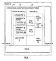
- the composite structure 10 configured as a wing flap 136 and mounted on a tool 50 as may be used for the layup and preparation of the composite structure 10 prior to consolidating and/or curing of the composite structure 10.
- the composite structure 10 may be configured in a variety of alternative shapes, sizes and configurations without limitation and which may benefit from the stabilizing mechanism 72 as disclosed herein.
- the tool 50 may include tooling fixtures 52 for restraining the composite structure 10 during the fabrication process.
- the composite structure 10 may be laid on a tool surface 54 of the tool 50 as illustrated in Figure 2 .
- the tool 50 may also be transportable such that the composite structure 10 may be moved from a layup facility to an autoclave facility for the application of heat and/or pressure during cure.
- the composite structure 10 may include upper and lower laminates 28, 30 between which the core 20 may be sandwiched.
- the composite structure 10 may include a perimeter 48 along which the stabilizing mechanism 72 may be located.
- the lower laminate 30 may be comprised of lower plies 34 upon which the core 20 may be mounted.
- the upper laminate 28 may be comprised of upper plies 32 which may be laid over the core 20 and which may also overlap the lower laminate 30 at the edge of the core 20 to form a skin member 12.
- the core 20 may be formed of any suitable core 20 material including, but not limited to, metallic materials such as aluminum, aramid, fiberglass or any other suitable material.
- the upper and lower plies 32, 34 which respectively comprise the upper and lower laminates 28, 30 may be formed of any suitable materials such as, without limitation, pre-impregnated woven fabric or uni-directional tape material.
- the composite structure 10 may include one or more chamfers 40 which may be formed at any angle.
- the stabilizing mechanism 72 as disclosed herein may at least substantially prevent ply movement such as along a direction from the perimeter 48 toward the core chamfer 40.
- the stabilizing mechanism 72 may be disposed around the perimeter 48 of the composite panel 18 as illustrated in Figure 2 and 3 .
- the stabilizing mechanism 72 may prevent core crush of the chamfered core 20 under the application of pressure to the composite structure 10 such as during consolidation and/or curing.
- the process of curing of the composite structure 10 may include bonding of the upper and lower laminates 28, 30 to respective ones of the upper and lower surfaces 22, 24 of the core 20 material.
- the upper laminate 28 may be formed of the upper plies 32 which are illustrated as being partially broken away in Figure 3 in order to illustrate the overlap of the upper laminate 28 over the stabilizing mechanism 72.
- the stabilizing mechanism 72 may comprise a lower grip strip 78 which may be bonded to the tool 50 at the inner surface or otherwise mounted to the tool 50.
- the stabilizing mechanism 72 may include at least one upper grip strip 76 which may optionally be disposed in substantial alignment with the lower grip strip 78 and may be engaged to the lower grip strip 78.
- the upper and lower grip strips 76, 78 may be engaged to the upper and lower laminates 28, 30 in order to resist, restrict or prevent relative movement of the upper and lower plies 32, 34 which make up the upper and lower laminate 28, 30.
- the stabilizing mechanism 72 may resist movement of the core 20 to which the upper and lower laminates 28, 30 are mounted within the composite structure 10. In this manner, the stabilizing mechanism 72 may minimize or eliminate core crush of the core 20.
- FIG. 4A shown is a cross-sectional illustration of the composite structure 10 in an embodiment having a tie strap 74 mountable to the tool 50 and extending partially over the plies 32, 34.
- ply movement 104 occurs in the plies 32, 34 resulting in movement of the core 20 causing core crush 100.
- the area of core crush 100 is illustrated as having a generally increased density of the individual cells 26 that make up the core 20.
- core movement 106 and core crush 100 may occur as a result of compaction of the core cells 26 in response to the side force 108 exerted on the chamfer 40 by the autoclave force 112 generated by autoclave pressure 110 or other external pressure applied to the chamfer 40.
- the chamfer 40 portion of the composite structure 10 may exhibit panel sag 102 or deformation.
- the magnitude of the autoclave force 112 or side force 108 may be sufficient to cause core crush 100 in the absence of a mechanism for restricting movement of the plies 32, 34.
- FIG. 4B shown is a cross-sectional illustration of the composite structure 10 having the stabilizing mechanism 72 engaged to the upper and lower laminates 28, 30 along the perimeter 38 of the structure 10.
- the stabilizing mechanism 72 is configured to resist movement of the plies 32, 34 along a direction from the perimeter 48 toward the core chamfer 40.
- the stabilizing mechanism 72 may resist movement of the plies 32, 34 which may resist or prevent movement of the core 20.
- the stabilizing mechanism 72 may include at least one upper grip strip 76 and a lower grip strip 78 engaged to the upper grip strip 76.
- the lower grip strip 78 may be formed as a sheet member 78a and may be mounted to the tool 50 such as by bonding an inner surface 78b of the lower grip strip 78 to the tool 50 using an adhesive 92. However, the lower grip strip 78 may be mounted to the tool 50 by any suitable means including, without limitation, bonding and/or mechanical fastening.
- the stabilizing mechanism 72 may preferably be located within an edge band 42 of the tool 50 in order to allow for trimming or removal of the stabilizing mechanism 72 upon completion of curing or consolidating of the composite structure 10.
- Figure 4B illustrates a trim line 44 defining a trim margin 46 along the perimeter 48 of the composite structure. The stabilizing mechanism 72 is preferably located within the trim margin 46.
- the lower grip strip 78 may be mounted to the tool 50 and may include an outer surface 78c having at least one engagement feature 78d such as a protrusion 78e for engaging at least one of the upper and lower laminates 28, 30.
- the lower laminate 30 may include three plies P1, P2 and P3 which may extend over the lower grip strip 78 in overlapping relation thereto within a ply-strip overlap 94 region.
- the ply-strip overlap 94 may be provided in any width such as a one inch overlap of each lower ply 34 with the lower grip strip 78.
- the amount of ply-strip overlap 94 is preferably sufficient to facilitate engagement of the lower plies 34 to the lower grip strip 78 to resist movement of the lower plies 34.
- Figure 4B illustrates three plies 34 as being engaged to the lower grip strip 78
- any number of lower plies 34 may be engaged to the lower grip strip 78 and in any amount of ply-strip overlap 94.
- the amount of overlap of the plies 34 with the lower grip strip 78 may be dictated in part by the width of the lower grip strip 78.
- the lower grip strip 78 may be provided in a width of three inches or in a width of six inches.
- the upper grip strip 76 may be provided in a width of three or six inches depending upon material availability.
- the lower grip strip 78 and upper grip strip 76 may be provided in any width or in any combination of widths along the perimeter 48 of the composite structure 10.
- the upper grip strip 76 is illustrated as being optionally oriented in substantial alignment with the lower grip strip 78.
- the upper grip strip 76 may be formed of the same or similar material as the lower grip strip 78.
- the upper grip strip 76 may be formed as a pair of sheet members 76a joined at inner surfaces 76b by adhesive 93 although the upper grip strip 76 may be formed as a unitary structure of any suitable configuration.
- the upper and lower grip strips 76, 78 may be formed of similar or dissimilar materials.
- the upper grip strip 76 is preferably disposed such that the upper laminate 28 is engaged thereto. More particularly, the upper plies 32 that comprise the upper laminate 28 may be engaged in overlapping relation to the upper grip strip 76.
- the plies P4 and P5 of the upper laminate 28 may be disposed on opposing sides of the upper grip strip 76. However, it is also contemplated that the lower laminate 30 and upper laminate 28 may be directly engaged to the upper grip strip 76.
- the upper grip strip 76 may be formed as a sheet member 76a and may have at least one engagement feature 76d such as a protrusion 76e formed on each one of the outer surfaces 76c of the upper grip strip 76 for engaging the lower grip strip 78 and /or for engaging at least one of the upper and lower laminates 28, 30.
- the arrangement of the upper laminate 28 and lower laminate 30 relative to the upper grip strip 76 provides a variety of configurations for layering the upper plies 32 and lower plies 34 relative to the upper grip strip 76.
- the upper grip strip 76 is engaged along a portion of the lower grip strip 78 and is also preferably engaged to one or more of the upper plies 32 of the upper laminate 28.
- the grip strip overlap 96 may measure approximately two inches for a grip strip width of approximately six inches.
- the amount of the grip strip overlap 96 may comprise approximately 20% to 40% of the total width available for engagement to the lower grip strip 78.
- each one of the ply-strip overlaps 94 may comprise approximately 10% to 20% of the total width of the upper and lower grip strips 76, 78.
- the ply-strip overlap 94 and grip strip overlap 96 may be provided in any relative amount and is not limited to that which is illustrated and disclosed herein.
- the stabilizing mechanism 72 is illustrated in Figure 4B as comprising a single one of the upper and lower grip strips 76, 78, any number of upper and lower grip strips 76, 78 may be provided in any arrangement relative to one another and to the upper and lower laminates 28, 30.
- the stabilizing mechanism 72 may comprising a plurality of the upper grip strips 76, 78 which may be engaged to one another and to one or more of the upper and/or lower plies 32, 34.
- One of the upper grip strips 76 may at least partially overlap and engage the lower grip strip 78 which may be mounted to the tool 50.
- the upper grip strips 76 may at least partially overlap and engage the lower grip strip 78.
- the upper grip strips 76 may additionally at least partially overlap and engage one another in any one of a variety of different arrangements without limitation.
- the lower grip strip 78 can be seen as extending underneath the lower plies 34 of the lower laminate 30. Plies P1, P2 and P3 are illustrated as terminating in staggered relationship 80 to one P1, P2 and P3 another such that a portion of at least one of the lower plies 34 is in direct engagement 82 with the lower grip strip 78.
- the upper grip strip 76 can be seen as being engaged to an outermost portion of the lower grip strip 78.
- the upper and lower grip strips 76, 78 are illustrated as extending along the perimeter 48 of the composite structure 10.
- the upper and lower grip strips 76, 78 are illustrated as extending along a width of the composite structure 10 in a continuous section or length of the material.
- the upper and lower grip strips 76, 78 may comprise any number of sections along perimeter 48 of the composite structure 10.
- the upper and lower grip strips 76, 78 may extend along portions of the perimeter 48 in a continuous manner or in an arrangement of sections of the upper and lower grip strips 76, 78.
- a tie strap 74 which may optionally be mounted to the tool 50 along the tool surface 54 and may be disposed in overlapping relation to the upper grip strip 76.
- the tie strap 74 may additionally overlap the uppermost one of the upper plies 32 of the upper laminate 28 by an amount illustrated as a tie strap overlap 98.
- the tie strap 74 may provide additional resistance against movement of the upper grip strip 76 relative to the lower grip strip 78.
- the tie strap 74 may be mounted to the tool surface 54 by any suitable means including, but not limited to, adhesive 92 bonding and/or by mechanical attachment.
- the tie strap 74 may comprise individual sections of tape and/or may be formed as a strip of tape which may be extended along a length of the perimeter 48 or a width of the perimeter 48 as illustrated in Figure 3 .
- the tie strap 74 may be mounted to the tool 50 and may overlap at least a portion of the upper grip strip 76 along a length thereof such as along the perimeter 48 of the structure 10.
- the lower grip strip 78 may be formed of any suitable material including a substantially thin metallic planar sheet member 78a which may include inner and outer surfaces 78b, 78c as was earlier indicated.
- the lower grip strip 78 may be comprised of a single planar sheet member 78a having a generally elongate shape and which may include a plurality of protrusions 78e extending outwardly therefrom.
- the protrusions 78e may comprise the engagement feature 78d for engaging the upper and/or lower laminates 28, 30.
- the protrusions 78e may extend outwardly to a height sufficient to engage at least one of the upper and lower plies 32, 34 of the upper and lower laminates 28, 30.
- the protrusions 78e may extend outwardly at least to a height that is substantially equivalent to a thickness of one of the plies 32, 34.
- the protrusions 78e may have a height of at least approximately .010 inch to facilitate engagement to one of the plies 32, 34 to an extent sufficient to prevent movement or slippage of the plies 32, 34.
- the upper grip strip 76 may comprise a pair of sheet members 76a.
- the sheet members 76a may be bonded or otherwise fastened together or connected such as at the inner surfaces 76b in back-to-back arrangement.
- the lower grip strip 78 may comprise a single one of the sheet members 78a.
- Each one of the sheet members 76a, 78a of the upper and lower grip strips 76, 78 may comprise sheet material formed of any suitable material.
- the sheet members 76a, 78a may include engagement features 76d, 78d which may comprise a plurality of protrusions 76e, 78e extending outwardly from the respective outer surfaces 76c, 78c.
- each one of the sheet members 76a, 78a may be formed of relatively thin (e.g., .005 inch) material of any composition.
- the sheet members 76a, 78a may be formed of metallic material including, but not limited to, aluminum and stainless steel.
- the protrusions 76e, 78e may be stamped out of the sheet material such that the protrusions 76e, 78e are integrally formed with the sheet members 76a, 78a.
- each one of the sheet members 76a, 78a may include a plurality of perforations (not shown) which may facilitate the evacuation or egression of volatiles and other gasses which may be generated during the application of heat and/or pressure to the composite structure 10 ( Fig. 4B ) such as during consolidating and/or curing.
- each one of the upper and lower grip strips 76, 78 is preferably configured to facilitate suitable engagement to the upper and lower laminates 28, 30 ( Fig. 4B ) to prevent relative movement thereof.
- the protrusions 76e, 78e extending outwardly from the upper and lower grip strips 76,78 may be configured to have a height sufficient to penetrate a thickness of at least one of the upper and lower plies 32, 34 ( Fig. 4B ) of the upper and lower laminates 28, 30( Fig. 4B ).
- the sheet members 76a, 78a from which the upper and lower grip strips 76, 78 may be formed may comprise any suitable material in any suitable configuration and are not limited to a metallic construction having protrusions 76e, 78e integrally formed into the sheet members 76a, 78a.
- each one of the sheet members 76a, 78a may comprise a sheet of grit material (not shown) for frictional engagement of the upper and lower plies 32, 34 ( Fig. 4B ) of the upper and lower laminates 28, 30( Fig. 4B ).
- the upper and lower grip strips 76, 78 may have a similar configuration which may facilitate interlocking or engagement of the upper grip strip 76 to the lower grip strip 78.
- the upper and lower grip strips 76, 78 may be fabricated of dissimilar materials and may be provided in different sizes, shapes and configurations and are not limited to a configuration where the upper grip strip 76 is formed of a pair of metallic sheet members 76a similar to that from which the lower grip strip 78 is formed.
- the configuration of the upper and lower grip strips 76, 78 as shown and described herein in not to be construed as limiting alternative embodiments of the upper and lower grip strips 76, 78.
- the upper and lower grip strips 76, 78 may further comprise a portion of a system 70 for reducing core crush such as may occur in composite structures 10 having a chamfered core 20.
- the system 70 may include a force mechanism 116 which may be provided by an external pressure source such as autoclave pressure 110 or vacuum bag pressure (not shown).
- the force mechanism 116 may result in the application of compressive force 114 to the upper laminate 28 to increase the engagement of the upper and lower laminates 28, 30 to the upper and lower grip strips 76, 78.
- the application of compressive force 114 can be seen in Figure 4B as acting upon the upper laminate 28 and which may be transmitted to the upper grip strip 76, lower laminate 30 and lower grip strip 78 in order to improve the engagement therebetween.
- the stabilizing mechanism 72 may provide an additional advantage in that an increase in compressive force 114 such as a result of autoclave pressure 110 may also result in an increase in the compressive force 114 applied to the upper laminate 28 which may, in turn, result in an increase in the engagement of the upper and lower laminates 28, 30 to the upper and lower grip strips 76, 78.
- the stabilizing mechanism 72 facilitates an increase in the compressive force 114 applied to the upper laminate 28 in proportion to the increase in side force 108 or autoclave force 112 exerted on the chamfer 40.
- the force mechanism 116 may result from a vacuum drawn on a bagging film 56 as may be used for sealing the composite structure 10 to the tool 50.
- the bagging film 56 may be secured or sealed to the tool surface 54 of the tool 50 by means of a sealant 58 such as sealant tape.
- the composite structure 10 may optionally include a breather layer 60, a bleeder layer 62, parting film 64 and/or other components associated with the fabrication of composite structures.
- the lower grip strip 78 may be configured such that the protrusions 78e extending outwardly therefrom are disposed in overlapping engagement with at least two of the upper plies 32 or lower plies 34.
- the stabilizing mechanism 72 may be configured such that any number of lower plies 34 may be disposed in overlapping relation to the lower grip strip 78.
- the upper grip strip 76 may be configured such that at least two of the upper plies 32 or lower plies 34 are engaged thereby.
- the arrangement of the stabilizing mechanism 72 may be such that the upper grip strip 76 may be engaged to any number of the lower plies 34 and any number of upper plies 32 in addition to engagement with the lower grip strip 78.
- the system 70 may comprise a tool 50 upon which the composite structure 10 may be mounted.
- the structure 10 may comprise the upper laminate 28 having upper plies 32 and the lower laminate 30 having lower plies 34 and between which the core 20 is sandwiched.
- the perimeter of the composite structure 10 may be engaged to the stabilizing mechanism 72 having the lower grip strip 78 mounted to the tool 50.
- the stabilizing mechanism 72 may be comprised of the lower grip strip 78 having an outer surface including at least one engagement feature 78d such as a protrusion 78e for engaging at least one of the upper and lower laminates 28, 30.
- the upper grip strip 76 may have opposing outer surfaces 76c wherein each of the outer surfaces 76c may include at least one engagement feature 76d such as a protrusion 76e for engaging the lower grip strip 78 and for engaging at least one of the upper and lower laminates 28, 30.
- the system 70 may comprise a force mechanism 116 such as autoclave pressure 110 or a bagging film 56 under vacuum pressure for applying a compressive force to the upper laminate 28 in order to increase the engagement of the upper and lower laminates 28, 30 to the upper and lower grip strips 76, 78.
- the methodology may include step 200 of bonding the lower grip strip 78 to the tool 50 within the trim margin 46 as illustrated in Figure 4B .
- the lower grip strip 78 may be mounted to the tool 50 by any means and is not limited to bonding.
- the lower grip strip 78 may be mechanically fastened to the tool 50.
- the lower grip strip 78 may include engagement features such as a plurality of protrusions 78e extending outwardly from the outer surface 78c of the lower grip strip 78.
- Step 202 of the methodology may include laying up lower plies 34 of the lower laminate 30 onto the tool 50.
- Figure 4B illustrates plies P1, P2 and P3 which may comprise the lower plies 34 of the lower laminate 30.
- Such plies may be laid up on the tool 50 such that at least two of the lower plies 34 (i.e., P1 and P2) are in engagement with at least a portion of the lower grip strip 78.
- plies P1, P2 and P3 are disposed in overlapping relation to the lower grip strip 78 such that a portion of the lower grip strip 78 remains exposed.
- step 204 may comprise terminating the lower plies 34 in staggered relation to one another on the lower grip strip 78 such that each ply defines a ply-strip overlap providing a predetermined amount of engagement of each one of the plies with the lower grip strip 78 as illustrated in Figure 4B .
- Step 206 may comprise positioning the core 20 such as the honeycomb core 20 described above over the lower laminate 30.
- the honeycomb core 20 may be machined to size including forming chamfers in the core 20 for layup of the upper and lower plies 32, 34 of the upper and lower laminates 28, 30 onto the core.
- the core 20 is preferably sized within the final shape of the composite structure 10 after addition of the upper and lower laminates 28, 30.
- Step 208 may comprise positioning the upper grip strip 76 in substantial alignment with the lower grip strip 78.
- the upper grip strip 76 is illustrated as having a width similar to the lower grip strip 78 as shown in Figure 4B wherein the upper grip strip 76 is illustrated as being positioned over the lower grip strip 78 within the trim margin 46 of the layup in Figure 4B .
- step 212 may comprise laying up the upper plies 32 of the upper laminate 28 over the core 20 such that at least two of the upper plies 32 overlap and engage a portion of the upper grip strip 76 as illustrated in Figure 4B .
- Figure 4B illustrate plies P4 and P5 disposed on opposing sides of the upper grip strip 76 and in direct contact therewith.
- ply P6 of the upper plies 32 is illustrated in Figure 4B as being in overlapping relation to the upper grip strip 76 on a top side thereof.
- the methodology comprises step 214 of terminating the upper plies 32 in staggered relation to one another on the upper grip strip 76 in order to facilitate attachment of a maximum number of plies to the upper grip strip 76.
- step 216 may comprise mounting at least one tie strap 74 to the tool 50 as illustrated in Figure 4B in order to increase the resistance against ply movement.
- the tie strap 74 may comprise a material extending along a length of the upper grip strip 76.
- the tie strap 74 may comprise a tape-like material which may be applied in sections or as in continuous length along each one of the sides of the composite structure 10 at the perimeter 48 as illustrated in Figure 3 .
- Figure 4B illustrates that a portion of the ply is directly engageable to the top of the upper grip strip 76 to provide increased resistance to movement thereof.
- step 220 may comprise applying the compressive force 114 to the composite structure 10.
- a main result of application of the compressive force 114 may be to consolidate the upper and lower laminates 28, 30 and core 20 of the composite structure 10 with a secondary result of increasing engagement of the upper and lower laminates 28, 30 to the upper and lower grip strips 76, 78.
- the application of such compressive force 114 may be facilitated by the placing of the composite structure 10 within a bagging film 56 which may be sealed to the tool surface 54 by means of the sealant 58 as illustrated in Figure 4B .
- a vacuum may be drawn on the bagging film 56 in order to generate the compressive force which is exerted on the stabilizing mechanism 72.
- the application of compressive force 114 to the composite structure 10 may also include the application of autoclave pressure on the composite structure 10 such as may occur within during an autoclave operation for consolidation or curing of the composite structure 10 as was described above.
- the method may further comprise laying up the upper and lower laminates 28, 30 such that at least one of the upper and lower plies 32, 34 engages both the upper and lower grip strips 76, 78. In this manner, movement of the plies may be reduced or prevented.
- the method may further comprise laying up the upper laminate 28 over the core 20 such that a portion of the upper laminate 28 overlaps the lower laminate 30 and engages the upper grip strip 76.
- the upper laminate 28 comprises upper plies 32 which may be terminated to the upper grip strip 76 in staggered relation to one another.
- the lower plies 34 of the lower laminate 30 may be laid up such that at least two of the lower plies 34 are arranged in staggered relation to one another over the lower grip strip 78.
- exemplary method 300 may include specification and design 304 of the aircraft 302 and material procurement 306.
- component and subassembly manufacturing 308 and system integration 310 of the aircraft 302 takes place.
- the aircraft 302 may go through certification and delivery 312 in order to be placed in service 314.
- routine maintenance and service 316 which may also include modification, reconfiguration, refurbishment, and so on).
- a system integrator may include without limitation any number of aircraft manufacturers and major-system subcontractors; a third party may include without limitation any number of vendors, subcontractors, and suppliers; and an operator may be an airline, leasing company, military entity, service organization, and so on.
- the aircraft 302 produced by exemplary method 300 may include an airframe 318 with a plurality of systems 320 and an interior 322.
- high-level systems 320 include one or more of a propulsion system 324, an electrical system 326, a hydraulic system 328, and an environmental system 330. Any number of other systems may be included.
- an aerospace example is shown, the principles of the disclosed embodiments may be applied to other industries, such as the automotive industry.
- Apparatus and methods embodied herein may be employed during any one or more of the stages of the production and service method 300.
- components or subassemblies corresponding to production process 308 may be fabricated or manufactured in a manner similar to components or subassemblies produced while the aircraft 302 is in service 314.
- one or more apparatus embodiments, method embodiments, or a combination thereof may be utilized during the production stages 308 and 310, for example, by substantially expediting assembly of or reducing the cost of an aircraft 302.
- one or more of apparatus embodiments, method embodiments, or a combination thereof may be utilized while the aircraft 302 is in service 314, for example and without limitation, to maintenance and service 316.
Landscapes
- Engineering & Computer Science (AREA)
- Mechanical Engineering (AREA)
- Chemical & Material Sciences (AREA)
- Composite Materials (AREA)
- Civil Engineering (AREA)
- Architecture (AREA)
- Textile Engineering (AREA)
- Structural Engineering (AREA)
- Physics & Mathematics (AREA)
- Fluid Mechanics (AREA)
- Casting Or Compression Moulding Of Plastics Or The Like (AREA)
- Moulding By Coating Moulds (AREA)
- Laminated Bodies (AREA)
Claims (14)
- Stabilisierungsmechanismus (72) zum Widerstehen einer relativen Bewegung von einem oberen (28) und einem unteren (30) Laminat einer Verbundstruktur (10), die einen Kern (20) aufweist, wobei der Stabilisierungsmechanismus (72) Folgendes aufweist:einen unteren Greifstreifen (78), der an einem Werkzeug montiert ist und eine Außenfläche aufweist, die zumindest ein Eingriffselement (76d, 78d) zum Eingreifen mit mindestens einem von dem oberen (28) und dem unteren (30) Laminat aufweist, und gekennzeichnet durch:mindestens einen oberen Greifstreifen (76), der gegenüberliegende Außenflächen aufweist, wobei jede der Außenflächen zumindest eines der Eingriffselemente (76d, 78d) zum Eingreifen des unteren Greifstreifens (78) und mindestens eins von dem oberen (28) und dem unteren Laminat (30) aufweist.
- Stabilisierungsmechanismus nach Anspruch 1, wobei:das Eingriffselement (76d, 78d) eine Mehrzahl von Vorsprüngen (76e, 78e) aufweist.
- Stabilisierungsmechanismus nach Anspruch 1, wobei:der untere Greifstreifen (78) ein Plattenelement aufweist, das eine Innenfläche und eine Außenfläche aufweist, wobei die Vorsprünge (76, 78e) sich von der Außenfläche aus erstrecken.
- Stabilisierungsmechanismus nach Anspruch 3, wobei:der obere Greifstrerfen (76) ein Paar von den Plattenelementen aufweist, die in einer Anordnung Rücken an Rücken an den Innenflächen verbunden sind, so dass die Vorsprünge (76e, 78e) sich nach außen von den jeweiligen Außenflächen aus erstrecken.
- Stabilisierungsmechanismus nach Anspruch 1, wobei:die Verbundstruktur (10) einen Außenumfang aufweist, der eine Schnittlinie aufweist, die einen Schneidabstand der Verbundstruktur (10) definiert; undder obere und der untere Greifstreifen (76, 78) innerhalb des Schneidabstands angeordnet sind.
- Stabilisierungsmechanismus nach Anspruch 1, des Weiteren mit:mindestens einem Befestigungsstreifen, der an dem Werkzeug montiert ist, und einen Abschnitt des oberen Greifstreifens (76) überlappt.
- System (70) zum Widerstehen einer relativen Bewegung von einem oberen (28) und einem unteren (30) Laminat, die an einem schrägen Kern (20) einer Verbundstruktur (10) befestigt sind, um ein Kernzerbrechen des schrägen Kerns (20) zu reduzieren, wobei das System Folgendes aufweist:ein Werkzeug (50) zum Aufnehmen der Verbundstruktur (10);einen Stabilisierungsmechanismus (72) nach einem der Ansprüche 1 bis 6; undeinen Kraftmechanismus (116) zum Beaufschlagen einer Druckkraft auf das obere Laminat (28) zum Erhöhen des Eingriffs des oberen (28) und des unteren (30) Laminats zu dem oberen (76) und dem unteren (78) Greifstrerfen.
- Das System nach Anspruch 7, wobei der Kraftmechanismus (116) zumindest eines der Folgenden aufweist:eine Überzugschicht (56) zum Abdichten der Verbundstruktur (10) an dem Werkzeug (50) und Einziehen eines Vakuums darauf; undeinen auf die Verbundstruktur beaufschlagten autoklaven Druck (110).
- System nach Anspruch 7, wobei:das Eingriffselement (76d, 78d) eine Mehrzahl von Vorsprüngen (76e, 78e) aufweist, und wobei:der untere Greifstreifen (78) ein Plattenelement aufweist, das eine Innenfläche und eine Außenfläche aufweist, wobei die Vorsprünge (76e, 78e) sich von der Außenfläche aus erstrecken.
- Das System nach Anspruch 9, wobei:der obere Greifstreifen (76) ein Paar von Plattenelementen aufweist, die in einer Rücken an Rücken-Anordnung an den Innenflächen miteinander verbunden sind, so dass die Vorsprünge (76e, 78e) sich von den entsprechenden Außenflächen nach außen erstrecken.
- Verfahren zum Widerstehen einer relativen Bewegung von einem oberen und einem unteren Laminat, die an einem schrägen Kern einer Verbundstruktur montiert sind, um ein Kernzerbrechen in dem schrägen Kern zu reduzieren, mit den folgenden Schritten:Befestigen (200) eines unteren Greifstreifens an einem Werkzeug;Auflegen (202) eines unteren Laminats auf das Werkzeug, so dass das untere Laminat einen Abschnitt des unteren Greifstreifens eingreift;Anordnen (206) eines Kerns auf dem unteren Laminat;Positionieren (208) eines oberen Greifstreifens, so dass ein Abschnitt davon in den unteren Greifstreifen eingreift; undAuflegen (212) eines oberen Laminats über den Kern, so dass ein Abschnitt des oberen Laminats den oberen Greifstreifen eingreift.
- Verfahren nach Anspruch 11, wobei der Schritt des Auflegens des oberen Laminats über den Kern den folgenden Schritt aufweist:Auflegen des oberen Laminats über den Kern, so dass ein Abschnitt davon das untere Laminat überlappt und den oberen Greifstreifen eingreift.
- Verfahren nach Anspruch 11, wobei das obere Laminat obere Lagen aufweist, wobei der Schritt des Auflegens des oberen Laminats folgenden Schritt aufweist:Beenden (214) zumindest zweier der oberen Lagen in versetztem Verhältnis zueinander.
- Verfahren nach Anspruch 11, wobei das obere und das untere Laminat jeweils eine obere und eine untere Lage aufweisen, wobei das Verfahren des Weiteren den folgenden Schritt aufweist:Auflegen des oberen und des unteren Laminats, so dass zumindest einer der oberen und der unteren Lage beide von dem oberen und dem unteren Greifstreifen eingreift.
Applications Claiming Priority (2)
| Application Number | Priority Date | Filing Date | Title |
|---|---|---|---|
| US12/638,947 US8491743B2 (en) | 2009-12-15 | 2009-12-15 | Composite ply stabilizing method |
| PCT/US2010/056470 WO2011081726A1 (en) | 2009-12-15 | 2010-11-12 | Composite ply stabilizing mechanism and method |
Publications (2)
| Publication Number | Publication Date |
|---|---|
| EP2512784A1 EP2512784A1 (de) | 2012-10-24 |
| EP2512784B1 true EP2512784B1 (de) | 2014-01-08 |
Family
ID=43778432
Family Applications (1)
| Application Number | Title | Priority Date | Filing Date |
|---|---|---|---|
| EP20100782107 Active EP2512784B1 (de) | 2009-12-15 | 2010-11-12 | Mechanismus und verfahren zur stabilisierung einer verbundschicht |
Country Status (10)
| Country | Link |
|---|---|
| US (2) | US8491743B2 (de) |
| EP (1) | EP2512784B1 (de) |
| JP (1) | JP5728492B2 (de) |
| KR (1) | KR101778818B1 (de) |
| CN (1) | CN102686382B (de) |
| BR (1) | BR112012014516B1 (de) |
| CA (1) | CA2777849C (de) |
| ES (1) | ES2451524T3 (de) |
| PT (1) | PT2512784E (de) |
| WO (1) | WO2011081726A1 (de) |
Families Citing this family (16)
| Publication number | Priority date | Publication date | Assignee | Title |
|---|---|---|---|---|
| US9079674B1 (en) * | 2009-09-18 | 2015-07-14 | Blue Origin, Llc | Composite structures for aerospace vehicles, and associated systems and methods |
| US20120199292A1 (en) * | 2011-02-03 | 2012-08-09 | Sikorsky Aircraft Corporation | Ply locking for honeycomb panels |
| US8826957B2 (en) * | 2012-08-31 | 2014-09-09 | General Electric Company | Methods and systems for automated ply layup for composites |
| US9149991B2 (en) * | 2012-10-01 | 2015-10-06 | The Boeing Company | Bond assembly jig and method |
| US9517594B2 (en) * | 2012-10-04 | 2016-12-13 | The Boeing Company | Composite structure having a stabilizing element |
| WO2015157846A1 (en) * | 2014-04-15 | 2015-10-22 | Changize Sadr | Structural assembly and method |
| CN105539809A (zh) * | 2014-10-28 | 2016-05-04 | 哈尔滨飞机工业集团有限责任公司 | 一种分段式蜂窝夹层结构 |
| US10569481B2 (en) | 2017-06-26 | 2020-02-25 | General Electric Company | Shaped composite ply layups and methods for shaping composite ply layups |
| US10654208B2 (en) * | 2017-09-20 | 2020-05-19 | Bell Helicopter Textron Inc. | Assembly fixture with anisotropic thermal properties |
| US10941665B2 (en) | 2018-05-04 | 2021-03-09 | General Electric Company | Composite airfoil assembly for an interdigitated rotor |
| US10677075B2 (en) | 2018-05-04 | 2020-06-09 | General Electric Company | Composite airfoil assembly for an interdigitated rotor |
| US11040915B2 (en) | 2018-09-11 | 2021-06-22 | General Electric Company | Method of forming CMC component cooling cavities |
| US10934854B2 (en) | 2018-09-11 | 2021-03-02 | General Electric Company | CMC component cooling cavities |
| US11156110B1 (en) | 2020-08-04 | 2021-10-26 | General Electric Company | Rotor assembly for a turbine section of a gas turbine engine |
| US11655719B2 (en) | 2021-04-16 | 2023-05-23 | General Electric Company | Airfoil assembly |
| US11845699B2 (en) | 2021-09-07 | 2023-12-19 | Blue Origin, Llc | Methods for manufacturing coated composite materials |
Family Cites Families (16)
| Publication number | Priority date | Publication date | Assignee | Title |
|---|---|---|---|---|
| JPS5942621B2 (ja) * | 1981-01-12 | 1984-10-16 | 富士重工業株式会社 | ハニカムサンドイツチ構造物の製造法 |
| JPH03130064A (ja) | 1986-07-31 | 1991-06-03 | Kirin Brewery Co Ltd | 酵母入りビール |
| US5290167A (en) * | 1990-10-08 | 1994-03-01 | Sumitomo Heavy Industries, Ltd. | Method of manufacturing three-dimensional parts using sheets of thermoplastic resin high-performance fiber-reinforced composite material and apparatus therefor |
| JP3130064B2 (ja) * | 1991-02-19 | 2001-01-31 | 新明和工業株式会社 | ハニカムサンドイッチ複合材構造物の製造方法及び該方法に使用する端部押え具 |
| US6045651A (en) * | 1993-09-07 | 2000-04-04 | The Boeing Company | Hand assisted lamination system |
| JP3267789B2 (ja) * | 1994-02-07 | 2002-03-25 | 富士重工業株式会社 | ハニカムサンドイッチ構造物の製造方法および成形装置 |
| EP0805747B1 (de) * | 1995-01-27 | 1998-12-02 | Sikorsky Aircraft Corporation | Verfahren zur herstellung mit einem wabenförmigen kern versehener verbundwerkstoffe |
| EP0883484A1 (de) * | 1996-01-11 | 1998-12-16 | The Boeing Company | Verbund bienwaben sandwich struktur |
| US5685940A (en) * | 1996-03-20 | 1997-11-11 | The Boeing Company | Adhering tiedown plies in composite construction |
| DE69917264T2 (de) * | 1998-05-22 | 2005-05-25 | Cytec Technology Corp., Wilmington | Produkte und verfahren zur verhinderung des zusammensdrückens eines kerns |
| GB9828368D0 (en) * | 1998-12-22 | 1999-02-17 | British Aerospace | Forming reinforcing components |
| JP4191343B2 (ja) * | 1999-11-26 | 2008-12-03 | 本田技研工業株式会社 | ハニカムサンドイッチパネルの製造方法 |
| SE519268C2 (sv) * | 1999-12-23 | 2003-02-11 | Saab Ab | Anordning för att hålla en artikel och anläggning för värmebehandling av en artikel |
| JP4425422B2 (ja) * | 2000-04-14 | 2010-03-03 | 本田技研工業株式会社 | 複合材製構造体の製造方法、及びそれにより製造される複合材製構造体 |
| US7138031B2 (en) * | 2003-09-09 | 2006-11-21 | The Boeing Company | Mandrel and method for manufacturing composite structures |
| CN1915650B (zh) * | 2005-08-19 | 2010-04-28 | 上海之合玻璃钢有限公司 | 玻璃钢复合材料夹层结构件的真空成型工艺 |
-
2009
- 2009-12-15 US US12/638,947 patent/US8491743B2/en active Active
-
2010
- 2010-11-12 KR KR1020127014195A patent/KR101778818B1/ko active IP Right Grant
- 2010-11-12 ES ES10782107T patent/ES2451524T3/es active Active
- 2010-11-12 CA CA 2777849 patent/CA2777849C/en active Active
- 2010-11-12 EP EP20100782107 patent/EP2512784B1/de active Active
- 2010-11-12 WO PCT/US2010/056470 patent/WO2011081726A1/en active Application Filing
- 2010-11-12 PT PT10782107T patent/PT2512784E/pt unknown
- 2010-11-12 BR BR112012014516-9A patent/BR112012014516B1/pt active IP Right Grant
- 2010-11-12 JP JP2012544524A patent/JP5728492B2/ja active Active
- 2010-11-12 CN CN201080057159.7A patent/CN102686382B/zh active Active
-
2013
- 2013-06-21 US US13/924,508 patent/US8978729B2/en active Active
Also Published As
| Publication number | Publication date |
|---|---|
| CA2777849C (en) | 2015-02-17 |
| JP2013513501A (ja) | 2013-04-22 |
| CN102686382A (zh) | 2012-09-19 |
| US8978729B2 (en) | 2015-03-17 |
| PT2512784E (pt) | 2014-01-22 |
| KR101778818B1 (ko) | 2017-09-14 |
| EP2512784A1 (de) | 2012-10-24 |
| CN102686382B (zh) | 2014-09-10 |
| KR20120115240A (ko) | 2012-10-17 |
| US20110143140A1 (en) | 2011-06-16 |
| US20130276987A1 (en) | 2013-10-24 |
| ES2451524T3 (es) | 2014-03-27 |
| WO2011081726A1 (en) | 2011-07-07 |
| CA2777849A1 (en) | 2011-07-07 |
| US8491743B2 (en) | 2013-07-23 |
| BR112012014516A2 (pt) | 2020-08-25 |
| JP5728492B2 (ja) | 2015-06-03 |
| BR112012014516B1 (pt) | 2021-03-16 |
Similar Documents
| Publication | Publication Date | Title |
|---|---|---|
| EP2512784B1 (de) | Mechanismus und verfahren zur stabilisierung einer verbundschicht | |
| KR102197337B1 (ko) | 안정화 부재를 구비한 복합 구조물 | |
| EP2268539B1 (de) | Herstellungsverfahren einer verbundflugzeugverbindung | |
| CA2857783C (en) | Laminated composite radius filler with geometric shaped filler element and method of forming the same | |
| EP2089218B1 (de) | Verbundkonstruktion | |
| EP2318466B1 (de) | Verfahren zur herstellung einer verbundstruktur und intermediäre verbundstruktur | |
| EP2556947B1 (de) | Vertikale Laminatnudel für Hochleistungsabzug für einen Verbundstringer | |
| EP3173334B1 (de) | Sitzschienen mit verbundstoffrahmen | |
| EP2661359B1 (de) | Verfahren und vorrichtung zum komprimieren eines zusammengesetzten radius | |
| US11801656B2 (en) | Laminated composite structures with interlaminar corrugations to improve impact damage resistance | |
| EP3546200B1 (de) | Verfahren zur herstellung gebondeter strukturen | |
| EP3578455B1 (de) | Flugzeugversteifungen mit durch cfk-material verstärkten gurten |
Legal Events
| Date | Code | Title | Description |
|---|---|---|---|
| PUAI | Public reference made under article 153(3) epc to a published international application that has entered the european phase |
Free format text: ORIGINAL CODE: 0009012 |
|
| 17P | Request for examination filed |
Effective date: 20120620 |
|
| AK | Designated contracting states |
Kind code of ref document: A1 Designated state(s): AL AT BE BG CH CY CZ DE DK EE ES FI FR GB GR HR HU IE IS IT LI LT LU LV MC MK MT NL NO PL PT RO RS SE SI SK SM TR |
|
| DAX | Request for extension of the european patent (deleted) | ||
| GRAP | Despatch of communication of intention to grant a patent |
Free format text: ORIGINAL CODE: EPIDOSNIGR1 |
|
| INTG | Intention to grant announced |
Effective date: 20130531 |
|
| GRAS | Grant fee paid |
Free format text: ORIGINAL CODE: EPIDOSNIGR3 |
|
| GRAA | (expected) grant |
Free format text: ORIGINAL CODE: 0009210 |
|
| AK | Designated contracting states |
Kind code of ref document: B1 Designated state(s): AL AT BE BG CH CY CZ DE DK EE ES FI FR GB GR HR HU IE IS IT LI LT LU LV MC MK MT NL NO PL PT RO RS SE SI SK SM TR |
|
| REG | Reference to a national code |
Ref country code: GB Ref legal event code: FG4D |
|
| REG | Reference to a national code |
Ref country code: CH Ref legal event code: EP |
|
| REG | Reference to a national code |
Ref country code: PT Ref legal event code: SC4A Free format text: AVAILABILITY OF NATIONAL TRANSLATION Effective date: 20140115 |
|
| REG | Reference to a national code |
Ref country code: IE Ref legal event code: FG4D |
|
| REG | Reference to a national code |
Ref country code: AT Ref legal event code: REF Ref document number: 648428 Country of ref document: AT Kind code of ref document: T Effective date: 20140215 |
|
| REG | Reference to a national code |
Ref country code: DE Ref legal event code: R096 Ref document number: 602010013046 Country of ref document: DE Effective date: 20140220 |
|
| REG | Reference to a national code |
Ref country code: ES Ref legal event code: FG2A Ref document number: 2451524 Country of ref document: ES Kind code of ref document: T3 Effective date: 20140327 |
|
| REG | Reference to a national code |
Ref country code: SE Ref legal event code: TRGR |
|
| REG | Reference to a national code |
Ref country code: AT Ref legal event code: MK05 Ref document number: 648428 Country of ref document: AT Kind code of ref document: T Effective date: 20140108 |
|
| REG | Reference to a national code |
Ref country code: NL Ref legal event code: VDEP Effective date: 20140108 |
|
| REG | Reference to a national code |
Ref country code: LT Ref legal event code: MG4D |
|
| PG25 | Lapsed in a contracting state [announced via postgrant information from national office to epo] |
Ref country code: NO Free format text: LAPSE BECAUSE OF FAILURE TO SUBMIT A TRANSLATION OF THE DESCRIPTION OR TO PAY THE FEE WITHIN THE PRESCRIBED TIME-LIMIT Effective date: 20140408 Ref country code: LT Free format text: LAPSE BECAUSE OF FAILURE TO SUBMIT A TRANSLATION OF THE DESCRIPTION OR TO PAY THE FEE WITHIN THE PRESCRIBED TIME-LIMIT Effective date: 20140108 Ref country code: IS Free format text: LAPSE BECAUSE OF FAILURE TO SUBMIT A TRANSLATION OF THE DESCRIPTION OR TO PAY THE FEE WITHIN THE PRESCRIBED TIME-LIMIT Effective date: 20140508 |
|
| PG25 | Lapsed in a contracting state [announced via postgrant information from national office to epo] |
Ref country code: FI Free format text: LAPSE BECAUSE OF FAILURE TO SUBMIT A TRANSLATION OF THE DESCRIPTION OR TO PAY THE FEE WITHIN THE PRESCRIBED TIME-LIMIT Effective date: 20140108 Ref country code: NL Free format text: LAPSE BECAUSE OF FAILURE TO SUBMIT A TRANSLATION OF THE DESCRIPTION OR TO PAY THE FEE WITHIN THE PRESCRIBED TIME-LIMIT Effective date: 20140108 Ref country code: CY Free format text: LAPSE BECAUSE OF FAILURE TO SUBMIT A TRANSLATION OF THE DESCRIPTION OR TO PAY THE FEE WITHIN THE PRESCRIBED TIME-LIMIT Effective date: 20140108 Ref country code: AT Free format text: LAPSE BECAUSE OF FAILURE TO SUBMIT A TRANSLATION OF THE DESCRIPTION OR TO PAY THE FEE WITHIN THE PRESCRIBED TIME-LIMIT Effective date: 20140108 |
|
| PG25 | Lapsed in a contracting state [announced via postgrant information from national office to epo] |
Ref country code: LV Free format text: LAPSE BECAUSE OF FAILURE TO SUBMIT A TRANSLATION OF THE DESCRIPTION OR TO PAY THE FEE WITHIN THE PRESCRIBED TIME-LIMIT Effective date: 20140108 Ref country code: HR Free format text: LAPSE BECAUSE OF FAILURE TO SUBMIT A TRANSLATION OF THE DESCRIPTION OR TO PAY THE FEE WITHIN THE PRESCRIBED TIME-LIMIT Effective date: 20140108 Ref country code: RS Free format text: LAPSE BECAUSE OF FAILURE TO SUBMIT A TRANSLATION OF THE DESCRIPTION OR TO PAY THE FEE WITHIN THE PRESCRIBED TIME-LIMIT Effective date: 20140108 Ref country code: BE Free format text: LAPSE BECAUSE OF FAILURE TO SUBMIT A TRANSLATION OF THE DESCRIPTION OR TO PAY THE FEE WITHIN THE PRESCRIBED TIME-LIMIT Effective date: 20140108 |
|
| REG | Reference to a national code |
Ref country code: DE Ref legal event code: R097 Ref document number: 602010013046 Country of ref document: DE |
|
| PG25 | Lapsed in a contracting state [announced via postgrant information from national office to epo] |
Ref country code: DK Free format text: LAPSE BECAUSE OF FAILURE TO SUBMIT A TRANSLATION OF THE DESCRIPTION OR TO PAY THE FEE WITHIN THE PRESCRIBED TIME-LIMIT Effective date: 20140108 Ref country code: RO Free format text: LAPSE BECAUSE OF FAILURE TO SUBMIT A TRANSLATION OF THE DESCRIPTION OR TO PAY THE FEE WITHIN THE PRESCRIBED TIME-LIMIT Effective date: 20140108 Ref country code: CZ Free format text: LAPSE BECAUSE OF FAILURE TO SUBMIT A TRANSLATION OF THE DESCRIPTION OR TO PAY THE FEE WITHIN THE PRESCRIBED TIME-LIMIT Effective date: 20140108 Ref country code: EE Free format text: LAPSE BECAUSE OF FAILURE TO SUBMIT A TRANSLATION OF THE DESCRIPTION OR TO PAY THE FEE WITHIN THE PRESCRIBED TIME-LIMIT Effective date: 20140108 |
|
| PLBE | No opposition filed within time limit |
Free format text: ORIGINAL CODE: 0009261 |
|
| STAA | Information on the status of an ep patent application or granted ep patent |
Free format text: STATUS: NO OPPOSITION FILED WITHIN TIME LIMIT |
|
| PG25 | Lapsed in a contracting state [announced via postgrant information from national office to epo] |
Ref country code: SK Free format text: LAPSE BECAUSE OF FAILURE TO SUBMIT A TRANSLATION OF THE DESCRIPTION OR TO PAY THE FEE WITHIN THE PRESCRIBED TIME-LIMIT Effective date: 20140108 Ref country code: PL Free format text: LAPSE BECAUSE OF FAILURE TO SUBMIT A TRANSLATION OF THE DESCRIPTION OR TO PAY THE FEE WITHIN THE PRESCRIBED TIME-LIMIT Effective date: 20140108 |
|
| 26N | No opposition filed |
Effective date: 20141009 |
|
| REG | Reference to a national code |
Ref country code: DE Ref legal event code: R097 Ref document number: 602010013046 Country of ref document: DE Effective date: 20141009 |
|
| PG25 | Lapsed in a contracting state [announced via postgrant information from national office to epo] |
Ref country code: SI Free format text: LAPSE BECAUSE OF FAILURE TO SUBMIT A TRANSLATION OF THE DESCRIPTION OR TO PAY THE FEE WITHIN THE PRESCRIBED TIME-LIMIT Effective date: 20140108 |
|
| PG25 | Lapsed in a contracting state [announced via postgrant information from national office to epo] |
Ref country code: LU Free format text: LAPSE BECAUSE OF FAILURE TO SUBMIT A TRANSLATION OF THE DESCRIPTION OR TO PAY THE FEE WITHIN THE PRESCRIBED TIME-LIMIT Effective date: 20141112 Ref country code: MC Free format text: LAPSE BECAUSE OF FAILURE TO SUBMIT A TRANSLATION OF THE DESCRIPTION OR TO PAY THE FEE WITHIN THE PRESCRIBED TIME-LIMIT Effective date: 20140108 |
|
| REG | Reference to a national code |
Ref country code: CH Ref legal event code: PL |
|
| PG25 | Lapsed in a contracting state [announced via postgrant information from national office to epo] |
Ref country code: LI Free format text: LAPSE BECAUSE OF NON-PAYMENT OF DUE FEES Effective date: 20141130 Ref country code: CH Free format text: LAPSE BECAUSE OF NON-PAYMENT OF DUE FEES Effective date: 20141130 |
|
| REG | Reference to a national code |
Ref country code: IE Ref legal event code: MM4A |
|
| PG25 | Lapsed in a contracting state [announced via postgrant information from national office to epo] |
Ref country code: IE Free format text: LAPSE BECAUSE OF NON-PAYMENT OF DUE FEES Effective date: 20141112 |
|
| REG | Reference to a national code |
Ref country code: FR Ref legal event code: PLFP Year of fee payment: 6 |
|
| PG25 | Lapsed in a contracting state [announced via postgrant information from national office to epo] |
Ref country code: SM Free format text: LAPSE BECAUSE OF FAILURE TO SUBMIT A TRANSLATION OF THE DESCRIPTION OR TO PAY THE FEE WITHIN THE PRESCRIBED TIME-LIMIT Effective date: 20140108 |
|
| PG25 | Lapsed in a contracting state [announced via postgrant information from national office to epo] |
Ref country code: GR Free format text: LAPSE BECAUSE OF FAILURE TO SUBMIT A TRANSLATION OF THE DESCRIPTION OR TO PAY THE FEE WITHIN THE PRESCRIBED TIME-LIMIT Effective date: 20140409 Ref country code: BG Free format text: LAPSE BECAUSE OF FAILURE TO SUBMIT A TRANSLATION OF THE DESCRIPTION OR TO PAY THE FEE WITHIN THE PRESCRIBED TIME-LIMIT Effective date: 20140108 |
|
| PG25 | Lapsed in a contracting state [announced via postgrant information from national office to epo] |
Ref country code: TR Free format text: LAPSE BECAUSE OF FAILURE TO SUBMIT A TRANSLATION OF THE DESCRIPTION OR TO PAY THE FEE WITHIN THE PRESCRIBED TIME-LIMIT Effective date: 20140108 Ref country code: MT Free format text: LAPSE BECAUSE OF FAILURE TO SUBMIT A TRANSLATION OF THE DESCRIPTION OR TO PAY THE FEE WITHIN THE PRESCRIBED TIME-LIMIT Effective date: 20140108 Ref country code: HU Free format text: LAPSE BECAUSE OF FAILURE TO SUBMIT A TRANSLATION OF THE DESCRIPTION OR TO PAY THE FEE WITHIN THE PRESCRIBED TIME-LIMIT; INVALID AB INITIO Effective date: 20101112 |
|
| REG | Reference to a national code |
Ref country code: FR Ref legal event code: PLFP Year of fee payment: 7 |
|
| REG | Reference to a national code |
Ref country code: FR Ref legal event code: PLFP Year of fee payment: 8 |
|
| PG25 | Lapsed in a contracting state [announced via postgrant information from national office to epo] |
Ref country code: MK Free format text: LAPSE BECAUSE OF FAILURE TO SUBMIT A TRANSLATION OF THE DESCRIPTION OR TO PAY THE FEE WITHIN THE PRESCRIBED TIME-LIMIT Effective date: 20140108 |
|
| PG25 | Lapsed in a contracting state [announced via postgrant information from national office to epo] |
Ref country code: AL Free format text: LAPSE BECAUSE OF FAILURE TO SUBMIT A TRANSLATION OF THE DESCRIPTION OR TO PAY THE FEE WITHIN THE PRESCRIBED TIME-LIMIT Effective date: 20140108 |
|
| P01 | Opt-out of the competence of the unified patent court (upc) registered |
Effective date: 20230516 |
|
| PGFP | Annual fee paid to national office [announced via postgrant information from national office to epo] |
Ref country code: GB Payment date: 20231127 Year of fee payment: 14 |
|
| PGFP | Annual fee paid to national office [announced via postgrant information from national office to epo] |
Ref country code: ES Payment date: 20231201 Year of fee payment: 14 |
|
| PGFP | Annual fee paid to national office [announced via postgrant information from national office to epo] |
Ref country code: SE Payment date: 20231127 Year of fee payment: 14 Ref country code: PT Payment date: 20231024 Year of fee payment: 14 Ref country code: IT Payment date: 20231122 Year of fee payment: 14 Ref country code: FR Payment date: 20231127 Year of fee payment: 14 Ref country code: DE Payment date: 20231129 Year of fee payment: 14 |