EP2512058A1 - Method and apparatus for frequency diversity - Google Patents
Method and apparatus for frequency diversity Download PDFInfo
- Publication number
- EP2512058A1 EP2512058A1 EP12176160A EP12176160A EP2512058A1 EP 2512058 A1 EP2512058 A1 EP 2512058A1 EP 12176160 A EP12176160 A EP 12176160A EP 12176160 A EP12176160 A EP 12176160A EP 2512058 A1 EP2512058 A1 EP 2512058A1
- Authority
- EP
- European Patent Office
- Prior art keywords
- interlace
- interleaving
- subcarriers
- interlaces
- bit reversal
- Prior art date
- Legal status (The legal status is an assumption and is not a legal conclusion. Google has not performed a legal analysis and makes no representation as to the accuracy of the status listed.)
- Withdrawn
Links
Images


Classifications
-
- H—ELECTRICITY
- H04—ELECTRIC COMMUNICATION TECHNIQUE
- H04L—TRANSMISSION OF DIGITAL INFORMATION, e.g. TELEGRAPHIC COMMUNICATION
- H04L1/00—Arrangements for detecting or preventing errors in the information received
- H04L1/004—Arrangements for detecting or preventing errors in the information received by using forward error control
- H04L1/0056—Systems characterized by the type of code used
- H04L1/0071—Use of interleaving
-
- H—ELECTRICITY
- H04—ELECTRIC COMMUNICATION TECHNIQUE
- H04L—TRANSMISSION OF DIGITAL INFORMATION, e.g. TELEGRAPHIC COMMUNICATION
- H04L1/00—Arrangements for detecting or preventing errors in the information received
-
- H—ELECTRICITY
- H01—ELECTRIC ELEMENTS
- H01R—ELECTRICALLY-CONDUCTIVE CONNECTIONS; STRUCTURAL ASSOCIATIONS OF A PLURALITY OF MUTUALLY-INSULATED ELECTRICAL CONNECTING ELEMENTS; COUPLING DEVICES; CURRENT COLLECTORS
- H01R24/00—Two-part coupling devices, or either of their cooperating parts, characterised by their overall structure
- H01R24/38—Two-part coupling devices, or either of their cooperating parts, characterised by their overall structure having concentrically or coaxially arranged contacts
-
- H—ELECTRICITY
- H03—ELECTRONIC CIRCUITRY
- H03M—CODING; DECODING; CODE CONVERSION IN GENERAL
- H03M13/00—Coding, decoding or code conversion, for error detection or error correction; Coding theory basic assumptions; Coding bounds; Error probability evaluation methods; Channel models; Simulation or testing of codes
- H03M13/27—Coding, decoding or code conversion, for error detection or error correction; Coding theory basic assumptions; Coding bounds; Error probability evaluation methods; Channel models; Simulation or testing of codes using interleaving techniques
- H03M13/2703—Coding, decoding or code conversion, for error detection or error correction; Coding theory basic assumptions; Coding bounds; Error probability evaluation methods; Channel models; Simulation or testing of codes using interleaving techniques the interleaver involving at least two directions
- H03M13/271—Row-column interleaver with permutations, e.g. block interleaving with inter-row, inter-column, intra-row or intra-column permutations
-
- H—ELECTRICITY
- H03—ELECTRONIC CIRCUITRY
- H03M—CODING; DECODING; CODE CONVERSION IN GENERAL
- H03M13/00—Coding, decoding or code conversion, for error detection or error correction; Coding theory basic assumptions; Coding bounds; Error probability evaluation methods; Channel models; Simulation or testing of codes
- H03M13/27—Coding, decoding or code conversion, for error detection or error correction; Coding theory basic assumptions; Coding bounds; Error probability evaluation methods; Channel models; Simulation or testing of codes using interleaving techniques
- H03M13/2757—Interleaver with an interleaving rule not provided for in the subgroups H03M13/2703 - H03M13/2753
-
- H—ELECTRICITY
- H03—ELECTRONIC CIRCUITRY
- H03M—CODING; DECODING; CODE CONVERSION IN GENERAL
- H03M13/00—Coding, decoding or code conversion, for error detection or error correction; Coding theory basic assumptions; Coding bounds; Error probability evaluation methods; Channel models; Simulation or testing of codes
- H03M13/27—Coding, decoding or code conversion, for error detection or error correction; Coding theory basic assumptions; Coding bounds; Error probability evaluation methods; Channel models; Simulation or testing of codes using interleaving techniques
- H03M13/276—Interleaving address generation
-
- H—ELECTRICITY
- H03—ELECTRONIC CIRCUITRY
- H03M—CODING; DECODING; CODE CONVERSION IN GENERAL
- H03M13/00—Coding, decoding or code conversion, for error detection or error correction; Coding theory basic assumptions; Coding bounds; Error probability evaluation methods; Channel models; Simulation or testing of codes
- H03M13/27—Coding, decoding or code conversion, for error detection or error correction; Coding theory basic assumptions; Coding bounds; Error probability evaluation methods; Channel models; Simulation or testing of codes using interleaving techniques
- H03M13/2771—Internal interleaver for turbo codes
-
- H—ELECTRICITY
- H04—ELECTRIC COMMUNICATION TECHNIQUE
- H04L—TRANSMISSION OF DIGITAL INFORMATION, e.g. TELEGRAPHIC COMMUNICATION
- H04L1/00—Arrangements for detecting or preventing errors in the information received
- H04L1/004—Arrangements for detecting or preventing errors in the information received by using forward error control
- H04L1/0041—Arrangements at the transmitter end
-
- H—ELECTRICITY
- H04—ELECTRIC COMMUNICATION TECHNIQUE
- H04L—TRANSMISSION OF DIGITAL INFORMATION, e.g. TELEGRAPHIC COMMUNICATION
- H04L1/00—Arrangements for detecting or preventing errors in the information received
- H04L1/004—Arrangements for detecting or preventing errors in the information received by using forward error control
- H04L1/0056—Systems characterized by the type of code used
- H04L1/0064—Concatenated codes
- H04L1/0066—Parallel concatenated codes
-
- H—ELECTRICITY
- H04—ELECTRIC COMMUNICATION TECHNIQUE
- H04L—TRANSMISSION OF DIGITAL INFORMATION, e.g. TELEGRAPHIC COMMUNICATION
- H04L1/00—Arrangements for detecting or preventing errors in the information received
- H04L1/004—Arrangements for detecting or preventing errors in the information received by using forward error control
- H04L1/0056—Systems characterized by the type of code used
- H04L1/007—Unequal error protection
-
- H—ELECTRICITY
- H04—ELECTRIC COMMUNICATION TECHNIQUE
- H04L—TRANSMISSION OF DIGITAL INFORMATION, e.g. TELEGRAPHIC COMMUNICATION
- H04L5/00—Arrangements affording multiple use of the transmission path
- H04L5/003—Arrangements for allocating sub-channels of the transmission path
- H04L5/0044—Arrangements for allocating sub-channels of the transmission path allocation of payload
-
- H—ELECTRICITY
- H04—ELECTRIC COMMUNICATION TECHNIQUE
- H04L—TRANSMISSION OF DIGITAL INFORMATION, e.g. TELEGRAPHIC COMMUNICATION
- H04L5/00—Arrangements affording multiple use of the transmission path
- H04L5/003—Arrangements for allocating sub-channels of the transmission path
- H04L5/0078—Timing of allocation
- H04L5/0082—Timing of allocation at predetermined intervals
- H04L5/0083—Timing of allocation at predetermined intervals symbol-by-symbol
-
- H—ELECTRICITY
- H04—ELECTRIC COMMUNICATION TECHNIQUE
- H04L—TRANSMISSION OF DIGITAL INFORMATION, e.g. TELEGRAPHIC COMMUNICATION
- H04L25/00—Baseband systems
- H04L25/02—Details ; arrangements for supplying electrical power along data transmission lines
- H04L25/0202—Channel estimation
- H04L25/0224—Channel estimation using sounding signals
- H04L25/0226—Channel estimation using sounding signals sounding signals per se
-
- H—ELECTRICITY
- H04—ELECTRIC COMMUNICATION TECHNIQUE
- H04L—TRANSMISSION OF DIGITAL INFORMATION, e.g. TELEGRAPHIC COMMUNICATION
- H04L27/00—Modulated-carrier systems
- H04L27/26—Systems using multi-frequency codes
- H04L27/2601—Multicarrier modulation systems
- H04L27/2602—Signal structure
- H04L27/2605—Symbol extensions, e.g. Zero Tail, Unique Word [UW]
- H04L27/2607—Cyclic extensions
-
- H—ELECTRICITY
- H04—ELECTRIC COMMUNICATION TECHNIQUE
- H04L—TRANSMISSION OF DIGITAL INFORMATION, e.g. TELEGRAPHIC COMMUNICATION
- H04L27/00—Modulated-carrier systems
- H04L27/26—Systems using multi-frequency codes
- H04L27/2601—Multicarrier modulation systems
- H04L27/2602—Signal structure
- H04L27/261—Details of reference signals
-
- H—ELECTRICITY
- H04—ELECTRIC COMMUNICATION TECHNIQUE
- H04L—TRANSMISSION OF DIGITAL INFORMATION, e.g. TELEGRAPHIC COMMUNICATION
- H04L27/00—Modulated-carrier systems
- H04L27/26—Systems using multi-frequency codes
- H04L27/2601—Multicarrier modulation systems
- H04L27/2626—Arrangements specific to the transmitter only
-
- H—ELECTRICITY
- H04—ELECTRIC COMMUNICATION TECHNIQUE
- H04L—TRANSMISSION OF DIGITAL INFORMATION, e.g. TELEGRAPHIC COMMUNICATION
- H04L27/00—Modulated-carrier systems
- H04L27/26—Systems using multi-frequency codes
- H04L27/2601—Multicarrier modulation systems
- H04L27/2647—Arrangements specific to the receiver only
- H04L27/2655—Synchronisation arrangements
- H04L27/2656—Frame synchronisation, e.g. packet synchronisation, time division duplex [TDD] switching point detection or subframe synchronisation
-
- H—ELECTRICITY
- H04—ELECTRIC COMMUNICATION TECHNIQUE
- H04L—TRANSMISSION OF DIGITAL INFORMATION, e.g. TELEGRAPHIC COMMUNICATION
- H04L27/00—Modulated-carrier systems
- H04L27/26—Systems using multi-frequency codes
- H04L27/2601—Multicarrier modulation systems
- H04L27/2647—Arrangements specific to the receiver only
- H04L27/2655—Synchronisation arrangements
- H04L27/2662—Symbol synchronisation
-
- H—ELECTRICITY
- H04—ELECTRIC COMMUNICATION TECHNIQUE
- H04L—TRANSMISSION OF DIGITAL INFORMATION, e.g. TELEGRAPHIC COMMUNICATION
- H04L5/00—Arrangements affording multiple use of the transmission path
- H04L5/0001—Arrangements for dividing the transmission path
- H04L5/0003—Two-dimensional division
- H04L5/0005—Time-frequency
- H04L5/0007—Time-frequency the frequencies being orthogonal, e.g. OFDM(A), DMT
-
- H—ELECTRICITY
- H04—ELECTRIC COMMUNICATION TECHNIQUE
- H04L—TRANSMISSION OF DIGITAL INFORMATION, e.g. TELEGRAPHIC COMMUNICATION
- H04L5/00—Arrangements affording multiple use of the transmission path
- H04L5/003—Arrangements for allocating sub-channels of the transmission path
- H04L5/0042—Arrangements for allocating sub-channels of the transmission path intra-user or intra-terminal allocation
-
- H—ELECTRICITY
- H04—ELECTRIC COMMUNICATION TECHNIQUE
- H04L—TRANSMISSION OF DIGITAL INFORMATION, e.g. TELEGRAPHIC COMMUNICATION
- H04L5/00—Arrangements affording multiple use of the transmission path
- H04L5/003—Arrangements for allocating sub-channels of the transmission path
- H04L5/0048—Allocation of pilot signals, i.e. of signals known to the receiver
Definitions
- the present disclosed embodiments relates generally to wireless communications, and more specifically to channel interleaving in a wireless communications system.
- Orthogonal frequency division multiplexing is a technique for broadcasting high rate digital signals.
- OFDM orthogonal frequency division multiplexing
- a single high rate data stream is divided into several parallel low rate substreams, with each substream being used to modulate a respective subcarrier frequency.
- each substream being used to modulate a respective subcarrier frequency.
- quadrature amplitude modulation In OFDM systems, the modulation technique used in OFDM systems is referred to as quadrature amplitude modulation (QAM), in which both the phase and the amplitude of the carrier frequency are modulated.
- QAM modulation complex QAM symbols are generated from plural data bits, with each symbol including a real number term and an imaginary number term and with each symbol representing the plural data bits from which it was generated.
- a plurality of QAM bits are transmitted together in a pattern that can be graphically represented by a complex plane. Typically, the pattern is referred to as a "constellation”.
- an OFDM system can improve its efficiency.
- a signal when it is broadcast, it can propagate to a receiver by more than one path. For example, a signal from a single transmitter can propagate along a straight line to a receiver, and it can also be reflected off of physical objects to propagate along a different path to the receiver. Moreover, it happens that when a system uses a so-called "cellular" broadcasting technique to increase spectral efficiency, a signal intended for a received might be broadcast by more than one transmitter. Hence, the same signal will be transmitted to the receiver along more than one path.
- Such parallel propagation of signals whether man-made (i.e., caused by broadcasting the same signal from more than one transmitter) or natural (i.e., caused by echoes) is referred to as "multipath". It can be readily appreciated that while cellular digital broadcasting is spectrally efficient, provisions must be made to effectively address multipath considerations.
- OFDM systems that use QAM modulation are more effective in the presence of multipath conditions (which, as stated above, must arise when cellular broadcasting techniques are used) than are QAM modulation techniques in which only a single carrier frequency is used. More particularly, in single carrier QAM systems, a complex equalizer must be used to equalize channels that have echoes as strong as the primary path, and such equalization is difficult to execute. In contrast, in OFDM systems the need for complex equalizers can be eliminated altogether simply by inserting a guard interval of appropriate length at the beginning of each symbol. Accordingly, OFDM systems that use QAM modulation are preferred when multipath conditions are expected.
- the data stream is encoded with a convolutional encoder and then successive bits are combined in a bit group that will become a QAM symbol.
- Several bits are in a group, with the number of bits per group being defined by an integer “m” (hence, each group is referred to as having an "m-ary” dimension).
- m the number of bits per group is defined by an integer "m” (hence, each group is referred to as having an "m-ary” dimension).
- the value of "m” is four, five, six, or seven, although it can be more or less.
- the symbols are interleaved.
- interleaving is meant that the symbol stream is rearranged in sequence, to thereby randomize potential errors caused by channel degradation. To illustrate, suppose five words are to be transmitted. If, during transmission of a non-interleaved signal, a temporary channel disturbance occurs. Under these circumstances, an entire word can be lost before the channel disturbance abates, and it can be difficult if not impossible to know what information had been conveyed by the lost word.
- FIG. 1a shows a channel interleaver in accordance with an embodiment
- FIG. 1b shows a channel interleaver in accordance with another embodiment
- FIG. 2a shows code bits of a turbo packet placed into an interleaving buffer in accordance with an embodiment
- FIG. 2b shows an interleaver buffer arranged into an N/m rows by m columns matrix in accordance with an embodiment
- FIG. 3 illustrates an interleaved interlace table in accordance with an embodiment
- FIG. 4 shows a channelization diagram in accordance with an embodiment
- FIG. 5 shows a channelization diagram with all one's shifting sequence resulting in long runs of good and poor channel estimates for a particular slot, in accordance with an embodiment
- FIG. 6 shows a Channelization diagram with all two's shifting sequence resulting in evenly spread good and poor channel estimate interlaces
- FIG. 7 shows a wireless device configured to implement interleaving in accordance with an embodiment.
- a channel interleaver comprises a bit interleaver and a symbol interleaver.
- Figure 1 shows two types of channel interleaving schemes. Both schemes use bit interleaving and interlacing to achieve maximum channel diversity.
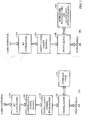
- Figure 1a shows a channel interleaver in accordance with an embodiment.
- Figure 1b shows a channel interleaver in accordance with another embodiment.
- the interleaver of figure 1b uses bit-interleaver solely to achieve m-ary modulation diversity and uses a two-dimension interleaved interlace table and run-time slot-to-interlace mapping to achieve frequency diversity which provides better interleaving performance without the need for explicit symbol interleaving.
- Figure 1a shows Turbo coded bits 102 input into bit interleaving block 104.
- Bit interleaving block 104 outputs interleaved bits, which are input into constellation symbol mapping block 106.
- Constellation symbol mapping block 106 outputs constellation symbol mapped bits, which are input into constellation symbol interleaving block 108.
- Constellation symbol interleaving block 108 outputs constellation symbol interleaved bits into channelization block 110.
- Channelization block 110 interlaces the constellation symbol interleaved bits using an interlace table 112 and outputs OFDM symbols 114.
- Figure 1b shows Turbo coded bits 152 input into bit interleaving block 154.
- Bit interleaving block 154 outputs interleaved bits, which are input into constellation symbol mapping block 156.
- Constellation symbol mapping block 15 outputs constellation symbol mapped bits, which are input into channelization block 158.
- Channelization block 158 channelizes the constellation symbol interleaved bits using an interleaved interlace table and dynamic slot-interlace mapping 160 and outputs OFDM symbols 162.
- the interleaver of figure 1b uses bit interleaving 154 to achieve modulation diversity.
- the code bits 152 of a turbo packet are interleaved in such a pattern that adjacent code bits are mapped into different constellation symbols.
- the N bit interleaver buffer are divided into N/m blocks. Adjacent code bits are written into adjacent blocks sequentially and then are read out one by one from the beginning of the buffer to the end in the sequential order, as shown in Figure 2a (Top). This guarantees that adjacent code bits be mapped to different constellation symbols.
- the interleaver buffer is arranged into an N/m rows by m columns matrix.
- Code bits are written into the buffer column by column and are read out row by row.
- rows shall be read out from left to right and right to left alternatively.
- Figure 2a shows code bits of a turbo packet 202 placed into an interleaving buffer 204 in accordance with an embodiment.
- Figure 2b is an illustration of bit interleaving operation in accordance with an embodiment.
- Code bits of a Turbo packet 250 are placed into an interleaving buffer 252 as shown in figure 2b .
- Interleaved code bits of a Turbo packet 256 are read from the interleaving buffer 254.
- the code bits of a turbo packet 202 are distributed into groups.
- the embodiments of both figure 2a and figure 2b also distribute the code bits into groups.
- the code bits within each group are shuffled according to a group bit order for each given group.
- the order of four groups of 16 code bits after being distributed into groups may be ⁇ 1, 5, 9, 13 ⁇ ⁇ 2, 6, 10, 14 ⁇ ⁇ 3, 7, 11, 15 ⁇ ⁇ 4, 8, 12, 16 ⁇ using a simple linear ordering of the groups and the order of the four groups of 16 code bits after shuffling may be ⁇ 13, 9, 5, 1 ⁇ ⁇ 2, 10, 6, 14 ⁇ ⁇ 11, 7, 15, 3 ⁇ ⁇ 12, 8, 4, 16 ⁇ .
- swapping rows or columns would be a regressive case of this intra-group shuffling.
- the channel interleaver uses interleaved interlace for constellation symbol interleaving to achieve frequency diversity. This eliminates the need for explicit constellation symbol interleaving.
- the interleaving is performed at two levels:
- 500 subcarriers of an interlace are interleaved in a bit-reversal fashion.
- Interlace Interleaving In an embodiment, eight interlaces are interleaved in a bit-reversal fashion.
- the number of subcarriers can be other than 500. It would also be apparent to those skilled in the art that the number of interlaces can be other than eight.
- bitRev is the regular bit reversal operation.
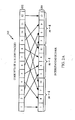
- the symbols of the constellation symbol sequence of a data channel is mapped into the corresponding subcarriers in a sequential linear fashion according to the assigned slot index, determined by a Channelizer, using the interlace table as is depicted in Figure 3 , in accordance with an embodiment.
- Figure 3 illustrates an interleaved interlace table in accordance with an embodiment.
- Turbo packet 302 constellation symbols 304, and interleaved interlace table 306 are shown. Also shown are interlace 3 (308), interlace 4 (310), interlace 2 (312), interlace 6 (314), interlace 1 (316), interlace 5 (318), interlace 3 (320), and interlace 7 (322).
- one out of the eight interlaces is used for pilot, i.e., Interlace 2 and Interlace 6 is used alternatively for pilot.
- the Channelizer can use seven interlaces for scheduling.
- the Channelizer uses Slot as a scheduling unit. A slot is defined as one interlace of an OFDM symbol. An Interlace Table is used to map a slot to a particular interlace. Since eight interlaces are used, there are then eight slots. Seven slots will be set aside for use for Channelization and one slot for Pilot.
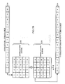
- Slot 0 is used for the Pilot and Slots 1 to 7 are used for Channelization, as is shown in Figure 4 where the vertical axis is the slot index 402, the horizontal axis is the OFDM symbol index 404 and the bold-faced entry is the interlace index assigned to the corresponding slot at an OFDM symbol time.
- Figure 4 shows a Channelization diagram in accordance with an embodiment.
- Figure 4 shows the slot indices reserved for the scheduler 406 and the slot index reserved for the Pilot 408.
- the bold faced entries are interlace index numbers. The number with square is the interlace adjacent to pilot and consequently with good channel estimate.
- the number surrounded with a square is the interlace adjacent to the pilot and consequently with good channel estimate. Since the Scheduler always assigns a chunk of contiguous slots and OFDM symbols to a data channel, it is clear that due to the inter-interlace interleaving, the contiguous slots that are assigned to a data channel will be mapped to discontinuous interlaces. More frequency diversity gain can then be achieved.
- this static assignment i.e., the slot to physical interlace mapping table1 does not change over time
- This static assignment does suffer one problem. That is, if a data channel assignment block (assuming rectangular) occupies multiple OFDM symbols, the interlaces assigned to the data channel does not change over the time, resulting in loss of frequency diversity.
- the remedy is simply cyclically shifting the Scheduler interlace table (i.e., excluding the Pilot interlace) from OFDM symbol to OFDM symbol. 1
- the Scheduler slot table does not include the Pilot slot.
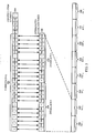
- Figure 5 depicts the operation of shifting the Scheduler interlace table once per OFDM symbol. This scheme successfully destroys the static interlace assignment problem, i.e., a particular slot is mapped to different interlaces at different OFDM symbol time.
- Figure 5 shows a channelization diagram with all one's shifting sequence resulting in long runs of good and poor channel estimates for a particular slot 502, in accordance with an embodiment.
- Figure 5 shows the slot indices reserved for the scheduler 506 and the slot index reserved for the Pilot 508.
- Slot symbol index 504 is shown on the horizontal axis.
- ⁇ N I- 1 is the number of interlaces used for traffic data scheduling, where I is the total number of interlaces;
- ⁇ i ⁇ ⁇ 0,1, ⁇ , I -1 ⁇ is the interlace index that Slot s at OFDM symbol t maps to;
- T -1 is the OFDM symbol index in a super frame, where T is the total number of OFDM symbols in a frame2; 2 OFDM symbol index in a superframe instead of in a frame gives additional diversity to frames since the number of OFDM symbols in a frame in the current design is not divisible by 14.
- ⁇ R is the number of shifts per OFDM symbol
- ⁇ is the reduced-set bit-reversal operator. That is, the interlace used by the Pilot shall be excluded from the bit-reversal operation.
- This table can be generated by the following code:
- bitRev is the regular bit reversal operation.
- Figure 6 shows a Channelization diagram with all two's shifting sequence resulting in evenly spread good and poor channel estimate interlaces.
- an interleaver has the following features:
- the bit interleaver is designed to taking advantage of m-Ary modulation diversity by interleaving the code bits into different modulation symbols;
- symbol interleaving designed to achieve frequency diversity by INTRA-interlace interleaving and INTER-interlace interleaving
- Additional frequency diversity gain and channel estimation gain are achieved by changing the slot-interlace mapping table from OFDM symbol to OFDM symbol.
- a simple rotation sequence is proposed to achieve this goal.
- FIG. 7 shows a wireless device configured to implement interleaving in accordance with an embodiment.
- Wireless device 702 comprises an antenna 704, duplexer 706, a receiver 708, a transmitter 710, processor 712, and memory 714.
- Processor 712 is capable of performing interleaving in accordance with an embodiment.
- the processor 712 uses memory 714 for buffers or data structures to perform its operations.
- DSP digital signal processor
- ASIC application specific integrated circuit
- FPGA field programmable gate array
- a general purpose processor may be a microprocessor, but in the alternative, the processor may be any conventional processor, controller, microcontroller, or state machine.
- a processor may also be implemented as a combination of computing devices, e.g., a combination of a DSP and a microprocessor, a plurality of microprocessors, one or more microprocessors in conjunction with a DSP core, or any other such configuration.
- a software module may reside in RAM memory, flash memory, ROM memory, EPROM memory, EEPROM memory, registers, hard disk, a removable disk, a CD-ROM, or any other form of storage medium known in the art.
- An exemplary storage medium is coupled to the processor such the processor can read information from, and write information to, the storage medium.
- the storage medium may be integral to the processor.
- the processor and the storage medium may reside in an ASIC.
- the ASIC may reside in a user terminal.
- the processor and the storage medium may reside as discrete components in a user terminal.
Abstract
Description
- The present Application for Patent claims priority to Provisional Application No.
60/592,999 - The present disclosed embodiments relates generally to wireless communications, and more specifically to channel interleaving in a wireless communications system.
- Orthogonal frequency division multiplexing (OFDM) is a technique for broadcasting high rate digital signals. In OFDM systems, a single high rate data stream is divided into several parallel low rate substreams, with each substream being used to modulate a respective subcarrier frequency. It should be noted that although the present invention is described in terms of quadrature amplitude modulation, it is equally applicable to phase shift keyed modulation systems.
- The modulation technique used in OFDM systems is referred to as quadrature amplitude modulation (QAM), in which both the phase and the amplitude of the carrier frequency are modulated. In QAM modulation, complex QAM symbols are generated from plural data bits, with each symbol including a real number term and an imaginary number term and with each symbol representing the plural data bits from which it was generated. A plurality of QAM bits are transmitted together in a pattern that can be graphically represented by a complex plane. Typically, the pattern is referred to as a "constellation". By using QAM modulation, an OFDM system can improve its efficiency.
- It happens that when a signal is broadcast, it can propagate to a receiver by more than one path. For example, a signal from a single transmitter can propagate along a straight line to a receiver, and it can also be reflected off of physical objects to propagate along a different path to the receiver. Moreover, it happens that when a system uses a so-called "cellular" broadcasting technique to increase spectral efficiency, a signal intended for a received might be broadcast by more than one transmitter. Hence, the same signal will be transmitted to the receiver along more than one path. Such parallel propagation of signals, whether man-made (i.e., caused by broadcasting the same signal from more than one transmitter) or natural (i.e., caused by echoes) is referred to as "multipath". It can be readily appreciated that while cellular digital broadcasting is spectrally efficient, provisions must be made to effectively address multipath considerations.
- Fortunately, OFDM systems that use QAM modulation are more effective in the presence of multipath conditions (which, as stated above, must arise when cellular broadcasting techniques are used) than are QAM modulation techniques in which only a single carrier frequency is used. More particularly, in single carrier QAM systems, a complex equalizer must be used to equalize channels that have echoes as strong as the primary path, and such equalization is difficult to execute. In contrast, in OFDM systems the need for complex equalizers can be eliminated altogether simply by inserting a guard interval of appropriate length at the beginning of each symbol. Accordingly, OFDM systems that use QAM modulation are preferred when multipath conditions are expected.
- In a typical trellis coding scheme, the data stream is encoded with a convolutional encoder and then successive bits are combined in a bit group that will become a QAM symbol. Several bits are in a group, with the number of bits per group being defined by an integer "m" (hence, each group is referred to as having an "m-ary" dimension). Typically, the value of "m" is four, five, six, or seven, although it can be more or less.
- After grouping the bits into multi-bit symbols, the symbols are interleaved. By "interleaving" is meant that the symbol stream is rearranged in sequence, to thereby randomize potential errors caused by channel degradation. To illustrate, suppose five words are to be transmitted. If, during transmission of a non-interleaved signal, a temporary channel disturbance occurs. Under these circumstances, an entire word can be lost before the channel disturbance abates, and it can be difficult if not impossible to know what information had been conveyed by the lost word.
- In contrast, if the letters of the five words are sequentially rearranged (i.e., "interleaved") prior to transmission and a channel disturbance occurs, several letters might be lost, perhaps one letter per word. Upon decoding the rearranged letters, however, all five words would appear, albeit with several of the words missing letters. It will be readily appreciated that under these circumstances, it would be relatively easy for a digital decoder to recover the data substantially in its entirety. After interleaving the m-ary symbols, the symbols are mapped to complex symbols using QAM principles noted above, multiplexed into their respective sub-carrier channels, and transmitted.
-
FIG. 1a shows a channel interleaver in accordance with an embodiment; -
FIG. 1b shows a channel interleaver in accordance with another embodiment; -
FIG. 2a shows code bits of a turbo packet placed into an interleaving buffer in accordance with an embodiment; -
FIG. 2b shows an interleaver buffer arranged into an N/m rows by m columns matrix in accordance with an embodiment; -
FIG. 3 illustrates an interleaved interlace table in accordance with an embodiment; -
FIG. 4 shows a channelization diagram in accordance with an embodiment; -
FIG. 5 shows a channelization diagram with all one's shifting sequence resulting in long runs of good and poor channel estimates for a particular slot, in accordance with an embodiment; and -
FIG. 6 shows a Channelization diagram with all two's shifting sequence resulting in evenly spread good and poor channel estimate interlaces; and -
FIG. 7 shows a wireless device configured to implement interleaving in accordance with an embodiment. - In an embodiment, a channel interleaver comprises a bit interleaver and a symbol interleaver.
Figure 1 shows two types of channel interleaving schemes. Both schemes use bit interleaving and interlacing to achieve maximum channel diversity. -
Figure 1a shows a channel interleaver in accordance with an embodiment.Figure 1b shows a channel interleaver in accordance with another embodiment. The interleaver offigure 1b uses bit-interleaver solely to achieve m-ary modulation diversity and uses a two-dimension interleaved interlace table and run-time slot-to-interlace mapping to achieve frequency diversity which provides better interleaving performance without the need for explicit symbol interleaving. -
Figure 1a shows Turbo codedbits 102 input intobit interleaving block 104. Bit interleavingblock 104 outputs interleaved bits, which are input into constellation symbol mapping block 106. Constellation symbol mapping block 106 outputs constellation symbol mapped bits, which are input into constellation symbol interleavingblock 108. Constellation symbol interleavingblock 108 outputs constellation symbol interleaved bits intochannelization block 110.Channelization block 110 interlaces the constellation symbol interleaved bits using an interlace table 112 andoutputs OFDM symbols 114. -
Figure 1b shows Turbo codedbits 152 input intobit interleaving block 154. Bit interleavingblock 154 outputs interleaved bits, which are input into constellationsymbol mapping block 156. Constellationsymbol mapping block 15 outputs constellation symbol mapped bits, which are input intochannelization block 158.Channelization block 158 channelizes the constellation symbol interleaved bits using an interleaved interlace table and dynamic slot-interlace mapping 160 andoutputs OFDM symbols 162. - Bit Interleaving for modulation diversity
- The interleaver of
figure 1b uses bit interleaving 154 to achieve modulation diversity. Thecode bits 152 of a turbo packet are interleaved in such a pattern that adjacent code bits are mapped into different constellation symbols. For example, for 2m-Ary modulation, the N bit interleaver buffer are divided into N/m blocks. Adjacent code bits are written into adjacent blocks sequentially and then are read out one by one from the beginning of the buffer to the end in the sequential order, as shown inFigure 2a (Top). This guarantees that adjacent code bits be mapped to different constellation symbols. Equivalently, as is illustrated inFigure 2b (Bottom), the interleaver buffer is arranged into an N/m rows by m columns matrix. Code bits are written into the buffer column by column and are read out row by row. To avoid the adjacent code bit to be mapped to the same bit position of the constellation symbol due to the fact that certain bits of a constellation symbol are more reliable than the others for 16QAM depending on the mapping, for example, the first and third bits are more reliable than the second and fourth bits, rows shall be read out from left to right and right to left alternatively. -
Figure 2a shows code bits of aturbo packet 202 placed into aninterleaving buffer 204 in accordance with an embodiment.Figure 2b is an illustration of bit interleaving operation in accordance with an embodiment. Code bits of aTurbo packet 250 are placed into aninterleaving buffer 252 as shown infigure 2b . Theinterleaving buffer 252 is transformed by swapping the second and third columns, thereby creatinginterleaving buffer 254, wherein m=4, in accordance with an embodiment. Interleaved code bits of aTurbo packet 256 are read from theinterleaving buffer 254. - For simplicity, a fixed m=4 may be used, if the highest modulation level is 16 and if code bit length is always divisible by 4. In this case, to improve the separation for QPSK, the middle two columns are swapped before being read out. This procedure is depicted in
Figure 2b (Bottom). It would be apparent to those skilled in the art that any two columns may be swapped. It would also be apparent to those skilled in the art that the columns may be placed in any order. It would also be apparent to those skilled in the art that the rows may be placed in any order. - In another embodiment, as a first step, the code bits of a
turbo packet 202 are distributed into groups. Note that the embodiments of bothfigure 2a andfigure 2b also distribute the code bits into groups. However, rather than simply swapping rows or columns, the code bits within each group are shuffled according to a group bit order for each given group. Thus, the order of four groups of 16 code bits after being distributed into groups may be {1, 5, 9, 13} {2, 6, 10, 14} {3, 7, 11, 15} {4, 8, 12, 16} using a simple linear ordering of the groups and the order of the four groups of 16 code bits after shuffling may be {13, 9, 5, 1} {2, 10, 6, 14} {11, 7, 15, 3} {12, 8, 4, 16}. Note that swapping rows or columns would be a regressive case of this intra-group shuffling. - Interleaved Interlace for frequency diversity
- In accordance with an embodiment, the channel interleaver uses interleaved interlace for constellation symbol interleaving to achieve frequency diversity. This eliminates the need for explicit constellation symbol interleaving. The interleaving is performed at two levels:
- · Within or Intra Interlace Interleaving: In an embodiment, 500 subcarriers of an interlace are interleaved in a bit-reversal fashion.
- · Between or Inter Interlace Interleaving: In an embodiment, eight interlaces are interleaved in a bit-reversal fashion.
- It would be apparent to those skilled in the art that the number of subcarriers can be other than 500. It would also be apparent to those skilled in the art that the number of interlaces can be other than eight.
- Note that since 500 is not power of 2, a reduced-set bit reversal operation shall be used in accordance with an embodiment. The following code shows the operation:
- vector<int> reducedSetBitRev(int n)
- int m=exponent(n);
- vector<int> y(n);
- for (int i=0, j=0; i<n; i++,j++)
- {
- int k;
- for (; (k=bitRev(j,m))>=n; j++);
- y[i]=k;
- return y;
- }
- where n=500, m is the smallest integer such that 2 m >n which is 8, and bitRev is the regular bit reversal operation.
- The symbols of the constellation symbol sequence of a data channel is mapped into the corresponding subcarriers in a sequential linear fashion according to the assigned slot index, determined by a Channelizer, using the interlace table as is depicted in
Figure 3 , in accordance with an embodiment. -
Figure 3 illustrates an interleaved interlace table in accordance with an embodiment.Turbo packet 302,constellation symbols 304, and interleaved interlace table 306 are shown. Also shown are interlace 3 (308), interlace 4 (310), interlace 2 (312), interlace 6 (314), interlace 1 (316), interlace 5 (318), interlace 3 (320), and interlace 7 (322). - In an embodiment, one out of the eight interlaces is used for pilot, i.e.,
Interlace 2 andInterlace 6 is used alternatively for pilot. As a result, the Channelizer can use seven interlaces for scheduling. For convenience, the Channelizer uses Slot as a scheduling unit. A slot is defined as one interlace of an OFDM symbol. An Interlace Table is used to map a slot to a particular interlace. Since eight interlaces are used, there are then eight slots. Seven slots will be set aside for use for Channelization and one slot for Pilot. Without loss of generality,Slot 0 is used for the Pilot andSlots 1 to 7 are used for Channelization, as is shown inFigure 4 where the vertical axis is theslot index 402, the horizontal axis is theOFDM symbol index 404 and the bold-faced entry is the interlace index assigned to the corresponding slot at an OFDM symbol time. -
Figure 4 shows a Channelization diagram in accordance with an embodiment.Figure 4 shows the slot indices reserved for thescheduler 406 and the slot index reserved for thePilot 408. The bold faced entries are interlace index numbers. The number with square is the interlace adjacent to pilot and consequently with good channel estimate. - The number surrounded with a square is the interlace adjacent to the pilot and consequently with good channel estimate. Since the Scheduler always assigns a chunk of contiguous slots and OFDM symbols to a data channel, it is clear that due to the inter-interlace interleaving, the contiguous slots that are assigned to a data channel will be mapped to discontinuous interlaces. More frequency diversity gain can then be achieved.
- However, this static assignment (i.e., the slot to physical interlace mapping table1 does not change over time) does suffer one problem. That is, if a data channel assignment block (assuming rectangular) occupies multiple OFDM symbols, the interlaces assigned to the data channel does not change over the time, resulting in loss of frequency diversity. The remedy is simply cyclically shifting the Scheduler interlace table (i.e., excluding the Pilot interlace) from OFDM symbol to OFDM symbol.
1 The Scheduler slot table does not include the Pilot slot. -
Figure 5 depicts the operation of shifting the Scheduler interlace table once per OFDM symbol. This scheme successfully destroys the static interlace assignment problem, i.e., a particular slot is mapped to different interlaces at different OFDM symbol time. -
Figure 5 shows a channelization diagram with all one's shifting sequence resulting in long runs of good and poor channel estimates for aparticular slot 502, in accordance with an embodiment.Figure 5 shows the slot indices reserved for thescheduler 506 and the slot index reserved for thePilot 508.Slot symbol index 504 is shown on the horizontal axis. - However, it is noticed that slots are assigned four continuous interlaces with good channel estimates followed by long runs of interlaces with poor channel estimates in contrast to the preferred patterns of short runs of good channel estimate interlaces and short runs of interlaces with poor channel estimates. In the figure, the interlace that is adjacent to the pilot interlace is marked with a square. A solution to the long runs of good and poor channel estimates problem is to use a shifting sequence other than the all one's sequence. There are many sequences can be used to fulfill this task. The simplest sequence is the all two's sequence, i.e., the Scheduler interlace table is shifted twice instead of once per OFDM symbol. The result is shown in
Figure 6 which significantly improves the Channelizer interlace pattern. Note that this pattern repeats every 2 × 7 = 14 OFDM symbols, where 2 is the Pilot interlace staggering period and 7 is the Channelizer interlace shifting period. - To simplify the operation at both transmitters and receivers, a simple formula can be used to determine the mapping from slot to interlace at a given OFDM symbol time
-

where - · N=I-1 is the number of interlaces used for traffic data scheduling, where I is the total number of interlaces;
- · i ∈ {0,1,···, I-1}, excluding the pilot interlace, is the interlace index that Slot s at OFDM symbol t maps to;
- · t = 0,1,···,T-1 is the OFDM symbol index in a super frame, where T is the total number of OFDM symbols in a frame2;
2 OFDM symbol index in a superframe instead of in a frame gives additional diversity to frames since the number of OFDM symbols in a frame in the current design is not divisible by 14. - · s=1,2,···,S-1 s is the slot index where S is the total number of slots;
- · R is the number of shifts per OFDM symbol;
- ·is the reduced-set bit-reversal operator. That is, the interlace used by the Pilot shall be excluded from the bit-reversal operation.

- Example: In an embodiment, I=8, R=2. The corresponding Slot-Interlace mapping formula becomes
-

- wherecorresponds to the following table:

- x ⇒ {x}

- 0 ⇒ 0
- 1 ⇒ 4
- 2 ⇒ 2 or 6
- 3 ⇒ 1
- 4 ⇒ 5
- 5 ⇒ 3
- 6 ⇒ 7
- This table can be generated by the following code:
- int reducedSetBitRev(int x, int exclude, int n)
- {
- int m=exponent(n);
- int y;
- for (int i=0; j=0; i<=x; i++, j++)
- for (; (y=bitRev(j, m))=exclude; j++);
- }
- return y;
- }
- where m=3 and bitRev is the regular bit reversal operation.
- For OFDM symbol t=11, Pilot uses
Interlace 6. The mapping between Slot and Interlace becomes: - ·
Slot 1 maps to interlace of{(7-(2×11)%7+1-1)%7} = {6} = 7;
- ·
Slot 2 maps to interlace of {(7-(2×11)%7+2-1)%7} = {0} = 0; - ·
Slot 3 maps to interlace of {(7-(2×11)%7+3-1)%7} = {1} = 4; - ·
Slot 4 maps to interlace of {(7-(2×11)%7+4-1)%7} = {2} = 2; - ·
Slot 5 maps to interlace of {(7-(2×11)%7+5-1)%7} = {3} = 1; - ·
Slot 6 maps to interlace of {(7-(2×11)%7+6-1)%7} = {4} = 5; - ·
Slot 7 maps to interlace of {(7-(2×11)%7+7-1)%7} = {5} =3. - The resulting mapping agrees with the mapping in
Figure 6. Figure 6 shows a Channelization diagram with all two's shifting sequence resulting in evenly spread good and poor channel estimate interlaces. - In accordance with an embodiment, an interleaver has the following features:
- The bit interleaver is designed to taking advantage of m-Ary modulation diversity by interleaving the code bits into different modulation symbols;
- The "symbol interleaving" designed to achieve frequency diversity by INTRA-interlace interleaving and INTER-interlace interleaving;
- Additional frequency diversity gain and channel estimation gain are achieved by changing the slot-interlace mapping table from OFDM symbol to OFDM symbol. A simple rotation sequence is proposed to achieve this goal.
-
Figure 7 shows a wireless device configured to implement interleaving in accordance with an embodiment.Wireless device 702 comprises anantenna 704,duplexer 706, areceiver 708, atransmitter 710,processor 712, andmemory 714.Processor 712 is capable of performing interleaving in accordance with an embodiment. Theprocessor 712 usesmemory 714 for buffers or data structures to perform its operations. - The attached chapter describes details of further embodiments.
- Those of skill in the art would understand that information and signals may be represented using any of a variety of different technologies and techniques. For example, data, instructions, commands, information, signals, bits, symbols, and chips that may be referenced throughout the above description may be represented by voltages, currents, electromagnetic waves, magnetic fields or particles, optical fields or particles, or any combination thereof.
- Those of skill would further appreciate that the various illustrative logical blocks, modules, circuits, and algorithm steps described in connection with the embodiments disclosed herein may be implemented as electronic hardware, computer software, or combinations of both. To clearly illustrate this interchangeability of hardware and software, various illustrative components, blocks, modules, circuits, and steps have been described above generally in terms of their functionality. Whether such functionality is implemented as hardware or software depends upon the particular application and design constraints imposed on the overall system. Skilled artisans may implement the described functionality in varying ways for each particular application, but such implementation decisions should not be interpreted as causing a departure from the scope of the present invention.
- The various illustrative logical blocks, modules, and circuits described in connection with the embodiments disclosed herein may be implemented or performed with a general purpose processor, a digital signal processor (DSP), an application specific integrated circuit (ASIC), a field programmable gate array (FPGA) or other programmable logic device, discrete gate or transistor logic, discrete hardware components, or any combination thereof designed to perform the functions described herein. A general purpose processor may be a microprocessor, but in the alternative, the processor may be any conventional processor, controller, microcontroller, or state machine. A processor may also be implemented as a combination of computing devices, e.g., a combination of a DSP and a microprocessor, a plurality of microprocessors, one or more microprocessors in conjunction with a DSP core, or any other such configuration.
- The steps of a method or algorithm described in connection with the embodiments disclosed herein may be embodied directly in hardware, in a software module executed by a processor, or in a combination of the two. A software module may reside in RAM memory, flash memory, ROM memory, EPROM memory, EEPROM memory, registers, hard disk, a removable disk, a CD-ROM, or any other form of storage medium known in the art. An exemplary storage medium is coupled to the processor such the processor can read information from, and write information to, the storage medium. In the alternative, the storage medium may be integral to the processor. The processor and the storage medium may reside in an ASIC. The ASIC may reside in a user terminal. In the alternative, the processor and the storage medium may reside as discrete components in a user terminal.
- The previous description of the disclosed embodiments is provided to enable any person skilled in the art to make or use the present invention. Various modifications to these embodiments will be readily apparent to those skilled in the art, and the generic principles defined herein may be applied to other embodiments without departing from the spirit or scope of the invention. Thus, the present invention is not intended to be limited to the embodiments shown herein but is to be accorded the widest scope consistent with the principles and novel features disclosed herein.


- In the following, further examples are described to facilitate the understanding of the invention:
- 1. A method for interleaving, comprising:
- inter-interleave subcarriers of an interlace; and
- intra-interleave the interlaces.
- 2. The method of 1, wherein the number of sub carriers is 500.
- 3. The method of 2, wherein the number of interlaces is eight.
- 4. The method of 1, wherein the inter-intorleave subcarriers of an interlace involves mapping symbols of a constellation symbol sequence into corresponding subcarriers in a sequential linear fashion according to an assigned slot index using an interlace table.
- 5. A processor configured to:
- interleave subcarriers of an interlace; and
- interleave the interlaces.
- 6. A processor, comprising:
- means for interleaving subcarriers of an interlace; and
- means for interleaving the interlaces.
- 7. A readable media embodying a method for interleaving, comprising:
- interleaving subcarriers of an interlace; and
- interleaving the interlaces.
Claims (10)
- A method for improving frequency diversity in an OFDM system using interleaved interlaces for constellation symbol interleaving, comprising:interleaving a number of subcarriers of an interlace in a bit reversal fashion; andinterleaving a number of interlaces in the bit reversal fashion.
- The method of claim 1, wherein the bit reversal fashion is a reduced-set bit reversal operation if the number of subcarriers is not a power of two.
- The method of claim 2, wherein the number of subcarriers is 500.
- The method of claim 3, wherein the number of interlaces is eight.
- The method of claim 1, wherein the interleave subcarriers of an interlace in a bit reversal fashion involves mapping symbols of a constellation symbol sequence into corresponding subcarriers in a sequential linear fashion according to an assigned slot index using an interlace table.
- The method of claim 1, wherein the rearranging the sequence of subcarriers further comprises shifting an interlace sequence table at least once per OFDM symbol.
- The method of claim 1, wherein the rearranging the sequence of subcarriers further comprises shifting an interlace sequence table at least twice per OFDM symbol.
- An apparatus, comprising:means for interleaving a number of subcarriers of an interlace in a bit reversal fashion; andmeans for interleaving a number of interlaces in the bit reversal fashion.
- A processor comprising modules configured to perform all the steps of the method of any of claims 1 to 7.
- A computer program comprising instructions that when executed by a computer system causes the computer system to perform the method of any of claims 1 to 7.
Applications Claiming Priority (2)
| Application Number | Priority Date | Filing Date | Title |
|---|---|---|---|
| US59299904P | 2004-07-29 | 2004-07-29 | |
| EP05776851A EP1771961A2 (en) | 2004-07-29 | 2005-07-29 | System and method for interleaving |
Related Parent Applications (1)
| Application Number | Title | Priority Date | Filing Date |
|---|---|---|---|
| EP05776851A Division EP1771961A2 (en) | 2004-07-29 | 2005-07-29 | System and method for interleaving |
Publications (1)
| Publication Number | Publication Date |
|---|---|
| EP2512058A1 true EP2512058A1 (en) | 2012-10-17 |
Family
ID=35169875
Family Applications (4)
| Application Number | Title | Priority Date | Filing Date |
|---|---|---|---|
| EP05777262A Withdrawn EP1771963A1 (en) | 2004-07-29 | 2005-07-29 | System and method for interleaving |
| EP05776851A Withdrawn EP1771961A2 (en) | 2004-07-29 | 2005-07-29 | System and method for interleaving |
| EP12176160A Withdrawn EP2512058A1 (en) | 2004-07-29 | 2005-07-29 | Method and apparatus for frequency diversity |
| EP05777259.2A Active EP1771962B1 (en) | 2004-07-29 | 2005-07-29 | System and method for diversity interleaving |
Family Applications Before (2)
| Application Number | Title | Priority Date | Filing Date |
|---|---|---|---|
| EP05777262A Withdrawn EP1771963A1 (en) | 2004-07-29 | 2005-07-29 | System and method for interleaving |
| EP05776851A Withdrawn EP1771961A2 (en) | 2004-07-29 | 2005-07-29 | System and method for interleaving |
Family Applications After (1)
| Application Number | Title | Priority Date | Filing Date |
|---|---|---|---|
| EP05777259.2A Active EP1771962B1 (en) | 2004-07-29 | 2005-07-29 | System and method for diversity interleaving |
Country Status (17)
| Country | Link |
|---|---|
| US (3) | US9003243B2 (en) |
| EP (4) | EP1771963A1 (en) |
| JP (7) | JP4694568B2 (en) |
| KR (3) | KR100905350B1 (en) |
| CN (4) | CN101091346B (en) |
| AU (3) | AU2005267809B2 (en) |
| BR (3) | BRPI0513885A (en) |
| CA (3) | CA2575551A1 (en) |
| IL (3) | IL181039A0 (en) |
| MX (3) | MX2007001166A (en) |
| NO (3) | NO20070896L (en) |
| NZ (2) | NZ552962A (en) |
| RU (3) | RU2376709C2 (en) |
| SG (2) | SG155170A1 (en) |
| UA (1) | UA90481C2 (en) |
| WO (3) | WO2006015268A2 (en) |
| ZA (3) | ZA200701275B (en) |
Families Citing this family (85)
| Publication number | Priority date | Publication date | Assignee | Title |
|---|---|---|---|---|
| GB2454193B (en) * | 2007-10-30 | 2012-07-18 | Sony Corp | Data processing apparatus and method |
| US8885761B2 (en) | 2003-03-25 | 2014-11-11 | Sony Corporation | Data processing apparatus and method |
| US8179954B2 (en) | 2007-10-30 | 2012-05-15 | Sony Corporation | Odd interleaving only of an odd-even interleaver when half or less data subcarriers are active in a digital video broadcasting (DVB) standard |
| US8599764B2 (en) | 2003-09-02 | 2013-12-03 | Qualcomm Incorporated | Transmission of overhead information for reception of multiple data streams |
| US8477809B2 (en) | 2003-09-02 | 2013-07-02 | Qualcomm Incorporated | Systems and methods for generalized slot-to-interlace mapping |
| US8509051B2 (en) | 2003-09-02 | 2013-08-13 | Qualcomm Incorporated | Multiplexing and transmission of multiple data streams in a wireless multi-carrier communication system |
| US7221680B2 (en) | 2003-09-02 | 2007-05-22 | Qualcomm Incorporated | Multiplexing and transmission of multiple data streams in a wireless multi-carrier communication system |
| US8526412B2 (en) | 2003-10-24 | 2013-09-03 | Qualcomm Incorporated | Frequency division multiplexing of multiple data streams in a wireless multi-carrier communication system |
| US8068530B2 (en) * | 2004-06-18 | 2011-11-29 | Qualcomm Incorporated | Signal acquisition in a wireless communication system |
| US20080317142A1 (en) * | 2005-07-29 | 2008-12-25 | Qualcomm Incorporated | System and method for frequency diversity |
| US8391410B2 (en) * | 2004-07-29 | 2013-03-05 | Qualcomm Incorporated | Methods and apparatus for configuring a pilot symbol in a wireless communication system |
| JP4694568B2 (en) | 2004-07-29 | 2011-06-08 | クゥアルコム・インコーポレイテッド | System and method for frequency diversity |
| US20070081484A1 (en) * | 2004-07-29 | 2007-04-12 | Wang Michael M | Methods and apparatus for transmitting a frame structure in a wireless communication system |
| US9246728B2 (en) * | 2004-07-29 | 2016-01-26 | Qualcomm Incorporated | System and method for frequency diversity |
| US7813383B2 (en) * | 2005-03-10 | 2010-10-12 | Qualcomm Incorporated | Method for transmission of time division multiplexed pilot symbols to aid channel estimation, time synchronization, and AGC bootstrapping in a multicast wireless system |
| BRPI0609275A2 (en) * | 2005-03-10 | 2010-03-09 | Qualcomm Inc | timing timing and channel estimation in a transition between local and enlarged area waveforms using designated tdm pilot |
| US7688904B2 (en) * | 2005-05-12 | 2010-03-30 | Intellon Corporation | Generating signals for transmission of information |
| CN101989892B (en) * | 2005-07-27 | 2013-07-17 | 高通股份有限公司 | System and method for forward link physical layer |
| US9042212B2 (en) * | 2005-07-29 | 2015-05-26 | Qualcomm Incorporated | Method and apparatus for communicating network identifiers in a communication system |
| US9391751B2 (en) | 2005-07-29 | 2016-07-12 | Qualcomm Incorporated | System and method for frequency diversity |
| US7733968B2 (en) * | 2005-09-27 | 2010-06-08 | Qualcomm Incorporated | Evaluation of transmitter performance |
| US20070070877A1 (en) * | 2005-09-27 | 2007-03-29 | Thomas Sun | Modulation type determination for evaluation of transmitter performance |
| US20070127358A1 (en) * | 2005-11-23 | 2007-06-07 | Qualcomm Incorporated | Phase correction in a test receiver |
| US7706328B2 (en) | 2006-01-04 | 2010-04-27 | Qualcomm Incorporated | Methods and apparatus for position location in a wireless network |
| US7983143B2 (en) * | 2006-02-08 | 2011-07-19 | Motorola Mobility, Inc. | Method and apparatus for initial acquisition and cell search for an OFDMA system |
| US7911935B2 (en) * | 2006-02-08 | 2011-03-22 | Motorola Mobility, Inc. | Method and apparatus for interleaving sequence elements of an OFDMA synchronization channel |
| KR101260836B1 (en) * | 2006-02-28 | 2013-05-06 | 삼성전자주식회사 | Pre-coding method for providing diversity gain in an orthogonal frequency division multiplexing system and transmitting apparatus and method using the same |
| US7782806B2 (en) | 2006-03-09 | 2010-08-24 | Qualcomm Incorporated | Timing synchronization and channel estimation at a transition between local and wide area waveforms using a designated TDM pilot |
| US20070242754A1 (en) * | 2006-04-04 | 2007-10-18 | Samsung Electronics Co., Ltd. | Apparatus for processing data stream for digital broadcasting system and method thereof |
| US7734303B2 (en) * | 2006-04-12 | 2010-06-08 | Qualcomm Incorporated | Pilot modulation error ratio for evaluation of transmitter performance |
| US8738056B2 (en) * | 2006-05-22 | 2014-05-27 | Qualcomm Incorporation | Signal acquisition in a wireless communication system |
| US20070280235A1 (en) * | 2006-06-01 | 2007-12-06 | Qualcomm Incorporated | System and method for acquisition and delivery of services to devices in a wireless multicast communication system |
| US8929353B2 (en) * | 2007-05-09 | 2015-01-06 | Qualcomm Incorporated | Preamble structure and acquisition for a wireless communication system |
| BRPI0712926B1 (en) * | 2006-06-13 | 2019-11-12 | Qualcomm Inc | preamble and acquisition structure for a wireless communication system |
| CA2653605A1 (en) * | 2006-06-21 | 2007-12-27 | Qualcomm Incorporated | Methods and apparatus for measuring, communicating and/or using interference information |
| CA2653602A1 (en) * | 2006-06-21 | 2007-12-27 | Qualcomm Incorporated | Wireless resource allocation methods and apparatus |
| TWI372539B (en) | 2006-06-23 | 2012-09-11 | Qualcomm Inc | Methods and systems for processing overhead reduction for control channel packets |
| US9008198B2 (en) * | 2007-01-05 | 2015-04-14 | Qualcomm Incorporated | Methods and apparatus for timing synchronization based on transitional pilot symbols |
| US8817896B2 (en) * | 2007-05-02 | 2014-08-26 | Koninklijke Philips N.V. | Method and device for allocating resources in an OFDM network |
| EP2003836B1 (en) * | 2007-06-15 | 2018-04-04 | Samsung Electronics Co., Ltd. | Data transmission and reception of data comprising symbols of different priorities |
| EP2003835A1 (en) | 2007-06-15 | 2008-12-17 | Nokia Siemens Networks Oy | Method for operating a radio communication system, receiver station and radio communication system |
| US7899125B2 (en) * | 2007-06-18 | 2011-03-01 | Intel Corporation | Method, device, and apparatus for multi-stream multi-band transmission |
| KR101505193B1 (en) * | 2007-06-18 | 2015-03-23 | 삼성전자주식회사 | Symbol Transmission Method and Apparatus for used in Orthogonal Frequency Division Multiplex Access Systems |
| KR101414758B1 (en) * | 2007-07-03 | 2014-10-01 | 삼성전자주식회사 | Apparatus for transmitting data and receiving data |
| US20090028100A1 (en) * | 2007-07-25 | 2009-01-29 | Qualcomm Incorporated | Methods and apparatus for transmitter identification in a wireless network |
| US8311133B2 (en) * | 2007-07-26 | 2012-11-13 | Qualcomm Incorporated | Method and apparatus for sensing signaling parameters in a wireless communications network |
| TWI395447B (en) * | 2007-08-06 | 2013-05-01 | Qualcomm Inc | Systems and methods for generalized slot-to-interlace mapping |
| ES2615635T3 (en) * | 2007-08-08 | 2017-06-07 | Telefonaktiebolaget Lm Ericsson (Publ) | Multi-carrier communication system that employs explicit frequency hopping |
| US8261168B2 (en) * | 2007-09-17 | 2012-09-04 | Lg Electronics Inc. | Code combining soft handoff in wireless communication system |
| CN103873419B (en) * | 2007-09-18 | 2017-11-17 | Lg电子株式会社 | The method of broadcast data is handled in transmitters and handles the emitter of broadcast data |
| US8848913B2 (en) * | 2007-10-04 | 2014-09-30 | Qualcomm Incorporated | Scrambling sequence generation in a communication system |
| EP2405584B1 (en) | 2007-10-30 | 2016-04-06 | Sony Corporation | Data processing apparatus and methods |
| DK2056471T3 (en) | 2007-10-30 | 2009-11-30 | Sony Corp | Data processing apparatus and method |
| DK2204002T3 (en) | 2007-10-30 | 2013-06-17 | Sony Corp | DEVICE AND PROCEDURE FOR DATA PROCESSING |
| US8787181B2 (en) | 2008-01-14 | 2014-07-22 | Qualcomm Incorporated | Resource allocation randomization |
| US8165064B2 (en) * | 2008-01-28 | 2012-04-24 | Qualcomm Incorporated | Enhancements to the positioning pilot channel |
| US9397779B2 (en) * | 2008-01-29 | 2016-07-19 | Koninklijke Philips N.V. | Method of packet retransmission and reception and wireless device employing the same |
| CN101521647B (en) * | 2008-02-26 | 2012-12-12 | 华为技术有限公司 | Subcarrier data mapping method, device and base station thereby |
| US8923249B2 (en) | 2008-03-26 | 2014-12-30 | Qualcomm Incorporated | Method and apparatus for scrambling sequence generation in a communication system |
| US8982832B2 (en) | 2008-04-28 | 2015-03-17 | Qualcomm Incorporated | Wireless communication of turbo coded data with time diversity |
| US20090274099A1 (en) * | 2008-05-02 | 2009-11-05 | Qualcomm Incorporated | Methods and apparatus for communicating transmitter information in a communication network |
| US7782903B2 (en) * | 2008-05-14 | 2010-08-24 | Newport Media, Inc. | Hardware accelerated protocol stack |
| US8102791B2 (en) | 2008-07-25 | 2012-01-24 | Newport Media, Inc. | Interleaver address generation in turbo decoders for mobile multimedia multicast system communication systems |
| US8792899B2 (en) * | 2008-11-07 | 2014-07-29 | Qualcomm Incorporated | Regionalized delivery of hybrid mobile broadcast services or channels in a mobile broadcast network |
| KR101657501B1 (en) * | 2009-01-07 | 2016-09-19 | 엘지전자 주식회사 | Apparatus and Method Of Tranmsitting A Signal |
| US8787497B2 (en) | 2009-02-12 | 2014-07-22 | Lg Electronics Inc. | Apparatus for transmitting and receiving a signal and method of transmitting and receiving a signal |
| FR2944171B1 (en) * | 2009-04-03 | 2012-12-21 | Get Enst | METHOD AND MODULATION DEVICE USING DIFFERENTIAL MODULATION, METHOD AND DEVICE FOR DEMODULATION, SIGNAL AND CORRESPONDING COMPUTER PROGRAM PRODUCTS. |
| US8612820B2 (en) | 2009-04-11 | 2013-12-17 | Qualcomm Incorporated | Apparatus and methods for interleaving in a forward link only system |
| US8396150B2 (en) | 2009-12-22 | 2013-03-12 | Intel Corporation | Tone count selection |
| US8665697B1 (en) * | 2009-12-23 | 2014-03-04 | Kbc Research Foundation Pvt. Ltd. | Subchannel formation in OFDMA systems |
| US20110195658A1 (en) * | 2010-02-11 | 2011-08-11 | Electronics And Telecommunications Research Institute | Layered retransmission apparatus and method, reception apparatus and reception method |
| US20110194645A1 (en) * | 2010-02-11 | 2011-08-11 | Electronics And Telecommunications Research Institute | Layered transmission apparatus and method, reception apparatus, and reception method |
| US8824590B2 (en) * | 2010-02-11 | 2014-09-02 | Electronics And Telecommunications Research Institute | Layered transmission apparatus and method, reception apparatus and reception method |
| JP5611893B2 (en) * | 2011-05-25 | 2014-10-22 | 日本電信電話株式会社 | Wireless communication system |
| US8850276B2 (en) * | 2011-09-22 | 2014-09-30 | Lsi Corporation | Systems and methods for efficient data shuffling in a data processing system |
| US9645820B2 (en) | 2013-06-27 | 2017-05-09 | Intel Corporation | Apparatus and method to reserve and permute bits in a mask register |
| US9942008B1 (en) * | 2014-02-10 | 2018-04-10 | Marvell International Ltd. | Systems and methods for range extension by time repetition |
| GB2523363B (en) * | 2014-02-21 | 2017-06-28 | Samsung Electronics Co Ltd | Bit interleaver and bit de-interleaver |
| CA2935256A1 (en) * | 2014-02-21 | 2015-08-27 | Huawei Technologies Co., Ltd. | Rate matching method and apparatus for polar code |
| MX366730B (en) | 2014-12-22 | 2019-07-22 | Huawei Tech Co Ltd | Polar code coding method and coding device. |
| WO2017209418A2 (en) * | 2016-05-31 | 2017-12-07 | 한국전자통신연구원 | Method and apparatus for non-orthogonal based uplink transmission |
| KR102322497B1 (en) | 2016-05-31 | 2021-11-09 | 한국전자통신연구원 | Non-orthogonal based uplink transmission method and apparatus |
| WO2018128873A1 (en) * | 2017-01-09 | 2018-07-12 | Intel IP Corporation | Systems, methods and devices for meeting cellular data turnaround time |
| CN107395546B (en) * | 2017-08-30 | 2020-04-24 | 重庆物奇科技有限公司 | Method for carrying out frequency domain information expansion on data symbols in power line carrier communication |
| US20200403640A1 (en) * | 2018-01-12 | 2020-12-24 | Lg Electronics Inc. | Method for performing interleaving and interleaver |
Citations (4)
| Publication number | Priority date | Publication date | Assignee | Title |
|---|---|---|---|---|
| EP0938208A1 (en) * | 1998-02-22 | 1999-08-25 | Sony International (Europe) GmbH | Multicarrier transmission, compatible with the existing GSM system |
| WO2001005059A1 (en) * | 1999-07-08 | 2001-01-18 | Samsung Electronics Co., Ltd. | Apparatus and method for controlling a demultiplexer and a multiplexer used for rate matching in a mobile communication system |
| EP1304812A1 (en) * | 2001-10-19 | 2003-04-23 | Texas Instruments Incorporated | Simplified noise estimation for orthogonal frequency division multiplexing communication systems |
| US20030174686A1 (en) * | 2002-03-14 | 2003-09-18 | Serge Willenegger | Method and apparatus for reducing inter-channel interference in a wireless communication system |
Family Cites Families (127)
| Publication number | Priority date | Publication date | Assignee | Title |
|---|---|---|---|---|
| US3017A (en) * | 1843-03-21 | Plate turn-button for fastening cupboard and other doors | ||
| US4672605A (en) | 1984-03-20 | 1987-06-09 | Applied Spectrum Technologies, Inc. | Data and voice communications system |
| SU1327296A1 (en) | 1985-06-11 | 1987-07-30 | Минский радиотехнический институт | Convolution coder with algorithm of threshold decoding |
| US5177766A (en) | 1991-06-03 | 1993-01-05 | Spectralink Corporation | Digital clock timing generation in a spread-spectrum digital communication system |
| US5315592A (en) * | 1992-04-23 | 1994-05-24 | Xyplex Inc. | Parallel bridging |
| AU664084B2 (en) | 1992-06-03 | 1995-11-02 | Ciba-Geigy Ag | Novel thiosemicarbazonic acid esters |
| US5346370A (en) | 1993-11-08 | 1994-09-13 | Graco Inc. | Portable pumping system with generator powered clutch assembly |
| US6154484A (en) | 1995-09-06 | 2000-11-28 | Solana Technology Development Corporation | Method and apparatus for embedding auxiliary data in a primary data signal using frequency and time domain processing |
| FI955113A (en) | 1995-10-26 | 1997-04-27 | Nokia Mobile Phones Ltd | Procedure for data communication, transmitters and receivers |
| FR2742612B1 (en) | 1995-12-15 | 1998-02-06 | Sextant Avionique | METHOD AND CIRCUIT FOR RECEIVING POSITIONING SIGNALS BY SATELLITES WITH ELIMINATION OF MULTI-PATH ERRORS |
| JP2907104B2 (en) | 1996-03-27 | 1999-06-21 | 日本電気株式会社 | Time diversity communication method and communication device |
| KR100186627B1 (en) | 1996-09-21 | 1999-05-15 | 삼성전자 주식회사 | Base band interlever |
| KR100193846B1 (en) | 1996-10-02 | 1999-06-15 | 윤종용 | Interleaved Read Address Generator |
| KR100221336B1 (en) | 1996-12-28 | 1999-09-15 | 전주범 | Frame harmonic apparatus and method of multi-receiver system |
| US6157746A (en) * | 1997-02-12 | 2000-12-05 | Sarnoff Corporation | Apparatus and method for encoding wavelet trees generated by a wavelet-based coding method |
| US6243379B1 (en) | 1997-04-04 | 2001-06-05 | Ramp Networks, Inc. | Connection and packet level multiplexing between network links |
| US6421333B1 (en) | 1997-06-21 | 2002-07-16 | Nortel Networks Limited | Channel coding and interleaving for transmission on a multicarrier system |
| EP0897223B1 (en) * | 1997-08-14 | 2013-03-20 | Her Majesty The Queen In Right Of Canada as represented by the Minister of Industry | High-performance low-complexity error-correcting codes |
| US6208663B1 (en) * | 1997-08-29 | 2001-03-27 | Telefonaktiebolaget Lm Ericsson (Publ) | Method and system for block ARQ with reselection of FEC coding and/or modulation |
| US6026117A (en) * | 1997-10-23 | 2000-02-15 | Interdigital Technology Corporation | Method and apparatus for generating complex four-phase sequences for a CDMA communication system |
| JP2961105B1 (en) | 1998-06-19 | 1999-10-12 | 株式会社次世代デジタルテレビジョン放送システム研究所 | OFDM receiver |
| JP2958308B1 (en) | 1998-07-10 | 1999-10-06 | 松下電器産業株式会社 | De-interleaving device |
| WO2000007300A1 (en) | 1998-07-27 | 2000-02-10 | Koninklijke Philips Electronics N.V. | Encoding multiword information by wordwise interleaving |
| US6298463B1 (en) * | 1998-07-31 | 2001-10-02 | Nortel Networks Limited | Parallel concatenated convolutional coding |
| US6798736B1 (en) * | 1998-09-22 | 2004-09-28 | Qualcomm Incorporated | Method and apparatus for transmitting and receiving variable rate data |
| CA2320480A1 (en) | 1998-12-04 | 2000-06-15 | U.S. Wireless Corporation | Wireless location determination using spatial signature information |
| KR100306282B1 (en) | 1998-12-10 | 2001-11-02 | 윤종용 | Apparatus and for interleaving and deinterleaving frame date in communication system |
| US6847658B1 (en) * | 1998-12-10 | 2005-01-25 | Qualcomm, Incorporated | Demultiplexer for channel interleaving |
| BE1012331A3 (en) | 1998-12-11 | 2000-09-05 | Steveninck Etienne | METHOD AND DEVICE FOR APPLYING reflective material on a substrate. |
| US6611551B1 (en) * | 1999-01-21 | 2003-08-26 | Cisco Technology, Inc. | OFDM channel identification |
| US6304581B1 (en) | 1999-02-16 | 2001-10-16 | Motorola, Inc. | Interleaving method and apparatus for orthogonal transmit diversity and multi-carriers CDMA communication systems |
| AU2692300A (en) | 1999-02-25 | 2000-09-14 | Nippon Hoso Kyokai | Digital broadcasting apparatus |
| KR100342565B1 (en) * | 1999-04-20 | 2002-07-04 | 윤종용 | Method for recovering a dropped call and informing the recovering state of mobile station in code division multipule access system |
| US6311306B1 (en) | 1999-04-26 | 2001-10-30 | Motorola, Inc. | System for error control by subdividing coded information units into subsets reordering and interlacing the subsets, to produce a set of interleaved coded information units |
| EP1914895B1 (en) * | 1999-05-10 | 2017-11-01 | NTT DoCoMo, Inc. | Data multiplexing method and data multiplexer, and data transmitting method and data transmitter |
| US6473878B1 (en) | 1999-05-28 | 2002-10-29 | Lucent Technologies Inc. | Serial-concatenated turbo codes |
| EP1055941B1 (en) * | 1999-05-28 | 2006-10-04 | Mitsubishi Denki Kabushiki Kaisha | Coherent laser radar apparatus and radar/optical communication system |
| FR2797122B1 (en) * | 1999-07-30 | 2006-08-04 | Commissariat Energie Atomique | METHOD OF TRANSMITTING DATA USING REPETITIVE REPETITIVE SETS OF RELEASE SEQUENCES, TRANSMITTER AND RECEIVER CORRESPONDING |
| US6747948B1 (en) | 1999-08-11 | 2004-06-08 | Lucent Technologies Inc. | Interleaver scheme in an OFDM system with multiple-stream data sources |
| US6631125B1 (en) | 1999-10-20 | 2003-10-07 | Nokia Corporation | Channel set-up in wideband, code division multiple access systems |
| US6697990B2 (en) | 1999-12-15 | 2004-02-24 | Hughes Electronics Corporation | Interleaver design for parsed parallel concatenated codes |
| IT1314319B1 (en) | 1999-12-23 | 2002-12-09 | Siemens Inf & Comm Networks | INTERLACING METHOD OF A BIT FLOW IN A RADIO MOBILE PHONE SYSTEM |
| JP2001217861A (en) | 2000-01-31 | 2001-08-10 | Kddi Corp | Prankster prevention system and mail center system |
| US6505052B1 (en) | 2000-02-01 | 2003-01-07 | Qualcomm, Incorporated | System for transmitting and receiving short message service (SMS) messages |
| JP3568873B2 (en) | 2000-03-22 | 2004-09-22 | 株式会社エヌ・ティ・ティ・ドコモ | Channel estimation method and apparatus in multicarrier wireless transmission system |
| KR100499467B1 (en) | 2000-03-10 | 2005-07-07 | 엘지전자 주식회사 | Block interleaving method, and apparatus for the same |
| JP3976474B2 (en) | 2000-05-12 | 2007-09-19 | 三洋電機株式会社 | OFDM demodulator |
| US7120696B1 (en) * | 2000-05-19 | 2006-10-10 | Stealthkey, Inc. | Cryptographic communications using pseudo-randomly generated cryptography keys |
| JP3995390B2 (en) | 2000-05-26 | 2007-10-24 | 三洋電機株式会社 | Digital broadcast receiver |
| JP2002057640A (en) | 2000-08-09 | 2002-02-22 | Sony Corp | Terrestrial digital broadcast transmitting and receiving system and terrestrial digital broadcast receiving equipment |
| US6985434B2 (en) | 2000-09-01 | 2006-01-10 | Nortel Networks Limited | Adaptive time diversity and spatial diversity for OFDM |
| JP2002217894A (en) | 2000-09-28 | 2002-08-02 | Hitachi Ltd | Method for data distribution service |
| JP2002111621A (en) | 2000-09-28 | 2002-04-12 | Sanyo Electric Co Ltd | Digital-signal receiving apparatus |
| US6754170B1 (en) * | 2000-09-29 | 2004-06-22 | Symbol Technologies, Inc. | Timing synchronization in OFDM communications receivers |
| JP2002111631A (en) | 2000-10-04 | 2002-04-12 | Yrp Mobile Telecommunications Key Tech Res Lab Co Ltd | System and apparatus for radio communication |
| US6961388B2 (en) * | 2001-02-01 | 2005-11-01 | Qualcomm, Incorporated | Coding scheme for a wireless communication system |
| KR100438448B1 (en) | 2001-02-13 | 2004-07-03 | 삼성전자주식회사 | Apparatus and method for generating codes in communication system |
| US7248652B2 (en) * | 2001-02-28 | 2007-07-24 | Agere Systems Inc. | Method and apparatus for recovering timing information in orthogonal frequency division multiplexing (OFDM) systems |
| US7170849B1 (en) | 2001-03-19 | 2007-01-30 | Cisco Systems Wireless Networking (Australia) Pty Limited | Interleaver, deinterleaver, interleaving method, and deinterleaving method for OFDM data |
| US7209461B2 (en) | 2001-05-09 | 2007-04-24 | Qualcomm Incorporated | Method and apparatus for chip-rate processing in a CDMA system |
| US6392572B1 (en) * | 2001-05-11 | 2002-05-21 | Qualcomm Incorporated | Buffer architecture for a turbo decoder |
| US7272769B1 (en) * | 2001-06-05 | 2007-09-18 | Broadcom Corporation | System and method for interleaving data in a wireless transmitter |
| US7489655B2 (en) | 2001-07-06 | 2009-02-10 | Qualcomm, Incorporated | Method and apparatus for predictive scheduling in a bi-directional communication system |
| CN1178417C (en) * | 2001-07-11 | 2004-12-01 | 信息产业部电信传输研究所 | Inner interleaver alogithm and device for in-situ real-time generation of wideband CDMA Turbo code |
| US6807428B2 (en) | 2001-08-16 | 2004-10-19 | Qualcomm, Incorporated | Method and apparatus for time-based reception of transmissions in a wireless communication system |
| CN1151677C (en) * | 2001-08-17 | 2004-05-26 | 清华大学 | Cascade error-correcting coder and its coding method |
| US6738370B2 (en) | 2001-08-22 | 2004-05-18 | Nokia Corporation | Method and apparatus implementing retransmission in a communication system providing H-ARQ |
| JP3911401B2 (en) | 2001-10-16 | 2007-05-09 | 株式会社ケンウッド | Frequency interleaving device, frequency interleaving method, frequency deinterleaving device, and frequency deinterleaving method |
| US7039000B2 (en) * | 2001-11-16 | 2006-05-02 | Mitsubishi Electric Research Laboratories, Inc. | Timing synchronization for OFDM-based wireless networks |
| US7154936B2 (en) * | 2001-12-03 | 2006-12-26 | Qualcomm, Incorporated | Iterative detection and decoding for a MIMO-OFDM system |
| JP3883432B2 (en) | 2001-12-18 | 2007-02-21 | 富士通株式会社 | OFDM receiver and broadcast receiver |
| KR100860660B1 (en) | 2002-01-09 | 2008-09-26 | 삼성전자주식회사 | Interleaving apparatus and method in communication system |
| US7010017B2 (en) | 2002-01-30 | 2006-03-07 | Qualcomm Inc. | Receiver noise estimation |
| US7292552B2 (en) * | 2002-03-14 | 2007-11-06 | Qualcomm Incorporated | Method and apparatus for reducing interference in a wireless communication system |
| CN101883072A (en) * | 2002-04-12 | 2010-11-10 | 松下电器产业株式会社 | Multicarrier sending and receiving device and method, base station, communication terminal |
| JP3679775B2 (en) * | 2002-04-12 | 2005-08-03 | 松下電器産業株式会社 | Multicarrier transmission apparatus, multicarrier reception apparatus, and multicarrier transmission method |
| US7356147B2 (en) | 2002-04-18 | 2008-04-08 | International Business Machines Corporation | Method, system and program product for attaching a title key to encrypted content for synchronized transmission to a recipient |
| US7251768B2 (en) | 2002-04-22 | 2007-07-31 | Regents Of The University Of Minnesota | Wireless communication system having error-control coder and linear precoder |
| TW587882U (en) | 2002-05-01 | 2004-05-11 | Interdigital Tech Corp | Node-B capable of supporting point to multi-point services using high speed channels |
| JP2004032711A (en) | 2002-05-01 | 2004-01-29 | Nec Corp | Multicast service data distribution system and method, confidential key generating apparatus, and program |
| KR100884408B1 (en) * | 2002-06-20 | 2009-02-17 | 삼성전자주식회사 | Error Correction Coding Apparatus of digital broadcasting system |
| US7289459B2 (en) * | 2002-08-07 | 2007-10-30 | Motorola Inc. | Radio communication system with adaptive interleaver |
| DK1529389T3 (en) | 2002-08-13 | 2016-05-30 | Nokia Technologies Oy | Symbol Interleaving |
| JP2004133801A (en) | 2002-10-11 | 2004-04-30 | Toshiba Corp | System and method for providing contents |
| KR100902295B1 (en) * | 2002-10-19 | 2009-06-10 | 삼성전자주식회사 | Apparatus and method for transmission of digital broadcasting system having the composition error correction coding function |
| US20040081131A1 (en) * | 2002-10-25 | 2004-04-29 | Walton Jay Rod | OFDM communication system with multiple OFDM symbol sizes |
| US7002900B2 (en) * | 2002-10-25 | 2006-02-21 | Qualcomm Incorporated | Transmit diversity processing for a multi-antenna communication system |
| US6985745B2 (en) * | 2002-11-25 | 2006-01-10 | Telefonaktiebolaget L M Ericsson (Publ) | Method and radio signature position determining entity (RS-PDE) for maintaining location database reliability |
| US7134003B2 (en) * | 2002-12-12 | 2006-11-07 | Arm Limited | Variable cycle instruction execution in variable or maximum fixed cycle mode to disguise execution path |
| KR100519335B1 (en) | 2002-12-31 | 2005-10-07 | 엘지전자 주식회사 | Channel Interleaving Method |
| US7031251B2 (en) * | 2003-02-12 | 2006-04-18 | Hangjun Chen | Clipping distortion canceller for OFDM signals |
| WO2004082200A1 (en) * | 2003-03-10 | 2004-09-23 | Docomo Communications Laboratories Europe Gmbh | Apparatus and method for detecting a group of received symbols |
| EP1609283A1 (en) * | 2003-03-28 | 2005-12-28 | Intel Corporation | Method and apparatus for ofdm symbol timing synchronization |
| RU2248097C2 (en) | 2003-04-01 | 2005-03-10 | Федеральное государственное унитарное предприятие "Воронежский научно-исследовательский институт связи" | Method for transmitting information |
| US7324590B2 (en) * | 2003-05-28 | 2008-01-29 | Qualcomm Incoporated | Equalizer with combined CCK encoding-decoding in feedback filtering of decision feedback equalizer |
| US7457350B2 (en) | 2003-07-18 | 2008-11-25 | Artimi Ltd. | Communications systems and methods |
| US20050016201A1 (en) * | 2003-07-22 | 2005-01-27 | Ivanov Igor C. | Multi-staged heating system for fabricating microelectronic devices |
| US20050063298A1 (en) | 2003-09-02 | 2005-03-24 | Qualcomm Incorporated | Synchronization in a broadcast OFDM system using time division multiplexed pilots |
| US8526412B2 (en) | 2003-10-24 | 2013-09-03 | Qualcomm Incorporated | Frequency division multiplexing of multiple data streams in a wireless multi-carrier communication system |
| US7660275B2 (en) | 2003-10-24 | 2010-02-09 | Qualcomm Incorporated | Local and wide-area transmissions in a wireless broadcast network |
| TWI228893B (en) | 2003-10-31 | 2005-03-01 | Benq Corp | Wireless network synchronization system and method |
| US7145940B2 (en) * | 2003-12-05 | 2006-12-05 | Qualcomm Incorporated | Pilot transmission schemes for a multi-antenna system |
| US20050135517A1 (en) * | 2003-12-22 | 2005-06-23 | Texas Instruments Incorporated | Increasing effective number of data tones in a multi-antenna multi-tone communication system |
| US7339999B2 (en) | 2004-01-21 | 2008-03-04 | Qualcomm Incorporated | Pilot transmission and channel estimation for an OFDM system with excess delay spread |
| US7398091B2 (en) | 2004-02-02 | 2008-07-08 | Motorola, Inc. | Method and apparatus for providing a multimedia broadcast/multicast service in a visited network |
| US8077691B2 (en) | 2004-03-05 | 2011-12-13 | Qualcomm Incorporated | Pilot transmission and channel estimation for MISO and MIMO receivers in a multi-antenna system |
| US7411898B2 (en) | 2004-05-10 | 2008-08-12 | Infineon Technologies Ag | Preamble generator for a multiband OFDM transceiver |
| US7693124B2 (en) | 2004-05-18 | 2010-04-06 | Qualcomm Incorporated | Slot-to-interlace and interlace-to-slot converters for an OFDM system |
| US8068530B2 (en) | 2004-06-18 | 2011-11-29 | Qualcomm Incorporated | Signal acquisition in a wireless communication system |
| US7298787B2 (en) | 2004-06-25 | 2007-11-20 | Nokia Corporation | System, and associated method, for facilitating broadband multi-carrier transmission |
| US20070081484A1 (en) | 2004-07-29 | 2007-04-12 | Wang Michael M | Methods and apparatus for transmitting a frame structure in a wireless communication system |
| US8391410B2 (en) | 2004-07-29 | 2013-03-05 | Qualcomm Incorporated | Methods and apparatus for configuring a pilot symbol in a wireless communication system |
| JP4694568B2 (en) * | 2004-07-29 | 2011-06-08 | クゥアルコム・インコーポレイテッド | System and method for frequency diversity |
| US20080317142A1 (en) | 2005-07-29 | 2008-12-25 | Qualcomm Incorporated | System and method for frequency diversity |
| US9246728B2 (en) | 2004-07-29 | 2016-01-26 | Qualcomm Incorporated | System and method for frequency diversity |
| US7924770B2 (en) | 2004-08-06 | 2011-04-12 | Nokia Corporation | Method of controlling communication between two nodes in a communication system |
| US7852822B2 (en) | 2004-12-22 | 2010-12-14 | Qualcomm Incorporated | Wide area and local network ID transmission for communication systems |
| WO2006086878A1 (en) | 2005-02-15 | 2006-08-24 | Nortel Networks Limited | Radio access system and method using ofdm and cdma for broadband data transmission |
| BRPI0609275A2 (en) | 2005-03-10 | 2010-03-09 | Qualcomm Inc | timing timing and channel estimation in a transition between local and enlarged area waveforms using designated tdm pilot |
| US7813383B2 (en) | 2005-03-10 | 2010-10-12 | Qualcomm Incorporated | Method for transmission of time division multiplexed pilot symbols to aid channel estimation, time synchronization, and AGC bootstrapping in a multicast wireless system |
| US7756005B2 (en) | 2005-03-11 | 2010-07-13 | Qualcomm Incorporated | Coarse timing/frame acquisition of OFDM system using time division multiplexed pilot symbol |
| US20070025738A1 (en) * | 2005-07-28 | 2007-02-01 | Artimi Inc. | Communications systems and methods |
| US9391751B2 (en) | 2005-07-29 | 2016-07-12 | Qualcomm Incorporated | System and method for frequency diversity |
| US9042212B2 (en) * | 2005-07-29 | 2015-05-26 | Qualcomm Incorporated | Method and apparatus for communicating network identifiers in a communication system |
| US20070028463A1 (en) * | 2005-08-02 | 2007-02-08 | Chan Stephen K K | Paper cutter |
| US7702046B2 (en) | 2006-04-03 | 2010-04-20 | Qualcomm Incorporated | Method and system for automatic gain control during signal acquisition |
| KR200461482Y1 (en) | 2010-12-20 | 2012-07-16 | (주)아모레퍼시픽 | Comb for removing sebum |
-
2005
- 2005-07-29 JP JP2007523869A patent/JP4694568B2/en not_active Expired - Fee Related
- 2005-07-29 CN CN200580032869.3A patent/CN101091346B/en active Active
- 2005-07-29 CN CN201210524314.2A patent/CN102970115B/en active Active
- 2005-07-29 US US11/192,788 patent/US9003243B2/en active Active
- 2005-07-29 KR KR1020077004507A patent/KR100905350B1/en active IP Right Grant
- 2005-07-29 EP EP05777262A patent/EP1771963A1/en not_active Withdrawn
- 2005-07-29 WO PCT/US2005/027104 patent/WO2006015268A2/en active Application Filing
- 2005-07-29 BR BRPI0513885-0A patent/BRPI0513885A/en not_active IP Right Cessation
- 2005-07-29 RU RU2007107350/09A patent/RU2376709C2/en not_active IP Right Cessation
- 2005-07-29 CN CN2005800327879A patent/CN101036336B/en active Active
- 2005-07-29 US US11/192,789 patent/US8189539B2/en active Active
- 2005-07-29 AU AU2005267809A patent/AU2005267809B2/en not_active Ceased
- 2005-07-29 CA CA002575551A patent/CA2575551A1/en not_active Abandoned
- 2005-07-29 EP EP05776851A patent/EP1771961A2/en not_active Withdrawn
- 2005-07-29 EP EP12176160A patent/EP2512058A1/en not_active Withdrawn
- 2005-07-29 CA CA002575529A patent/CA2575529A1/en not_active Abandoned
- 2005-07-29 UA UAA200702123A patent/UA90481C2/en unknown
- 2005-07-29 SG SG200905087-3A patent/SG155170A1/en unknown
- 2005-07-29 BR BRPI0513933-3A patent/BRPI0513933A/en not_active IP Right Cessation
- 2005-07-29 NZ NZ552962A patent/NZ552962A/en unknown
- 2005-07-29 KR KR1020077004499A patent/KR100925911B1/en active IP Right Grant
- 2005-07-29 CN CN2005800330176A patent/CN101032110B/en active Active
- 2005-07-29 SG SG200905089-9A patent/SG155171A1/en unknown
- 2005-07-29 RU RU2007107389/09A patent/RU2369960C2/en not_active IP Right Cessation
- 2005-07-29 WO PCT/US2005/027106 patent/WO2006015270A1/en active Application Filing
- 2005-07-29 MX MX2007001166A patent/MX2007001166A/en active IP Right Grant
- 2005-07-29 KR KR1020077004501A patent/KR100850838B1/en active IP Right Grant
- 2005-07-29 WO PCT/US2005/027105 patent/WO2006015269A1/en active Search and Examination
- 2005-07-29 AU AU2005267807A patent/AU2005267807C1/en not_active Ceased
- 2005-07-29 AU AU2005267808A patent/AU2005267808B2/en not_active Ceased
- 2005-07-29 JP JP2007523868A patent/JP2008508815A/en not_active Withdrawn
- 2005-07-29 CA CA002575528A patent/CA2575528A1/en not_active Abandoned
- 2005-07-29 MX MX2007001162A patent/MX2007001162A/en active IP Right Grant
- 2005-07-29 BR BRPI0513928-7A patent/BRPI0513928A/en not_active IP Right Cessation
- 2005-07-29 EP EP05777259.2A patent/EP1771962B1/en active Active
- 2005-07-29 NZ NZ552960A patent/NZ552960A/en unknown
- 2005-07-29 US US11/193,053 patent/US7583584B2/en active Active
- 2005-07-29 RU RU2007107400/09A patent/RU2375822C2/en not_active IP Right Cessation
- 2005-07-29 MX MX2007001161A patent/MX2007001161A/en active IP Right Grant
- 2005-07-29 JP JP2007523867A patent/JP4456151B2/en not_active Expired - Fee Related
-
2007
- 2007-01-29 IL IL181039A patent/IL181039A0/en unknown
- 2007-01-29 IL IL181038A patent/IL181038A0/en unknown
- 2007-01-29 IL IL181036A patent/IL181036A0/en unknown
- 2007-02-13 ZA ZA200701275A patent/ZA200701275B/en unknown
- 2007-02-13 ZA ZA200701274A patent/ZA200701274B/en unknown
- 2007-02-13 ZA ZA200701273A patent/ZA200701273B/en unknown
- 2007-02-16 NO NO20070896A patent/NO20070896L/en not_active Application Discontinuation
- 2007-02-16 NO NO20070898A patent/NO20070898L/en not_active Application Discontinuation
- 2007-02-21 NO NO20070990A patent/NO20070990L/en not_active Application Discontinuation
-
2010
- 2010-11-29 JP JP2010264825A patent/JP5335759B2/en active Active
-
2011
- 2011-01-06 JP JP2011001268A patent/JP5437281B2/en not_active Expired - Fee Related
-
2012
- 2012-11-02 JP JP2012242807A patent/JP5722294B2/en not_active Expired - Fee Related
-
2013
- 2013-06-05 JP JP2013118480A patent/JP5670512B2/en not_active Expired - Fee Related
Patent Citations (4)
| Publication number | Priority date | Publication date | Assignee | Title |
|---|---|---|---|---|
| EP0938208A1 (en) * | 1998-02-22 | 1999-08-25 | Sony International (Europe) GmbH | Multicarrier transmission, compatible with the existing GSM system |
| WO2001005059A1 (en) * | 1999-07-08 | 2001-01-18 | Samsung Electronics Co., Ltd. | Apparatus and method for controlling a demultiplexer and a multiplexer used for rate matching in a mobile communication system |
| EP1304812A1 (en) * | 2001-10-19 | 2003-04-23 | Texas Instruments Incorporated | Simplified noise estimation for orthogonal frequency division multiplexing communication systems |
| US20030174686A1 (en) * | 2002-03-14 | 2003-09-18 | Serge Willenegger | Method and apparatus for reducing inter-channel interference in a wireless communication system |
Also Published As
Similar Documents
| Publication | Publication Date | Title |
|---|---|---|
| EP1771962B1 (en) | System and method for diversity interleaving | |
| US20080317142A1 (en) | System and method for frequency diversity | |
| US9246728B2 (en) | System and method for frequency diversity | |
| WO2008039951A1 (en) | Methods and apparatus for transmitting a frame structure in a wireless communication system | |
| US9391751B2 (en) | System and method for frequency diversity |
Legal Events
| Date | Code | Title | Description |
|---|---|---|---|
| PUAI | Public reference made under article 153(3) epc to a published international application that has entered the european phase |
Free format text: ORIGINAL CODE: 0009012 |
|
| 17P | Request for examination filed |
Effective date: 20120712 |
|
| AC | Divisional application: reference to earlier application |
Ref document number: 1771961 Country of ref document: EP Kind code of ref document: P |
|
| AK | Designated contracting states |
Kind code of ref document: A1 Designated state(s): AT BE BG CH CY CZ DE DK EE ES FI FR GB GR HU IE IS IT LI LT LU LV MC NL PL PT RO SE SI SK TR |
|
| 17Q | First examination report despatched |
Effective date: 20130708 |
|
| GRAP | Despatch of communication of intention to grant a patent |
Free format text: ORIGINAL CODE: EPIDOSNIGR1 |
|
| INTG | Intention to grant announced |
Effective date: 20180725 |
|
| STAA | Information on the status of an ep patent application or granted ep patent |
Free format text: STATUS: THE APPLICATION IS DEEMED TO BE WITHDRAWN |
|
| 18D | Application deemed to be withdrawn |
Effective date: 20181205 |