EP0938208A1 - Multicarrier transmission, compatible with the existing GSM system - Google Patents
Multicarrier transmission, compatible with the existing GSM system Download PDFInfo
- Publication number
- EP0938208A1 EP0938208A1 EP98103101A EP98103101A EP0938208A1 EP 0938208 A1 EP0938208 A1 EP 0938208A1 EP 98103101 A EP98103101 A EP 98103101A EP 98103101 A EP98103101 A EP 98103101A EP 0938208 A1 EP0938208 A1 EP 0938208A1
- Authority
- EP
- European Patent Office
- Prior art keywords
- gsm
- tdma
- ofdm
- timeslot
- signals
- Prior art date
- Legal status (The legal status is an assumption and is not a legal conclusion. Google has not performed a legal analysis and makes no representation as to the accuracy of the status listed.)
- Withdrawn
Links
Images


Classifications
-
- H—ELECTRICITY
- H04—ELECTRIC COMMUNICATION TECHNIQUE
- H04J—MULTIPLEX COMMUNICATION
- H04J11/00—Orthogonal multiplex systems, e.g. using WALSH codes
-
- H—ELECTRICITY
- H04—ELECTRIC COMMUNICATION TECHNIQUE
- H04L—TRANSMISSION OF DIGITAL INFORMATION, e.g. TELEGRAPHIC COMMUNICATION
- H04L5/00—Arrangements affording multiple use of the transmission path
- H04L5/02—Channels characterised by the type of signal
- H04L5/023—Multiplexing of multicarrier modulation signals
Definitions
- the present invention relates to a transmission method and a transmission apparatus for transmitting signals on the basis of an OFDM-TDMA-system according to claim 1 and claim 5, respectively, and further to a receiving method and a receiving apparatus for receiving signals transmitted by means of such a transmission method according to claim 9 and claim 12, respectively.
- a transmission method and a transmission apparatus for transmitting signals on the basis of a OFDM/TDMA-system are explained relating to figs. 1 - 4 of the present application.
- a plurality of subcarriers 1 being orthogonal to each other can be allocated to a variable number of channels U 0 , U 1 ... U 9 , each channel U 0 , U 1 ... U 9 containing a variable number of subcarriers 1 depending on information to be transmitted as shown in figs. 1 - 4.
- Fig. 1 shows a group of ten frequency channels U 0 , U 1 ... U 9 .
- U 9 can contain a variable number of subcarriers depending on information to be transmitted, as shown for the channels U 0 and U 1 in Fig. 2.
- the channel U 0 contains a plurality of subcarriers 1
- the channel U 1 contains a number of subcarriers 1 different from channel U 0 .
- a variable number of subcarriers 1 can be allocated to each channel depending on the amount of information to be transmitted.
- the channel U 0 shown in Fig. 2 contains 21 subcarriers 1
- the channel U 1 shown in Fig. 2 contains only 10 subcarriers 1. Therefore, the channel U 0 can be transmitted by more than twice the transmission rate of the channel U 0 .
- guard band 2 On the border of each channel U 0 , U 1 ... U 9 , a single subcarrier having zero power is placed as guard band 2 to minimize interference to users placed in the adjacent frequency band or to fulfill certain spectrum masks. If the influence of an interference by the band in the neighborhood is small, the guard band 2 need not to be provided, whereas, when the influence is excessive, a plurality of guard bands 2 can be provided.
- the subcarriers 1 are generated by orthogonal frequency division multiplex (OFDM) processing.
- OFDM orthogonal frequency division multiplex
- Fig. 3 W(f) indicates a wave form indicating an energy on the frequency axis and B(Hz) indicates the distance between two adjacent subcarriers.
- the OFDM processing provides for a multi-subcarrier-system, wherein the number of channels which can be multiplexed is not limited by an interference from the other channels and can be freely determined depending on the bandwidth to be allocated. By changing the number of the subcarriers to be allocated to the different channels, it is possible to change the transmission rate or to achieve a variable transmission rate.
- the subcarriers between the respective channels can be easily separated by means of a filter, thereby making it possible to prevent deterioration of S/N characteristics.
- a guard band S is not necessarily needed between different channels, thereby achieving a very high spectral efficiency. Further on, because fast Fourier transformation can be utilized, the necessary processing can be rapid and small.
- the number of channels in each group of channels can be varied, as shown in Fig. 4.
- a group of six channels U 0 , U 1 ... U 5 is shown.
- the number of channels in a group of channels can be varied within the system frequency band depending on information to be transferred.
- GMSK single carrier frequency modulation
- the frequency channels are constant and the spacing (bandwidth) between adjacent frequency channels is 200 kHz.
- the number of FDMA-channels is 124 and a time division multiple access (TDMA) is used to support the number of parallel connections.
- the TDMA scheme in the GSM-System is 8 GSM-timeslots within one time frame.
- the GSM-timeslot length is 576,9 ⁇ s (15/26 ms), as is shown in Fig. 5.
- the transmitted GSM-timeslots are not fully occupied by the transmitted burst to reduce interference from adjacent GSM-timeslots if the system is not perfectly synchronized.
- the guard period is 8,25 bits, which corresponds to 30,5 ⁇ s.
- the guard period is divided in two parts, wherein one of the parts is located at the beginning of the GSM time slot, and the other part is located at the end of the GSM-timeslot.
- a GSM time frame consists of 8 GSM time slots and has therefore a length of 4615,4 ⁇ s, as is shown in Fig. 6.
- the GSM-system supports slow frequency hopping, which is explained in Fig. 6.
- the shown GSM-timeslot 3 is a receiving timeslot.
- TDD time division duplex
- a corresponding transmission GSM-timeslot 4 is transmitted some timeslots later.
- the GSM-system makes use of the frequency division duplex (FDD)-system with 45 MHz between uplink and downlink, so that the transmission GSM-timeslot 4 is transmitted in the corresponding uplink frequency band, when the receiving GSM-timeslot 3 had been sent in the uplink frequency band, or vice versa.
- FDD frequency division duplex
- the next succeeding receiving GSM-timeslot 5 is of course transmitted in the same uplink or downlink frequency band as the preceding GSM-timeslot 3, but in a different frequency channel, according to the slow frequency hopping.
- the frequency hopping improves, together with the interleaving procedure, the transmission of the signals in view of the frequency and interference diversity.
- the usual interleaving depth in the GSM-system is 36,923 ms corresponding to 8 ⁇ 8 GSM-timeslots.
- the mobile channel When transmitting signals between a base station and one or more mobile stations, the mobile channel introduces multipath distortion on the signaling wave forms. Both the amplitude and phase are corrupted as the channel characteristics changes because of movements of the mobile station.
- reliable channel estimates are required. This can be obtained by occasionally transmitting known data or so-called pilot symbols.
- the corresponding receiving side interpolates the channel information derived from the pilot symbols to obtain a channel estimate for equalizing the received data signal.
- the pilot symbol is thereby known both by the transmitting and the receiving apparatus.
- the object of the present invention is therefore to provide a transmission method and a transmission apparatus for transmitting signals on the basis of an GSM compatible OFDM-TDMA-system and further a receiving method and a receiving apparatus for receiving such signals, which allow for a reliable channel estimation on the receiving side.
- This object is achieved by a transmission method according to claim 1, a transmission apparatus according to claim 5, a receiving method according to claim 9 and a receiving apparatus according to claim 12.
- the above object is also achieved by a transmission system according to claim 15.
- the transmission method for transmitting signals on the basis of a OFDM/TDMA-system comprises the steps of
- the transmission apparatus for transmitting signals on the basis of a OFDM/TDMA-system according to the present invention comprises
- the signals are transmitted in or on the basis of an OFDM/TDMA-system, which is backward compatible to the standardized GSM-system.
- the transmission band of this OFDM/TDMA-system can be the same or can be different from the known GSM frequency band.
- a respective number of subcarriers of the OFDM/TDMA-system are allocated so that their bandwidth matches or corresponds to the bandwidth or a multiple of the bandwidth of the GSM frequency channels. Signals formed in an OFDM/TDMA system can in this way be transmitted and/or received also in an GSM-system.
- the allocation of pilot symbols to every n-th subcarrier according to the present invention allows an accurate and reliable channel measurement and consequently a reliable correction of the received data signals on the receiving side.
- the pilot symbols in adjacent OFDM/TDMA-timeslots are advantageously frequency interlaced in respect to each other. Thereby, not only a frequency interpolation, but also a time interpolation of the channel transfer function on the receiving side is enabled to assure a reliable correction of the received data signals.
- the pilot symbols in adjacent OFDM/TDMA-timeslots can be symmetrically interlaced, whereby one pilot symbol is allocated to a subcarrier in the frequency middle between two respective pilot symbols of an adjacent OFDM/TDMA-timeslot. Thereby, an optimized interpolation on the basis of the received pilot symbols for estimating the channel transfer function on the receiving side can be performed.
- these parameters are chosen in view of the use of the present invention in an indoor environment, in which the channel transfer function, e. g. the channel attenuation, is a generally flat curve.
- the channel transfer function e. g. the channel attenuation
- a larger number of pilot symbols in each transmission channel for example an GSM-frequency channel is necessary to enable the estimation of a usable channel transfer function.
- the channel transfer function e. g. the channel attenuation
- the parameters defmed in the subclaims 4 and 8 are particularly useful in an indoor environment, in which the channel attenuation has a generally flat curve and the moving speed of the mobile stations is comparatively low.
- the number of subcarriers to be allocated corresponding to the bandwidth of one GSM-frequency channel can be chosen, so that several OFDM/TDMA-timeslots are mapped into one GSM-timeslot, or several OFDM/TDMA-timeslots are mapped into several GSM-timeslots, e.g. eight GSM-timeslots (one GSM-frame).
- the transformation of one or a plurality of the subcarriers into the time domain results in a OFDM/TDMA-time burst.
- one OFDM/TDMA timeslot contains essentially one OFDM/TDMA-time burst.
- a very important consequence of the mapping of the OFDM/TDMA-timeslots into the GSM-timeslots is that the same interleaving depth as in a standard GSM-system can be obtained.
- a standard GSM-interleaving depth is 8 ⁇ 8 GSM-timeslots (approx. 36,923 ms).
- one or more OFDM/TDMA-timeslots e. g. two, four, ...) are mapped into one GSM-timeslot. Therefore, the information units to be transmitted according to the system of the present invention can be smaller than in the standard GSM-system. This is advantageous in view of the interleaving depth.
- an interleaving depth of 8 frames results in a total interleaving delay of 18,461 ms, which is half of the corresponding total interleaving delay of 36,923 ms in the GSM-system. Therefore, the transmission of information in a system according to the present invention can have a smaller overall delay with the same interleaving (frequency and interference diversity.
- An interleaving depth of 16 frames (approx.
- the signals to be transmitted are interleaved with a total interleaving delay corresponding to 8 ⁇ 8 GSM-timeslots.
- the signals to be transmitted are interleaved with a total interleaving delay corresponding to 4 ⁇ 8 GSM-timeslots.
- the allocating step can comprise the steps of generating a clock, modulating a signal to be transmitted and producing said number of subcarriers according to said clock, transforming said subcarriers into time range bursts, and generating said OFDM/TDMA-timeslots by adding a guard time, a ramp time and an adaptation guard time to each of said time range bursts.
- the allocation means can comprise clock generation means for generating a clock, a modulation means for modulating a signal to be transmitted and producing said number of subcarriers according to said clock, a transformation means for transforming said subcarriers into time range bursts, and a timeslot generation means for generating said OFDM/TDMA-timeslots by adding a guard time, a ramp time and an adaptation guard time to each of said time range bursts.
- numbers of subcarriers to be allocated corresponding to the bandwidth of said GSM-frequency channels are defined, so that the resulting OFDM/TDMA-timeslots match well into one or a multiple of one GSM-timeslot.
- the OFDM/TDMA signals are formed and transmitted in a GSM system.
- a number of OFDM/TDMA subcarriers is allocated to one or more GSM frequency channels in the standardized GSM transmission band.
- the present invention is, however, not limited to this example and the OFDM/TDMA transmission band can be different from the GSM transmission band.
- the OFDM/TDMA frequency channels are different from the GSM frequency channels.
- the subcarriers of the OFDM/TDMA system are allocated so that their bandwidth matches or corresponds essentially to the bandwidth or a multiple of the bandwidth of the GSM frequency channels, to assure the compatibility.
- the present invention is further directed to a transmission system according to claim 16.
- a number of subcarriers of a OFDM/TDMA-system is allocated to each GSM-frequency channel so that a multiple of one resulting OFDM/TDMA-timeslots matches with one ore a multiple of one GSM-timeslot.
- the spacing between two adjacent GSM-frequency channels is 200 kHz, and the length of a GSM-timeslot is 15/26 ms.
- one GSM-frequency channel is divided into a number of subcarriers.
- the number of subcarriers is chosen, so that a multiple of one resulting OFDM/TDMA-timeslot fits well in one or a multiple of one GSM-timeslot.
- a transformation of one subcarrier from the frequency domain into the time domain results in an OFDM/TDMA-time burst, which builds the largest part of a resulting OFDM/TDMA-timeslot.
- Fig. 7 the basic structure of an OFDM/TDMA-timeslot is shown.
- the basic structure of an OFDM/TDMA-timeslot contains an OFDM/TDMA-time burst, whereby the length of the OFDM/TDMA-timeburst T OFDM corresponds to the effective Modulation Period and depends on the subcarrier-spacing (1/subcarrier-spacing).
- the subcarrier spacing depends thereby on the number of subcarriers allocated to one GSM-frequency channel of 200 kHz.
- a guard time T G pre-guard time
- Fig. 8 the detailed structure of an OFDM/TDMA-timeslot is shown.
- the length of the OFDM/TDMA-timeslot corresponds to the modulation period and has a length of a in ⁇ s.
- a guard time consisting of a pre-guard time and a post-guard time is added to the OFDM-TDMA-timebursts.
- the OFDM/TDMA-timebursts correspond to the effective modulation period and have a length of b in ⁇ s.
- the length of the pre-guard time located in front of the OFDM/TDMA-timebursts in c in ⁇ s and the length of the post-guard time located behind the OFDM/TDMA-timebursts is e in ⁇ s. Then, before transmitting, the time-domain signal is shaped to reduce spurious emissions.
- the ramp of the time domain signal is shaped according to a raised cosine function, as shown in Fig. 8.
- the ramp time in the front part and the back part of the OFDM/TDMA-timeslot, respectively has a length of d in ⁇ s and overlaps partially with the pre-guard time and the post-guard time, respectively.
- the length of the post-guard time can be 0 ⁇ s.
- the length of the pre-idle time and the post-idle time is f in ⁇ s. Therefore, the resulting OFDM/TDMA-timeslot is composed of the OFDM/TDMA-timeburst (effective modulation period), the guard time consisting of the pre-guard time and the post- guard time, the ramp times and the pre-idle time and the post-idle time.
- the length a of one OFDM/TDMA-timeslot can for example correspond to 1, 1/2, 1/3 or 1/4 GSM-timeslot.
- Fig. 9 the basic scheme of a transmission apparatus according to the present invention is shown.
- Signals 6 to be transmitted are fed into a channel coding means 7.
- the channel coded signals are fed into an interleaving means 8, where they are interleaved according to a chosen interleaving depth, for example 8 ⁇ 8 OFDM/TDMA-frames or 16 ⁇ 8 OFDM/TDMA-frames.
- a switch means 9b pilot symbols generated in a pilot symbol generation means 9c are interposed and allocated to the data stream of the interleaved signals coming from the interleaving means 8.
- the interleaved signals are fed into a modulation means 9a, in which a OFDM processing is conducted to produce a chosen number of subcarriers.
- the switch means 9b is set so that in each GSM-frequency channel known pilot symbols are located or modulated on every n-th subcarrier in between the subcarriers carrying and being modulated with data signals to be transferred.
- This part of the transmission apparatus is shown in more detail in Fig. 15.
- the subcarriers are transformed in an inverse discrete or fast Fourier transformation means 10 into the time domain.
- the time domain bursts are provided with a guard time T G , and the time bursts are shaped, for example with a raised cosine function.
- a clock generation means 14 provides the interleaving means 8, the modulation means 9a, the switch means 9b, the inverse discrete/fast Fourier transformation means 10 and the timeslot formation means 11 with the necessary clock signals.
- the clock generation means 14 can contain a switching means to change the clock depending on the required transmission system. For example, the clock generating means 14 could, controlled by the switching means, provide the modulation means 9a with different clock signals to produce different numbers of subcarriers.
- FIG. 10 a basic scheme of a receiving apparatus according to the present invention is shown.
- An antenna 15 receives transmitted signals, which are downconverted in a RF-downconversion means 16. Then, the downconverted signals are digitized in a A/D-converter 17. The thus converted signals are transformed in a discrete/fast Fourier transformation means 19 into the frequency range, whereby the discrete/fast Fourier transformation means 19 is time and frequency synchronized by a time synchronization means 18a and a frequency synchronization means 18b.
- the frequency domain signals output by the discrete/fast Fourier transformation means 19 of the above-mentioned subcarriers being modulated with data signals, signaling signals, pilot signals etc. Are demodulated in a demodulation means 20a.
- An estimation means 20b receives the pilot symbols within the resulting data stream. Thereby, the estimation means 20b of the receiving apparatus is set corresponding to the switch means 9b and the pilot symbol generation means 9c of the corresponding transmission apparatus.
- the transmission apparatus and the receiving apparatus work on the basis of respectively known pilot symbols and of a respectively known pilot symbol modulation rate of the subcarriers in each GSM-frequency channel. If, for example, the transmission apparatus is implemented in a mobile station and the receiving apparatus is implemented in a base station of a wireless telecommunication system, the mobile station and the base station respectively know the pilot symbols and know, which respective subcarriers are carrying pilot symbols.
- the estimation means 20b of the receiving apparatus compares the received pilot symbols to the known pilot symbols, e. g. stored in a memory, and performs an estimation of a channel transfer function, e. g. the channel attenuation, based on the known pilot symbol and further performs a time and/or frequency interpolation to generate an estimated channel transfer function.
- an equalization means 20c equalizes the transmitted data symbols. Thereby, a reliable and correct equalization of the transmitted data can be achieved, as will be explained in more detail relating to figs. 16 and 17.
- the equalized signals are de-interleaved in a de-interleaving means 21.
- the de-interleaved signals are then channel decoded in a channel decoding means 22.
- the channel decoded data 23 can then be further processed as required.
- the time synchronization means 18a, the frequency synchronization means 18b, discrete Fourier transformation means 19, the demodulation means 20a, the estimation means 20b, the equalization means 20c, and the de-interleaving means 21 are provided with the necessary clock signals by a clock generating means 52.
- the used frequency slot serving as a basis for the backward compatibility is 200 kHz, which corresponds to the bandwidth of the frequency channels of the GSM-system.
- the number of the subcarriers is chosen to assure a backwards compatibility of a OFDM/TMDA-system to the GSM-timeslot structure or GSM-frame structure.
- the total number of subcarriers is 48, whereby one or more subcarriers on the borders can be left unmodulated to reduce the interference to adjacent frequency slots.
- the symbol duration (240 ⁇ s) is therefore very long compared to the GSM-symbol duration (range of ⁇ s), which has the advantage to avoid inter-symbol interference due to the radio channel delay profile.
- the guard time (pre-guard time and post-guard time) in the first embodiment is set to 30 ⁇ s, whereby it has to be noted that the guard time has to be set according to the expected channel delay profile (multipath environment).
- the ramp time is set to 10 to 20 ⁇ s, so that the total OFDM/TDMA-timeslot T S has a length of 280 to 290 ⁇ s. This fits very well into 1 ⁇ 2 of the basic GSM-timeslot of 576,923 ⁇ s. Therefore, in the 1 st embodiment, two OFDM/TDMA-timeslots are mapped into one GSM-timeslot with an adaptation time guard, if necessary.
- the preferred interleaving scheme in the first embodiment bases on an OFDM/TDMA-frame length of 2,3077 ms, i. e. 8 OFDM/TDMA-timeslots T S .
- the preferred interleaving depth is 8 ⁇ 8 OFDM/TDMA-frames (total interleaving delay 18,461 ms) or 16 ⁇ 8 OFDM/TDMA-frames (total interleaving delay 36,923 ms). Also an interleaving depth of 12 ⁇ 8 OFDM/TDMA-frames is possible (total interleaving delay 27,692 ms).
- An interleaving depth of 8 ⁇ 8 OFDM/TDMA-frames therefore allows a data transmission with the same interleaver design and performance as in standard GSM, whereas an interleaving depth of 16*8 OFDM/TDMA-frames allows a data transmission with the same interleaving delay as in the standard GSM system, but with much better performance (interleaving gain).
- the total number of subcarriers is chosen to be 32, wherein one or more subcarriers at the borders can be left unmodulated to reduce the interference to adjacent frequency slots.
- the guard time pre- and post guard time
- the ramp time can be set to 10.0 ⁇ s, which leads to a total OFDM/TDMA-timeslot of 190 ⁇ s.
- 3 OFDM/TDMA-timeslots T S are mapped into one GSM-timeslot with an adaptation time guard. In other words, one OFDM/TDMA-timeslot T S is mapped into 1/3 of a GSM-timeslot.
- the guard time pre- and post guard time
- the preferred interleaving scheme for the 2 nd embodiment bases on one OFDM/TDMA-frame containing 6 OFDM/TDMA-timeslots mapped into 2 GSM-timeslots.
- the preferred interleaving depth is 4 ⁇ 4 OFDM/TDMA-frames (total interleaving delay 18,461 ms) or 8 ⁇ 4 OFDM/TDMA-frames (total interleaving delay 36,923 ms).
- the interleaving depth can be set to 6 ⁇ 4 OFDM/TDMA-frames (total interleaving delay 27,692 ms).
- the total number of subcarriers is chosen to be 24, wherein one or more subcarriers at the borders can be left unmodulated to reduce the interference to adjacent frequency slots.
- the guard time pre- and post guard time
- the ramp time can be set to 9 ⁇ s, which leads to a total OFDM/TDMA-timeslot of 144 ⁇ s.
- 4 OFDM/TDMA-timeslots T S are mapped into one GSM-timeslot with an adaptation time guard.
- the scheme according to the 3 rd embodiment is very advantageous for fast varying channel environments. In other words, one OFDM/TDMA-timeslot T S is mapped into 1 ⁇ 4 of one GSM-timeslot.
- the guard time pre- and post guard time
- the preferred interleaving scheme for the 3 rd embodiment bases on one OFDM/TDMA-frame containing 4 OFDM/TDMA-timeslots mapped into 1 GSM-timeslot.
- the preferred interleaving depth is 4 ⁇ 4 OFDM/TDMA-frames (total interleaving delay 18,461 ms) or 8 ⁇ 4 OFDM/TDMA-frames (total interleaving delay 36,923 ms).
- the interleaving depths cap be set to 6 ⁇ 4 OFDM/TDMA-frames (total interleaving delay 27,692 ms).
- the total number of subcarriers is chosen to be 104, wherein one or more subcarriers at the borders can be left unmodulated to reduce the interference to adjacent frequency slots.
- the guard time pre- and post guard time
- the ramp time can be set to 15 ⁇ s, which leads to a total OFDM/TDMA-timeslot of 560 ⁇ s.
- One OFDM/TDMA-timeslot is mapped into one GSM timeslot with an adaptation guard of 17 ⁇ s.
- guard time preand post guard time
- the interleaving scheme is the same as for GSM (8 frames within the 8 TDMA).
- the interleaving scheme can be dynamically changed for various data rates.
- the interleaver schemes of the above described embodiments can be enhanced to dramatically improve the time and frequency diversity effect.
- 2, 4 and 8 GSM-timeslots for the mapping schemes utilizing 1 GSM-timeslot are preferred.
- multiples of 1,2 and 4 are preferred.
- a principle OFDM/TDMA-frame consisting of 8 OFDM/TDMA-timeslots is mapped into half GSM-timeslots, which results in a total of 16 OFDM/TDMA-timeslots being mapped into 8 GSM-timeslots. In other words, 2 OFDM/TDMA-timeslots are mapped into 1 GSM-timeslot.
- a subframe of 2,308 ms containing 8 OFDM/TDMA-timeslots is shown.
- a OFDM/TDMA-timeslot 24 is a timeslot for receiving data
- the OFDM/TDMA-timeslot 25 is a timeslot for transmitting data
- a OFDM/TDMA-timeslot 26 is the next corresponding timeslot for receiving data in the next subframe.
- a slow frequency hopping can occur.
- the subframe length of 2,308 ms allows 16 subframes in 36,923 ms. This is important for the interleaving means used according to the present invention.
- the interleaving means spreads the data bits over 16 subframes, which gives a good robustness against transmission errors using time, frequency and interference diversity, and the overall interleaving delay is still only 36,92 ms.
- the interleaving of the 16 OFDM/TDMA-subframes corresponds exactly to the interleaving depth of 8 ⁇ 8 GSM-frames having a length of 36,923 ms.
- the OFDM/TDMA-system can coexist with the existing GSM-system and is backward compatible in timeslots, frequency and interleaving. Furthermore, the systems can coexist in a common system with a common allocated frequency range.
- One advantage of the present invention is that multiple timeslots and/or multiple frequency slots can be allocated to one user to enhance the data rate.
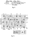
- Fig. 12 a time-frequency grid in a common OFDM/TDMA- and GSM-system is shown.
- Fig. 12 shows the time/frequency slot allocation for 3 OFDM/TDMA users and 1 GSM user.
- the OFDM/TDMA users use schemes as explained in relation to Fig. 11 with one OFDM/TDMA-timeslot mapped into one half of a GSM-timeslot. Two of the OFDM/TDMA-users transmit data with a normal data rate within the GSM-frequency channel of 200 kHz, whereas the third OFDM/TDMA user transmits data with a high data rate within 4 GSM frequency channels.
- the GSM-user uses a receiving GSM-timeslot 27, a transmitting GSM-timeslot 28, a receiving GSM-timeslot 29 and a transmitting GSM-timeslot 30. Between the transmitting GSM-timeslot 28 and the receiving GSM-timeslot 29, a slow frequency hopping takes place, and between the respective receiving and transmitting GSM-timeslots, a TDMA-process is carried out.
- the first OFDM/TDMA-user transmitting data with a normal data rate uses a first receiving OFDM/TDMA-timeslot 38, the transmitting OFDM/TDMA-timeslot 39, a receiving OFDM/TDMA-timeslot 40, a transmitting OFDM/TDMA-timeslot 41, a receiving OFDM/TDMA-timeslot 42, a transmitting OFDM/TDMA-timeslot 43 and a receiving OFDM/TDMA-timeslot 44.
- a TDMA-process is carried out, whereas between the respective transmitting timeslots and the next receiving timeslot, a slow frequency hopping takes place.
- a second user which uses a receiving OFDM/TDMA-timeslot 45, a transmitting OFDM/TDMA-timeslot 46, a receiving OFDM/TDMA timeslot 47, a transmitting OFDM/TDMA-timeslot 48, a receiving OFDM/TDMA-timeslot 48, a transmitting OFDM/TDMA-timeslot 50 and a receiving OFDM/TDMA timeslot 51.
- the third OFDM/TDMA user transmitting data with a high data rate uses a receiving OFDM/TDMA-timeslot 31, a transmitting OFDM/TDMA-timeslot 32, a receiving OFDM/TDMA-timeslot 33, a transmitting OFDM/TDMA-timeslot 34, a receiving OFDM/TDMA-timeslot 35, a transmitting OFDM/TDMA-timeslot 36 and a receiving OFDM/TDMA-timeslot 37. Also for the third OFDM/TDMA-user, a TDMA-processing is carried out between respective receiving and transmitting timeslots, and a slow frequency hopping is taking place between respective transmitting and receiving timeslots.
- a clock generating means 52 for a transmission and/or receiving apparatus which is capable of producing the necessary clocks both for a GSM-system and an OFDM/TDMA-system according to the present invention.
- the clock generating means 52 is based on the use of a common reference clock of 26 MHz, which is used in the GSM-system.
- the clock generating means 52 comprises an oscillator 53 which generates a 26 MHz clock.
- the clock generating means 52 further comprises a number of dividers and/or multipliers 54 to 70, which are selectively chosen for the used OFDM/TDMA-system.
- all possible dividers and multipliers are shown to produce the necessary clocks for all the embodiments described in the present application. However, the elements not necessary for the respectively chosen embodiment can be omitted.
- the output of the oscillator 53 is divided by 65 in a divider 54 and further divided by 2 in respective dividers 55 and 56 to produce a clock of 200 kHz for the GSM-system and the OFDM/TDMA-system, respectively.
- the 200 kHz clock is the basic clock for the mapping of 3 OFDM/TDMA timeslots into one GSM timeslot.
- the 200 kHz clock is the carrier and synthesizer reference clock.
- the output of the divider 54 is multiplied by 2 in a multiplier 57 and further divided by 3 in a divider 58 to generate a clock of 266.666 kHz which is the basic clock in the OFDM/TDMA-system for the mapping of one OFDM/TDMA-timeslot into one GSM timeslot and for the mapping of 4 OFDM/TDMA timeslots into one GSM timeslot.
- the output of the multiplier 57 is further multiplied with 4 in a multiplier 59 and then divided by 13 in a divider 60 to produce a clock of 246.154 kHz which is the basic clock in the OFDM/TDMA system for the mapping of one OFDM/TDMA timeslot in one GSM timeslot.
- the output of the oscillator 53 (26 MHz) is divided by 2 in a divider 61 and further divided by 48 in a divider 62 to produce a clock of 270.83 kHz, which is the bit clock in the GSM-system.
- the output of the divider 61 is further divided by 625 in a divider 63 and then divided by 4 in a divider 64 to produce a clock of 5.20 kHz, which is the necessary clock in the OFDM/TDMA-system for the mapping of 3 OFDM/TDMA timeslots into one GSM timeslot.
- the output of the divider 63 is further divided by 3 in a divider 65 to produce a clock of 6.933 kHz, which is a necessary clock for the OFDM/TDMA-system for the mapping of 4 OFDM/TDMA timeslots into one GSM timeslot.
- the output of the divider 65 is further divided by 2 in a divider 66 to produce a clock of 3.466 kHz, which is a necessary clock in the OFDM/TDMA-system for the mapping of 2 OFDM/TDMA timeslots into one GSM timeslot.
- the output of the divider 66 is further divided by 2 in a divider 67 to produce a clock of 1.733 kHz, which is a necessary clock in the OFDM/TDMA-system for the mapping of one OFDM/TDMA timeslot into one GSM timeslot.
- the clock of 1.733 kHz is also a necessary clock in the GSM-system for the GSM timeslots.
- the output of the divider 67 is further divided by 2 in a divider 68 to produce a clock of 866.66 Hz, which is the frame clock in an OFDM/TDMA-system, in which the operation mode is based on frames of a duration of 1,1538 ms (which is exactly 1 ⁇ 4 of the GSM frame length).
- the output of the divider 68 is further divided by 2 in a divider 69 to produce a clock of 433.33 Hz, which is the frame clock in an OFDM/TDMA-system, in which the operation mode is based on frames of a duration of 2,3077 ms (which is exactly 1 ⁇ 2 of the GSM frame length).
- the output of the divider 69 is further divided by 2 in a divider 70 to produce a clock of 216.66 Hz, which is the frame clock in an OFDM/TDMA-system in which the operation mode is based on frames of a duration of 4,6154 ms (which is exactly one GSM frame length).
- the clock of 216.66 Hz is also the frame clock in the GSM-system.
- the present invention comprises a burst (time-domain) and frequency slot allocation of a OFDM/TDMA-system, which is as far as possible backward compatible to the existing GSM-burst and frequency structure.
- the parameters of the OFDM/TDMA-system are chosen to support flexible band width services in the mobile environment.
- Fig. 14 shows a schematic diagram for explaining the allocation of the pilot symbols according to the present invention.
- a OFDM/TDMA-channel U 0 is shown.
- the channel U 0 shown in this example comprises six GSM-frequency-channels.
- the transmission band of the OFDM/TDMA system can be different from the GSM transmission band so that the subcarriers are allocated corresponding to the bandwidth of the GSM frequency channels.
- the OFDM/TDMA channels are allocated to the GSM frequency channels. Since the bandwidth of one GSM-frequency-channel is 200 kHz, the bandwidth of the channel U 0 in this case is 1,2 MHz.
- the bandwidth of the channel U 0 in this case is 1,2 MHz.
- FIG. 14 corresponds to the first embodiment explained above, in which the total number of subcarriers allocated to one GSM-frequency-channel is 48, so that two OFDM/TDMA-timeslots 101 and 102 are mapped into one GSM-timeslot, which has a duration of 5676,9 ⁇ s.
- the general structure of the OFDM/TDMA-channel U 0 in this example is shown in Fig. 14A.
- Fig. 14B subcarriers 1 allocated to the GSM-frequency-channel having a bandwidth of 200 kHz are shown in more detail. For the sake of clarity, only half of the number of 48 subcarriers, namely 24 subcarriers 1 are shown in Fig. 14B.
- the allocation of 48 subcarriers 1 to one GSM-frequency-channel has the consequence of two OFDM/TDMA-timeslots 101, 102 being mapped into one GSM-timeslot, as becomes clear from Fig. 14.
- the first OFDM/TDMA-timeslots 101 are shown in the left column of Fig. 14B and Fig. 14C, respectively, whereas the second OFDM/TDMA-timeslot 102 is shown in the right column of Fig. 14B and 14C, respectively.
- a pilot symbol 100' is allocated to every 6 th subcarrier 1.
- the subcarriers of the first OFDM/TDMA-timeslot 101 being modulated with pilot symbols 100 and the subcarriers 1 of the second OFDM/TDMA-timeslots being modulated with pilot symbols 100' are interlaced, so that the pilot symbols 100' of the second timeslot 102 have the respective middle frequency of the pilot symbols 100 of the timeslot 101.
- a pilot symbol 103, 103' is allocated to every 8 th subcarrier 1.
- the subcarriers 1 shown in Fig. 14B and 14C, which are not modulated with a pilot symbol 1, are modulated with data signals.
- the number of subcarriers within one GSM-timeslot is different from the number of subcarriers shown in Fig. 14 and also the number of OFDM/TDMA-timeslots comprised in one GSM-timeslot can be 1, 3 or 4.
- the interlacing scheme explained in Fig. 14 has to be applied correspondingly.
- the interleaving means 8 supplies a data stream, e. g. data signals d 0 d 1 ..., via the switch means 9b to the modulation means 9a.
- the switch means 9b interposes pilot symbols p 0 , p 1 , p 2 , p 3 ... generated in a pilot symbol generation means 9c, which can be for example a memory, in between the data of the data stream, so that a pilot symbol is allocated and modulated on every n-th subcarrier generated in the succeeding modulation means 9a.
- the switch means 9b interposes a pilot symbol between the data of the data stream so that a pilot symbol is allocated to every 6 th subcarrier generated the modulation means 9a. This case corresponds to the case shown in Fig. 14B.
- a receiving apparatus uses the transmitted pilot symbols to estimate a channel transfer function.
- the estimated channel transfer function is for example the channel attenuation.
- An exemplary explanation of the estimation of the channel attenuation in the estimation means 20b and the corresponding equalization of the received data signals in the equalization means 20c of the receiving apparatus according to the present invention is given relating to Fig. 16 and 17.
- Fig. 16 an example for a channel attenuation in case of an indoor environment is shown.
- the transmission system according to the present invention comprising a base station (receiving apparatus) and one or more mobile stations (transmission apparatus) in this case is for example used within a building, so that the moving velocity of the mobile stations is comparatively slow and multipath effects are not so important, so that the channel attenuation is a generally flat curve, as can be seen in Fig. 16. In this case, only a smaller number of pilot symbols is sufficient to allow the receiving apparatus to perform a correct estimation of the channel attenuation.
- the estimation means 20b compares the received pilot symbols with known pilot symbols, which are for example stored in a memory, and performs a time and/or frequency interpolation for the data modulated subcarriers.
- the example shown in Fig. 16 can thereby relate to the example shown in Fig. 14C, in which every n-th subcarrier carries a pilot symbol.
- the pilot symbols of the two adjacent OFDM/TDMA-timeslots 101 and 102 are interlaced.
- the estimation means 20b calculates an estimated attenuation value for each pilot symbol 100 of the first OFDM/TDMA-timeslot 101, and a channel attenuation value for the pilot symbols 100' of the second OFDM/TDMA-timeslot 102.
- the pilot symbols 100 and 100' are interlaced equidistantly. Then, the estimation means 19b estimates an interpolation curve connecting the calculated channel attenuation values for the power symbols 100 and 100' - The calculated or estimated channel attenuation curve is then used by the equalization means 20c for equalizing the transmitted data signals.
- Fig. 17 an channel attenuation curve is shown for an outdoor environment. As can be seen in Fig 17, the curve shows more variations than the curve for the indoor environment shown in Fig. 16. Therefore, more pilot symbols are necessary in this case to assure a correct equalization of the transmitted data signals. Therefore, and as can be seen in Fig. 17, more pilot symbols are allocated to the subcarriers in each GSM-frequency-channel. In this case, for example every 4 th subcarrier could be modulated with a pilot symbol. As can be seen from Figs. 16 and 17, the estimation means 20b estimates a channel transfer function, e. g. the channel attenuation, by detection the amplitude and the phase changes of the received known pilot symbol subcarriers.
- a channel transfer function e. g. the channel attenuation
- two-dimensional equalization-interpolation schemes e. g. time-domain interpolation using multiple adjacent OFDM/TDMA-timeslots and/or frequency domain interpolation using pilot symbol subcarriers are used.
- the position of the pilot symbols allocated equidistantly to corresponding subcarriers is, in the case of multiple adjacent OFDM/TDMA-timeslots, different for each OFDM/TDMA-timeslot.
Abstract
The present invention relates to a transmission method and a transmission apparatus for
transmitting signals on the basis of a OFDM/TDMA-system, wherein a plurality of
subcarriers being orthogonal to each other are allocated to a variable number of channels,
each channel containing a variable number of subcarriers depending on information to be
transmitted in said signals, wherein, for the transmission of said signals in a GSM-system
having a constant number of predetermined GSM-frequency channels and a constant
number of predetermined GSM-timeslots being grouped in GSM-frames, the number of
said subcarriers is allocated corresponding to the bandwidth of said GSM-frequency
channels, so that a multiple of one resulting OFDM/TDMA-timeslot matches with one or a
multiple of one GSM-timeslots, wherein a pilot symbol is allocated to every n-th
subcarrier in said GSM-frequency-channels, whereby n is an integer and >1, and wherein
said signals are transmitted.
The present invention also proposes a receiving method and a receiving apparatus for
receiving corresponding signals. Thereby, a reliable channel estimate and equalization can
be performed.
Description
The present invention relates to a transmission method and a transmission apparatus for
transmitting signals on the basis of an OFDM-TDMA-system according to claim 1 and
claim 5, respectively, and further to a receiving method and a receiving apparatus for
receiving signals transmitted by means of such a transmission method according to claim 9
and claim 12, respectively.
A transmission method and a transmission apparatus for transmitting signals on the basis of
a OFDM/TDMA-system are explained relating to figs. 1 - 4 of the present application. In
such a transmission method and apparatus, a plurality of subcarriers 1 being orthogonal to
each other can be allocated to a variable number of channels U0, U1 ... U9, each channel
U0, U1 ... U9 containing a variable number of subcarriers 1 depending on information to be
transmitted as shown in figs. 1 - 4. Fig. 1 shows a group of ten frequency channels U0, U1
... U9. Each frequency channel U0, U1 ... U9 can contain a variable number of subcarriers
depending on information to be transmitted, as shown for the channels U0 and U1 in Fig.
2. The channel U0 contains a plurality of subcarriers 1, and the channel U1 contains a
number of subcarriers 1 different from channel U0. In a transmission method and the
transmission apparatus for transmitting signals on the basis of a OFDM/TDMA-system, a
variable number of subcarriers 1 can be allocated to each channel depending on the amount
of information to be transmitted. The channel U0 shown in Fig. 2 contains 21 subcarriers
1, whereas the channel U1 shown in Fig. 2 contains only 10 subcarriers 1. Therefore, the
channel U0 can be transmitted by more than twice the transmission rate of the channel U0.
On the border of each channel U0, U1 ... U9, a single subcarrier having zero power is
placed as guard band 2 to minimize interference to users placed in the adjacent frequency
band or to fulfill certain spectrum masks. If the influence of an interference by the band in
the neighborhood is small, the guard band 2 need not to be provided, whereas, when the
influence is excessive, a plurality of guard bands 2 can be provided.
The subcarriers 1 are generated by orthogonal frequency division multiplex (OFDM)
processing. As shown in Fig. 3, W(f) indicates a wave form indicating an energy on the
frequency axis and B(Hz) indicates the distance between two adjacent subcarriers. The
OFDM processing provides for a multi-subcarrier-system, wherein the number of channels
which can be multiplexed is not limited by an interference from the other channels and can
be freely determined depending on the bandwidth to be allocated. By changing the number
of the subcarriers to be allocated to the different channels, it is possible to change the
transmission rate or to achieve a variable transmission rate. The subcarriers between the
respective channels can be easily separated by means of a filter, thereby making it possible
to prevent deterioration of S/N characteristics. Since the OFDM processing is used for the
multi-subcarrier modulation, a guard band S is not necessarily needed between different
channels, thereby achieving a very high spectral efficiency. Further on, because fast
Fourier transformation can be utilized, the necessary processing can be rapid and small.
Further on, the number of channels in each group of channels can be varied, as shown in
Fig. 4. In Fig. 4, a group of six channels U0, U1 ... U5 is shown. In a OFDM/TDMA-system,
the number of channels in a group of channels can be varied within the system
frequency band depending on information to be transferred.
In the known and standardized GSM-System, a type of single carrier frequency modulation
called GMSK is used. The frequency channels are constant and the spacing (bandwidth)
between adjacent frequency channels is 200 kHz. The number of FDMA-channels is 124
and a time division multiple access (TDMA) is used to support the number of parallel
connections. The TDMA scheme in the GSM-System is 8 GSM-timeslots within one time
frame. The GSM-timeslot length is 576,9 µs (15/26 ms), as is shown in Fig. 5. As can be
seen in Fig. 5, the transmitted GSM-timeslots are not fully occupied by the transmitted
burst to reduce interference from adjacent GSM-timeslots if the system is not perfectly
synchronized. The guard period is 8,25 bits, which corresponds to 30,5 µs. The guard
period is divided in two parts, wherein one of the parts is located at the beginning of the
GSM time slot, and the other part is located at the end of the GSM-timeslot.
A GSM time frame consists of 8 GSM time slots and has therefore a length of 4615,4 µs,
as is shown in Fig. 6. The GSM-system supports slow frequency hopping, which is
explained in Fig. 6. The shown GSM-timeslot 3 is a receiving timeslot. According to the
time division duplex (TDD)-system of the GSM-system, a corresponding transmission
GSM-timeslot 4 is transmitted some timeslots later. Further on, the GSM-system makes
use of the frequency division duplex (FDD)-system with 45 MHz between uplink and
downlink, so that the transmission GSM-timeslot 4 is transmitted in the corresponding
uplink frequency band, when the receiving GSM-timeslot 3 had been sent in the uplink
frequency band, or vice versa. The next succeeding receiving GSM-timeslot 5 is of course
transmitted in the same uplink or downlink frequency band as the preceding GSM-timeslot
3, but in a different frequency channel, according to the slow frequency hopping. The
frequency hopping improves, together with the interleaving procedure, the transmission of
the signals in view of the frequency and interference diversity. The usual interleaving
depth in the GSM-system is 36,923 ms corresponding to 8×8 GSM-timeslots.
When transmitting signals between a base station and one or more mobile stations, the
mobile channel introduces multipath distortion on the signaling wave forms. Both the
amplitude and phase are corrupted as the channel characteristics changes because of
movements of the mobile station. In order to perform a coherent detection of the
transmitted signals, reliable channel estimates are required. This can be obtained by
occasionally transmitting known data or so-called pilot symbols. The corresponding
receiving side interpolates the channel information derived from the pilot symbols to
obtain a channel estimate for equalizing the received data signal. The pilot symbol is
thereby known both by the transmitting and the receiving apparatus.
The object of the present invention is therefore to provide a transmission method and a
transmission apparatus for transmitting signals on the basis of an GSM compatible OFDM-TDMA-system
and further a receiving method and a receiving apparatus for receiving
such signals, which allow for a reliable channel estimation on the receiving side.
This object is achieved by a transmission method according to claim 1, a transmission
apparatus according to claim 5, a receiving method according to claim 9 and a receiving
apparatus according to claim 12. The above object is also achieved by a transmission
system according to claim 15.
Advantageous features of the present invention are defined in the respective subclaims.
The transmission method for transmitting signals on the basis of a OFDM/TDMA-system
comprises the steps of
wherein, for the transmission of said signal in a GSM-system having a constant number of predetermined GSM-frequency channels and a constant number of predetermined GSM-timeslots being grouped in GSM-frames, a number of said subcarriers is allocated corresponding to the bandwidth of said GSM-frequency channels, so that a multiple of one resulting OFDM/TDMA-timeslots matches with one or a multiple of one GSM-timeslot, wherein a pilot symbol is allocated to every n-th subcarrier, whereby n is an integer and n> 1, and
The transmission apparatus for transmitting signals on the basis of a OFDM/TDMA-system
according to the present invention comprises
In the presented transmission system, the signals are transmitted in or on the basis of an
OFDM/TDMA-system, which is backward compatible to the standardized GSM-system.
The transmission band of this OFDM/TDMA-system can be the same or can be different
from the known GSM frequency band. A respective number of subcarriers of the
OFDM/TDMA-system are allocated so that their bandwidth matches or corresponds to the
bandwidth or a multiple of the bandwidth of the GSM frequency channels. Signals formed
in an OFDM/TDMA system can in this way be transmitted and/or received also in an
GSM-system.
The allocation of pilot symbols to every n-th subcarrier according to the present invention
allows an accurate and reliable channel measurement and consequently a reliable
correction of the received data signals on the receiving side. In case that a multiple of one
OFDM/TDMA-timeslot matches with one GSM-timeslot, the pilot symbols in adjacent
OFDM/TDMA-timeslots are advantageously frequency interlaced in respect to each other.
Thereby, not only a frequency interpolation, but also a time interpolation of the channel
transfer function on the receiving side is enabled to assure a reliable correction of the
received data signals. The pilot symbols in adjacent OFDM/TDMA-timeslots can be
symmetrically interlaced, whereby one pilot symbol is allocated to a subcarrier in the
frequency middle between two respective pilot symbols of an adjacent OFDM/TDMA-timeslot.
Thereby, an optimized interpolation on the basis of the received pilot symbols for
estimating the channel transfer function on the receiving side can be performed.
In a further advantageous embodiment of the present invention, 48 of said subcarriers are
allocated corresponding to the bandwidth of said GSM-frequency channels, so said 2
OFDM/TDMA-timeslots match with 1 GSM-timeslot, whereby n = 6 or n = 8. By
choosing these parameters, the number of used pilot symbols is optimized. The use of pilot
symbols for a channel function estimation introduces an overhead to the transmitted
signals, which cannot be used for the transmission of data signals, and it is thus desirable
to keep the number of pilot symbols low. On the other hand, a high number of pilot
symbols is required on the receiving side to assure a reliable channel function estimate for
a correction of the received data signals. The presented parameters define an optimized
choice in view of these contradicting criteria. Further on, these parameters are chosen in
view of the use of the present invention in an indoor environment, in which the channel
transfer function, e. g. the channel attenuation, is a generally flat curve. In this case, only
a small number of pilot symbols is necessary for a usable estimation. In an outdoor
environment, however, a larger number of pilot symbols in each transmission channel, for
example an GSM-frequency channel is necessary to enable the estimation of a usable
channel transfer function. The reason is that in an outdoor environment, the channel
transfer function, e. g. the channel attenuation, can have large variations due to multipath
effects and a faster moving speed of the mobile stations. Therefore, it is necessary to tailor
the pilot symbols to each base station side and also to choose the number of transmitted
pilot symbols correspondingly. The parameters defmed in the subclaims 4 and 8 are
particularly useful in an indoor environment, in which the channel attenuation has a
generally flat curve and the moving speed of the mobile stations is comparatively low.
In the transmission apparatus and the transmission method, the number of subcarriers to be
allocated corresponding to the bandwidth of one GSM-frequency channel can be chosen,
so that several OFDM/TDMA-timeslots are mapped into one GSM-timeslot, or several
OFDM/TDMA-timeslots are mapped into several GSM-timeslots, e.g. eight GSM-timeslots
(one GSM-frame). In the OFDM/TDMA-system, the transformation of one or a
plurality of the subcarriers into the time domain results in a OFDM/TDMA-time burst.
According to the present invention, one OFDM/TDMA timeslot contains essentially one
OFDM/TDMA-time burst.
A very important consequence of the mapping of the OFDM/TDMA-timeslots into the
GSM-timeslots is that the same interleaving depth as in a standard GSM-system can be
obtained. A standard GSM-interleaving depth is 8×8 GSM-timeslots (approx. 36,923 ms).
In the present invention, one or more OFDM/TDMA-timeslots (e. g. two, four, ...) are
mapped into one GSM-timeslot. Therefore, the information units to be transmitted
according to the system of the present invention can be smaller than in the standard GSM-system.
This is advantageous in view of the interleaving depth. If, for example, two
OFDM/TDMA-timeslots are mapped into one GSM-timeslot, and 8 OFDM/TDMA-timeslots
form one frame (8-TDMA), an interleaving depth of 8 frames (same as GSM)
results in a total interleaving delay of 18,461 ms, which is half of the corresponding total
interleaving delay of 36,923 ms in the GSM-system. Therefore, the transmission of
information in a system according to the present invention can have a smaller overall delay
with the same interleaving (frequency and interference diversity. An interleaving depth of
16 frames (approx. 36,923ms) results in the same overall delay as in the standard GSM-system,
but is much more reliable in view of transmission problems (time-, frequency- and
interference diversity). For the transmission of speech signals, usually a smaller
interleaving delay is desired due to the real time requirements. For example, for the
transmission of speech signals interleaving depths smaller than 40 ms and short time-frames
(4-10 ms) are advantageous. For the transmission of data signals, the real time
requirements are not so important, so that a longer interleaving depth can be chosen to
improve the data transmission reliability.
Advantageously, the signals to be transmitted are interleaved with a total interleaving delay
corresponding to 8×8 GSM-timeslots. Alternatively, the signals to be transmitted are
interleaved with a total interleaving delay corresponding to 4×8 GSM-timeslots.
Further on, the allocating step can comprise the steps of generating a clock, modulating a
signal to be transmitted and producing said number of subcarriers according to said clock,
transforming said subcarriers into time range bursts, and generating said OFDM/TDMA-timeslots
by adding a guard time, a ramp time and an adaptation guard time to each of said
time range bursts.
Correspondingly, the allocation means can comprise clock generation means for generating
a clock, a modulation means for modulating a signal to be transmitted and producing said
number of subcarriers according to said clock, a transformation means for transforming
said subcarriers into time range bursts, and a timeslot generation means for generating said
OFDM/TDMA-timeslots by adding a guard time, a ramp time and an adaptation guard
time to each of said time range bursts.
According to further aspects advantageous, numbers of subcarriers to be allocated
corresponding to the bandwidth of said GSM-frequency channels are defined, so that the
resulting OFDM/TDMA-timeslots match well into one or a multiple of one GSM-timeslot.
In the following description, the OFDM/TDMA signals are formed and transmitted in a
GSM system. A number of OFDM/TDMA subcarriers is allocated to one or more GSM
frequency channels in the standardized GSM transmission band. The present invention is,
however, not limited to this example and the OFDM/TDMA transmission band can be
different from the GSM transmission band. In this case, the OFDM/TDMA frequency
channels are different from the GSM frequency channels. The subcarriers of the
OFDM/TDMA system, however, are allocated so that their bandwidth matches or
corresponds essentially to the bandwidth or a multiple of the bandwidth of the GSM
frequency channels, to assure the compatibility.
The present invention is further directed to a transmission system according to claim 16.
In the following detailed description, the present invention is explained by means of
preferred embodiments relating to the respective drawings, in which
The general features of an OFDM/TMDA-system have been explained above relating to
figs. 1 - 4. The general features of a GSM-system have been explained above relating to
the figures 5 and 6. According to the present invention, a number of subcarriers of a
OFDM/TDMA-system is allocated to each GSM-frequency channel so that a multiple of
one resulting OFDM/TDMA-timeslots matches with one ore a multiple of one GSM-timeslot.
The spacing between two adjacent GSM-frequency channels is 200 kHz, and the
length of a GSM-timeslot is 15/26 ms. According to the present invention, one GSM-frequency
channel is divided into a number of subcarriers. The number of subcarriers is
chosen, so that a multiple of one resulting OFDM/TDMA-timeslot fits well in one or a
multiple of one GSM-timeslot. A transformation of one subcarrier from the frequency
domain into the time domain results in an OFDM/TDMA-time burst, which builds the
largest part of a resulting OFDM/TDMA-timeslot. In Fig. 7, the basic structure of an
OFDM/TDMA-timeslot is shown. The basic structure of an OFDM/TDMA-timeslot
contains an OFDM/TDMA-time burst, whereby the length of the OFDM/TDMA-timeburst
TOFDM corresponds to the effective Modulation Period and depends on the
subcarrier-spacing (1/subcarrier-spacing). The subcarrier spacing depends thereby on the
number of subcarriers allocated to one GSM-frequency channel of 200 kHz. In front of the
OFDM/TDMA-time burst TOFDM, a guard time TG (pre-guard time) is located.
In Fig. 8, the detailed structure of an OFDM/TDMA-timeslot is shown. The length of the
OFDM/TDMA-timeslot corresponds to the modulation period and has a length of a in µs.
After the transformation of the subcarriers into the time domain, whereby the
OFDM/TDMA-timebursts are produced, a guard time consisting of a pre-guard time and a
post-guard time is added to the OFDM-TDMA-timebursts. The OFDM/TDMA-timebursts
correspond to the effective modulation period and have a length of b in µs. The length of
the pre-guard time located in front of the OFDM/TDMA-timebursts in c in µs and the
length of the post-guard time located behind the OFDM/TDMA-timebursts is e in µs.
Then, before transmitting, the time-domain signal is shaped to reduce spurious emissions.
Thereby, the ramp of the time domain signal is shaped according to a raised cosine
function, as shown in Fig. 8. As can be seen in Fig. 8, the ramp time in the front part and
the back part of the OFDM/TDMA-timeslot, respectively, has a length of d in µs and
overlaps partially with the pre-guard time and the post-guard time, respectively. The
length of the post-guard time can be 0 µs. At the beginning of the OFDM/TDMA-timeslot
there is located a pre-idle time in front of the ramp time and at the end of the
OFDM/TDMA-timeslot there is located a post-idle time behind the ramp time. The length
of the pre-idle time and the post-idle time is f in µs. Therefore, the resulting
OFDM/TDMA-timeslot is composed of the OFDM/TDMA-timeburst (effective
modulation period), the guard time consisting of the pre-guard time and the post- guard
time, the ramp times and the pre-idle time and the post-idle time. The length b of the
OFDM/TDMA-timeburst depends on the subcarrier spacing (b = 1/fscs), whereby fscsis
the subcarrier spacing in Hz. According to the present invention, the length a of one
OFDM/TDMA-timeslot can for example correspond to 1, 1/2, 1/3 or 1/4 GSM-timeslot.
In Fig. 9, the basic scheme of a transmission apparatus according to the present invention
is shown. Signals 6 to be transmitted are fed into a channel coding means 7. The channel
coded signals are fed into an interleaving means 8, where they are interleaved according to
a chosen interleaving depth, for example 8×8 OFDM/TDMA-frames or 16×8
OFDM/TDMA-frames.. In a switch means 9b, pilot symbols generated in a pilot symbol
generation means 9c are interposed and allocated to the data stream of the interleaved
signals coming from the interleaving means 8. The interleaved signals are fed into a
modulation means 9a, in which a OFDM processing is conducted to produce a chosen
number of subcarriers. The switch means 9b is set so that in each GSM-frequency channel
known pilot symbols are located or modulated on every n-th subcarrier in between the
subcarriers carrying and being modulated with data signals to be transferred. This part of
the transmission apparatus is shown in more detail in Fig. 15. The subcarriers are
transformed in an inverse discrete or fast Fourier transformation means 10 into the time
domain. In a timeslot formation means 11, the time domain bursts are provided with a
guard time TG, and the time bursts are shaped, for example with a raised cosine function.
The OFDM/TDMA-timeslots are then converted in a D/A-converter 12 from digital into
analog signals and then upconverted in a RF-upconversion means 13 - The thus processed
signals are then transmitted by an antenna 15. A clock generation means 14 provides the
interleaving means 8, the modulation means 9a, the switch means 9b, the inverse
discrete/fast Fourier transformation means 10 and the timeslot formation means 11 with
the necessary clock signals. The clock generation means 14 can contain a switching means
to change the clock depending on the required transmission system. For example, the
clock generating means 14 could, controlled by the switching means, provide the
modulation means 9a with different clock signals to produce different numbers of
subcarriers.
In Fig. 10, a basic scheme of a receiving apparatus according to the present invention is
shown. An antenna 15 receives transmitted signals, which are downconverted in a RF-downconversion
means 16. Then, the downconverted signals are digitized in a A/D-converter
17. The thus converted signals are transformed in a discrete/fast Fourier
transformation means 19 into the frequency range, whereby the discrete/fast Fourier
transformation means 19 is time and frequency synchronized by a time synchronization
means 18a and a frequency synchronization means 18b. The frequency domain signals
output by the discrete/fast Fourier transformation means 19 of the above-mentioned
subcarriers being modulated with data signals, signaling signals, pilot signals etc. Are
demodulated in a demodulation means 20a. An estimation means 20b receives the pilot
symbols within the resulting data stream. Thereby, the estimation means 20b of the
receiving apparatus is set corresponding to the switch means 9b and the pilot symbol
generation means 9c of the corresponding transmission apparatus. In other words, in the
transmission system of the present invention, the transmission apparatus and the receiving
apparatus work on the basis of respectively known pilot symbols and of a respectively
known pilot symbol modulation rate of the subcarriers in each GSM-frequency channel. If,
for example, the transmission apparatus is implemented in a mobile station and the
receiving apparatus is implemented in a base station of a wireless telecommunication
system, the mobile station and the base station respectively know the pilot symbols and
know, which respective subcarriers are carrying pilot symbols. The estimation means 20b
of the receiving apparatus compares the received pilot symbols to the known pilot
symbols, e. g. stored in a memory, and performs an estimation of a channel transfer
function, e. g. the channel attenuation, based on the known pilot symbol and further
performs a time and/or frequency interpolation to generate an estimated channel transfer
function. By means of the estimated channel transfer function, an equalization means 20c
equalizes the transmitted data symbols. Thereby, a reliable and correct equalization of the
transmitted data can be achieved, as will be explained in more detail relating to figs. 16
and 17. The equalized signals are de-interleaved in a de-interleaving means 21. The de-interleaved
signals are then channel decoded in a channel decoding means 22. The channel
decoded data 23 can then be further processed as required. The time synchronization
means 18a, the frequency synchronization means 18b, discrete Fourier transformation
means 19, the demodulation means 20a, the estimation means 20b, the equalization means
20c, and the de-interleaving means 21 are provided with the necessary clock signals by a
clock generating means 52.
In the following, advantageous combinations of subcarrier numbers and numbers of
OFDM/TDMA-timeslots to be mapped into one or more GSM-timeslots are presented as
preferred solutions for the backward compatibility of a OFDM/TDMA-system in a GSM-system.
Thereby, the used frequency slot serving as a basis for the backward compatibility
is 200 kHz, which corresponds to the bandwidth of the frequency channels of the GSM-system.
The number of the subcarriers is chosen to assure a backwards compatibility of a
OFDM/TMDA-system to the GSM-timeslot structure or GSM-frame structure. Thereby,
even multiple of one GSM-timeslot or one GSM-frame are subdivided into proper
designed OFDM/TDMA-timeslots resulting from the number of subcarriers. According to
the present invention it is further ensured that an interleaving utilizing a cross-interleaving
to enhance the time-frequency diversity and the GSM-backward compatibility is possible.
Also, realistic delays, for example for speech signals, and relaxed interleaving delay
constraints, for example for the transmission of data signals, are considered. The following
preferred embodiments are identified as the best solutions for an OFDM/TDMA-system to
be GSM-backward compatible in channel allocation (frequency) and time structure (GSM-timeslots
or GSM-frames).
In the following embodiment it is proposed to map 1, 2, 3 or 4 OFDM/TDMA-timeslots
into one GSM-timeslot. Thereby, the pre-guard time and post-guard time are optional but
advantageous.
In a 1st embodiment, the total number of subcarriers is 48, whereby one or more
subcarriers on the borders can be left unmodulated to reduce the interference to adjacent
frequency slots. The resulting subcarrier spacing is 200 kHz/48 = 4,166 kHz, which leads
to a OFDM/TDMA-time burst TOFDM of 48/200 kHz = 240 µs. The symbol duration (240
µs) is therefore very long compared to the GSM-symbol duration (range of µs), which has
the advantage to avoid inter-symbol interference due to the radio channel delay profile.
The guard time (pre-guard time and post-guard time) in the first embodiment is set to 30
µs, whereby it has to be noted that the guard time has to be set according to the expected
channel delay profile (multipath environment). The ramp time is set to 10 to 20 µs, so that
the total OFDM/TDMA-timeslot TS has a length of 280 to 290 µs. This fits very well into
½ of the basic GSM-timeslot of 576,923 µs. Therefore, in the 1st embodiment, two
OFDM/TDMA-timeslots are mapped into one GSM-timeslot with an adaptation time
guard, if necessary.
The basic clock is 240µs/64= 3,75µs. The guard time (pre- and post guard time) can be set
to 30µs (pre-guard: 22.5µs= 6 samples, post-guard: 7.5µs = 2 samples) and the ramp
time can be set to 15.0µs ( = 4 samples) which leads to a total symbol time of
(250µs/64)*(64+6+2+4) =285µs.
The preferred interleaving scheme in the first embodiment bases on an OFDM/TDMA-frame
length of 2,3077 ms, i. e. 8 OFDM/TDMA-timeslots TS. The preferred interleaving
depth is 8×8 OFDM/TDMA-frames (total interleaving delay 18,461 ms) or 16×8
OFDM/TDMA-frames (total interleaving delay 36,923 ms). Also an interleaving depth of
12×8 OFDM/TDMA-frames is possible (total interleaving delay 27,692 ms). An
interleaving depth of 8×8 OFDM/TDMA-frames therefore allows a data transmission with
the same interleaver design and performance as in standard GSM, whereas an interleaving
depth of 16*8 OFDM/TDMA-frames allows a data transmission with the same interleaving
delay as in the standard GSM system, but with much better performance (interleaving
gain).
In the 2nd embodiment, the total number of subcarriers is chosen to be 32, wherein one or
more subcarriers at the borders can be left unmodulated to reduce the interference to
adjacent frequency slots. The subcarrier spacing is 200kHz/32 = 6.25kHz, which leads to
a OFDM/TDMA-burst of 1/6.25kHz = 160µs. The guard time (pre- and post guard time)
can be set to 20µs and the ramp time can be set to 10.0µs, which leads to a total
OFDM/TDMA-timeslot of 190µs. 3 OFDM/TDMA-timeslots TS are mapped into one
GSM-timeslot with an adaptation time guard. In other words, one OFDM/TDMA-timeslot
TS is mapped into 1/3 of a GSM-timeslot.
The basic clock is set to 160µs/32 = 5µs. To be more precise, the guard time (pre- and
post guard time) can be set to 20µs (pre-guard: 15.0µs= 3samples, post-guard: 5µs = 1
sample) and the ramp time can be set to 10.0µs( = 2 samples) which leads to a total
symbol time of (160µs/32)*(32+3+1+2) = 190µs.
The preferred interleaving scheme for the 2nd embodiment bases on one OFDM/TDMA-frame
containing 6 OFDM/TDMA-timeslots mapped into 2 GSM-timeslots. The preferred
interleaving depth is 4×4 OFDM/TDMA-frames (total interleaving delay 18,461 ms) or
8×4 OFDM/TDMA-frames (total interleaving delay 36,923 ms). Also, the interleaving
depth can be set to 6×4 OFDM/TDMA-frames (total interleaving delay 27,692 ms).
In the 3rd embodiment, the total number of subcarriers is chosen to be 24, wherein one or
more subcarriers at the borders can be left unmodulated to reduce the interference to
adjacent frequency slots. The subcarrier spacing is 200kHz/24 = 8.33kHz, which leads to
an OFDM/TDMA-burst of 1/8.33kHz = 120µs. The guard time (pre- and post guard
time) can be set to 15µs and the ramp time can be set to 9µs, which leads to a total
OFDM/TDMA-timeslot of 144µs. 4 OFDM/TDMA-timeslots TS are mapped into one
GSM-timeslot with an adaptation time guard. The scheme according to the 3rd embodiment
is very advantageous for fast varying channel environments. In other words, one
OFDM/TDMA-timeslot TS is mapped into ¼ of one GSM-timeslot.
The basic clock is set to 120µs/32 = 3.75µs. To be more precise, the guard time (pre- and
post guard time) can be set to 15µs (pre-guard: 11.25µs= 3samples, post-guard: 3.75µs =
1 sample) and the ramp time can be set to 7.5µs ( = 2 samples) which leads to a total
symbol time of (120µs/32)*(32+3+1+2) = 142.5µs.
The preferred interleaving scheme for the 3rd embodiment bases on one OFDM/TDMA-frame
containing 4 OFDM/TDMA-timeslots mapped into 1 GSM-timeslot. The preferred
interleaving depth is 4×4 OFDM/TDMA-frames (total interleaving delay 18,461 ms) or
8×4 OFDM/TDMA-frames (total interleaving delay 36,923 ms). Also, the interleaving
depths cap be set to 6×4 OFDM/TDMA-frames (total interleaving delay 27,692 ms).
In the 4th embodiment, the total number of subcarriers is chosen to be 104, wherein one or
more subcarriers at the borders can be left unmodulated to reduce the interference to
adjacent frequency slots. The subcarrier spacing is 200kHz/104 = 1.923kHz, which leads
to a OFDM/TDMA-burst of 1/1.923kHz = 520µs. The guard time (pre- and post guard
time) can be set to 25µs and the ramp time can be set to 15µs, which leads to a total
OFDM/TDMA-timeslot of 560µs. One OFDM/TDMA-timeslot is mapped into one GSM
timeslot with an adaptation guard of 17µs.
The basic clock is set to 520µs/128 = 4.0625µs. To be more precise, the guard time (preand post guard time) can be set to 28.4375µs (pre-guard: 20.3125µs = 5samples, post-guard: 8.125µs = 2 sample) and the ramp time can be set to 12.1875µs ( = 3 samples) which leads to a total symbol time of (520µs/128)*(128+5+2+3) = 560.625µs.
The basic clock is set to 520µs/128 = 4.0625µs. To be more precise, the guard time (preand post guard time) can be set to 28.4375µs (pre-guard: 20.3125µs = 5samples, post-guard: 8.125µs = 2 sample) and the ramp time can be set to 12.1875µs ( = 3 samples) which leads to a total symbol time of (520µs/128)*(128+5+2+3) = 560.625µs.
The interleaving scheme is the same as for GSM (8 frames within the 8 TDMA).
In all the above described embodiments, the interleaving scheme can be dynamically
changed for various data rates. For applications with less severe delay requirements, e. g.
for data services or picture and video services, the interleaver schemes of the above
described embodiments can be enhanced to dramatically improve the time and frequency
diversity effect. However, to ensure GSM-compatibility, 2, 4 and 8 GSM-timeslots for the
mapping schemes utilizing 1 GSM-timeslot are preferred. For the mapping schemes using
one GSM-frame as a basic OFDM/TDMA-frame, multiples of 1,2 and 4 are preferred.
The above presented compatibility schemes allow the combined usage of OFDM/TDMA-and
GSM-systems with a minimum adaptation effort. Also, a GSM- to OFDM/TDMA-handover
and vice versa can be easily performed. The interoperation of the two systems is
described in one following example referring to figs. 11 and 12.
In Fig. 11, a principle OFDM/TDMA-frame consisting of 8 OFDM/TDMA-timeslots is
mapped into half GSM-timeslots, which results in a total of 16 OFDM/TDMA-timeslots
being mapped into 8 GSM-timeslots. In other words, 2 OFDM/TDMA-timeslots are
mapped into 1 GSM-timeslot. In Fig. 11, a subframe of 2,308 ms containing 8
OFDM/TDMA-timeslots is shown. A OFDM/TDMA-timeslot 24 is a timeslot for
receiving data, the OFDM/TDMA-timeslot 25 is a timeslot for transmitting data, and a
OFDM/TDMA-timeslot 26 is the next corresponding timeslot for receiving data in the next
subframe. Between two timeslots 25 and 26, a slow frequency hopping can occur. The
subframe length of 2,308 ms allows 16 subframes in 36,923 ms. This is important for the
interleaving means used according to the present invention. The interleaving means
spreads the data bits over 16 subframes, which gives a good robustness against
transmission errors using time, frequency and interference diversity, and the overall
interleaving delay is still only 36,92 ms. As explained above, a small interleaving delay is
important for speech connections due to the real time requirement. The interleaving of the
16 OFDM/TDMA-subframes corresponds exactly to the interleaving depth of 8×8 GSM-frames
having a length of 36,923 ms.
With the parameters explained above, the OFDM/TDMA-system can coexist with the
existing GSM-system and is backward compatible in timeslots, frequency and interleaving.
Furthermore, the systems can coexist in a common system with a common allocated
frequency range. One advantage of the present invention is that multiple timeslots and/or
multiple frequency slots can be allocated to one user to enhance the data rate. In Fig. 12, a
time-frequency grid in a common OFDM/TDMA- and GSM-system is shown. Fig. 12
shows the time/frequency slot allocation for 3 OFDM/TDMA users and 1 GSM user. The
OFDM/TDMA users use schemes as explained in relation to Fig. 11 with one
OFDM/TDMA-timeslot mapped into one half of a GSM-timeslot. Two of the
OFDM/TDMA-users transmit data with a normal data rate within the GSM-frequency
channel of 200 kHz, whereas the third OFDM/TDMA user transmits data with a high data
rate within 4 GSM frequency channels.
The GSM-user uses a receiving GSM-timeslot 27, a transmitting GSM-timeslot 28, a
receiving GSM-timeslot 29 and a transmitting GSM-timeslot 30. Between the transmitting
GSM-timeslot 28 and the receiving GSM-timeslot 29, a slow frequency hopping takes
place, and between the respective receiving and transmitting GSM-timeslots, a TDMA-process
is carried out. The first OFDM/TDMA-user transmitting data with a normal data
rate uses a first receiving OFDM/TDMA-timeslot 38, the transmitting OFDM/TDMA-timeslot
39, a receiving OFDM/TDMA-timeslot 40, a transmitting OFDM/TDMA-timeslot
41, a receiving OFDM/TDMA-timeslot 42, a transmitting OFDM/TDMA-timeslot
43 and a receiving OFDM/TDMA-timeslot 44. Between the respective receiving
and transmitting OFDM/TDMA-timeslots, a TDMA-process is carried out, whereas
between the respective transmitting timeslots and the next receiving timeslot, a slow
frequency hopping takes place. The same is true for a second user, which uses a receiving
OFDM/TDMA-timeslot 45, a transmitting OFDM/TDMA-timeslot 46, a receiving
OFDM/TDMA timeslot 47, a transmitting OFDM/TDMA-timeslot 48, a receiving
OFDM/TDMA-timeslot 48, a transmitting OFDM/TDMA-timeslot 50 and a receiving
OFDM/TDMA timeslot 51. The third OFDM/TDMA user transmitting data with a high
data rate uses a receiving OFDM/TDMA-timeslot 31, a transmitting OFDM/TDMA-timeslot
32, a receiving OFDM/TDMA-timeslot 33, a transmitting OFDM/TDMA-timeslot
34, a receiving OFDM/TDMA-timeslot 35, a transmitting OFDM/TDMA-timeslot
36 and a receiving OFDM/TDMA-timeslot 37. Also for the third OFDM/TDMA-user,
a TDMA-processing is carried out between respective receiving and transmitting
timeslots, and a slow frequency hopping is taking place between respective transmitting
and receiving timeslots.
In Fig. 13, a clock generating means 52 for a transmission and/or receiving apparatus is
shown which is capable of producing the necessary clocks both for a GSM-system and an
OFDM/TDMA-system according to the present invention. The clock generating means 52
is based on the use of a common reference clock of 26 MHz, which is used in the GSM-system.
The clock generating means 52 comprises an oscillator 53 which generates a 26
MHz clock. The clock generating means 52 further comprises a number of dividers and/or
multipliers 54 to 70, which are selectively chosen for the used OFDM/TDMA-system. In
Fig. 13, all possible dividers and multipliers are shown to produce the necessary clocks for
all the embodiments described in the present application. However, the elements not
necessary for the respectively chosen embodiment can be omitted.
The output of the oscillator 53 is divided by 65 in a divider 54 and further divided by 2 in
respective dividers 55 and 56 to produce a clock of 200 kHz for the GSM-system and the
OFDM/TDMA-system, respectively. In the OFDM/TDMA-system, the 200 kHz clock is
the basic clock for the mapping of 3 OFDM/TDMA timeslots into one GSM timeslot. In
the GSM-system, the 200 kHz clock is the carrier and synthesizer reference clock.
The output of the divider 54 is multiplied by 2 in a multiplier 57 and further divided by 3
in a divider 58 to generate a clock of 266.666 kHz which is the basic clock in the
OFDM/TDMA-system for the mapping of one OFDM/TDMA-timeslot into one GSM
timeslot and for the mapping of 4 OFDM/TDMA timeslots into one GSM timeslot. The
output of the multiplier 57 is further multiplied with 4 in a multiplier 59 and then divided
by 13 in a divider 60 to produce a clock of 246.154 kHz which is the basic clock in the
OFDM/TDMA system for the mapping of one OFDM/TDMA timeslot in one GSM
timeslot.
The output of the oscillator 53 (26 MHz) is divided by 2 in a divider 61 and further
divided by 48 in a divider 62 to produce a clock of 270.83 kHz, which is the bit clock in
the GSM-system. The output of the divider 61 is further divided by 625 in a divider 63
and then divided by 4 in a divider 64 to produce a clock of 5.20 kHz, which is the
necessary clock in the OFDM/TDMA-system for the mapping of 3 OFDM/TDMA
timeslots into one GSM timeslot.
The output of the divider 63 is further divided by 3 in a divider 65 to produce a clock of
6.933 kHz, which is a necessary clock for the OFDM/TDMA-system for the mapping of 4
OFDM/TDMA timeslots into one GSM timeslot. The output of the divider 65 is further
divided by 2 in a divider 66 to produce a clock of 3.466 kHz, which is a necessary clock
in the OFDM/TDMA-system for the mapping of 2 OFDM/TDMA timeslots into one GSM
timeslot. The output of the divider 66 is further divided by 2 in a divider 67 to produce a
clock of 1.733 kHz, which is a necessary clock in the OFDM/TDMA-system for the
mapping of one OFDM/TDMA timeslot into one GSM timeslot. The clock of 1.733 kHz
is also a necessary clock in the GSM-system for the GSM timeslots.
The output of the divider 67 is further divided by 2 in a divider 68 to produce a clock of
866.66 Hz, which is the frame clock in an OFDM/TDMA-system, in which the operation
mode is based on frames of a duration of 1,1538 ms (which is exactly ¼ of the GSM
frame length). The output of the divider 68 is further divided by 2 in a divider 69 to
produce a clock of 433.33 Hz, which is the frame clock in an OFDM/TDMA-system, in
which the operation mode is based on frames of a duration of 2,3077 ms (which is exactly
½ of the GSM frame length). The output of the divider 69 is further divided by 2 in a
divider 70 to produce a clock of 216.66 Hz, which is the frame clock in an
OFDM/TDMA-system in which the operation mode is based on frames of a duration of
4,6154 ms (which is exactly one GSM frame length). The clock of 216.66 Hz is also the
frame clock in the GSM-system.
Using the proposed division rates and clock multipliers all necessary clock signals for
generating the necessary OFDM/TDMA-timeslots and bursts can be easily generated. A
system not using all the proposed OFDM/TDMA-structures can be implemented omitting
the not-used branches in the shown clock tree. All the parameters (subcarrier number,
subcarrier spacing, mapping into GSM-timeslots, FFT resolution) have been specified to
be easily GSM compatible and can be derived from a common GSM clock oscillator.
The present invention comprises a burst (time-domain) and frequency slot allocation of a
OFDM/TDMA-system, which is as far as possible backward compatible to the existing
GSM-burst and frequency structure. The parameters of the OFDM/TDMA-system are
chosen to support flexible band width services in the mobile environment.
Fig. 14 shows a schematic diagram for explaining the allocation of the pilot symbols
according to the present invention. In Fig. 14, a OFDM/TDMA-channel U0 is shown. The
channel U0 shown in this example comprises six GSM-frequency-channels. As explained
above, the transmission band of the OFDM/TDMA system can be different from the GSM
transmission band so that the subcarriers are allocated corresponding to the bandwidth of
the GSM frequency channels. In the explained case, however, the OFDM/TDMA channels
are allocated to the GSM frequency channels. Since the bandwidth of one GSM-frequency-channel
is 200 kHz, the bandwidth of the channel U0 in this case is 1,2 MHz. The case
shown in Fig. 14 corresponds to the first embodiment explained above, in which the total
number of subcarriers allocated to one GSM-frequency-channel is 48, so that two
OFDM/TDMA- timeslots 101 and 102 are mapped into one GSM-timeslot, which has a
duration of 5676,9 µs. The general structure of the OFDM/TDMA-channel U0 in this
example is shown in Fig. 14A.
In Fig. 14B, subcarriers 1 allocated to the GSM-frequency-channel having a bandwidth of
200 kHz are shown in more detail. For the sake of clarity, only half of the number of 48
subcarriers, namely 24 subcarriers 1 are shown in Fig. 14B. The allocation of 48
subcarriers 1 to one GSM-frequency-channel has the consequence of two OFDM/TDMA- timeslots
101, 102 being mapped into one GSM-timeslot, as becomes clear from Fig. 14.
The first OFDM/TDMA-timeslots 101 are shown in the left column of Fig. 14B and Fig.
14C, respectively, whereas the second OFDM/TDMA-timeslot 102 is shown in the right
column of Fig. 14B and 14C, respectively.
In Fig. 14B, a pilot symbol 100' is allocated to every 6th subcarrier 1. Thereby, the
subcarriers of the first OFDM/TDMA-timeslot 101 being modulated with pilot symbols
100 and the subcarriers 1 of the second OFDM/TDMA-timeslots being modulated with
pilot symbols 100' are interlaced, so that the pilot symbols 100' of the second timeslot 102
have the respective middle frequency of the pilot symbols 100 of the timeslot 101. The
same is true for the example shown in Fig 14C, in which a pilot symbol 103, 103' is
allocated to every 8th subcarrier 1. The subcarriers 1 shown in Fig. 14B and 14C, which
are not modulated with a pilot symbol 1, are modulated with data signals. The example
shown in Fig. 14B has a pilot symbol density of 1/6 = 16,6%. The example shown in
Fig. 14C has a pilot symbol density of 1/8 = 12,5%.
It has to be noted, that in the case of the second, third and forth embodiment explained
above, the number of subcarriers within one GSM-timeslot is different from the number of
subcarriers shown in Fig. 14 and also the number of OFDM/TDMA-timeslots comprised
in one GSM-timeslot can be 1, 3 or 4. In the cases, in which 3 or 4 OFDM/TDMA-timeslots
are comprised in one GSM-timeslot, the interlacing scheme explained in Fig. 14
has to be applied correspondingly.
In Fig. 15, a portion of the block diagram shown in Fig. 9 is explained in more detail. The
interleaving means 8 supplies a data stream, e. g. data signals d0 d1 ..., via the switch
means 9b to the modulation means 9a. The switch means 9b interposes pilot symbols p0,
p1, p2, p3 ... generated in a pilot symbol generation means 9c, which can be for example a
memory, in between the data of the data stream, so that a pilot symbol is allocated and
modulated on every n-th subcarrier generated in the succeeding modulation means 9a. In
the example shown in Fig. 15, the switch means 9b interposes a pilot symbol between the
data of the data stream so that a pilot symbol is allocated to every 6th subcarrier generated
the modulation means 9a. This case corresponds to the case shown in Fig. 14B.
A receiving apparatus, an example of which is shown in Fig. 10, uses the transmitted pilot
symbols to estimate a channel transfer function. The estimated channel transfer function is
for example the channel attenuation. An exemplary explanation of the estimation of the
channel attenuation in the estimation means 20b and the corresponding equalization of the
received data signals in the equalization means 20c of the receiving apparatus according to
the present invention is given relating to Fig. 16 and 17.
In Fig. 16, an example for a channel attenuation in case of an indoor environment is
shown. The transmission system according to the present invention comprising a base
station (receiving apparatus) and one or more mobile stations (transmission apparatus) in
this case is for example used within a building, so that the moving velocity of the mobile
stations is comparatively slow and multipath effects are not so important, so that the
channel attenuation is a generally flat curve, as can be seen in Fig. 16. In this case, only a
smaller number of pilot symbols is sufficient to allow the receiving apparatus to perform a
correct estimation of the channel attenuation. The estimation means 20b compares the
received pilot symbols with known pilot symbols, which are for example stored in a
memory, and performs a time and/or frequency interpolation for the data modulated
subcarriers. The example shown in Fig. 16 can thereby relate to the example shown in
Fig. 14C, in which every n-th subcarrier carries a pilot symbol. In this case, the pilot
symbols of the two adjacent OFDM/TDMA- timeslots 101 and 102 are interlaced. Thus,
the estimation means 20b calculates an estimated attenuation value for each pilot symbol
100 of the first OFDM/TDMA-timeslot 101, and a channel attenuation value for the pilot
symbols 100' of the second OFDM/TDMA-timeslot 102. As can be seen in Fig. 16, the
pilot symbols 100 and 100' are interlaced equidistantly. Then, the estimation means 19b
estimates an interpolation curve connecting the calculated channel attenuation values for
the power symbols 100 and 100' - The calculated or estimated channel attenuation curve is
then used by the equalization means 20c for equalizing the transmitted data signals.
In Fig. 17, an channel attenuation curve is shown for an outdoor environment. As can be
seen in Fig 17, the curve shows more variations than the curve for the indoor
environment shown in Fig. 16. Therefore, more pilot symbols are necessary in this case to
assure a correct equalization of the transmitted data signals. Therefore, and as can be seen
in Fig. 17, more pilot symbols are allocated to the subcarriers in each GSM-frequency-channel.
In this case, for example every 4th subcarrier could be modulated with a pilot
symbol. As can be seen from Figs. 16 and 17, the estimation means 20b estimates a
channel transfer function, e. g. the channel attenuation, by detection the amplitude and the
phase changes of the received known pilot symbol subcarriers. Thereby, two-dimensional
equalization-interpolation schemes, e. g. time-domain interpolation using multiple adjacent
OFDM/TDMA-timeslots and/or frequency domain interpolation using pilot symbol
subcarriers are used. The position of the pilot symbols allocated equidistantly to
corresponding subcarriers is, in the case of multiple adjacent OFDM/TDMA-timeslots,
different for each OFDM/TDMA-timeslot.
Claims (15)
- Transmission method for transmitting signals on the basis of a OFDM/TDMA-system, comprising the steps ofallocating a plurality of subcarriers being orthogonal to each other to a variable number of channels U0, U1 ... U9, each channel containing a variable number of subcarriers (1) depending on information to be transmitted in said signals,
wherein, for the transmission of said signals in a GSM-system having a constant number of predetermined GSM-frequency-channels and a constant number of predetermined GSM-timeslots being grouped in GSM-frames, a number of said subcarriers (1) is allocated corresponding to the bandwidth of said GSM-frequency-channels, so that a multiple of one resulting OFDM/TDMA-timeslot (TS) matches with one or a multiple of one GSM-timeslot, wherein a pilot symbol is allocated to every n-th subcarrier, n being an integer and n>1, andtransmitting said signals. - Transmission method according to claim 1,
characterized in,that in case that a multiple of one resulting OFDM/TDMA-timeslot (TS) matches with one GSM-timeslot, the pilot symbols in adjacent OFMD/TDMA-timeslots are frequency interlaced in respect to each other. - Transmission method according to claim 2,
characterized in,that the pilot symbols in adjacent OFDM/TDMA-timeslots are symmetrically interlaced, whereby one pilot symbol is allocated to a subcarrier in the frequency middle between two respective pilots symbols of an adjacent OFDM/TDMA-timeslot. - Transmission method according to claim 1,2 or 3,
characterized in,that 48 of said subcarriers are allocated corresponding to the bandwidth of said GSM-frequency channels, so that 2 OFDM/TDMA-timeslots match with 1 GSM-timeslot, whereby n=6 or n=8. - Transmission apparatus for transmitting signals on the basis of a OFDM/TDMA-system comprisingallocation means for allocating a plurality of subcarriers being orthogonal to each other to a variable number of channels (U0, U1 ... U9), each channel containing a variable number of subcarriers (1) depending on information to be transmitted in said signals, wherein said allocation means, for the transmission of said signals in a GSM-system having a constant number of predetermined GSM-frequency-channels and a constant number of predetermined GSM-timeslots being grouped in GSM-frames, allocates a number of said subcarriers (1) corresponding to the bandwidth of said GSM-frequency-channels, so that a multiple of one resulting OFDM/TDMA-timeslot (TS) matches with one or a multiple of one GSM-timeslot, and for allocating a pilot symbol to every n-th subcarrier, n being an integer and n>1, andtransmission means for transmitting said signals.
- Transmission apparatus according to claim 5,
characterized by,that said allocation means, in case that a multiple of one resulting OFDM/TDMA-timeslot (TS) matches with one GSM-timeslot, allocates the pilot symbols in adjacent OFDM/TDMA-timeslots so that they are frequency interlaced in respect to each other. - Transmission method according to claim 6,
characterized by,that in said allocation means, the pilot symbols in adjacent OFDM/TDMA-timeslots are symmetrically interlaced, whereby one pilot symbol is allocated to a subcarrier in the frequency middle between two respective pilot symbols of an adjacent OFDM/TDMA-timeslot. - Transmission apparatus according to claim 5, 6 or 7,
characterized in,that in said allocation means, 48 of said subcarriers are allocated corresponding to the bandwidth of said GSM-frequency channels, so that 2 OFDM/TDMA-timeslots match with 1 GSM-timeslot, whereby n=6 or n=8.. - Receiving method for receiving signals transmitted by means of a transmission method according to one of the claims 1 to 4,
characterized by
the steps ofreceiving the transmitted signals,estimating a channel transfer function on the basis of the received pilot symbols,equalizing data symbols transmitted in said signals on the basis of the estimated transfer function. - Receiving method according to claim 9,
characterized inthat said estimating step a time and/or frequency interpolation on the basis of the received pilot symbols is performed to generate said estimated channel transfer function. - Receiving method according to claim 9 or 10,
characterized inthat said channel transfer function is the channel attenuation. - Receiving apparatus for receiving signals transmitted by means of a transmission method according to one of the claims 1 to 4,
characterized bya receiving means for receiving the transmitted signals,an estimation means for estimating a channel transfer function on the basis of the received pilot symbols,an equalization means for equalizing data symbols transmitted in said signals on the basis of the estimated transfer function. - Receiving apparatus according to claim 12,
characterized in,that said estimation means performs a time and/or frequency interpolation on the basis of the received pilot symbols to generate said estimated channel transfer functions - Receiving apparatus according to claim 12 or 13,
characterized in,that said channel transfer function is the channel attenuation. - Transmission system comprising at least one transmission apparatus according to one of the claims 5 to 8 and a receiving apparatus according to one of the claims 12 to 14.
Priority Applications (5)
| Application Number | Priority Date | Filing Date | Title |
|---|---|---|---|
| EP98103101A EP0938208A1 (en) | 1998-02-22 | 1998-02-22 | Multicarrier transmission, compatible with the existing GSM system |
| US09/253,666 US6545997B1 (en) | 1998-02-22 | 1999-02-19 | Transmission method and transmission apparatus for transmitting signals on the basis of a OFDM/TDMA-system with pilot symbols |
| KR1019990005810A KR19990072821A (en) | 1998-02-22 | 1999-02-22 | Transmission Method and Transmission Apparatus for Transmitting Signals on the Basis of a OFDM/TDMA-System with pilot symbols |
| JP11043763A JP2000068975A (en) | 1998-02-22 | 1999-02-22 | Transmission method/device and reception method/device |
| CN991023722A CN1218528C (en) | 1998-02-22 | 1999-02-23 | Method and apparatus for transmission of frequency-division mutiplying time-division multiple access system signals with pilot-frequency signs |
Applications Claiming Priority (1)
| Application Number | Priority Date | Filing Date | Title |
|---|---|---|---|
| EP98103101A EP0938208A1 (en) | 1998-02-22 | 1998-02-22 | Multicarrier transmission, compatible with the existing GSM system |
Publications (1)
| Publication Number | Publication Date |
|---|---|
| EP0938208A1 true EP0938208A1 (en) | 1999-08-25 |
Family
ID=8231462
Family Applications (1)
| Application Number | Title | Priority Date | Filing Date |
|---|---|---|---|
| EP98103101A Withdrawn EP0938208A1 (en) | 1998-02-22 | 1998-02-22 | Multicarrier transmission, compatible with the existing GSM system |
Country Status (5)
| Country | Link |
|---|---|
| US (1) | US6545997B1 (en) |
| EP (1) | EP0938208A1 (en) |
| JP (1) | JP2000068975A (en) |
| KR (1) | KR19990072821A (en) |
| CN (1) | CN1218528C (en) |
Cited By (29)
| Publication number | Priority date | Publication date | Assignee | Title |
|---|---|---|---|---|
| WO2001082544A2 (en) * | 2000-04-21 | 2001-11-01 | Atheros Communications, Inc. | Protocol for a communication system using overlaid signals and multi-carrier frequency communication |
| EP1170897A1 (en) * | 2000-07-05 | 2002-01-09 | Sony International (Europe) GmbH | Pilot pattern design for a STTD scheme in an OFDM system |
| WO2002009298A2 (en) * | 2000-07-24 | 2002-01-31 | Runcom Communications Ltd. | Wireless interactive system and method |
| EP1180866A1 (en) * | 2000-03-27 | 2002-02-20 | Matsushita Electric Industrial Co., Ltd. | Base station apparatus and radio communication method |
| EP1187387A1 (en) * | 2000-09-08 | 2002-03-13 | Alcatel | Multicarrier GSM receiver |
| EP1204217A1 (en) | 2000-11-03 | 2002-05-08 | Sony International (Europe) GmbH | Transmission power control scheme for OFDM communication links |
| WO2002041548A1 (en) * | 2000-11-17 | 2002-05-23 | Matsushita Electric Industrial Co., Ltd. | Ofdm communication device |
| GB2378860A (en) * | 2001-06-29 | 2003-02-19 | Sepura Ltd | Time slot allocation within a frame of a multicarrier TDMA system |
| WO2003036849A1 (en) * | 2001-09-28 | 2003-05-01 | Siemens Aktiengesellschaft | Speed-dependent multicarrier modulation |
| WO2004056022A2 (en) * | 2002-12-13 | 2004-07-01 | Electronics And Telecommunications Research Institute | Apparatus and method for signal constitution for downlink of ofdma-based cellular system |
| WO2005074217A1 (en) * | 2004-01-28 | 2005-08-11 | Qualcomm Incorporated | Time filtering for excess delay mitigation in ofdm systems |
| EP1771961A2 (en) * | 2004-07-29 | 2007-04-11 | QUALCOMM Incorporated | System and method for interleaving |
| EP1786220A1 (en) * | 2005-11-10 | 2007-05-16 | Research In Motion Limited | Notification of the allocation of communication resources in a multicarrier radio communication system |
| EP1786219A1 (en) * | 2005-11-10 | 2007-05-16 | Research In Motion Limited | Method and apparatus for allocating channels for data communication in a radio communication system |
| EP1786164A1 (en) | 2005-11-10 | 2007-05-16 | Research In Motion Limited | Method and apparatus for communicating data upon multiple radio carriers |
| EP1796410A1 (en) * | 2005-11-10 | 2007-06-13 | Research In Motion Limited | Method and apparatus for allocating communication resources to communicate data in a radio communication system |
| EP2066088A1 (en) * | 2004-05-04 | 2009-06-03 | Qualcomm Incorporated | Staggered Pilot Transmission For Channel Estimation And Time Tracking |
| EP1919152A3 (en) * | 2002-06-27 | 2009-07-08 | Nortel Networks Limited | Dual-mode shared OFDM methods/transmitters, receivers and systems |
| US7564823B2 (en) | 2005-11-10 | 2009-07-21 | Research In Motion Limited | Method and apparatus for communicating data upon multiple radio carriers |
| US7583640B2 (en) | 2005-11-10 | 2009-09-01 | Research In Motion Limited | Apparatus and method for providing notification of allocation of communication resources in a radio communication system |
| US7688797B2 (en) | 2002-08-29 | 2010-03-30 | Gigaset Communications Gmbh | Method and transmission device for transmission of data in a multi-carrier system |
| EP2234299A1 (en) * | 2001-08-27 | 2010-09-29 | Panasonic Corporation | Wireless communications apparatus and wireless communications method |
| US7885215B2 (en) | 2005-11-10 | 2011-02-08 | Research In Motion Limited | Method and apparatus for allocating communication resources to communicate data in a radio communication system |
| US8027399B2 (en) | 2004-01-21 | 2011-09-27 | Qualcomm Incorporated | Pilot transmission and channel estimation for an OFDM system with excess delay spread |
| US8391410B2 (en) | 2004-07-29 | 2013-03-05 | Qualcomm Incorporated | Methods and apparatus for configuring a pilot symbol in a wireless communication system |
| TWI399937B (en) * | 2007-07-25 | 2013-06-21 | Qualcomm Inc | System and method for frequency diversity |
| US9042212B2 (en) | 2005-07-29 | 2015-05-26 | Qualcomm Incorporated | Method and apparatus for communicating network identifiers in a communication system |
| US9246728B2 (en) | 2004-07-29 | 2016-01-26 | Qualcomm Incorporated | System and method for frequency diversity |
| EP3429119A1 (en) * | 2003-08-12 | 2019-01-16 | Godo Kaisha IP Bridge 1 | Radio communication apparatus and pilot symbol transmission method |
Families Citing this family (123)
| Publication number | Priority date | Publication date | Assignee | Title |
|---|---|---|---|---|
| EP1705852B1 (en) | 1999-01-08 | 2010-02-10 | Sony Deutschland Gmbh | Synchronisation symbol structure for OFDM system |
| US6539063B1 (en) * | 1999-02-18 | 2003-03-25 | Ibiquity Digital Corporation | System and method for recovering symbol timing offset and carrier frequency error in an OFDM digital audio broadcast system |
| US7079506B1 (en) * | 1999-05-28 | 2006-07-18 | Nokia Corporation | Enhancements to the 3-carrier compact solution for IS-136HS |
| JP3437513B2 (en) * | 1999-11-30 | 2003-08-18 | 松下電器産業株式会社 | Multi-carrier communication device and multi-carrier communication method |
| JP4409743B2 (en) * | 2000-02-25 | 2010-02-03 | パナソニック株式会社 | Wireless communication apparatus and wireless communication system |
| WO2001082500A2 (en) | 2000-04-22 | 2001-11-01 | Atheros Communications, Inc. | Methods for controlling shared access to wireless transmission systems and increasing throughput of the same |
| US6289000B1 (en) * | 2000-05-19 | 2001-09-11 | Intellon Corporation | Frame control encoder/decoder for robust OFDM frame transmissions |
| JP2002009733A (en) * | 2000-06-27 | 2002-01-11 | Hitachi Kokusai Electric Inc | Transmission apparatus employing orthogonal frequency division multiplexing modulation system |
| EP1178640B1 (en) * | 2000-08-01 | 2006-05-24 | Sony Deutschland GmbH | Device and method for channel estimating an OFDM system |
| EP2031788B1 (en) * | 2000-08-24 | 2011-11-30 | Sony Deutschland Gmbh | Communication device for receiving and transmitting OFDM signals in a wireless communication system |
| US6721569B1 (en) * | 2000-09-29 | 2004-04-13 | Nortel Networks Limited | Dynamic sub-carrier assignment in OFDM systems |
| US7072315B1 (en) | 2000-10-10 | 2006-07-04 | Adaptix, Inc. | Medium access control for orthogonal frequency-division multiple-access (OFDMA) cellular networks |
| US6870808B1 (en) | 2000-10-18 | 2005-03-22 | Adaptix, Inc. | Channel allocation in broadband orthogonal frequency-division multiple-access/space-division multiple-access networks |
| US6804223B2 (en) * | 2000-11-30 | 2004-10-12 | Ipr Licensing, Inc. | Reverse link pilot integrated with block codes |
| JP4529281B2 (en) | 2000-12-08 | 2010-08-25 | ソニー株式会社 | Transmitting apparatus, receiving apparatus, and communication system |
| JP4213466B2 (en) | 2000-12-15 | 2009-01-21 | アダプティックス インコーポレイテッド | Multi-carrier communication with adaptive cluster configuration and switching |
| JP4031707B2 (en) * | 2000-12-15 | 2008-01-09 | アダプティックス インコーポレイテッド | Multi-carrier communication with group-based subcarrier allocation |
| US6947748B2 (en) | 2000-12-15 | 2005-09-20 | Adaptix, Inc. | OFDMA with adaptive subcarrier-cluster configuration and selective loading |
| US7164669B2 (en) * | 2001-01-19 | 2007-01-16 | Adaptix, Inc. | Multi-carrier communication with time division multiplexing and carrier-selective loading |
| US6810236B2 (en) * | 2001-05-14 | 2004-10-26 | Interdigital Technology Corporation | Dynamic channel quality measurement procedure for adaptive modulation and coding techniques |
| US6975583B2 (en) * | 2001-05-14 | 2005-12-13 | Intel Corporation | Technique for continuous OFDM modulation |
| FR2825551B1 (en) * | 2001-05-30 | 2003-09-19 | Wavecom Sa | METHOD FOR ESTIMATING THE TRANSFER FUNCTION OF A TRANSMISSION CHANNEL OF A MULTI-CARRIER SIGNAL, METHOD OF RECEIVING A DIGITAL SIGNAL, AND RECEIVER OF A MULTI-CARRIER SIGNAL THEREOF |
| US6758836B2 (en) * | 2002-02-07 | 2004-07-06 | C. R. Bard, Inc. | Split tip dialysis catheter |
| JP3898533B2 (en) * | 2002-03-11 | 2007-03-28 | シャープ株式会社 | Wireless communication system |
| JP2003309533A (en) * | 2002-04-17 | 2003-10-31 | Matsushita Electric Ind Co Ltd | Wireless transmitter, wireless receiver, and method thereof |
| US8194770B2 (en) * | 2002-08-27 | 2012-06-05 | Qualcomm Incorporated | Coded MIMO systems with selective channel inversion applied per eigenmode |
| US20040081131A1 (en) * | 2002-10-25 | 2004-04-29 | Walton Jay Rod | OFDM communication system with multiple OFDM symbol sizes |
| US7002900B2 (en) | 2002-10-25 | 2006-02-21 | Qualcomm Incorporated | Transmit diversity processing for a multi-antenna communication system |
| US8208364B2 (en) * | 2002-10-25 | 2012-06-26 | Qualcomm Incorporated | MIMO system with multiple spatial multiplexing modes |
| CN102014100B (en) * | 2002-10-25 | 2013-03-06 | 高通股份有限公司 | Data detection and demodulation for wireless communication systems |
| US7324429B2 (en) | 2002-10-25 | 2008-01-29 | Qualcomm, Incorporated | Multi-mode terminal in a wireless MIMO system |
| US8170513B2 (en) * | 2002-10-25 | 2012-05-01 | Qualcomm Incorporated | Data detection and demodulation for wireless communication systems |
| US8134976B2 (en) | 2002-10-25 | 2012-03-13 | Qualcomm Incorporated | Channel calibration for a time division duplexed communication system |
| US7986742B2 (en) * | 2002-10-25 | 2011-07-26 | Qualcomm Incorporated | Pilots for MIMO communication system |
| US8320301B2 (en) | 2002-10-25 | 2012-11-27 | Qualcomm Incorporated | MIMO WLAN system |
| US8570988B2 (en) | 2002-10-25 | 2013-10-29 | Qualcomm Incorporated | Channel calibration for a time division duplexed communication system |
| US8218609B2 (en) * | 2002-10-25 | 2012-07-10 | Qualcomm Incorporated | Closed-loop rate control for a multi-channel communication system |
| US8169944B2 (en) | 2002-10-25 | 2012-05-01 | Qualcomm Incorporated | Random access for wireless multiple-access communication systems |
| US7042857B2 (en) | 2002-10-29 | 2006-05-09 | Qualcom, Incorporated | Uplink pilot and signaling transmission in wireless communication systems |
| US7039001B2 (en) * | 2002-10-29 | 2006-05-02 | Qualcomm, Incorporated | Channel estimation for OFDM communication systems |
| JP4009641B2 (en) * | 2002-11-20 | 2007-11-21 | 株式会社エヌ・ティ・ティ・ドコモ | COMMUNICATION SYSTEM, COMMUNICATION METHOD, TRANSMISSION DEVICE, RECEPTION DEVICE, AND CONTROL PROGRAM |
| US6873614B2 (en) * | 2002-12-19 | 2005-03-29 | Motorola, Inc. | Digital communication system having improved color code capability |
| US20040152479A1 (en) * | 2003-01-31 | 2004-08-05 | Rainbolt Bradley J. | Data channel procedure for systems employing frequency diversity |
| US7177297B2 (en) * | 2003-05-12 | 2007-02-13 | Qualcomm Incorporated | Fast frequency hopping with a code division multiplexed pilot in an OFDMA system |
| KR100539947B1 (en) * | 2003-06-18 | 2005-12-28 | 삼성전자주식회사 | Apparatus and method for transmitting/receiving pilot pattern for distinguish base station in communication using orthogonal frequency division multiplexing scheme |
| CN1567765B (en) * | 2003-06-23 | 2010-06-16 | 北京三星通信技术研究有限公司 | New pilot frequency transmitting and allocating method of OFDMA system |
| EP1639844B1 (en) * | 2003-06-23 | 2015-10-21 | Spreadtrum Communications Inc. | Time interleaved multiple standard single radio system apparatus and method |
| CN1567764B (en) * | 2003-06-23 | 2010-05-12 | 北京三星通信技术研究有限公司 | New sub-channel generating and allocating method of multi-user OFDMA system |
| ATE533245T1 (en) * | 2003-08-28 | 2011-11-15 | Motorola Solutions Inc | OFDM CHANNEL ESTIMATION AND TRACKING USING MULTIPLE TRANSMIT ANTENNAS |
| US7221680B2 (en) * | 2003-09-02 | 2007-05-22 | Qualcomm Incorporated | Multiplexing and transmission of multiple data streams in a wireless multi-carrier communication system |
| US8599764B2 (en) * | 2003-09-02 | 2013-12-03 | Qualcomm Incorporated | Transmission of overhead information for reception of multiple data streams |
| US8477809B2 (en) * | 2003-09-02 | 2013-07-02 | Qualcomm Incorporated | Systems and methods for generalized slot-to-interlace mapping |
| US8509051B2 (en) * | 2003-09-02 | 2013-08-13 | Qualcomm Incorporated | Multiplexing and transmission of multiple data streams in a wireless multi-carrier communication system |
| JP2005110228A (en) * | 2003-09-10 | 2005-04-21 | Matsushita Electric Ind Co Ltd | Secure communication method, transmitting device, and receiving device |
| US8526412B2 (en) * | 2003-10-24 | 2013-09-03 | Qualcomm Incorporated | Frequency division multiplexing of multiple data streams in a wireless multi-carrier communication system |
| US9473269B2 (en) | 2003-12-01 | 2016-10-18 | Qualcomm Incorporated | Method and apparatus for providing an efficient control channel structure in a wireless communication system |
| US8204149B2 (en) | 2003-12-17 | 2012-06-19 | Qualcomm Incorporated | Spatial spreading in a multi-antenna communication system |
| US8611283B2 (en) * | 2004-01-28 | 2013-12-17 | Qualcomm Incorporated | Method and apparatus of using a single channel to provide acknowledgement and assignment messages |
| KR100640516B1 (en) | 2004-02-27 | 2006-10-30 | 삼성전자주식회사 | Method and apparatus for transmitting channel quality information in orthogonal frequency division multiple communication system |
| JP4701163B2 (en) | 2004-03-05 | 2011-06-15 | 株式会社エヌ・ティ・ティ・ドコモ | Frequency channel assignment system, base station, control station, inter-system common control apparatus, frequency channel assignment method and control method |
| KR100651454B1 (en) * | 2004-03-05 | 2006-11-29 | 삼성전자주식회사 | Method for allocating a subchannel in an orthogonal frequency division multiple access cellular communication system |
| KR100620914B1 (en) * | 2004-04-07 | 2006-09-13 | 삼성전자주식회사 | Apparatus and method for switching between amc mode and diversity mode in broadband wireless communication system |
| US8923785B2 (en) | 2004-05-07 | 2014-12-30 | Qualcomm Incorporated | Continuous beamforming for a MIMO-OFDM system |
| KR100877318B1 (en) * | 2004-05-18 | 2009-01-09 | 콸콤 인코포레이티드 | Slot-to-interlace and interlace-to-slot converters for an ofdm system |
| US7516029B2 (en) | 2004-06-09 | 2009-04-07 | Rambus, Inc. | Communication channel calibration using feedback |
| KR101053610B1 (en) * | 2004-06-25 | 2011-08-03 | 엘지전자 주식회사 | Radio resource allocation method of OPDM / OPDM system |
| US8027243B2 (en) * | 2004-06-25 | 2011-09-27 | Lg Electronics Inc. | Allocation of radio resource in orthogonal frequency division multiplexing system |
| US7978649B2 (en) * | 2004-07-15 | 2011-07-12 | Qualcomm, Incorporated | Unified MIMO transmission and reception |
| US8891349B2 (en) | 2004-07-23 | 2014-11-18 | Qualcomm Incorporated | Method of optimizing portions of a frame |
| US7382842B2 (en) * | 2004-08-02 | 2008-06-03 | Beceem Communications Inc. | Method and system for performing channel estimation in a multiple antenna block transmission system |
| US7573851B2 (en) | 2004-12-07 | 2009-08-11 | Adaptix, Inc. | Method and system for switching antenna and channel assignments in broadband wireless networks |
| US8831115B2 (en) | 2004-12-22 | 2014-09-09 | Qualcomm Incorporated | MC-CDMA multiplexing in an orthogonal uplink |
| US8238923B2 (en) * | 2004-12-22 | 2012-08-07 | Qualcomm Incorporated | Method of using shared resources in a communication system |
| US8009551B2 (en) * | 2004-12-22 | 2011-08-30 | Qualcomm Incorporated | Initial pilot frequency selection |
| US7453849B2 (en) * | 2004-12-22 | 2008-11-18 | Qualcomm Incorporated | Method of implicit deassignment of resources |
| CN101099319B (en) * | 2005-01-14 | 2011-10-05 | 富士通株式会社 | Frequency division communication system |
| JP4635642B2 (en) * | 2005-02-25 | 2011-02-23 | ソニー株式会社 | Wireless communication apparatus and wireless communication method |
| EP1856873A1 (en) * | 2005-03-10 | 2007-11-21 | QUALCOMM Incorporated | Timing synchronization and channel estimation at a transition between local and wide area waveforms using a designated tdm pilot |
| ES2421782T3 (en) * | 2005-04-29 | 2013-09-05 | Sony Deutschland Gmbh | Transmission device, reception device and communication method for an OFDM communications system with new preamble structure |
| US7466749B2 (en) | 2005-05-12 | 2008-12-16 | Qualcomm Incorporated | Rate selection with margin sharing |
| KR100933157B1 (en) * | 2005-05-13 | 2009-12-21 | 삼성전자주식회사 | Method and device for configuring physical channel index in orthogonal frequency division multiple access system |
| WO2006121302A1 (en) * | 2005-05-13 | 2006-11-16 | Samsung Electronics Co., Ltd. | Method and apparatus for indexing physical channels in an ofdma system |
| US7957327B2 (en) * | 2005-05-18 | 2011-06-07 | Qualcomm Incorporated | Efficient support for TDD beamforming via constrained hopping and on-demand pilot |
| JP4869724B2 (en) * | 2005-06-14 | 2012-02-08 | 株式会社エヌ・ティ・ティ・ドコモ | Transmission device, transmission method, reception device, and reception method |
| US8358714B2 (en) | 2005-06-16 | 2013-01-22 | Qualcomm Incorporated | Coding and modulation for multiple data streams in a communication system |
| US8730877B2 (en) * | 2005-06-16 | 2014-05-20 | Qualcomm Incorporated | Pilot and data transmission in a quasi-orthogonal single-carrier frequency division multiple access system |
| US7822007B2 (en) * | 2005-08-23 | 2010-10-26 | Electronics And Telecommunications Research Institute | Transmitter in FDMA communication system and method for configuring pilot channel |
| KR100975719B1 (en) * | 2005-09-07 | 2010-08-12 | 삼성전자주식회사 | Method for assigning sub channel in a communication system using orthogonal frequency division multiple access scheme |
| KR101026156B1 (en) * | 2005-09-27 | 2011-04-05 | 노키아 코포레이션 | Pilot structure for multicarrier transmissions |
| EP1943746B1 (en) * | 2005-10-07 | 2019-06-05 | Nokia Technologies Oy | Apparatus, method and computer program product providing common pilot channel for soft frequency reuse |
| DE602005007041D1 (en) * | 2005-11-10 | 2008-07-03 | Research In Motion Ltd | A method and apparatus for communicating resource allocation by using a temporary channel set identifier |
| US8335207B2 (en) * | 2005-12-30 | 2012-12-18 | Samsung Electronics Co., Ltd. | Link mobility tracking and its application to mobile ad hoc networks |
| WO2007082035A2 (en) * | 2006-01-11 | 2007-07-19 | Qualcomm Incorporated | Choosing parameters in a peer-to-peer communications system |
| US8811369B2 (en) * | 2006-01-11 | 2014-08-19 | Qualcomm Incorporated | Methods and apparatus for supporting multiple communications modes of operation |
| EP2793410B1 (en) * | 2006-01-18 | 2015-12-09 | Ntt Docomo, Inc. | Base station, communication terminal, transmission method and reception method |
| CN101405950B (en) * | 2006-01-18 | 2013-09-11 | 株式会社Ntt都科摩 | Base station, communication terminal, transmission method and reception method |
| US8027306B2 (en) * | 2006-02-17 | 2011-09-27 | Lg Electronics Inc. | Miscellaneous improvements on the HRPD system |
| US8543070B2 (en) | 2006-04-24 | 2013-09-24 | Qualcomm Incorporated | Reduced complexity beam-steered MIMO OFDM system |
| CN102882628B (en) * | 2006-04-25 | 2016-12-21 | 日本电气株式会社 | Wireless transmission device, wireless communication system and pilot signal transmission method |
| US8023574B2 (en) * | 2006-05-05 | 2011-09-20 | Intel Corporation | Method and apparatus to support scalability in a multicarrier network |
| CN101940024A (en) * | 2006-08-08 | 2011-01-05 | 北电网络有限公司 | Method and system for wireless communication in multiple operating environments |
| US8509323B2 (en) * | 2006-08-22 | 2013-08-13 | Motorola Mobility Llc | Resource allocation including a DC sub-carrier in a wireless communication system |
| JP5092350B2 (en) * | 2006-10-26 | 2012-12-05 | 富士通株式会社 | Pilot signal transmission method and mobile communication system |
| WO2008065901A1 (en) * | 2006-11-29 | 2008-06-05 | Kyocera Corporation | Radio communication system, radio communication device, and radio communication method |
| EP2120377A1 (en) * | 2007-02-09 | 2009-11-18 | Sharp Kabushiki Kaisha | Ofdm transmitter and ofdm receiver |
| ES2797393T3 (en) | 2007-05-01 | 2020-12-02 | Qualcomm Inc | Position location for wireless communication systems |
| US8514988B2 (en) * | 2007-05-18 | 2013-08-20 | Qualcomm Incorporated | Enhanced pilot signal receiver |
| US8412227B2 (en) | 2007-05-18 | 2013-04-02 | Qualcomm Incorporated | Positioning using enhanced pilot signal |
| US20090175210A1 (en) * | 2007-07-26 | 2009-07-09 | Qualcomm Incorporated | Multiplexing and transmission of multiple data streams in a wireless multi-carrier communication system |
| EP2210383A4 (en) * | 2007-10-17 | 2012-09-12 | Zte Usa Inc | Ofdm/ofdma frame structure for communication systems |
| US8369301B2 (en) * | 2007-10-17 | 2013-02-05 | Zte (Usa) Inc. | OFDM/OFDMA frame structure for communication systems |
| KR101533457B1 (en) * | 2007-11-29 | 2015-07-03 | 엘지전자 주식회사 | Method for transmitting control signal in wireless communication system |
| KR101541910B1 (en) * | 2007-11-29 | 2015-08-04 | 엘지전자 주식회사 | Method for transmitting ACK/NACK signal in wireless communication system |
| KR101467570B1 (en) * | 2007-11-29 | 2014-12-01 | 엘지전자 주식회사 | Method for allocating radio resource in wireless communication system |
| KR101397248B1 (en) * | 2007-12-16 | 2014-05-20 | 엘지전자 주식회사 | Method for transmitting data in multiple antenna system |
| US8595501B2 (en) * | 2008-05-09 | 2013-11-26 | Qualcomm Incorporated | Network helper for authentication between a token and verifiers |
| JP2010074398A (en) * | 2008-09-17 | 2010-04-02 | Ntt Docomo Inc | Ofdm modulation/demodulation method, ofdm modulator, ofdm demodulator, and ofdm modulation/demodulation system |
| JP5555763B2 (en) | 2009-03-17 | 2014-07-23 | インターデイジタル パテント ホールディングス インコーポレイテッド | Method and apparatus for power control of sounding reference signal (SRS) transmission |
| JP4495243B2 (en) * | 2009-07-27 | 2010-06-30 | 株式会社エヌ・ティ・ティ・ドコモ | OFDM modulation / demodulation method, OFDM modulator and OFDM demodulator |
| JP4586933B2 (en) * | 2009-12-14 | 2010-11-24 | ソニー株式会社 | Transmitting apparatus, receiving apparatus, and communication system |
| KR20170127577A (en) | 2010-02-12 | 2017-11-21 | 인터디지탈 패튼 홀딩스, 인크 | Method and apparatus for enhancing cell-edge user performance and signaling radio link failure conditions via downlink cooperative component carriers |
| TWI462514B (en) * | 2011-09-29 | 2014-11-21 | Inst Information Industry | Time division duplex orthogonal frequency division multiplexing distributed antenna system, base station and remote access unit |
| WO2013116127A1 (en) * | 2012-01-30 | 2013-08-08 | Zte (Usa) Inc. | Method and system for physical downlink control channel multiplexing |
Citations (9)
| Publication number | Priority date | Publication date | Assignee | Title |
|---|---|---|---|---|
| EP0441731A1 (en) * | 1990-02-06 | 1991-08-14 | ETAT FRANCAIS représenté par le Ministre des P.T.T. (Centre National d'Etudes des Télécommunications-CNET) | Method of data broadcasting using time-frequency interleaving and coherent demodulation |
| EP0562868A2 (en) * | 1992-03-27 | 1993-09-29 | WI-LAN Inc | Method and apparatus for multiple access between transceivers in wireless communication using OFDM spread spectrum |
| EP0734132A2 (en) * | 1995-03-23 | 1996-09-25 | Kabushiki Kaisha Toshiba | Signal structure for multicarrier modulation, which reduces the overhead requirement |
| EP0752779A2 (en) * | 1995-07-03 | 1997-01-08 | Nokia Mobile Phones Ltd. | Distribution of phase of references in a multicarrier system |
| WO1997001256A1 (en) * | 1995-06-22 | 1997-01-09 | Telefonaktiebolaget Lm Ericsson (Publ) | Adaptive channel allocation in a frequency division multiplexed system |
| EP0760564A2 (en) * | 1995-08-28 | 1997-03-05 | Telia Ab | Random access in multicarrier systems |
| EP0786890A2 (en) * | 1996-01-29 | 1997-07-30 | Sony Corporation | Resource allocation in a multi-user, multicarrier mobile radio system |
| EP0810746A2 (en) * | 1996-05-27 | 1997-12-03 | Sony Corporation | Transmission apparatus using a multi-carrier signal with allocation of subcarriers |
| EP0825741A2 (en) * | 1996-08-23 | 1998-02-25 | Sony Corporation | Communication method and apparatus |
Family Cites Families (2)
| Publication number | Priority date | Publication date | Assignee | Title |
|---|---|---|---|---|
| US5684795A (en) * | 1996-01-30 | 1997-11-04 | Motorola, Inc. | Method and apparatus for controlling a fractional-N synthesizer in a time division multiple access system |
| DE69838807T2 (en) * | 1998-02-18 | 2008-10-30 | Sony Deutschland Gmbh | Mapping of multicarrier signals in GSM time slots |
-
1998
- 1998-02-22 EP EP98103101A patent/EP0938208A1/en not_active Withdrawn
-
1999
- 1999-02-19 US US09/253,666 patent/US6545997B1/en not_active Expired - Fee Related
- 1999-02-22 KR KR1019990005810A patent/KR19990072821A/en not_active Application Discontinuation
- 1999-02-22 JP JP11043763A patent/JP2000068975A/en not_active Withdrawn
- 1999-02-23 CN CN991023722A patent/CN1218528C/en not_active Expired - Fee Related
Patent Citations (9)
| Publication number | Priority date | Publication date | Assignee | Title |
|---|---|---|---|---|
| EP0441731A1 (en) * | 1990-02-06 | 1991-08-14 | ETAT FRANCAIS représenté par le Ministre des P.T.T. (Centre National d'Etudes des Télécommunications-CNET) | Method of data broadcasting using time-frequency interleaving and coherent demodulation |
| EP0562868A2 (en) * | 1992-03-27 | 1993-09-29 | WI-LAN Inc | Method and apparatus for multiple access between transceivers in wireless communication using OFDM spread spectrum |
| EP0734132A2 (en) * | 1995-03-23 | 1996-09-25 | Kabushiki Kaisha Toshiba | Signal structure for multicarrier modulation, which reduces the overhead requirement |
| WO1997001256A1 (en) * | 1995-06-22 | 1997-01-09 | Telefonaktiebolaget Lm Ericsson (Publ) | Adaptive channel allocation in a frequency division multiplexed system |
| EP0752779A2 (en) * | 1995-07-03 | 1997-01-08 | Nokia Mobile Phones Ltd. | Distribution of phase of references in a multicarrier system |
| EP0760564A2 (en) * | 1995-08-28 | 1997-03-05 | Telia Ab | Random access in multicarrier systems |
| EP0786890A2 (en) * | 1996-01-29 | 1997-07-30 | Sony Corporation | Resource allocation in a multi-user, multicarrier mobile radio system |
| EP0810746A2 (en) * | 1996-05-27 | 1997-12-03 | Sony Corporation | Transmission apparatus using a multi-carrier signal with allocation of subcarriers |
| EP0825741A2 (en) * | 1996-08-23 | 1998-02-25 | Sony Corporation | Communication method and apparatus |
Non-Patent Citations (1)
| Title |
|---|
| LARSSON ET AL.: "Mixed traffic in multi carrier system", 1996 IEEE VEHICULAR TECHNOLOGY CONFERENCE, 28 April 1996 (1996-04-28) - 1 May 1996 (1996-05-01), NEW YORK, US, pages 1259 - 1263, XP000593147 * |
Cited By (66)
| Publication number | Priority date | Publication date | Assignee | Title |
|---|---|---|---|---|
| EP1180866A4 (en) * | 2000-03-27 | 2002-12-18 | Matsushita Electric Ind Co Ltd | Base station apparatus and radio communication method |
| EP1180866A1 (en) * | 2000-03-27 | 2002-02-20 | Matsushita Electric Industrial Co., Ltd. | Base station apparatus and radio communication method |
| WO2001082544A3 (en) * | 2000-04-21 | 2002-03-14 | Atheros Comm Inc | Protocol for a communication system using overlaid signals and multi-carrier frequency communication |
| WO2001082544A2 (en) * | 2000-04-21 | 2001-11-01 | Atheros Communications, Inc. | Protocol for a communication system using overlaid signals and multi-carrier frequency communication |
| US9369323B2 (en) | 2000-07-05 | 2016-06-14 | Sony Deutschland Gmbh | Pilot pattern design for a STTD scheme in an OFDM system |
| EP1170897A1 (en) * | 2000-07-05 | 2002-01-09 | Sony International (Europe) GmbH | Pilot pattern design for a STTD scheme in an OFDM system |
| US7948863B2 (en) | 2000-07-05 | 2011-05-24 | Sony Deutschland Gmbh | Pilot pattern design for a STTD scheme in an OFDM system |
| US7664009B2 (en) | 2000-07-05 | 2010-02-16 | Sony Deutschland Gmbh | Pilot pattern design for a STTD scheme in an OFDM system |
| US7660228B2 (en) | 2000-07-05 | 2010-02-09 | Sony Deutschland Gmbh | Pilot pattern design for an OFDM system |
| US7646700B2 (en) | 2000-07-05 | 2010-01-12 | Sony Deutschland Gmbh | Pilot pattern design for an OFDM system |
| US8483039B2 (en) | 2000-07-05 | 2013-07-09 | Sony Deutschland Gmbh | Pilot pattern design for a STTD scheme in an OFDM system |
| US7746759B2 (en) | 2000-07-05 | 2010-06-29 | Sony Deutschland Gmbh | Pilot pattern design for an OFDM system |
| US8532133B2 (en) | 2000-07-05 | 2013-09-10 | Sony Deutschland Gmbh | Pilot pattern design for a STTD scheme in an OFDM system |
| US8582417B2 (en) | 2000-07-05 | 2013-11-12 | Sony Deutschland Gmbh | Pilot pattern design for a STTD scheme in an OFDM system |
| US10291454B2 (en) | 2000-07-05 | 2019-05-14 | Wi-Fi One, Llc | Pilot pattern design for a STTD scheme in an OFDM system |
| US8953632B2 (en) | 2000-07-05 | 2015-02-10 | Sony Deutschland Gmbh | Pilot pattern design for a STTD scheme in an OFDM system |
| US9843467B2 (en) | 2000-07-05 | 2017-12-12 | Sony Deutschland Gmbh | Pilot pattern design for a STTD scheme in an OFDM system |
| US9596113B2 (en) | 2000-07-05 | 2017-03-14 | Sony Deutschland Gmbh | Pilot pattern design for a STTD scheme in an OFDM system |
| US7885175B2 (en) | 2000-07-05 | 2011-02-08 | Sony Deutschland Gmbh | Pilot pattern design for an OFDM system |
| US7221645B2 (en) | 2000-07-05 | 2007-05-22 | Sony Deutschland Gmbh | Pilot pattern design for a STTD scheme in an OFDM system |
| WO2002009298A2 (en) * | 2000-07-24 | 2002-01-31 | Runcom Communications Ltd. | Wireless interactive system and method |
| WO2002009298A3 (en) * | 2000-07-24 | 2002-05-02 | Runcom Comm Ltd | Wireless interactive system and method |
| EP1187387A1 (en) * | 2000-09-08 | 2002-03-13 | Alcatel | Multicarrier GSM receiver |
| EP1204217A1 (en) | 2000-11-03 | 2002-05-08 | Sony International (Europe) GmbH | Transmission power control scheme for OFDM communication links |
| WO2002041548A1 (en) * | 2000-11-17 | 2002-05-23 | Matsushita Electric Industrial Co., Ltd. | Ofdm communication device |
| GB2378860A (en) * | 2001-06-29 | 2003-02-19 | Sepura Ltd | Time slot allocation within a frame of a multicarrier TDMA system |
| EP2278742A2 (en) * | 2001-08-27 | 2011-01-26 | Panasonic Corporation | Apparatus and method for wireless transmission |
| EP2234299A1 (en) * | 2001-08-27 | 2010-09-29 | Panasonic Corporation | Wireless communications apparatus and wireless communications method |
| EP2278740A2 (en) * | 2001-08-27 | 2011-01-26 | Panasonic Corporation | Apparatus and method for wireless reception |
| EP2278741A2 (en) * | 2001-08-27 | 2011-01-26 | Panasonic Corporation | Apparatus and method for wireless reception |
| WO2003036849A1 (en) * | 2001-09-28 | 2003-05-01 | Siemens Aktiengesellschaft | Speed-dependent multicarrier modulation |
| EP1919152A3 (en) * | 2002-06-27 | 2009-07-08 | Nortel Networks Limited | Dual-mode shared OFDM methods/transmitters, receivers and systems |
| US7688797B2 (en) | 2002-08-29 | 2010-03-30 | Gigaset Communications Gmbh | Method and transmission device for transmission of data in a multi-carrier system |
| WO2004056022A3 (en) * | 2002-12-13 | 2005-05-06 | Korea Electronics Telecomm | Apparatus and method for signal constitution for downlink of ofdma-based cellular system |
| US7460466B2 (en) | 2002-12-13 | 2008-12-02 | Electronics And Telecommunications Research Institute | Apparatus and method for signal constitution for downlink of OFDMA-based cellular system |
| USRE45498E1 (en) | 2002-12-13 | 2015-04-28 | Electronics And Telecommunications Research Institute | Apparatus and method for signal constitution for downlink of OFDMA-based cellular system |
| WO2004056022A2 (en) * | 2002-12-13 | 2004-07-01 | Electronics And Telecommunications Research Institute | Apparatus and method for signal constitution for downlink of ofdma-based cellular system |
| EP3429119A1 (en) * | 2003-08-12 | 2019-01-16 | Godo Kaisha IP Bridge 1 | Radio communication apparatus and pilot symbol transmission method |
| CN101040503B (en) * | 2004-01-21 | 2013-08-14 | 高通股份有限公司 | Pilot transmission and channel estimation for an OFDM system with excess delay spread |
| US8537908B2 (en) | 2004-01-21 | 2013-09-17 | Qualcomm Incorporated | Pilot transmission and channel estimation for an OFDM system with excess delay spread |
| US8027399B2 (en) | 2004-01-21 | 2011-09-27 | Qualcomm Incorporated | Pilot transmission and channel estimation for an OFDM system with excess delay spread |
| WO2005074217A1 (en) * | 2004-01-28 | 2005-08-11 | Qualcomm Incorporated | Time filtering for excess delay mitigation in ofdm systems |
| AU2005208658B2 (en) * | 2004-01-28 | 2009-02-05 | Qualcomm Incorporated | Time filtering for excess delay mitigation in OFDM systems |
| CN1939017B (en) * | 2004-01-28 | 2010-09-01 | 高通股份有限公司 | Time filtering for excess delay mitigation in OFDM systems |
| US8553822B2 (en) | 2004-01-28 | 2013-10-08 | Qualcomm Incorporated | Time filtering for excess delay mitigation in OFDM systems |
| US7907593B2 (en) | 2004-05-04 | 2011-03-15 | Qualcomm Incorporated | Staggered pilot transmission for channel estimation and time tracking |
| EP2066088A1 (en) * | 2004-05-04 | 2009-06-03 | Qualcomm Incorporated | Staggered Pilot Transmission For Channel Estimation And Time Tracking |
| EP2512058A1 (en) * | 2004-07-29 | 2012-10-17 | Qualcomm Incorporated | Method and apparatus for frequency diversity |
| US9003243B2 (en) | 2004-07-29 | 2015-04-07 | Qualcomm Incorporated | System and method for modulation diversity |
| EP1771961A2 (en) * | 2004-07-29 | 2007-04-11 | QUALCOMM Incorporated | System and method for interleaving |
| US9246728B2 (en) | 2004-07-29 | 2016-01-26 | Qualcomm Incorporated | System and method for frequency diversity |
| US8391410B2 (en) | 2004-07-29 | 2013-03-05 | Qualcomm Incorporated | Methods and apparatus for configuring a pilot symbol in a wireless communication system |
| US9391751B2 (en) | 2005-07-29 | 2016-07-12 | Qualcomm Incorporated | System and method for frequency diversity |
| US9042212B2 (en) | 2005-07-29 | 2015-05-26 | Qualcomm Incorporated | Method and apparatus for communicating network identifiers in a communication system |
| US7583640B2 (en) | 2005-11-10 | 2009-09-01 | Research In Motion Limited | Apparatus and method for providing notification of allocation of communication resources in a radio communication system |
| CN1964572B (en) * | 2005-11-10 | 2010-04-14 | 捷讯研究有限公司 | Method and apparatus for allocating channels for data communication in a radio communication system |
| EP2068595A1 (en) * | 2005-11-10 | 2009-06-10 | Research In Motion Limited | Notification of the allocation of communication resources in a multicarrier radio communication system |
| EP1796410A1 (en) * | 2005-11-10 | 2007-06-13 | Research In Motion Limited | Method and apparatus for allocating communication resources to communicate data in a radio communication system |
| US8254948B2 (en) | 2005-11-10 | 2012-08-28 | Research In Motion Limited | Method and apparatus for allocating communication resources to communicate data in a radio communication system |
| US8649319B2 (en) | 2005-11-10 | 2014-02-11 | Blackberry Limited | Method and apparatus for allocating communication resources to communicate data in a radio communication system |
| EP1786219A1 (en) * | 2005-11-10 | 2007-05-16 | Research In Motion Limited | Method and apparatus for allocating channels for data communication in a radio communication system |
| EP1786164A1 (en) | 2005-11-10 | 2007-05-16 | Research In Motion Limited | Method and apparatus for communicating data upon multiple radio carriers |
| EP1786220A1 (en) * | 2005-11-10 | 2007-05-16 | Research In Motion Limited | Notification of the allocation of communication resources in a multicarrier radio communication system |
| US7564823B2 (en) | 2005-11-10 | 2009-07-21 | Research In Motion Limited | Method and apparatus for communicating data upon multiple radio carriers |
| US7885215B2 (en) | 2005-11-10 | 2011-02-08 | Research In Motion Limited | Method and apparatus for allocating communication resources to communicate data in a radio communication system |
| TWI399937B (en) * | 2007-07-25 | 2013-06-21 | Qualcomm Inc | System and method for frequency diversity |
Also Published As
| Publication number | Publication date |
|---|---|
| CN1218528C (en) | 2005-09-07 |
| CN1234661A (en) | 1999-11-10 |
| JP2000068975A (en) | 2000-03-03 |
| KR19990072821A (en) | 1999-09-27 |
| US6545997B1 (en) | 2003-04-08 |
Similar Documents
| Publication | Publication Date | Title |
|---|---|---|
| US6545997B1 (en) | Transmission method and transmission apparatus for transmitting signals on the basis of a OFDM/TDMA-system with pilot symbols | |
| EP0915586B1 (en) | Multicarrier transmission, compatible with the existing GSM system | |
| US10841141B2 (en) | Pilot design for OFDM systems with four transmit antennas | |
| EP2213018B1 (en) | Random access cyclic prefix dimensioning in wireless networks | |
| US9154281B2 (en) | Scattered pilot pattern and channel estimation method for MIMO-OFDM systems | |
| KR100956042B1 (en) | Constrained hopping in wireless communication systems | |
| JP5062852B2 (en) | Pilot signal transmission method | |
| KR100969780B1 (en) | Apparatus and method for transmitting/receiving pilot signal in an orthogonal frequency division multiplexing communication system | |
| KR101454531B1 (en) | Improved orthogonal frequency-division multiplexing (ofdm) communication slot structures and methods | |
| US20050099939A1 (en) | Apparatus and method for transmitting/receiving pilot signals in an OFDM communication system | |
| EP0938193A1 (en) | Header structure for TDD systems | |
| US8284653B2 (en) | User signal transmitting and receiving method, apparatus and system in OFDMA system | |
| WO2009143860A1 (en) | Method and apparatus for providing pilot signals in ofdm frames |
Legal Events
| Date | Code | Title | Description |
|---|---|---|---|
| PUAI | Public reference made under article 153(3) epc to a published international application that has entered the european phase |
Free format text: ORIGINAL CODE: 0009012 |
|
| AK | Designated contracting states |
Kind code of ref document: A1 Designated state(s): DE FI FR GB IT NL SE |
|
| AX | Request for extension of the european patent |
Free format text: AL;LT;LV;MK;RO;SI |
|
| 17P | Request for examination filed |
Effective date: 20000112 |
|
| AKX | Designation fees paid |
Free format text: DE FI FR GB IT NL SE |
|
| STAA | Information on the status of an ep patent application or granted ep patent |
Free format text: STATUS: THE APPLICATION HAS BEEN WITHDRAWN |
|
| RAP1 | Party data changed (applicant data changed or rights of an application transferred) |
Owner name: SONY INTERNATIONAL (EUROPE) GMBH |
|
| 18W | Application withdrawn |
Effective date: 20040223 |