KR20170127577A - Method and apparatus for enhancing cell-edge user performance and signaling radio link failure conditions via downlink cooperative component carriers - Google Patents
Method and apparatus for enhancing cell-edge user performance and signaling radio link failure conditions via downlink cooperative component carriers Download PDFInfo
- Publication number
- KR20170127577A KR20170127577A KR1020177032646A KR20177032646A KR20170127577A KR 20170127577 A KR20170127577 A KR 20170127577A KR 1020177032646 A KR1020177032646 A KR 1020177032646A KR 20177032646 A KR20177032646 A KR 20177032646A KR 20170127577 A KR20170127577 A KR 20170127577A
- Authority
- KR
- South Korea
- Prior art keywords
- wtru
- site
- enb
- power
- sites
- Prior art date
Links
- 238000000034 method Methods 0.000 title claims abstract description 63
- 239000000969 carrier Substances 0.000 title claims abstract description 39
- 230000011664 signaling Effects 0.000 title description 41
- 230000002708 enhancing effect Effects 0.000 title 1
- 238000004891 communication Methods 0.000 claims abstract description 56
- 241000760358 Enodes Species 0.000 claims description 16
- 210000004027 cell Anatomy 0.000 description 141
- 230000005540 biological transmission Effects 0.000 description 94
- 101000741965 Homo sapiens Inactive tyrosine-protein kinase PRAG1 Proteins 0.000 description 22
- 102100038659 Inactive tyrosine-protein kinase PRAG1 Human genes 0.000 description 22
- 238000005259 measurement Methods 0.000 description 21
- 238000001514 detection method Methods 0.000 description 17
- 230000007246 mechanism Effects 0.000 description 16
- 238000000926 separation method Methods 0.000 description 14
- 238000005516 engineering process Methods 0.000 description 12
- 230000006870 function Effects 0.000 description 12
- 230000015654 memory Effects 0.000 description 12
- 238000007726 management method Methods 0.000 description 9
- 238000013459 approach Methods 0.000 description 8
- 238000012544 monitoring process Methods 0.000 description 8
- 238000012545 processing Methods 0.000 description 8
- 230000001413 cellular effect Effects 0.000 description 7
- 230000005641 tunneling Effects 0.000 description 7
- 230000009849 deactivation Effects 0.000 description 6
- 230000004913 activation Effects 0.000 description 5
- 230000008859 change Effects 0.000 description 5
- 230000002776 aggregation Effects 0.000 description 4
- 238000004220 aggregation Methods 0.000 description 4
- 230000008901 benefit Effects 0.000 description 4
- 238000004422 calculation algorithm Methods 0.000 description 4
- 238000005457 optimization Methods 0.000 description 4
- 238000012384 transportation and delivery Methods 0.000 description 4
- 241000700159 Rattus Species 0.000 description 3
- 230000003044 adaptive effect Effects 0.000 description 3
- 230000015556 catabolic process Effects 0.000 description 3
- 125000004122 cyclic group Chemical group 0.000 description 3
- 238000006731 degradation reaction Methods 0.000 description 3
- 230000000694 effects Effects 0.000 description 3
- 230000006872 improvement Effects 0.000 description 3
- 230000008569 process Effects 0.000 description 3
- 238000013468 resource allocation Methods 0.000 description 3
- 230000001360 synchronised effect Effects 0.000 description 3
- 230000006399 behavior Effects 0.000 description 2
- 230000001186 cumulative effect Effects 0.000 description 2
- 230000003247 decreasing effect Effects 0.000 description 2
- 230000001419 dependent effect Effects 0.000 description 2
- 238000010586 diagram Methods 0.000 description 2
- 238000009826 distribution Methods 0.000 description 2
- 238000005315 distribution function Methods 0.000 description 2
- 238000001914 filtration Methods 0.000 description 2
- 230000007774 longterm Effects 0.000 description 2
- 238000010295 mobile communication Methods 0.000 description 2
- 230000004048 modification Effects 0.000 description 2
- 238000012986 modification Methods 0.000 description 2
- 230000003287 optical effect Effects 0.000 description 2
- 230000000737 periodic effect Effects 0.000 description 2
- 238000010926 purge Methods 0.000 description 2
- 238000011084 recovery Methods 0.000 description 2
- 230000003595 spectral effect Effects 0.000 description 2
- 238000001228 spectrum Methods 0.000 description 2
- 238000003860 storage Methods 0.000 description 2
- 238000012546 transfer Methods 0.000 description 2
- 230000007704 transition Effects 0.000 description 2
- 230000001960 triggered effect Effects 0.000 description 2
- 101100465000 Mus musculus Prag1 gene Proteins 0.000 description 1
- 210000004460 N cell Anatomy 0.000 description 1
- 238000009825 accumulation Methods 0.000 description 1
- 239000000654 additive Substances 0.000 description 1
- 230000000996 additive effect Effects 0.000 description 1
- 238000004873 anchoring Methods 0.000 description 1
- 230000003139 buffering effect Effects 0.000 description 1
- 238000004364 calculation method Methods 0.000 description 1
- 238000004590 computer program Methods 0.000 description 1
- 230000002068 genetic effect Effects 0.000 description 1
- GVVPGTZRZFNKDS-JXMROGBWSA-N geranyl diphosphate Chemical compound CC(C)=CCC\C(C)=C\CO[P@](O)(=O)OP(O)(O)=O GVVPGTZRZFNKDS-JXMROGBWSA-N 0.000 description 1
- 210000004907 gland Anatomy 0.000 description 1
- 230000000977 initiatory effect Effects 0.000 description 1
- 238000002955 isolation Methods 0.000 description 1
- 239000004973 liquid crystal related substance Substances 0.000 description 1
- 230000014759 maintenance of location Effects 0.000 description 1
- 238000013507 mapping Methods 0.000 description 1
- 239000011159 matrix material Substances 0.000 description 1
- 230000005055 memory storage Effects 0.000 description 1
- 230000002093 peripheral effect Effects 0.000 description 1
- 238000013139 quantization Methods 0.000 description 1
- 230000009467 reduction Effects 0.000 description 1
- 239000004065 semiconductor Substances 0.000 description 1
- 238000007493 shaping process Methods 0.000 description 1
- 238000004088 simulation Methods 0.000 description 1
- 230000007480 spreading Effects 0.000 description 1
- 238000003892 spreading Methods 0.000 description 1
- 238000012360 testing method Methods 0.000 description 1
Images


Classifications
-
- H—ELECTRICITY
- H04—ELECTRIC COMMUNICATION TECHNIQUE
- H04W—WIRELESS COMMUNICATION NETWORKS
- H04W52/00—Power management, e.g. TPC [Transmission Power Control], power saving or power classes
- H04W52/04—TPC
- H04W52/30—TPC using constraints in the total amount of available transmission power
- H04W52/34—TPC management, i.e. sharing limited amount of power among users or channels or data types, e.g. cell loading
- H04W52/346—TPC management, i.e. sharing limited amount of power among users or channels or data types, e.g. cell loading distributing total power among users or channels
-
- H—ELECTRICITY
- H04—ELECTRIC COMMUNICATION TECHNIQUE
- H04L—TRANSMISSION OF DIGITAL INFORMATION, e.g. TELEGRAPHIC COMMUNICATION
- H04L5/00—Arrangements affording multiple use of the transmission path
- H04L5/0001—Arrangements for dividing the transmission path
- H04L5/0003—Two-dimensional division
- H04L5/0005—Time-frequency
- H04L5/0007—Time-frequency the frequencies being orthogonal, e.g. OFDM(A), DMT
- H04L5/001—Time-frequency the frequencies being orthogonal, e.g. OFDM(A), DMT the frequencies being arranged in component carriers
-
- H—ELECTRICITY
- H04—ELECTRIC COMMUNICATION TECHNIQUE
- H04L—TRANSMISSION OF DIGITAL INFORMATION, e.g. TELEGRAPHIC COMMUNICATION
- H04L5/00—Arrangements affording multiple use of the transmission path
- H04L5/003—Arrangements for allocating sub-channels of the transmission path
- H04L5/0032—Distributed allocation, i.e. involving a plurality of allocating devices, each making partial allocation
- H04L5/0035—Resource allocation in a cooperative multipoint environment
-
- H—ELECTRICITY
- H04—ELECTRIC COMMUNICATION TECHNIQUE
- H04L—TRANSMISSION OF DIGITAL INFORMATION, e.g. TELEGRAPHIC COMMUNICATION
- H04L5/00—Arrangements affording multiple use of the transmission path
- H04L5/003—Arrangements for allocating sub-channels of the transmission path
- H04L5/0058—Allocation criteria
- H04L5/0062—Avoidance of ingress interference, e.g. ham radio channels
-
- H—ELECTRICITY
- H04—ELECTRIC COMMUNICATION TECHNIQUE
- H04L—TRANSMISSION OF DIGITAL INFORMATION, e.g. TELEGRAPHIC COMMUNICATION
- H04L5/00—Arrangements affording multiple use of the transmission path
- H04L5/003—Arrangements for allocating sub-channels of the transmission path
- H04L5/0058—Allocation criteria
- H04L5/0073—Allocation arrangements that take into account other cell interferences
-
- H—ELECTRICITY
- H04—ELECTRIC COMMUNICATION TECHNIQUE
- H04W—WIRELESS COMMUNICATION NETWORKS
- H04W16/00—Network planning, e.g. coverage or traffic planning tools; Network deployment, e.g. resource partitioning or cells structures
- H04W16/02—Resource partitioning among network components, e.g. reuse partitioning
- H04W16/06—Hybrid resource partitioning, e.g. channel borrowing
- H04W16/08—Load shedding arrangements
-
- H—ELECTRICITY
- H04—ELECTRIC COMMUNICATION TECHNIQUE
- H04W—WIRELESS COMMUNICATION NETWORKS
- H04W24/00—Supervisory, monitoring or testing arrangements
- H04W24/08—Testing, supervising or monitoring using real traffic
-
- H—ELECTRICITY
- H04—ELECTRIC COMMUNICATION TECHNIQUE
- H04W—WIRELESS COMMUNICATION NETWORKS
- H04W52/00—Power management, e.g. TPC [Transmission Power Control], power saving or power classes
- H04W52/04—TPC
- H04W52/06—TPC algorithms
- H04W52/14—Separate analysis of uplink or downlink
- H04W52/146—Uplink power control
-
- H—ELECTRICITY
- H04—ELECTRIC COMMUNICATION TECHNIQUE
- H04W—WIRELESS COMMUNICATION NETWORKS
- H04W52/00—Power management, e.g. TPC [Transmission Power Control], power saving or power classes
- H04W52/04—TPC
- H04W52/30—TPC using constraints in the total amount of available transmission power
- H04W52/32—TPC of broadcast or control channels
- H04W52/325—Power control of control or pilot channels
-
- H—ELECTRICITY
- H04—ELECTRIC COMMUNICATION TECHNIQUE
- H04W—WIRELESS COMMUNICATION NETWORKS
- H04W52/00—Power management, e.g. TPC [Transmission Power Control], power saving or power classes
- H04W52/04—TPC
- H04W52/30—TPC using constraints in the total amount of available transmission power
- H04W52/36—TPC using constraints in the total amount of available transmission power with a discrete range or set of values, e.g. step size, ramping or offsets
- H04W52/367—Power values between minimum and maximum limits, e.g. dynamic range
-
- H—ELECTRICITY
- H04—ELECTRIC COMMUNICATION TECHNIQUE
- H04W—WIRELESS COMMUNICATION NETWORKS
- H04W52/00—Power management, e.g. TPC [Transmission Power Control], power saving or power classes
- H04W52/04—TPC
- H04W52/38—TPC being performed in particular situations
- H04W52/40—TPC being performed in particular situations during macro-diversity or soft handoff
-
- H04W72/0413—
-
- H—ELECTRICITY
- H04—ELECTRIC COMMUNICATION TECHNIQUE
- H04W—WIRELESS COMMUNICATION NETWORKS
- H04W36/00—Hand-off or reselection arrangements
- H04W36/0005—Control or signalling for completing the hand-off
- H04W36/0055—Transmission or use of information for re-establishing the radio link
- H04W36/0069—Transmission or use of information for re-establishing the radio link in case of dual connectivity, e.g. decoupled uplink/downlink
- H04W36/00692—Transmission or use of information for re-establishing the radio link in case of dual connectivity, e.g. decoupled uplink/downlink using simultaneous multiple data streams, e.g. cooperative multipoint [CoMP], carrier aggregation [CA] or multiple input multiple output [MIMO]
-
- H—ELECTRICITY
- H04—ELECTRIC COMMUNICATION TECHNIQUE
- H04W—WIRELESS COMMUNICATION NETWORKS
- H04W36/00—Hand-off or reselection arrangements
- H04W36/0005—Control or signalling for completing the hand-off
- H04W36/0083—Determination of parameters used for hand-off, e.g. generation or modification of neighbour cell lists
- H04W36/00835—Determination of neighbour cell lists
-
- H—ELECTRICITY
- H04—ELECTRIC COMMUNICATION TECHNIQUE
- H04W—WIRELESS COMMUNICATION NETWORKS
- H04W36/00—Hand-off or reselection arrangements
- H04W36/0005—Control or signalling for completing the hand-off
- H04W36/0083—Determination of parameters used for hand-off, e.g. generation or modification of neighbour cell lists
- H04W36/00837—Determination of triggering parameters for hand-off
-
- H—ELECTRICITY
- H04—ELECTRIC COMMUNICATION TECHNIQUE
- H04W—WIRELESS COMMUNICATION NETWORKS
- H04W36/00—Hand-off or reselection arrangements
- H04W36/0005—Control or signalling for completing the hand-off
- H04W36/0083—Determination of parameters used for hand-off, e.g. generation or modification of neighbour cell lists
- H04W36/0085—Hand-off measurements
-
- H—ELECTRICITY
- H04—ELECTRIC COMMUNICATION TECHNIQUE
- H04W—WIRELESS COMMUNICATION NETWORKS
- H04W52/00—Power management, e.g. TPC [Transmission Power Control], power saving or power classes
- H04W52/04—TPC
- H04W52/06—TPC algorithms
- H04W52/14—Separate analysis of uplink or downlink
- H04W52/143—Downlink power control
-
- H—ELECTRICITY
- H04—ELECTRIC COMMUNICATION TECHNIQUE
- H04W—WIRELESS COMMUNICATION NETWORKS
- H04W52/00—Power management, e.g. TPC [Transmission Power Control], power saving or power classes
- H04W52/04—TPC
- H04W52/18—TPC being performed according to specific parameters
- H04W52/24—TPC being performed according to specific parameters using SIR [Signal to Interference Ratio] or other wireless path parameters
- H04W52/242—TPC being performed according to specific parameters using SIR [Signal to Interference Ratio] or other wireless path parameters taking into account path loss
-
- H—ELECTRICITY
- H04—ELECTRIC COMMUNICATION TECHNIQUE
- H04W—WIRELESS COMMUNICATION NETWORKS
- H04W52/00—Power management, e.g. TPC [Transmission Power Control], power saving or power classes
- H04W52/04—TPC
- H04W52/18—TPC being performed according to specific parameters
- H04W52/28—TPC being performed according to specific parameters using user profile, e.g. mobile speed, priority or network state, e.g. standby, idle or non transmission
- H04W52/281—TPC being performed according to specific parameters using user profile, e.g. mobile speed, priority or network state, e.g. standby, idle or non transmission taking into account user or data type priority
-
- H—ELECTRICITY
- H04—ELECTRIC COMMUNICATION TECHNIQUE
- H04W—WIRELESS COMMUNICATION NETWORKS
- H04W52/00—Power management, e.g. TPC [Transmission Power Control], power saving or power classes
- H04W52/04—TPC
- H04W52/18—TPC being performed according to specific parameters
- H04W52/28—TPC being performed according to specific parameters using user profile, e.g. mobile speed, priority or network state, e.g. standby, idle or non transmission
- H04W52/283—Power depending on the position of the mobile
-
- H—ELECTRICITY
- H04—ELECTRIC COMMUNICATION TECHNIQUE
- H04W—WIRELESS COMMUNICATION NETWORKS
- H04W52/00—Power management, e.g. TPC [Transmission Power Control], power saving or power classes
- H04W52/04—TPC
- H04W52/30—TPC using constraints in the total amount of available transmission power
-
- H—ELECTRICITY
- H04—ELECTRIC COMMUNICATION TECHNIQUE
- H04W—WIRELESS COMMUNICATION NETWORKS
- H04W52/00—Power management, e.g. TPC [Transmission Power Control], power saving or power classes
- H04W52/04—TPC
- H04W52/30—TPC using constraints in the total amount of available transmission power
- H04W52/34—TPC management, i.e. sharing limited amount of power among users or channels or data types, e.g. cell loading
- H04W52/343—TPC management, i.e. sharing limited amount of power among users or channels or data types, e.g. cell loading taking into account loading or congestion level
-
- H—ELECTRICITY
- H04—ELECTRIC COMMUNICATION TECHNIQUE
- H04W—WIRELESS COMMUNICATION NETWORKS
- H04W72/00—Local resource management
- H04W72/20—Control channels or signalling for resource management
- H04W72/21—Control channels or signalling for resource management in the uplink direction of a wireless link, i.e. towards the network
-
- Y—GENERAL TAGGING OF NEW TECHNOLOGICAL DEVELOPMENTS; GENERAL TAGGING OF CROSS-SECTIONAL TECHNOLOGIES SPANNING OVER SEVERAL SECTIONS OF THE IPC; TECHNICAL SUBJECTS COVERED BY FORMER USPC CROSS-REFERENCE ART COLLECTIONS [XRACs] AND DIGESTS
- Y02—TECHNOLOGIES OR APPLICATIONS FOR MITIGATION OR ADAPTATION AGAINST CLIMATE CHANGE
- Y02D—CLIMATE CHANGE MITIGATION TECHNOLOGIES IN INFORMATION AND COMMUNICATION TECHNOLOGIES [ICT], I.E. INFORMATION AND COMMUNICATION TECHNOLOGIES AIMING AT THE REDUCTION OF THEIR OWN ENERGY USE
- Y02D30/00—Reducing energy consumption in communication networks
- Y02D30/70—Reducing energy consumption in communication networks in wireless communication networks
Landscapes
- Engineering & Computer Science (AREA)
- Signal Processing (AREA)
- Computer Networks & Wireless Communication (AREA)
- Mobile Radio Communication Systems (AREA)
Abstract
무선 송수신 유닛(WTRU)의 셀 에지 성능을 향상시키는 무선 통신 네트워크 및 방법이 개시된다. WTRU는 각각의 하향링크(DL)를 통해 복수의 사이트와의 접속을 확립할 수 있다. 각각의 DL은 다른 DL 컴포넌트 캐리어(DL CC) 중의 하나 이상과 동일하거나 다른 주파수 상에서 동작하는 적어도 하나의 DL 컴포넌트 캐리어(CC)를 포함할 수 있다. 사이트가 특정한 DL CC 동작 주파수에 대한 자신의 송신 전력을 조절하여 사이트 중의 특정한 하나로부터 자신의 셀 경계로의 거리가 특정한 DL CC 동작 주파수 상에서 자신의 송신 전력을 증가시킴으로써 더 커지고, 다른 사이트 중의 적어도 하나로부터 그 각각의 셀 경계로의 거리가 특정한 DL CC 동작 주파수 상에서 자신의 송신 전력을 감소시킴으로써 더 작아지도록 할 수 있다. 따라서, 1의 주파수 재사용 패턴을 유지하면서 상이한 CC 주파수 간의 커버리지 중첩이 생성될 수 있다.A wireless communication network and method for improving cell edge performance of a wireless transmit / receive unit (WTRU) is disclosed. The WTRU may establish a connection with a plurality of sites via each downlink (DL). Each DL may include at least one DL component carrier (CC) operating on the same or different frequency as one or more of the other DL component carriers (DL CC). The site adjusts its transmit power to a particular DL CC operating frequency such that the distance from a particular one of the sites to its cell boundary is increased by increasing its transmit power on a particular DL CC operating frequency, Lt; RTI ID = 0.0 > DL CC < / RTI > operating frequency to a respective cell boundary. Thus, coverage overlaps between different CC frequencies can be generated while maintaining a frequency reuse pattern of one.
Description
관련 출원의 상호 참조Cross reference of related application
본 출원은 2010년 2월 12일에 제출된 미국 가출원 61/303,967, 2010년 2월 12일에 제출된 미국 가출원 61/304,217, 2010년 2월 12일에 제출된 미국 가출원 61/304,371의 우선권을 주장하며, 여기에 참고로 포함된다.This application claims priority to U.S. Provisional Application No. 61 / 303,967, filed February 12, 2010, U.S. Provisional Application No. 61 / 304,217, filed February 12, 2010, U.S. Provisional Application No. 61 / 304,371, filed February 12, , Incorporated herein by reference.
현재 및 진보된 셀룰러 시스템에서는, 셀 에지에서 사용자 경험이 다른 셀로부터의 간섭에 의해 제한되기 때문에, 일반적으로 균일한 사용자 경험(예를 들어, 스루풋, QoS(quality of service) 등)을 제공하기 매우 어렵다. 이 문제점은 주파수 사용 인자가 하나일 때 훨씬 심하다. 상이한 셀이 상이한 컴포넌트 캐리어(CC)의 세트를 이용할 수 있다는 것이 제안되었다. 그러나, 이 방식은 효율적인 주파수 재사용 인자가 1보다 커지도록 하고, 이는 효율적인 스펙트럼 사용을 유지하는 전통적인 매크로 셀 시나리오에 유리하지 않다.In current and advanced cellular systems, it is generally very difficult to provide a uniform user experience (e.g., throughput, quality of service, etc.), since the user experience at the cell edge is limited by interference from other cells it's difficult. This problem is much worse when the frequency usage factor is one. It has been proposed that different cells may use a different set of component carriers (CC). However, this scheme ensures that the efficient frequency reuse factor is greater than one, which is unfavorable to traditional macro cell scenarios that maintain efficient spectrum use.
또한, 캐리어 집성(carrier aggregation; CA)에 대한 다수의 CC의 지원은 일반적으로 하나의 서빙 eNB로 제한된다. 이것은 표준에 따른 무선 송수신 유닛(WTRU)이 상이한 eNB 상에서 CC와 동시에 데이터 접속을 유지할 가능성을 배제한다. Also, the support of multiple CCs for carrier aggregation (CA) is generally limited to one serving eNB. This precludes the possibility that a WTRU according to the standard maintains a data connection simultaneously with the CC on different eNBs.
셀 에지 성능을 개선하기 위하여 상이한 CC 상에서 WTRU를 몇 개의 상이한 송신 사이트에 동시에 접속하는 방법 및 장치를 제공하는 것이 바람직할 수 있다.It may be desirable to provide a method and apparatus for concurrently connecting WTRUs on different CCs to several different transmission sites to improve cell edge performance.
무선 송수신 유닛(WTRU)의 셀 에지 성능을 향상시키는 무선 통신 네트워크 및 방법이 개시된다. WTRU는 각각의 하향링크(DL)를 통해 복수의 사이트와의 접속을 확립할 수 있다. 각각의 DL은 다른 DL 컴포넌트 캐리어(DL CC) 중의 하나 이상과 동일하거나 다른 주파수 상에서 동작하는 적어도 하나의 DL 컴포넌트 캐리어(CC)를 포함할 수 있다. 사이트가 특정한 DL CC 동작 주파수에 대한 자신의 송신 전력을 조절하여 사이트 중의 특정한 하나로부터 자신의 셀 경계로의 거리가 특정한 DL CC 동작 주파수 상에서 자신의 송신 전력을 증가시킴으로써 더 커지고, 다른 사이트 중의 적어도 하나로부터 그 각각의 셀 경계로의 거리가 특정한 DL CC 동작 주파수 상에서 자신의 송신 전력을 감소시킴으로써 더 작아지도록 할 수 있다. 따라서, 1의 주파수 재사용 패턴을 유지하면서 상이한 CC 주파수 간의 커버리지 중첩이 생성될 수 있다. WTRU는 상이한 CC 주파수 사이에서 핸드오버를 수행함으로써 적어도 하나의 CC 주파수의 셀 에지를 피할 수 있다. WTRU는 CC 주파수의 셀 에지의 부근에 있을 수 없는 상이한 사이트로부터 선택적으로 다수의 CC를 액세스함으로써 전통적인 셀 에지에서 스루풋 성능 개선을 달성할 수 있다.A wireless communication network and method for improving cell edge performance of a wireless transmit / receive unit (WTRU) is disclosed. The WTRU may establish a connection with a plurality of sites via each downlink (DL). Each DL may include at least one DL component carrier (CC) operating on the same or different frequency as one or more of the other DL component carriers (DL CC). The site adjusts its transmit power to a particular DL CC operating frequency such that the distance from a particular one of the sites to its cell boundary is increased by increasing its transmit power on a particular DL CC operating frequency, Lt; RTI ID = 0.0 > DL CC < / RTI > operating frequency to a respective cell boundary. Thus, coverage overlaps between different CC frequencies can be generated while maintaining a frequency reuse pattern of one. The WTRU can avoid cell edges of at least one CC frequency by performing a handover between different CC frequencies. The WTRU can achieve throughput performance improvements at the traditional cell edge by selectively accessing multiple CCs from different sites that may not be near the cell edge of the CC frequency.
첨부된 도면을 참조하는 다음의 설명으로부터 더 이해할 수 있을 것이다.
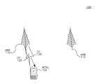
도 1은 WTRU가 CC 대역폭을 집성하여 데이터 전송 속도를 증가시키도록 협력하여 구성된 다수의 컴포넌트 캐리어(CC)와의 소정의 무선 통신 시스템의 예를 나타내는 도면.
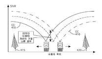
도 2는 상이한 사이트와 연관된 상이한 CC로부터 셀 커버리지 중첩 영역을 생성하면서 상이한 송신 전력으로 각 사이트 상에 2개의 DL CC가 구성될 수 있는 무선 통신 시스템의 예를 나타내는 도면.
도 3a는 하나 이상의 개시된 실시예가 구현될 수 있는 예시적인 통신 시스템을 나타내는 도면.
도 3b는 도 3a에 도시된 통신 시스템 내에서 사용될 수 있는 예시적인 무선 송수신 유닛(WTRU)을 나타내는 도면.
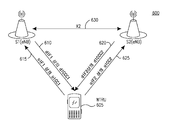
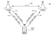
도 3c는 도 3a에 도시된 통신 시스템 내에서 사용될 수 있는 예시적인 무선 액세스 네트워크 및 예시적인 코어 네트워크를 나타내는 도면.
도 4는 무선 통신 시스템 셀 경계에서 WTRU 수신 신호대 간섭 및 잡음(SINR)을 개선하기 위한 CC의 사용을 나타내는 도면.
도 5는 하나의 CC 주파수 내의 섹터 안테나의 회전의 개념도.
도 6 내지 12는 2개의 상이한 사이트(eNB)와 통신하는 WTRU에 대한 다양한 동작 시나리오를 나타내는 도면.
도 13은 기지국의 기하학적 레이아웃을 나타내는 도면.
도 14는 전력 프로파일을 갖는 CC에 대한 최적화된 캐리어 대 간섭비(C/I)를 나타내는 도면.
도 15는 동일한 전력 및 동일하지 않은 전력을 갖는 비정규화된 합산 레이트의 CDF(cumulative distribution function)의 그래프.
도 16은 각각의 WTRU가 3개의 CC를 이용한다는 가정 하에서의 정규화된 합산 레이트의 CDF의 그래프.
도 17은 협력 컴포넌트 캐리어(cooperative component carrier) 내의 이동성에 의한 예시적인 무선 링크 실패를 나타내는 도면.
도 18은 예시적인 eNB 액세스 층(stratum) 프로토콜 아키텍쳐를 나타내는 도면.Will be better understood from the following description with reference to the accompanying drawings.
1 illustrates an example of a given wireless communication system with multiple component carriers (CC) configured in cooperation with a WTRU to aggregate the CC bandwidth and increase the data rate.
2 is an illustration of an example of a wireless communication system in which two DL CCs can be configured on each site with different transmit power while creating cell coverage overlap areas from different CCs associated with different sites.
3A illustrates an exemplary communication system in which one or more disclosed embodiments may be implemented;
3B is an illustration of an exemplary wireless transmit / receive unit (WTRU) that may be used within the communication system shown in FIG. 3A;
3C is an illustration of an exemplary radio access network and an exemplary core network that may be used within the communication system shown in FIG. 3A;
4 illustrates the use of CC to improve WTRU received signal-to-interference and noise (SINR) at a wireless communication system cell boundary;
5 is a conceptual diagram of rotation of a sector antenna within one CC frequency.
Figures 6-12 illustrate various operational scenarios for WTRUs communicating with two different sites (eNBs);
13 is a diagram showing a geometric layout of a base station;
14 shows an optimized carrier-to-interference ratio (C / I) for a CC with a power profile;
15 is a graph of a cumulative distribution function (CDF) of an irregularized summation rate with equal power and unequal power.
16 is a graph of the CDF of the normalized summation rate under the assumption that each WTRU utilizes three CCs.
17 illustrates exemplary radio link failure by mobility within a cooperative component carrier;
18 illustrates an exemplary eNB access layer (stratum) protocol architecture;
이하에서, 용어 "무선 송수신 유닛(WTRU)"는, 제한되지 않지만, 사용자 장치(WTRU), 이동국, 고정 또는 이동 가입자 유닛, 페이저, 셀룰러 전화, 개인 휴대 단말기(PDA), 컴퓨터, 또는 무선 환경에서 동작할 수 있는 임의의 다른 타입의 사용자 장치를 포함한다. 이하에서, 용어 "기지국"은, 제한되지 않지만, Node-B, eNB, 사이트 컨트롤러, 액세스 포인트(AP) 또는 무선 환경에서 동작할 수 있는 임의의 다른 타입의 인터페이싱 장치를 포함한다.The term "WTRU" is used herein to refer to any type of mobile station, including but not limited to, a WTRU, a mobile station, a fixed or mobile subscriber unit, a pager, a cellular telephone, a personal digital assistant Or any other type of user device capable of operating. In the following, the term "base station" includes, but is not limited to, a Node-B, an eNB, a site controller, an access point (AP) or any other type of interfacing device capable of operating in a wireless environment.
더 높은 데이터 레이트 및 스펙트럼 효율을 지원하는 무선 통신 시스템은 직교 주파수 분할 다중 액세스(OFDMA) 무선 인터페이스에 기초한 DL 송신 방식을 이용할 수 있다. 상향링크(UL) 방향에 대하여, 이산 푸리에 변환(DFT) 확산 OFDMA(DFT-S-OFDMA)에 기초한 단일 캐리어(SC) 송신이 사용될 수 있다. UL에서의 단일 캐리어 송신의 사용은 직교 주파수 분할 멀티플렉싱(OFDM) 등의 멀티캐리어 송신과 비교하여 더 낮은 피크-대-평균 전력비(PAPR)에 의해 동기부여될 수 있다.Wireless communication systems supporting higher data rates and spectral efficiency may utilize a DL transmission scheme based on an orthogonal frequency division multiple access (OFDMA) air interface. For uplink (UL) directions, a single carrier (SC) transmission based on Discrete Fourier Transform (DFT) spreading OFDMA (DFT-S-OFDMA) may be used. The use of single carrier transmissions at UL can be motivated by a lower peak-to-average power ratio (PAPR) compared to multicarrier transmissions such as orthogonal frequency division multiplexing (OFDM).
무선 통신 무선 액세스 시스템의 달성가능한 스루풋 및 커버리지를 더 개선하고 DL 및 UL 방향에서 1Gbps 및 500Mbps 피크 데이터 레이트의 국제 모바일 텔레커뮤니케이션(IMT)의 진보된 요구사항을 충족하기 위하여, 유연한 대역폭 배치 특징을 지원하면서 20MHz로부터 100MHz까지 최대 송신 대역폭을 증가시키기 위하여 몇 개의 캐리어가 집성될 수 있다. 각각의 캐리어(즉, 컴포넌트 캐리어(CC))는 20MHz의 최대 대역폭을 가질 수 있다. CA는 DL 및 UL에서 지원된다. 추가적으로, 상이한 CC는 상이한 커버리지를 가질 수 있다.Supports flexible bandwidth allocation features to further improve the achievable throughput and coverage of wireless communication radio access systems and meet the advanced requirements of International Mobile Telecommunications (IMT) with 1 Gbps and 500 Mbps peak data rates in DL and UL directions. Several carriers may be aggregated to increase the maximum transmission bandwidth from 20 MHz to 100 MHz. Each carrier (i.e., component carrier CC) may have a maximum bandwidth of 20 MHz. CA is supported on DL and UL. Additionally, different CCs may have different coverage.
다수의 CC를 이용하는 CA의 개념은 무선 자원 제어(RRC) 접속 상태의 무선 송수신 유닛(WTRU)에 관련된다. 유휴 WTRU는 단일 UL 및 DL 캐리어 쌍을 통해 네트워크를 액세스할 것이다. CA는 단일 eNB 상에서 지원될 수 있다. CA가 구현되면, 셀은 고유한 E-UTRAN(E-UMTS(evolved universal mobile telecommunications system) terrestrial radio access network) 셀 글로벌 아이덴티티(ECGI)에 의해 식별되고, 셀은 하나의 CC 내의 시스템 정보의 송신에 대응한다. 앵커 캐리어는 소정의 셀에 시스템 정보, 동기 및 페이징을 제공하는 캐리어이다. 또한, 앵커 캐리어는 WTRU의 관점으로부터 간섭 조정(interference coordination)이 적어도 하나의 검출가능한(액세스가능한) 앵커 캐리어를 제공하는 이종 네트워크 환경에서 동기, 캠핑(camping), 액세스 및 신뢰성있는 제어 커버리지를 가능하게 한다. 이 컨텍스트에서, WTRU 특정 앵커 캐리어가 셀 특정 앵커 캐리어의 서브세트로 간주될 수 있다. WTRU 특정 앵커 캐리어는 다수의 개별 물리적 DL 제어 채널(PDCCH)을 전달하는데 사용될 수 있고, 각각의 PDCCH는 하나의 CC에 대응한다.The concept of a CA using multiple CCs is associated with a wireless transmit / receive unit (WTRU) in a radio resource control (RRC) connected state. The idle WTRU will access the network through a single UL and DL carrier pair. The CA may be supported on a single eNB. When the CA is implemented, the cell is identified by a unique E-UTRAN (Evolved Universal Mobile Telecommunications System) terrestrial radio access network (ECGI) cell global identity (ECGI) Respectively. An anchor carrier is a carrier that provides system information, synchronization, and paging to a given cell. In addition, an anchor carrier may enable synchronization, camping, access, and reliable control coverage in a heterogeneous network environment in which the interference coordination from the perspective of the WTRU provides at least one detectable (accessible) anchor carrier do. In this context, a WTRU specific anchor carrier may be considered a subset of the cell specific anchor carriers. A WTRU specific anchor carrier may be used to carry a plurality of separate physical DL control channels (PDCCHs), each PDCCH corresponding to one CC.
소정의 무선 통신 시스템에서, 다음의 3개의 파라미터, 즉, 기준 신호 전력, ![]()
![]()
![]()
![]()
![]()
![]()
![]()
![]()
![]()
![]()
![]()
![]()
![]()
![]()
![]()
![]()
![]()
![]()
![]()
![]()
소정의 무선 통신 시스템에서, 기준 신호 전력, ![]()
![]()
![]()
![]()
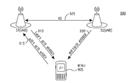
도 1은 WTRU(105) 및 2개의 사이트(eNB(110 및 115))를 포함하는 무선 통신 시스템(100)의 일 예를 나타낸다. 시스템(100)은 WTRU(105)가 CC 대역폭을 집성하여 데이터 전송 레이트를 증가시키도록 구성된다. 도 1에 도시된 바와 같이, WTRU(105)는 2개의 개별 CC, 즉, CC(120) 및 CC(125)를 통해 eNB(110)와만 통신한다. WTRU가 상이한 사이트로부터 CC 상에서 데이터를 수신하는 것을 금지하는 특정 제한(예를 들어, 그랜트 금지 메카니즘(no granting mechanism), 타이밍 어드밴스, 채널 품질 지시기(CQI) 시그널링, 포지티브 ACK/NACK 시그널링 등)이 있을 수 있다. 1 shows an example of a
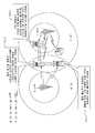
예를 들어, 도 2는 2개의 DL CC가 구성될 수 있는 하나의 가능한 무선 통신 시스템을 나타낸다. 각각의 사이트는 상이한 전력으로(즉, 풀 전력 또는 감소된 전력) CC 상에서 송신한다. 모든 WTRU는 소정의 CC 상에서 수락가능한 레벨의 신호 대 간섭 및 잡음비(SINR)를 경험한다. 도 2는 WTRU(105)가 CC2 및 CC3이 액세스될 수 있는 WTRU(1)의 위치에 있는 시나리오를 나타낸다. WTRU(105)가 WTRU(3)의 위치에 있으면, CC1 및 CC4가 액세스될 수 있다. WTRU(105)가 WTRU(2)의 위치에 있으면, CC1 또는 CC2 중 하나만이 액세스될 수 있다. 예를 들어, WTRU(105)가 사이트(1) 상에서 CC2를 액세스하면, 네트워크 무선 자원 관리(RRM) 엔티티(미도시)는 상이한 사이트로부터의 다수의 CC를 이용함으로써 데이터 스루풋 증가의 전체 이득을 취하기보다는 사이트(1) 상에서 CC1을 액세스하기 위하여 CC2를 드롭하도록 핸드오버가 수행되는지를 결정할 수 있다.For example, FIG. 2 shows one possible wireless communication system in which two DL CCs may be constructed. Each site transmits on a CC with different power (i.e., full power or reduced power). All WTRUs experience an acceptable level of signal-to-interference and noise ratio (SINR) on a given CC. Figure 2 shows a scenario in which the
예를 들어, 사이트마다 2개의 UL CC(UC) 주파수, 즉, UC 주파수(1) 및 UC 주파수(2)가 존재하면, 이들 UL CC 주파수의 각각에서의 WTRU(1) 및 사이트(1) 사이의 경로 손실은 사이트(2)에 대한 경로 손실보다 작을 수 있다. 마찬가지로, WTRU(3)에 대하여, 사이트(2)로의 경로 손실은 더 유리할 수 있다. 그러나, WTRU(2)에 대하여, UL 채널 품질은 DL 신호 품질과 다를 수 있다. 따라서, 사이트(2)에 의해 CC1 상에서의 증가된 송신 전력 때문에 CC1 상에서의 DL 송신이 사이트(2)로부터 수신되어도, UC 주파수(1) 및 UC 주파수(2)에 대한 경로 손실은 사이트(1)보다 작을 수 있다.For example, if there are two UL CC (UC) frequencies per site, i.e.,
도 3a는 하나 이상의 개시된 실시예가 구현될 수 있는 일 예의 통신 시스템(300)을 나타낸다. 통신 시스템(300)은 음성, 데이터, 비디오, 메시징, 방송 등의 콘텐츠를 다수의 무선 사용자에게 제공하는 다수의 액세스 시스템일 수 있다. 통신 시스템(300)은 다수의 무선 사용자가 무선 대역폭을 포함하는 시스템 자원의 공유를 통해 이러한 콘텐츠를 액세스할 수 있게 한다. 예를 들어, 통신 시스템(300)은 코드 분할 다중 액세스(CDMA), 시간 분할 다중 액세스(TDMA), 주파수 분할 다중 액세스(FDMA), 직교 FDMA(OFDMA), 단일 캐리어 FDMA(SC-FDMA) 등의 하나 이상의 채널 액세스 방법을 채용할 수 있다.Figure 3A illustrates an
도 3a에 도시된 바와 같이, 개시된 실시예는 임의의 수의 WTRU, 기지국, 네트워크 및/또는 네트워크 엘리먼트를 포함할 수 있지만, 통신 시스템(300)은 무선 송수신 유닛(WTRU)(302a, 302b, 302c, 302d), 무선 액세스 네트워크(RAN)(304), 코어 네트워크(306), PSTN(public switched telephone network)(308), 인터넷(310) 및 다른 네트워크(312)를 포함할 수 있다. WTRU(302a, 302b, 302c, 302d)의 각각은 무선 환경에서 동작 및/또는 통신하도록 구성되는 임의의 타입의 장치일 수 있다. 예로서, WTRU(302a, 302b, 302c, 302d)는 무선 신호를 송신 및/또는 수신하도록 구성되고 UE(user equipment), 이동국, 고정 또는 이동 가입자 유닛, 페이저, 셀룰러 전화, 개인 휴대 단말기(PDA), 스마트폰, 랩탑, 넷북, 개인 컴퓨터, 무선 센서, 소비자 전자장치 등을 포함할 수 있다.3A, the
통신 시스템(300)은 또한 기지국(314a) 및 기지국(314b)을 포함할 수 있다. 기지국(314a 및 314b)의 각각은 WTRU(302a, 302b, 302c, 302d) 중의 적어도 하나와 무선으로 인터페이스하여 코어 네트워크(306), 인터넷(310) 및/또는 네트워크(312) 등의 하나 이상의 통신 네트워크로의 액세스를 가능하게 하는 임의의 타입을 장치일 수 있다. 예로서, 기지국(314a, 314b)은 베이스 트랜시버 스테이션(BTS), Node-B, eNode B, 홈 노드 B, 홈 eNode B, 사이트 컨트롤러, 액세스 포인트(AP), 무선 라우터, RRH(remote radio head) 등일 수 있다. 기지국(314a, 314b)은 각각 단일 엘리먼트로 도시되지만, 기지국(314a, 314b)은 임의의 수의 상호접속된 기지국 및/또는 네트워크 엘리먼트를 포함할 수 있다.
기지국(314a)은 다른 기지국 및/또는 기지국 컨트롤러(BSC), 무선 네트워크 컨트롤러(RNC), 릴레이 노드 등의 네트워크 엘리먼트(미도시)를 또한 포함할 수 있는 RAN(304)의 일부일 수 있다. 기지국(314a) 및/또는 기지국(314b)은 셀(미도시)이라 불리울 수 있는 특정한 지리적 영역 내의 무선 신호를 송신 및/또는 수신하도록 구성될 수 있다. 셀은 셀 섹터로 더 분할될 수 있다. 예를 들어, 기지국(314a)과 관련된 셀이 3개의 섹터로 분할될 수 있다. 따라서, 일 실시예에서, 기지국(314a)은 3개의 트랜시버, 즉, 셀의 각 섹터에 대한 트랜시버를 포함할 수 있다. 다른 실시예에서, 기지국(314a)은 MIMO(multiple-input multiple output) 기술을 채용할 수 있고, 따라서, 셀의 각 섹터에 대한 다수의 트랜시버를 이용할 수 있다.Base station 314a may be part of
기지국(314a, 314b)은 임의의 적절한 무선 통신 링크(예를 들어, 무선 주파수(RF), 마이크로웨이브, 적외선(IR), 자외선(UV), 가시광 등)일 수 있는 무선 인터페이스(316)를 통해 WTRU(302a, 302b, 302c, 302d) 중의 하나 이상과 통신할 수 있다. 무선 인터페이스(316)는 임의의 적절한 무선 액세스 기술(RAT)을 이용하여 확립될 수 있다.The base stations 314a and 314b may be coupled via a
특히, 상술한 바와 같이, 통신 시스템(300)은 다중 액세스 시스템일 수 있고 CDMA, TDMA, FDMA, OFDMA, SC-FDMA 등의 하나 이상의 채널 액세스 방식을 채용할 수 있다. 예를 들어, RAN3104)내의 기지국(314a) 및 WTRU(302a, 302b, 302c)는 와이드밴드 CDMA(WCDMA)를 이용하여 무선 인터페이스(316)를 확립할 수 있는 UMTS(Universal Mobile Telecommunications System) UTRA(Terrestrial Radio Access) 등의 무선 기술을 구현할 수 있다. WCDMA는 HSPA(High-Speed Packet Access) 및/또는 HSPA+(Evolved HSPA) 등의 무선 프로토콜을 포함할 수 있다. HSPA는 HSDPA(High-Speed Downlink Packet Access) 및/또는 HSUPA(High-Speed Uplink Packet Access)를 포함할 수 있다.In particular, as described above,
또 다른 실시예에서, 기지국(314a) 및 WTRU(302a, 302b, 302c)는 LTE(Long Term Evolution) 및/또는 LTE-A(LTE-Advanced)를 이용하여 무선 인터페이스(316)를 확립할 수 있는 E-UTRA(Evolved UMTS Terrestrial Radio Access) 등의 무선 기술을 구현할 수 있다.In another embodiment, base station 314a and
다른 실시예에서, 기지국(314a) 및 WTRU(302a, 302b, 302c)는 IEEE 802.16(즉, WiMAX(Worldwide Interoperability for Microwave Access)), CDMA2000, CDMA2000 1X, CDMA2000 EV-DO, IS-2000(Interim Standard 2000), IS-95, IS-856, GSM(Global system for Mobile communications, EDGE(Enhanced Data rates for GSM Evolution), GERAN(GSM/EDGE RAN) 등의 무선 기술을 구현할 수 있다.In other embodiments, the base station 314a and the
도 3a의 기지국(314b)은 예를 들어 무선 라우터, 홈 노드 B, HNB, RNC 및 노드B의 조합, eNB, HeNB, 관련된 기지국을 갖는 RRH, 또는 AP일 수 있고 회사, 집, 차량, 캠퍼스 등의 국한된 영역 내의 무선 접속을 가능하게 하는 임의의 적절한 RAT를 이용할 수 있다. 일 실시예에서, 기지국(314b) 및 WTRU(102c, 102d)는 IEEE 802.11 등의 무선 기술을 구현하여 무선 근거리 통신망(WLAN)을 확립할 수 있다. 또 다른 실시예에서, 기지국(314b) 및 WTRU(302c, 302d)는 IEEE 802.15 등의 무선 기술을 구현하여 무선 개인 통신망(WPAN)을 확립할 수 있다. 또 다른 실시예에서, 기지국(314b) 및 WTRU(302c, 302d)는 셀룰러 기반 RAT(예를 들어, WCDMA, CDMA2000, GSM, LTE, LTE-A 등)를 이용하여 피코셀 또는 펨토셀을 확립할 수 있다. 도 3a에 도시된 바와 같이, 기지국(314b)은 인터넷(310)으로의 직접 접속부를 가질 수 있다. 따라서, 기지국(314b)은 코어 네트워크(306)를 통해 인터넷(310)을 액세스하도록 요구되지 않을 수 있다.The base station 314b of Figure 3A may be, for example, a combination of a wireless router, a home Node B, a HNB, an RNC and a Node B, an eNB, an HeNB, an RRH with an associated base station, Lt; RTI ID = 0.0 > RAT < / RTI > In one embodiment, base station 314b and WTRUs 102c and 102d may implement a wireless technology such as IEEE 802.11 to establish a wireless local area network (WLAN). In another embodiment, base station 314b and
RAN(304)은 음성, 데이터, 애플리케이션 및/또는 VoIP(voice over internet protocol) 서비스를 WTRU(302a, 302b, 302c, 302d) 중의 하나 이상에 제공하도록 구성되는 임의의 타입의 네트워크일 수 있는 코어 네트워크(306)와 통신할 수 있다. 예를 들어, 코어 네트워크(106)는 호 제어, 빌링(billing) 서비스, 이동 위치 기반 서비스, 선불 호(prepaid calling), 인터넷 접속, 비디오 분배 등을 제공할 수 있고 및/또는 사용자 인증 등의 하이 레벨 보안 기능을 수행할 수 있다. 도 3a에는 도시되지 않지만, RAN(304) 및/또는 코어 네트워크(306)는 RAN(104)와 동일한 RAT 또는 상이한 RAT를 채용하는 다른 RAN과 직접 또는 간접 통신할 수 있다. 예를 들어, E-UTRA 무선 기술을 이용할 수 있는 RAN(104)에 접속되는 것에 더하여, 코어 네트워크(306)는 또한 GSM 무선 기술을 채용하는 또 다른 RAN(미도시)와 통신할 수 있다.
코어 네트워크(306)는 또한 PSTN(308), 인터넷(310) 및/또는 다른 네트워크(312)를 액세스하는 WTRU(302a, 302b, 302c, 302d)에 대한 게이트웨이로서 기능할 수 있다. PSTN(308)은 POTS(plain old telephone service)를 제공하는 회로 스위치 전화망을 포함할 수 있다. 인터넷(310)은 TCP/IP 인터넷 프로토콜 세트 내의 TCP(transmission control protocol), UDP(user datagram protocol) 및 인터넷 프로토콜(IP) 등의 공통 통신 프로토콜을 이용하는 상호 접속된 컴퓨터 네트워크 및 장치의 글로벌 시스템을 포함할 수 있다. 네트워크(312)는 다른 서비스 제공자에 의해 소유 및/또는 동작되는 유선 또는 무선 통신 네트워크를 포함할 수 있다. 예를 들어, 네트워크(312)는 RAN(304)와 동일한 RAT 또는 상이한 RAT를 채용할 수 있는 하나 이상의 RAN에 접속된 또 다른 코어 네트워크를 포함할 수 있다.The
통신 시스템 내의 WTRU(302a, 302b, 302c, 302d)의 일부 또는 전부는 멀티모드 능력을 포함할 수 있고, 즉, WTRU(302a, 302b, 302c, 302d)는 상이한 무선 링크를 통해 상이한 무선 네트워크와 통신하는 다수의 트랜시버를 포함할 수 있다. 예를 들어, 도 3a에 도시된 WTRU(302c)는 셀룰러 기반 무선 기술을 채용할 수 있는 기지국(314a) 및 IEEE 802 무선 기술을 채용할 수 있는 기지국(314b)과 통신하도록 구성될 수 있다.Some or all of the
도 3b는 도 3a에 도시된 통신 시스템(300) 내에서 사용될 수 있는 예시적인 WTRU(302)를 나타낸다. 도 3b에 도시된 바와 같이, WTRU(302)는 프로세서(318), 트랜시버(320), 송수신 엘리먼트(322)(예를 들어, 안테나), 스피커/마이크로폰(324), 키패드(326), 디스플레이/터치패드(328), 비착탈식 메모리(330), 착탈식 메모리(332), 전원(334), GPS(global positioning system) 칩셋(336) 및 다른 주변 장치(338)를 포함할 수 있다. WTRU(302)는 실시예와 일관성을 유지하면서 상기 엘리먼트의 임의의 서브 조합을 포함할 수 있다.FIG. 3B shows an
프로세서(318)는 범용 프로세서, 특수 목적 프로세서, 종래의 프로세서, 디지털 신호 프로세서(DSP), 복수의 마이크로프로세서, DSP 코어와 연관된 하나 이상의 마이크로프로세서, 컨트롤러, 마이크로컨트롤러, ASIC(Application Specific Integrated Circuits), FPGA(Field Programmable Gate Array) 회로, 임의의 다른 타입의 집적 회로(IC), 상태 머신 등일 수 있다. 프로세서(318)는 신호 코딩, 데이터 프로세싱, 전력 제어, 입출력 프로세싱 및/또는 WTRU(302)가 무선 환경에서 동작하도록 하는 임의의 다른 기능을 수행할 수 있다. 프로세서(318)는 송수신 엘리먼트(322)에 결합될 수 있는 트랜시버(320)에 결합될 수 있다. 도 3b는 프로세서(318) 및 트랜시버(320)를 별도의 구성요소로서 도시하지만, 프로세서(318) 및 트랜시버(320)는 전자 패키지 또는 칩 내에 함께 통합될 수 있음을 인식할 것이다.The
송수신 엘리먼트(322)는 무선 인터페이스(316)를 통해 기지국(예를 들어, 기지국(314a))으로/로부터 신호를 송신/수신하도록 구성될 수 있다. 예를 들어, 일 실시예에서, 송수신 엘리먼트(322)는 RF 신호를 송신 및/또는 수신하도록 구성된 안테나일 수 있다. 또 다른 실시예에서, 송수신 엘리먼트(322)는 예를 들어 IR, UV 또는 가시광 신호를 송신 및/또는 수신하도록 구성된 에미터/디텍터일 수 있다. 또 다른 실시예에서, 송수신 엘리먼트(322)는 RF 및 광 신호를 송수신하도록 구성될 수 있다. 송수신 엘리먼트(322)는 무선 신호의 임의의 조합을 송신 및/또는 수신하도록 구성될 수 있다.The transmit / receive
또한, 송수신 엘리먼트(322)가 단일 엘리먼트로서 도 3b에 도시되지만, WTRU(302)는 임의의 수의 송수신 엘리먼트(322)를 포함할 수 있다. 특히, WTRU(302)는 MIMO 기술을 채용할 수 있다. 따라서, 일 실시예에서, WTRU(302)는 무선 인터페이스(316)를 통해 무선 신호를 송수신하는 2 이상의 송수신 엘리먼트(322)(예를 들어, 다수의 안테나)를 포함할 수 있다.In addition, although the transmit / receive
트랜시버(320)는 송수신 안테나(322)에 의해 송신되는 신호를 변조하고 송수신 엘리먼트(322)에 의해 수신된 신호를 복조하도록 구성될 수 있다. 상술한 바와 같이, WTRU(302)는 멀티모드 능력을 가질 수 있다. 따라서, 트랜시버(320)는 예를 들어 WTRU(302)가 UTRA 및 IEEE 802.11 등의 다수 RAT를 통해 통신하도록 하는 다수의 트랜시버를 포함할 수 있다.The
WTRU(302)의 프로세서(318)는 스피커/마이크로폰(324), 키패드(326) 및/또는 디스플레이/터치패드(328)(예를 들어, 액정 표시(LCD) 디스플레이 유닛 또는 유기 발광 다이오드(OLED) 디스플레이 유닛)에 결합되어 그로부터 사용자 입력 데이터를 수신할 수 있다. 프로세서(318)는 또한 스피커/마이크로폰(324), 키패드(326), 및/또는 디스플레이/터치패드(328)로 사용자 데이터를 출력할 수 있다. 또한, 프로세서(318)는 비착탈식 메모리(330) 및/또는 착탈식 메모리(332) 등의 임의의 타입의 적절한 메모리로부터 정보를 액세스하거나 그 메모리에 데이터를 저장할 수 있다. 비착탈식 메모리(330)는 랜덤 액세스 메모리(RAM), 판독 적용 메모리(ROM), 하드 디스크 또는 임의의 다른 타입의 메모리 저장 장치를 포함할 수 있다. 착탈식 메모리(332)는 가입자 식별 모듈(SIM) 카드, 메모리 스틱, SD(secure digital) 메모리 카드 등을 포함할 수 있다. 다른 실시예에서, 프로세서(318)는 서버 또는 홈 컴퓨터(미도시) 등의 WTRU(302) 상에 물리적으로 위치하지 않는 메모리로부터 정보를 액세스하고 그 내에 데이터를 저장할 수 있다.The
도 3c는 도 3a에 도시된 통신 시스템(300) 내에서 사용될 수 있는 예시적인 RAN(304) 및 예시적인 코어 네트워크(306)를 나타낸다. 상술한 바와 같이, RAN(304)은 E-UTRA, WCDMA 또는 GSM 무선 기술을 채용하여 무선 인터페이스(316)를 통해 WTRU(302a, 302b, 302c)와 통신할 수 있다. RAN(304)은 또한 코어 네트워크(306)와 통신할 수 있다.FIG. 3C shows an
RAN(304)은 실시예와의 일관성을 유지하면서 임의의 수의 eNode-B를 포함할 수 있지만, RAN(304)은 eNode-B(340a, 340b, 340c)를 포함할 수 있다. eNode-B(340a, 340b, 340c)는 각각 무선 인터페이스(316)를 통해 WTRU(302a, 302b, 302c)와 통신하는 하나 이상의 트랜시버를 포함할 수 있다. 일 실시예에서, eNode-B(340a, 340b, 340c)는 MIMO 기술을 구현할 수 있다. 따라서, eNode-B(340a)는 예를 들어 다수의 안테나를 이용하여 WTRU(302a)로/로부터 무선 신호를 송신/수신할 수 있다.
eNode-B(340a, 340b, 340c)의 각각은 특정 셀(미도시)과 연관될 수 있고, 무선 자원 관리 결정, 핸드오버 결정, 상향링크 및/또는 하향링크에서의 사용자의 스케줄링 등을 처리하도록 구성될 수 있다. 도 3c에 도시된 바와 같이, eNode-B(340a, 340b, 340c)는 X2 인터페이스를 통해 서로 통신할 수 있다.Each of the eNode-
도 3c에 도시된 코어 네트워크(306)는 MME(mobility management gateway)(342), 서빙 게이트웨이(S-GW)(344) 및 PDN(packet data network) 게이트웨이(346)를 포함할 수 있다. 상기 엘리먼트의 각각이 코어 네트워크(306)의 일부로서 도시되지만, 이들 엘리먼트의 임의의 하나는 코어 네트워크 오퍼레이터 이외의 엔티티에 의해 소유 및/또는 동작될 수 있다는 인식할 것이다.The
MME(342)는 S1 인터페이스를 통해 RAN(304) 내의 eNode-B(342a, 342b, 342c)의 각각에 접속될 수 있고 제어 노드로서 동작할 수 있다. 예를 들어, MME(342)는 WTRU(302a, 302b, 302c)의 사용자의 컨텍스트의 인증, 관리 및 저장, 베어러 활성화/비활성화, WTRU(302a, 302b, 302c)의 초기 부착시 특정 서빙 게이트웨이의 선택 등을 수행할 수 있다. MME(342)는 또한 RAN(304) 및 GSM 또는 WCDMA 등의 다른 무선 기술을 채용하는 다른 RAN(미도시) 간의 스위칭을 위한 제어 평면 기능을 제공할 수 있다. S-GW(344)는 게이트웨이 GPRS(general packet radio service) 지원 노드일 수 있다. S-GW(344)는 S1 인터페이스를 통해 RAN(304) 내의 eNode-B(340a, 340b, 340c)의 각각에 접속될 수 있다. S-GW(344)는 일반적으로 WTRU(302a, 302b, 302c)로/로부터 사용자 데이터 패킷을 라우팅 및 전달할 수 있다. S-GW(344)는 또한 eNB간 핸드오버시의 사용자 평면 앵커(anchoring), DL 데이터가 WTRU(302a, 302b, 302c)에 이용가능할 때의 페이징 트리거링 등의 다른 기능을 수행할 수 있다. S-GW(344)는 서빙 GPRS 지원 노드(SGSN)일 수 있다.The
S-GW(344)는 인터넷(310) 등의 패킷 스위치 네트워크로의 액세스를 WTRU(302a, 302b, 302c)에 제공하는 PDN 게이트웨이(346)에 접속되어 WTRU(302a, 302b, 302c) 및 IP 가능 장치 간의 통신을 가능하게 할 수 있다.The S-
코어 네트워크(306)는 다른 네트워크와의 통신을 가능하게 할 수 있다. 예를 들어, 코어 네트워크(306)는 PSTN(408) 등의 회로 스위치 네트워크로의 액세스를 WTRU(302a, 302b, 302c)에 제공하여 WTRU(302a, 302b, 302c)와 전통적인 지상 통신 장치 간의 통신을 가능하게 할 수 있다. 예를 들어, 코어 네트워크(306)는 코어 네트워크(306) 및 PSTN(308) 간의 인터페이스로서 기능하는 IP 게이트웨이(예를 들어, IP 멀티미디어 서브시스템(IMS) 서버)를 포함하거나 그와 통신할 수 있다. 또한, 코어 네트워크(306)는 다른 서비스 제공자에 의해 소유 및/또는 동작되는 다른 유선 또는 무선 네트워크를 포함할 수 있는 다른 네트워크(312)로의 액세스를 WTRU(302a, 302b, 302c)에 제공할 수 있다.The
유연한 배치를 위하여, 소정의 무선 통신 시스템은 1.4, 3, 5, 10, 15 또는 20 MHz의 확장가능한 송신 대역폭을 지원한다. 이들 시스템은 주파수 분할 듀플렉스(FDD), 시간 분할 TDD 또는 하프-듀플렉스 FDD 모드에서 동작할 수 있다.For flexible deployment, certain wireless communication systems support scalable transmission bandwidths of 1.4, 3, 5, 10, 15 or 20 MHz. These systems may operate in Frequency Division Duplex (FDD), Time Division TDD, or Half-Duplex FDD modes.
소정의 무선 통신 시스템에서, 각각의 무선 프레임(10ms)은 각각 1ms의 동일 사이즈를 갖는 10개의 서브프레임으로 구성될 수 있다. 각각의 서브프레임은 0.5ms의 동일한 사이즈를 갖는 타임 슬롯으로 구성될 수 있다. 타임 슬롯당 7개 또는 6개의 OFDM 심볼이 존재할 수 있다. 일반 CP(cyclic prefix) 길이에 대해서는 7개의 심볼이 사용될 수 있고, 다른 시스템 구성에서 확장 CP 길이에 대해서는 타임 슬롯당 6개의 심볼이 사용될 수 있다. 이들 시스템에 대한 서브캐리어 간격은 15kHz일 수 있다. 7.5kHz를 이용하는 다른 감소된 서브캐리어 간격 모드가 또한 가능하다. 자원 요소(RE)는 1 OFDM 심볼 간격 동안 1 서브캐리어에 대응할 수 있다. 0.5ms 타임 슬롯 동안의 12개의 연속 서브캐리어는 하나의 자원 블록(RB)을 구성한다. 그러므로, 타임 슬롯당 7개의 심볼로, 각각의 RB는 12×7=84개의 RE로 구성될 수 있다. DL 캐리어는 최소 6RB로부터 최대 100RB까지의 확장가능한 수의 자원 블록(RB)으로 구성될 수 있다. 이것은 대략 1MHz로부터 20MHz까지의 전체 확장가능한 송신 대역폭에 대응한다. 공통 송신 대역폭의 세트(예를 들어, 1.4, 3, 5, 10 또는 20MHz)가 특정될 수 있다. 동적 스케줄링을 위한 기본 시간 도메인 유닛은 2개의 연속 타임 슬롯(즉, 자원 블록 쌍)을 포함하는 하나의 서브프레임일 수 있다. 임의의 OFDM 심볼 상의 소정의 서브캐리어는 시간-주파수 그리드 내의 파일럿 신호를 나르기 위하여 할당될 수 있다. 송신 대역폭의 에지에서의 주어진 수의 서브캐리어가 스펙트럼 마스크 요구사항에 순응하기 위하여 송신되지 않을 수 있다.In a given wireless communication system, each radio frame (10 ms) may be composed of 10 subframes each having the same size of 1 ms. Each subframe may be composed of timeslots having the same size of 0.5 ms. There may be seven or six OFDM symbols per time slot. Seven symbols may be used for a general CP (cyclic prefix) length, and six symbols per time slot for an extended CP length in other system configurations. The subcarrier spacing for these systems may be 15 kHz. Other reduced subcarrier spacing modes using 7.5 kHz are also possible. The resource element RE may correspond to one subcarrier for one OFDM symbol interval. Twelve consecutive subcarriers during a 0.5 ms time slot constitute one resource block (RB). Therefore, with 7 symbols per time slot, each RB can be composed of 12 x 7 = 84 REs. The DL carrier may be comprised of an expandable number of resource blocks (RBs) from a minimum of 6RB to a maximum of 100RB. This corresponds to a total scalable transmission bandwidth from approximately 1 MHz to 20 MHz. A set of common transmit bandwidths (e.g., 1.4, 3, 5, 10, or 20 MHz) may be specified. The basic time domain unit for dynamic scheduling may be one subframe containing two consecutive time slots (i.e., resource block pairs). Certain subcarriers on any OFDM symbol may be assigned to carry the pilot signal in the time-frequency grid. A given number of subcarriers at the edge of the transmit bandwidth may not be transmitted in order to comply with the spectral mask requirements.
DL 방향에서, WTRU는 전체 송신 대역폭에 걸쳐, 예를 들어 OFDMA 방식이 사용될 수 있는 임의의 곳에서 자신의 데이터를 수신하도록 eNB에 의해 할당될 수 있다. DL은 스펙트럼의 중심에 사용하지 않은 DC(direct current) 오프셋 서브캐리어를 가질 수 있다.In the DL direction, the WTRU may be allocated by the eNB to receive its data over the entire transmission bandwidth, e.g., anywhere that the OFDMA scheme may be used. The DL may have an unused DC (direct current) offset subcarrier at the center of the spectrum.
DL 그랜트는 PDCCH 상에서 전달될 수 있다. 대역폭 집성을 지원하기 위하여, 개별 PDCCH 코딩(예를 들어, 상이한 CC에 대한 PDCCH 메시지가 개별 CRC(cyclic redundancy check) 및 콘볼루션 코드를 이용하여 인코딩되는 개별 코딩 수단)이 다음의 2개의 옵션으로 DL 자원을 스케줄링하는데 사용될 수 있다.The DL grant may be delivered on the PDCCH. To support bandwidth aggregation, separate PDCCH coding (e.g., separate coding means in which PDCCH messages for different CCs are encoded using separate cyclic redundancy check (CRC) and convolutional codes) Can be used to schedule resources.
1) 옵션 1a: 각각의 캐리어 상의 개별 PDCCH는 그 캐리어의 DL 자원을 스케줄링하는데 사용될 수 있다.1) Option 1a: A separate PDCCH on each carrier may be used to schedule the DL resources of that carrier.
2) 옵션 1b: 주어진 캐리어 상에서의 개별 코딩의 하나의 PDCCH는 캐리어 지시기(CI) 필드에 의해 다수의 캐리어 상에서 자원을 스케줄링하는데 사용될 수 있다.2) Option 1b: One PDCCH of separate coding on a given carrier may be used to schedule resources on multiple carriers by a Carrier Indicator (CI) field.
WTRU는 모든 넌-DRX(non-discontinuous reception) 서브프레임 내의 제어 정보에 대한 PDCCH 후보 세트를 모니터링하는데 사용될 수 있고, 여기서, 모니터링은 다양한 모니터링 DL 제어 정보(DCI) 포맷에 따라 세트 내의 PDCCH의 각각을 디코딩하려고 시도하는 것을 암시한다.The WTRU may be used to monitor a PDCCH candidate set for control information in all non-discontinuous reception subframes, where the monitoring may be performed by monitoring each of the PDCCHs in the set according to various monitoring DL control information (DCI) Lt; / RTI >
소정의 무선 통신 시스템에서, WTRU가 모니터링하는 DCI 포맷은 WTRU 특정 검색 공간 및 공통 검색 공간으로 나누어질 수 있다. WTRU 특정 검색 공간에 대하여, WTRU는 송신 모드에 따라 RRC 시그널링을 통해 반정적으로 구성될 수 있는 DCI 및 DCI 0/1A를 모니터링할 수 있다. WTRU가 크로스 캐리어 스케줄링을 위해 스케줄링 할당을 수신하도록 구성될 수 있는 WTRU DL CC 세트로부터의 DL CC를 포함하는 PDCCH DL 모니터링 세트가 정의될 수 있다. WTRU는 PDCCH를 수신하도록 구성되지 않은 DL CC에서 블라인드 디코딩을 수행하지 않아 PDCCH 잘못 검출 확률을 감소시킬 수 있다.In some wireless communication systems, the DCI format monitored by the WTRU may be divided into a WTRU specific search space and a common search space. For a WTRU specific search space, the WTRU may monitor the DCI and
WTRU는 네트워크와의 하나의 RRC 접속부를 가질 수 있다. CC의 추가 및 제거는 RRC 접속 HO없이 수행될 수 있고, 제거의 경우, 제거될 CC는 특수 셀이 아니다. 특수 셀은 PCC(primary component carrier) 또는 WTRU에 대하여 제어 평면 시그널링 교환을 제공하는 캐리어일 수 있다.The WTRU may have one RRC connection with the network. Addition and removal of CC may be performed without an RRC connection HO, and in case of removal, CC to be removed is not a special cell. The special cell may be a primary component carrier (PCC) or a carrier that provides a control plane signaling exchange for the WTRU.
개별 활성화/비활성화는 MAC(medium access control) 또는 물리적(PHY) 기술을 이용하여 허용될 수 있다. CC는 2개의 상태, 즉, 1) 구성되지만 비활성화 상태 및 2) 활성화 상태에 존재할 수 있다. DL에서, WTRU는 비활성화된 CC 상에서 PDCCH 또는 PDSCH를 수신하지 않을 수 있다. 활성화된 캐리어 상에서, WTRU는 존재한다면 PDSCH 및 PDCCH를 수신할 수 있다. 또한, WTRU는 비활성화된 CC 상에서 CQI 측정을 수행하는데 사용되지 않을 수 있다. UL에서, 명시적인 활성화/비활성화 절차가 도입되지 않을 수 있다.Individual activation / deactivation may be allowed using medium access control (MAC) or physical (PHY) techniques. The CC can be in two states: 1) configured but inactive and 2) active. In the DL, the WTRU may not receive the PDCCH or PDSCH on the deactivated CC. On the activated carrier, the WTRU may receive PDSCH and PDCCH if present. In addition, the WTRU may not be used to perform CQI measurements on deactivated CCs. In UL, explicit activation / deactivation procedures may not be introduced.
네트워크는 이동성 측정을 구성하여 기준 신호 수신 전력(reference signal received power; RSRP) 또는 기준 신호 수신 품질(RSRQ)에 기초하여 WTRU 사이트간 핸드오버를 지원할 수 있다. 이웃 셀 측정을 보고하는 다수의 방법이 존재한다. 예를 들어, WTRU는 이벤트 또는 주기적 보고에 기초하여 이웃 셀 전력을 측정하도록 구성될 수 있다. 네트워크는 WTRU로부터의 이웃 셀 측정에 의존하여 주어진 CC 세트 내의 상이한 사이트로 WTRU가 핸드오버할 때를 결정한다. 이들 네트워크는 지원되는 CC에서 이웃 셀/사이트를 모니터링(예를 들어, 측정)하여 WTRU가 WTRU 이동성을 지지하여 전달되는 서비스 품질을 유지하는 CC로 이동하도록 WTRU를 구성한다. 주기적 측정 또는 측정 이벤트(1×, 및 2×)는 네트워크에 충분한 정보를 제공하여 사용될 수 있는 각각의 CC에 대하여 및 이러한 CC 특정(사이트간) 핸드오버(CSHO)가 발생할 때 특정 WTRU로 데이터를 송신하는데 사용될 수 있는 적절한 CC를 선택할 수 있다.The network may configure mobility measurements to support WTRU inter-site handover based on reference signal received power (RSRP) or reference signal reception quality (RSRQ). There are a number of ways to report neighbor cell measurements. For example, the WTRU may be configured to measure neighbor cell power based on an event or periodic report. The network relies on neighbor cell measurements from the WTRU to determine when the WTRU handles to a different site within a given CC set. These networks monitor (e.g., measure) neighbor cells / sites in the supported CC to configure the WTRU to move to the CC that maintains the quality of service delivered by supporting the WTRU mobility. Periodic measurement or measurement events (1x, and 2x) provide sufficient information to the network for each CC that can be used and data to a specific WTRU when such CC specific (inter-site) handover (CSHO) occurs. You can choose the appropriate CC that can be used to transmit.
소정의 무선 통신 시스템에서, 측정 이벤트(1×, 및 2×)는 CA로 구성된 WTRU에 대하여 적용될 수 있다. 이들 측정 이벤트는 핸드오버에 포함될 개별 CC를 식별할 수 있다.In some wireless communication systems, measurement events (1 x, and 2 x) may be applied for WTRUs configured with CAs. These measurement events can identify individual CCs to be included in the handover.
다수의 사이트로부터 데이터를 WTRU로 보낼 때, WTRU 데이터는 다수의 사이트에 존재할 수 있다. 일반적으로, 이것은 다수의 송신 포인트/사이트가 자신의 송신을 협력하는 협력 멀티포인트(CoMP) 송신과 동일한 방식으로 수행되면 백홀 상에 추가의 스트레인(strain)을 생성한다. 이 협력은 스케줄링에서의 협력, WTRU로의 데이터의 조인트 송신 등의 몇 개의 상이한 형태를 취할 수 있다. 조인트 송신에서, WTRU 데이터의 완전한 카피가 CoMP 송신에 참여한 각 사이트에서 이용가능하다. 하나의 EPS(evolved packet system) 무선 액세스 베어러(RAB)를 지원하는 다수의 CC의 아키텍쳐는 MAC(medium access control) 멀티플렉싱 및 디멀티플렉싱을 통해 무선 액세스 네트워크에 의해 유지된다. 이 어프로치에서, 데이터는 서빙 eNB에서 수신되어 모든 협력 CC/eNB에 카피 및 전달될 수 있다. 이것은 2개의 사이트를 포함하는 CoMP 조인트 송신에 참여한 WTRU마다 백홀 로드(backhaul load)를 대략 2배가 되게 한다. When sending data from multiple sites to a WTRU, the WTRU data may be in multiple sites. Generally, this creates additional strain on the backhaul when multiple transmission points / sites are performed in the same manner as Cooperative Multipoint (CoMP) transmissions cooperating with their transmissions. This cooperation may take several different forms, such as cooperation in scheduling, joint transmission of data to the WTRU, and so on. In the joint transmission, a complete copy of the WTRU data is available at each site participating in the CoMP transmission. The architecture of multiple CCs supporting an evolved packet system (RAB) radio access bearer (RAB) is maintained by the radio access network through medium access control (MAC) multiplexing and demultiplexing. In this approach, data may be received at the serving eNB and copied and delivered to all cooperating CC / eNBs. This approximately doubles the backhaul load for each WTRU participating in a CoMP joint transmission involving two sites.
주파수 재사용 1 배치에서 이웃 셀로부터의 간섭 제한에 의한 셀 에지 저하의 문제는 1) 시스템에서 각각의 CC에 셀 에지 내의 위치를 조작하고 및/또는 WTRU가 다수의 사이트로부터 데이터를 수신하도록 (예를 들어, 데이터는 캐리어(1) 상에서 사이트(A)로부터 수신되고 캐리어(2) 상에서 사이트(B)로부터 수신될 수 있다) 함으로써 완화된다. 이 방식으로, WTRU는 CC의 전체 집성 내의 각 CC에 대하여 최상의 스루풋(또는 다른 측정치)을 제공하는 사이트에 할당될 수 있어, 전통적인 셀룰러 설정에서처럼 셀 에지의 개념이 적용되지 않는 "퍼지 셀(fussy cell)" 개념을 생성한다. WTRU가 모든 CC 상에서 데이터를 수신할 수 있게 됨에 따라, 하나의 주파수 재사용이 유지될 수 있다. WTRU는 각각의 이용 가능 CC 상에서 데이터를 수신할 수 있다. WTRU에 대한 데이터의 송신 사이트의 위치는 시스템에서 동일 위치에 있지 않을 수 있다.The problem of cell edge degradation due to interference restriction from neighboring cells in a
셀 경계는 주어진 위치 및 임의의 CC에서 수신된 임의의 사이트로부터의 가장 큰 신호 전력 대 다른 신호(간섭) 및 잡음에서의 전력의 합산의 비에 의해 부분적으로 결정될 수 있다. 수신된 신호 및 간섭 전력은 경로 손실, 안테나 이득 및 각 셀로부터 WTRU 위치로의 송신 전력에 의해 부분적으로 결정될 수 있다. 셀 에지 위치의 조작은 몇 개의 상이한 기술을 이용하여 수행될 수 있다.Cell boundaries can be determined in part by the ratio of the largest signal power from any site received at a given location and any CC to the sum of the power at other signals (interference) and noise. The received signal and interference power may be determined in part by path loss, antenna gain, and transmit power from each cell to the WTRU location. The manipulation of the cell edge position may be performed using several different techniques.
일 실시예에서, WTRU는 각각의 DL을 통해 복수의 사이트와의 접속을 확립할 수 있다. 사이트는 Node-B, eNB, 기지국과 연관된 RRH 또는 Node-B 또는 eNB의 몇 개의 섹터 송신 안테나 중의 하나 중의 적어도 하나를 포함할 수 있다. 각각의 DL은 다른 DL CC 중의 하나 이상과 동일하거나 다른 주파수 상에서 동작하는 적어도 하나의 DL CC를 포함할 수 있다. 사이트는 특정한 DL CC 동작 주파수에 대하여 자신의 송신 전력을 조절하여 사이트 중의 특정한 하나로부터 자신의 셀 경계로의 거리가 특정한 동작 주파수 상에서 자신의 송신 전력을 증가시킴으로써 커지도록 하고, 다른 사이트 중의 적어도 하나로부터 각각의 셀 경계로의 거리가 특정한 동작 주파수 상에서 자신의 송신 전력을 감소시킴으로써 더 작아지도록 할 수 있다. 따라서, 1의 주파수 재사용 패턴을 유지하면서, 상이한 CC 주파수 사이의 커버리지 중첩이 생성될 수 있다.In one embodiment, the WTRU may establish a connection with a plurality of sites via each DL. The site may include a Node-B, an eNB, an RRH associated with the base station, or at least one of several sector transmit antennas of a Node-B or an eNB. Each DL may include at least one DL CC operating on the same or different frequency as one or more of the other DL CCs. The site may adjust its transmit power for a particular DL CC operating frequency such that the distance from a particular one of the sites to its cell boundary is increased by increasing its transmit power on a particular operating frequency, The distance to each cell boundary can be made smaller by decreasing its transmit power on a particular operating frequency. Thus, while maintaining a frequency reuse pattern of 1, coverage overlaps between different CC frequencies can be generated.
이 점을 설명하기 위하여, 도 4는 각 사이트에서 2개의 DL CC(405 및 410)의 각각의 SINR을 나타낸다. 각각의 사이트(415 및 420)에서, 하나의 CC는 다른 것보다 높은 전력으로 송신된다. 이들 CC(405 및 410)의 각각은 상이한 캐리어 주파수 및 잠재적으로 상이한 커버리지 영역을 갖는 자신의 셀로 간주될 수 있다. 상이한 커버리지 영역은 전파 조건의 차로부터 기인할 수 있다. 그러나, 소정의 시스템 파라미터는 또한 변경되어 송신 전력, HO 임계치, 섹터 안테나 방향 등의 DL 커버리지를 의도적으로 변경할 수 있다. 이것은 CC를 이용하여 DL 셀 에지 문제를 완하시키는 기회를 생성한다. 예를 들어, 커버리지 영역은 상이한 DL CC에 대하여 의도적으로 조절되어 WTRU가 부가된 모든 DL CC의 셀 에지에서 자신을 찾을 수 있는 시스템 내의 포인트가 없을 수 있다. 따라서, WTRU는 양 캐리어 주파수에서 셀 에지에 있지 않을 수 있다(예를 들어, WTRU가 하나의 캐리어에서 셀 에지에 있으면, 다른 캐리어에서 만족스러운 성능을 여전히 가질 수 있고, WTRU가 2개의 eNB 사이의 중심점 부근에 위치하면, 캐리어 SINR은 여전히 단일 캐리어 시스템의 SINR보다 좋을 수 있다).To illustrate this point, FIG. 4 shows the SINR of each of the two
추가적으로, 섹터 안테나 패턴(예를 들어, 빔폭, 브로드사이드(broadside) 각도, 또는 다른 빔 패턴 쉐이핑)이 조절되어 상이한 각도에서의 송신 전력 밀도를 제어할 수 있다. 따라서, 셀 에지 위치는, 셀 에지의 위치에 영향을 주는 각 구성요소(angular component)가 있다는 것을 제외하고(즉, 총 전력을 변경하는 것은 모든 발사각에서의 전력 밀도를 동일한 양만큼 변경시킬 수 있지만, 안테나 패턴을 변경하는 것은 상이한 발사각에서 송신 전력 밀도를 선택적으로 변경할 수 있다), 총 송신 전력이 조절될 때와 유사한 방식으로 안테나 패턴에 의해 조절될 수 있다.In addition, a sector antenna pattern (e.g., beam width, broadside angle, or other beam pattern shaping) can be adjusted to control the transmit power density at different angles. Thus, the cell edge position can be changed, except that there is an angular component that affects the position of the cell edge (i.e., changing the total power may change the power density at all of the launch angles by the same amount , Changing the antenna pattern can selectively change the transmit power density at different launch angles), and can be adjusted by the antenna pattern in a manner similar to when total transmit power is adjusted.
예를 들어, 각각의 사이트가 각각의 캐리어 주파수에 대한 3개의 섹터 안테나를 사용하는 2개의 캐리어를 갖는 시스템에서, 섹터당 120도를 갖는 3개의 섹터 패턴이 각각의 캐리어 주파수 내에서 유지될 수 있지만, 섹터 안테나의 하나의 세트는 다른 것에 대하여 회전될 수 있다. 도 5에 도시된 바와 같이, 타원(505)은 도 4의 CC(405)의 주파수 내의 섹터를 지시하고, 타원(510)은 도 4의 CC(410)의 섹터를 지시할 수 있다. 이 방식으로, 하나의 CC 주파수 내의 섹터 빔의 중심은 다른 CC 주파수 내의 섹터 셀 에지의 바로 상부에 배치될 수 있다. WTRU가 2개의 CC에 접속될 수 있으면, 시스템의 실질적인 일부에서 감지된 셀 에지를 효과적으로 제거할 수 있다.For example, in a system where each site has two carriers using three sector antennas for each carrier frequency, three sector patterns with 120 degrees per sector may be maintained within each carrier frequency , One set of sector antennas may be rotated relative to the other. 5, an
집성 내의 CC 중에서, 셀 에지 위치는 큰 분리부(separation)를 갖도록 구성될 수 있다(즉, 하나의 CC 내의 셀 에지 위치는 집성 내의 다른 CC 중의 적어도 하나의 셀 에지 위치로부터 지리적으로 분리될 수 있다).Of the CCs in the aggregate, the cell edge locations can be configured to have large separations (i.e., the cell edge locations in one CC can be geographically separated from at least one of the cell edge locations in the other CCs in the aggregate ).
예를 들어, 다수의 CC를 갖는 CA를 지원하는 셀룰러 시스템에서, 각각의 사이트(eNB)는 모든 이용가능한 CC를 지원할 수 있고, 상이한 CC는 안테나 패턴 뿐만 아니라 상이한 송신 전력을 이용하여 해당 커버리지가 CC마다 다를 수 있다(즉, 모든 CC에 걸친 셀 경계가 동일 위치에 있지 않을 수 있다). 단 2개의 CC를 갖는 단순한 시나리오에서, 사이트 번호(1, 2, 3, ...}가 할당될 수 있다. CC1에 대하여, 모든 짝수 사이트는 전력(P1)에서 송신하고 모든 홀수 사이트는 전력(P2)에서 송신하는 전력 사용 패턴이 정의될 수 있다. CC2에 대하여 모든 짝수 사이트는 전력(P3)에서 송신하고 모든 홀수 사이트는 전력(P4)에서 송신하는 전력 사용 패턴이 정의될 수 있다. 안테나 사용 패턴이 또한 정의될 수 있다. CC1에 대하여, 모든 짝수 사이트가 패턴(A1)으로 송신하고 모든 홀수 사이트가 패턴(A2)으로 송신하는 안테나 사용 패턴이 사용될 수 있다. CC2에 대하여, 모든 짝수 사이트가 패턴(A3)으로 송신하고 모든 홀수 사이트가 패턴(A4)으로 송신하는 안테나 사용 패턴이 사용될 수 있다. 이 예에서, 모든 짝수 사이트에 대하여,CC1에서 북쪽을 지시하고 CC2에서 동쪽을 지시할 때 안테나 이득이 더 크지만, 홀수 사이트에 대하여, CC1에서 남쪽을 지시하고 CC2에서 서쪽을 지시할 때 안테나 이득이 더 클 수 있다. 특정한 WTRU에 의해 사용되는 CC의 세트는 상이한 송신 사이트 또는 셀로부터 발신될 수 있다. 예를 들어, 전체 집성 대역폭 내에 N개의 CC가 존재하면, N개의 CC의 각각에 대하여, WTRU는 최상의 신호 품질(예를 들어, 그 CC 주파수에 대한 신호-대-간섭비(SIR))을 갖는 송신 포인트로부터 데이터를 수신하도록 할당될 수 있다. 상이한 CC가 상이한 전력 사용 패턴 및 상이한 안테나 패턴을 가질 수 있으므로, 할당된 CC는 다수의 송신 사이트로부터 발신될 수 있다(예를 들어, 사이트(A)로부터 CC1 및 CC2, 사이트(B)로부터 CC3, 사이트(C)로부터 CC4).For example, in a cellular system supporting CAs with multiple CCs, each site (eNB) may support all available CCs, and different CCs may use different transmission power as well as antenna patterns, (I.e. cell boundaries across all CCs may not be co-located). In a simple scenario with only two CCs, a site number (1, 2, 3, ...) can be assigned. For CC1, all even sites transmit at power P1 and all odd sites transmit power A power usage pattern can be defined that transmits at power P3 for all even sites and for all odd sites at power P4 for CC2. For CC1, an antenna usage pattern may be used in which all even sites transmit in pattern A1 and all odd sites transmit in pattern A2. For CC2, all even sites < RTI ID = 0.0 > An antenna usage pattern may be used in which all odd sites transmit in pattern A3 and all odd sites transmit in pattern A4. In this example, for all even sites, indicate north in CC1 and east in CC2 , The antenna gain may be greater for an odd site, indicating south at CC1 and west at CC2. The set of CCs used by a particular WTRU may be different for different transmit sites or cells For example, if there are N CCs in the overall aggregation bandwidth, for each of the N CCs, the WTRU may choose the best signal quality (e.g., signal-to-interference ratio (SIR)). [0031] Because different CCs may have different power usage patterns and different antenna patterns, an assigned CC may originate from multiple transmitting sites (e.g., For example, CC1 and CC2 from Site (A), CC3 from Site (B), and CC4 from Site (C).
CC 협력 네트워크의 이해를 돕기 위하여 몇 개의 시나리오가 이하에서 정의된다. 이들 배치 시나리오는 완벽하지 않고 제시된 시나리오는 단지 대표적인 시나리오이다. 당업자는 이 시나리오를 어떻게 확장하는지를 인식하고 이해할 수 있다.Several scenarios are defined below to help understand the CC collaboration network. These deployment scenarios are not perfect and the scenarios presented are merely representative scenarios. Those skilled in the art will recognize and understand how to extend this scenario.
다음의 명명법이 사용된다: DL 캐리어 주파수(dlF1, dLF2... dlFn); UL 캐리어 주파수(ulF1, ulF2.. ulFn); DL 협력 CC(DL-CCC1, DL-CCC2... DL-CCCn); UL CC(UL-CC1, UL-CC2...UL-CCn); 및 사이트(S1, S2... Sn) 등.The following nomenclature is used: DL carrier frequency (dlF1, dLF2 ... dlFn); UL carrier frequency (ulF1, ulF2 .. ulFn); DL Cooperative CC (DL-CCC1, DL-CCC2 ... DL-CCCn); UL CC (UL-CC1, UL-CC2 ... UL-CCn); And sites (S1, S2 ... Sn).
시나리오 1: DL CCC; dlF1 상의 사이트(S1)로부터의 DL-CCC1(DL-CCC1-S1) 및 사이트(S2)로부터의 DL-CCC2(감소된 전력)(DL-CCC2-S2); dLF2 상의 DL-CCC3-S1(감소된 전력) 및 DL-CCC4-S2; 및 ulF1 상의 UL CC, 즉, UL-CC1-S1 및 UL-CC2-S2.Scenario 1: DL CCC; (DL-CCC2-S2) from site S1 on dlF1 and DL-CCC2 (reduced power) from site S2 on DL-CCC1 (DL-CCC1-S1) from site S1 on dlF1; DL-CCC3-S1 (reduced power) and DL-CCC4-S2 on dLF2; And UL CC on ulF1, i.e., UL-CC1-S1 and UL-CC2-S2.
시나리오 2: DL CCC; dlF1 상의 DL-CCC1-S1 및 DL-CCC2(감소된 전력); dLF2 상의 DL-CCC3-S1(감소된 전력) 및 DL-CCC4-S2; 및 ulF1 상의 UL CC, 즉, UL-CC1-S1 및 사이트(S2)로부터의 UL 캐리어 없음.Scenario 2: DL CCC; DL-CCC1-S1 and DL-CCC2 (reduced power) on dlF1; DL-CCC3-S1 (reduced power) and DL-CCC4-S2 on dLF2; And UL CC on ulF1, i.e. UL-CC1-S1 and no UL carrier from site S2.
시나리오 3: DL CCC; dlF1 상의 DL-CCC1-S1 및 사이트(2)로부터의 DL 캐리어 없음; 및 ulF1 상의 UL CC, 즉, UL-CC1-S1 및 사이트(S2)로부터의 UL 캐리어 없음.Scenario 3: DL CCC; no DL carrier from DL-CCC1-S1 and
시나리오 4: DL CCC; dlF1 상의 DL-CCC1-S1 및 DL-CCC2(감소된 전력); 동일한 DL 캐리어 주파수 dLF2 상의 DL-CCC3-S1(감소된 전력) 및 DL-CCC4-S2; 및 ulF1 상의 UL CC, 즉, UL-CC1-S1 및 UL-CC2-S2.Scenario 4: DL CCC; DL-CCC1-S1 and DL-CCC2 (reduced power) on dlF1; DL-CCC3-S1 (reduced power) and DL-CCC4-S2 on the same DL carrier frequency dLF2; And UL CC on ulF1, i.e., UL-CC1-S1 and UL-CC2-S2.
시나리오 5: DL CCC; dlF1 상의 DL-CCC1-S1 및 DL-CCC2(감소된 전력); dLF2 상의 DL-CCC2-S1(감소된 전력) 및 DL-CCC2-S2; 및 ulF1 상의 UL CC, 즉, UL-CC1-S1 및 ulF2 상의 UL-CC2-S2.Scenario 5: DL CCC; DL-CCC1-S1 and DL-CCC2 (reduced power) on dlF1; DL-CCC2-S1 (reduced power) and DL-CCC2-S2 on dLF2; And UL CC on ulF1, i.e., UL-CC1-S1 and UL-CC2-S2 on ulF2.
시나리오 6: DL CCC; dlF1 상의 DL-CCC1-S1 및 사이트(2)로부터의 DL 캐리어 없음; 및 ulF1 상의 UL CC, 즉, UL-CC1-S1 및 S2로부터의 ulF2 상의 UL-CC2.Scenario 6: DL CCC; no DL carrier from DL-CCC1-S1 and
다수의 사이트로부터 CC에 대한 데이터의 수신을 효과적으로 지원하기 위하여, 개별 CC 활성화/비활성화 및 CC 관리에 더하여 CC 특정 핸드오버(CSHO) 메카니즘이 구현될 수 있다. CSHO는 또한 특수 셀이 변경될 때 구현될 수 있다. 대안으로, 개별 CC 활성화 또는 CC 비활성화는 RRC 재구성 절차 대신에 사용될 수 있다. 예를 들어, WTRU가 이동함에 따라, 상이한 위치에서 CC 특정 셀 에지를 대면할 수 있다. WTRU에 할당된 CC의 서브 세트만의 품질(예를 들어, SINR)은 그 CC에 대한 송신 사이트가 다른 사이트로 스위칭되어 원하는 수신 품질을 유지해야 하는 포인트로 드롭될 것이다.A CC specific handover (CSHO) mechanism may be implemented in addition to individual CC activation / deactivation and CC management in order to effectively support receipt of data for the CC from multiple sites. The CSHO may also be implemented when the special cell is changed. Alternatively, individual CC activation or CC deactivation may be used instead of the RRC reconstruction procedure. For example, as the WTRU moves, it can face CC specific cell edges at different locations. The quality (e.g., SINR) of only a subset of the CCs assigned to the WTRU will be dropped to the point at which the transmitting site for that CC is switched to another site to maintain the desired receiving quality.
네트워크가 CSHO를 효과적으로 지원하기 위하여, 개별 CC당 이동성 측정 구성/보고가 필요할 수 있다. 예를 들어, WTRU는 CC 협력 네트워크에 포함되는 후보 CC 세트의 일부인 모든 CC(또는 CC의 서브세트) 내의 이웃 셀/사이트에 보고하도록 구성될 수 있다. 이것은, 모니터링된 이웃 셀 리스트의 명시적인 수정을 통해, 또는 원하지 않는 셀을 블랙 리스트에 추가함으로써 WTRU에 의해 검출된 셀의 암시적인 처리를 통해, 또는 WTRU 이동성을 지지하여 전달되는 서비스 품질을 유지하기 위하여 CC 협력 네트워크 내의 CC의 선택을 확보하도록 네트워크의 특정 CC에 대한 측정 구성을 통해 구현될 수 있다. 이 방식으로, 네트워크는 사용될 수 있는 각각의 CC에 대한 특정 WTRU로 데이터를 송신하는데 사용될 수 있는 적절한 사이트를 결정하고 CSHO가 발생할 때를 결정하기에 충분한 정보를 가질 수 있다. 이 시나리오는, (WTRU가 이미 상이한 CC를 통해 접속되지 않으면) 또는 사이트로부터 WTRU로의 CC 접속 모두가 종료하면, 새로운 사이트로 핸드오버되는 것을 제외하고 WTRU가 모든 사이트에 계속 접촉한다는 점에서 통상의 핸드오버와 기본적으로 다를 수 있다. 또한, WTRU는 모든 시간에 적어도 하나의 사이트와 연속적으로 접속할 수 있다(즉, 핸드오버가 심리스(seamless)일 수 있다).In order for the network to effectively support the CSHO, individual mobility measurement / configuration per CC may be required. For example, the WTRU may be configured to report to neighboring cells / sites within all CCs (or a subset of CCs) that are part of a candidate CC set included in the CC collaboration network. This may be achieved either through explicit modification of the monitored neighbor cell list, or by implicit processing of cells detected by the WTRU by adding unwanted cells to the blacklist, or by maintaining quality of service delivered in support of WTRU mobility May be implemented through a measurement configuration for a particular CC of the network to ensure selection of the CC within the CC collaboration network. In this manner, the network may have sufficient information to determine the appropriate site that can be used to transmit data to a particular WTRU for each CC that can be used and to determine when a CSHO occurs. This scenario assumes that the WTRU is still in contact with all sites except that it is handed over to the new site (if the WTRU is not already connected via a different CC) or if all CC connections from the site to the WTRU are terminated, It can be fundamentally different from over. In addition, the WTRU may continuously connect to at least one site at all times (i. E., The handover may be seamless).
각각의 CC 상에서 수행되는 측정이 스케줄링되거나 셋업을 트리거하여 또 다른 CC로의 CSHO가 유리하지 않을 때 뿐만 아니라 CC 특정 사이트간 핸드오버가 하나의 CC에서 유리할 때의 시간에 기초하여 CSHO를 지원하는 측정 오버헤드가 감소될 수 있도록 한다. 그러므로, 각각의 CC 상에서 독립적으로 측정을 정의하는 방법이 정의되어 CSHO를 지원할 필요가 있을 때 측정이 수행되어 시그널링될 수 있다. 예를 들어, 특저한 CC 내의 SINR이 임계치 미만으로 드롭되면(또는 특정한 CC가 CSHO에 대한 후보로 결정되면), 특정한 CC 내에서만 CSHO를 지원하는 측정이 수행되어 네트워크로 보고되고, 다른 CC 내의 측정은 CSHO에 대한 후보가 아니면 트리거되지 않을 수 있다. 새로운 사이트가 추가되지 않은 CSHO는 핸드오버의 타겟인 사이트에 이미 접속되어 있을 수 있다.A measurement overhead that supports CSHO based on the time when measurements performed on each CC are scheduled or triggers the setup to not benefit CSHO to another CC as well as when CC specific inter-site handovers are advantageous in one CC So that the head can be reduced. Therefore, measurements can be performed and signaled when a method for defining measurements independently on each CC is defined and needs to support the CSHO. For example, if the SINR in a particular CC is dropped below a threshold (or a particular CC is determined as a candidate for a CSHO), a measurement supporting the CSHO is performed and reported to the network only within a particular CC, May not be triggered unless it is a candidate for a CSHO. A CSHO that has not added a new site may already be connected to a site that is the target of the handover.
CC 협력 네트워크에서, CoMP 조인트 송신에 의해 기재된 바와 같이 데이터를 다수의 사이트로 카피하는 대신, 데이터 플로우가 분리되어 WTRU의 데이터의 완전한 카피가 CC 협력 송신에 포함되는 모든 사이트에 전송되지 않도록 할 수 있다. 예를 들어, 데이터 플로우는 사이트 중의 임의의 것에 도달하기 전에 분리되어 특정한 사이트로부터 궁극적으로 송신된 데이터만이 그 사이트에 존재하도록 할 수 있다. 사이트(A)로부터 송신된 데이터는 사이트(A) 이외의 임의 사이트에 존재할 필요가 없을 수 있다. 이것은 잠재적으로 백홀 병목점으로부터 데이터 플로우로의 가장 효율적인 솔루션을 산출할 수 있다.In the CC cooperative network, instead of copying the data to multiple sites as described by the CoMP joint transmission, the data flow may be split so that a complete copy of the data of the WTRU is not sent to all the sites involved in the CC cooperative transmission . For example, the data flow may be such that only data ultimately transmitted from a particular site is present in the site before it reaches any of the sites. The data transmitted from the site A may not necessarily be present in any site other than the site A. [ This can potentially yield the most efficient solution from the backhaul bottleneck to the data flow.
대안으로, WTRU의 데이터의 전체 카피가 특정 사이트(즉, 앵커 사이트, 캠핑 사이트, 프라이머리 사이트 등)에 전송되고, 특정 사이트는 WTRU로 데이터를 송신할 나머지 사이트로 데이터의 일부만을 전송할 수 있다. 예를 들어, 완전한 데이터 플로우는 사이트(A)로 전송된다. 사이트(A)로부터, 데이터의 일부가 사이트(B)로 전송된다. 사이트(B)는 이러한 모든 데이터를 WTRU로 송신하고, 사이트(A)는 이전에 전송하지 않은 데이터의 일부만을 사이트(B)에 송신한다. 사이트(A)는 총 백홀 로드를 최소화하기 위하여 가장 많은 데이터를 송신할 사이트로서 선택될 수 있다. 양 사이트가 이들 데이터를 가질 수 있기 때문에, CoMP 조인트 송신 기술은 또한 사이트(B)에 의해 사용된 캐리어 상에서 이용될 수 있다.Alternatively, a full copy of the WTRU's data may be sent to a particular site (i.e., anchor site, camping site, primary site, etc.) and a particular site may transmit only a portion of the data to the remaining sites that will transmit data to the WTRU. For example, a complete data flow is sent to site A. From the site A, a part of the data is transmitted to the site B. Site B sends all of these data to the WTRU, and Site A sends only a portion of the data that was not previously transmitted to Site B. [ Site A may be selected as the site to transmit the largest amount of data to minimize the total backhaul load. Since both sites can have these data, the CoMP joint transmission technique can also be used on the carrier used by site B. [
CC 협력 개념이 CoMP에 대한 가능한 저비용 대안일 수 있다. 그러나, 이들은 함께 배치될 수 있고 소정의 시너지로 유리할 수 있다. CoMP의 적절성에 따라, 이러한 기술은 하나 이상의 CC 내에서 적용될 수 있다. 예를 들어, WTRU가 상이한 CC를 이용하여 2개의 사이트에 접속되면(CC1에 대하여 사이트(1) 및 CC2에 대하여 사이트(2) 및 사이트(1)가 프라이머리 캠핑 사이트이면, 사이트(2)로부터의 DL 데이터가 사이트(1)로부터 분리될 수 있다. 사이트(2)로부터 CC2 상의 신호가 CoMP 기술에 대한 후보이면, CoMP는 백홀 로드를 증가시키지 않고 채용될 수 있다(예를 들어, 사이트(1)로부터의 CC2는 CoMP 프레임워크 하에서 사이트(2)로부터 데이터 송신의 신뢰성을 향상시키는데 사용될 수 있다). CC 협력이 사이트(1) 및 사이트(2) 사이에서 발생하면, 그 사이트(2)로부터 사이트(1)로 데이터를 다시 카피할 필요가 없는데, 그 이유는, 그 데이터가 본래 사이트(1)로부터 전달된 것이기 때문이다. 사이트(2) 및 사이트(1) 이외의 하나 이상의 사이트(예를 들어, 사이트(3)) 사이에 CC 협력이 발생하면, 데이터가 사이트(1)로부터 사이트(2 및 3)로 직접 전달되거나 데이터가 CoMP 프레임워크 하에서 사이트(2)로부터 사이트(3)로 전달될 수 있다.The CC cooperative concept can be a possible low cost alternative to CoMP. However, they can be arranged together and can be advantageous with a certain synergy. Depending on the relevance of the CoMP, these techniques may be applied within one or more CCs. For example, if the WTRU is connected to two sites using different CCs (for
CC 협력 네트워크 구성이 CoMP와 독립적으로 배치되지만, CoMP 세트 설정, (측정 세트 또는 협력 세트 등), 결정은 캠핑 사이트가 이미 전체 WTRU 데이터 세트를 갖는 조건에서 CCC 세트에 의해 영향을 받을 수 있다. CoMP 세트 결정 알고리즘으로의 추가의 입력이 정의되어 CCC 구성의 지식으로 CoMP 세트 결정이 수행되도록 허용할 수 있다. 예를 들어, CC1은 CoMP 후보로 결정되고, 사이트(2 및 3)는 CoMP 송신에 참여하는 만족스러운 후보일 수 있다. CoMP 세트로 사이트(2) 또는 사이트(3)를 추가하는 선택은 정상적으로 CCC 구성을 고려하지 않을 수 있고, 어느 하나의 사이트가 선택될 수 있다. 예를 들어, 사이트(3)가 CoMP 조인트 송신의 일부일 수 있는 WTRU의 데이터의 카피를 갖는 것으로 알려지면, 사이트(2)보다는 오히려 사이트(3)가 선택될 수 있다. CCC 구성으로부터 CoMP 세트 결정 알고리즘으로의 인터페이스를 생성함으로써, 더 나은 선택이 수행될 수 있다.CC cooperative network configuration is deployed independently of the CoMP, but the CoMP set up (such as a measurement set or cooperative set) can be affected by the CCC set in the condition that the camping site already has the entire WTRU data set. Additional inputs to the CoMP set decision algorithm may be defined to allow the CoMP set decision to be performed with knowledge of the CCC configuration. For example, CC1 may be determined as a CoMP candidate, and
CCC 특징을 갖는 네트워크의 구성은, 협력 사이트 사이에서 소정의 정보를 교환함으로써 수행되고 적응적으로 변경될 수 있다. CC의 수 및 대역폭, CC 상의 송신 전력 레벨, CC에서 사용되는 안테나 패턴, 각 CC 상에서의 시스템 로드 등의 정보를 교환함으로써, 협력 사이트는 송신 파라미터를 조절하려고 시도할 수 있다. 일 실시예에서, 송신 파라미터는 협력 송신 포인트로부터 모든 가능한 정보를 수집한 후에 중앙 컨트롤러에서 결정될 수 있다. 중앙 컨트롤러는 송신 포인트의 클러스터의 송신 파라미터의 구성을 담당할 수 있다. 대안으로, 송신 파라미터는 이들 포인트들 사이에서 교환되는 정보를 사용하여 송신 포인트에 의해 자율적으로 결정될 수 있다. 이 경우, 사이트에서 사용되는 결정 프로세스는 안정된 파라미터 세트가 각 사이트에서 결정될 때까지 몇 번 반복될 수 있다. WTRU는 정보(예를 들어, CC 상의 이웃 송신 포인트에 의해 생성된 간섭 레벨, 경로 손실 및/또는 각각의 CC 상의 송신 포인트로부터 수신된 전력 레벨 등)를 송신 포인트로 피드백할 필요가 있을 수 있다.The configuration of the network having the CCC feature can be performed and adaptively changed by exchanging predetermined information between cooperation sites. By exchanging information such as the number and bandwidth of the CCs, the transmit power level on the CC, the antenna pattern used in the CC, and the system load on each CC, the cooperating site can attempt to adjust the transmission parameters. In one embodiment, the transmission parameters may be determined at the central controller after collecting all possible information from the cooperative transmission point. The central controller can take charge of the configuration of transmission parameters of the cluster of transmission points. Alternatively, the transmission parameters may be autonomously determined by the transmission point using information exchanged between these points. In this case, the decision process used at the site may be repeated several times until a set of stable parameters is determined at each site. The WTRU may need to feed information back to the transmitting point (e.g., the level of interference, path loss, and / or the power level received from the transmitting point on each CC) generated by neighboring transmitting points on the CC.
일 예로서, 어떤 사이트는 3의 재사용 인자를 채용할 수 있지만(즉, 1 내지 3의 CC 중의 하나 상에서의 송신), 임의의 사이트에서는 1의 재사용 인자를 가질 수 있다(즉, 모든 3개의 CC 상에서의 송신). 재사용 방식은 동적이어서, 트래픽이 적거나 많은 수의 높은 QoS 사용자가 존재할 때 더 높은 차수의 방식이 채용될 수 있고, 따라서, 요구가 증가할 때, 재사용 인자가 감소될 수 있다. 이 특징은 시스템 로드 요구사항이 CC의 일부 상의 전력을 오프함으로써 높지 않을 때 기지국의 전력 소비를 감소시킬 수 있다. 다른 예로서, 하나의 송신 사이트는 CC 중의 하나에서 WTRU가 경험한 고도한 간섭 레벨을 보고하고, 이웃 셀이 그 CC 상에서 송신 전력을 감소시키도록 할 수 있다.As an example, a site may have a reuse factor of three (i.e., transmission on one of the CCs of one to three), and a reuse factor of one for any site (i.e., all three CCs Lt; / RTI > The reuse scheme is dynamic, so that higher order schemes can be employed when there are fewer traffic or a high number of high QoS users, and therefore, when the demand increases, the reuse factor can be reduced. This feature can reduce power consumption of the base station when system load requirements are not high by turning off power on some of the CCs. As another example, one transmitting site may report a high level of interference experienced by a WTRU in one of the CCs and cause the neighboring cell to reduce its transmit power on that CC.
반정적 CC간 간섭 협력 전략이 요구되어 적응적 업데이트 및 구성을 허용하고 각 CC에 대한 표준화된 RNTP(relative narrowband transmit power) 지시기, 고간섭 지시기(HII) 및 오버헤드 지시기(OI)의 확장을 포함할 수 있다. RNTP 지시기는 물리적 자원 블록(PRB)마다 최대 DL 송신 전력을 지시할 수 있다. 마찬가지로, UL에 대하여, HII 및 OI는 이웃 eNB에 UL 사용 계획 및 간섭 및 잡음 측정을 알릴 수 있다. CCC는 동적으로 다시 제공되고 및/또는 추가/제거되어 이들 및 다른 측정 및 지시기에 기초하여 홀을 커버하거나 간섭을 완화할 수 있다.A semi-static CC interworking cooperation strategy is required to allow adaptive updating and configuration and includes the expansion of standardized relative narrowband transmit power (RNTP) indicators, high interference indicator (HII) and overhead indicators (OI) for each CC can do. The RNTP indicator may indicate a maximum DL transmit power per physical resource block (PRB). Similarly, for UL, HII and OI can inform neighboring eNBs of UL usage plans and interference and noise measurements. The CCC can be dynamically re-provided and / or added / removed to cover holes or mitigate interference based on these and other measurements and indicators.
송신 사이트 사이에서 교환되는 다른 메시지는 측정(예를 들어, 액티브 WTRU의 수 등)을 포함하고, CC에 걸쳐 로드 밸런싱에 대한 적응적 업데이트를 허용하고, (특히, 임의의 CC가 홈-eNB에 사용되면) 간섭 감소 목적으로 트래픽에 필요하지 않은 CC를 스위치 온 및 오프한다. 이동성 로버스트니스(robustness) 개선은 무선 링크 실패(RLF) 및 HO의 수, 전력 제한 또는 바람직한 PRB 등을 트래킹함으로써 가능할 수 있다.Other messages exchanged between the sending sites include measurements (e.g., the number of active WTRUs), allowing adaptive updates to load balancing across the CC, and in particular, (If used) switches on and off a CC that is not needed for traffic for interference reduction purposes. Mobility robustness improvement may be possible by tracking the radio link failure (RLF) and number of HOs, power limit or desired PRB, and the like.
성능에 영향을 줄 수 있는 다른 인자는 RACH 충돌 확률에 영향을 줄 수 있는 랜덤 액세스 채널(RACH) 구성이고, 따라서, 콜 셋업 지연, 데이터 재개 지연 및 핸드오버 지연에서 중요한 인자가 된다. 이것은 또한 콜 셋업 성공률 및 핸드오버 성공률에 영향을 줄 수 있다. CCC의 범위 내의 WTRU에 대한 UL CC 할당은 DL CCC와 동일하지 않을 수 있고, 적응적 CCC 구성 및 UL 연관은 RACH 로드, UL 간섭 및 각 셀 내의 RACH 성능/사용에 대한 영향을 고려할 필요가 없을 수 있다.Another factor that can affect performance is the random access channel (RACH) configuration, which can affect the RACH collision probability, and thus is an important factor in call set up delay, data resume delay and handover delay. This can also affect call setup success rate and handover success rate. The UL CC assignment for the WTRU in the range of the CCC may not be the same as the DL CCC and the adaptive CCC configuration and UL association may not need to consider the impact on RACH load, UL interference and RACH performance / usage within each cell have.
퍼지 셀 컨텍스트하에서, 상이한 CC 및 셀에 걸쳐 불균일한 전력을 갖는 셀 배치를 생성하기 위하여, CC당 및 사이트당 DL EPRE가 주변 환경에 따라 변할 수 있다. DL 기준 신호 EPRE 및 PDSCH EPRE를 도출하기 위하여, WTRU는 ![]()
![]()
![]()
![]()
퍼지 셀 WTRU가 DL 데이터 송신을 위해 다수의 eNB로의 접속을 확립하기 전에, WTRU는 RRC 접속이 확립될 때 DL-SCH 채널의 SIB2로부터 및 접속 모드에서 RRC 재구성 메시지 내에 전달되는 이동성 제어 정보로부터 전력 제어 정보를 수신할 수 있다. WTRU가 다수의 eNB 접속을 설정하는 동안 및 그 후에, RRC 재구성 메시지의 일부로서 송신되는 이동성 제어 정보에 계속 의존하여 다수의 eNB 및 CC 전력 제어 정보를 얻을 수 있다.Before the fuzzy-cell WTRU establishes a connection to multiple eNBs for DL data transmission, the WTRU sends power control information from the SIB2 of the DL-SCH channel when the RRC connection is established and from the mobility control information carried in the RRC reconfiguration message in the connected mode Information can be received. During and after the WTRU establishes multiple eNB connections, it is possible to obtain a large number of eNB and CC power control information depending on the mobility control information transmitted as part of the RRC reconfiguration message.
하나의 eNB에 대한 연관된 셀 정보와 함께 DL 전력 제어 파라미터가 eNB의 RRC 재구성 메시지를 통해 송신되거나 X2 시그널링을 통해 또 다른 eNB로 전달된 후에 WTRU로 시그널링될 수 있다. 후자의 경우, 구성 정보는 WTRU가 임의의 주어진 시간에 접속될 수 있는 최대수의 사이트를 지정할 수 있다.The DL power control parameter along with the associated cell information for one eNB may be signaled to the WTRU after being transmitted via the RRC reconfiguration message of the eNB or via X2 signaling to another eNB. In the latter case, the configuration information may specify the maximum number of sites to which the WTRU can connect at any given time.
시스템 효율 및 동작가능성을 개선하기 위하여, 크로스 캐리어 스케줄링 모드가 구현될 수 있고, PDCCH가 처음 n개의 OFDM 심볼에 위치할 수 있고, 여기서, n은 4보다 작거나 같고, 가장 빠른 데이터 송신 시작은 제어 시그널링이 종료할 때와 동일한 OFDM 심볼이다. 이것은 마이크로 슬립(sleep)에 대한 지원을 가능하게 하고 버퍼링 및 레이턴시를 감소시킬 수 있다. 물리적 제어 포맷 지시기 채널(PCFICH)은 eNB에 의해 사용되어 UTRU에 서브프레임 내의 PDCCH를 위해 사용되는 OFDM 심볼의 수(1, 2, 3 또는 3)를 알려줄 수 있다. 이 채널은 변조 및 맵핑 전에 셀 특정 스크램블링될 수 있는 32 비트를 포함할 수 있다.In order to improve system efficiency and operability, a cross carrier scheduling mode may be implemented and the PDCCH may be located in the first n OFDM symbols, where n is less than or equal to 4, It is the same OFDM symbol as when the signaling ends. This allows support for micro sleep and can reduce buffering and latency. The Physical Control Format Indicator Channel (PCFICH) may be used by the eNB to inform the UTRU of the number of OFDM symbols (1, 2, 3 or 3) used for the PDCCH in the subframe. This channel may contain 32 bits that can be cell specific scrambled before modulation and mapping.
앵커 캐리어의 개념은 퍼지 셀 컨텍스트에서 제시될 것이다. 앵커 캐리어는 사이트마다 정의될 수 있다. WTRU가 1보다 많은 사이트에 접속되면, WTRU는 임의의 주어진 순간에 정의된 다수의 앵커 캐리어를 가질 수 있다. 프라이머리 CC(PCC)에 더하여 앵커 캐리어가 정의될 수 있다. 앵커 캐리어 중의 하나는 WTRU에 대한 PCC일 수 있다. 물리적 UL 제어 채널(PUCCH) 상의 모든 UL 제어 채널 피드백은 단지 그 사이트에 대한 UL 앵커 캐리어에 대하여 정의될 수 있다.The concept of an anchor carrier will be presented in the fuzzy cell context. Anchor carriers can be defined per site. If a WTRU is connected to more than one site, the WTRU may have multiple anchor carriers defined at any given moment. Anchor carriers can be defined in addition to the primary CC (PCC). One of the anchor carriers may be a PCC for the WTRU. All UL control channel feedback on the physical UL control channel (PUCCH) can only be defined for UL anchor carriers for that site.
퍼지 셀 구성에서, 앵커 캐리어는 그 사이트에 대한 PUCCH 상에서 모든 제어 채널 피드백을 전달하는 UL CC를 나타낼 수 있다. 그 사이트로부터의 모든 다른 세컨더리 셀은 단지 공유 데이터 채널 또는 물리적 UL 공유 채널(PUSCH)을 지원할 수 있다. 따라서, 앵커 캐리어 정의 및 PCC 간의 차는 WTRU가 접속될 수 있는 사이트 만큼 많은 앵커 캐리어가 있을 수 있는 하나의 PCC만이 존재한다는 것일 수 있다. 특히, 그 사이트에 대하여 정의된 UL CCC가 없는 시나리오에서 사이트마다 앵커 캐리어를 항상 정의할 필요는 없을 수 있다. PCC가 정의된 사이트에 대하여, 앵커 캐리어는 PCC와 동일한 CCC일 수 있다.In a fuzzy cell configuration, the anchor carrier may indicate a UL CC carrying all control channel feedback on the PUCCH for that site. All other secondary cells from that site may only support a shared data channel or a physical UL Shared Channel (PUSCH). Thus, the difference between the anchor carrier definition and the PCC may be that there is only one PCC that may have as many anchor carriers as there are sites to which the WTRU can connect. In particular, it may not be necessary to always define anchor carriers per site in scenarios where there is no UL CCC defined for that site. For a PCC defined site, the anchor carrier may be the same CCC as the PCC.
퍼지 컨텍스트에 대한 일 실시예에서, 크로스 캐리어 스케줄링 모드에서 동작하는 WTRU는 그 사이트에 대한 앵커 캐리어 상에서 PCFICH를 통해 제어 포맷 지시기(CFI)를 판독할 수 있다. 또한, 크로스 스케줄링 CCC에 대한 PDSCH 수신의 시작 위치를 지시하기 위하여, RRC 시그널링이 그 사이트로부터 발신하는 크로스 스케줄링 CCC에 대한 CFI를 구성하는데 사용될 수 있다. WTRU는 앵커 캐리어에서 송신되는 전용 RRC 시그널링으로부터 CFI를 판독하고 해당 크로스 스케줄링 CCC에서 PDSCH 수신의 시작 위치를 결정할 수 있다.In one embodiment of the fuzzy context, the WTRU operating in the cross carrier scheduling mode may read the control format indicator (CFI) via the PCFICH on the anchor carrier for that site. Also, RRC signaling can be used to configure the CFI for the cross-scheduling CCC originating from that site, to indicate the start location of PDSCH reception for the cross-scheduling CCC. The WTRU may read the CFI from the dedicated RRC signaling transmitted in the anchor carrier and determine the starting location of the PDSCH reception in the corresponding cross-scheduling CCC.
퍼지 컨텍스트에 대한 또 다른 실시예에서, 크로스 캐리어 스케줄링 모드에서 동작하는 WTRU는 프라이머리 CC(PCC) 상에서 PCFICH를 통해 CFI를 판독할 수 있다. 하나 이상의 eNB로부터 모든 CCC에 대한 크로스 스케줄링 정보는 PCC가 정의되는 eNB로 전송될 수 있다. 모든 크로스 스케줄링 CCC에 대하여 PDSCH 수신의 시작 위치를 지시하기 위하여(이 eNB로부터 발신하지 않는 CCC를 포함), RRC 시그널링은 모든 크로스 스케줄링 CCC에 대한 CFI를 구성하는데 사용될 수 있다. WTRU는 앵커 캐리어에서 송신될 수 있는 전용 RRC 시그널링으로부터 CFI를 판독하고 해당 크로스 스케줄링 CCC에서 PDSCH 수신의 시작 위치를 결정할 수 있다.In another embodiment of the fuzzy context, the WTRU operating in the cross carrier scheduling mode can read the CFI over the PCFICH on the primary CC (PCC). Cross-scheduling information for all CCCs from one or more eNBs may be sent to the eNB for which the PCC is defined. RRC signaling may be used to configure the CFI for all cross-scheduling CCCs (including CCCs that do not originate from this eNB) to indicate the start location of PDSCH reception for all cross-scheduling CCCs. The WTRU may read the CFI from the dedicated RRC signaling that may be transmitted in the anchor carrier and determine the starting location of PDSCH reception in the corresponding cross-scheduling CCC.
모든 CC는 동일한 eNB로부터 발신할 수 있기 때문에, CI 필드만을 도입하는 것이 그랜트가 어떤 CC에 대한 것인지를 지시하는 옵션(1b)에서 충분할 수 있다. 퍼지 셀에서, WTRU의 데이터의 일부는 하나의 eNB로부터 발신할 수 있지만, 다른 데이터는 다른 eNB로부터 발신할 수 있다. WTRU는 특정한 CC에 대하여 접속된 eNB를 알 수 있기 때문에, WTRU는 넌-CoMP 모드 내의 그 CC와 동시에 1보다 많은 eNB에 접속할 수 없고, (심지어, CoMP 모드에서, 하나의 CoMP 세트에 대한 단 하나의 그랜트만 있을 수 있고), CI 필드는 그랜트가 어떤 CC에 대한 것인지만을 지시함으로써 퍼지 셀에서 충분할 수 있지만, CI 필드는 PCC와 반대로 WTRU의 각 앵커 캐리어로부터 송신될 수 있다.Since all CCs can originate from the same eNB, introducing only the CI field may be sufficient in option 1b indicating which CC is for the grant. In the fuzzy cell, a portion of the data of the WTRU may originate from one eNB, while the other data may originate from another eNB. Since the WTRU can know the connected eNB for a particular CC, the WTRU can not access more than one eNB at the same time as its CC in non-CoMP mode (even in CoMP mode, only one The CI field may be transmitted from each anchor carrier of the WTRU as opposed to the PCC, although the CI field may be sufficient in the fuzzy cell by indicating only which CC the grant is for.
이 타입의 크로스 eNB 그랜트 송신은 하나의 eNB로부터 X2 시그널링을 통해 또 다른 eNB로의 그랜트 송신을 포함할 수 있고, 그 eNB의 PDCCH 채널에 의한 송신을 더 포함할 수 있다. 임의의 배치에서, 하나의 eNB로부터 또 다른 eNB로의 그랜트의 송신은 X2 인터페이스를 통해 초래된 지연 때문에 발생하지 않을 수 있다. 따라서, DL 그랜트는 해당 앵커 캐리어 상에서 해당 데이터 채널과 동일한 eNB로부터 PDCCH 채널을 통해 송신될 수 있다. 옵션(1b)이 퍼지 셀 컨텍스트에서 구현될 때, 크로스 eNB 그랜트 송신이 큰 X2 지연에 의해 금지되면, 개별 코딩의 주어진 캐리어 상의 PDCCH가 동일한 eNB 앵커 캐리어로부터 다수의 캐리어 상에서 자원을 스케줄링하는데 사용될 수 있다.This type of cross eNB grant transmission may include grant transmission from one eNB to another eNB via X2 signaling and may further include transmission by the eNB's PDCCH channel. In any arrangement, the transmission of a grant from one eNB to another eNB may not occur due to the delay introduced via the X2 interface. Thus, the DL grant may be transmitted on the PDCCH channel from the same eNB as the corresponding data channel on the anchor carrier. When the option 1b is implemented in the fuzzy cell context, if the cross eNB grant transmission is inhibited by a large X2 delay, the PDCCH on a given carrier of the individual coding can be used to schedule resources on multiple carriers from the same eNB anchor carrier .
요약하면, 퍼지 셀 가능 WTRU는 데이터를 수신할 수 있는 eNB마다 적어도 하나의 PDCCH를 가질 수 있고, 실제 구성은 CC 타입 및 시스템 설정에 의존할 수 있다. 예를 들어, WTRU가 CC1 및 CC2로 eNB(1)에 접속되고 CC3 및 CC4로 eNB(2)에 접속되고, eNB(1)로부터의 앵커 캐리어가 CC1이고, eNB2로부터의 앵커 캐리어가 CC3이면, DL 그랜트에 대한 다음의 구성이 사용될 수 있다.In summary, the fuzzy cell capable WTRU may have at least one PDCCH for each eNB capable of receiving data, and the actual configuration may depend on the CC type and system configuration. For example, if the WTRU is connected to eNB (1) with CC1 and CC2 and to eNB (2) with CC3 and CC4, the anchor carrier from eNB (1) is CC1 and the anchor carrier from eNB2 is CC3, The following configuration for the DL grant can be used.
모든 CC가 역호환가능하면, WTRU는 그래트 송신에 대하여 자신의 PDCCH를 포함하는 각 CC로 옵션(1a)을 사용하도록 구성될 수 있다.If all CCs are backward compatible, the WTRU may be configured to use option (1a) with each CC that includes its PDCCH for the graft transmission.
모든 CC가 호환가능하지 않으면, WTRU는 eNB(1)로부터 자신의 앵커 캐리어(CC1) 상에서 하나의 PDCCH(개별 코딩)으로 CC1 및 CC2에 대한 그랜트를 전달하고 자신의 앵커 캐리어(CC3) 상에서 eNB(2)로부터의 하나의 PDCCH로 CC3 및 CC4에 대한 그랜트를 전달하는 옵션(1b)을 사용하도록 구성된다.If all the CCs are not compatible, the WTRU forwards grants for CC1 and CC2 from the
대안으로, CC 타입에 따라 eNB(1)에 대해서는 옵션(1a) 및 eNB(2)에 대해서는 옵션(1b) 또는 그 반대의 하이브리드 방식이 사용될 수 있다.Alternatively, a hybrid scheme may be used for the option 1a for the
다른 실시예에서, 상이한 eNB 간의 X2 인터페이스 지연이 매우 작으면, 하나의 eNB로부터의 그랜트가 X2 인터페이스를 통해 또 다른 eNB로 전달된 후에 CI 필드를 이용함으로써 옵션(1b)으로 PCC를 이용하여 eNB의 PDCCH 채널을 통해 송신될 수 있다. 이것은 더 나은 인터페이스 관리 기회와 함께 네트워크에서의 좀 더 효율적인 스케줄링을 제공할 수 있다. 더 낮은 X2 인터페이스 지연을 달성하기 위하여, 새로운 GPRS 터널링 프로토콜(GTP) 터널이 이 목적을 위해 X2 인터페이스 상에 생성될 수 있다. 사용자 평면에 대한 X2 인터페이스는 GTP를 사용할 수 있지만, 제어 평면에 대한 X2 인터페이스는 스트림 제어 송신 프로토콜(stream control transmission protocol; SCTP)을 사용할 수 있다. 임의의 구현예에서, SCTP가 (TCP와 비교하여) 독립 스트림에서 데이터를 전송하는 접속 지향 프로토콜일지라도, SCTP는 GPP보다 느릴 수 있다. 이러한 시나리오에서 X2 GTP 터널을 사용하는 것이 유리할 수 있다. 임의의 등록 메카니즘이 eNB-eNB 인터페이스 상에서 레이턴시를 감소시키는데 사용될 수 있다. 또한, WTRU는 특정한 CC가 어떤 eNB에 접속되는지를 알 수 있기 때문에, 그랜트 송신에서 사이트 정보를 특정할 필요가 없을 수 있다.In another embodiment, if the X2 interface delay between different eNBs is very small, the grant from one eNB is transmitted to another eNB via the X2 interface, PDCCH < / RTI > channel. This can provide more efficient scheduling in the network with better interface management opportunities. To achieve a lower X2 interface delay, a new GPRS tunneling protocol (GTP) tunnel may be created on the X2 interface for this purpose. The X2 interface to the user plane can use GTP, but the X2 interface to the control plane can use the stream control transmission protocol (SCTP). In some implementations, SCTP may be slower than GPP, although SCTP is an connection oriented protocol that transmits data in an independent stream (compared to TCP). In such a scenario it may be advantageous to use an X2 GTP tunnel. Any registration mechanism may be used to reduce latency on the eNB-eNB interface. Also, since the WTRU can know which eNB a particular CC is connected to, it may not need to specify the site information in the grant transmission.
WTRU가 모든 넌-DRX 서브프레임에서 제어 정보에 대한 동일한 사이트로부터 PDCCH 후보 세트를 모니터링할 수 있고, 모니터링은 모든 모니터링된 DCI 포맷에 따라 세트 내의 PDCCH의 각각을 디코딩하려는 시도를 암시할 수 있다. 퍼지 셀 컨텍스트에서, WTRU는 모든 넌-DRX 서브프레임에서 제어 정보에 대한 다수의 PDCCH 후보 세트(즉, WTRU가 데이터를 수신하려는 각 사이트에 대한 하나의 세트)를 모니터링하도록 요구될 수 있다. DL PDCCH CC 모니터링 세트는 다수의 사이트에 걸쳐 연장할 수 있거나 WTRU가 2개의 PDCCH CC 모니터링 세트를 유지할 수 있다.The WTRU may monitor the PDCCH candidate set from the same site for control information in all non-DRX subframes, and monitoring may imply an attempt to decode each of the PDCCHs in the set according to all monitored DCI formats. In the fuzzy cell context, the WTRU may be required to monitor multiple PDCCH candidate sets (i. E., One set for each site for which the WTRU is to receive data) for control information in all non-DRX subframes. The DL PDCCH CC monitoring set may extend across multiple sites or the WTRU may maintain two PDCCH CC monitoring sets.
WTRU 특정 검색 공간에 대하여, WTRU는 송신 모드에 따라 RRC 시그널링을 통해 반정적으로 구성될 수 있는 DCI 및 DCI 0/1A를 모니터링할 수 있다. 다수의 사이트에 접속될 수 있는 퍼지 셀 WTRU에 대하여, 하나의 사이트로부터의 WTRU 특정 검색 공간 내의 DCI 포맷은 그 사이트로부터 RRC 시그널링을 통해 직접 시그널링되거나 정보가 X2 시그널링을 통해 메인 서빙 사이트로 초기에 전달되고 메인 서빙 사이트의 RRC 시그널링을 통해 송신될 수 있다.For a WTRU specific search space, the WTRU may monitor the DCI and
UL에서 동등한 CCC 개념이 없을 수 있기 때문에, UL 시그널링에서의 CCC 개념의 배치가 발생할 수 있다. 특히, 수신 품질에서 사용되는 최상의 UL CC(또는 특정한 UL 품질을 달성하는데 요구되는 전력)은 CCC 구성에 의해 영향을 받지 않을 수 있다. 따라서, WTRU로부터 UL 제어 메시지(ACK/NACK, CQI 등)를 수신할 수 있는 사이트는 WTRU가 해당 DL 데이터를 수신한 사이트와는 다를 수 있다. ACK/NACK 신호에 대하여, 예를 들어, ACK/NACK가 그 사이트에 적합한 UL 전력 제어로 최상의 경로 손실(또는 장기간 경로 손실)을 갖는 사이트로 시그널링될 수 있다. 그 후, 수신 사이트는 ACK/NACK를 DL 데이터를 송신하는 사이트로 전달하여 재송신이 스케쥴링되도록 할 수 있다. 대안으로, UL Tx 전력이 조절되어 UL ACK/NACK가 DL 데이터를 제공하는 동일한 사이트에 의해 모니터링되도록 할 수 있다.Since there is no equivalent CCC concept in UL, placement of the CCC concept in UL signaling can occur. In particular, the best UL CC (or the power required to achieve a particular UL quality) used in the reception quality may not be affected by the CCC configuration. Thus, a site that can receive UL control messages (ACK / NACK, CQI, etc.) from the WTRU may be different from the site where the WTRU received the corresponding DL data. For an ACK / NACK signal, for example, an ACK / NACK may be signaled to a site having the best path loss (or long term path loss) with UL power control appropriate for that site. Thereafter, the receiving site may forward the ACK / NACK to the site transmitting the DL data so that the retransmission is scheduled. Alternatively, the UL Tx power may be adjusted such that the UL ACK / NACK is monitored by the same site providing the DL data.
WTRU가 하나 이상의 UL CC를 갖는 다수의 eNB(또는 사이트)로 각 사이트에 접속되는 시나리오에서, eNB와 연관된 해당 UL 앵커 캐리어는 UL 제어 정보(UCI)를각 사이트로 전송하는데 사용될 수 있다. 또 다른 실시예에서, 모든 UCI가 PCC를 이용하여 전송되고 그 후 각각의 eNB에 대한 관련 제어 정보가 X2 인터페이스를 이용하여 UL PCC를 서비스하는 eNB로부터 전달될 수 있다. UL 제어 정보는 X2 인터페이스를 통해 발생한 지연에 기초하여 X2 인터페이스 상에서 전달되어 X2 인터페이스 구현예에 특정될 수 있다.In scenarios in which a WTRU is connected to each site with multiple eNBs (or sites) having more than one UL CC, the corresponding UL anchor carrier associated with the eNB may be used to transmit UL Control Information (UCI) to the site. In yet another embodiment, all UCIs are transmitted using the PCC and then associated control information for each eNB may be communicated from the eNB servicing the UL PCC using the X2 interface. The UL control information may be conveyed on the X2 interface and specified in the X2 interface implementation based on the delay occurring through the X2 interface.
X2 인터페이스 지연이 허용가능한 시나리오에서, WTRU에는 단 하나의 사이트에 대하여 UL CC가 할당될 수 있다. 이러한 시나리오에서, 모든 UCI가 이 UL CC 상에서 전송되고, X2 인터페이스를 이용하여 다른 사이트로 전달될 수 있다. 또한, X2 인터페이스의 구현에에 따라, SCTP와 반대로 X2 인터페이스를 통해 GTP를 사용하거나 그 반대가 바람직할 수 있다.In a scenario where X2 interface delay is acceptable, the WTRU may be assigned a UL CC for only one site. In this scenario, all UCIs can be sent on this UL CC and forwarded to other sites using the X2 interface. Also, depending on the implementation of the X2 interface, it may be preferable to use GTP over the X2 interface as opposed to SCTP, or vice versa.
유사한 솔루션이 CQI 타입 신호에 적용될 수 있다. 대안으로, CCC에 참여한 사이트 간의 CQI 보고 스케줄이 조정되어 WTRU로부터 다수의 사이트로의 CQI 송신이 동일한 무선 자원 상에서 발생할 수 있다. 또한, 다수의 사이트에 대한 CQI 정보(즉, 다수의 DL CC)는 양 사이트에 의해 모니터링되는 단일 메시지로 코딩될 수 있다. 따라서, CQI 보고에 대한 셀간 간섭이 감소될 수 있기 때문에 양 사이트는 SINR을 증가시킬 수 있고, 양 사이트는 (상이한 WTRU로부터) 동일한 무선 자원에서 다수의 사이트로 송신되는 다수의 UL 메시지를 갖기보다는 단일 WTRU로부터의 동일한 메시지를 모니터링할 수 있다. WTRU는 각각의 사이트에 개별 메시지를 전송하지 않을 수 있으므로, 이들 개별 메시지는 서로 간섭하지 않을 수 있다. 또한, 양 사이트는 서로의 CQI 보고를 알 수 있기 때문에, 백홀을 이용한 사이트 간의 CQI 메시지의 임의의 교환이 필요하지 않을 수 있다(예를 들어, 데이터 플로우 분리를 관리하는 것을 도울 수 있다).A similar solution can be applied to CQI type signals. Alternatively, the CQI reporting schedule between the sites participating in the CCC may be adjusted such that CQI transmissions from the WTRU to multiple sites may occur on the same radio resource. In addition, the CQI information for a plurality of sites (i.e., multiple DL CCs) can be coded into a single message monitored by both sites. Therefore, both sites can increase the SINR because inter-cell interference for CQI reporting can be reduced, and both sites have a single UL message (from different WTRUs) rather than having multiple UL messages sent to multiple sites on the same radio resource It is possible to monitor the same message from the WTRU. WTRUs may not send individual messages to each site, so these individual messages may not interfere with each other. Also, since both sites know each other's CQI reports, there may be no need for any exchange of CQI messages between sites using backhaul (e.g., it can help manage data flow separation).
UCI는 PUCCH 및 PUSCH의 동시 구성이 구현되지 않을 때 피기백(piggyback)될 수 있다. 일 실시예에서, WTRU가 앵커 캐리어(들) 상에서 구성되는 PUSCH 송신을 가지면, UCI는 각각의 앵커 캐리어 상에서 송신될 수 있다. 또 다른 실시예에서, X2 인터페이스 지연이 수락가능하면, 모든 UCI는 UL PCC 상에서 전송될 수 있다. WTRU가 앵커 캐리어 또는 PCC 상에서 이용가능하지 않은 세컨더리 셀 상에서 PUSCH 송신하는 경우에, WTRU는 자신의 해당 세컨더리 CC(SCC) 상에서 각각의 사이트에 UCI를 송신할 수 있다. The UCI may be piggybacked when the concurrent configuration of PUCCH and PUSCH is not implemented. In one embodiment, if the WTRU has a PUSCH transmission configured on the anchor carrier (s), the UCI may be transmitted on each anchor carrier. In another embodiment, if the X2 interface delay is acceptable, all UCIs can be transmitted on the UL PCC. If the WTRU sends a PUSCH on a secondary cell that is not available on an anchor carrier or PCC, the WTRU may send a UCI to each site on its respective secondary CC (SCC).
UL 및 DL 캐리어 간의 페어링 또는 연관은 방송 정보 또는 전용 RRC 시그널링의 일부로서 네트워크에 의해 제공될 수 있다. 해당 UL 캐리어 주파수 정보가 없으면, 이러한 정보는 디폴트 Tx 채널 (캐리어 중신 주파수)-수신(Rx) 채널캐리어 중심 주파수)의 분리로부터 도출될 수 있다.The pairing or association between UL and DL carriers may be provided by the network as part of broadcast information or dedicated RRC signaling. Without the corresponding UL carrier frequency information, this information may be derived from the separation of the default Tx channel (carrier mid-frequency) -receive (Rx) channel carrier center frequency.
UL 시그널링, UL 전력 제어 및 UL 그랜드에 관련된 임의의 형태는 상이한 시나리오를 이용하여 이하에서 설명되며, 여기서 DL 캐리어 주파수는 dlF1, dlF2... dlFn이고, UL 캐리어 주파수는 ulF1, ulF2...ulFn이고, DC CCC는 dlCCC1, dlCCC2... dlCCCn이고, UL CC가 ulCC1, ulCC2... ulCln이고, 사이트는 S1, S2...Sn이다.Any form associated with UL signaling, UL power control and UL gland is described below using different scenarios where the DL carrier frequencies are dlF1, dlF2 ... dlFn and the UL carrier frequencies are ulF1, ulF2 ... ulFn , DC CCC is dlCCC1, dlCCC2 ... dlCCCn, ULCC is ulCC1, ulCC2 ... ulCln, and sites are S1, S2 ... Sn.
RRC 시그널링에서 특별히 지정되지 않으면, DL 캐리어 주파수 및 UL 주파수의 페어링에 동등할 수 있는 DL CC 및 UL CC의 디폴트 페어링이 듀플렉스 거리(즉, 각각의 동작 주파수 대역에 대한 Tx-Rx 주파수 분리)에 기초할 수 있다.Unless otherwise specified in RRC signaling, the default pairing of DL CC and UL CC, which may be equivalent to pairing DL carrier frequency and UL frequency, is based on the duplex distance (i.e., Tx-Rx frequency separation for each operating frequency band) can do.
네트워크는 상이한 규칙에 따라 DL CC 및 UL CC의 페어링을 특별히 시그널링하는 능력을 가질 수 있고, DL CC 및 UL CC 간의 차는 듀플렉스 거리가 아니다. 듀플렉스 필터가 듀플렉스 거리의 시방서에서 형성될 수 있으므로, 하나의 쌍의 DL 및 UL CC 간의 주파수 거리가 필터링 성능 저하를 유발하지 않을 수 있다.The network may have the ability to specifically signal the pairing of DL CC and UL CC according to different rules, and the difference between DL CC and UL CC is not a duplex distance. Since the duplex filter may be formed in the specification of the duplex distance, the frequency distance between one pair of DL and UL CC may not cause filtering performance degradation.
DL CC 및 UL CC의 페어링은 동작 범위의 DL 및 UL 연관성을 좌우할 수 있다. 예를 들어, dlCCC1 및 ulCC1의 페어링은 ulCC1의 UL 그랜트가 dlCCC1에서 송신될 수 있고 dlCCC1 상에서 송신되는 HARQ(hybrid automatic repeat request)와 연관된 ACK/NACK가 ulCC1 상에서 전달될 수 있다.The pairing of the DL CC and the UL CC can influence the DL and UL association of the operating range. For example, a pairing of dlCCC1 and ulCC1 may be transmitted on ulCC1 with an UL grant of ulCC1, and an ACK / NACK associated with a hybrid automatic repeat request (HARQ) transmitted on dlCCC1.
도 6 내지 12는 2개의 상이한 사이트(eNB)와 통신할 수 있는 WTRU에 대한 다양한 동작 시나리오를 나타낸다. 다른 세부사항이 각각의 시나리오에서 명시적으로 언급되지 않으면, 도 6과 관련된 하기에 제시된 세부 사항이 다른 모든 시나리오에 적용될 수 있다.Figures 6-12 illustrate various operational scenarios for a WTRU capable of communicating with two different sites (eNBs). Unless other details are explicitly mentioned in each scenario, the details given below with reference to FIG. 6 may apply to all other scenarios.
도 6은 WTRU(605) 및 2개의 사이트(eNB)(S1 및 S2)를 포함하는 무선 통신 시스템(600)을 나타낸다. WTRU(605)는 DL(610)(dlF1 상의 dlCCC1)를 통해 UL(615)(ulF1 상의 ulCC1)을 통해 사이트(S1)에 접속될 수 있다. 동일한 WTRU(605)는 DL(620)(dlF2 상의 dlCCC2)를 통해 UL(625)(ulF2 상의 ulCC2)을 통해 사이트(S2)에 접속될 수 있다. X2 인터페이스(630)는 사이트(S1 및 S2)가 서로 통신하도록 할 수 있다.6 shows a
도 6에 도시된 시나리오에서, DL(610)은 pCell을 전달하고 UL(615)은 UCI가 개별적으로 PUCCH를 통해 송신될 수 있는 프라이머리 UL CC일 수 있다. 일 실시예에서, DL(620)은 sCell로서 구성될 수 있고, UL(625)는 UCI가 PUSCH에 피기백되는 PUSCH만을 전달할 수 있다.In the scenario shown in FIG. 6, the
이 UCI 피기백 시나리오에서, 동시 PUCCH 및 PUSCH가 구성되지 않으면, UCI(예를 들어, ACK/NACk 및 채널 상태 정보(CSI))는 다음의 규칙에 따라 선택된 단일 UL 캐리어에서 송신될 수 있다. WTRU가 프라이머리 셀 상에 PUSCH 송신을 가지면, UCI는 프라이머리 셀을 통해 송신될 수 있다. WTRU(605)가 프라이머리 셀이 아닌 하나 이상의 세컨더리 셀 상에 PUSCH 송신을 가지면, UCI는 하나의 세컨더리 셀을 통해 송신될 수 있다.In this UCI piggyback scenario, if concurrent PUCCH and PUSCH are not configured, the UCI (e.g., ACK / NACk and channel state information (CSI)) may be transmitted on a single UL carrier selected according to the following rules. If the WTRU has a PUSCH transmission on the primary cell, the UCI can be transmitted on the primary cell. If the WTRU 605 has a PUSCH transmission on one or more secondary cells that are not primary cells, the UCI may be transmitted on one secondary cell.
하나의 다른 실시예에서, DL(620)에 대한 UCI는 X2 인터페이스(630)를 통해 전송될 수 있다. sCell PUSCH 상에 피기백된 UCI를 전송할지 또는 X2 인터페이스(630)를 통해 전송할지의 결정은 구현예에 의존하고 X2 인터페이스(630)를 통한 지연, 크로스 캐리어 스케줄링이 sCell에 대한 pCell에서 수행되어 더 나은 셀간 간섭 관리의 이득을 취할 수 있는지 등의 몇 개의 인자에 의해 영향을 받을 수 있다.In one alternative embodiment, the UCI for the
다른 옵션은 PUCCH를 각각의 사이트로 송신하는 앵커 캐리어를 채용하는 것일 수 있다. UL(615)은 사이트(S1)에 대한 앵커 캐리어일 수 있고 UL(625)은 사이트(S2)에 대한 앵커 캐리어일 수 있다. 따라서, 사이트(S1 및 S2)를 위해 의도된 UCI가 각각의 앵커 캐리어 상에서 전송될 수 있다.Another option may be to employ an anchor carrier that transmits PUCCH to each site.
PUSCH 송신 전력은 다음과 같이 설정될 수 있다.The PUSCH transmit power can be set as follows.
![]()
![]()
PMAX는 WTRU 클래스에 의존하는 최대 WTRU 전력이고, M은 할당된 물리적 자원 블록(PRB)의 수이고, PL은 RSRP 측정 및 시그널링된 RS eNB 송신 전력에 기초하여 WTRU(605)에서 도출된 WTRU 경로 손실이고, ![]()
![]()
![]()
![]()
파라미터(PL)는 PL=기준 신호 전력-상위층 필터링 RSRP로서 WTRU(605)에서 산출된 경로 손실 추정치이다. 다수의 UL CC가 UL 송신에 이용되면, 각각의 UL CC에 대한 경로 손실 추정치가 이용될 수 있다. 일 실시예에서, DL CC 중의 하나 상의 경로 손실(PL0), 예를 들어,앵커로서 정의된 CC가 추정될 수 있다. 주어진 UL CC(k)에 대하여, 경로 손실 추정치가 다음과 같이 계산될 수 있다.The parameter PL is the path loss estimate calculated at the WTRU 605 as PL = reference signal power - upper layer filtering RSRP. If multiple UL CCs are used for UL transmissions, a path loss estimate for each UL CC may be used. In one embodiment, for the path loss on the one DL CC (PL 0), for example, there is a CC defined as the anchor can be estimated. For a given UL CC (k), the path loss estimate can be computed as:
![]()
![]()
PL_offset(k)는 eNB에 의해 시그널링될 수 있다. 오프셋 값은 상이한 UL CC 간의 주파수 분리에 의한 경로 손실 차를 오프셋하는데 사용될 수 있다. DL CC의 몇 개 또는 전부 상에서 추정된 경로 손실의 선형 조합이 PL0로서 사용될 수 있다.PL_offset (k) may be signaled by the eNB. The offset value may be used to offset the path loss difference due to frequency separation between different UL CCs. A linear combination of estimated pathloss on some or all of the DL CC can be used as PL 0 .
UL 전력 제어 메카니즘은 WTRU(605)의 전력 증폭기(PA) 구성, UL CC의 수 및 모든 UL CC에 사용되는 단일 PA가 있는지 또는 각각의 CC에 대한 하나의 PA, 몇 개의 CC에 대한 하나의 PA, DL CC 및/또는 UL CC로의 송신 사이트의 연관성 및 UL 전력 제어의 개방 루프 컴포넌트의 결정, UL 전력 제어의 폐쇄 루프 컴포넌트를 관리하기 위한 네트워크로부터의 시그널링, 및 데이터 및 제어 송신에 대한 전력 제어 메카니즘의 차에 의존할 수 있다.The UL power control mechanism controls the power amplifier (PA) configuration of the WTRU 605, the number of UL CCs, and whether there is a single PA used for all UL CCs or one PA for each CC, one PA for several CCs , Determining the association of the transmission site to the DL CC and / or the UL CC and the open loop component of the UL power control, signaling from the network to manage closed loop components of UL power control, and power control mechanism for data and control transmissions Lt; / RTI >
사이트로의 UL CC의 연관성은 모든 UL CC가 하나의 사이트와 연관되거나 연관되지 않도록 이루어질 수 있다. 사이트가 협력할 수 있는 다른 가능한 어프로치에서, UL CC는 "가상" 사이트에 연관될 수 있다.The association of a UL CC to a site may be such that not all UL CCs are associated with or associated with a single site. In other possible approaches where the site can cooperate, the UL CC may be associated with a "virtual" site.
퍼지 셀 개념으로, 상이한 DL CC 상의 송신이 물리적으로 분리된 사이트 상에서 발생할 수 있다. 이들 사이트(S1 및 S2)로부터 WTRU(605)로의 손실 경로가 크게 다를 수 있다. 그러므로, 개별 경로 손실은 송신 사이트의 각각에 대하여 추정될 수 있다. 주어진 송신 사이트에 대한 경로 손실은 송신을 위한 그 사이트에 의해 사용되는 DL CC 중의 하나, 예를 들어, 그 송신 사이트에 대한 앵커 캐리어로서 정의될 수 있는 것을 이용하여 추정될 수 있다. 대안으로, DL CC의 일부 또는 전부 상에서 추정된 경로 손실의 선형 조합이 그 사이트에 의해 사용될 수 있다.As a fuzzy cell concept, transmissions on different DL CCs can occur on physically separate sites. The loss paths from these sites S1 and S2 to the WTRU 605 can be significantly different. Therefore, an individual path loss can be estimated for each of the transmission sites. The path loss for a given transmission site may be estimated using one of the DL CCs used by that site for transmission, e.g., which may be defined as an anchor carrier for that transmission site. Alternatively, a linear combination of estimated pathloss on some or all of the DL CC may be used by the site.
특정한 UL CC에 대한 UL 전력 제어에 사용되는 경로 손실 추정치는 UL CC의 구성에 의존할 수 있다. 일 실시예에 따라, PL(k)는 UL CC의 전력 제어에 사용될 수 있고, UL CC가 연관된 사이트의 경로 손실 추정치에 의해 결정될 수 있다.The path loss estimates used for UL power control for a particular UL CC may depend on the configuration of the UL CC. According to one embodiment, PL (k) may be used for power control of the UL CC and the UL CC may be determined by the path loss estimate of the associated site.
특히,Especially,
![]()
![]()
여기서, i는 k번째 UL CC가 연관되는 사이트이다. 상이한 송신 사이트에 대한 UL CC의 연관성은 UL 간섭을 조정하고 및/또는 로드 밸런싱 목적을 위해 사용될 수 있다.Where i is the site to which the kth UL CC is associated. The association of the UL CC to different transmission sites may be used for coordinating UL interference and / or for load balancing purposes.
퍼지 셀 개념에서, 개별 PDCCH는 송신 사이트로부터 송신될 수 있다. 송신을 위해 특정 송신 사이트에 의해 사용되는 DL CC 내에서, DL CC 당 개별 PDCCH가 전송되어 그 캐리어 상에서의 송신 자원을 스케줄링할 수 있다. 대안으로, 하나의 DL CC 상에서 송신된 PDCCH는 캐리어 지시 필드의 사용으로 또 다른 DL CC 상에서의 자원을 스케줄링할 수 있다.In the fuzzy cell concept, individual PDCCHs can be transmitted from the transmission site. Within a DL CC used by a particular transmitting site for transmission, a separate PDCCH per DL CC can be sent to schedule the transmission resources on that carrier. Alternatively, a PDCCH transmitted on one DL CC may schedule resources on another DL CC with the use of a carrier indication field.
마찬가지로, 특정한 UL CC 상에서의 송신을 위한 자원을 할당하는 UL 그랜트는 UL CC가 연관된 송신 사이트에 의해 송신될 수 있다. 그 사이트에 의한 송신에 사용되는 DL CC 중의 하나로의 UL CC의 연관성이 존재할 수 있다. 이 DL CC는 UL 그랜트를 송신하는데 사용될 수 있다. 송신 전력 제어(TPC) 명령은 또한 UL 그랜트와 동일한 컴포넌트 캐리어에서 전달될 수 있다. UL 송신에 의한 ACK/NACK가 이 DL CC 상에서 전달될 수 있다.Similarly, an UL grant that allocates resources for transmission on a particular UL CC may be transmitted by the transmitting site with which the UL CC is associated. There may be a UL CC association to one of the DL CCs used for transmission by that site. This DL CC can be used to send UL grants. A transmit power control (TPC) command may also be communicated in the same component carrier as the UL grant. ACK / NACK by UL transmission can be delivered on this DL CC.
다른 실시예에서, UL CC에 대한 UL 그랜트가 UL CC가 연관된 사이트와는 다른 사이트에 의해 송신될 수 있다. 이 경우, UL 그랜트는 자원 할당 정보가 어떤 UL 캐리어에 대한 것인지를 WTRU(605)에 지시하는 UL CC (및 송신 사이트) 지시 필드를 포함할 수 있다. TPC 명령은 또한 마찬가지로 전달될 수 있다. 이 경우, 송신 사이트는 (CQI/프리코딩 매트릭스 인덱스(PMI)/랭크 지시기(RI) 등을 포함하는) CSI 파라미터, 전력 제어 파라미터(예를 들어, TPC) 등의 정보를 교환하여 스케줄링 결정이 구현될 수 있다.In another embodiment, the UL grant for the UL CC may be transmitted by a site other than the site to which the UL CC is associated. In this case, the UL grant may include a UL CC (and transmission site) indication field that instructs the WTRU 605 which UL carriers the resource allocation information is for. The TPC command can also be transmitted as well. In this case, the transmitting site exchanges information such as CSI parameters (including CQI / Precoding Matrix Index (PMI) / Rank Indicator (RI), etc.), power control parameters (e.g., TPC) .
UL 제어 데이터는, 스케줄링 결정, 스케줄링 요청 등에 사용될 수 있는 DL 송신에 의한 ACK/NACK, CQI/PMI/RI를 포함하는 채널 상태 정보, 채널 양자화 정보 등을 포함할 수 있다. UL 제어 데이터가 UL 제어 채널(PUCCH) 또는 PUSCH에서 전달될 수 있다.UL control data may include ACK / NACK by DL transmission, channel state information including CQI / PMI / RI, channel quantization information, etc., which can be used for scheduling decisions and scheduling requests. UL control data may be transmitted on the UL control channel (PUCCH) or the PUSCH.
PUCCH 송신을 위하여, PUCCH는 하나의 UL CC에 맵핑될 수 있다. 이 UL CC는 수신 사이트에 대한 경로 손실이 가능한 모든 사이트/캐리어 중에서 가장 작도록 선택될 수 있다. 이 경우, PUCCH 전력 제어는 이 사이트에 대한 파라미터(예를 들어, 경로 손실 등)을 사용하여 조절될 수 있다. PUCCH 정보는 몇 개의 UL CC에 맵핑될 수 있고, 여기서, 각각의 UL CC는 상이한 송신 사이트와 연관될 수 있다. 하나의 UL CC 내의 PUCCH는 해당 송신 사이트에 대한 제어 데이터를 전달할 수 있다. 특정한 UL CC 상에서의 PUCCH 전력은 PUCCH가 신뢰성있게 해당 송신 사이트에서 수신할 수 있도록 조절될 수 있다.For PUCCH transmission, the PUCCH may be mapped to one UL CC. This UL CC may be selected to be the smallest of all sites / carriers capable of path loss to the receiving site. In this case, the PUCCH power control can be adjusted using parameters for this site (e.g., path loss, etc.). The PUCCH information may be mapped to several UL CCs, where each UL CC may be associated with a different transmission site. The PUCCH in one UL CC can transmit control data for the corresponding transmission site. The PUCCH power on a specific UL CC can be adjusted so that the PUCCH can be reliably received at the corresponding transmission site.
또한, CA와 연관된 UL 전력 제어는 각각 정의된 최대 전력을 갖는 DL(610 및 620)에 특정한 다양한 파라미터를 이용하여 구현될 수 있다. 총 UL 전력은 또한 WTRU 클래스에 관련된 최대 전력에 의해 제한될 수 있다. 퍼지 셀 개념에 대하여, UL 전력 제어에 의해 사용되는 경로 손실은 DL(610 및 620) 중의 어느 것이 측정하는지, DL당 오프셋이 적용되는지 등에 대하여 네트워크로부터의 구성에 기초하여 도출될 수 있다.In addition, the UL power control associated with the CA may be implemented using various parameters specific to the
다음의 UL 전력 및 그랜트 관련 형태는 퍼지 셀 개념에 대하여 적용될 수 있다. UL 그랜트 내의 TPC는 그랜트가 적용되는 UL CC에 적용될 수 있다(즉, DL(610)로부터의 UL 그랜드 내에서 전송된 TPC는 사이트(S1)에서 UL(615)에 적용될 수 있다). CIF 기반 크로스 캐리어 스케줄링으로, CIF로 구성된 UL 그랜트 내의 TPC 필드는 그랜트가 송신되는 DL CC와 링크될 수 없는 UL CC에서 PUSCH 및 SRS 송신의 전력을 제어할 수 있다. 따라서, 이 시나리오에서의 크로스 캐리어 스케줄링으로, DL(610)은 필요하면 TPC를 전송하여 UL(625)의 UL 전력을 조절할 수 있다. 그러나, 크로스 사이트 구성을 고려하면, 이러한 임의의 조인트 스케줄링 노력은 X2 인터페이스(630)를 통한 데이터 교환을 필요로 할 수 있다. 이점은 DL(620)을 데이터 사용에 이용하는데 있어서, DL(620) 상의 시그널링으로부터 오버헤드를 가능한 한 많이 감소시킬 수 있다는 것이다. DL(620)이 PDCCH가 존재하지 않는 확장 CC인 경우, 크로스 캐리어 UL 전력 제어가 필요해질 수 있다.The following UL power and grant related forms can be applied for the fuzzy cell concept. The TPC in the UL grant can be applied to the UL CC to which the grant is applied (i.e., the TPC transmitted within the UL grand from
DL 그랜트 내의 TPC는 ACK/NACK가 송신될 수 있는 UL CC에 적용될 수 있다(즉, DL(610)로부터의 DL 그랜트 내에서 전송되는 TPC 명령은 사이트(S1) 내의 UL(615)에 적용될 수 있다).The TPC in the DL grant may be applied to a UL CC to which an ACK / NACK may be sent (i.e., a TPC command transmitted within the DL grant from
DCI 포맷 3/3A 내의 TPC는 RRC 시그널링 내의 TPC 인덱스 및 TPC-PUSCH 무선 네트워크 임시 식별자(RNTI)의 조합을 이용하여 UL CC에 적용될 수 있다. 이 구성은 DCI 3/3A를 이용하여 크로스 캐리어 UL 전력 제어 TPC 송신을 위해 확장될 수 있다. 전력 헤드룸 보고(PHR)는 PUCCH/PUSCH에 대한 CC 특정 보고를 포함할 수 있다. 타입 2 PHR은, UL(615)이 프라이머리 셀(pcell) UL이고 UL(625)이 세컨더리 셀(sCell) UL인 가정하에서, 이 시나리오에서 pCell에서만 유효할 수 있기 때문에, 타입 1 PHR은 UL(615)에 사용될 수 있고, 타입 2 PHR은 UL(625)에 사용될 수 있다. 그러므로, WTRU(605)가 타입 1 및 타입 2 PHR을 동시에 송신하는 경우가 존재할 수 있다.The TPC in
최대 전력 스케일링이, UCI를 포함하는 PUSCH가 뒤따르는 PUCCH 전력 및 PUSCH에 대한 우선순위를 갖는 채널마다 수행될 수 있다. 이 시나리오에서, 사이트 구성에 관련된 새로운 우선순위가 도입될 수 있다. 예를 들어, 채널에 기초한 우선순위를 적용하는 대신, 하나의 사이트에 접속된 UL이 어떤 채널이 전달되는지에 관계없이 축소될 수 있다. 이것은, 베이스밴드에서 스케일링 산출의 통과 대신에, 이 시나리오에서 하나의 주파수에 대한 단순한 무선 주파수(RF) 감쇄일 수 있다. 타이밍 어드밴스는 사이트(S1)에서의 UL(615)의 수신 및 사이트(S2)에서의 UL(625)의 수신에 기초하여 2개의 사이트로부터 전송될 수 있다.Maximum power scaling may be performed for each channel having a PUCCH power followed by a PUSCH containing UCI and a priority for PUSCH. In this scenario, a new priority related to the site configuration can be introduced. For example, instead of applying a channel-based priority, a UL connected to one site may be scaled down regardless of which channel is delivered. This may be a simple radio frequency (RF) attenuation for one frequency in this scenario, instead of passing the scaling calculation in the baseband. The timing advance may be sent from two sites based on the receipt of
도 7은 WTRU(705) 및 2개의 사이트(eNB)(S1 및 S2)를 포함하는 무선 통신 시스템(700)을 나타낸다. WTRU(705)는 DL(710)(dlF1 상의 dlCCC1)를 통해 UL(715)(ulF1 상의 ulCC1)을 통해 사이트(S1)에 접속될 수 있다. 동일한 WTRU(705)는 DL(720)(dlF2 상의 dlCCC2)를 통해 UL(725)(ulF2 상의 ulCC2)을 통해 사이트(S2)에 접속될 수 있다. X2 인터페이스(730)는 사이트(S1 및 S2)가 서로 통신하도록 할 수 있다.FIG. 7 shows a
도 7에 도시된 시나리오에서, dlF1 및 ulF2 간의 차는 듀플렉스 거리 미만일 수 있다. 모드 시나리오에서, 퍼지 셀 구성은 각각의 사이트에 대하여 보고되고 X2 인터페이스(730)를 통해 교환되고 공통 스케줄러에서 통합된 CSI에 기초하여 상이한 사이트에 속하는 캐리어의 리소스의 스케줄링을 수행하는 공통 스케줄러를 구현할 수 있다. 이 시나리오에서, DL(710 및 720)은 동일한 주파수에 있기 때문에, 이들이 PDCCH를 전달하면, 비트 레벨에서 스크램블링되는 물리적 셀 식별자(PCI)에 의해 제공되는 직교성에도 불구하고, DL(710 및 720) 상에서의 PDCCH의 블라인드 디코딩의 성능이 저하할 수 있다. 또한, 공통 스케줄러는 DL(710) 상의 데이터 송신에 사용되는 RB가 간섭을 피하기 위하여 DL(720) 상에서 스케줄링되지 않도록 할 수 있다. 시스템(700)에서와 달리, DL(610 및 620)은 도 6의 시스템에서 2개의 상이한 주파수 상에서 동작할 수 있다. 이 제한을 제외하고, 도 7의 시나리오는 UL의 형태에 있어서 도 6의 시나리오와 유사하다.In the scenario shown in FIG. 7, the difference between dlF1 and ulF2 may be less than the duplex distance. In a mode scenario, the fuzzy cell configuration may implement a common scheduler that is reported for each site and exchanged via
도 8은 WTRU(805) 및 2개의 사이트(eNB)(S1 및 S2)를 포함하는 무선 통신 시스템(800)을 나타낸다. WTRU(805)는 DL(810)(dlF1 상의 dlCCC1)를 통해 UL(815)(ulF1 상의 ulCC1)을 통해 사이트(S1)에 접속될 수 있다. 동일한 WTRU(805)는 DL(820)(dlF2 상의 dlCCC2)를 통해 사이트(S2)에 접속될 수 있고 관련된 UL CC는 없다. X2 인터페이스(825)는 사이트(S1 및 S2)가 서로 통신하도록 할 수 있다.FIG. 8 shows a
DL(820)에 대응하는 모든 피드백 및 HARQ 정보는 UL(815)에 멀티플렉싱되고, 사이트(S1)에 송신되고, X2 인터페이스(825)를 통해 사이트(S2)로 전달된다. 전력 제어 및 타이밍 어드밴스는 DL(810)을 통해 사이트(S1)에 의해 조정될 수 있다. 공통 스케줄러가 어떤 서브프레임 사이트(S2)가 DL(820)에서 소정의 전송 블록(TB)을 송신할 수 있는지를 알기 때문에 전달되는 X2 인터페이스 정보에 의해 도입된 레이턴시는 HARQ/CSI 시간 라인에 영향을 주지 않고, 사이트(S1)가 4개의 서브프레임 후에 있는 서브프레임에서 연관된 ACK/NACK를 기대하도록 명령한다. 따라서, DL(820) 상의 HARQ 송신은 사이트(S2)에서 시작하고 사이트(S1)에서 종료할 수 있다. NACK의 경우, 사이트(S1)는 사이트(S2)에 충분한 시간 내에 재송신에 관하여 알려주어 WTRU(805)가 정확히 8개의 프레임 후에 재송신을 수신하도록 한다. All feedback and HARQ information corresponding to
UL(815)상으로의 양 DL(810 및 820)과 연관된 ACK/NACK의 멀티플렉싱은 X2 인터페이스(825)를 통한 DL(820)의 적절한 동작을 위하여 사이트(S1)로부터 사이트(S2)로의 추가의 시그널링을 요구할 수 있다. WTRU(805)는 DL(810)로부터 UL(815)에 대한 UL 그랜트를 수신할 수 있다. 공통 스케줄러(도 8에서 사이트(S1)에 상주하는)는 용이하게 CSI가 양 사이트(S1 및 S2)와 연관되도록 할 수 있고 공통 풀 스케줄링(common pool scheduling)을 수행할 수 있고 DL 자원 스케줄링에 대하여 CIF를 이용하여 PDCCH에서 크로스 캐리어 스케줄링을 적용할 수 있다.Multiplexing of ACK / NACKs associated with both
도 9는 WTRU(905) 및 2개의 사이트(eNB)(S1 및 S2)를 포함하는 무선 통신 시스템(900)을 나타낸다. WTRU(905)는 DL(910)(dlF1 상의 dlCCC1)를 통해 UL(915)(ulF1 상의 ulCC1)을 통해 사이트(S1)에 접속될 수 있다. 동일한 WTRU(905)는 DL(920)(dlF1 상의 dlCCC2)를 통해 사이트(S2)에 접속될 수 있고 관련된 UL CC는 없다. X2 인터페이스(925)는 사이트(S1 및 S2)가 서로 통신하도록 할 수 있다. 이 시나리오는 UL 구성에 있어서 도 8의 시스템(800)과 유사할 수 있고 DL 구성에 있어서 도 7의 시스템(700)과 유사할 수 있다.FIG. 9 shows a
도 10은 WTRU(1005) 및 2개의 사이트(eNB)(S1 및 S2)를 포함하는 무선 통신 시스템(1000)을 나타낸다. WTRU(1005)는 DL(1010)(dlF1 상의 dlCCC1)를 통해 UL(1015)(ulF1 상의 ulCC1)을 통해 사이트(S1)에 접속될 수 있다. 동일한 WTRU(1005)는 DL(1020)(dlF2 상의 dlCCC2) 및 UL(1015)를 통해 사이트(S2)에 접속될 수 있다. X2 인터페이스(1025)는 사이트(S1 및 S2)가 서로 통신하도록 할 수 있다.10 shows a
DL(1020)에 대응하는 모든 피드백 및 HARQ 정보는 UL(1015) 상에 멀티플렉싱될 수 있다. 따라서, X2 인터페이스(1025)를 통해 사이트(S1 내지 S2)에 의해 제공되는 UL 스케줄링 정보를 이용하여, 사이트(S2)는 UL(1015)를 복조하고 디코딩할 수 있다. 사이트(S2)는 사이트(S1)에 따라 UL 채널 추정에 대한 사운딩 기준 신호(SRS)를 비주기적으로 트리거하는 능력을 가질 수 있고 사이트(S1)와 별도로 CSI 정보를 스케줄링하는 능력을 가질 수 있다. 공통 스케줄러는 사이트(S1 및 S2) 사이의 UL 자원 할당을 조정할 필요가 있을 수 있다.All feedback and HARQ information corresponding to
또한, 2개의 전력 제어 및 타이밍 어드밴스 메카니즘의 세트가 하나의 WTRU를 위해 의도된 2개의 사이트에서 채용되고, 선택적으로 또는 집합적으로 이 정보가 평가 및 조정될 수 있다. 예를 들어, 사이트(S1)가 WTRU(1005)로부터 만족스러운 UL SINR을 받는 기간 동안, 사이트(S1)를 위해 UL(1015) 상의 더 많은 RB가 스케줄링될 수 있다. 이것은 상이한 기간에서 사이트(S1 또는 S2)로 송신하도록 하고 UL(1015)에 적용된 시간 분할 멀티플렉싱(TDM)의 타입과 동일할 수 있다.In addition, a set of two power control and timing advance mechanisms may be employed at two sites intended for one WTRU, and this information may be evaluated and adjusted, either selectively or collectively. For example, more RBs on
또한, 전력 제어의 경우, 일반적으로 하나의 사이트(eNB0에서의 UL SINR이 고려되지만, 퍼지 구성에서, 공통 스케줄러는 사이트(S1)에서의 UL SINR 및 사이트(S1)에서의 SINR 간의 밸런스의 타입을 찾고 따라서 TPC 비트의 하나의 공통 세트를 생성한다.Also, in the case of power control, in general, a UL SINR at one site (eNB0 is considered, but in the fuzzy configuration, the common scheduler sets the type of balance between the UL SINR at site S1 and the SINR at site S1 And thus generates a common set of TPC bits.
상이한 전파 경로 때문에, UL(1015)의 서브프레임이 상이한 순간에 사이트(S1 및 S2)에 도달할 수 있고, 이는 2개의 상이한 타이밍 어드밴스 값(TA1 및 TA2)을 유발할 수 있다. S1으로부터의 TA1 및 S2로부터의 TA2 간의 차에 따라, 선택적 및 집합적 어프로치가 적용될 수 있다. UL(1015)의 사용은 최적화되어 사이트(S1 및 S2)에 동시에 또는 교호로 도달할 수 있다.Because of the different propagation paths, the subframe of
도 11은 WTRU(1105) 및 2개의 사이트(eNB)(S1 및 S2)를 포함하는 무선 통신 시스템(1100)을 나타낸다. WTRU(1105)는 DL(1010)(dlF1 상의 dlCCC1)를 통해 UL(1115)(ulF1 상의 ulCC1)을 통해 사이트(S1)에 접속될 수 있다. 동일한 WTRU(1105)는 DL(1120)(dlF1 상의 dlCCC2) 및 UL(1115)를 통해 사이트(S2)에 접속될 수 있다. X2 인터페이스(1125)는 사이트(S1 및 S2)가 서로 통신하도록 할 수 있다. 이 시나리오는 UL 구성에 있어서 도 10의 시스템(1000)과 유사할 수 있고 DL 구성에 있어서 도 7의 시스템(700)과 유사할 수 있다.11 shows a
도 12는 WTRU(1205) 및 2개의 사이트(eNB)(S1 및 S2)를 포함하는 무선 통신 시스템(1200)을 나타낸다. WTRU(1205)는 DL(1210)(dlF1 상의 dlCCC1)를 통해 사이트(S1)에 접속될 수 있고 관련된 UL은 없다. 동일한 WTRU(1205)는 DL(1215)(ulF1 상의 ulCCC2)를 통해 사이트(S2)에 접속될 수 있고 관련된 DL은 없다. X2 인터페이스(1220)는 사이트(S1 및 S2)가 서로 통신하도록 할 수 있다. 12 shows a
피드백, CSI, 전력 제어 및 타이밍 어드밴스에 관련된 모든 정보는 X2 인터페이스(1220)를 통해 사이트(S1 및 S2) 사이에서 교환될 수 있다. 이 시나리오에서, UL 전력 제어는 사이트(S1) 및 WTRU(1205) 사이의 경로 손실을 추정하는데만 사용될 수 있지만, TPC 비트는 사이트(S2)에서 경험한 UL SINR에 기초하여 생성될 수 있다. 이 미스매치의 영향은 사이트(S1)에서 추정된 경로 손실에 오프셋을 가하여 사이트(S2)에서의 경로 손실을 근사화함으로써 완화될 수 있다.All information related to feedback, CSI, power control, and timing advance can be exchanged between sites S1 and S2 via
무선 통신 시스템에서, OFDM 기반 UL 송신의 직교성은 동일한 서브프레임의 상이한 WTRU로부터의 신호가 하나의 셀 내의 eNB에서 정렬된 방식으로 대략 도달할 때 유지될 수 있다. 사이클릭 픽스(cyclic fix)를 초과하는 오정렬은 간섭을 유발할 수 있다. UL 무선 프레임 번호의 송신은 연관된 DL 무선 프레임의 시작 전에 (NTA+NTA offset)×Ts 초에서 시작할 수 있다. 여기서, 프레임 구조 타입 1에 대하여 0≤NTA≤20512이고, NTA offset=0이다.In a wireless communication system, the orthogonality of an OFDM-based UL transmission can be maintained when signals from different WTRUs in the same subframe approximately arrive in an aligned manner in an eNB within a cell. Misalignment exceeding a cyclic fix can cause interference. The transmission of the UL radio frame number may start at (N TA + N TA offset ) x T s seconds before the beginning of the associated DL radio frame. Here, the TA 0≤N ≤20512 is, N offset = 0 TA with respect to the
타이밍 어드밴스는 연관된 DL 및 UL 캐리어의 쌍에 적용된 메카니즘으로 간주될 수 있다. 전용 타이밍 어드밴스가 각각의 CC 상에 적용되거나 공통 타이밍 어드밴스가 모든 CC에 대하여 충분할 수 있다.The timing advance can be regarded as a mechanism applied to the associated pair of DL and UL carriers. A dedicated timing advance may be applied on each CC or a common timing advance may be sufficient for all CCs.
퍼지 셀 시나리오는 하나의 WTRU에 의해 사용된 연관된 DL 및 UL 캐리어의 쌍이 2개의 상이한 사이트에 접속될 수 있다는 것을 암시한다. 또한, 하나의 WTRU는 2개의 상이한 사이트에 접속된 2개의 UL 캐리어를 가질 수 있다. 그러므로, WTRU는 각각이 CC 및 사이트(2차원 인덱스)에 특정한 타이밍 어드밴스 세트를 관리할 필요가 있을 수 있다. 하나의 기본 규칙은 WTRU가 각각의 CC 및 사이트에 대하여 개별 TA를 유지하는 것일 수 있다.The fuzzy cell scenario implies that the associated DL and UL carrier pair used by one WTRU can be connected to two different sites. In addition, one WTRU may have two UL carriers connected to two different sites. Therefore, the WTRU may need to manage a set of timing advance, each specific to the CC and site (two-dimensional index). One basic rule is that the WTRU maintains an individual TA for each CC and site.
그러나, 2개의 UL CC가 동일한 사이트에 접속되면, 양 CC에 대한 하나의 트래킹 영역(TA)으로 충분할 수 있다. 동일한 사이트에 접속된 모든 CC는 하나의 TA 명령을 공유할 수 있다. 이것은 CC 간의 HO의 경우 TA를 얻기 위한 RACH 노력을 감소시킬 수 있다.However, if two UL CCs are connected to the same site, one tracking area (TA) for both CCs may be sufficient. All CCs connected to the same site can share one TA command. This can reduce the RACH effort to obtain TA for HO between CCs.
2개의 상이한 사이트 간의 퍼지 셀에 의한 DL 및 UL 캐리어의 페어링의 브레이킹(breaking)은 다양한 문제를 일으킬 수 있다. 제1 문제는 타이밍 어드밴스가 특정한 셀 내의 UL 데이터/제어/기준 신호의 수신된 타이밍 측정에 기초하여 하나의 사이트의 eNB에 의해 결정될 수 있다는 것이다. 특정한 셀 내의 모든 WTRU는 특정한 셀 내의 DL 캐리어의 프레임 타이밍의 기준과 함께 UL의 송신의 시간을 맞출 수 있다. WTRU가 또 다른 사이트로부터 수신된 타이밍 어드밴스 명령을 적용하면서 하나의 사이트로부터의 하나의 캐리어 상에서 DL 프레임 타이밍을 사용하면, WTRU DL 및 UL 프레임 타이밍은 HARQ 타이밍에 있어서 정렬되지 않을 수 있다.Breaking the pairing of DL and UL carriers by a fuzzy cell between two different sites can cause various problems. The first problem is that the timing advance can be determined by the eNB of one site based on the received timing measurement of the UL data / control / reference signal in a particular cell. All WTRUs within a particular cell can align the time of UL's transmission with the reference of the frame timing of DL carriers in a particular cell. If the WTRU uses DL frame timing on one carrier from one site while applying a timing advance command received from another site, the WTRU DL and UL frame timing may not be aligned at HARQ timing.
예를 들어, WTRU는 사이트(S1)로부터의 DL 데이터(즉, 연관된 UL CC1-UL이 액티브되지 않음) 및 DL 데이터(PDSCH)에 대한 CCC1-DL 및 사이트(S2)로부터의 연관된 UL CC2-UL 및 DL 제어(PDCCHD)에 대한 CCC2-DL을 사용할 수 있다. CC1-DL의 기준 DL 프레임 타이밍은 t1일 수 있고 CC2-DL의 기준 DL 프레임 타이밍은 t2일 수 있다. 데이터는 CC1-DL로부터 발신하기 때문에, 이 특정 WTRU의 HARQ 타이밍은 t1에 대하여 시간이 맞추어질 수 있다. 한편, 사이트(2)에서의 모든 다른 WTRU는 DL 프레임 타이밍(t2)에 대하여 UL 송신의 시간을 맞출 수 있고 사이트는 이들 UL 송신 모두를 사용하여 공통 타이밍 어드밴스를 생성할 수 있다. HARQ 타이밍이 t1에 대하여 참조되는 이 특정 WTRU에 대하여 간접적으로 t2에 기초한 이 타이밍 어드밴스를 적용하면 서브프레임(N) 내의 DL 데이터 및 서브프레임(N+4) 내의 UL ACK/NACK 사이의 타이밍 관계를 방해한다. 타이밍 어드밴스 명령은 16×Ts의 배수로서 현재의 UL 타이밍에 대한 UL 타이밍의 변경을 지시할 수 있다. t1 및 t2 사이의 차가 크면, 타이밍 어드밴스 변경은 최대 0.67 ms 제한을 브레이크할 수 있고, 결과적으로, 이 WTRU에서의 UL ACK/NACK의 처리는 연관된 UL 송신이 예정될 때 완료되지 않을 수 있다. WTRU가 이 변칙에 대하여 보호 장치를 갖고 제한 내에서 UL 타이밍을 끌어당기면, 사이트(S2)는 다른 WTRU와 오정렬된 WTRU UL을 찾을 수 있다.For example, the WTRU may transmit CCC1-DL for the DL data (PDSCH) and the associated UL CC2-UL (e.g., And CCC2-DL for DL control (PDCCHD). The reference DL frame timing of CC1-DL may be t1 and the reference DL frame timing of CC2-DL may be t2. Since the data originates from CC1-DL, the HARQ timing of this particular WTRU can be timed against t1. On the other hand, all other WTRUs at
또한, 상이한 사이트로의 DL 및 UL 캐리어의 연관 쌍의 분리는 타이밍 어드밴스 영향 없이도 HARQ 타이밍으로 포함될 수 있다. 양 사이트가 동기되면(즉, t1 및 t2가 서로 가까우면), 이 문제는 완화될 수 있다. 그러나, UL ACK/NACK는 사이트(S2)로부터 X2 인터페이스를 통해 사이트(S1)로 전달되기 때문에 결과적인 지연이 고려될 수 있다. X2 인터페이스가 TCP/IP 네트워크로서 실현될 수 있으면, 지연은 너무 커서 보상될 수 없을 수 있다. 하나의 솔루션은 사이트 사이에 RF 증폭-및-전달 링크를 배치하여 적시에 UL ACK/NACK를 전달할 수 있다. ACK/NACK는 상이한 주파수 대역 내에 있을 수 있는 무선 링크를 통해 처리하기 위하여 사이트(S2)로부터 사이트(S1)로 직접 전달될 수 있다. 이러한 무선 링크는 퍼지 셀 시나리오에서 사이트 간 다른 타이밍 감지 신호 전송을 가능하게 할 수 있다.Further, the separation of the association pair of the DL and UL carriers to different sites can be included at the HARQ timing without the timing advance effect. If both sites are synchronized (i.e., t1 and t2 are close to each other), this problem can be mitigated. However, since the UL ACK / NACK is transmitted from the site S2 to the site S1 via the X2 interface, the resulting delay can be considered. If the X2 interface can be realized as a TCP / IP network, the delay is too large to be compensated. One solution is to place an RF amplification-and-propagation link between sites to deliver UL ACK / NACK in a timely manner. The ACK / NACK may be communicated directly from the site S2 to the site S1 for processing via the radio link, which may be in a different frequency band. Such a wireless link may enable transmission of different timing detection signals between sites in a fuzzy cell scenario.
상기의 시나리오에 대한 다른 어프로치는 사이트(S2)가 직접 CC2-UL을 청취하는 것과 동시에 사이트(S1)가 직접 CC2-UL을 청취하는 것이다. TA에 대한 해당 솔루션은 상이한 사이트로부터의 다수의 DL CC에 대응하는 하나의 UL CC에서의 ACK/NACK 멀티플렉싱일 수 있다. 각각의 DL CC가 동일한 사이트로 UL ACK/NACK를 송신할 수 있으므로, HARQ 타이밍은 문제가 되지 않을 수 있다. 이 경우 타이밍 어드밴스가 사이트에 기초하면, 이들 2개의 사이트로부터의 양 CC가 동기화되지 않으면 하나의 UL 캐리어 상의 양 타이밍 어드밴스를 조정하기 어려울 수 있다. 이용가능한 동기화로, 2개의 사이트로부터의 타이밍 어드밴스 명령이 이 UL CC에 적용될 수 있는 하나의 UL CC를 위해 의도된 다수의 사이트로부터 수신된 모든 TA 중에서 가장 작은 TA에 따라 평가 및 적용될 수 있다. 다른 TA가 발신하는 사이트로부터의 DL CC에 관하여 UL 타이밍에 과도한 어드밴스가 발생하지 않을 수 있다. 타이밍 오정렬은 2개의 사이트 사이의 타이밍 차에 의해 유발될 수 있지만, 2개의 사이트가 동기되면, 이 오정렬은 중요하지 않을 수 있다.Another approach to the above scenario is that site S1 directly listens to CC2-UL while site S2 directly listens to CC2-UL. The corresponding solution for TA may be ACK / NACK multiplexing in one UL CC corresponding to multiple DL CCs from different sites. Since each DL CC can transmit UL ACK / NACK to the same site, HARQ timing may not be a problem. In this case, if the timing advance is site based, it may be difficult to adjust both timing advance on one UL carrier unless both CCs from these two sites are synchronized. With available synchronization, a timing advance command from two sites can be evaluated and applied according to the smallest TA among all TA received from multiple sites intended for one UL CC that can be applied to this UL CC. An excessive advance in the UL timing may not occur with respect to the DL CC from the site that the other TA originates. Timing misalignment can be caused by a timing difference between the two sites, but if the two sites are synchronized, this misalignment may not be significant.
퍼지 셀 개념에 대한 임의의 시스템 레벨 시뮬레이션 결과가 여기에 제공된다. 특히, 각각의 CC에 대하여 적절한 전력 프로파일 (및 안테나 패턴)을 갖는 만족스러운 기지국(BS) 송신 방식을 찾아 셀 에지 사용자 성능이 퍼지 셀 아이디어를 채용함으로써 개선되도록 시도할 수 있다.Any system level simulation results for the fuzzy cell concept are presented here. In particular, cell edge user capabilities can be sought to be improved by employing a fuzzy cell idea by looking for a satisfactory base station (BS) transmission scheme with an appropriate power profile (and antenna pattern) for each CC.
최적화를 위한 파라미터의 수를 감소시키기 위하여, 송신 전력 레벨만이 조절될 수 있다. 기지국은 N개의 셀로 이루어진 동일한 형상의 다수의 클러스터로 분리될 수 있다. 예를 들어, F개의 CC가 이용가능하면, 클러스터 내의 F개의 CC에 대하여 전력 프로파일을 찾을 수 있고, 다른 모든 클러스터에 대하여 동일한 전력 프로파일이 재사용될 수 있다. 하나의 클러스터에 대하여, 균일하게 분배될 수 있는 K개의 테스트 위치 세트가 있을 수 있다. k번째 위치에 대하여, WTRU가 특정한 기지국(BS)에 접속된 것으로 가정하면, CC(f)에 대한 캐리어 대 간섭비(C/I)가 경로 손실 및 전력 프로파일{p(n,f)}의 함수로서 산출될 수 있고, 여기서 n=1, ..., N 및 f=1, ..., F이다. 퍼지 셀 개념에 따라, f번째 CC에 대하여, WTRU는 SIR(k,f)로 표시될 수 있는 최대 C/I를 갖는 BS에 접속될 수 있다. 주어진 전력 파일에 대하여, 상이한 비용 함수가 정의될 수 있는 {SIR(k,f)}가 결정될 수 있고, 여기서, k=1, ..., K이고 f=1, ..., F이다.In order to reduce the number of parameters for optimization, only the transmit power level can be adjusted. The base station may be divided into a number of clusters of the same shape of N cells. For example, if F CCs are available, the power profile can be found for F CCs in the cluster, and the same power profile can be reused for all other clusters. For one cluster, there may be K sets of test locations that can be uniformly distributed. Assuming that for the kth position, the WTRU is connected to a particular base station (BS), the carrier to interference ratio (C / I) for CC (f) Where n = 1, ..., N and f = 1, ..., F. According to the fuzzy cell concept, for the fth CC, the WTRU may be connected to a BS having a maximum C / I that can be represented by SIR (k, f). For a given power file, {SIR (k, f)}, where a different cost function can be defined, can be determined, where k = 1, ..., K and f = 1, ..., F.
k번째 위치에 대한 하나의 비용 함수는 C(k)=-max{sir(n,f)}/f일 수 있고, 다음의 문제점이 다음과 같이 해결될 수 있다.One cost function for the kth position may be C (k) = - max {sir (n, f)} / f, and the following problem can be solved as follows.
![]()
![]()
이것은 가장 나쁜 위치의 최상의 C/I비를 최대화하는 것과 동등할 수 있다. 전력 제한에 대하여, 총 전력 제한 합_{n,f}p(n,f)=P_total=N×F×p_eq가 고려될 수 있고, 여기서, p_eq는 공간 및 주파수에 걸쳐 균일한 전력 프로파일을 상정하여 각각의 CC에 대한 각각의 기지국으로부터의 송신 전력이다. 이 제한은 넌-퍼지 셀 시나리오(즉, 균일한 전력 할당 케이스)의 성능에 기초한 공정한 비교 목적을 위한 것일 수 있다. 각각의 전력(p(n,f))에 대하여, 각각의 CC가 BS에서 자신의 전력 증폭기를 갖는 가정에 의해 하한(P_lb) 및 상한(P_ub)이 존재할 수 있다. 상이한 전력 제한 세트가 고려될 수 있다.This may be equivalent to maximizing the best C / I ratio of the worst location. For power limitations, the total power constraint sum {n, f} p (n, f) = P_total = NxFxp_eq can be considered, where p_eq is a uniform power profile across space and frequency And is the transmit power from each base station for each CC. This limitation may be for a fair comparison purpose based on the performance of a non-purge cell scenario (i.e., a uniform power allocation case). For each power p (n, f), there may be a lower limit (P_lb) and an upper limit (P_ub) by the assumption that each CC has its power amplifier at the BS. Different power limiting sets can be considered.
가장 나쁜 위치의 성능이 충분하지 않을 수 있다는 것만을 고려하기 위하여, 셀 에지 사용자 성능은 일반적으로 CDF(cumulative distribution function) 내의 5% 타일(tile) 스루풋에 의해 특징지어질 수 있다. 또한, WTRU는 1보다 많은 CC를 요구할 수 있고, 이전의 퍼지 셀 솔루션에서 지정된 바와 같이 CC1은 사이트(A)에 접속되고 CC2는 사이트(B)에 접속될 수 있다. 따라서, 레이트 AWGN(additive white Gaussian noise)는 다음과 같을 수 있다.In order to only consider that the performance of the worst location may not be sufficient, the cell edge user performance can generally be characterized by a 5% tile throughput within the cumulative distribution function (CDF). In addition, the WTRU may require more than one CC and CC1 may be connected to site A and CC2 may be connected to site B, as specified in the previous purge cell solution. Therefore, the additive white Gaussian noise (AWGN) may be expressed as follows.
![]()
![]()
여기서, W(f)는 CC(f)에 대한 대역폭이다. 그러면, WTRU가 V개의 최상의 CC를 사용하는 것으로 가정하면, k번째 위치에서의 합산 레이트는 R(k)=sum_v r(k, v)로 설정될 수 있고, v=1, ..., V이고, r(k, v)는 F개의 CC 중 v번째 최상의 C/I이다. 각각의 전력 프로파일에 대하여, 각 위치 및 합산 레이트(R(k))가 얻어질 수 있는 CC에 대한 C/I가 산출될 수 있고, 해당 송신 전력(TP) CDF가 얻어진다. CDF로부터, 5% 타일 값이 {p(n,f)}의 함수인 R5에 의해 지시될 수 있고, 비용 함수는 C=-R5({p(n,f})로 선택될 수 있고, 다음의 문제가 해결될 수 있다.Where W (f) is the bandwidth for CC (f). Assuming that the WTRU then uses the V best CCs, the summation rate at the kth position can be set to R (k) = sum_v r (k, v), and v = 1, ..., V , And r (k, v) is the vth best C / I of F CCs. For each power profile, C / I for CC where each position and summation rate R (k) can be obtained can be calculated and the corresponding transmit power (TP) CDF is obtained. From the CDF, the 5% tile value can be indicated by R5, which is a function of {p (n, f)}, and the cost function can be selected as C = -R5 ({p Can be solved.
![]()
![]()
사용자 셀 에지 성능을 개선할 수 있는 전력 프로파일은 넌 셀 에지 사용자에 대한 성능 저하를 초래할 수 있다. 전력 제한 이외에, 다른 제한이 부가되어 넌 셀 에지 사용자의 성능 손실이 소정의 범위 내에 있도록 보장할 수 있다. 각각의 TP CDF에 대하여, R50, R80 및 R90은 50% 타일, 80% 타일 및 90% 타일 TP 값으로 각각 나타낼 수 있다. 또한, R50_eq, R80_eq 및 R90_eq는 동일한 전력 설정({p(n,f)=p_eq}를 갖는 해당 TP 값일 수 있다. 다음의 레이트 제한, 즉, R50>=(1-a)×R50_eq; R80>=(1-a)×R80_eq 및 r90>=(1-a)×R90_eq이 설정될 수 있고, 여기서, "a"는 허용될 수 있는 퍼센티지에서의 TP 손실이다. 수학식 6의 문제는 다음과 같이 된다.A power profile that can improve user cell edge performance can result in performance degradation for non-cell edge users. In addition to power limitations, other limitations may be added to ensure that the non-cell edge user's performance loss is within a predetermined range. For each TP CDF, R50, R80 and R90 can be represented as 50% tile, 80% tile, and 90% tile TP, respectively. In addition, R50_eq, R80_eq, and R90_eq may be the corresponding TP values with the same power setting ({p (n, f) = p_eq}. The following rate limitations: R50> = (1-a) x R50_eq; R80> (1-a) x R80_eq and r90 > = (1-a) x R90_eq can be set, where "a" is the TP loss at an allowable percentage. Become like.
![]()
![]()
수학식 6 및 7에서, 비용 함수는, 각각의 CC에 대하여 대역폭이 고정된 것을 가정하는 수학식 5에 의존할 수 있고, 전체 시나리오에 영향을 주지 않을 수 있는 시스템 로드(즉, 동일한 CC를 이용하여 동일한 BS에 접속된 사용자 수)는 관련되지 않을 수 있는데, 그 이유는, 불균일한 전력 할당으로, 특정한 CC 상에서 상이한 전력을 갖는 BS는 상이한 커버리지 영역을 가질 수 있고, 따라서, 특정한 CC는 상이한 수의 사용자를 가질 수 있기 때문이다. 결과적으로, 각각의 사용자에게 이용가능한 대역폭은 또한 동일한 전력 케이스와 비교할 때 변할 수 있다. 이 인자를 고려하면, 간략화를 위하여 정규화된 레이트는 다음과 같이 정의될 수 있다.In Equations (6) and (7), the cost function may depend on Equation (5) assuming that the bandwidth is fixed for each CC, and that the system load that may not affect the entire scenario The number of users connected to the same BS) may not be related because, with a non-uniform power allocation, BSs with different powers on a particular CC may have different coverage areas, Lt; / RTI > As a result, the bandwidth available to each user may also vary as compared to the same power case. Given this factor, the normalized rate for simplicity can be defined as follows.
![]()
![]()
여기서, S(k,f)는 CC(f)를 사용하여 k번째 WTRU가 접속한 것과 동일한 BS에 접속하는 위치의 총수이다. r_norm으로, 수학식 7은 다음과 같이 될 수 있다.Where S (k, f) is the total number of locations that use the CC (f) to connect to the same BS as the kth WTRU has connected to. With r_norm, Equation (7) can be written as:
![]()
![]()
R5_norm이 정규화된 레이트(r_norm)를 이용하여 5% 타일 TP이다. 마찬가지로, 레이트 제한은 변경될 수 있다.R5_norm is a 5% tile TP using the normalized rate (r_norm). Likewise, the rate limit may be changed.
상기 최적화 문제는 비선형 및 비-볼록일 수 있다. 결과적으로, 로컬 최적화를 결정하는데 MATLAB의 GA(genetic algorithm) 툴박스에 의존할 수 있다. 사이트마다 3개의 섹터(120도 지향 안테나를 갖는)가 존재하고 각각의 클러스터가 하나의 사이트를 포함(3개의 셀)한다는 가정에서 임의의 수치 결과가 제공될 수 있다.The optimization problem may be non-linear and non-convex. As a result, you can rely on MATLAB's genetic algorithm (GA) toolbox to determine local optimizations. Any numerical result can be provided assuming that there are three sectors per site (with a 120 degree directional antenna) and each cluster contains one site (three cells).
도 13은 기지국의 기하학적 레이아웃을 나타내고, 중심 내의 클러스터가 CDF를 산출하는데 사용될 수 있는 K=3000 위치를 나타내고, 3개의 셀의 교차점에 있는 작은 원은 BS 타워를 나타낸다. 3개의 CC가 각 셀에서 이용가능할 수 있고, 클러스터 내에 3개의 셀이 존재할 수 있으므로, 조절될 수 있는 총 9개의 전력 파라미터(CC당 3개)가 존재할 수 있다. 파라미터 차원을 더 감소시키기 위하여, CC의 전력 프로파일이 시프트에 의해 재사용될 수 있는 가정으로 또 다른 제한이 9개의 파라미터에 부과될 수 있다. 예를 들어, CC1에 대한 전력 파일이 [p1, p2, p3]이면, CC2에 대하여 [p2, p3, p1]이고, CC3에 대하여 [p3, p1, p2]일 수 있다. 이 추가의 제한이 필수적이지 않을 수 있지만, GA 알고리즘인 만족스러운 로컬 최적화 솔루션로 더 빠르게 수렴하도록 도울 수 있다. 다음의 예에서, p_eq=46dBm이고, 섀도우가 없는 것으로 가정할 수 있다.13 shows the geometric layout of the base station, where the cluster in the center represents the K = 3000 position that can be used to calculate the CDF, and the small circle at the intersection of the three cells represents the BS tower. Since there may be three CCs available in each cell and there may be three cells in the cluster, there may be a total of nine power parameters (three per CC) that can be adjusted. In order to further reduce the parameter dimension, another limitation may be imposed on the nine parameters, assuming that the power profile of the CC can be reused by the shift. For example, if the power file for CC1 is [p1, p2, p3] then it can be [p2, p3, p1] for CC2 and [p3, p1, p2] for CC3. While this additional constraint may not be essential, it can help converge faster with a satisfactory local optimization solution that is a GA algorithm. In the following example, it can be assumed that p_eq = 46 dBm and no shadow exists.
제1 결과는 p_1b=16dBm 및 p_ub=55dBm인 가정에 의해 수학식 4에 의해 얻어진다. 최적화된 전력 프로파일은, 동일한 전력 케이스가 1.56dB인 것에 비교하여, 가장 나쁜 위치의 최상의 C/I가 4.673dB인 경우에 [50.768, 16, 16]dBm일 수 있다. 3dB보다 많은 이득은 균일하지 않은 전력 분배를 채용함으로써 얻어질 수 있다. 수학식(6) 및 (7)을 V=3의 가정으로 풀면(즉, WTRU는 3개의 CC를 모두 사용할 수 있다), 기본적으로 동일한 전력 프로파일 세트를 제공하고, BS는 3개의 케이스의 주파수 재사용 인자를 모방하려고 시도할 수 있다.The first result is obtained by equation (4) by assuming p_1b = 16 dBm and p_ub = 55 dBm. The optimized power profile can be [50.768, 16, 16] dBm when the best C / I for the worst position is 4.673dB compared to 1.56dB for the same power case. More than 3 dB of gain can be achieved by employing a non-uniform power distribution. Solving Equations (6) and (7) with the assumption of V = 3 (i.e., the WTRU can use all three CCs), basically providing the same set of power profiles, You can try to imitate the argument.
도 14는 전력 프로파일이 [50.76, 16, 16]dBm인 경우의 CC1에 대한 최적화된 캐리어 대 간섭 비(C/I) 맵을 나타낸다. 도 14에 도시된 바와 같이, 각각의 상이한 CC는 하나의 섹터 내의 전력을 승압하고 다른 2개의 섹터 내의 전력을 최소화함으로써 상이한 영역을 커버하려고 시도할 수 있다.Figure 14 shows an optimized carrier-to-interference ratio (C / I) map for CC1 when the power profile is [50.76, 16, 16] dBm. As shown in FIG. 14, each different CC may attempt to cover a different area by boosting power within one sector and minimizing power within the other two sectors.
도 15는 동일한 전력 및 동일하지 않은 전력으로 W(f)=1을 가정하여 수학식 7에 대한 비정규화된 합산 레이트의 CDF의 그래프이다. 도 15는 동일한 전력 케이스에 비교할 때 동일하지 않은 전력 할당으로 셀 에지 사용자 성능이 크게 개선될 수 있는 것을 나타낸다. 감소된 상한(P_ub=P+eq+3dB)에 의한 결과가 플로팅되고, CC마다 전력 증폭기의 전력 제한이 이 예에 대한 성능 이득에 상당한 충격을 줄 수 있다는 것을 나타낸다.15 is a graph of the CDF of the denormalized summation rate for
도 16은 각각의 WTRU가 3개의 CC를 이용하는 가정하에서 정규화된 합산 레이트의 CDF의 그래프이다. 도 16은 메트릭으로서 정규화된 TP 및 W(f)=20MHz를 사용하여 수학식 9에 의한 결과를 나타낸다. "재사용 3" 곡선은 수학식 7로 최적화된 전력 프로파일을 갖는 정규화된 TP CDF를 나타낼 수 있고, 정규화되지 않은 TP는 비용을 산출하는데 사용될 수 있다. 이 시나리오에서, 직관적으로, 하나의 셀의 전력을 크게 승압하면 더 큰 커버리지를 유발할 수 있고, 따라서, 더 많은 사용자가 제한된 대역폭을 공유할 수 있게 하고, 이 상황은 도 16의 "퍼지 셀" 선에 도시된 바와 같이 넌-셀 에지 사용자 성능을 크게 감소시킬 수 있고, 여기서, 정규화된 TP CDF는 비정규화된 TP로 수학식 7을 이용하여 최적화된 전력 프로파일로 제공될 수 있다.16 is a graph of the CDF of the normalized summation rate under the assumption that each WTRU uses three CCs. Figure 16 shows the results according to equation (9) using normalized TP as a metric and W (f) = 20 MHz. The "
수학식 9를 사용하여, CDF가 도 16에 도시된 전력 프로파일[38, 47, 48]dBm이 얻어질 수 있다. 도 16은 정규화된 합산 레이트를 고려함으로써, 수학식 9의 솔루션이 동일한 전력 케이스와 비교하여 대략 15% 셀 에지 사용자 성능 개선을 제공할 수 있다는 것을 나타낸다. 동시에, 넌-셀 에지 사용자의 성능 손실이 제어될 수 있다.Using
이론적으로, 수학식 9는, CDF가 주어진 전력 프로파일로 얻어질 수 있는 한 간단한 동일한 대역폭 공유 대신에 임의의 타입의 스케줄러를 처리하는데 사용될 수 있다. 또한, 상기의 프레임워크는 안테나 패턴이 변하도록 함으로써 케이스로 확장될 수 있다.Theoretically, equation (9) can be used to process any type of scheduler instead of a simple equal bandwidth sharing as long as the CDF can be obtained with a given power profile. In addition, the above framework can be extended to the case by changing the antenna pattern.
셀룰러 시스템은 무선으로 기초적인 안전하지 않은 물리적 매체 때문에 에러를 받을 수 있다. 셀룰러 시스템에서의 사용자 이동성에 대한 지원은 가능한 에러 시나리오의 수를 더 증가시킬 수 있다.Cellular systems can receive errors wirelessly due to underlying unsafe physical media. Support for user mobility in a cellular system may further increase the number of possible error scenarios.
다른 실시예에 따르면, 에러 처리는 CC 협력 네트워크에서 수행될 수 있다. 프라이머리 통신 사이트(eNB)와의 통신 에러가 있을 때 멀티사이트(eNB)를 이용하여 CA에 대한 작업 데이터 플로우의 보유를 가능하게 하는 개념이 여기에 기재된다. 다수의 사이트를 포함하는 CC 협력이 사용되는 동안 개별 CC 실패를 처리하는 다양한 CC 협력 네트워크 관련 RAN 절차가 또한 기재될 것이다.According to another embodiment, error handling can be performed in the CC cooperative network. A concept that enables retention of a work data flow to a CA using a multi-site (eNB) when there is a communication error with the primary communication site (eNB) is described herein. Various CC cooperative network related RAN procedures to handle individual CC failures while CC co-operation involving multiple sites are used will also be described.
RLF는 회복 불가능한 물리적 통신 에러 조건으로부터 WTRU를 회복하여 시스템 액세스를 회복하는 절차이다. 무선 링크 품질은 상정한 송신 구성을 갖는 PCFICH 에러를 고려하면서 가설 PDCCH 에러 레이트로서 측정될 수 있다. WTRU는, DRX 구성이 적용되면, 프레임마다 또는 DRX 액티브 시간 동안 품질 임계치(Qin 및 Qout)에 대한 DL 무선 품질에 대한 서브캐리어 기준 신호를 모니터링할 수 있다. 물리층은 품질 임계치가 초과될 때 RRC 엔티티에 인-싱크(in-sync) 및 아웃-싱크(out-sync) 지시를 제공할 수 있다. RLF는 연속적인 아웃-싱크 지시의 수신시 WTRU RRC에 의해 선언될 수 있고, 후속의 지속기간 동안 연속적인 인-싱크 지시를 수신하지 못할 수 있다. WTRU는 현재의 데이터 트래픽 플로우를 중지하고 셀 재선택을 수행할 수 있다. 성공적인 셀 재선택시, AS(access stratum) 보안이 활성화되면, WTRU는 RRC 접속 재확립 절차를 개시하여 데이터 트래픽 이동을 재개할 수 있다. AS 보안이 활성화되지 않으면, WTRU는 RRC 접속 릴리즈를 수행할 수 있고(확립된 RB와 연관된 모든 자원을 릴리즈하고), WTRU는 RRC_IDLE 모드로 들어갈 수 있다.RLF is a procedure for recovering a WTRU from an unrecoverable physical communication error condition and recovering system access. The radio link quality can be measured as the hypothetical PDCCH error rate, taking into account the PCFICH error with the assumed transmission configuration. The WTRU may monitor subcarrier reference signals for DL radio quality for quality thresholds (Qin and Qout) per frame or for DRX active time once the DRX configuration is applied. The physical layer may provide in-sync and out-sync instructions to the RRC entity when the quality threshold is exceeded. The RLF may be declared by the WTRU RRC upon receipt of a consecutive out-sync indication, and may not receive consecutive in-sync indications for a subsequent duration. The WTRU can stop the current data traffic flow and perform cell reselection. Upon successful cell reselection, if the AS (access stratum) security is activated, the WTRU may initiate a RRC connection re-establishment procedure to resume data traffic movement. If AS security is not enabled, the WTRU can perform an RRC connection release (release all resources associated with the established RB) and the WTRU can enter RRC_IDLE mode.
CA에서, WTRU는 다수의 CC 상에서 수신하도록 구성될 수 있다. CA는, 상이한 CC 상의 셀이 상이한 커버리지 영역을 가질 수 있지만 여전히 동일한 eNB로부터 발신하는 배치를 지원할 수 있다. 그러므로, PDCCH 수신을 위해 구성된 DL 컴포넌트의 서브세트 상에서의 PDCCH 수신은 실패할 수 있지만, 다른 CC는 여전히 동작 PDCCH 수신이 가능할 수 있다. 이것은 하나 이상의 CC로 가능한 실패 시나리오를 확장할 수 있고, 모든 CC는 실패한다. RLF 절차는 모든 CC가 실패한 시나리오에 대해서만 선언될 수 있다. 부분 CC 실패(즉, 부분 RFL)의 경우, eNB는 RRC 접속 재확립 절차를 사용하지 않고 실패한 CC 링크를 제거하기 위하여 명시적인 시그널링 또는 암시적인 eNB 검출을 고려할 수 있다. 부분 RLF의 경우, 영향을 받은 캐리어와 연관된 트래픽 채널만이 재설정/재지시되고, 다른 캐리어는 계속 "그대로" 동작할 수 있다.In a CA, a WTRU may be configured to receive on multiple CCs. The CA may support placement that originates from the same eNB, although cells on different CCs may have different coverage areas. Therefore, PDCCH reception on a subset of DL components configured for PDCCH reception may fail, but other CCs may still be able to receive PDCCH activity. This can expand possible failure scenarios with more than one CC, and all CC fail. The RLF procedure can only be declared for all CC failed scenarios. For partial CC failures (i. E. Partial RFL), the eNB may consider explicit signaling or implicit eNB detection to remove the failed CC link without using the RRC connection re-establishment procedure. In the case of a partial RLF, only the traffic channel associated with the affected carrier is reset / re-directed, and the other carrier can continue to operate "as is. &Quot;
서빙 eNB는 SPS(semi-persistent-schedule)(즉, RRC 접속 메시지 구성)의 형태로 PDCCH를 통해 액티브 접속으로 UL 무선 자원을 WTRU로 할당할 수 있거나, WTRU는 PUCCH 채널을 통해 UL 자원에 대하여 eNB에 요청해야 할 수 있다. WTRU 측 상에서의 암시적인 RLF는 층 2(L2)/층 3(L3) 프로토콜에 의해 UL 통신의 손실의 검출에 적용될 수 있다. UL 무선 자원 할당을 수행하는데 사용되는 방법에 따라, 상이한 메카니즘이 검출을 위해 구현될 수 있다.The serving eNB may allocate UL radio resources to the WTRU in an active connection on the PDCCH in the form of a semi-persistent-schedule (SPS) (i.e., an RRC connection message configuration), or the WTRU may allocate eNB . The implicit RLF on the WTRU side can be applied to the detection of loss of UL communications by Layer 2 (L2) / Layer 3 (L3) protocol. Depending on the method used to perform UL radio resource allocation, different mechanisms may be implemented for detection.
PUCCH 요청 또는 RACH를 통한 UL 할당의 경우, PUCCH 채널이 실패하면(즉, 최대수의 스케줄링 요청 시도가 도달되면), MAC는 복귀하여 RACH 절차를 개시할 수 있고, RACH 절차도 실패하면, RRC에게 RRC 접속 재확립 절차의 개시를 알릴 수 있다(RLF 보고).In the case of a PUCCH request or a UL assignment via RACH, if the PUCCH channel fails (i.e., the maximum number of scheduling request attempts is reached), the MAC can return to initiate the RACH procedure, and if the RACH procedure fails, RLC connection re-establishment procedure (RLF report).
SPS 구성 할당의 경우, WTRU는 송신을 수신한 후에 PDCCH 상에서 eNB에 의해 제공되는 HARQ ACK/NACK를 모니터링할 수 있다. eNB가 8개의 송신까지 할당된 SPS 채널 상에서 UL 데이터의 수신을 중단하면, eNB는 암시적인 WTRU 릴리즈로서 상황을 방해할 수 있고 자원을 재구성(릴리즈)할 수 있다. DL PDCCH가 이 상황에서 손실되면, 더이상 RRC 구성, UL 그랜트 또는 UL ACK/NACK 가 불가능하고, 이는 HARQ 실패를 초래하여, UL 무선 링크 제어(RLC) 송신 실패를 유발할 수 있다(실패한 SPS 구성 채널의 릴리즈는 비활성화를 위해 WTRU에 의해 수신되지 않을 수 있기 때문이다). 최대수의 RLC 재송신이 도달하면, WTRU RRC에게 RRC 접속 재확립 절차의 개시를 알릴 수 있다(RLF 보고).For SPS configuration assignments, the WTRU may monitor the HARQ ACK / NACK provided by the eNB on the PDCCH after receiving the transmission. If the eNB ceases to receive UL data on the SPS channel allocated up to eight transmissions, the eNB may interfere with the situation as an implicit WTRU release and reconfigure (release) resources. If the DL PDCCH is lost in this situation, the RRC configuration, UL grant or UL ACK / NACK is no longer possible, which may result in HARQ failure, resulting in UL Radio Link Control (RLC) transmission failure Since the release may not be received by the WTRU for deactivation). Once the maximum number of RLC retransmissions is reached, the WTRU RRC may be informed of the initiation of the RRC connection re-establishment procedure (RLF reporting).
상기 2개의 예에서 설명한 바와 같이, WTRU 상에서의 암시적인 무선 링크 실패 검출은 WTRU MAC 및 RLC 메카니즘에 의해 L2/L3 프로토콜하에서 커버된다. MAC 메카니즘은 RACH 송신 실패에 기초할 수 있다. WTRU에 액티브 CC의 SIB2로부터 최대수의 랜덤 액세스(RA) 시도(preambleTransMax)가 허용되고, 핸드오버의 경우, RRC 접속 재구성 메시지의 이동성 제어 정보 IE 내에 포함될 수 있다. 대안으로, 최대 RA 시도가 도달할 때를 MAC에 의해 RRC에 알릴 수 있거나 CA의 도입에 의해 (즉, CC가 시도되거나 모든 이용가능한 CC가 시도될 때의 신호) 최대 RA 시도가 도달했을 때를 MAC가 RRC에 시그널링할 수 있다.As described in the above two examples, implicit radio link failure detection on the WTRU is covered under the L2 / L3 protocol by the WTRU MAC and RLC mechanisms. The MAC mechanism may be based on RACH transmission failure. The maximum number of random access (RA) attempts (preambleTransMax) from the SIB2 of the active CC to the WTRU is allowed and may be included in the mobility control information IE of the RRC connection reconfiguration message in case of handover. Alternatively, when the maximum RA attempt reaches the RRC by the MAC or when the maximum RA attempt is reached by the introduction of the CA (i.e., the signal when the CC is attempted or all available CCs attempted) The MAC can signal the RRC.
RLC 메카니즘은 RLC 송신 실패에 기초하여 AM(acknowledge mode) 채널에만 적용될 수 있다. WTRU에는 RRC 접속 설정/재구성/재확립 메시지의 일부로서 최대수의 시도(maxRetxThreshold)가 제공될 수 있다. WTRU RRC에는 RLC에 의해 시그널링 무선 베어러(SRB) 또는 데이터 무선 베어러(DRB)가 최대 송신 임계치를 초과했을 때를 알릴 수 있다.The RLC mechanism may only be applied to an acknowledge mode (AM) channel based on RLC transmission failure. The WTRU may be provided with a maximum number of attempts (maxRetxThreshold) as part of the RRC connection setup / reconfiguration / re-establishment message. The WTRU RRC may inform the RLC when the signaling radio bearer (SRB) or the data radio bearer (DRB) has exceeded the maximum transmission threshold.
RLF는 데이터 트래픽의 일시 중지 또는 최악의 경우의 시나리오에서 콜을 드롭할 수 있다. 이 거동은 CA를 사용하는 WTRU에 대해서는 바람직하지 않고, 또 다른 CC 상의 정상 데이터 트래픽은 서빙 CC 상에서 RLF에 의해 영향을 받지 않을 수 있다.The RLF may drop a call in a pause or worst case scenario of data traffic. This behavior is undesirable for WTRUs using CA, and normal data traffic on another CC may not be affected by RLF on the serving CC.
도 17은 CC 협력 네트워크 내의 이동성에 의한 예시적인 무선 링크 실패를 나타낸다. WTRU는 상이한 사이트 상의 CC를 이용하여 2개의 eNB(eNB(1) 및 eNB(2)를 갖는 네트워크에 RLF 조건을 시그널링하는 것이 바람직하다. 도 17에 도시된 바와 같이, WTRU는 초기에 eNB(1)로부터 2개의 CC(CC(A) 및 CC(B))로부터의 CA를 이용하여 높은 데이터 스루풋(1705)을 수신하도록 구성될 수 있다. 전용 제어 채널(DCCH)은 특수 셀인 CC(A) 상에서 확립될 수 있다. WTRU가 eNB(1)로부터 eNB(2)로 이동함에 따라, WTRU가 CC(B)의 eNB(1) 커버리지를 남겨둘 수 있다(1710). 부분 핸드오버가 CC(B) 상의 WTRU 수신 경로를 eNB(2)로 재접속하여 원하는 데이터 스루풋을 회복할 수 있다. DCCH는 CC(A) 상에 남을 수 있다. WTRU는 CC(A) 링크 상의 RLF를 유도하는 섀도우를 생성하는 고층건물 뒤로 이동할 수 있다(1715). WTRU가 eNB(2)로부터 CC(B) 상의 만족스러운 데이터 스트림을 계속 수신할 수 있는 동안, CC(A) 상의 데이터 경로 및 DCCH가 손실될 수 있다. RLF 절차는 RRC 접속의 재확립을 트리거하여, 양 CC 상에서의 데이터 전송을 방해할 수 있다. 그러나, 도 17에 도시된 바와 같이, WTRU에 의해 검출된 부분 RLF의 보고는 eNB(1)로의 동기화의 손실 또는 eNB(1)와의 통신을 중단하는 임의의 다른 수단에 의해 유발되어 CC(B) 상에서 eNB(2)로 전송될 수 있다. 특수 셀이 없는 부분 RLF 보고는 검출시의 RRC 접속 구성에 따라 상이한 eNB 처리 절차를 이용할 수 있다.Figure 17 shows an exemplary radio link failure due to mobility within the CC cooperative network. The WTRU preferably signals the RLF condition to a network with two eNBs (eNB (1) and eNB (2)) using CC on different sites. As shown in FIG. 17, (DCCH) using a CA from two CCs (CC (A) and CC (B)) from a dedicated cell As the WTRU moves from the
하나의 구성에서, CC(B)는 "특수 셀"일 수 있고, CC(A)는 CC 협력 네트워크의 일부일 수 있다. 이것은 (단계(1710) 동안 또는 WTRU가 단계(1715)에서 새로운 위치로 들어가기 전에) RRC 접속 핸드오버가 EPS 베어러를 eNB(2)로 전달하도록 할 수 있는 시나리오이다. WTRU 컨텍스트 및 시그널링은 eNB(2)에서 처리될 수 있다. 그러므로, 회복 처리(예를 들어, CC(B) 릴리즈 또는 리라우팅(reroute) 뿐만 아니라 (eNB(2) 상의) 특수 셀로의 부분 RLF(CC(B) 실패) 통지의 시그널링이 수행될 수 있다.In one configuration, CC (B) may be a "special cell " and CC (A) may be part of a CC collaboration network. This is a scenario where an RRC access handover may cause the EPS bearer to be forwarded to the eNB 2 (either during
또 다른 구성에서, CC(A)는 "특수 셀"일 수 있고, CC(B)는 CC 협력 네트워크의 일부일 수 있다. 이 시나리오에서, 단계(1710)에서 CC(B)만이 eNB(2) 상에서 재구성될 수 있다. WTRU의 거동을 제어하는 결정/명령에 대한 책임은 eNB(1)에 남아 있을 수 있다. eNB(2) 상에서 수신될 때의 부분 RLF 통지의 시그널링은 추가의 WTRU 구성을 위해 eNB(1)로 전달될 수 있다. 이 보고가 eNB(1)로 전달되지 않거나 eNB(1)이 암시적으로 RLF를 검출한 후에 전달되면, eNB(1)는 CC(A)를 통한 통신이 회복되지 않으면 액티브 콜을 드롭할 수 있다.In another configuration, CC (A) may be a "special cell " and CC (B) may be part of a CC collaboration network. In this scenario, only CC (B) may be reconfigured on eNB (2) in
일 실시예에 따르면, 서빙 eNB로의 CC 협력 네트워크 내의 개별 액티브 CC(들) 상에서의 RLF의 WTRU 통지가 기재된다. 이 실시예에서, WTRU는 다중 사이트 CA 구성에서 eNB로 부분 RLF를 명시적으로 시그널링할 수 있다.According to one embodiment, a WTRU notification of an RLF on individual active CC (s) in a CC cooperative network to a serving eNB is described. In this embodiment, the WTRU may explicitly signal the partial RLF from the multi-site CA configuration to the eNB.
넌-서빙 eNB 상에서의 앵커 CC가 실패하면, WTRU는 서빙 eNB와 연관된 PDCCH 또는 PUSCH를 사용하여 서빙 eNB에 부분 RLF 조건을 명시적으로 시그널링할 수 있다.If the anchor CC on the non-serving eNB fails, the WTRU may explicitly signal the partial RLF condition to the serving eNB using the PDCCH or PUSCH associated with the serving eNB.
서빙 eNB 상에서의 앵커 CC가 실패하면, WTRU는 또 다른 이용가능한 CC 상에서 부분 RLF 조건을 명시적으로 시그널링할 수 있다. eNB(1)로의 부분 RLF의 보고는 암시적인 eNB(1) RLF 검출과 비교하여 유리할 수 있는데, 그 이유는, eNB(1)이 심리스 핸드오버를 개시하도록 허용하고 X2 데이터 터널링을 이용할 수 있는 메카니즘이 천이시 데이터 패킷 손실을 최소화할 수 있기 때문이다.If the anchor CC on the serving eNB fails, the WTRU may explicitly signal the partial RLF condition on another available CC. The reporting of the partial RLFs to the
부분 RLF의 직접 통지는 협력 eNB에 의해 서빙 eNB로 X2 인터페이스를 통해 시그널링될 수 있다. 그러나, 협력 eNB가 X2 인터페이스를 통해 통신할 수 없는 경우에, S1 MME(mobility management entity) 인터페이스를 통한 통신이 구현될 수 있다.The direct notification of the partial RLF may be signaled by the cooperative eNB to the serving eNB via the X2 interface. However, if the cooperative eNB can not communicate via the X2 interface, communication over the S1 mobility management entity (MME) interface may be implemented.
도 18은 2개의 WTRU(1805 및 1810) 및 3개의 eNB(1815, 1820, 1825)를 포함하는 eNB AS(access stratum) 프로토콜 아키텍쳐(1800)를 나타낸다. eNB(1815, 1820, 1825)의 각각은 CC 중심 자원 관리를 위하여 RRC(1830), L2 엔티티(1835), 물리(PHY)층 엔티티(1840) 및 무선 자원 관리(RRM) 유닛(1845)을 포함할 수 있다. 이 아키텍쳐는 일대일 피어 RRC 엔티티 관계를 유지할 수 있고, RRC 시그널링을 위한 단 하나의 종료 포인트가 존재하도록 확보할 수 있다. RRM 유닛(1845)은 노드간 X2 애플리케이션 프로토콜(X2AP) 인터페이스(1850)를 통해 서로 통신할 수 있다. GPRS 터널링 프로토콜(1855)에 기초한 X2 인터페이스 사용자 평면 프로토콜은 eNB(1815 및 1825)에 내의 L2 엔티티(1835) 간의 인밴드(in-band) 데이터 트래픽 시그널링에 사용될 수 있다.18 shows an eNB AS (access stratum)
RRM 유닛(1845)은 AS 무선 자원을 관리할 수 있는 eNB 상에서의 기능 엔티티일 수 있다. eNB 특정 백홀 또는 무선 인터페이스 자원을 할당할 수 있는 eNB(1815, 1820, 1825)의 각각의 상의 하나의 마스터 RRM(1845)이 존재할 수 있다. eNB(1815, 1820, 1825) 상의 개별 CC(들)는 (전용 CC를 모니터링하는 서브모듈로부터의 입력을 취할 수 있는) 마스터 RRM 유닛의 일부로서 관리될 수 있다.The
RRC(1830)는 단일 WTRU에 AS 할당을 시그널링하는 시그널링 프로토콜을 처리할 뿐만 아니라 전용 WTRU에 할당된 자원을 트래킹(요청 및 복귀)할 수 있는 기능 엔티티일 수 있다. RRC(1830)는 RRM 유닛(1845)과 협상하여 요청된 QoS에서 사용자 서비스(들)를 제공하는데 요구되는 자원을 얻을 수 있다. WTRU가 액티브일 때 접속 상태의 WTRU마다 하나의 RRC만이 존재할 수 있다. CC 협력 네트워크의 일부로서 다수의 사이트가 이용되는 시나리오에서, RRC가 상주하는 전용 "서빙 eNB"가 존재할 수 있다.
eNB간 X2AP 인터페이스(1850)는 협력 액티브 세트에서 eNB(1815, 1820, 1825)에 대한 시그널링 인터페이스일 수 있다. The eNB-to-
도 18의 eNB AS 프로토콜 아키텍쳐(1800)는 3개의 eNB(1815, 1820, 1825)로부터 접속 서비스를 받기 위하여 액티브 접속을 갖는 2개의 WTRU(1805 및 1810)를 포함할 수 있다. WTRU(1805)는 eNB(1820)와만 통신할 수 있다. WTRU(1810)는 RRC 접속을 이용하여 eNB(1815)(서빙 eNB) 및 eNB(1825)(협력 eNB)와 통신할 수 있고, RRC 접속은 eNB(1815)에서 확립 또는 재구성되어 데이터 분리를 위한 CCC를 포함할 수 있다. eNB(1815)는 함께 WTRU(1805, 1810)에 대한 후보 "협력 액티브 세트"를 형성할 수 있는 이웃 eNB(1820 및 1825)와 시스템 정보 구성 및 무선 환경 정보를 교환할 수 있다. eNB(1815)는 WTRU(1810)에 대한 RRC 컨텍스트를 유지하여 이동성 관리 및 데이터 라우팅을 가능하게 할 수 있다. eNB(1825)는 부분 RRC 컨텍스트를 유지하여 이 WTRU(1810)에 대한 데이터 전달 및 제어 시그널링을 가능하게 할 수 있다. WTRU(1810)는 협력 송신에 합류할 후보로서 eNB(1820)에 대해 측정할 수 있다. eNB(1820)는 eNB(1820)로부터의 협력 송신이 서빙 eNB(1815)에 의해 활성화될 때까지 WTRU(1810) RRC를 유지할 수 없다.The eNB AS
WTRU가 CC 실패를 검출할 수 있는 시나리오에서, 부분 RLF 보고는 WTRU(1810)에 의해 협력 eNB(1825)의 CC로 전송될 수 있다. 다음의 실시예는 "RRC 기반" 또는 "넌-RRC 기반" 보고에 대하여 분류되고 이하에서 설명하는 다른 WTRU 보고 메카니즘이다.In a scenario where the WTRU may detect a CC failure, the partial RLF report may be sent by the
RRC 메시지가 시그널링되면, SRB와 연관된 UL 경로(또는 DCCH 논리적 채널)는 협력 eNB 상에 존재할 수 있다. 이것은 협력 eNB(1825)가 있는 경우일 수도 있고 아닐 수도 있다. 예를 들어, 단지 DL 데이터 전송에 대하여, 협력 CC를 이용하는 WTRU는 UL 전송 채널을 설정하는데 필요하지 않을 수 있다. 이 방법에 기초하여 보고될 수 있는 RLF 검출 타입은 WTRU 명시/암시 RLF 검출이다.Once the RRC message is signaled, the UL path (or DCCH logical channel) associated with the SRB may be on the cooperative eNB. This may or may not be the case with cooperating
"넌-RRC 기반 부분 RLF 보고"에 대하여, 넌-RRC 기반 시그널링 방법이 채용되면, 협력 eNB(1825)가 이 지시를 서빙 eNB(1815)로 제공하는데 기존의 X2 인터페이스로의 변경이 요구될 수 있다. 이 방법에 기초하여 보고될 수 있는 RLF 검출의 타입은 MAC 제어 요소(CE)를 이용하여 MAC에 의한 WTRU 암시 UL RLF 검출 또는 eNB RLF 검출 뿐만 아니라 정보 삽입을 위하여 (PUCCH 헤더 등의) 물리적 제어 채널 헤더의 변경에 기초하여 보고될 수 있다. 부분 RLF 지시의 성공적인 수신시, 협력 eNB(1825)는 자원 재할당을 위해 부분 RLF 보고를 서빙 eNB(1815)로 전달할 수 있다.If the non-RRC based signaling method is employed for the "non-RRC based partial RLF reporting ", then the
다양한 가능한 WTRU 보고 메카니즘에 대응하는 다른 eNB 전달 솔루션은 협력 eNB(1825)에 의한 RLF 지시의 수신 후에 X2 인터페이스 또는 공통 제어 채널(CCCH) 또는 전용 제어 채널(DCCH)을 확립함으로써 요구에 따른 eNB간 시그널링 구성의 사용을 포함할 수 있다. 액티브 데이터 경로를 갖는 CC만이 RLF를 시그널링하는데 사용되므로, 협력 eNB(1825)는 WTRU 컨텍스트를 알 수 있고, 따라서, 전달될 서빙 eNB(1815)의 위치를 식별할 수 있다. 캡슐화된 데이터 또는 명시적인 지시로서 RLF 신호를 전달하기 위하여 새로운 X2 메시지가 생성될 수 있다. 대안으로, X2 데이터 평면 인터페이스가 변경되어 터널링 프로토콜 프레임 헤드 내의 특수 구성이 WTRU(1810)에 대한 CCCH/DCCH 메시지가 전송된다는 것을 지시하도록 할 수 있다.Other eNB delivery solutions corresponding to the various possible WTRU reporting mechanisms may establish an X2 interface or a common control channel (CCCH) or dedicated control channel (DCCH) after receipt of the RLF indication by the
다양한 가능한 WTRU 보고 메카니즘에 대응하는 다른 eNB 전달 솔루션은 모든 협력 eNB로의 미리 구성된 CCCH/DCCH 경로를 이용하여 협력 eNB(1825) 상의 SRB 뿐만 아니라 DRB와 연관된 전송 채널을 구성하는 것을 포함할 수 있다.Other eNB delivery solutions corresponding to the various possible WTRU reporting mechanisms may include configuring a transport channel associated with the DRB as well as the SRB on the cooperating
eNB간 통신은 일반적으로 다음의 2가지 타입, 즉, eNB/BS 시스템 관련 정보를 전달하는데 사용될 수 있는 것으로 정의된 X2AP 메시지 및 인밴드 데이터 트래픽 시그널링에 사용될 수 있는 X2 데이터 전송에서 기재될 수 있다. WTRU로부터 부분 RLF 보고를 협력 eNB(1825)가 수신할 수 있는 보고 방법(RRC 또는 넌-RRC)에 따라, (변경으로) 하나 또는 2개의 통신 타입이 가능하여 다음의 라우팅 절차를 제공한다.Communication between eNBs can be described generally in two types: X2AP messages, which can be used to convey information related to eNB / BS systems, and X2 data transmissions, which can be used for in-band data traffic signaling. Depending on the reporting method (RRC or non-RRC) that the
요구에 따라 X2 인터페이스를 통해 CCCH/DCCH 논리적 채널을 구성하는 것이 가능할 수 있다. 그러나, 이것은 2개의 관련 eNB 간의 X2AP 교환을 요구하여 새로운 터널링 경로를 확립할 수 있다. 이것은 동적 논리적 채널의 확립을 덜 바람직하게 할 수 있는 지연을 일으킬 수 있다.It may be possible to configure the CCCH / DCCH logical channel via the X2 interface as required. However, it can establish a new tunneling path by requiring X2AP exchange between two related eNBs. This may cause a delay that may make the establishment of dynamic logical channels less desirable.
대안으로, 협력 eNB(1825)가 WTRU 컨텍스트 (데이터 분리에 대한 설정) 및 관련 서빙 eNB(1815)를 알 수 있기 때문에, X2 인터페이스를 통한 명시적 시그널링이 수행될 수 있다. 2개의 가능한 어프로치는 새로운 X2AP 메시지의 생성을 포함하여 특정한 WTRU 정보를 제공할 수 있다. 하나의 어프로치에서, 이 새로운 WTRU 특정 X2AP 메시지는, 추가의 처리를 위하여 자신의 RRC(1830)에 전달하기 위하여, (DCCH 또는 CCCH 상에서 수신된) RRC 메시지를 서빙 eNB(1815)에 전달하는데 사용될 수 있다. 또 다른 어프로치에서, 협력 eNB(1825)는 X2 터널 상에서 이미 WTRU 특정 데이터 트래픽을 처리했기 때문에, X2 터널링 프로토콜 데이터 헤더가 변경되어 X2 인터페이스를 통해 명시적인 인밴드 시그널링을 제공할 수 있다. 다수의 DRB가 이 채널 상에서 번들링되므로, X2 터널 상에서 기재되는 임의의 오버헤드가 존재한다. 그러므로, X2 터널 오버헤드는 페이로드가 DRB 또는 SRB인지를 구분하는 파라미터 비트 필드를 추가함으로써 변경될 수 있다 (RRC(1830)이 ASN.1(abstract syntax notation one) 디코딩의 일부로서 이 정보를 디코딩할 수 있으면 SRB 0, 1 또는 2 간의 구분이 필요하지 않다).Alternatively, since the
다른 실시예에서, X2 터널 오버헤드는 (데이터 분리 모드: PDCP(packet data convergence protocol)-분리(RBID), RLC-분리(논리적 채널 ID) 및 MAC-분리(전송 채널 ID)에 따라) 목적지 채널 ID의 전달을 식별하는 비트 필드를 추가함으로써 변경될 수 있다. 이 어프로치에서, 데이터 트래픽 라우팅 처리에 의해 이미 필요할 수 있는 것에 추가된 새로운 필드가 없을 수 있다.In another embodiment, the X2 tunnel overhead may be determined based on the packet data convergence protocol (PDCP) separation (RBID), RLC separation (logical channel ID) and MAC separation (transport channel ID) Lt; RTI ID = 0.0 > ID < / RTI > In this approach, there may not be a new field added to what may already be needed by the data traffic routing process.
또 다른 실시예에서, RLF 실패의 통지는 새로운 MAC 제어 요소를 추가함으로써 수행될 수 있다. eNB 상에서 수행되는 다른 암시적 DL RLF 검출과 함께 MAC CE 보고는 데이터를 분리하는데 사용되는 방법에 따라 협력 eNB(1825)에 의해 검출될 수 있다.In another embodiment, notification of an RLF failure may be performed by adding a new MAC control element. MAC CE reports with other implicit DL RLF detection performed on the eNB may be detected by the cooperating
PDCP/RLC 레벨 분리가 수행되면, MAC CE 보고 뿐만 아니라 암시 검출(RLC 또는 PHY 싱크 실패)가 협력 eNB(1825) 상에서 종료될 수 있다. 그러나, RLF 지시는 서빙 eNB(1815) 상에서 RRC(1830)로 전달될 수 있다.When PDCP / RLC level separation is performed, implicit detection (RLC or PHY sink failure) as well as MAC CE reporting may be terminated on the cooperating
일 실시예에서, 새로운 X2AP 메시지는 특정 WTRU 상태를 제공하기 위하여 생성될 수 있다. 새로운 X2AP 메시지에서 제공되는 정보는 실패한 무선 링크 및 어떻게 결정이 얻어지는지(즉, 암시적 검출(DL RLC 회복불가능한 에러 또는 PHY 싱크 실패) 또는 WTRU로부터의 부분 RLF 보고의 MAC CE 지시)를 포함할 수 있다. 특수 프레임 포맷이 X2 터널링 프로토콜에 추가되어 새로운 X2AP 메시지에서 제공되는 정보를 제공할 수 있다.In one embodiment, a new X2AP message may be generated to provide a particular WTRU state. The information provided in the new X2AP message may include a failed radio link and how the decision is obtained (i.e., implicit detection (DL RLC unrecoverable error or PHY sink failure) or MAC CE indication of partial RLF reporting from the WTRU) have. A special frame format can be added to the X2 tunneling protocol to provide the information provided in the new X2AP message.
새로운 실시예에서, MAC 레벨 분리가 수행되어 암시적인 검출(PHY 싱크 실패) 및 MAC CE 보고가 협력 eNB(1825) 상에서 종료될 수 있다. 서빙 eNB(1815) 상에서 암시적인 RLC 검출이 발생할 수 있다는 것을 제외하고, PDCP/RLC 레벨 분리와 유사한 솔루션이 적용될 수 있고, 따라서, 가능한 데이터 필드에서 필요로 하지 않을 수 있다.In a new embodiment, MAC level separation may be performed and implicit detection (PHY sink failure) and MAC CE reporting may be terminated on the cooperating
RLF 시그널링 향상을 위하여, RRC 접속 재구성시(데이터 분리 경로가 구성될 때) 서빙 eNB(1815)로부터 협력 eNB(1825)로의 SRB에 대한 추가의 구성이 구현될 수 있다. 액티브 RRC 접속의 보안이 활성화될 수 있고, 모든 RRC 메시지는 PDCP에 의해 완전히 보호 및 암호화될 수 있다. 그러므로, 제안된 데이터 분리 모델(PDCP, RLC, 또는 MAC)과 무관하게, 데이터 트래픽과 함께 번들링될 수 있는 X2 인터페이스를 통한 논리적 제어(CCCH/DCCH) 채널 확립이 협력 eNB(1825)에 대한 필요한 라우팅 경로를 제공하여 RRC 메시지(명시적인 부분 RLF 지시)를 서빙 eNB(1815)에 전달하기 충분할 수 있다.For RLF signaling enhancement, an additional configuration for the SRB from the serving
RLF를 X2 인터페이스(1850)를 통해 서빙 eNB(1815)로 보고하는 하나의 가정은, CC(A) 인터페이스를 통한 RLF가 eNB(1)와의 통신이 완전히 손실된 것을 나타내면, 이 메카니즘이 서빙 eNB(1815)를 트리거링하여 RLF의 암시적 검출이 콜을 드롭시키기 전에 RLF 회복을 개시하는 것일 수 있다. 따라서, 서빙 eNB1에 대한 가능한 처리는 WTRU가 RF 섀도우 영역에서 정지하면 eNB(2)로의 핸드오버를 수행하는 것이다. 그러나, X2 인터페이스가 이용가능하지 않으면(예를 들어, HeNB가 X2 인터페이스를 지원할 수 없으면), S1-MME 인터페이스가 이 보고를 지원하도록 변경될 수 있는 다른 인터페이스일 수 있다.One assumption of reporting the RLF to the serving
또 다른 실시예에서, S1-MME 인터페이스(미도시)는 협력 eNB(1825)가 RLF를 보고하도록 하는 절차 및 MME가 핸드오버를 개시하도록 하는 절차를 지원하기 위하여 변경될 수 있다. 이들 2개의 절차는 결합되어 협력 eNB(1825)에 의해 S1-MME 인터페이스를 통해 개시되는 하나의 "타겟 셀 요청 핸드오버" 절차로 간소화될 수 있다. 이 메카니즘은 협력 eNB(1825) 상에서 RRM(1845)를 이용하여 충분한 WTRU 데이터 라우팅 컨텍스트 및 OTA(over-the-air) 자원 이용으로 액세스하여 특정 RLF의 결과로서 핸드오버가 가장 많은 논리적 회복 절차일 수 있다는 지능적 결정을 수행할 수 있다. S1-MME와의 RRC 통신은 협력 eNB(1825)로부터 (요구에 따라 미리 구성되어) 개시될 수 있다. 시스템 아키텍쳐(1800) 또는 시그널링 프로코콜에 임의의 정보를 형성하여 협력 eNB(1825)에 의해 개시된 단 하나의 "타겟 셀 요청 핸드오버" 절차가 주어진 시간에 WTRU를 위하여 존재하도록 할 수 있다. In another embodiment, the S1-MME interface (not shown) may be modified to support the procedure by which the
실시예Example
1. 무선 송수신 유닛(WTRU)의 셀 에지 성능을 향상시키는 방법으로서,1. A method for improving cell edge performance of a wireless transmit / receive unit (WTRU)
상기 WTRU가 각각의 하향링크(DL)를 통해 복수의 사이트와의 접속을 확립하는 단계 - 각각의 DL은 다른 DL 컴포넌트 캐리어(DL CC) 중의 하나 이상과 동일하거나 다른 주파수 상에서 동작하는 적어도 하나의 DL 컴포넌트 캐리어(CC)를 포함함 -; 및Wherein the WTRU establishes a connection with a plurality of sites on a respective downlink (DL), wherein each DL is associated with at least one DL that operates on the same or different frequency as one or more of the other DL component carriers (DL CCs) A component carrier (CC); And
상기 사이트가 특정한 DL CC 동작 주파수에 대한 자신의 송신 전력을 조절하는 단계The site adjusting its transmit power to a particular DL CC operating frequency
를 포함하는 방법.≪ / RTI >
2. 실시예 1에 있어서, 상기 사이트 중의 특정한 하나로부터 자신의 셀 경계로의 거리가 특정한 DL CC 동작 주파수 상에서 자신의 송신 전력을 증가시킴으로써 더 커지고, 다른 사이트 중의 적어도 하나로부터 그 각각의 셀 경계로의 거리가 특정한 DL CC 동작 주파수 상에서 자신의 송신 전력을 감소시킴으로써 더 작아지는 방법.2. The method of
3. 실시예 1 내지 2 중 어느 하나에 있어서, 1의 주파수 재사용 패턴을 유지하면서 상이한 CC 주파수 간의 커버리지 중첩이 생성되는 방법.3. The method as in any one of embodiments 1-2 wherein a coverage overlap between different CC frequencies is generated while maintaining a frequency reuse pattern of one.
4. 실시예 1 내지 3 중 어느 하나에 있어서, 상기 WTRU가 각각의 상향링크(UL)를 통해 상기 사이트와의 추가의 접속을 확립하는 단계를 더 포함하고, 각각의 UL은 다른 UL CC 중의 하나 이상과 동일하거나 다른 주파수 상에서 동작하는 적어도 하나의 UL CC를 포함하는 방법.4. The method as in any one of embodiments 1-3 further comprising the WTRU establishing an additional connection with the site on each uplink (UL), wherein each UL is one of the other UL CCs And at least one UL CC operating on the same or different frequency.
5. 실시예 4에 있어서, 상기 WTRU가 상기 사이트 중의 2개의 사이에 접속된 X2 인터페이스 또는 UL CC 중의 적어도 하나를 통해 UL 제어 정보(UCI)를 송신하는 단계를 더 포함하는 방법.5. The method of embodiment 4 further comprising the WTRU transmitting UL Control Information (UCI) via at least one of an X2 interface or a UL CC connected between two of the sites.
6. 실시예 1 내지 5 중 어느 하나에 있어서, 상기 WTRU는 상기 사이트 중의 임의의 것으로부터 또는 상기 사이트 중의 둘 이상으로부터 동시에 데이터를 수신하도록 구성되는 방법.6. The method as in any one of embodiments 1-5 wherein the WTRU is configured to receive data from any of the sites or from two or more of the sites simultaneously.
7. 실시예 1 내지 6 중 어느 하나에 있어서, 상기 사이트는 Node-B, eNB, 기지국과 연관된 RRH(remote radio head) 또는 Node-B 또는 eNB의 몇 개의 섹터 송신 안테나 중의 하나 중의 적어도 하나를 포함하는 방법.7. The system as in any one of embodiments 1-6, wherein the site comprises at least one of a Node-B, an eNB, a remote radio head (RRH) associated with a base station, or one of several sector transmit antennas of a Node-B or an eNB How to.
8. 실시예 1 내지 7 중 어느 하나에 있어서, 전력 사용 패턴은 재사용 세트에서 각각의 CC에 대하여 정의되는 방법.8. The method as in any one of embodiments 1-7, wherein the power usage pattern is defined for each CC in the reuse set.
9. 실시예 1 내지 8 중 어느 하나에 있어서, 안테나 패턴은 재사용 세트에서 각각의 CC에 대하여 정의되는 방법.9. The method as in any one of embodiments 1-8, wherein the antenna pattern is defined for each CC in the reuse set.
10. 실시예 1 내지 9 중 어느 하나에 있어서, 핸드오버 절차에 더하여 개별 CC 활성화 또는 CC 비활성화가 이용되어 CC 특정 핸드오버를 효과적으로 지원하여 원하는 수신 품질을 유지하는 방법.10. The method as in any one of embodiments 1-9, wherein individual CC activation or CC deactivation in addition to the handover procedure is utilized to effectively support CC specific handover to maintain the desired reception quality.
11. 실시예 1 내지 10 중 어느 하나에 있어서, 상기 WTRU가 CC 실패를 검출하는 단계; 및 상기 WTRU가 부분 무선 링크 실패(RLF) 보고를 협력 사이트의 CC로 전송하는 단계를 더 포함하는 방법.[0065] [0065] 11. The method as in any one of embodiments 1-10, wherein the WTRU detects a CC failure; And the WTRU sending a partial radio link failure (RLF) report to the CC at the cooperating site.
12. 실시예 11에 있어서, 12. The method of
상기 협력 사이트 및 서빙 사이트 사이에 X2 인터페이스, 공통 제어 채널(CCCH) 또는 전용 제어 채널(DCCH)을 확립하여 부분 RLF 지시를 상기 협력 사이트로부터 상기 서빙 사이트로 전달하는 단계를 더 포함하는 방법.Establishing an X2 interface, a common control channel (CCCH) or a dedicated control channel (DCCH) between the cooperative site and the serving site to deliver a partial RLF indication from the cooperative site to the serving site.
13. 특정 하항링크(DL) 컴포넌트 캐리어(CC) 동작 주파수에 대하여 자신의 송신 전력을 조절하도록 구성되는 복수의 사이트와 통신하는 무선 송수신 유닛(WTRU)으로서, 상기 WTRU는 각각의 DL을 통해 상기 사이트와 접속을 확립하도록 구성되고, 각각의 DL은 다른 DL 컴포넌트 캐리어(DL CC) 중의 하나 이상과 동일하거나 다른 주파수 상에서 동작하는 적어도 하나의 DL 컴포넌트 캐리어(CC)를 포함하는 WTRU.13. A wireless transmit / receive unit (WTRU) for communicating with a plurality of sites configured to adjust their transmit power for a particular downlink (DL) component carrier (CC) operating frequency, the WTRU comprising: And each DL comprises at least one DL component carrier (CC) operating on the same or different frequency as one or more of the other DL component carriers (DL CC).
14. 실시예 13에 있어서, 상기 사이트 중의 특정한 하나로부터 자신의 셀 경계로의 거리가 특정한 DL CC 동작 주파수 상에서 자신의 송신 전력을 증가시킴으로써 더 커지고, 다른 사이트 중의 적어도 하나로부터 그 각각의 셀 경계로의 거리가 특정한 DL CC 동작 주파수 상에서 자신의 송신 전력을 감소시킴으로써 더 작아지는 WTRU.14. The method of
15. 실시예 13 내지 14 중 어느 하나에 있어서, 상기 WTRU가 각각의 상향링크(UL)를 통해 상기 사이트와의 추가의 접속을 확립하도록 추가로 구성되고, 각각의 UL은 다른 UL CC 중의 하나 이상과 동일하거나 다른 주파수 상에서 동작하는 적어도 하나의 UL CC를 포함하는 WTRU.15. The system as in any of the embodiments 13-14, wherein the WTRU is further configured to establish an additional connection with the site on each uplink (UL), each UL comprising one or more of the other UL CCs And at least one UL CC operating on the same or different frequency.
16. 실시예 13 내지 15 중 어느 하나에 있어서, 상기 WTRU는 상기 사이트 중의 2개의 사이에 접속된 X2 인터페이스 또는 UL CC 중의 적어도 하나를 통해 UL 제어 정보(UCI)를 송신하도록 추가로 구성되는 WTRU.16. The WTRU as in any one of embodiments 13-15, wherein the WTRU is further configured to transmit UL Control information (UCI) via at least one of an X2 interface or a UL CC connected between two of the sites.
17. 실시예 13 내지 16 중 어느 하나에 있어서, 상기 WTRU는 상기 사이트 중의 임의의 것으로부터 또는 상기 사이트 중의 둘 이상으로부터 동시에 데이터를 수신하도록 구성되는 WTRU.17. The WTRU as in any one of embodiments 13-16, wherein the WTRU is configured to receive data from any of the sites or from two or more of the sites simultaneously.
18. 실시예 13 내지 17 중 어느 하나에 있어서, 상기 WTRU는 상기 WTRU가 CC 실패를 검출하는 조건에서 부분 무선 링크 실패(RLF) 보고를 협력 사이트의 CC로 전송하도록 구성되는 WTRU.[0064] [0060] 18. The WTRU as in any embodiments 13-17, wherein the WTRU is configured to send a partial radio link failure (RLF) report to the CC at the cooperating site in the condition that the WTRU detects a CC failure.
19. 특정 하항링크(DL) 컴포넌트 캐리어(CC) 동작 주파수에 대하여 자신의 송신 전력을 조절하도록 구성되는 복수의 사이트; 및19. A system comprising: a plurality of sites configured to adjust their transmit power relative to a particular downlink (DL) component carrier (CC) operating frequency; And
각각의 DL을 통해 상기 사이트와 접속을 확립하도록 구성되는 무선 송수신 유닛(WTRU) - 각각의 DL은 다른 DL 컴포넌트 캐리어(DL CC) 중의 하나 이상과 동일하거나 다른 주파수 상에서 동작하는 적어도 하나의 DL 컴포넌트 캐리어(CC)를 포함하는 무선 통신 네트워크.A wireless transmit / receive unit (WTRU) configured to establish a connection with the site via a respective DL; each DL comprises at least one DL component carrier operating on the same or different frequency as one or more of the other DL component carriers (CC).
20. 실시예 19에 있어서, 상기 사이트 중의 특정한 하나로부터 자신의 셀 경계로의 거리가 특정한 DL CC 동작 주파수 상에서 자신의 송신 전력을 증가시킴으로써 더 커지고, 다른 사이트 중의 적어도 하나로부터 그 각각의 셀 경계로의 거리가 특정한 DL CC 동작 주파수 상에서 자신의 송신 전력을 감소시킴으로써 더 작아지는 네트워크.20. The method of embodiment 19 wherein the distance from a particular one of the sites to its cell boundary is greater by increasing its transmit power on a particular DL CC operating frequency and from at least one of the other sites to its respective cell boundary Is lessened by reducing its transmit power on a particular DL CC operating frequency.
21. 실시예 20에 있어서, 1의 주파수 재사용 패턴을 유지하면서 상이한 CC 주파수 간의 커버리지 중첩이 생성되는 네트워크.21. The network of
22. 실시예 20 내지 21 중 어느 하나에 있어서, 상기 사이트는 Node-B, eNB, 기지국과 연관된 RRH(remote radio head) 또는 Node-B 또는 eNB의 몇 개의 섹터 송신 안테나 중의 하나 중의 적어도 하나를 포함하는 네트워크.22. The system as in any one of embodiments 20-21, wherein the site comprises at least one of a Node-B, an eNB, a remote radio head (RRH) associated with a base station, or one of several sector transmit antennas of a Node- Network.
23. 실시예 20 내지 22 중 어느 하나에 있어서, 상기 사이트는 Node-B, eNB, 기지국과 연관된 RRH(remote radio head) 또는 Node-B 또는 eNB의 몇 개의 섹터 송신 안테나 중의 하나 중의 적어도 하나를 포함하는 네트워크.23. The system as in any one of embodiments 20-22, wherein the site comprises at least one of a Node-B, an eNB, a remote radio head (RRH) associated with a base station, or one of several sector transmit antennas of a Node-B or an eNB Network.
상기에서 특징부 및 엘리먼트가 특정한 조합으로 설명하였지만, 당업자는 각 특징부 또는 엘리먼트가 단독으로 사용되거나 다른 특징부 또는 엘리먼트와 결합하여 사용될 수 있음을 인식할 것이다. 또한, 여기에 기재된 방법은 컴퓨터 또는 프로세서에 의해 실행되는 컴퓨터 판독가능 매체에 포함되는 컴퓨터 프로그램, 소프트웨어, 또는 펌웨어 내에서 구현될 수 있다. 컴퓨터 판독가능 매체의 예는 (유선 또는 무선 접속을 통해 송신되는) 전자 신호 및 컴퓨터 판독가능 저장 매체를 포함한다. 컴퓨터 판독가능 저장 매체의 예는, 제한되지 않지만, 판독 전용 메모리(ROM), 랜덤 액세스 메모리(RAM), 레지스터, 캐시 메모리, 반도체 메모리 장치, 내부 하드 디스크 및 착탈식 디스크 등의 자기 매체, 광자기 매체 및 CD-ROM 디스크 및 DVD(digital versatile disk) 등의 광 매체를 포함한다. 소프트웨어와 연관된 프로세서는 WTRU, UE, 단말, 기지국, RNC 또는 임의의 호스트 컴퓨터에 사용되는 무선 주파수 트랜시버를 구현하는데 사용될 수 있다.While the features and elements have been described above in specific combinations, those skilled in the art will recognize that each feature or element may be used alone or in combination with another feature or element. Further, the methods described herein may be implemented within a computer program, software, or firmware included in a computer-readable medium, which is executed by a computer or a processor. Examples of computer readable media include electronic signals (which are transmitted via a wired or wireless connection) and computer readable storage media. Examples of computer readable storage media include, but are not limited to, read-only memory (ROM), random access memory (RAM), registers, cache memories, semiconductor memory devices, magnetic media such as internal hard disks and removable disks, And optical media such as CD-ROM disks and digital versatile disks (DVD). A processor associated with the software may be used to implement a radio frequency transceiver for use in a WTRU, UE, terminal, base station, RNC or any host computer.
Claims (10)
트랜시버; 및
프로세서를 포함하고,
상기 트랜시버 및 상기 프로세서는 제1 eNode B로부터 제1 타이밍 어드밴스들(timing advances)과 제1 전력 제어 명령들을 수신하도록, 그리고 제2 eNode B로부터 제2 타이밍 어드밴스들과 제2 전력 제어 명령들을 수신하도록 구성되고,
상기 프로세서는 또한, 상기 트랜시버가 제1 업링크 컴포넌트 캐리어를 사용하여 제1 물리적 업링크 제어 채널을 상기 제1 eNode B로 송신하도록 제어하게 구성되고, 상기 제1 물리적 업링크 제어 채널은, 상기 제1 타이밍 어드밴스들에 의해 조정(adjust)되고 상기 제2 타이밍 어드밴스들에 의해 조정되지 않는 제1 타이밍을 가지고, 상기 제1 전력 제어 명령들에 의해 조정되고 상기 제2 전력 제어 명령들에 의해 조정되지 않는 제1 전력 레벨을 가지며,
상기 프로세서는 또한, 상기 트랜시버가 제2 업링크 컴포넌트 캐리어를 사용하여 제2 물리적 업링크 제어 채널을 상기 제2 eNode B로 송신하도록 제어하게 구성되고, 상기 제2 물리적 업링크 제어 채널은, 상기 제2 타이밍 어드밴스들에 의해 조정되고 상기 제1 타이밍 어드밴스들에 의해 조정되지 않는 제2 타이밍과, 상기 제2 전력 제어 명령들에 의해 조정되고 상기 제1 전력 제어 명령들에 의해 조정되지 않는 제2 전력 레벨을 가지는 것인, 무선 송수신 유닛(WTRU).A wireless transmit / receive unit (WTRU)
Transceiver; And
A processor,
The transceiver and processor are configured to receive first timing advances and first power control commands from a first eNode B and to receive second timing advances and second power control commands from a second eNode B Respectively,
Wherein the processor is further configured to control the transceiver to transmit a first physical uplink control channel to the first eNode B using a first uplink component carrier, 1 timing adjusts and is not adjusted by the second timing advances, and is adjusted by the first power control commands and not by the second power control commands Having a first power level,
Wherein the processor is further configured to control the transceiver to transmit a second physical uplink control channel to the second eNode B using a second uplink component carrier, 2 timing adjustments adjusted by the first timing advances and not adjusted by the first timing advances and a second timing adjusted by the second power control instructions and not adjusted by the first power control instructions (WTRU). ≪ / RTI >
상기 프로세서는 또한, 상기 제1 eNode B와 연관된 제1 경로 손실(pathloss)과 상기 제2 eNode B와 연관된 제2 경로 손실을 결정하도록 구성되고, 상기 제1 전력 레벨은 상기 제1 경로 손실에 기초하고, 상기 제2 전력 레벨은 상기 제2 경로 손실에 기초하는 것인, 무선 송수신 유닛(WTRU).The method according to claim 1,
Wherein the processor is further configured to determine a first pathloss associated with the first eNodeB and a second pathloss associated with the second eNodeB, the first power level being based on the first pathloss, And the second power level is based on the second path loss.
상기 프로세서는 또한, 상기 제1 및 제2 eNode B에 대한 통신들을 처리(handle)하기 위해 분리된(split) 매체 접근 제어(MAC: medium access control) 및 무선 링크 제어 서브레이어들을 활용하도록 구성되는 것인, 무선 송수신 유닛(WTRU).The method according to claim 1,
The processor is further configured to utilize split medium access control (MAC) and radio link control sublayers to handle communications for the first and second eNode Bs , ≪ / RTI > a wireless transmit / receive unit (WTRU).
상기 WTRU에 의해, 제1 eNode B로부터 제1 타이밍 어드밴스들(timing advances)과 제1 전력 제어 명령들을, 그리고 제2 eNode B로부터 제2 타이밍 어드밴스들과 제2 전력 제어 명령들을 수신하는 단계;
상기 WTRU에 의해, 제1 업링크 컴포넌트 캐리어를 사용하여 제1 물리적 업링크 제어 채널을 상기 제1 eNode B로 송신하는 단계로서, 상기 제1 물리적 업링크 제어 채널은, 상기 제1 타이밍 어드밴스들에 의해 조정(adjust)되고 상기 제2 타이밍 어드밴스들에 의해 조정되지 않는 제1 타이밍과, 상기 제1 전력 제어 명령들에 의해 조정되고 상기 제2 전력 제어 명령들에 의해 조정되지 않는 제1 전력 레벨을 가지는 것인, 상기 제1 물리적 업링크 제어 채널을 상기 제1 eNode B로 송신하는 단계; 및
상기 WTRU에 의해, 제2 업링크 컴포넌트 캐리어를 사용하여 제2 물리적 업링크 제어 채널을 상기 제2 eNode B로 송신하는 단계로서, 상기 제2 물리적 업링크 제어 채널은, 상기 제2 타이밍 어드밴스들에 의해 조정되고 상기 제1 타이밍 어드밴스들에 의해 조정되지 않는 제2 타이밍과, 상기 제2 전력 제어 명령들에 의해 조정되고 상기 제1 전력 제어 명령들에 의해 조정되지 않는 제2 전력 레벨을 가지는 것인, 상기 제2 물리적 업링크 제어 채널을 상기 제2 eNode B로 송신하는 단계를 포함하는 것인, 무선 송수신 유닛(WTRU)에 의해 수행되는 방법.A method performed by a wireless transmit / receive unit (WTRU)
Receiving, by the WTRU, first timing advances and first power control commands from a first eNode B and second timing advances and second power control commands from a second eNode B;
Transmitting, by the WTRU, a first physical uplink control channel to the first eNode B using a first uplink component carrier, wherein the first physical uplink control channel includes: A first timing that is adjusted by the first power control commands and is not adjusted by the second timing advances and a second timing that is adjusted by the first power control commands and is not adjusted by the second power control commands Transmitting the first physical uplink control channel to the first eNode B; And
Transmitting, by the WTRU, a second physical uplink control channel to the second eNode B using a second uplink component carrier, wherein the second physical uplink control channel includes: A second timing that is adjusted by the first power control commands and is not adjusted by the first timing advances and a second power level that is adjusted by the second power control commands and not by the first power control commands. , And transmitting the second physical uplink control channel to the second eNodeB. ≪ Desc / Clms Page number 13 >
상기 WTRU에 의해, 상기 제1 eNode B와 연관된 제1 경로 손실(pathloss)과 상기 제2 eNode B와 연관된 제2 경로 손실을 결정하는 단계를 더 포함하고, 상기 제1 전력 레벨은 상기 제1 경로 손실에 기초하고, 상기 제2 전력 레벨은 상기 제2 경로 손실에 기초하는 것인, 무선 송수신 유닛(WTRU)에 의해 수행되는 방법.The method according to claim 6,
Further comprising, by the WTRU, determining a first pathloss associated with the first eNode B and a second pathloss associated with the second eNodeB, wherein the first power level is determined by the first path And wherein the second power level is based on the second path loss. ≪ Desc / Clms Page number 24 >
분리된(split) 매체 접근 제어(MAC: medium access control) 및 무선 링크 제어 서브레이어들이 상기 제1 및 제2 eNode B에 대한 통신들을 처리(handle)하기 위해 사용되는 것인, 무선 송수신 유닛(WTRU)에 의해 수행되는 방법.The method according to claim 6,
(WTRU), wherein a medium access control (MAC) and radio link control sublayers are used to handle communications for the first and second eNode B, ). ≪ / RTI >
상기 제1 eNode B는 상기 WTRU에 대해 구성된 제1의 복수의 업링크 컴포넌트 캐리어들을 가지고, 상기 제1 업링크 컴포넌트 캐리어는 프라이머리(primary) 컴포넌트 캐리어이고, 상기 제1의 복수의 업링크 컴포넌트 캐리어들 중 나머지 업링크 컴포넌트 캐리어들은 세컨더리(secondary) 컴포넌트 캐리어들인 것인, 무선 송수신 유닛(WTRU)에 의해 수행되는 방법.The method according to claim 6,
Wherein the first eNode B has a first plurality of uplink component carriers configured for the WTRU, the first uplink component carrier is a primary component carrier, the first plurality of uplink component carriers Wherein the remaining uplink component carriers are secondary component carriers. ≪ Desc / Clms Page number 21 >
물리적 업링크 제어 채널은 상기 WTRU에 의해 상기 세컨더리 컴포넌트 캐리어들 상에서 송신되지 않는 것인, 무선 송수신 유닛(WTRU)에 의해 수행되는 방법.10. The method of claim 9,
Wherein the physical uplink control channel is not transmitted on the secondary component carriers by the WTRU.
Applications Claiming Priority (7)
| Application Number | Priority Date | Filing Date | Title |
|---|---|---|---|
| US30437110P | 2010-02-12 | 2010-02-12 | |
| US30421710P | 2010-02-12 | 2010-02-12 | |
| US30396710P | 2010-02-12 | 2010-02-12 | |
| US61/304,371 | 2010-02-12 | ||
| US61/303,967 | 2010-02-12 | ||
| US61/304,217 | 2010-02-12 | ||
| PCT/US2011/024736 WO2011100673A1 (en) | 2010-02-12 | 2011-02-14 | Method and apparatus for enhancing cell-edge user performance and signaling radio link failure conditions via downlink cooperative component carriers |
Related Parent Applications (1)
| Application Number | Title | Priority Date | Filing Date |
|---|---|---|---|
| KR1020127022690A Division KR20130006603A (en) | 2010-02-12 | 2011-02-14 | Method and apparatus for enhancing cell-edge user performance and signaling radio link failure conditions via downlink cooperative component carriers |
Related Child Applications (1)
| Application Number | Title | Priority Date | Filing Date |
|---|---|---|---|
| KR1020197021852A Division KR20190090089A (en) | 2010-02-12 | 2011-02-14 | Method and apparatus for enhancing cell-edge user performance and signaling radio link failure conditions via downlink cooperative component carriers |
Publications (1)
| Publication Number | Publication Date |
|---|---|
| KR20170127577A true KR20170127577A (en) | 2017-11-21 |
Family
ID=43929182
Family Applications (4)
| Application Number | Title | Priority Date | Filing Date |
|---|---|---|---|
| KR1020177032646A KR20170127577A (en) | 2010-02-12 | 2011-02-14 | Method and apparatus for enhancing cell-edge user performance and signaling radio link failure conditions via downlink cooperative component carriers |
| KR1020197021852A KR20190090089A (en) | 2010-02-12 | 2011-02-14 | Method and apparatus for enhancing cell-edge user performance and signaling radio link failure conditions via downlink cooperative component carriers |
| KR1020127022690A KR20130006603A (en) | 2010-02-12 | 2011-02-14 | Method and apparatus for enhancing cell-edge user performance and signaling radio link failure conditions via downlink cooperative component carriers |
| KR1020207024395A KR102309346B1 (en) | 2010-02-12 | 2011-02-14 | Method and apparatus for enhancing cell-edge user performance and signaling radio link failure conditions via downlink cooperative component carriers |
Family Applications After (3)
| Application Number | Title | Priority Date | Filing Date |
|---|---|---|---|
| KR1020197021852A KR20190090089A (en) | 2010-02-12 | 2011-02-14 | Method and apparatus for enhancing cell-edge user performance and signaling radio link failure conditions via downlink cooperative component carriers |
| KR1020127022690A KR20130006603A (en) | 2010-02-12 | 2011-02-14 | Method and apparatus for enhancing cell-edge user performance and signaling radio link failure conditions via downlink cooperative component carriers |
| KR1020207024395A KR102309346B1 (en) | 2010-02-12 | 2011-02-14 | Method and apparatus for enhancing cell-edge user performance and signaling radio link failure conditions via downlink cooperative component carriers |
Country Status (6)
| Country | Link |
|---|---|
| US (4) | US9706505B2 (en) |
| EP (3) | EP3537782A3 (en) |
| JP (5) | JP2013520108A (en) |
| KR (4) | KR20170127577A (en) |
| CN (3) | CN102754496A (en) |
| WO (1) | WO2011100673A1 (en) |
Families Citing this family (151)
| Publication number | Priority date | Publication date | Assignee | Title |
|---|---|---|---|---|
| WO2011100673A1 (en) * | 2010-02-12 | 2011-08-18 | Interdigital Patent Holdings, Inc. | Method and apparatus for enhancing cell-edge user performance and signaling radio link failure conditions via downlink cooperative component carriers |
| JP2013520096A (en) | 2010-02-12 | 2013-05-30 | インターデイジタル テクノロジー コーポレーション | Data partitioning between multiple sites |
| KR101850722B1 (en) * | 2010-07-19 | 2018-05-31 | 엘지전자 주식회사 | Method and device for transmitting a feedback signal in a multi-node system |
| US9271290B2 (en) | 2010-12-03 | 2016-02-23 | Interdigital Patent Holdings, Inc. | Methods, apparatus and systems for performing multi-radio access technology carrier aggregation |
| US9137702B2 (en) | 2011-01-17 | 2015-09-15 | Telefonaktiebolaget L M Ericsson (Publ) | Methods and devices for multipoint transmission |
| WO2012123030A1 (en) * | 2011-03-17 | 2012-09-20 | Nokia Siemens Networks Oy | Method and apparatus for determining transmission power |
| WO2012139016A2 (en) | 2011-04-07 | 2012-10-11 | Interdigital Patent Holdings, Inc. | Method and apparatus for local data caching |
| WO2012136256A1 (en) * | 2011-04-07 | 2012-10-11 | Nokia Siemens Networks Oy | Functional split for a multi-node carrier aggregation transmission scheme |
| US8792924B2 (en) * | 2011-05-06 | 2014-07-29 | Futurewei Technologies, Inc. | System and method for multi-cell access |
| WO2012152298A1 (en) | 2011-05-10 | 2012-11-15 | Deutsche Telekom Ag | Method, system, access point and computer program product for enhancing the usable bandwidth between of a telecommunications network and a user equipment |
| TWI577215B (en) | 2011-05-17 | 2017-04-01 | 內數位專利控股公司 | Method and apparatus for power control of a divided subframe transmission |
| US10455554B2 (en) | 2011-06-01 | 2019-10-22 | Nokia Solutions And Networks Oy | Signalling arrangement for inter-site carrier aggregation having only single component carrier available in uplink direction |
| KR101556174B1 (en) * | 2011-06-10 | 2015-10-13 | 엘지전자 주식회사 | Method for transmitting control information and apparatus for same |
| KR101748107B1 (en) * | 2011-07-29 | 2017-06-15 | 후지쯔 가부시끼가이샤 | Power control method and terminal equipment |
| US8995370B2 (en) | 2011-07-29 | 2015-03-31 | Interdigital Patent Holdings, Inc. | Method and apparatus for radio resources management in multi-radio access technology wireless systems |
| CN103733557B (en) | 2011-08-10 | 2016-12-07 | 交互数字专利控股公司 | Uplink feedback for multi-site scheduling |
| CA2845036C (en) | 2011-08-12 | 2020-09-22 | Interdigital Patent Holdings, Inc. | Methods, apparatus and systems for power control and timing advance |
| KR102092579B1 (en) | 2011-08-22 | 2020-03-24 | 삼성전자 주식회사 | Method and apparatus for support multiple frequency band in a mobile communication system |
| WO2013026818A1 (en) * | 2011-08-24 | 2013-02-28 | Nokia Siemens Networks Oy | Enhancement of radio access network in the processing and forwarding of user plane data among access points |
| JP5779055B2 (en) * | 2011-09-09 | 2015-09-16 | 株式会社Nttドコモ | Base station and wireless communication method |
| KR101301302B1 (en) * | 2011-10-31 | 2013-08-28 | 주식회사 케이티 | System for processing signal and method for processing signal |
| EP3525523A1 (en) * | 2011-11-04 | 2019-08-14 | Interdigital Patent Holdings, Inc. | Method and apparatus for power control for wireless transmissions on multiple component carriers associated with multiple timing advances |
| US20140329554A1 (en) * | 2011-11-21 | 2014-11-06 | Telefonaktiebolaget L M Ericsson (Publ) | Telecommunications System, Base Station, User Equipment and Method for Ensuring High Quality Connections |
| US9432249B2 (en) * | 2011-11-25 | 2016-08-30 | Kyocera Corporation | Communication control method and relay station |
| CN102437993B (en) * | 2011-12-15 | 2014-06-18 | 上海交通大学 | Method for searching position of peak reduction tone (PRT) set based on genetic algorithm |
| CN103200662B (en) * | 2012-01-09 | 2016-03-09 | 华为技术有限公司 | Uplink transmission power defining method and subscriber equipment |
| EP2804416B1 (en) | 2012-01-09 | 2021-07-07 | Samsung Electronics Co., Ltd. | Method and apparatus for logging |
| WO2013104416A1 (en) * | 2012-01-11 | 2013-07-18 | Nokia Siemens Networks Oy | Secondary cell preparation for inter- site carrier aggregation |
| KR101974900B1 (en) * | 2012-01-19 | 2019-05-07 | 삼성전자주식회사 | Method and apparatus for hybrid automatic retransmit request in a communication system based a mobile centric virtual cell |
| WO2013112021A1 (en) | 2012-01-27 | 2013-08-01 | 삼성전자 주식회사 | Method and apparatus for transmitting and receiving data by using plurality of carriers in mobile communication systems |
| US9008025B2 (en) * | 2012-03-13 | 2015-04-14 | Lg Electronics Inc. | Method of controlling transmit power of UE in wireless communication system and apparatus for the same |
| US9178680B2 (en) * | 2012-03-23 | 2015-11-03 | Alcatel Lucent | Control signaling for downlink coordinated multipoint wireless communication |
| WO2013143613A1 (en) * | 2012-03-30 | 2013-10-03 | Nokia Siemens Networks Oy | Devices, methods and computer program products for an improved handover in inter-site carrier aggregation scenarios |
| JP5942319B2 (en) * | 2012-04-12 | 2016-06-29 | シャープ株式会社 | Wireless communication system, wireless communication method, mobile station apparatus, and base station apparatus |
| JP5785517B2 (en) * | 2012-04-19 | 2015-09-30 | 株式会社Nttドコモ | Wireless communication system and network |
| KR102041429B1 (en) | 2012-05-07 | 2019-11-27 | 삼성전자 주식회사 | Method and apparatus for transmitting and receiving data in mobile communication system with multiple carrier |
| KR20150018531A (en) | 2012-05-09 | 2015-02-23 | 삼성전자주식회사 | Method and apparatus for controlling discontinuous reception in mobile communication system |
| EP2849357B1 (en) | 2012-05-09 | 2021-09-08 | Samsung Electronics Co., Ltd. | Method and apparatus for transmitting and receiving data using plurality of carriers in mobile communication system |
| KR102053338B1 (en) | 2012-05-21 | 2019-12-06 | 삼성전자 주식회사 | Method and device for transmitting and receiving data in mobile communication system |
| KR101956195B1 (en) * | 2012-05-31 | 2019-03-08 | 삼성전자 주식회사 | Method and apparatus to transmit/receive physical channels supporting inter-enb carrier aggregation in communication systems |
| US9485683B2 (en) * | 2012-05-31 | 2016-11-01 | Interdigital Patent Holdings, Inc. | Sensing measurement configuration and reporting in a long term evolution system operating over license exempt bands |
| WO2013191084A1 (en) | 2012-06-18 | 2013-12-27 | シャープ株式会社 | Wireless communication system, wireless communication method, mobile station device, base station device, program, and storage medium |
| CN102740428B (en) * | 2012-06-20 | 2015-04-15 | 华为技术有限公司 | Method for regulating and controlling transmitting power and wireless router equipment |
| US20140022988A1 (en) * | 2012-07-20 | 2014-01-23 | Alexei Davydov | User equipment and method for antenna port quasi co-location signaling in coordinated multi-point operations |
| CN103581941B (en) * | 2012-07-31 | 2017-11-21 | 电信科学技术研究院 | A kind of Radio Link Failure RLF processing method and system |
| CN103581942B (en) * | 2012-07-31 | 2017-08-11 | 电信科学技术研究院 | A kind of processing method of Radio Link Failure, apparatus and system |
| JP5937760B2 (en) * | 2012-07-31 | 2016-06-22 | ▲ホア▼▲ウェイ▼技術有限公司Huawei Technologies Co.,Ltd. | Link failure recovery method and apparatus |
| WO2014019168A1 (en) * | 2012-08-01 | 2014-02-06 | 华为技术有限公司 | Coordinated multi-point measurement method, base station, and user equipment |
| US9699779B2 (en) | 2012-08-23 | 2017-07-04 | Interdigital Patent Holdings, Inc. | Physical layer operation for multi-layer operation in a wireless system |
| KR102040883B1 (en) | 2012-08-23 | 2019-11-05 | 인터디지탈 패튼 홀딩스, 인크 | Operating with multiple schedulers in a wireless system |
| CN103634847B (en) * | 2012-08-29 | 2019-11-19 | 中兴通讯股份有限公司 | The data balancing method and system shunted between the base station of HSDPA multi-stream |
| EP2893747B1 (en) * | 2012-09-10 | 2019-12-04 | Avago Technologies International Sales Pte. Limited | Uplink configuration and transmission control in inter-site carrier aggregation |
| US8923880B2 (en) | 2012-09-28 | 2014-12-30 | Intel Corporation | Selective joinder of user equipment with wireless cell |
| CN103796287B (en) * | 2012-11-02 | 2019-09-10 | 北京三星通信技术研究有限公司 | Data transmission method and system under a kind of heterogeneous network |
| WO2014074832A1 (en) * | 2012-11-09 | 2014-05-15 | Interdigital Patent Holdings, Inc. | Method and apparatus for coordinated orthogonal channel access (coca) |
| CN107819546B (en) * | 2012-11-13 | 2023-07-11 | 华为技术有限公司 | Data transmission method, base station and user equipment |
| CN105027603B (en) * | 2012-12-07 | 2018-11-13 | 阿尔卡特朗讯 | The method and apparatus that down wireless link condition is provided in the user equipment configured with EPDCCH |
| US9832717B2 (en) * | 2012-12-19 | 2017-11-28 | Blackberry Limited | Method and apparatus for layer 3 configuration in a heterogeneous network |
| US20140177555A1 (en) * | 2012-12-21 | 2014-06-26 | Samsung Electronics Co., Ltd | Inter-enb coordination methods to support inter-enb carrier aggregation for lte-advanced |
| CN103338518B (en) | 2012-12-31 | 2016-12-28 | 上海华为技术有限公司 | A kind of send the method for RRC signaling, base station and system |
| US9647818B2 (en) | 2013-01-03 | 2017-05-09 | Intel IP Corporation | Apparatus and method for single-tone device discovery in wireless communication networks |
| CN103916948A (en) * | 2013-01-08 | 2014-07-09 | 株式会社Ntt都科摩 | Method and device for power control |
| US9876620B2 (en) * | 2013-01-10 | 2018-01-23 | Samsung Electronics Co., Ltd. | Uplink control information transmissions/receptions in wireless networks |
| US9144091B2 (en) | 2013-01-17 | 2015-09-22 | Sharp Kabushiki Kaisha | Devices for establishing multiple connections |
| JP6071571B2 (en) * | 2013-01-17 | 2017-02-01 | Kddi株式会社 | Base station apparatus, communication system and communication method |
| US10631222B2 (en) | 2013-01-18 | 2020-04-21 | Telefonaktiebolaget Lm Ericsson (Publ) | Adapting a mobile network |
| WO2014110813A1 (en) * | 2013-01-18 | 2014-07-24 | Mediatek Inc. | Mechanism of rlf handling in small cell networks |
| US11005613B2 (en) | 2013-01-24 | 2021-05-11 | Qualcomm Incorporated | Multiple power control and timing advance loops during wireless communication |
| WO2014126512A1 (en) * | 2013-02-13 | 2014-08-21 | Telefonaktiebolaget L M Ericsson (Publ) | A radio base station and method therein for transmitting time alignment configuration to a user equipment |
| US9225396B2 (en) | 2013-02-15 | 2015-12-29 | Intel Corporation | Apparatus, system and method of transmit power control for wireless communication |
| JP6162973B2 (en) * | 2013-02-18 | 2017-07-12 | 株式会社Nttドコモ | User apparatus, base station and method |
| EP3410767A1 (en) * | 2013-02-28 | 2018-12-05 | Nec Corporation | Radio communication system, radio station, radio terminal, communication control method, and non-transitory computer-readable medium |
| WO2014154254A1 (en) * | 2013-03-26 | 2014-10-02 | Nokia Solutions And Networks Oy | Method and apparatus |
| CN104080102B (en) | 2013-03-26 | 2018-03-27 | 电信科学技术研究院 | A kind of network optimized approach, apparatus and system for Radio Link Failure |
| JP6034956B2 (en) * | 2013-03-27 | 2016-11-30 | 京セラ株式会社 | Mobile communication system, base station and user terminal |
| US10015787B2 (en) * | 2013-03-27 | 2018-07-03 | Telefonaktiebolaget Lm Ericsson (Publ) | Method for selecting consecutive resource blocks and associated base station |
| HUE041916T2 (en) | 2013-03-29 | 2019-06-28 | Intel Ip Corp | Extended paging discontinuous reception (drx) cycles in wireless communication networks |
| US9160515B2 (en) | 2013-04-04 | 2015-10-13 | Intel IP Corporation | User equipment and methods for handover enhancement using scaled time-to-trigger and time-of-stay |
| PL3223470T3 (en) | 2013-04-05 | 2019-05-31 | Alcatel Lucent | Dual connectivity network |
| EP2797364B1 (en) * | 2013-04-22 | 2016-04-13 | Alcatel Lucent | A method for allocation of frequency resources of different operators to user terminals, and a base station and a user terminal therefor |
| PL3014944T3 (en) | 2013-06-28 | 2020-08-10 | Nokia Solutions And Networks Oy | Master base station-controlled response to detected failure of radio link between secondary base station and mobile station in dual connectivity wireless networks |
| CN105519167B (en) | 2013-07-04 | 2020-01-14 | 韩国电子通信研究院 | Control method for supporting multi-connection and apparatus for supporting multi-connection in mobile communication system |
| EP2824986B1 (en) * | 2013-07-11 | 2023-03-22 | Fujitsu Limited | Buffer status reporting in small cell networks |
| KR20150010560A (en) * | 2013-07-19 | 2015-01-28 | 삼성전자주식회사 | Method and apparatus for cooperated communication in a wireless communications system |
| EP2836012B1 (en) * | 2013-08-09 | 2016-03-30 | Alcatel Lucent | Method and system for setup or modification of data flows, primary node, secondary node, UE and computer program product |
| MY181021A (en) * | 2013-08-09 | 2020-12-16 | Ericsson Telefon Ab L M | First wireless network access point, mobile terminal and methods performed therein |
| WO2015033015A1 (en) * | 2013-09-09 | 2015-03-12 | Nokia Corporation | Detection and recovery from loss of small cell connection |
| US20150089382A1 (en) | 2013-09-26 | 2015-03-26 | Wu-chi Feng | Application context migration framework and protocol |
| US9450809B2 (en) * | 2013-10-28 | 2016-09-20 | Industrial Technology Research Institute | Method of handling uplink transmission and related communication device |
| US20150133122A1 (en) * | 2013-11-08 | 2015-05-14 | Industrial Technology Research Institute | Method of Handling Radio Link Failure |
| CN104735801A (en) * | 2013-12-20 | 2015-06-24 | 中国石油天然气集团公司 | Uplink semi-static scheduling service resource releasing method |
| US9900844B2 (en) * | 2014-01-13 | 2018-02-20 | Samsung Electronics Co., Ltd. | Uplink transmissions for dual connectivity |
| GB2522846B (en) * | 2014-02-04 | 2016-08-03 | Keysight Tech Singapore (Holdings)Pte Ltd | Carrier aggregation |
| CN103889005B (en) * | 2014-03-03 | 2017-03-01 | 大唐移动通信设备有限公司 | A kind of cooperative multipoint transmission dispatching method and device |
| CN104918334A (en) * | 2014-03-14 | 2015-09-16 | 中兴通讯股份有限公司 | Method of adjusting service transmission and device |
| JP6228872B2 (en) * | 2014-03-17 | 2017-11-08 | Kddi株式会社 | COMMUNICATION DEVICE, COMMUNICATION METHOD, AND PROGRAM |
| WO2016019541A1 (en) * | 2014-08-07 | 2016-02-11 | Nokia Solutions And Networks Oy | Son for dual connectivity |
| US9992746B2 (en) | 2014-10-28 | 2018-06-05 | Qualcomm Incorporated | Uplink power control in multi-user unlicensed wireless networks |
| JP5992984B2 (en) * | 2014-12-04 | 2016-09-14 | ソフトバンク株式会社 | Base station equipment |
| US10182406B2 (en) * | 2015-03-09 | 2019-01-15 | Comcast Cable Communications, Llc | Power headroom report for a wireless device and a base station |
| CN107637116B (en) * | 2015-04-18 | 2021-06-08 | Lg 电子株式会社 | Method for allocating cell index for WLAN network for LTE-WLAN aggregation system and device thereof |
| EP3326411B1 (en) * | 2015-07-22 | 2019-09-04 | Telefonaktiebolaget LM Ericsson (publ) | Inter-cell power coordination for energy efficient cellular network |
| WO2017024431A1 (en) * | 2015-08-07 | 2017-02-16 | 华为技术有限公司 | Method and device for transmitting data |
| WO2017032701A1 (en) * | 2015-08-24 | 2017-03-02 | Telefonaktiebolaget Lm Ericsson (Publ) | Method of adapting radio resources, device and computer program |
| US11051259B2 (en) * | 2015-11-02 | 2021-06-29 | Qualcomm Incorporated | Methods and apparatuses for an access procedure |
| KR102460350B1 (en) * | 2015-11-06 | 2022-10-28 | 삼성전자주식회사 | Method and apparatus for transmitting and receiving data in communication system |
| TWI767306B (en) * | 2015-11-10 | 2022-06-11 | 美商Idac控股公司 | Downlink control channel design and signaling for beamformed systems |
| CN105592512B (en) * | 2016-03-08 | 2019-04-09 | 中国联合网络通信集团有限公司 | RRC connection method for building up, terminal and base station |
| DK3435732T3 (en) * | 2016-03-24 | 2022-02-07 | Ntt Docomo Inc | WIRELESS BASIC STATION AND COMMUNICATION MANAGEMENT PROCEDURE |
| EP3350948B1 (en) | 2016-04-06 | 2018-09-05 | Sony Corporation | Wireless communication devices, network connection nodes, systems, and methods |
| JP6216995B2 (en) * | 2016-04-27 | 2017-10-25 | シャープ株式会社 | Wireless communication system, control method, mobile station apparatus, and base station apparatus |
| US10630410B2 (en) | 2016-05-13 | 2020-04-21 | Telefonaktiebolaget Lm Ericsson (Publ) | Network architecture, methods, and devices for a wireless communications network |
| US10367677B2 (en) | 2016-05-13 | 2019-07-30 | Telefonaktiebolaget Lm Ericsson (Publ) | Network architecture, methods, and devices for a wireless communications network |
| CN105848278B (en) * | 2016-06-21 | 2019-03-08 | 重庆邮电大学 | Third party's instrument handles the nonsynchronous method of multiple terminals uplink when monitoring lte-a system |
| US10057209B2 (en) * | 2016-07-28 | 2018-08-21 | Qualcomm Incorporated | Time-sequenced multi-device address assignment |
| EP3300411B1 (en) * | 2016-09-21 | 2018-12-12 | Swisscom AG | Data-driven roll-out planning optimization method |
| CN109952728B (en) * | 2016-09-28 | 2022-06-14 | Idac控股公司 | Control channel for new radio |
| EP3533191B1 (en) * | 2016-10-31 | 2021-09-15 | Telefonaktiebolaget LM Ericsson (publ) | Systems and methods of sharing channel information between co-located radio nodes |
| US10638431B2 (en) * | 2017-01-20 | 2020-04-28 | Qualcomm Incorporated | Power control for coordinated multipoint joint transmission |
| EP3603226B1 (en) | 2017-03-22 | 2023-11-29 | InterDigital Patent Holdings, Inc. | Methods for performing power control in new radio (nr) systems |
| CN108632968B (en) * | 2017-03-24 | 2021-01-29 | 华为技术有限公司 | Method and apparatus for uplink power control |
| EP3596984B1 (en) | 2017-04-17 | 2022-07-20 | Samsung Electronics Co., Ltd. | Method and device for uplink power control |
| CN109151896B (en) * | 2017-06-16 | 2023-10-10 | 华为技术有限公司 | Transmission rate control method and device |
| CN107294575B (en) * | 2017-06-16 | 2020-06-02 | 东南大学 | Large-scale MIMO beam domain secure communication method |
| EP3442304B1 (en) * | 2017-08-07 | 2020-09-23 | HTC Corporation | Method of handling radio link failure and related communication device |
| JP6478195B2 (en) * | 2017-09-07 | 2019-03-06 | ▲ホア▼▲ウェイ▼技術有限公司Huawei Technologies Co.,Ltd. | Link failure recovery method and apparatus |
| US10582454B2 (en) * | 2017-09-27 | 2020-03-03 | Ofinno, Llc | Power control for uplink control channel |
| US10873938B2 (en) * | 2017-10-09 | 2020-12-22 | Qualcomm Incorporated | Rate matching for broadcast channels |
| WO2019099709A1 (en) * | 2017-11-15 | 2019-05-23 | Idac Holdings, Inc. | Methods for supplementary uplink access in wireless systems |
| WO2019116076A1 (en) * | 2017-12-12 | 2019-06-20 | Telefonaktiebolaget Lm Ericsson (Publ) | Hybrid access to premises equipment using both fixed-line and radio communications |
| US10674518B2 (en) * | 2017-12-27 | 2020-06-02 | Comcast Cable Communications, Llc | Dynamic management of interference and coverage in wireless communications |
| CN109982246B (en) * | 2017-12-27 | 2020-12-01 | 中国移动通信集团北京有限公司 | Method, device and medium for adjusting power of cellular cell |
| CN109661831B (en) * | 2017-12-28 | 2020-04-21 | Oppo广东移动通信有限公司 | Method and device for controlling data copying and transmitting function |
| RU2741582C1 (en) * | 2018-01-11 | 2021-01-27 | Телефонактиеболагет Лм Эрикссон (Пабл) | Serving a radio link including a plurality of uplink carriers |
| CN110710255B (en) * | 2018-01-31 | 2021-03-02 | Oppo广东移动通信有限公司 | Method for terminal equipment to trigger data to stop transmission and terminal equipment |
| KR102528856B1 (en) * | 2018-03-07 | 2023-05-04 | 삼성전자주식회사 | Apparatus and method for recovery of synchhonization in wireless communication system |
| WO2019193419A2 (en) * | 2018-04-05 | 2019-10-10 | Lenovo (Singapore) Pte. Ltd. | Power headroom report for multiple uplink carriers |
| CN110474730A (en) | 2018-05-11 | 2019-11-19 | 中兴通讯股份有限公司 | Channel configuration, circule power control method and device, user equipment, base station and storage medium |
| KR102544861B1 (en) * | 2018-05-24 | 2023-06-19 | 삼성전자 주식회사 | Method and apparatus for reducing power consumption of a terminal in a wireless communication system |
| US11228931B2 (en) * | 2018-08-10 | 2022-01-18 | Qualcomm Incorporated | On-demand physical layer reporting by a UE |
| CN111147203B (en) * | 2018-11-02 | 2021-08-27 | 上海朗帛通信技术有限公司 | Method and device used in user equipment and base station for wireless communication |
| WO2020149980A1 (en) * | 2019-01-15 | 2020-07-23 | Mediatek Singapore Pte. Ltd. | Method and apparatus for communication |
| US11778569B2 (en) * | 2019-01-21 | 2023-10-03 | Qualcomm Incorporated | Physical uplink shared channel (PUSCH) power scaling factor reporting |
| EP3915197A1 (en) * | 2019-02-20 | 2021-12-01 | Google LLC | Enhancing performance of downlinks between user equipment and active coordination sets |
| TWI750619B (en) * | 2019-03-28 | 2021-12-21 | 南韓商Lg電子股份有限公司 | Method of operating transmitting ue in relation to rlf reporting in wireless communication system |
| EP3949491A1 (en) * | 2019-04-03 | 2022-02-09 | Telefonaktiebolaget LM Ericsson (publ) | Technique for communicating a radio quality report |
| CN111866904A (en) * | 2019-04-26 | 2020-10-30 | 深圳先进技术研究院 | Optimal distribution method, device, terminal and storage medium for energy efficiency of relay network |
| CN111683351A (en) * | 2020-06-09 | 2020-09-18 | 重庆邮电大学 | Three-dimensional vehicle-mounted self-organizing network routing method based on packet receiving probability |
| US20220210825A1 (en) * | 2020-12-28 | 2022-06-30 | Samsung Electronics Co., Ltd. | Method and apparatus of uplink timing adjustment |
| CN113411877B (en) * | 2021-08-20 | 2021-12-21 | 北京智联安科技有限公司 | Method, device and medium for determining receiving power of downlink narrowband reference signal |
| US11937185B2 (en) * | 2021-08-26 | 2024-03-19 | Qualcomm Incorporated | Shared transmit power control for uplink shared and control channels |
Family Cites Families (53)
| Publication number | Priority date | Publication date | Assignee | Title |
|---|---|---|---|---|
| EP0647979B1 (en) | 1993-08-12 | 2002-10-23 | Nortel Networks Limited | Base station antenna arrangement |
| EP0938208A1 (en) | 1998-02-22 | 1999-08-25 | Sony International (Europe) GmbH | Multicarrier transmission, compatible with the existing GSM system |
| US6204375B1 (en) * | 1998-07-31 | 2001-03-20 | Ambion, Inc. | Methods and reagents for preserving RNA in cell and tissue samples |
| US6499128B1 (en) | 1999-02-18 | 2002-12-24 | Cisco Technology, Inc. | Iterated soft-decision decoding of block codes |
| JP2002077042A (en) * | 2000-08-31 | 2002-03-15 | Matsushita Electric Ind Co Ltd | Mobile communication system having transmission power control function and transmission power control method in the mobile communication system |
| US6973320B2 (en) * | 2002-04-29 | 2005-12-06 | Motorola, Inc. | Method and apparatus for locating a remote unit within a communication system |
| US7363039B2 (en) | 2002-08-08 | 2008-04-22 | Qualcomm Incorporated | Method of creating and utilizing diversity in multiple carrier communication system |
| US8169981B2 (en) * | 2002-10-31 | 2012-05-01 | Motorola Mobility, Inc. | Method and mobile station for controlling communication via a radio link |
| AU2005202512B8 (en) * | 2004-06-09 | 2008-06-05 | Samsung Electronics Co., Ltd. | Method and apparatus for data transmission in a mobile telecommunication system supporting enhanced uplink service |
| KR101049904B1 (en) * | 2004-06-14 | 2011-07-15 | 엘지전자 주식회사 | MMB service receiving method |
| US7961700B2 (en) * | 2005-04-28 | 2011-06-14 | Qualcomm Incorporated | Multi-carrier operation in data transmission systems |
| US7983674B2 (en) * | 2005-06-16 | 2011-07-19 | Qualcomm Incorporated | Serving base station selection in a wireless communication system |
| KR101100225B1 (en) | 2006-02-03 | 2011-12-28 | 엘지전자 주식회사 | Method for performance enhancement in a cell edge region |
| JP4858690B2 (en) * | 2006-06-14 | 2012-01-18 | 日本電気株式会社 | Mobile communication system and data transmission method during handover |
| US7738907B2 (en) * | 2006-06-20 | 2010-06-15 | Motorola, Inc. | Method and apparatus for uplink power control in a frequency division multiple access communication system |
| US8295243B2 (en) * | 2006-08-21 | 2012-10-23 | Qualcomm Incorporated | Method and apparatus for random access in an orthogonal multiple-access communication system |
| TWI433569B (en) | 2006-09-29 | 2014-04-01 | Interdigital Tech Corp | Method and apparatus for wireless transmit/receive unit operation in dedicated multimedia broadcast multicast services cells |
| WO2009057544A1 (en) * | 2007-10-31 | 2009-05-07 | Mitsubishi Electric Corporation | Mobile communication system, base station, mobile station, and base station installation method |
| KR101507839B1 (en) | 2008-03-14 | 2015-04-03 | 엘지전자 주식회사 | Method for channel allocating in wireless access system |
| ES2440695T3 (en) | 2008-03-25 | 2014-01-30 | Telefonaktiebolaget L M Ericsson (Publ) | Anchorage carrier selection in multi-carrier wireless network |
| EP2286616A2 (en) * | 2008-04-25 | 2011-02-23 | Interdigital Patent Holdings, Inc. | Method and apparatus for cell reselection in a mobile communications network |
| TWI482512B (en) * | 2008-06-19 | 2015-04-21 | Interdigital Patent Holdings | Optimized serving dual cell change |
| WO2010007763A1 (en) * | 2008-07-15 | 2010-01-21 | パナソニック株式会社 | Radio receiving apparatus, and extra-use-unit-band reference signal measurement method |
| US8537802B2 (en) * | 2008-07-23 | 2013-09-17 | Marvell World Trade Ltd. | Channel measurements in aggregated-spectrum wireless systems |
| US8942165B2 (en) * | 2008-08-01 | 2015-01-27 | Qualcomm Incorporated | System and method for distributed multiple-input multiple-output (MIMO) in a wireless communication system |
| KR101638900B1 (en) * | 2008-08-05 | 2016-07-12 | 엘지전자 주식회사 | Method of transmitting control information information of downlink multi carriers in a wireless communication system |
| EP2316240B1 (en) | 2008-08-08 | 2013-01-16 | Nokia Siemens Networks Oy | Method and apparatus for controlling power of a mobile station |
| EP2928236B1 (en) | 2008-08-11 | 2020-03-11 | Alcatel Lucent | Mobility robustness enhancement in a wireless communication network |
| US8687545B2 (en) * | 2008-08-11 | 2014-04-01 | Qualcomm Incorporated | Anchor carrier in a multiple carrier wireless communication system |
| CN101404526B (en) * | 2008-11-03 | 2013-05-01 | 中兴通讯股份有限公司 | Descending control information processing method |
| WO2010064844A2 (en) * | 2008-12-02 | 2010-06-10 | Samsung Electronics Co., Ltd. | Transmission of scheduling assignments in multiple operating bandwidths |
| KR20100083440A (en) * | 2009-01-13 | 2010-07-22 | 삼성전자주식회사 | Apparatus and method for transmission of physical uplink control signaling in uplink wireless communication systems with multi-carrier transmission |
| RU2565030C2 (en) * | 2009-02-09 | 2015-10-10 | Интердиджитал Пэйтент Холдингз, Инк. | Device and method of controlling uplink power for wireless transmit/receive unit using multiple carriers |
| WO2011100673A1 (en) * | 2010-02-12 | 2011-08-18 | Interdigital Patent Holdings, Inc. | Method and apparatus for enhancing cell-edge user performance and signaling radio link failure conditions via downlink cooperative component carriers |
| US8305986B2 (en) * | 2009-03-09 | 2012-11-06 | Samsung Electronics Co., Ltd. | Method and apparatus for uplink transmissions and CQI reports with carrier aggregation |
| TWI442794B (en) | 2009-03-12 | 2014-06-21 | Interdigital Patent Holdings | Method and apparatus for performing component carrier-specific reconfiguration |
| CN104902569B (en) | 2009-03-12 | 2018-08-17 | 交互数字专利控股公司 | The method and WTRU for executing radio link supervision realized by WTRU |
| AU2010226635B2 (en) * | 2009-03-17 | 2014-06-12 | Samsung Electronics Co., Ltd. | Uplink transmission power control in multi-carrier communication systems |
| US20100302951A1 (en) * | 2009-05-26 | 2010-12-02 | Ou Meng-Hui | Method and Apparatus for Handling Radio Link Failure |
| CA2768839C (en) * | 2009-07-21 | 2016-09-13 | Lg Electronics Inc. | Apparatus and method for transmitting channel state information in a wireless communication system |
| US8761074B2 (en) * | 2009-08-27 | 2014-06-24 | Futurewei Technologies, Inc. | Relay backhaul in wireless communication |
| EP2481182B1 (en) | 2009-09-25 | 2016-01-13 | BlackBerry Limited | System and method for multi-carrier network operation |
| CA2771150C (en) * | 2009-09-28 | 2017-02-14 | Samsung Electronics Co., Ltd. | Extending physical downlink control channels |
| US9059749B2 (en) * | 2009-10-02 | 2015-06-16 | Sharp Kabushiki Kaisha | Antenna port mode and transmission mode transitions |
| US11012947B2 (en) * | 2009-10-21 | 2021-05-18 | Qualcomm Incorporated | Uplink multi-power amplifier/antenna operation and channel prioritization |
| JP2011097443A (en) * | 2009-10-30 | 2011-05-12 | Sony Corp | Method for handover, terminal, base station, and radio communication system |
| US8804633B2 (en) * | 2009-11-05 | 2014-08-12 | Innovative Sonic Corporation | Method and apparatus to trigger a random access procedure for carrier aggregation in a wireless communication network |
| JP2013520096A (en) | 2010-02-12 | 2013-05-30 | インターデイジタル テクノロジー コーポレーション | Data partitioning between multiple sites |
| LT2760241T (en) * | 2010-04-01 | 2018-09-10 | Sun Patent Trust | Transmit power control for physical random access channels |
| CA2793703C (en) | 2010-04-01 | 2020-06-30 | Panasonic Corporation | Transmit power control for physical random access channels |
| US8965442B2 (en) | 2010-05-07 | 2015-02-24 | Qualcomm Incorporated | Uplink power control in aggregated carrier communication systems |
| EP2578034B1 (en) * | 2010-06-01 | 2019-11-27 | Nokia Solutions and Networks Oy | Apparatus and method for providing carrier information |
| CA2808148C (en) * | 2010-08-13 | 2017-01-17 | Research In Motion Limited | Total remaining power estimation in carrier aggregation |
-
2011
- 2011-02-14 WO PCT/US2011/024736 patent/WO2011100673A1/en active Application Filing
- 2011-02-14 JP JP2012553074A patent/JP2013520108A/en active Pending
- 2011-02-14 KR KR1020177032646A patent/KR20170127577A/en not_active Application Discontinuation
- 2011-02-14 KR KR1020197021852A patent/KR20190090089A/en active Application Filing
- 2011-02-14 EP EP19170500.3A patent/EP3537782A3/en not_active Withdrawn
- 2011-02-14 EP EP20205604.0A patent/EP3793272A1/en active Pending
- 2011-02-14 CN CN2011800093496A patent/CN102754496A/en active Pending
- 2011-02-14 EP EP11706679A patent/EP2534899A1/en not_active Withdrawn
- 2011-02-14 KR KR1020127022690A patent/KR20130006603A/en not_active Application Discontinuation
- 2011-02-14 KR KR1020207024395A patent/KR102309346B1/en active IP Right Grant
- 2011-02-14 CN CN201510191147.8A patent/CN104868986A/en active Pending
- 2011-02-14 CN CN201610591592.8A patent/CN106160992B/en active Active
-
2014
- 2014-09-29 JP JP2014198381A patent/JP2015039205A/en active Pending
-
2015
- 2015-04-13 US US14/684,931 patent/US9706505B2/en active Active
-
2017
- 2017-06-02 US US15/612,646 patent/US10499347B2/en active Active
- 2017-07-28 JP JP2017146995A patent/JP6482612B2/en active Active
-
2019
- 2019-02-12 JP JP2019022500A patent/JP2019097201A/en active Pending
- 2019-12-02 US US16/700,425 patent/US11218978B2/en active Active
-
2020
- 2020-12-11 JP JP2020206084A patent/JP7299208B2/en active Active
-
2022
- 2022-01-03 US US17/567,614 patent/US11792744B2/en active Active
Also Published As
| Publication number | Publication date |
|---|---|
| US20150223178A1 (en) | 2015-08-06 |
| US20200107276A1 (en) | 2020-04-02 |
| JP2019097201A (en) | 2019-06-20 |
| EP2534899A1 (en) | 2012-12-19 |
| EP3537782A2 (en) | 2019-09-11 |
| CN106160992A (en) | 2016-11-23 |
| WO2011100673A1 (en) | 2011-08-18 |
| EP3793272A1 (en) | 2021-03-17 |
| CN106160992B (en) | 2020-07-03 |
| US11792744B2 (en) | 2023-10-17 |
| KR102309346B1 (en) | 2021-10-08 |
| JP2021052417A (en) | 2021-04-01 |
| CN102754496A (en) | 2012-10-24 |
| KR20200104425A (en) | 2020-09-03 |
| JP2017208854A (en) | 2017-11-24 |
| JP7299208B2 (en) | 2023-06-27 |
| JP6482612B2 (en) | 2019-03-13 |
| US11218978B2 (en) | 2022-01-04 |
| US10499347B2 (en) | 2019-12-03 |
| JP2013520108A (en) | 2013-05-30 |
| KR20190090089A (en) | 2019-07-31 |
| US20170273036A1 (en) | 2017-09-21 |
| CN104868986A (en) | 2015-08-26 |
| US9706505B2 (en) | 2017-07-11 |
| EP3537782A3 (en) | 2019-11-06 |
| US20220124637A1 (en) | 2022-04-21 |
| JP2015039205A (en) | 2015-02-26 |
| KR20130006603A (en) | 2013-01-17 |
Similar Documents
| Publication | Publication Date | Title |
|---|---|---|
| US11792744B2 (en) | Method and apparatus for enhancing cell-edge user performance and signaling radio link failure conditions via downlink cooperative component carriers | |
| US11716693B2 (en) | Method and apparatus for data-splitting transmission from multiple sites | |
| US20130153298A1 (en) | Method and apparatus for enhancing cell-edge user performance and signaling radio link failure conditions via downlink cooperative component carriers | |
| US9686759B2 (en) | Systems and methods for uplink transmission power control | |
| US20180139705A1 (en) | User terminal, radio base station and radio communication method | |
| CA3145671A1 (en) | Beam failure recovery control | |
| JP2020502890A (en) | Derivation of set output power for continuous transmission time interval (TTIS) in shortened TTI pattern | |
| US20240007969A1 (en) | Method and apparatus for enhancing cell-edge user performance and signaling radio link failure conditions via downlink cooperative component carriers | |
| CA3215124A1 (en) | Handling a candidate cell configuration |
Legal Events
| Date | Code | Title | Description |
|---|---|---|---|
| A107 | Divisional application of patent | ||
| E902 | Notification of reason for refusal | ||
| E902 | Notification of reason for refusal | ||
| E601 | Decision to refuse application | ||
| A107 | Divisional application of patent | ||
| J201 | Request for trial against refusal decision | ||
| J301 | Trial decision |
Free format text: TRIAL NUMBER: 2019101002478; TRIAL DECISION FOR APPEAL AGAINST DECISION TO DECLINE REFUSAL REQUESTED 20190724 Effective date: 20200525 |
|
| WITB | Written withdrawal of application |