EP3537782A2 - Method and apparatus for enhancing cell-edge performance and signaling radio link failure conditions via downlink cooperative component carriers - Google Patents
Method and apparatus for enhancing cell-edge performance and signaling radio link failure conditions via downlink cooperative component carriers Download PDFInfo
- Publication number
- EP3537782A2 EP3537782A2 EP19170500.3A EP19170500A EP3537782A2 EP 3537782 A2 EP3537782 A2 EP 3537782A2 EP 19170500 A EP19170500 A EP 19170500A EP 3537782 A2 EP3537782 A2 EP 3537782A2
- Authority
- EP
- European Patent Office
- Prior art keywords
- wtru
- site
- sites
- enb
- ccs
- Prior art date
- Legal status (The legal status is an assumption and is not a legal conclusion. Google has not performed a legal analysis and makes no representation as to the accuracy of the status listed.)
- Withdrawn
Links
- 238000000034 method Methods 0.000 title claims abstract description 76
- 230000011664 signaling Effects 0.000 title claims description 47
- 239000000969 carrier Substances 0.000 title claims description 33
- 230000002708 enhancing effect Effects 0.000 title abstract description 5
- 230000005540 biological transmission Effects 0.000 claims description 116
- 230000003213 activating effect Effects 0.000 claims 1
- 238000004891 communication Methods 0.000 abstract description 64
- 230000001965 increasing effect Effects 0.000 abstract description 11
- 230000003247 decreasing effect Effects 0.000 abstract description 9
- 210000004027 cell Anatomy 0.000 description 119
- 238000005259 measurement Methods 0.000 description 24
- 238000001514 detection method Methods 0.000 description 18
- 230000007246 mechanism Effects 0.000 description 17
- 238000005516 engineering process Methods 0.000 description 15
- 230000006870 function Effects 0.000 description 11
- 238000007726 management method Methods 0.000 description 10
- 238000012545 processing Methods 0.000 description 10
- 230000001413 cellular effect Effects 0.000 description 9
- 238000013459 approach Methods 0.000 description 8
- 230000009849 deactivation Effects 0.000 description 8
- 230000004913 activation Effects 0.000 description 7
- 230000008859 change Effects 0.000 description 7
- 230000005641 tunneling Effects 0.000 description 7
- 238000012546 transfer Methods 0.000 description 6
- 230000032258 transport Effects 0.000 description 6
- 230000002776 aggregation Effects 0.000 description 5
- 238000004220 aggregation Methods 0.000 description 5
- 238000012544 monitoring process Methods 0.000 description 5
- 238000000926 separation method Methods 0.000 description 5
- 230000008901 benefit Effects 0.000 description 4
- 238000004422 calculation algorithm Methods 0.000 description 4
- 125000004122 cyclic group Chemical group 0.000 description 4
- 230000003044 adaptive effect Effects 0.000 description 3
- 230000009286 beneficial effect Effects 0.000 description 3
- 230000015556 catabolic process Effects 0.000 description 3
- 238000006731 degradation reaction Methods 0.000 description 3
- 230000001934 delay Effects 0.000 description 3
- 230000006872 improvement Effects 0.000 description 3
- 230000004048 modification Effects 0.000 description 3
- 238000012986 modification Methods 0.000 description 3
- 238000011084 recovery Methods 0.000 description 3
- 238000001228 spectrum Methods 0.000 description 3
- 230000001360 synchronised effect Effects 0.000 description 3
- 230000006399 behavior Effects 0.000 description 2
- 230000001186 cumulative effect Effects 0.000 description 2
- 238000009826 distribution Methods 0.000 description 2
- 238000005315 distribution function Methods 0.000 description 2
- 230000002349 favourable effect Effects 0.000 description 2
- 230000007774 longterm Effects 0.000 description 2
- 238000005457 optimization Methods 0.000 description 2
- 230000000737 periodic effect Effects 0.000 description 2
- 238000013468 resource allocation Methods 0.000 description 2
- 238000003860 storage Methods 0.000 description 2
- 210000004460 N cell Anatomy 0.000 description 1
- 241000700159 Rattus Species 0.000 description 1
- 239000000654 additive Substances 0.000 description 1
- 230000000996 additive effect Effects 0.000 description 1
- 238000004873 anchoring Methods 0.000 description 1
- 230000003139 buffering effect Effects 0.000 description 1
- 238000004364 calculation method Methods 0.000 description 1
- 238000004590 computer program Methods 0.000 description 1
- 230000001419 dependent effect Effects 0.000 description 1
- 238000001914 filtration Methods 0.000 description 1
- 230000002068 genetic effect Effects 0.000 description 1
- 238000003780 insertion Methods 0.000 description 1
- 230000037431 insertion Effects 0.000 description 1
- 239000004973 liquid crystal related substance Substances 0.000 description 1
- 230000014759 maintenance of location Effects 0.000 description 1
- 238000013507 mapping Methods 0.000 description 1
- 239000011159 matrix material Substances 0.000 description 1
- 230000005055 memory storage Effects 0.000 description 1
- 230000003278 mimic effect Effects 0.000 description 1
- 238000010295 mobile communication Methods 0.000 description 1
- 230000003287 optical effect Effects 0.000 description 1
- 230000002093 peripheral effect Effects 0.000 description 1
- 230000008569 process Effects 0.000 description 1
- 238000013139 quantization Methods 0.000 description 1
- 230000009467 reduction Effects 0.000 description 1
- 230000001105 regulatory effect Effects 0.000 description 1
- 239000004065 semiconductor Substances 0.000 description 1
- 238000007493 shaping process Methods 0.000 description 1
- 238000004088 simulation Methods 0.000 description 1
- 230000003595 spectral effect Effects 0.000 description 1
- 239000000725 suspension Substances 0.000 description 1
- 238000012360 testing method Methods 0.000 description 1
- 230000007704 transition Effects 0.000 description 1
- 238000012384 transportation and delivery Methods 0.000 description 1
- 230000001960 triggered effect Effects 0.000 description 1
Images


Classifications
-
- H—ELECTRICITY
- H04—ELECTRIC COMMUNICATION TECHNIQUE
- H04L—TRANSMISSION OF DIGITAL INFORMATION, e.g. TELEGRAPHIC COMMUNICATION
- H04L5/00—Arrangements affording multiple use of the transmission path
- H04L5/0001—Arrangements for dividing the transmission path
- H04L5/0003—Two-dimensional division
- H04L5/0005—Time-frequency
- H04L5/0007—Time-frequency the frequencies being orthogonal, e.g. OFDM(A), DMT
- H04L5/001—Time-frequency the frequencies being orthogonal, e.g. OFDM(A), DMT the frequencies being arranged in component carriers
-
- H—ELECTRICITY
- H04—ELECTRIC COMMUNICATION TECHNIQUE
- H04W—WIRELESS COMMUNICATION NETWORKS
- H04W52/00—Power management, e.g. TPC [Transmission Power Control], power saving or power classes
- H04W52/04—TPC
- H04W52/30—TPC using constraints in the total amount of available transmission power
- H04W52/34—TPC management, i.e. sharing limited amount of power among users or channels or data types, e.g. cell loading
- H04W52/346—TPC management, i.e. sharing limited amount of power among users or channels or data types, e.g. cell loading distributing total power among users or channels
-
- H—ELECTRICITY
- H04—ELECTRIC COMMUNICATION TECHNIQUE
- H04L—TRANSMISSION OF DIGITAL INFORMATION, e.g. TELEGRAPHIC COMMUNICATION
- H04L5/00—Arrangements affording multiple use of the transmission path
- H04L5/003—Arrangements for allocating sub-channels of the transmission path
- H04L5/0032—Distributed allocation, i.e. involving a plurality of allocating devices, each making partial allocation
- H04L5/0035—Resource allocation in a cooperative multipoint environment
-
- H—ELECTRICITY
- H04—ELECTRIC COMMUNICATION TECHNIQUE
- H04L—TRANSMISSION OF DIGITAL INFORMATION, e.g. TELEGRAPHIC COMMUNICATION
- H04L5/00—Arrangements affording multiple use of the transmission path
- H04L5/003—Arrangements for allocating sub-channels of the transmission path
- H04L5/0058—Allocation criteria
- H04L5/0062—Avoidance of ingress interference, e.g. ham radio channels
-
- H—ELECTRICITY
- H04—ELECTRIC COMMUNICATION TECHNIQUE
- H04L—TRANSMISSION OF DIGITAL INFORMATION, e.g. TELEGRAPHIC COMMUNICATION
- H04L5/00—Arrangements affording multiple use of the transmission path
- H04L5/003—Arrangements for allocating sub-channels of the transmission path
- H04L5/0058—Allocation criteria
- H04L5/0073—Allocation arrangements that take into account other cell interferences
-
- H—ELECTRICITY
- H04—ELECTRIC COMMUNICATION TECHNIQUE
- H04W—WIRELESS COMMUNICATION NETWORKS
- H04W16/00—Network planning, e.g. coverage or traffic planning tools; Network deployment, e.g. resource partitioning or cells structures
- H04W16/02—Resource partitioning among network components, e.g. reuse partitioning
- H04W16/06—Hybrid resource partitioning, e.g. channel borrowing
- H04W16/08—Load shedding arrangements
-
- H—ELECTRICITY
- H04—ELECTRIC COMMUNICATION TECHNIQUE
- H04W—WIRELESS COMMUNICATION NETWORKS
- H04W24/00—Supervisory, monitoring or testing arrangements
- H04W24/08—Testing, supervising or monitoring using real traffic
-
- H—ELECTRICITY
- H04—ELECTRIC COMMUNICATION TECHNIQUE
- H04W—WIRELESS COMMUNICATION NETWORKS
- H04W52/00—Power management, e.g. TPC [Transmission Power Control], power saving or power classes
- H04W52/04—TPC
- H04W52/06—TPC algorithms
- H04W52/14—Separate analysis of uplink or downlink
- H04W52/146—Uplink power control
-
- H—ELECTRICITY
- H04—ELECTRIC COMMUNICATION TECHNIQUE
- H04W—WIRELESS COMMUNICATION NETWORKS
- H04W52/00—Power management, e.g. TPC [Transmission Power Control], power saving or power classes
- H04W52/04—TPC
- H04W52/30—TPC using constraints in the total amount of available transmission power
- H04W52/32—TPC of broadcast or control channels
- H04W52/325—Power control of control or pilot channels
-
- H—ELECTRICITY
- H04—ELECTRIC COMMUNICATION TECHNIQUE
- H04W—WIRELESS COMMUNICATION NETWORKS
- H04W52/00—Power management, e.g. TPC [Transmission Power Control], power saving or power classes
- H04W52/04—TPC
- H04W52/30—TPC using constraints in the total amount of available transmission power
- H04W52/34—TPC management, i.e. sharing limited amount of power among users or channels or data types, e.g. cell loading
-
- H—ELECTRICITY
- H04—ELECTRIC COMMUNICATION TECHNIQUE
- H04W—WIRELESS COMMUNICATION NETWORKS
- H04W52/00—Power management, e.g. TPC [Transmission Power Control], power saving or power classes
- H04W52/04—TPC
- H04W52/30—TPC using constraints in the total amount of available transmission power
- H04W52/36—TPC using constraints in the total amount of available transmission power with a discrete range or set of values, e.g. step size, ramping or offsets
- H04W52/367—Power values between minimum and maximum limits, e.g. dynamic range
-
- H—ELECTRICITY
- H04—ELECTRIC COMMUNICATION TECHNIQUE
- H04W—WIRELESS COMMUNICATION NETWORKS
- H04W52/00—Power management, e.g. TPC [Transmission Power Control], power saving or power classes
- H04W52/04—TPC
- H04W52/38—TPC being performed in particular situations
- H04W52/40—TPC being performed in particular situations during macro-diversity or soft handoff
-
- H—ELECTRICITY
- H04—ELECTRIC COMMUNICATION TECHNIQUE
- H04W—WIRELESS COMMUNICATION NETWORKS
- H04W36/00—Hand-off or reselection arrangements
- H04W36/0005—Control or signalling for completing the hand-off
- H04W36/0055—Transmission or use of information for re-establishing the radio link
- H04W36/0069—Transmission or use of information for re-establishing the radio link in case of dual connectivity, e.g. decoupled uplink/downlink
- H04W36/00692—Transmission or use of information for re-establishing the radio link in case of dual connectivity, e.g. decoupled uplink/downlink using simultaneous multiple data streams, e.g. cooperative multipoint [CoMP], carrier aggregation [CA] or multiple input multiple output [MIMO]
-
- H—ELECTRICITY
- H04—ELECTRIC COMMUNICATION TECHNIQUE
- H04W—WIRELESS COMMUNICATION NETWORKS
- H04W36/00—Hand-off or reselection arrangements
- H04W36/0005—Control or signalling for completing the hand-off
- H04W36/0083—Determination of parameters used for hand-off, e.g. generation or modification of neighbour cell lists
- H04W36/00835—Determination of neighbour cell lists
-
- H—ELECTRICITY
- H04—ELECTRIC COMMUNICATION TECHNIQUE
- H04W—WIRELESS COMMUNICATION NETWORKS
- H04W36/00—Hand-off or reselection arrangements
- H04W36/0005—Control or signalling for completing the hand-off
- H04W36/0083—Determination of parameters used for hand-off, e.g. generation or modification of neighbour cell lists
- H04W36/00837—Determination of triggering parameters for hand-off
-
- H—ELECTRICITY
- H04—ELECTRIC COMMUNICATION TECHNIQUE
- H04W—WIRELESS COMMUNICATION NETWORKS
- H04W36/00—Hand-off or reselection arrangements
- H04W36/0005—Control or signalling for completing the hand-off
- H04W36/0083—Determination of parameters used for hand-off, e.g. generation or modification of neighbour cell lists
- H04W36/0085—Hand-off measurements
-
- H—ELECTRICITY
- H04—ELECTRIC COMMUNICATION TECHNIQUE
- H04W—WIRELESS COMMUNICATION NETWORKS
- H04W52/00—Power management, e.g. TPC [Transmission Power Control], power saving or power classes
- H04W52/04—TPC
- H04W52/06—TPC algorithms
- H04W52/14—Separate analysis of uplink or downlink
- H04W52/143—Downlink power control
-
- H—ELECTRICITY
- H04—ELECTRIC COMMUNICATION TECHNIQUE
- H04W—WIRELESS COMMUNICATION NETWORKS
- H04W52/00—Power management, e.g. TPC [Transmission Power Control], power saving or power classes
- H04W52/04—TPC
- H04W52/18—TPC being performed according to specific parameters
- H04W52/24—TPC being performed according to specific parameters using SIR [Signal to Interference Ratio] or other wireless path parameters
- H04W52/242—TPC being performed according to specific parameters using SIR [Signal to Interference Ratio] or other wireless path parameters taking into account path loss
-
- H—ELECTRICITY
- H04—ELECTRIC COMMUNICATION TECHNIQUE
- H04W—WIRELESS COMMUNICATION NETWORKS
- H04W52/00—Power management, e.g. TPC [Transmission Power Control], power saving or power classes
- H04W52/04—TPC
- H04W52/18—TPC being performed according to specific parameters
- H04W52/28—TPC being performed according to specific parameters using user profile, e.g. mobile speed, priority or network state, e.g. standby, idle or non transmission
- H04W52/281—TPC being performed according to specific parameters using user profile, e.g. mobile speed, priority or network state, e.g. standby, idle or non transmission taking into account user or data type priority
-
- H—ELECTRICITY
- H04—ELECTRIC COMMUNICATION TECHNIQUE
- H04W—WIRELESS COMMUNICATION NETWORKS
- H04W52/00—Power management, e.g. TPC [Transmission Power Control], power saving or power classes
- H04W52/04—TPC
- H04W52/18—TPC being performed according to specific parameters
- H04W52/28—TPC being performed according to specific parameters using user profile, e.g. mobile speed, priority or network state, e.g. standby, idle or non transmission
- H04W52/283—Power depending on the position of the mobile
-
- H—ELECTRICITY
- H04—ELECTRIC COMMUNICATION TECHNIQUE
- H04W—WIRELESS COMMUNICATION NETWORKS
- H04W52/00—Power management, e.g. TPC [Transmission Power Control], power saving or power classes
- H04W52/04—TPC
- H04W52/30—TPC using constraints in the total amount of available transmission power
-
- H—ELECTRICITY
- H04—ELECTRIC COMMUNICATION TECHNIQUE
- H04W—WIRELESS COMMUNICATION NETWORKS
- H04W52/00—Power management, e.g. TPC [Transmission Power Control], power saving or power classes
- H04W52/04—TPC
- H04W52/30—TPC using constraints in the total amount of available transmission power
- H04W52/34—TPC management, i.e. sharing limited amount of power among users or channels or data types, e.g. cell loading
- H04W52/343—TPC management, i.e. sharing limited amount of power among users or channels or data types, e.g. cell loading taking into account loading or congestion level
-
- H—ELECTRICITY
- H04—ELECTRIC COMMUNICATION TECHNIQUE
- H04W—WIRELESS COMMUNICATION NETWORKS
- H04W72/00—Local resource management
- H04W72/20—Control channels or signalling for resource management
- H04W72/21—Control channels or signalling for resource management in the uplink direction of a wireless link, i.e. towards the network
-
- Y—GENERAL TAGGING OF NEW TECHNOLOGICAL DEVELOPMENTS; GENERAL TAGGING OF CROSS-SECTIONAL TECHNOLOGIES SPANNING OVER SEVERAL SECTIONS OF THE IPC; TECHNICAL SUBJECTS COVERED BY FORMER USPC CROSS-REFERENCE ART COLLECTIONS [XRACs] AND DIGESTS
- Y02—TECHNOLOGIES OR APPLICATIONS FOR MITIGATION OR ADAPTATION AGAINST CLIMATE CHANGE
- Y02D—CLIMATE CHANGE MITIGATION TECHNOLOGIES IN INFORMATION AND COMMUNICATION TECHNOLOGIES [ICT], I.E. INFORMATION AND COMMUNICATION TECHNOLOGIES AIMING AT THE REDUCTION OF THEIR OWN ENERGY USE
- Y02D30/00—Reducing energy consumption in communication networks
- Y02D30/70—Reducing energy consumption in communication networks in wireless communication networks
Abstract
Description
- This application claims priority to
U.S. Provisional Patent Application No. 61/303,967, filed February 12, 2010 U.S. Provisional Patent Application No. 61/304,217, filed February 12, 2010 U.S. Provisional Patent Application No. 61/304,371, filed February 12, 2010 - In current and evolving cellular systems, it is generally very difficult to offer a uniform user experience, (e.g., throughput, quality of service (QoS), and the like), because at cell-edge the user-experience is limited by interference from other cells. This problem is even severe when the frequency reuse factor is one. It has been proposed that different cells may use different sets of component carriers (CCs). However, this scheme leads to an effective frequency reuse factor being greater than one, which is not favorable for a traditional macro-cell scenario to maintain efficient spectrum utilization.
- Furthermore, the support of multiple CCs for carrier aggregation (CA) is typically limited to one serving evolved Node-B (eNB). This excludes the possibility for a standard compliant wireless transmit/receive unit (WTRU) to maintain a data connection simultaneously with CCs on different eNBs.
- It may be desirable to provide a method and apparatus for simultaneously connecting a WTRU to several different transmission sites on different CCs in order to improve cell-edge performance.
- A wireless communication network and method are described for enhancing cell-edge performance of a wireless transmit/receive unit (WTRU). The WTRU may establish a connection with a plurality of sites via respective downlinks (DLs). Each DL may include at least one DL component carrier (CC) that operates on a frequency that is the same or different than one or more of the other DL CCs. The sites may manipulate their transmit power for a particular DL CC operating frequency such that the distance from a particular one of the sites to its cell boundary may become larger by increasing its transmit power on the particular DL CC operating frequency, and the distance from at least one of the other sites to its respective cell boundary may become smaller by decreasing its transmit power on the particular DL CC operating frequency. Thus, a coverage overlap between different CC frequencies may be created while maintaining a frequency reuse pattern of one. The WTRU may avoid the cell-edge of at least one CC frequency by performing a handover between different CC frequencies. The WTRU may achieve throughput performance improvement at the traditional cell-edge by selectively accessing multiple CCs from different sites that may not be near a cell-edge of a CC frequency.
- A more detailed understanding may be had from the following description, given by way of example in conjunction with the accompanying drawings wherein:
-
Figure 1 shows an example of an certain wireless communication systems with multiple component carriers (CCs) cooperatively configured such that a WTRU may aggregate CC bandwidth to increase data transfer rate; -
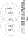
Figure 2 shows an example of a wireless communication system where two DL CCs may be configured on each site with a different transmit power, creating a region of cell coverage overlap but from a different CC associated with a different site; -
Figure 3A shows an example communications system in which one or more disclosed embodiments may be implemented; -
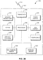
Figure 3B shows an example wireless transmit/receive unit (WTRU) that may be used within the communications system shown inFigure 3A ; -
Figure 3C shows an example radio access network and an example core network that may be used within the communications system shown inFigure 3A ; -
Figure 4 shows use of CCs to improve a WTRU received signal-to-interference plus noise ratio (SINR) at a wireless communication system cell boundary; -
Figure 5 is a conceptual illustration of rotation of sector antennas in one CC frequency; -
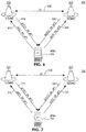
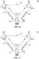
Figures 6-12 show various operation scenarios for a WTRU communicating with two different sites (eNBs); -
Figure 13 shows a geometrical layout of base stations; -
Figure 14 shows an optimized carrier-to-interference ratio (C/I) map for a CC with a power profile; -
Figure 15 is a graphical representation of a cumulative distribution function (CDF) of a non-normalized sum rate with equal power and unequal power; -
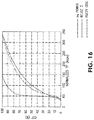
Figure 16 is a graphical representation of a CDF of a normalized sum rate assuming each WTRU uses 3 CCs; -
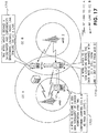
Figure 17 shows an example radio link failure due to mobility in a cooperative component carrier (CCC); and -
Figure 18 shows an example eNB access stratum protocol architecture. - When referred to hereafter, the terminology "wireless transmit/receive unit (WTRU)" includes but is not limited to a user equipment (WTRU), a mobile station, a fixed or mobile subscriber unit, a pager, a cellular telephone, a personal digital assistant (PDA), a computer, or any other type of user device capable of operating in a wireless environment. When referred to hereafter, the terminology "base station" includes but is not limited to a Node-B, an evolved Node-B (eNB), a site controller, an access point (AP), or any other type of interfacing device capable of operating in a wireless environment.
- A wireless communication system supporting higher data rates and spectrum efficiency may use a DL transmission scheme that is based on an orthogonal frequency-division multiple access (OFDMA) air interface. For the uplink (UL) direction, single-carrier (SC) transmission based on discrete Fourier transform (DFT)-spread OFDMA (DFT-S-OFDMA) may be used. The use of single-carrier transmission in the UL may be motivated by the lower peak-to-average power ratio (PAPR), as compared to multi-carrier transmission such as orthogonal frequency division multiplexing (OFDM).
- In order to further improve achievable throughput and coverage of wireless communication radio access systems, and in order to meet the international mobile telecommunications (IMT) advanced requirements of 1 Gbps and 500 Mbps peak data rates in the DL and UL directions respectively, several carriers may be aggregated in order to increase the maximum transmission bandwidth from 20 MHz up to 100 MHz, while supporting a flexible bandwidth arrangement feature. Each carrier, (i.e., component carrier (CC)), may have a maximum bandwidth of 20 MHz. CA is supported in the DL and the UL. Additionally, different CCs may have different coverage.
- The concept of CA using multiple CCs is relevant for wireless transmit/receive units (WTRUs) in a radio resource control (RRC) connected state. An idle WTRU will access the network via a single UL and DL carrier pair. CA may be supported on a single evolved Node-B (eNB). When CA is implemented, a cell is identified by a unique evolved universal mobile telecommunications system (E-UMTS) terrestrial radio access network (E-UTRAN) cell global identity (ECGI), and the cell corresponds to the transmission of system information in one CC. An anchor carrier is a carrier that provides system information, synchronization and paging for a certain cell. Furthermore, anchor carriers enable synchronization, camping, access and reliable control coverage in a heterogeneous network environment where interference coordination provides for at least one detectable (accessible) anchor carrier from a WTRU perspective. In that context, WTRU-specific anchor carriers may be considered to be a subset of the cell specific anchor carriers. A WTRU-specified anchor carrier may be used to carry multiple separate physical DL control channels (PDCCHs), each PDCCH corresponding to one CC.
- In certain wireless communication systems, the following three parameters may be signaled from higher layers to manage DL power allocation: Reference-signal-power, ρA and ρB. These parameters are used to determine cell specific DL reference signal (RS) energy per resource element (EPRE), the WTRU specific ratio of physical DL shared channel (PDSCH) EPRE over cell specific RS EPRE (ρA or ρB ), and the cell-specific ratio ρB /ρA. The eNB may determine the DL transmit EPRE, and the WTRU may assume that DL cell-specific RS EPRE is constant across the DL system bandwidth and constant across all subframes until different cell-specific RS power information is received. The DL reference-signal EPRE may be derived from the DL reference-signal transmit power given by the parameter Reference-signal-power provided by higher layers. The DL reference-signal transmit power is defined as the linear average over the power contributions of all resource elements that carry cell-specific reference signals within the operating system bandwidth. The ratio of PDSCH EPRE to cell-specific RS EPRE among PDSCH resource elements (REs) for each OFDM symbol may be denoted by either ρA or ρB according to the OFDM symbol index which are functions of ρA and ρB.
- In certain wireless communication systems, the Reference-signal-power, ρA and pB parameters may be provided by RRC peer messages in a PDSCH-Config information element (IE). There are two ways that a WTRU may obtain the PDSCH-Config IE. In idle mode, the WTRU may retrieve the default radio bearer configuration that includes the PDSCH-Config from system information block 2 (SIB2) when camping onto a cell. Upon transitioning from the idle mode to an active mode, the WTRU may use a stored default radio bearer configuration (including PDSCH-Config) to establish an initial RRC connection. Once the WTRU is in an active mode, an RRC Connection Reconfiguration message may be used by a network to provide the PDSCH-Config IE contained in a MobilityControlInfo IE to the WTRU. The PDSCH-Info may be provided along with physical cell ID and frequency, such that the network may control to where the WTRU may be connected during the active mode. In the case of a handover (HO), the physical DL shared channel (PDSCH)-Config of a target eNB is obtained by the serving eNB via X2 signaling while preparing to perform the handover.
-
Figure 1 shows an example of awireless communication system 100 including a WTRU 105 and two sites, (eNBs 110 and 115). Thesystem 100 is configured such that the WTRU 105 may aggregate CC bandwidth to increase data transfer rate. As shown inFigure 1 , the WTRU 105 communicates only with theeNB 110 via two separate CCs:CC 120 andCC 125. There may be specific limitations, (e.g., no granting mechanism, timing advance, channel quality indicator (CQI) signaling, positive acknowledgement (ACK)/negative acknowledgement (NACK) signaling, and the like), that prohibit a WTRU from receiving data on CCs from different sites. - For example,
Figure 2 shows one possible wireless communication system configuration where two DL CCs may be configured. Each site transmits on a CC with a different power, (i.e., either full power or reduced power). All of the WTRUs experience an acceptable level of signal-to-interference plus noise ratio (SINR) on a given CC.Figure 2 shows a scenario where the WTRU 105 is in the position ofWTRU 1, where bothCC 2 and CC3 may be accessible. If WTRU 105 is in the position ofWTRU 3, bothCC 1 andCC 4 may be accessible. When WTRU 105 is in the position ofWTRU 2, only one ofCC 1 orCC 2 is accessible. If, for example, WTRU 105 is accessingCC 2 onSite 1, a network radio resource management (RRM) entity (not shown) may determine whether or not a handover is to be performed to dropCC 2, in order to accessCC 1 onSite 1, rather than taking full benefit of the data throughput increase by using multiple CCs from a different site. - For example, if there are two UL CC (UC) frequencies per site,
UC frequency 1 andUC frequency 2, the path losses betweenWTRU 1 andSite 1 on each of these UL CC frequencies may be smaller than the path loss toSite 2. Similarly, forWTRU 3, the path loss toSite 2 may be more favorable. ForWTRU 2, however, the UL channel quality may be different than the DL signal quality. Thus, it may be possible that the path losses on bothUC frequency 1 andUC frequency 2 may be smaller toSite 1, even though the DL transmission on CC1 is received fromSite 2 due to the increased transmission power on CC1 bySite 2. -
Figure 3A shows anexample communications system 300 in which one or more disclosed embodiments may be implemented. Thecommunications system 300 may be a multiple access system that provides content, such as voice, data, video, messaging, broadcast, etc., to multiple wireless users. Thecommunications system 300 may enable multiple wireless users to access such content through the sharing of system resources, including wireless bandwidth. For example, thecommunications system 300 may employ one or more channel access methods, such as code division multiple access (CDMA), time division multiple access (TDMA), frequency division multiple access (FDMA), orthogonal FDMA (OFDMA), single-carrier FDMA (SC-FDMA), and the like. - As shown in
Figure 3A , thecommunications system 300 may includeWTRUs core network 306, a public switched telephone network (PSTN) 308, theInternet 310, andother networks 312, though it will be appreciated that the disclosed embodiments contemplate any number of WTRUs, base stations, networks, and/or network elements. Each of theWTRUs WTRUs - The
communications systems 300 may also include a base station 314a and a base station 314b. Each of the base stations 314a, 314b may be any type of device configured to wirelessly interface with at least one of theWTRUs core network 306, theInternet 310, and/or theother networks 312. By way of example, the base stations 314a, 314b may be a base transceiver station (BTS), a Node-B, an eNB, a Home Node-B (HNB), a Home eNB (HeNB), a site controller, an access point (AP), a wireless router, a remote radio head (RRH), and the like. While the base stations 314a, 314b are each depicted as a single element, it will be appreciated that the base stations 314a, 314b may include any number of interconnected base stations and/or network elements. - The base station 314a may be part of the
RAN 304, which may also include other base stations and/or network elements (not shown), such as a base station controller (BSC), a radio network controller (RNC), relay nodes, and the like. The base station 314a and/or the base station 314b may be configured to transmit and/or receive wireless signals within a particular geographic region, which may be referred to as a cell (not shown). The cell may further be divided into cell sectors. For example, the cell associated with the base station 314a may be divided into three sectors. Thus, in one embodiment, the base station 314a may include three transceivers, i.e., one for each sector of the cell. In another embodiment, the base station 314a may employ multiple-input multiple-output (MIMO) technology and, therefore, may utilize multiple transceivers for each sector of the cell. - The base stations 314a, 314b may communicate with one or more of the
WTRUs air interface 316, which may be any suitable wireless communication link (e.g., radio frequency (RF), microwave, infrared (IR), ultraviolet (UV), visible light, and the like). Theair interface 316 may be established using any suitable radio access technology (RAT). - More specifically, the
communications system 300 may be a multiple access system and may employ one or more channel access schemes, such as CDMA, TDMA, FDMA, OFDMA, SC-FDMA, and the like. For example, the base station 314a in theRAN 304 and theWTRUs air interface 316 using wideband CDMA (WCDMA). WCDMA may include communication protocols such as high-speed packet access (HSPA) and/or evolved HSPA (HSPA+). HSPA may include high-speed DL packet access (HSDPA) and/or high-speed UL packet access (HSUPA). - In another embodiment, the base station 314a and the
WTRUs air interface 316 using long term evolution (LTE) and/or LTE-Advanced (LTE-A). - In other embodiments, the base station 314a and the
WTRUs - The base station 314b in
Figure 3A may be a wireless router, a Node B, a HNB, a combination of an RNC and Node-B, an eNB, a HeNB, an RRH with an associated base station, or an AP, for example, and may utilize any suitable RAT for facilitating wireless connectivity in a localized area, such as a place of business, a home, a vehicle, a campus, and the like. In one embodiment, the base station 314b and theWTRUs WTRUs WTRUs Figure 3A , the base station 314b may have a direct connection to theInternet 310. Thus, the base station 314b may not be needed to access theInternet 310 via thecore network 306. - The
RAN 304 may be in communication with thecore network 306, which may be any type of network configured to provide voice, data, applications, and/or voice over Internet protocol (VoIP) services to one or more of theWTRUs core network 306 may provide call control, billing services, mobile location-based services, pre-paid calling, Internet connectivity, video distribution, and the like, and/or perform high-level security functions, such as user authentication. Although not shown inFigure 3A , it will be appreciated that theRAN 304 and/or thecore network 306 may be in direct or indirect communication with other RANs that employ the same RAT as theRAN 304 or a different RAT. For example, in addition to being connected to theRAN 304, which may be utilizing an E-UTRA radio technology, thecore network 306 may also be in communication with another RAN (not shown) employing a GSM radio technology. - The
core network 306 may also serve as a gateway for theWTRUs PSTN 308, theInternet 310, and/orother networks 312. ThePSTN 308 may include circuit-switched telephone networks that provide plain old telephone service (POTS). TheInternet 310 may include a global system of interconnected computer networks and devices that use common communication protocols, such as the transmission control protocol (TCP), user datagram protocol (UDP) and the Internet protocol (IP) in the TCP/IP suite. Thenetworks 312 may include wired or wireless communications networks owned and/or operated by other service providers. For example, thenetworks 312 may include another core network connected to one or more RANs, which may employ the same RAT as theRAN 304 or a different RAT. - Some or all of the
WTRUs communications system 300 may include multi-mode capabilities, i.e., theWTRUs WTRU 302c shown inFigure 3A may be configured to communicate with thebase station 314A, which may employ a cellular-based radio technology, and with thebase station 314B, which may employ an IEEE 802 radio technology. -
Figure 3B shows anexample WTRU 302 that may be used within thecommunication system 100 shown inFigure 3A . As shown inFigure 3B , theWTRU 302 may include aprocessor 318, atransceiver 320, a transmit/receiveelement 322, (e.g., an antenna), a speaker/microphone 324, akeypad 326, a display/touchpad 328, anon-removable memory 330, aremovable memory 332, apower source 334, a global positioning system (GPS)chipset 336, andperipherals 338. It will be appreciated that theWTRU 302 may include any sub-combination of the foregoing elements while remaining consistent with an embodiment. - The
processor 318 may be a general purpose processor, a special purpose processor, a conventional processor, a digital signal processor (DSP), a microprocessor, one or more microprocessors in association with a DSP core, a controller, a microcontroller, an application specific integrated circuit (ASIC), a field programmable gate array (FPGA) circuit, an integrated circuit (IC), a state machine, and the like. Theprocessor 318 may perform signal coding, data processing, power control, input/output processing, and/or any other functionality that enables theWTRU 302 to operate in a wireless environment. Theprocessor 318 may be coupled to thetransceiver 320, which may be coupled to the transmit/receiveelement 322. WhileFigure 3B depicts theprocessor 318 and thetransceiver 320 as separate components, theprocessor 318 and thetransceiver 320 may be integrated together in an electronic package or chip. - The transmit/receive
element 322 may be configured to transmit signals to, or receive signals from, a base station (e.g., the base station 314a) over theair interface 316. For example, in one embodiment, the transmit/receiveelement 322 may be an antenna configured to transmit and/or receive RF signals. In another embodiment, the transmit/receiveelement 322 may be an emitter/detector configured to transmit and/or receive IR, UV, or visible light signals, for example. In yet another embodiment, the transmit/receiveelement 322 may be configured to transmit and receive both RF and light signals. The transmit/receiveelement 322 may be configured to transmit and/or receive any combination of wireless signals. - In addition, although the transmit/receive
element 322 is depicted inFigure 3B as a single element, theWTRU 302 may include any number of transmit/receiveelements 322. More specifically, theWTRU 302 may employ MIMO technology. Thus, in one embodiment, theWTRU 302 may include two or more transmit/receive elements 322 (e.g., multiple antennas) for transmitting and receiving wireless signals over theair interface 316. - The
transceiver 320 may be configured to modulate the signals that are to be transmitted by the transmit/receiveelement 322 and to demodulate the signals that are received by the transmit/receiveelement 322. TheWTRU 302 may have multi-mode capabilities. Thus, thetransceiver 320 may include multiple transceivers for enabling theWTRU 302 to communicate via multiple RATs, such as UTRA and IEEE 802.11, for example. - The
processor 318 of theWTRU 302 may be coupled to, and may receive user input data from, the speaker/microphone 324, thekeypad 326, and/or the display/touchpad 328 (e.g., a liquid crystal display (LCD) display unit or organic light-emitting diode (OLED) display unit). Theprocessor 318 may also output user data to the speaker/microphone 324, thekeypad 326, and/or the display/touchpad 328. In addition, theprocessor 318 may access information from, and store data in, any type of suitable memory, such as thenon-removable memory 330 and/or theremovable memory 332. Thenon-removable memory 330 may include random-access memory (RAM), read-only memory (ROM), a hard disk, or any other type of memory storage device. Theremovable memory 332 may include a subscriber identity module (SIM) card, a memory stick, a secure digital (SD) memory card, and the like. In other embodiments, theprocessor 318 may access information from, and store data in, memory that is not physically located on theWTRU 302, such as on a server or a home computer (not shown). -
Figure 3C shows anexample RAN 304 and anexample core network 306 that may be used within thecommunication system 100 shown inFigure 3A . TheRAN 304 may employ an E-UTRA, a WCDMA or a GSM radio technology to communicate with theWTRUs air interface 316. TheRAN 304 may also be in communication with thecore network 306. - The
RAN 304 may includeeNBs RAN 304 may include any number of eNBs while remaining consistent with an embodiment. TheeNBs WTRUs air interface 316. In one embodiment, theeNBs eNB 340a, for example, may use multiple antennas to transmit wireless signals to, and receive wireless signals from, theWTRU 302a. - Each of the
eNBs Figure 3C , theeNBs - The
core network 306 shown inFigure 3C may include a mobility management gateway (MME) 342, a serving gateway (S-GW) 344, and a packet data network (PDN)gateway 346. While each of the foregoing elements are depicted as part of thecore network 306, it will be appreciated that any one of these elements may be owned and/or operated by an entity other than the core network operator. - The
MME 342 may be connected to each of the eNBs 342a, 342b, 342c in theRAN 304 via an S1 interface and may serve as a control node. For example, theMME 342 may be responsible for authenticating, managing and storing contexts of users of theWTRUs WTRUs MME 342 may also provide a control plane function for switching between theRAN 304 and other RANs (not shown) that employ other radio technologies, such as GSM or WCDMA. TheMME 342 may be a gateway general packet radio service (GPRS) support node. The S-GW 344 may be connected to each of theeNBs RAN 304 via the S1 interface. The S-GW 344 may generally route and forward user data packets to/from theWTRUs GW 344 may also perform other functions, such as anchoring user planes during inter-eNB handovers, triggering paging when DL data is available for theWTRUs GW 344 may be a serving general packet radio service (GPRS) support node (SGSN). - The S-
GW 344 may also be connected to thePDN gateway 346, which may provide theWTRUs Internet 110, to facilitate communications between theWTRUs - The
core network 306 may facilitate communications with other networks. For example, thecore network 306 may provide theWTRUs PSTN 308, to facilitate communications between theWTRUs core network 306 and thePSTN 308. In addition, thecore network 306 may provide theWTRUs networks 312, which may include other wired or wireless networks that are owned and/or operated by other service providers. - For the purpose of flexible deployment, certain wireless communication systems support scalable transmission bandwidths of either 1.4, 3, 5, 10, 15 or 20 MHz. These systems may operate in either frequency division duplex (FDD), time division duplex (TDD) or half-duplex FDD modes.
- In certain wireless communication systems, each radio frame (10 ms) may consist of 10 equally sized sub-frames of one (1) ms each. Each sub-frame may consist of two equally sized timeslots of 0.5 ms each. There may be either seven (7) or six (6) OFDM symbols per timeslot. Seven (7) symbols may be used with normal cyclic prefix length, and 6 symbols per timeslot in an alternative system configuration may be used with the extended cyclic prefix length. The sub-carrier spacing for these systems may be 15 kHz. An alternative reduced sub-carrier spacing mode using 7.5 kHz is also possible. A resource element (RE) may correspond to one (1) sub-carrier during one (1) OFDM symbol interval. Twelve (12) consecutive sub-carriers during a 0.5 ms timeslot may constitute one (1) resource block (RB). Therefore, with seven (7) symbols per timeslot, each RB may consist of 12x7=84 RE's. A DL carrier may consist of a scalable number of resource blocks (RBs), ranging from a minimum of 6 RBs up to a maximum of 100 RBs. This corresponds to an overall scalable transmission bandwidth of roughly one (1) MHz up to twenty (20) MHz. However, a set of common transmission bandwidths may be specified, (e.g., 1.4, 3, 5, 10 or 20 MHz). The basic time-domain unit for dynamic scheduling may be one sub-frame comprising two consecutive timeslots, (i.e., a resource-block pair). Certain sub-carriers on some OFDM symbols may be allocated to carry pilot signals in the time-frequency grid. A given number of sub-carriers at the edges of the transmission bandwidth may not be transmitted in order to comply with the spectral mask requirements.
- In the DL direction, a WTRU may be allocated by the eNB to receive its data anywhere across the entire transmission bandwidth, e.g., an OFDMA scheme may be used. The DL may have an unused direct current (DC) offset sub-carrier in the center of the spectrum.
- DL grants may be carried on a PDCCH. To support bandwidth aggregation, separate PDCCH coding, (e.g., a separate coding means that the PDCCH message for different CCs is encoded using a separate cyclic redundancy check (CRC) and a convolutional code), may be used to schedule DL resources with the following two options:
- 1) Option 1a: separate PDCCHs on each carrier may be used to schedule DL resources of that carrier; and
- 2) Option 1b: one PDCCH channel with separate coding on a given carrier may be used to schedule resources on multiple carriers by means of a carrier indicator (CI) field.
- A WTRU may be used to monitor a set of PDCCH candidates for control information in every non-discontinuous reception (DRX) subframe, where monitoring implies attempting to decode each of the PDCCHs in the set according to various monitored DL control information (DCI) formats.
- In certain wireless communication systems, the DCI formats a WTRU monitors may be divided into WTRU-specific search space and common search space. For WTRU-specific search space, the WTRU may monitor
DCI 0/1A and DCI, which may be semi-statically configured via RRC signaling, depending on the transmission mode. A PDCCH DL monitoring set may be defined, which comprises the DL CCs from the WTRU DL CC set on which a WTRU may be configured to receive scheduling assignments for cross-carrier scheduling. The WTRU may not have to perform blind decoding in DL CCs on which it is not configured to receive PDCCH, which reduces the probability of PDCCH false detection. - The WTRU may have one RRC connection with the network. The addition and removal of CCs may be performed without an RRC connection HO, as long as in case of removal, the CC being removed is not a special cell. A special cell may be primary component carrier (PCC) or the carrier that provides the control plane signaling exchange for the WTRU.
- Separate activation/deactivation may be allowed, either using medium access control (MAC) or physical (PHY) techniques. The CCs may exist in two states: 1) configured but deactivated; and 2) activated. In the DL, the WTRU may not receive PDCCH or PDSCH on deactivated CCs. On activated carriers, the WTRU may receive PDSCH, and PDCCH, if present. Further, the WTRU may not be used to perform CQI measurements on deactivated CCs. For the UL, an explicit activation/deactivation procedure may not be introduced.
- The network may configure mobility measurements to support WTRU inter-site handover based on reference signal received power (RSRP) or reference signal received quality (RSRQ). There are multiple ways to report neighbor cell measurements. For example, the WTRU may be configured to measure neighbor cell power on event or periodic reporting basis. The network relies on these neighbor cell measurements from the WTRU to make decisions on when to handover a WTRU to a different site within a given CC set. The network configures the WTRU such that it monitors, (e.g., makes measurements on), neighbor cells/sites in supported CCs to move the WTRU onto a CC that maintains the delivered service quality in support of WTRU mobility. The periodic measurements or measurement events (1× and 2×) may provide sufficient information to the network to select the appropriate CC that may be used to transmit data to a particular WTRU for each CC that may be used, and when such CC-specific (inter-site) handover (CSHO) occurs.
- In certain wireless communication systems, measurement events (1× and 2×) may be applicable for a WTRU configured with CA. These measurement events may be able to identify an individual CC for inclusion in a handover.
- When data is sent to a WTRU from multiple sites, the WTRU data may be present at multiple sites. Generally, this creates additional strain on the backhaul if done in the same fashion as for coordinated multi-point (CoMP) transmission, where multiple transmission points/sites coordinate their transmissions. This coordination may take several different forms such as coordination in scheduling, jointly transmitting data to a WTRU, and the like. In joint transmission, a complete copy of WTRU data may be made available at each site participating in CoMP transmissions. The architecture of multiple CCs supporting one evolved packet system (EPS) radio access bearer (RAB) may be maintained by a radio access network through medium access control (MAC) multiplexing and de-multiplexing. In this approach, data may be received at a serving eNB, and then copied and forwarded to all cooperating CCs/eNBs. This approximately doubles the backhaul loads per WTRU participating in CoMP joint transmissions involving two sites.
- The problem of cell-edge degradation due to interference limitations from neighboring cells in a
frequency reuse 1 deployment may be alleviated by: 1) manipulating the locations of the cell-edges in each CC in the system; and/or 2) allowing the WTRU to receive data from multiple sites, (e.g., data may be received from Site A oncarrier 1 and from Site B on carrier 2). In this way, the WTRU may be assigned to the site that provides the best throughput, (or other measure), for each CC that is in full aggregation of CCs, thereby creating the "fuzzy cell" concept where the notion of cell-edge does not apply as in a traditional cellular setting. As the WTRU is capable of receiving data on all CCs, a frequency reuse of one may be maintained. The WTRU may receive data on each available CC. The locations of the transmitting sites of the data for the WTRU may not be co-located in the system. - The cell boundary may be determined in part by the ratio of the largest signal power from any site to the sum of the power in the other signals (interference) and noise received at a given location and in any CC. The signal and interference powers received may be determined in part by the pathloss, antenna gain, and transmit power from each cell to the WTRU location. The manipulation of the cell-edge locations may then be performed using several different techniques.
- In one embodiment, the WTRU may establish a connection with a plurality of sites via respective DLs. The sites may include at least one of a Node-B, an eNB, a remote radio head (RRH) associated with a base station, or one of several sector transmit antennas of a Node-B or an eNB. Each DL may include at least one DL CC that operates on a frequency that is the same or different than one or more of the other DL CCs. The sites may manipulate their transmit power for a particular DL CC operating frequency, such that the distance from a particular one of the sites to its cell boundary becomes larger by increasing its transmit power on the particular operating frequency, and the distance from at least one of the other sites to its respective cell boundary becomes smaller by decreasing its transmit power on the particular operating frequency. Thus, a coverage overlap between different CC frequencies is created while maintaining a frequency reuse pattern of one.
- To illustrate this point,
Figure 4 shows the SINR of each of twoDL CCs site CCs - Additionally, the sector antenna patterns may be adjusted, (e.g., beamwidth, broadside angle, or other beam pattern shaping), so that transmit power density at different angles is controlled. The cell-edge locations may thus be manipulated by antenna patterns in a similar fashion as when the total transmit power was adjusted, except that now there is an angular component to affect on the location of the cell-edges, (i.e., changing the total power may change the power density in all departure angles by the same amount, whereas changing the antenna patterns may selectively change the transmit power density at different departure angles).
- For example, in a system with two carriers, where each site uses three sector antennas for each carrier frequency, a 3-sector pattern having 120 degrees per sector may be maintained within each carrier frequency, but one set of sector antennas may be rotated relative to the other. As shown in
Figure 5 , theellipses 505 may indicate sectors in the frequency ofCC 405 inFigure 4 , and theellipses 510 may indicate sectors in the frequency ofCC 410 inFigure 4 . In this way, the center of the sector beam in one CC frequency may be placed directly on top of the sector cell-edge in the other CC frequency. If the WTRU is able to connect to two CCs, it may effectively eliminate the perceived cell-edge in a substantial part of the system. - Among the CC in the aggregation, the cell-edge locations may be configured to have large separations, (i.e., the cell-edge locations in one CC may be geographically separated from the cell-edge locations in at least one or more of the other CCs in the aggregation).
- For example, in a cellular system that supports CA with multiple CCs, each site (eNB) may support all available CCs, whereby different CCs may use different transmit powers, as well as antenna patterns, so that the corresponding coverage may also be different per CC, (i.e., the cell-boundaries across all CCs may not be co-located). In a simple scenario with only two CCs, site numbers {1, 2, 3, ...} may be assigned. For CC1, a power usage pattern may be defined where all even numbered sites transmit at power P1 and all odd numbered sites transmit at power P2. For CC2, a power usage pattern may be defined where all even numbered sites transmit at power P3 and all odd numbered sites transmit at power P4. Antenna usage patterns may also be defined. For CC1, an antenna usage pattern may be defined where all even numbered sites transmit with pattern A1 and all odd numbered sites transmit with pattern A2. For CC2, an antenna usage pattern may be defined where all even numbered sites transmit with pattern A3 and all odd numbered sites transmit with pattern A4. In this example, for even numbered sites, antenna gain may be larger pointing North in CC1 and pointing East in CC2, while for odd numbered sites, antenna gain may be larger pointing South in CC1 and pointing West in CC2. The set of CCs used by a particular WTRU may originate from different transmission sites or cells. For example, if there are N CCs in the full aggregated bandwidth, then for each of the N CCs, the WTRU may be assigned to receive data from the transmission point that has the best signal quality, (e.g., signal-to-interference ratio (SIR)) for that CC frequency). Since different CCs may have different power usage patterns and different antenna usage patterns, the assigned CCs may originate from multiple transmission sites, (e.g., CC1 and CC2 from Site A, CC3 from Site B, and CC4 from site C).
- Several scenarios have been defined below to aid in the understanding of a CC cooperation network. These deployment scenarios are by no means exhaustive, and the scenarios presented here are representative scenarios only. One skilled in the art may appreciate and understand how to expand on these scenarios.
- The following nomenclature will be used: DL carrier frequency dlF1, dlF2...dlFn; UL carrier frequency ulF1, ulF2...ulFn; DL cooperative CCs DL-CCC1, DL-CCC2...DL-CCCn; UL CCs UL-CC1, UL-CC2...UL-CCn; and sites S1, S2....Sn.
- Scenario 1: DL CCCs; DL-CCC1 from site S1 (DL-CCC1-S1), and DL-CCC2 (reduced power) from site S2 (DL-CCC2-S2) on dlF1; DL-CCC3-S1 (reduced power) and DL-CCC4-S2 on dlF2; and UL CCs on ulF1, namely UL-CC1-S1 and UL-CC2-S2.
- Scenario 2: DL CCCs; DL-CCC1-S1 and DL-CCC2-S2 (reduced power) on dlF1; DL-CCC3-S1 (reduced power) and DL-CCC4-S2 on dlF2; and UL CCs on ulF1, namely UL-CC1-S1 and no UL carrier from site S2.
- Scenario 3: DL CCCs; DL-CCC1-S1 on dlF1 and no DL carrier from
site 2; and UL CCs on ulF1, namely UL-CC1 from S2 and no UL carrier from S1. - Scenario 4: DL CCCs; DL-CCC1-S1 and DL-CCC2-S2 (reduced power) on dlF1; DL-CCC3-S1 (reduced power) and DL-CCC4-S2 on same DL carrier frequency dlF2; UL CCs on ulF1, namely UL-CC1-S1 and UL-CC2-S2.
- Scenario 5: DL CCCs; DL-CCC1-S1 and DL-CCC2-S2 (reduced power) on dlF1; DL-CCC2-S1 (reduced power) and DL-CCC2-S2 on dlF2; UL CCs namely UL-CC1-S1 on ulF1 and UL-CC2-S2 on ulF2.
- Scenario 6: DL CCCs; DL-CCC1-S1 and no DL carrier from
site 2 on dlF1; and UL CCs on ulF1, namely UL-CC1-S1 and on ulF2 UL-CC2 from S2. - In order to efficiently support reception of data on CCs from multiple sites, a CC-specific handover (CSHO) mechanism may be implemented in addition to individual CC activation/deactivation and CC management. CSHO may also be implemented when a special cell has been changed. Alternatively, an individual CC activation or CC deactivation may be used instead of an RRC reconfiguration procedure. For example, as the WTRU moves about, it will encounter CC-specific cell edges at different locations. The quality (e.g., SINR) of only a subset of the CCs assigned to the WTRU will drop to a point that the transmitting site for that CC should be switched to another site to maintain a desired reception quality.
- In order for the network to effectively support CSHO, mobility measurement configuration/reporting per individual CC may be required. For example, WTRU may be configured to report neighbor cells/sites in all CCs (or a subset of CCs) that are part of the candidate set of CCs involved in a CC cooperation network. This may be implemented via an explicit modification of a monitored neighbor cell list, or via an implicit handling of cells detected by the WTRU by adding an undesired cell to a black list, or a configuration of a measurement on a specific CC of a network to ensure selection of a CC in the CC cooperation network to maintain the delivered service quality in support of WTRU mobility. In this way, the network may have sufficient information to determine the appropriate site that may be used to transmit data to a particular WTRU for each CC that may be used, and determine when CSHO may occur. This scenario may be fundamentally different from the usual handover, in that the WTRU remains in continuous contact with all sites, except for those being handed over to a new site, (if the WTRU does not already have a connection to it via a different CC), or when all of the CC connections from a site to the WTRU is terminated. Furthermore, the WTRU may remain in continuous connection with at least one site at all times, (i.e., the handover may be seamless).
- Measurements performed on each CC may be scheduled, or triggers set up, such that the measurement overhead to support CSHO may be reduced based on the time when a CC-specific inter-site handover is beneficial in one CC, as well as when CSHO to another CC is not likely to be beneficial. Therefore, a method to define measurements independently on each CC may be defined so that measurements may be performed and signaled when they may actually be needed to support a CSHO. For example, when the SINR in a particular CC drops below a threshold, (or the particular CC is otherwise determined to be a candidate for CSHO), a measurement to support the CSHO only in the particular CC is performed and reported to a network, and measurements in the other CCs may not be triggered unless they also are candidates for CSHO. CSHO in which a new site is not being added may already be connected to the site which is the target of the handover.
- In a CC cooperation network, instead of copying data to a multi-site as described by CoMP joint transmission, the data flow may be split so that complete copies of the WTRU's data is not sent to all of the sites involved in the CC cooperation transmission. For example, the data flow may be split before reaching any of the sites, such that only the data ultimately transmitted from a particular site is present at that site. Data transmitted from Site A may not need to be present at any site other than Site A. This potentially yields the most efficient solution to the data flow from a backhaul bottleneck point of view.
- Alternatively, a full copy of the WTRU's data sent to a particular site, (i.e., an anchor site, camping site, primary site, and the like), and then the particular site may only send a portion of the data to the remaining sites that will transmit data to the WTRU. For example, a complete data flow is sent to Site A. From Site A, a portion of the data is sent to Site B. Site B transmits all such data to the WTRU and Site A transmits only the portion of data not previously sent to Site B. Site A may be chosen to be the site that will transmit the most data to minimize the total backhaul load. CoMP joint transmission techniques may also be used on the carrier used by Site B, since both sites may have this data.
- The CC cooperation concept may be a possible low cost alternative to CoMP. However, they both may be deployed together and benefit from certain synergies. Depending on the suitability of CoMP, such techniques may be applied within one or more CCs. For example, if a WTRU is connected to two sites using different CCs, (
Site 1 for CC1 andSite 2 for CC2), and ifSite 1 is the primary camping site, the DL data fromSite 2 may be split fromSite 1. If the signal on CC2 fromSite 2 is a candidate for CoMP techniques, CoMP may be employed with no increase in backhaul loads, (e.g., CC2 fromSite 1 may be used to improve the reliability of the data transmission fromSite 2 under a CoMP framework). If the CC cooperation takes place betweenSite 1 andSite 2, there is no need to copy the data fromSite 2 toSite 1 again, since that data was originally forwarded fromSite 1. If the CC cooperation takes place betweenSite 2 and one or more sites other thanSite 1, (e.g., Site 3), then the data may be directly forwarded fromSite 1 toSites Site 2 toSite 3 under a CoMP framework. - While the CC cooperation network configuration may be deployed independent of CoMP, the CoMP set selection, (either the measurement set or the cooperating set, and the like), decisions may be influenced by the CCC set, on a condition that the camping site already has a full WTRU data set. An additional input to a CoMP set determining algorithm may be defined to permit CoMP set decisions to be performed with the knowledge of the CCC configuration. For example, CC1 may be determined to be a CoMP candidate, and
Sites Site 2 orSite 3 to the CoMP set may normally not consider the CCC configuration, and either site may be chosen. However, ifSite 3 is known to have a copy of the WTRU's data that may be part of a CoMP joint transmission, it may be chosen rather thanSite 2. By creating the interface from the CCC configuration to the CoMP set determination algorithm, a better selection may be made. - The configuration of a network with the CCC feature may be performed and adaptively changed by exchanging certain information among the cooperating sites. By exchanging such information as the number and bandwidth of CCs, transmission power levels on the CCs, antenna patterns used in the CCs, system load on each CC, and the like, the cooperating sites may try to adjust the transmission parameters. In one embodiment, the transmission parameters may be determined in a central controller after collecting all possible information from the cooperating transmission points. The central controller may be responsible for the configuration of the transmission parameters of a cluster of transmission points. Alternatively, the transmission parameters may be autonomously determined by the transmission points by using the information exchanged among these points. In this case, the decision processes used in the sites may go through several iterations until a stable set of parameters have been determined in each site. The WTRUs may need to feed back information to the serving transmission points, (e.g., the level of interference created by a neighbor transmission point on a CC, path losses and/or level of received power from the transmission points on each CC, and the like).
- As an example, some sites may employ a reuse factor of 3, (i.e., only transmit on one of the CCs of 1∼3); while some sites may have a reuse factor of one, (i.e., transmit on all three CCs). The reuse scheme may be dynamic so that higher order schemes may be employed when traffic is light, or when there is a large number of high QoS users, such that when demand increases, the reuse factor may be reduced. This feature may reduce the power consumption of base stations when the system load requirement is not high by turning off power on some of the CCs. As another example, one transmission site may report the excessive interference level its WTRUs experience in one of the CCs, and may have the neighboring cells reduce the transmission power on that CC.
- Semi-static inter-CC interference coordination strategies may be required to allow adaptive update and configuration, and may include an extension of the standardized relative narrowband transmit power (RNTP) indicator, high interference indicator (HII) and overhead indicator (OI) for each CC. The RNTP indicator may indicate the maximum DL transmit power per physical resource block (PRB). Similarly, for the UL, HII and OI may inform neighboring eNBs of a UL usage plan and interference plus noise measurements, respectively. CCCs may be dynamically re-provisioned and/or added/removed to cover holes or mitigate interference based on these and other measurements and indicators.
- Other messages exchanged among the transmission sites may include measurements, (e.g., number of active WTRUs and the like), allow adaptive updates for load-balancing across CCs and switch on and off those CCs that are not needed for traffic for interference reduction purposes, (in particular if some CCs are used in home-eNBs). Mobility robustness improvements may be enabled by tracking number of radio link failures (RLFs) and HOs, power restrictions or preferred PRBs and the like.
- Another factor that may affect performance is a random access channel (RACH) configuration, which may affect RACH collision probability, and hence making this a significant factor in call setup delays, data resuming delays and handover delays. This also may affect the call setup success rate and handover success rate. UL CC assignment for WTRUs in the range of a CCC may not be identical to DL CCC, and adaptive CCC configuration and UL association may need to consider RACH load, UL interference, and impact to RACH performance/usage in each cell.
- Under a fuzzy cell context, in order to create a cell deployment with a non-uniform power across different CCs and sites, the DL EPRE per CC and per site may be varied in accordance with the surrounding environments. In order to derive a DL reference-signal EPRE, and PDSCH EPRE, the WTRU may determine the DL Reference-signal-power, as well as ρA and ρR. As a consequence, to support a fuzzy cell, it may be required that these three parameters are provided per CC per site by the network.
- Before a fuzzy cell WTRU establishes connections to multiple eNBs for DL data transmission, the WTRU may receive power control information from the SIB2 of a DL-SCH channel when an RRC connection is established, and from a mobility control information IE carried in a RRC reconfiguration message in a connection mode. During and after the WTRU sets up multi-eNB connections, it may continue to rely on mobility control information transmitted as a part of the RRC reconfiguration message to obtain multiple eNB and CC power control information.
- The DL power control parameters, along with associated cell information about one eNB, may either be transmitted via the eNB's RRC reconfiguration message, or it may be forwarded via X2 signaling to another eNB, and then signaled to the WTRU. In the latter case, the configuration information may designate a maximum number of sites that a WTRU may be connected to at any given time.
- To improve system efficiency and operability, a cross-carrier scheduling mode may be implemented, whereby a PDCCH may be located in the first n OFDM symbols with n less than or equal to four (4), and with the earliest data transmission start being at the same OFDM symbol as the control signaling ends. This may enable support for micro-sleep and reduce buffering and latency. The physical control format indicator channel (PCFICH) may be used by the eNB to inform the WTRU about the number of OFDM symbols (1, 2, 3, or 4) used for the PDCCH in a sub-frame. This channel may comprise 32 bits, which may be cell-specific scrambled prior to modulation and mapping.
- The concept of anchor carrier will now be presented in a fuzzy cell context. An anchor carrier may be defined per site. If a WTRU is connected to more than one site, the WTRU may have multiple anchor carriers defined at any given instant. The definition of anchor carrier may be in addition to a primary CC (PCC). One of the anchor carriers may be the PCC for the WTRU. All UL control channel feedback on a physical UL control channel (PUCCH) may only be defined for the UL anchor carrier for that site.
- In a fuzzy cell configuration, an anchor carrier may denote the UL CC which carries all control channel feedback on the PUCCH for that site. All other secondary cells from that site may only support a shared data channel or physical UL shared channel (PUSCH). Thus, a difference between the anchor carrier definition and the PCC may be that there is only one PCC where there may be as many anchor carriers as there are sites that the WTRU may be connected to. It may not always be required to define an anchor carrier per site, especially in scenarios where there is no UL CCC defined for that site. For the site where a PCC is defined, an anchor carrier may be the same CCC as the PCC.
- In one embodiment for fuzzy context, a WTRU operating in a cross-carrier scheduling mode may read a control format indicator (CFI) via a PCFICH on the anchor carrier for that site. In addition, to indicate the starting position of PDSCH reception for cross-scheduled CCC, RRC signalling may be used to configure CFI for cross-scheduled CCC originating from that site. The WTRU may read the CFI from a dedicated RRC signaling that is transmitted in the anchor carrier and determine the starting position of PDSCH reception in the corresponding cross scheduled CCC.
- In another embodiment for fuzzy context, a WTRU operating in cross-carrier scheduling mode may read the CFI via a PCFICH on the primary CC (PCC). Cross-scheduling information for all CCCs from one or more eNBs may be sent to the eNB where the PCC is defined. To indicate the starting position of PDSCH reception for all cross-scheduled CCCs, (including those CCCs not originating from this eNB), RRC signaling may be used to configure CFI for all cross-scheduled CCCs. The WTRU may read CFI from dedicated RRC signalling that may be transmitted in the anchor carrier, and determine the starting position of PDSCH reception in the corresponding cross-scheduled CCCs.
- Since all CCs may originate from the same eNB, introducing only a CI field may be sufficient in option 1b to indicate which CC the grant may be for. In a fuzzy cell, some of the WTRU's data may originate from one eNB, while other data may originate from other eNBs. Since the WTRU may know which eNB it is connected to for a particular CC, and the WTRU may not connect to more than one eNB simultaneously with that CC in a non-CoMP mode, (even in CoMP mode, there may be only one grant for one CoMP set), the CI field may be sufficient in the fuzzy cell by only indicating which CC the grant may be for, but the CI field may have to be transmitted from each anchor carrier of the WTRU, as opposed to a PCC.
- This type of cross-eNB grant transmission may include the transmission of a grant from one eNB via X2 signaling to another eNB, and may further include the transmission by that eNB's PDCCH channel. In some deployments, transmission of the grants from one eNB to another eNB may not occur due to the delay incurred over an X2 interface. Thus, DL grants may be transmitted via the PDCCH channels from the same eNB as the corresponding data channels on the corresponding anchor carrier. When option 1b is implemented in a fuzzy cell context, the PDCCHs on a given carrier with separate coding may be used to schedule resources on multiple carriers from the same eNB anchor carrier, if cross-eNB grant transmission is prohibited due to a large X2 delay.
- In summary, a fuzzy cell capable WTRU may have at least one PDCCH per eNB from which it may receive data, and the actual configuration may depend on the CC types and system setup. For example, if a WTRU is connected to
eNB 1 with CC1 and CC2,eNB 2 with CC3 and CC4, and the anchor carrier from eNB1 is CC1, and the anchor carrier from eNB2 is CC3, the following configurations for DL granting may be used. - If all of the CCs are backward compatible, the WTRU may be configured to use option 1a, with each CC containing its own PDCCH for grant transmission.
- If all of the CCs are non-compatible, the WTRU may be configured to use option 1b, with one PDCCH (with separate coding) on its anchor carrier CC1 from eNB1 to carry grants for CC1 and CC2, and one PDCCH from
eNB 2 on its anchor carrier CC3 to carry grants for CC3 and CC4. - Alternatively, a hybrid scheme may be used: option 1a for eNB1 and option 1b for eNB2, and the like, or vice versa, depending on the CC types.
- In another embodiment, if an X2 interface delay between different eNBs is very small, grants from one eNB may be forwarded via the X2 interface to another eNB, and then may be transmitted via that eNB's PDCCH channel using a PCC with option 1b by using a CI field. This may provide for more efficient scheduling in the network, along with better interference management opportunities. To achieve a low X2 interface delay, a new GPRS tunneling protocol (GTP) tunnel may be created on an X2 interface for this purpose. An X2 interface for a user plane may use a GTP, whereas an X2 interface for a control plane may use a stream control transmission protocol (SCTP). In some implementations, the SCTP may be slower than the GTP, even though the SCTP may be a connection oriented protocol that transports data in independent streams, (as compared to TCP). It may be advantageous to use an X2 GTP tunnel in such scenarios. Any proprietary mechanisms may also be used to reduce latency on an eNB-eNB interface. Furthermore, since the WTRU may know which eNB a particular CC is connected to, it may not be necessary to specify the site information in a grant transmission.
- A WTRU may monitor a set of PDCCH candidates from the same site for control information in every non-DRX subframe, where monitoring may imply an attempt to decode each of the PDCCHs in the set according to all of the monitored DCI formats. In a fuzzy cell context, a WTRU may be required to monitor multiple sets of PDCCH candidates for control information in every non-DRX subframe, (i.e., one set for each site the WTRU is going to receive data from). A DL PDCCH CC monitoring set may be extended across multiple sites, or the WTRU may maintain two PDCCH CC monitoring sets.
- For WTRU-specific search space, a WTRU may monitor
DCI 0/1A and a DCI which may be semi-statically configured via RRC signaling, depending on the transmission mode. For a fuzzy cell WTRU which may be connected to multiple sites, the DCI formats in WTRU-specific search space from one site may either be directly signaled via RRC signaling from that site, or the information may initially be forwarded to the main serving site through X2 signaling, and then transmitted through the main serving site's RRC signaling. - The deployment of the CCC concept in the UL signaling may occur, since there may be no equivalent CCC concept in the UL. Specifically, the best UL CC to use in terms of quality of reception, (or required power to achieve particular UL quality), may not be influenced by the CCC configuration. Thus, the site that may best receive the UL control messages, (ACK/NACK, CQI, and the like), from the WTRU may be different than the site from which the WTRU received the corresponding DL data. For ACK/NACK signals. For example, the ACK/NACK may be signaled to the site that has the best pathloss, (or long term pathloss), with a UL power control appropriate for that site. The receiving site may then forward the ACK/NACK to the site transmitting the DL data so that retransmission may be scheduled. Alternatively, the UL Tx power may be adjusted so that the UL ACK/NACK may be monitored by the same site providing the DL data.
- In a scenario where the WTRU is connected with multiple eNBs (or sites) with one or more UL CCs to each site, the corresponding UL anchor carrier associated with the eNB may be used for sending UL control information (UCI) to each site. In another embodiment, all UCI may be sent using the PCC, and then relevant control information for each eNB may be forwarded from the eNB servicing the UL PCC using the X2 interface. The UL control information may be forwarded on an X2 interface based on the delay incurred over the X2 interface, and may be specific to X2 interface implementations.
- In situations where an X2 interface delay is tolerable, the WTRU may be assigned a UL CC to only one site. In such a scenario, all UCI may be sent on this UL CC and may be forwarded to the other site using an X2 interface. Furthermore, it may be desirable to use a GTP over the X2 interface, as opposed to an SCTP, or vice-versa, depending on implementations of the X2 interface.
- Similar solutions may be applied to CQI-type signals. Alternatively, the CQI reporting schedules between sites participating in a CCC may be coordinated so that CQI transmission from a WTRU to multiple sites may occur on the same radio resources. Furthermore, the CQI information for the multiple sites, (i.e., the multiple DL CCs), may be coded into a single message monitored by both sites. Thus, both sites may have increased SINR because the inter-cell interference for the CQI report may be reduced, and both sites may monitor the same message from a single WTRU, rather than having multiple UL messages, (possibly from different WTRUs), being transmitted in the same radio resources to multiple sites. Since the WTRU may not send a separate message to each site, these separate messages may not interfere with each other. Furthermore, since both sites may know each others CQI reports, any exchange of CQI messages between the sites using backhaul may not be needed, (e.g., to help manage data flow splitting).
- UCI may be piggybacked when a simultaneous configuration of a PUCCH and PUSCH is not implemented. In one embodiment, UCI may be transmitted on each anchor carrier if the WTRU has a PUSCH transmission configured on the anchor carrier(s). In another embodiment, if an X2 interface delay is acceptable, all UCI may be sent on a UL PCC. In case the WTRU has a PUSCH transmission on a secondary cell that is not available on an anchor carrier or PCC, the WTRU may transmit the UCI to each site on their corresponding secondary CCs (SCCs).
- Pairing or association between UL and DL carriers may be provided by the network as part of broadcast information or dedicated RRC signaling. If corresponding UL carrier frequency information is absent, such information may be derived from a default Tx channel, (carrier center frequency), to a receive (Rx) channel, (carrier center frequency), separation.
- Some aspects related to UL signaling, UL power control and UL grants are explained below using different scenarios, whereby the DL carrier frequency is dlF1, dlF2...dlFn, the UL carrier frequency is ulF1,ulF2...ulFn, the DL CCC is dlCCC1, dlCCC2...dlCCCn, the UL CC is ulCC1, ulCC2...ulCCn, and the site is S1, S2...Sn.
- If not particularly specified in RRC signaling, the default pairing of a DL CC and a UL CC, which may be equivalent to the pairing of a DL carrier frequency and a UL frequency, may be based on the duplex distance, (i.e., Tx-Rx frequency separation for each operative frequency band).
- The network may have the ability to specifically signal a pairing of a DL CC and a UL CC in accordance with a different rule, whereby the difference between the DL CC and the UL CC is not the duplex distance. Since the duplex filter may be built with the specification of the duplex distance, a frequency distance between the DL and UL CCs of one pair may not cause filtering performance degradation.
- The pairing of a DL CC and a UL CC may dictate the DL and UL association of a range of operations. For example, a pairing of dlCCC1 and ulCC1 may imply that the UL grant of ulCC1 may be transmitted in dlCCC1, an ACK/NACK associated with a hybrid automatic repeat request (HARQ) transmitted on dlCCC1 may be carried on ulCC1, and the like.
-
Figures 6-12 show various operation scenarios for a WTRU that may communicate with two different sites (eNBs). Details presented below that are associated withFigure 6 may apply to all other scenarios unless alternate details are explicitly mentioned in each of the respective scenarios. -
Figure 6 shows awireless communication system 600 including aWTRU 605 and two Sites (eNBs) S1 and S2. TheWTRU 605 may be connected with site S1 via a DL 610 (dlCCC1 on dlF1), and via a UL 615 (ulCC1 on ulF1). Thesame WTRU 605 may be connected with Site S2 via a DL 620 (dlCCC2 on dlF2), and via a UL 625 (ulCC2 on ulF2). AnX2 interface 630 may allow Sites S1 and S2 to communicate with each other. - In the scenario shown in
Figure 6 , theDL 610 may carry the pCell, and theUL 615 may be the primary UL CC where UCI may be transmitted via a PUCCH separately. In one embodiment, theDL 620 may be configured as the sCell and theUL 625 may only carry PUSCH where UCI is piggybacked in a PUSCH. - In this UCI piggyback scenario, when simultaneous PUCCH and PUSCH are not configured, the UCI, (e.g., ACK/NACK and channel state information (CSI)), may be transmitted in a single UL carrier selected according to the following rules. When the
WTRU 605 has a PUSCH transmission on the primary cell, the UCI may be transmitted over the primary cell. When theWTRU 605 has a PUSCH transmission on one or more secondary cells, but not on the primary cell, the UCI may be transmitted over one secondary cell. - In one alternative embodiment, UCI for the
DL 620 may be sent over theX2 interface 630. The decision of whether to send UCI either piggybacked on an sCell PUSCH, or to send it over theX2 interface 630, may depend on the implementation and may be influenced by several factors, such as delay over theX2 interface 630, whether cross-carrier scheduling may be performed in a pCell for an sCell to take advantage of better inter-cell interference management, and the like. - Another option may be to employ the anchor carrier that transmits PUCCH to each site. The
UL 615 may be the anchor carrier for Site S1 and theUL 625 may be the anchor carrier for Site S2. Thus, the UCI intended for Sites S1 and S2 may be sent on its respective anchor carrier. - The PUSCH transmission power may be set as follows:

WTRU 605 based on RSRP measurement and signaled RS eNB transmission power, Δ MCS is a modulation and coding scheme (MCS)-dependent power offset set by the eNB, P0_PUSCH is a WTRU-specific parameter, (partially broadcasted and partially signaled using RRC), α is cell-specific parameter, (broadcasted on a broadcast channel (BCH)), Δ i are closed loop power control (PC) commands signaled from the eNB (S1, S2) to theWTRU 605, and the function f ( ) indicates whether closed loop commands are relative accumulative or absolute. f ( ) is signaled to theWTRU 605 via higher layers. - The parameter PL is the path loss estimate calculated in the
WTRU 605 as PL = referenceSignalPower - higher layer filtered RSRP. When multiple UL CCs are used for UL transmission, a path loss estimate for each UL CC may be used. In one embodiment, the path loss PL0 on one of the DL CCs, for example, a CC that was defined as the anchor may be estimated. For a given UL CC k, the path loss estimate may be computed as:
- The UL power control mechanism may depend on the power amplifier (PA) configuration of the
WTRU 605, the number of UL CCs, and whether there is a single PA used for all UL CCs, or possibly one PA for each CC, or one PA for several CCs, the association of the DL CCs and/or the transmitting sites to the UL CCs and determination of the open loop component of the UL power control, the signaling from the network to manage the closed loop component of the UL power control, and the differences of power control mechanisms for data and control transmission. - The association of the UL CCs to the sites may be such that all UL CCs may or may not be associated with one site. In another possible approach where the sites may cooperate, a UL CC may be associated to a "virtual" site.
- With the fuzzy cell concept, transmission on different DL CCs may be generated on physically separated sites. The path losses from these sites (S1, S2) to the
WTRU 605 may be significantly different. Therefore, a separate path loss may be estimated for each of the transmission sites. The path loss for a given transmission site may be estimated by using one of the DL CCs used by that site for transmission, for example, one that may have been defined as the anchor carrier for that transmission site. Alternatively, a linear combination of the path losses estimated on some or all of the DL CCs may be used by that site. - The path loss estimate used in the UL power control for a specific UL CC may depend on the configuration of UL CCs. In accordance with one embodiment, PL(k) may be used for the power control of a UL CC, and may be determined by the path loss estimate of the site with which the UL CC is associated. Specifically:

- In the fuzzy cell concept, separate PDCCHs may be transmitted from transmission sites. Within the DL CCs used by a specific transmission site for transmission, a separate PDCCH per DL CC may be sent to schedule transmission resources on that carrier. Alternatively, a PDCCH transmitted on one DL CC may schedule resources on another DL CC with the use of a carrier indication field.
- Similarly, an UL grant that allocates the resources for transmission on a specific UL CC may be transmitted by the transmission site which the UL CC is associated with. There may be an association with the UL CC to one of the DL CCs used for transmission by that site. This DL CC may be used to transmit the UL grant. The transmit power control (TPC) command may also be carried in the same component carrier as the UL grant. The ACK/NACK due to the UL transmission may be also carried on this DL CC.
- In an alternative embodiment, the UL grant for a UL CC may be transmitted by a different site than the site which the UL CC is associated with. In this case, the UL grant may include a UL CC, (and transmission site), indication field to indicate to the
WTRU 605 which UL carrier the resource allocation information may be for. The TPC command may also be carried similarly. In this case, the transmission sites may need to exchange information, such as CSI parameters, (including CQI/precoding matrix indicator (PMI)/rank indicator (RI) and the like), power control parameters (e.g., TPC) and the like, so that scheduling decisions may be implemented. - UL control data may include an ACK/NACK due to the DL transmission, channel state information (CSI) including CQI/PMI/RI, channel quantization information, and the like, which may be used for scheduling decisions, scheduling requests, and the like. UL control data may be carried in a UL control channel (PUCCH) or PUSCH.
- For PUCCH transmission, the PUCCH may be mapped to one UL CC. This UL CC may be selected such that the path loss to the receiving site is the smallest among all possible sites/carriers. In this case, the PUCCH power control may be adjusted by using the parameters for this site, (e.g., the path loss, and the like). PUCCH information may be mapped to several UL CCs where each UL CC may be associated with a different transmission site. The PUCCH in one UL CC carries the control data for the corresponding transmission site. PUCCH power on a specific UL CC is adjusted such that PUCCH is reliably received at the corresponding transmission site.
- In addition, UL power control associated with CA may be implemented using various parameters that are specific to the
DLs DLs - The following UL power and grant related aspects may be applicable for the fuzzy cell concept. TPC in a UL grant may be applied to a UL CC for which the grant applies, (i.e., a TPC sent in a UL grant from the
DL 610 may be applied to theUL 615 in site S1. With CIF based cross-carrier scheduling, the TPC field in the UL grants configured with CIF may control the power of the PUSCH and SRS transmissions in the UL CC that may not be linked with the DL CC in which the grant is transmitted. Thus, with cross-carrier scheduling in this scenario, theDL 610 may send TPC to regulate UL power of theUL 625 if necessary. However, given the cross-site configuration, any such joint-scheduling effort may require data exchange over theX2 interface 630. The benefit may be reducing overhead from signaling on theDL 620 as much as possible, and in utilizing theDL 620 for data use. In the case of theDL 620 being an extension CC where no PDCCH may be present, the cross-carrier UL power control may become necessary. - TPC in DL grant may be applied to a UL CC for which the ACK/NACK may be transmitted, (i.e., a TPC command sent in a DL grant from the
DL 610 may be applied to theUL 615 in Site S1). - TPC in
DCI format 3/3A may be applied to the UL CC using a combination of a TPC index in RRC signaling and TPC-PUSCH-radio network temporary identifier (RNTI). This configuration may be extended for cross-carrier UL power control TPCtransmission using DCI 3/3A. A power headroom report (PHR) may include CC-specific reports for PUCCH/ PUSCH. SinceType 2 PHR may only be valid for pCell, in this scenario, presuming theUL 615 is the primary cell (pCell) UL and theUL 625 is the secondary cell (sCell) UL,Type 1 PHR may be used for theUL 615 andType 2 PHR may be used for theUL 625. Therefore, there may be instances that theWTRU 605 simultaneously transmitsType 1 andType 2 PHRs. - Maximum power scaling may be conducted per channel with priority on PUCCH power followed by PUSCH including UCI and then PUSCH. In this scenario, a new priority may be introduced that is related to the site configuration. For example, instead of applying the priority based on the channel, the UL connected to one site may be scaled down, regardless of what channels are carried. This may be a simple radio frequency (RF) attenuation on one frequency in this scenario, instead of going through the scaling calculation in baseband. Timing advance may be sent from two sites based on the reception of the
UL 615 at Site S1 and the reception of theUL 625 at Site S2. -
Figure 7 shows awireless communication system 700 including aWTRU 705 and two Sites (eNBs) S1 and S2. TheWTRU 705 may be connected with Site S1 via a DL 710 (dlCCC1 on dlF1), and via a UL 715 (ulCC1 on ulF1). Thesame WTRU 705 may be connected with Site S2 via a DL 720 (dlCCC2 on dlF1), and via a UL 725 (ulCC2 on ulF2). AnX2 interface 730 may allow sites S1 and S2 to communicate with each other. - In the scenario shown in
Figure 7 , the difference between dlF1 and ulF2 may be less than the duplex distance. In all scenarios, a fuzzy cell configuration may implement a common scheduler that performs scheduling of resource of carriers belonging to different sites based on CSI reported with respect to each site and exchanged via theX2 interface 730 and consolidated at the common scheduler. In this scenario, as theDLs DL DL 710 may not be scheduled on theDL 720 to avoid interference. Unlike insystem 700, theDLs system 600 ofFigure 6 . Except for this restriction, the scenario ofFigure 7 may be similar to the scenario ofFigure 6 in terms of its UL aspects. -
Figure 8 shows awireless communication system 800 including aWTRU 805 and two Sites (eNBs) S1 and S2. TheWTRU 805 may be connected with Site S1 via a DL 810 (dlCCC1 on dlF1), and via a UL 815 (ulCC1 on ulF1). Thesame WTRU 805 may be connected with Site S2 via a DL 820 (dlCCC2 on dlF2), and has no associated UL CC. AnX2 interface 825 may allow Sites S1 and S2 to communicate with each other. - All feedback and HARQ information corresponding to
DL 820 may be multiplexed onto theUL 815, transmitted to Site S1 and subsequently forwarded to Site S2 via theX2 interface 820. Power control and timing advance may be regulated by Site S1 via theDL 810. The latency introduced by X2 interface information forwarding may not affect the HARQ/CSI time line, because the common scheduler is aware of in which sub-frame Site S2 may transmit a certain transport block (TB) in theDL 820, and instruct Site S1 to expect the associated ACK/NACK in the sub-frame that is four sub-frames later. Thus, the HARQ transmission on theDL 820 may initiate at Site S2 and terminate at Site S1. In the case of a NACK, Site S1 may inform Site S2 regarding the retransmission in sufficient time so that theWTRU 805 receives the retransmission exactly eight sub-frames later. - The multiplexing of ACK/NACK associated with both the
DLs UL 815 may require additional signaling from Sites S1 to S2 in order for proper operation of theDL 820 over theX2 interface 825. TheWTRU 805 may receive UL grants for theUL 815 from theDL 810. The common scheduler, (likely residing at site S1 inFigure 8 ), may readily have CSI associated with both Sites S1 and S2, and may perform a common pool scheduling and apply cross-carrier scheduling in PDCCH using CIF for DL resource scheduling. -
Figure 9 shows awireless communication system 900 including a WTRU 905 and two Sites (eNBs) S1 and S2. The WTRU 905 may be connected with Site S1 via a DL 910 (dlCCC1 on dlF1), and via a UL 915 (ulCC1 on ulF1). The same WTRU 905 may be connected with Site S2 via a DL 920 (dlCCC2 on dlF1), and may have no associated UL CC. AnX2 interface 925 may allow Sites S1 and S2 to communicate with each other. This scenario may be similar to thesystem 800 ofFigure 8 in terms of UL configuration, and may be similar to thesystem 700 ofFigure 7 in terms of DL configuration. -
Figure 10 shows awireless communication system 1000 including aWTRU 1005 and two Sites (eNBs) S1 and S2. TheWTRU 1005 may be connected with Site S1 via a DL 1010 (dlCCC1 on dlF1), and via a UL 1015 (ulCC1 on ulF1). Thesame WTRU 1005 may be connected with Site S2 via a DL 1020 (dlCCC2 on dlF2), and theUL 1015. AnX2 interface 1025 may allow Sites S1 and S2 to communicate with each other. - All feedback and HARQ information corresponding to the
DL 1020 may be multiplexed onto theUL 1015. Using the UL scheduling information provided by Sites S1 to S2 via theX2 interface 1025, Site S2 may demodulate and decode theUL 1015 accordingly. The Site S2 may have the ability to aperiodically trigger a sounding reference signal (SRS) for UL channel estimation as Site S1 does, and also may have the ability to schedule CSI information separately from Site S1. The common scheduler may need to coordinate the UL resource allocation between Sites S1 and S2. - In addition, two sets of power control and timing advance mechanisms may be employed at two sites intended for one WTRU, and either selectively or collectively this information may be evaluated and reconciled. For example, during the period where the Site S1 is subjected to a satisfactory UL SINR from the
WTRU 1005, more RBs on theUL 1015 may be scheduled for the Site S1. This may selectively transmit to the Sites S1 or S2 in a different period mat equate to a type of time division multiplexing (TDM) applied to theUL 1015. - Furthermore, in the case of power control, typically the UL SINR at one site (eNB) may be taken into account, whereas in a fuzzy configuration, the common scheduler may look for a type of balance between UL SINR at the Site S1 and the SINR at the Site S2, and may generate one common set of TPC bits accordingly.
- Due to the different propagation paths, the sub-frame of the
UL 1015 may arrive at the Sites S1 and S2 at different time instances and, in turn, may lead to two different timing advance values TA1 and TA2. Depending on the difference between TA1 from S1 and TA2 from S2, the selective and collective approaches may be applied. The usage of theUL 1015 may be optimized to reach Sites S1 and S2 simultaneously or alternatively. -
Figure 11 shows awireless communication system 1100 including aWTRU 1105 and two Sites (eNBs) S1 and S2. TheWTRU 1105 may be connected with Site S1 via a DL 1010 (dlCCC1 on dlF1), and via a UL 1115 (ulCC1 on ulF1). Thesame WTRU 1105 may be connected with Site S2 via a DL 1120 (dlCCC2 on dlF1), and theUL 1115. AnX2 interface 1125 may allow Sites S1 and S2 to communicate with each other. This scenario may be similar to thesystem 1000 ofFigure 10 in terms of UL configuration, and similar to thesystem 700 ofFigure 7 in terms of DL configuration. -
Figure 12 shows awireless communication system 1200 including aWTRU 1205 and two sites (eNBs) S1 and S2. TheWTRU 1205 may be connected with Site S1 via a DL 1210 (dlCCC1 on dlF1) and may have no associated UL. Thesame WTRU 1205 may be connected with Site S2 via a UL 1215 (ulCC2 on ulF1), and may have no associated DL. AnX2 interface 1220 may allow Sites S1 and S2 to communicate with each other. - All information related to feedback, CSI, power control and timing advance may be exchanged between the Sites S1 and S2 via the
X2 interface 1220. In this scenario, UL power control may only be used to estimate the path loss between the Site S1 and theWTRU 1205, while the TPC bits may be generated based on the UL SINR experienced at the Site S2. The impact of this mismatch may be mitigated by applying an offset to the path loss estimated at site S1 to approximate that the path loss is at the Site S2. - In a wireless communication system, the orthogonality of OFDM-based UL transmission may be maintained when signals from different WTRUs of the same sub-frame arrive roughly in an aligned fashion at the eNB in one cell. A misalignment exceeding the cyclic fix may cause interference. The transmission of the UL radio frame number may start (NTA + NTA offset) × Ts seconds before the start of the associated DL radio frame, where 0 ≤ NTA ≤ 20512, and NTA offset = 0 for frame structure type one.
- The timing advance may be considered a mechanism applied to a pair of associated DL and UL carriers. A dedicated timing advance may be applied on each CC, or a common timing advance may be sufficient for all CCs.
- Fuzzy cell scenarios imply further that the pair of associated DL and UL carriers used by one WTRU may be connected to two different sites. Also, one WTRU may have two UL carriers connected to two different sites. Therefore, a WTRU may need to administrate a set of timing advances, each specific to both CC and site, (two-dimensional index). One basic rule may be that a WTRU maintains separate TAs for each CC and site.
- However, if two UL CCs are connected to the same site, one tracking area (TA) for both CCs may be sufficient. All of the CCs connected to the same site may share one TA command. This may reduce the RACH effort to obtain a TA during the case of HO between CCs.
- The breaking of the paring of DL and UL carriers by a fuzzy cell between two different sites may cause various issues. The first issue may be that the timing advance may be determined by the eNB of one site based on the received timing measurement of UL data/control/reference signals in that particular cell. All WTRUs in a particular cell may time the transmission of the UL with a reference of the frame timing of the DL carrier in the particular cell. If a WTRU uses DL frame timing on one carrier from one site, yet applying a timing advance command received from another site, the WTRU DL and UL frame timing may not align in terms of HARQ timing.
- For example, a WTRU may use CCC1-DL for DL data (PDSCH) and DL, (i.e., the associated UL CC1-UL is not active), from Site S1, and CCC2-DL for DL control (PDCCH) and the associated UL, CC2-UL, from Site S2. The reference DL frame timing of CC1-DL may be t1 and the reference DL frame timing of CC2-DL may be t2. Since the data originates from CC1-DL, the HARQ timing of this specific WTRU may be timed against t1. Meanwhile, all other WTRUs in
Site 2 may time the UL transmission relative to the DL frame timing t2, andSite 2 may use all of these UL transmissions to generate a common timing advance. Applying this timing advance indirectly based on t2 on this specific WTRU whose HARQ timing is referenced against t1 may disrupt the timing relation between DL data in sub-frame N and UL ACK/NACK in sub-frame N+4. The timing advance command may indicate the change of the UL timing relative to the current UL timing as multiples of 16×Ts. If the difference between t1 and t2 is large, timing advance change may break the maximum of 0.67 ms limit, and as a result, the processing of UL ACK/NACK at this WTRU may not be completed when the associated UL transmission is due. If the WTRU has a safeguard against this anomaly and pulls the UL timing within the limit, Site S2 may find the WTRU UL misaligned with other WTRUs. - Furthermore, the separation of an associated pair of DL and UL carrier to different sites may be involved with the HARQ timing, even without a timing advance impact. If both sites are synchronized, (i.e., t1 and t2 are close to each other), this issue may be alleviated. However, since the UL ACK/NACK may be forwarded from Site S2 via the X2 interface to Site S1, the resulting delay may be considered. Since an X2 interface may be realized as a TCP/IP network, the delay may be so large that it cannot be compensated for. One solution may be to deploy an RF amplify-and-forward link between sites to forward a UL ACK/NACK timely. The ACK/NACK may be forwarded directly from Site S2 to Site S1 for processing via a radio link that may be in a different frequency band. Such a radio link may facilitate other timing-sensitive signal transfer between sites in fuzzy cell scenarios as well.
- An alternative approach for the scenario above is for Site S1 to directly listen to CC2-UL at the same time as site S2 directly listens to CC2-UL. The corresponding solution for a TA may be an ACK/NACK multiplexing in one UL CC corresponding to multiple DL CCs from different sites. Since each DL CC may have a UL ACK/NACK transmitted back to the same site, HARQ timing may not be an issue. Given that timing advance is on a per site basis in this case, it may be difficult to reconcile both timing advances on one UL carrier unless both CCs from these two sites are synchronized. With synchronization available, a timing advance commands from two sites may be evaluated and applied according to the smallest TA amongst all TAs received from multiple sites intended for one UL CC may be applied on this UL CC. No excessive advancement in the UL timing may occur concerning the DL CC from the site where other TAs originate from. A timing misalignment may be caused by the timing difference between two sites, but given that the two sites are synchronized, this misalignment may not be significant.
- Some system level simulation results for the fuzzy cell concept have been provided herein. Specifically, an attempt has been made to find a satisfactory base station (BS) transmission scheme with a proper power profile, (and antenna pattern), for each CC, so that the cell-edge user performance may be improved by employing fuzzy cell idea.
- To reduce the number of parameters for optimization, only transmission power levels may be adjusted. It is assumed that the base stations are divided into multiple clusters of the same shape with each of which consists of N cells. For example, if there are F CCs available, a power profile may be found for these F CCs in a cluster, and the same power profile may be reused for all of the other clusters. For one cluster, there may be a set of K test locations which may bee uniformly distributed. For the kth location, the carrier to interference ratio (C/I) for CC f, assuming that the WTRU is connected to a particular base station (BS), may be calculated as a function of the path loss and the power profile {p(n, f)}, where n= 1, ..., N and f = 1,..., F. According to the fuzzy cell concept, for the fth CC, a WTRU may be connected to the BS with the maximum C/I, which may be denoted by SIR(k, f). For a given power profile, the {SIR(k,f)} with k=1,...,K, and f=1,...,F may be determined, from which different cost functions may be defined.
- One cost function for the kth location may be C(k) = - max{sir(n,f)} over f, and the following problem may be solved as follows:

- This may be equivalent to maximize the worst location's best C/I ratio. For the power constraints, the total power constraint sum_{n,f} p(n,f) = P_total = N × F × p_eq may be considered, where p_eq is the transmission power from each base station for each CC, assuming a uniform power profile over space and frequency. This constraint may be for fair comparison purposes based on the performance of a non-fuzzy cell scenario, (i.e., the uniform power allocation case). Also, for each power p(n,f), there may be a lower bound P_lb, and an upper bound P_ub, by assuming that each CC has its own power amplifier at the BS. A different set of power constraints may be considered.
- To only consider the worst location's performance may not be sufficient, since cell-edge user performance is typically characterized by a 5%-tile throughput in cumulative distribution function (CDF). Also, a WTRU may require more than one CC, with CC1 connecting to Site A and CC2 connecting to Site B as specified in the previous fuzzy cell solution. Thus, the rate additive white Gaussian noise (AWGN) may be:


- A power profile that may improve a user's cell-edge performance may cause performance degradation for non cell-edge users. Besides power constraints, other constraints may be added as well to ensure that the non-cell-edge user's performance loss may be within a certain range. For each TP CDF, R50, R80 and R90 may be denoted as being the 50%-tile, 80%-tile and 90%-tile TP values, respectively. Furthermore, R50_eq, R80_eq and R90_eq may be the corresponding TP values with an equal power setting: {p(n,f) = p_eq}. The following rate constraints may be set: R50>=(1-a)×R50_eq; R80>=(1-a)×R80_eq and R90>=(1-a)×R9-eq, where "a" denotes the TP loss in percentage that may be tolerated. Then, the problem in Equation (6) may become:

- In Equations (6) and (7), the cost function may rely on Equation (5), which assumes that the bandwidth is fixed for each CC, and the system load is irrelevant, (i.e, the number of users that connect to the same BS using the same CC), which may not reflect the entire scenario, since with non-uniform power allocation, the BSs with different powers on a particular CC may have a different coverage area, and thus, the particular CC may have a different number of users. As a consequence, the bandwidth available for each user may also change when compared to the equal power case. Taking this factor into account, for simplicity, a normalized rate may be defined as:


- The above optimization problems may be non-linear and non-convex. As a result, MATLAB's genetic algorithm (GA) toolbox may be relied on to determine the local optimum. Some numerical results may be provided with the assumption that there are three sectors, (with 120 degree directed antennas), per site, and each cluster contains one site (3 cells).
-
Figure 13 shows a geometrical layout of base stations, whereby a cluster in the center denotes the K=3000 locations that may be used for calculating CDFs, and small circles at the intersection of three cells denote BS towers. Three CCs may be available at each cell, and since there may be three cells in a cluster, there may be a total of nine (9) power parameters (three per CC) that may be adjusted. To further reduce parameter dimensions, another constraint may be imposed on the nine parameters with the assumption that the power profile of the CCs are being reused by shifting. For example, if the power profile for CC1 is [p1, p2, p3], then for CC2, there may be [p2, p3, p1] and, for CC3, there may be [p3, p1, p2]. This additional constraint may not not compulsory, but it may help the GA algorithm to converge faster to a satisfactory local optimum solution. For the following examples, p_eq = 46 dBm and it may be assumed that there is no shadowing. - A first result comes with Equation (4) by assuming that p_lb = 16 dBm and p_ub = 55 dBm. The optimized power profile may be [50.768, 16, 16] in dBm with a worst location's best C/I being 4.673 dB, compared to the equal power case's 1.56 dB. More than 3 dB's gain may be obtained by employing non-uniform power distribution. Solving Equations (6) and (7) with the assumption of V=3, (i.e., a WTRU may use all the three CCs), basically provides the same set of power profiles, and the BS may attempt to mimic a frequency reuse factor of three case.
-
Figure 14 shows an optimized carrier-to-interference ratio (C/I) map for CC1 with a power profile [50.76, 16, 16] in dBm. As shown inFigure 14 , each different CC may try to cover a different area by boosting power in one sector and minimizing power in the other two sectors. -
Figure 15 is a graphical representation of a CDF of a non-normalized sum rate for Equation (7), assuming W(f) = 1, with equal power and un-equal power.Figure 15 shows that the cell-edge user performance may be significantly improved with un-equal power allocation when compared to the equal power case. Also plotted are the results with a reduced upper bound (P_ub=P_eq+3dB), which shows that the per CC power amplifier's power limit may have a significant impact to the performance gain for this example. -
Figure 16 is a graphical representation of a CDF of a normalized sum rate assuming each WTRU uses 3 CCs.Figure 16 shows the results with Equation (9) by using a normalized TP as a metric, and W(f) = 20MHz. The "reuse 3" curve may denote the normalized TP CDF with the power profile optimized with Equation (7), where a non-normalized TP may be used in calculating cost. In this scenario, intuitively, significantly boosting one cell's power may lead to a larger coverage, and hence may have more users to share the limited bandwidth, a situation that may significantly degrade the non-cell-edge user performance, as depicted in the "fuzzy cell" line ofFigure 16 , where the normalized TP CDF is presented with the power profile optimized using Equation (7) with a non-normalized TP. - Using Equation (9), the power profile [38, 47, 48] dBm may be obtained, whose CDF is also depicted in
Figure 16. Figure 16 shows that by considering normalized sum rate, the solution of Equation (9) may provide approximately 15% cell-edge user performance improvement when compared to the equal power case. At the same time, the non-cell-edge user's performance loss may be kept under control. - Theoretically, Equation (9) may be used to handle any type of scheduler, instead of the simple equal bandwidth sharing, as long as the CDF may be obtained with a given power profile. Also, the above framework may also be extended to the case by also allowing an antenna pattern to change.
- The cellular system may be inherently susceptible to error due to the nature of an underlying unsecured physical medium over the air. The support for user mobility in the cellular system may further increase the number of possible error scenarios.
- In accordance with another embodiment, error handling may be performed in a CC cooperation network. A concept for enabling retention of working data flow for CA using a multi-site (eNB) when there is a communication error with a primary communication site (eNB) is described herein. Various CC cooperation network-related RAN procedures that handle individual CC failure while a CC cooperation network including multiple sites is in use will also be described.
- A RLF is a procedure to restore a WTRU from an unrecoverable physical communication error condition to regain system access. Radio link quality may be measured as a hypothetical PDCCH error rate, considering PCFICH errors with an assumed transmission configuration. The WTRU may monitor a subcarrier reference signal for DL radio quality against quality thresholds Qin and Qout every frame or during a DRX active time, if a DRX configuration is applied. The physical layer may then provide in-sync and out-sync indications to the RRC entity when the quality thresholds are exceeded. RLF may be declared by a WTRU RRC upon reception of consecutive out-of sync indications, and may not receive consecutive in-sync indications for a subsequent duration. The WTRU may suspend current data traffic flow and then perform cell reselection. Upon a successful cell reselection, the WTRU may initiate an RRC connection reestablishment procedure to resume the data traffic transfer if access stratum (AS) security is activated. If the AS security is not activated, the WTRU may perform RRC connection release, (release all resources associated with established RB), and then the WTRU may enter an RRC_IDLE mode.
- In CA, a WTRU may be configured to receive on multiple CCs. CA may support deployments where the cells on the different CCs may have different coverage areas, while still originating from the same eNB. Therefore, PDCCH reception on a subset of the DL component configured for PDCCH reception may fail, while other CCs may still have an operational PDCCH reception. This may expand the possible failure scenarios to one or more CCs, and all CCs failing. An RLF procedure may be declared only for the scenario where all CCs fail. In the case of a partial CC failure, (i.e., a partial RLF), the eNB may consider explicit signaling or implicit eNB detection to remove failed CC links without using an RRC connection reestablishment procedure. In the case of a partial RLF, only traffic channel associated with the affected carrier may be reset/redirected while the other carriers may continue to operate "as is".
- The serving eNB may assign a UL radio resource to a WTRU with an active connection via a PDCCH in the form of either a semi-persistent-schedule (SPS), (i.e., an RRC connection message configuration), or the WTRU may have to request the eNB for a UL resource via a PUCCH channel. Implicit RLF on the WTRU side may apply to the detection of a loss of a UL communication by a layer 2 (L2)/layer 3(L3) protocol. Depending on the method used to perform a UL radio resource assignment, a different mechanism may be implemented for detection.
- In the case of a UL assignment via a PUCCH request or RACH, when a PUCCH channel fails, (i.e., the maximum number of scheduling request retries has been reached), the MAC may revert to initiate a RACH procedure and, if a RACH procedure also fails, then the RRC may be informed to initiate an RRC connection reestablishment procedure, (RLF reporting).
- In the case of an SPS-configuration assignment, the WTRU may monitor HARQ ACK/NACK provided by the eNB on a PDCCH after receiving the transmission. If the eNB stops receiving UL data on an assigned SPS channel for up to eight (8) transmissions, the eNB may interpret the situation as an implicit WTRU release, and reconfigure (release) the resource. If a DL PDCCH is lost as well in this situation, no further RRC configuration, UL grant or UL ACK/NACK may be possible, which may lead to an HARQ failure, causing a UL radio link control (RLC) transmission failure, (since the release of a failed SPS-configured channel may not have been received by the WTRU for deactivation). Once the maximum number of RLC retransmissions has been reached, the WTRU RRC may be informed to initiate an RRC connection reestablishment procedure (RLF reporting).
- As illustrated in the two examples above, implicit radio link failure detection on the WTRU is covered under an L2/L3 protocol by the WTRU MAC and RLC mechanisms. The MAC mechanism may be based on RACH transmission failures. The WTRU may be granted a maximum number of random access (RA) retries (preambleTransMax) from SIB2 of the active CC, or in the case of handover, may be included in the mobility control information IE of an RRCConnectionReconfiguration message. Alternatively, the RRC may be informed by the MAC when the maximum RA retries has been reached, or the MAC may signal the RRC when the maximum RA retries has been reached due to the introduction of CA, (i.e., signal when a CC is attempted or all available CCs are attempted).
- The RLC mechanism may only be applicable to an acknowledge mode (AM) channel based on an RLC transmission failure. The WTRU may be provided with a maximum number of retries (maxRetxThreshold) as part of a radio resource configuration in the RRC connection setup/reconfiguration/reestablishment message. The WTRU RRC may be informed by the RLC when a signaling radio bearer (SRB) or a data radio bearer (DRB) may has exceeded a maximum transmission threshold.
- The RLF procedure may cause the temporarily suspension of the data traffic, or in a worse case scenario, dropping a call. This behavior is not desirable for a WTRU using CA, for which normal data traffic on another CC may be unaffected by the RLF on a serving CC.
-
Figure 17 shows an example radio link failure due to mobility in a CC cooperation network. It is desirable for a WTRU to signal an RLF condition to a network having two eNBs (eNB 1 and eNB 2) using a CC on different sites. As shown inFigure 17 , the WTRU may initially be configured to receive a high data throughput (1705) using CA from 2 CCs (CC A and CC B), both fromeNB 1. A dedicated control channel (DCCH) may be established on CC A, which is a special cell. As the WTRU moves away fromeNB 1 towardseNB 2, the WTRU may leave theeNB 1 coverage of CC B (1710). A partial handover may reconnect the WTRU receive path on CC B toeNB 2 to regain the desired data throughput. The DCCH may remain on CC A. The WTRU may then move behind a skyscraper that creates shadowing leading to an RLF on the CC A link (1715). While the WTRU may continue to receive a satisfactory data stream on CC B fromeNB 2, both the DCCH and the data path on CC A may be lost. The RLF procedure may trigger a re-establishment of an RRC connection, thus interrupting data transfer on both CCs. However, as shown byFigure 17 , the reporting of partial RLF detected by the WTRU may be caused by a loss of synchronization to theeNB 1, or by some other means that stops communication witheNB 1, may still be sent to theeNB 2 on CC B. The partial RLF reporting without a special cell may use a different eNB processing procedure, depending on the RRC connection configuration at the time of detection. - In one configuration, CC B may be the "special cell" and CC A may be part of the CC cooperation network. This is the scenario where an RRC connection handover, (during
step 1710 or before the WTRU enters a shadowing position in step 1715), may cause an EPS bearer to be forwarded to theeNB 2. The WTRU context and signaling may be handled in theeNB 2. Therefore, the signaling of a partial RLF (CC B failure) notification to a special cell (on eNB 2), as well as recovery processing, (e.g., CC B release or reroute), may be performed. - In another configuration, CC A may be the "special cell" and CC B may be part of the CC cooperation network. In this scenario, only CC B may be reconfigured onto
eNB 2 duringstep 1710. The responsibility to make decisions/commands to control the WTRU's behavior may remain witheNB 1. The signaling of a partial RLF notification when received oneNB 2 may need to be forwarded to theeNB 1 for further WTRU configuration. If this reporting is not delivered to theeNB 1, or forwarded after the eNB1 implicitly detects RLF, theeNB 1 may drop the active call if communication via CC A may not be restored. - In accordance with one embodiment, a WTRU notification of RLF on individual active CC(s) in the CC cooperation network to the serving eNB is described. In this embodiment, the WTRU may explicitly signal a partial RLF to an eNB in a multiple-site CA configuration.
- When an anchor CC on a non-serving eNB fails, the WTRU may use a PDCCH or PUSCH associated with the serving eNB to explicitly signal a partial RLF condition to the serving eNB.
- When an anchor CC on a serving eNB fails, the WTRU may explicitly signal a partial RLF condition on another available CC. The reporting of a partial RLF to the
eNB 1 may be beneficial in comparison to animplicit eNB 1 RLF detection, since this may enable the mechanism that may alloweNB 1 to initiate a seamless handover and use X2 data tunneling to minimize data packet losses during the transition. - The direct notification of a partial RLF may be signaled over an X2 interface by a cooperating eNB to a serving eNB. However, in the case where the cooperating eNB is not able to communicate over an X2 interface, communication over an S1-mobility management entity (MME) interface may be implemented.
-
Figure 18 shows an eNB access stratum (AS)protocol architecture 1800 including twoWTRUs eNBs eNBs RRC 1830, anL2 entity 1835, a physical (PHY)layer entity 1840 and a radio resource management (RRM)unit 1845 for CC centric resource management. This architecture may maintain a one-to-one peer RRC entity relationship, and may ensure that there is only one terminating point for RRC signaling. TheRRM units 1845 may communicate with each other via inter-node X2 application protocol (X2AP) interfaces 1850. An X2 interface user plane protocol based onGPRS tunneling protocol 1855 may be used for in-band data traffic signaling between theL2 entities 1835 ineNBs - The
RRM unit 1845 may be the functional entity on the eNB that may be responsible for managing the access stratum (AS) radio resources. There may be onemaster RRM 1845 on each of theeNBs eNBs - The
RRC 1830 may be the functional entity responsible for tracking, (request and return), resources assigned to a dedicated WTRU, as well as processing signaling protocols responsible for signaling AS assignment to a single WTRU. TheRRC 1830 may negotiate with theRRM unit 1845 to obtain required resources to provide user service(s) at requested quality of service (QoS). There may only be one RRC per WTRU in a connected state at any time when WTRU is active. In the scenario where multiple sites are utilized as part of a CC cooperation network, there may be a dedicated "serving eNB" where an RRC resides. - The inter-eNB X2AP interfaces 1850 may be the signaling interfaces for the
eNBs - The eNB access stratum (AS)
protocol architecture 1800 ofFigure 18 may include twoWTRUs eNBs WTRU 1805 may communicate with onlyeNB 1820. TheWTRU 1810 may communicate with the eNB 1815 (the serving eNB) and the eNB 1825 (the cooperating eNB) using an RRC connection, where a RRC connection may be established or reconfigured at theeNB 1815 to include a CCC for data-splitting. TheeNB 1815 may exchange system information configuration and radio environment information with theneighbor eNBs eNB 1815 may maintain the RRC context for theWTRU 1810 to facilitate mobility management and data routing. TheeNB 1825 may maintain a partial RRC context to facilitate data-forwarding and control signaling for thisWTRU 1810. TheWTRU 1810 may perform measurements on theeNB 1820 as a candidate to join cooperative transmission. TheeNB 1820 may not maintain theWTRU 1810 RRC until cooperative transmission from theeNB 1820 may be activated by the servingeNB 1815. - In the scenario where a WTRU may detect a CC failure, a partial RLF report may be sent to a CC of a cooperating
eNB 1825 by theWTRU 1810. The following embodiments are alternative WTRU reporting mechanisms, which may be categorized and described below in terms of "RRC based" or "non-RRC based" reporting. - If an RRC message is signaled, a UL path associated with an SRB, (or a DCCH logical channel), may exist on the cooperating eNB. This may or may not be the case with the cooperating
eNB 1825. For example, a WTRU using a cooperating CC, for DL data transfer only, may not be required to setup a UL transport channel. The types of RLF detections that may be reported based on this method are WTRU explicit/implicit RLF detections. - For "non-RRC-based partial RLF reporting," if a non-RRC-based signaling method is employed, modification to an existing X2 interface may be required for the cooperating
eNB 1825 to provide this indication to the servingeNB 1815. The types of RLF detections that may be reported based on this method are based on WTRU implicit UL RLF detection by a MAC using a MAC control element (CE), or modifying a physical control channel header, (such as a PUCCH header), for information insertion as well as eNB RLF detections. On successful reception of the partial RLF indication, the cooperatingeNB 1825 may forward a partial RLF report to the servingeNB 1815 for resource reassignment. - One alternative eNB forwarding solution corresponding to various possible WTRU reporting mechanisms may include the use of an on-demand inter-eNB signaling configuration by establishing an X2 interface, or a common control channel (CCCH) or a dedicated control channel (DCCH), after reception of an RLF indication by the cooperating
eNB 1825. Since only a CC with active data path is used to signal an RLF, the cooperatingeNB 1825 may be aware of the WTRU context, and therefore may identify the location of the servingeNB 1815 to be forwarded to. A new X2 message may be created to forward an RLF signal as an encapsulated data or explicit indication. Alternatively, an X2 data plane interface may be modified to allow a special configuration in the tunneling protocol frame header to indicate that a CCCH/DCCH message for theWTRU 1810 is sent. - Another alternative eNB forwarding solution corresponding to various possible WTRU reporting mechanisms may include using a preconfigured CCCH/DCCH path to all cooperating eNBs and configure a transport channel associated with a DRB as well as an SRB on the cooperating
eNB 1825. - Inter-eNB communication may generally described in terms of the following two types: an X2AP message defined that may be used for communicating eNB/BS system relevant information, and an X2 data transport that may be used for in-band data traffic signaling. Depending on the reporting method, (RRC or non-RRC), that the cooperating
eNB 1825 may receive the partial RLF reporting from the WTRU, one or both types of communications are possible, (with modification), to provide the following routing procedures. - Configuring a CCCH/DCCH logical channel over an X2 interface on demand may be possible. However, this may require an X2AP exchange between two relevant eNBs to establish a new tunneling path. This may incur a delay which may render less desirable the establishment of a dynamic logical channel.
- Alternatively, explicit signaling over an X2 interface may be performed, since the coordinating
eNB 1825 may be aware of the WTRU context, (setup on data-split), and the associated servingeNB 1815. Two possible approaches may include the creation of a new X2AP message to provide specific WTRU information. In one approach, this new WTRU-specific X2AP message may be used to forward the RRC message, (received on a DCCH or a CCCH), to the servingeNB 1815 for delivery to itsRRC 1830 for further processing. In another approach, the X2 tunneling protocol data header may be modified to provide explicit in-band signaling over an X2 interface, since the cooperatingeNB 1825 is already processing WTRU-specific data traffic on the X2 tunnel. There is some overhead expected on the X2 tunnel, since multiple DRBs are bundled on this tunnel. Therefore, the X2 tunnel overhead may be modified by adding a parameter bit field to distinguish if the pay load is DRB or SRB, (it not necessary to distinguish betweenSRB RRC 1830 may be able to decode this information as part of abstract syntax notation one (ASN.1) decoding). - In an alternate embodiment, the X2 tunnel overhead may be modified by adding a bit field to identify the forwarding destination channel ID (depending on the data-split mode: packet data convergence protocol (PDCP)-split (RB ID), RLC-split (logical channel ID), and MAC-split (transport channel ID). In this approach, there may be no new field added to what may be already needed by the data traffic routing processing.
- In another alternate embodiment, notification of a RLF failure may be performed by adding a new MAC control element. The MAC CE reporting along with other implicit DL RLF detection performed on the eNB may be detected by the cooperating
eNB 1825, depending on the method used to split the data. - When a packet data convergence protocol (PDCP)/RLC level split is performed, implicit detection (RLC or PHY sync failure) as well as MAC CE reporting may be terminated on the cooperating
eNB 1825. However, the RLF indication may be forwarded to theRRC 1830 on the servingeNB 1815. - In one embodiment, a new X2AP message may be created for providing specific WTRU status. The information provided in the new X2AP message may include the radio link that failed and how the decision may have been obtained, (i.e., implicit detection (DL RLC unrecoverable error, or PHY sync failure), or MAC CE indication of partial RLF reporting from the WTRU). A special frame format may be added to the X2 tunneling protocol to provide the information provided in the new X2AP message.
- In another embodiment, a MAC level split may be performed, whereby an implicit detection (PHY sync failure) and MAC CE reporting may be terminated on the cooperating
eNB 1825. A solution similar to the PDCP/RLC level split may apply, except that the implicit RLC detection may occur on the servingeNB 1815, and therefore may not be needed in the possible data field. - For the RLF signaling enhancement, an additional configuration for an SRB from the serving
eNB 1815 to the cooperatingeNB 1825 during RRC connection reconfiguration may be implemented, (when a data-split path is configured). An active RRC connection may be security activated, and all RRC messages may be integrity protected and ciphered by a PDCP. Therefore, regardless of the proposed data-split model, (PDCP, RLC, or MAC), a logical control (CCCH/DCCH) channel establishment over an X2 interface that may be bundled with the data traffic may be sufficient to provide the necessary routing path for the cooperatingeNB 1825 to forward the RRC message, (explicit partial RLF indication), to the servingeNB 1815. - One assumption for reporting an RLF to the serving
eNB 1815 over theX2 interface 1850 may be that this mechanism may trigger the servingeNB 1815 to initiate an RLF recovery before an implicit detection of the RLF leads to a dropped call, given that the RLF over the CC A interface may signify that communication witheNB 1 may be completely lost. Therefore, the only likely handling for serving eNB1 is to perform a handover toeNB 2 may be if the WTRU remains stationary in the RF shadow region. However, when an X2 interface is not available, (e.g., the HeNB may not support an X2 interface), the S1-MME interface may be an alternative interface that may be modified to support this reporting. - In another embodiment, an S1-MME interface (not shown) may be modified to support a procedure that enables the cooperating
eNB 1825 to report RLF, and a procedure for an MME to initiate handover. These two procedures may be combined and streamlined into one "target cell requested handover" procedure initiated over an S1-MME interface by the cooperatingeNB 1825. This mechanism may use theRRM 1845 on the cooperatingeNB 1825 to access to sufficient WTRU data routing context and over-the-air (OTA) resource utilization to make an intelligent decision that handover may be the most logical recovery procedure as the result of a partial RLF. RRC communication with the S1-MME may be initiated from the cooperatingeNB 1825, (on-demand or preconfigured). Some intelligence may be built into thesystem architecture 1800 or signaling protocol to ensure that only one "targeted cell requested handover" procedure initiated by the cooperatingeNB 1825 may exist for a WTRU at a given time. -
- 1. A method of enhancing cell-edge performance of a wireless transmit/receive unit (WTRU), the method comprising:
- the WTRU establishing a connection with a plurality of sites via respective downlinks (DLs), each DL including at least one DL component carrier (CC) that operates on a frequency that is the same or different than one or more of the other DL CCs; and
- the sites manipulating their transmit power for a particular DL CC operating frequency.
- 2. The method of
embodiment 1 wherein the distance from a particular one of the sites to its cell boundary becomes larger by increasing its transmit power on the particular DL CC operating frequency, and the distance from at least one of the other sites to its respective cell boundary becomes smaller by decreasing its transmit power on the particular DL CC operating frequency. - 3. The method as in any one of embodiments 1-2 wherein a coverage overlap between different CC frequencies is created while maintaining a frequency reuse pattern of one.
- 4. The method as in any one of embodiments 1-3 further comprising:
the WTRU establishing additional connections with the sites via respective uplinks (ULs), each UL including at least one UL CC that operates on a frequency that is the same or different than one or more of the other UL CCs. - 5. The method of
embodiment 4 further comprising:
the WTRU transmitting UL control information (UCI) via at least one of the UL CCs or an X2 interface connected between two of the sites. - 6. The method as in any one of embodiments 1-5 where the WTRU is configured to receive data from any of the sites, or simultaneously from two or more of the sites.
- 7. The method as in any one of embodiments 1-6 wherein the sites include at least one of a Node-B, an evolved Node-B (eNB), a remote radio head (RRH) associated with a base station, or one of several sector transmit antennas of a Node-B or an eNB.
- 8. The method as in any one of embodiments 1-7 wherein a power usage pattern is defined for each CC in a reuse set.
- 9. The method as in any one of embodiments 1-8 wherein an antenna pattern is defined for each CC in a reuse set.
- 10. The method as in any one of embodiments 1-9 wherein individual CC activation or CC deactivation is used in addition to a handover procedure to effectively support a CC-specific handover to maintain a desired reception quality.
- 11. The method as in any one of embodiments 1-10 further comprising:
- the WTRU detecting a CC failure; and
- the WTRU sending a partial radio link failure (RLF) report to a CC of a cooperating site.
- 12. The method of
embodiment 11 further comprising:
establishing an X2 interface, a common control channel (CCCH) or a dedicated control channel (DCCH) between the cooperating site and a serving site to forward a partial RLF indication from the cooperating site to the serving site. - 13. A wireless transmit/receive unit (WTRU) in communication with a plurality of sites configured to manipulate their transmit power for a particular downlink (DL) component carrier (CC) operating frequency, the WTRU configured to establish a connection with the sites via respective DLs, each DL including at least one DL CC that operates on a frequency that is the same or different than one or more of the other DL CCs.
- 14. The WTRU of
embodiment 13 wherein the distance from a particular one of the sites to its cell boundary becomes larger by increasing its transmit power of the particular DL CC operating frequency, and the distance from at least one of the other sites to its respective cell boundary becomes smaller by decreasing its transmit power on the particular DL CC operating frequency. - 15. The WTRU as in any one of embodiments 13-14 wherein the WTRU is further configured to establish additional connections with the sites via respective uplinks (ULs), each UL including at least one UL CC that operates on a frequency that is the same or different than one or more of the other UL CCs.
- 16. The WTRU as in any one of embodiments 13-15 wherein the WTRU is further configured to transmit UL control information (UCI) via at least one of the UL CCs or an X2 interface connected between two of the sites.
- 17. The WTRU as in any one of embodiments 13-16 where the WTRU is configured to receive data from any of the sites, or simultaneously from two or more of the sites.
- 18. The WTRU as in any one of embodiments 13-17 wherein the WTRU is configured to send a partial radio link failure (RLF) report to a CC of a cooperating site on a condition that the WTRU detects a CC failure.
- 19. A wireless communication network comprising:
- a plurality of sites configured to manipulate their transmit power for a particular downlink (DL) component carrier (CC) operating frequency; and
- a wireless transmit/receive unit (WTRU) configured to establish a connection with the sites via respective DLs, each DL including at least one DL CC that operates on a frequency that is the same or different than one or more of the other DL CCs.
- 20. The network of embodiment 19 wherein the distance from a particular one of the sites to its cell boundary becomes larger by increasing its transmit power of the particular DL CC operating frequency, and the distance from at least one of the other sites to its respective cell boundary becomes smaller by decreasing its transmit power on the particular DL CC operating frequency.
- 21. The network of
embodiment 20 wherein a coverage overlap between different CC frequencies is created while maintaining a frequency reuse pattern of one. - 22. The network as in any one of embodiments 20-21 wherein the sites include at least one of a Node-B, an evolved Node-B (eNB), a remote radio head (RRH) associated with a base station, or one of several sector transmit antennas of a Node-B or an eNB.
- 23. The network as in any one of embodiments 20-22 wherein the sites include at least one of a Node-B, an evolved Node-B (eNB), a remote radio head (RRH) associated with a base station, or one of several sector transmit antennas of a Node-B or an eNB.
- Although features and elements are described above in particular combinations, one of ordinary skill in the art will appreciate that each feature or element may be used alone or in any combination with the other features and elements. In addition, the methods described herein may be implemented in a computer program, software, or firmware incorporated in a computer-readable medium for execution by a computer or processor. Examples of computer-readable media include electronic signals (transmitted over wired or wireless connections) and computer-readable storage media. Examples of computer-readable storage media include, but are not limited to, a read only memory (ROM), a random access memory (RAM), a register, cache memory, semiconductor memory devices, magnetic media such as internal hard disks and removable disks, magneto-optical media, and optical media such as CD-ROM disks, and digital versatile disks (DVDs). A processor in association with software may be used to implement a radio frequency transceiver for use in a WTRU, WTRU, terminal, base station, RNC, or any host computer.
- A1. A method of enhancing cell-edge performance of a wireless transmit/receive unit (WTRU), the method comprising:
- the WTRU establishing a connection with a plurality of sites via respective downlinks (DLs), each DL including at least one DL component carrier (CC) that operates on a frequency that is the same or different than one or more of the other DL CCs; and
- the sites manipulating their transmit power for a particular DL CC operating frequency, wherein the distance from a particular one of the sites to its cell boundary becomes larger by increasing its transmit power on the particular DL CC operating frequency, and the distance from at least one of the other sites to its respective cell boundary becomes smaller by decreasing its transmit power on the particular DL CC operating frequency.
- A2. The method of embodiment A1 wherein a coverage overlap between different CC frequencies is created while maintaining a frequency reuse pattern of one.
- A3. The method of embodiment A1 further comprising:
the WTRU establishing additional connections with the sites via respective uplinks (ULs), each UL including at least one UL CC that operates on a frequency that is the same or different than one or more of the other UL CCs. - A4. The method of embodiment A3 further comprising:
the WTRU transmitting UL control information (UCI) via at least one of the UL CCs or an X2 interface connected between two of the sites. - A5. The method of embodiment A1 where the WTRU is configured to receive data from any of the sites, or simultaneously from two or more of the sites.
- A6. The method of embodiment A1 wherein the sites include at least one of a Node-B, an evolved Node-B (eNB), a remote radio head (RRH) associated with a base station, or one of several sector transmit antennas of a Node-B or an eNB.
- A7. The method of embodiment A1 wherein a power usage pattern is defined for each CC in a reuse set.
- A8. The method of embodiment A1 wherein an antenna pattern is defined for each CC in a reuse set.
- A9. The method of embodiment A1 wherein individual CC activation or CC deactivation is used in addition to a handover procedure to effectively support a CC-specific handover to maintain a desired reception quality.
- A10. The method of embodiment A1 further comprising:
- the WTRU detecting a CC failure; and
- the WTRU sending a partial radio link failure (RLF) report to a CC of a cooperating site.
- A11. The method of embodiment A10 further comprising:
establishing an X2 interface, a common control channel (CCCH) or a dedicated control channel (DCCH) between the cooperating site and a serving site to forward a partial RLF indication from the cooperating site to the serving site. - A12. A wireless transmit/receive unit (WTRU) in communication with a plurality of sites configured to manipulate their transmit power for a particular downlink (DL) component carrier (CC) operating frequency, the WTRU configured to establish a connection with the sites via respective DLs, each DL including at least one DL CC that operates on a frequency that is the same or different than one or more of the other DL CCs, wherein the distance from a particular one of the sites to its cell boundary becomes larger by increasing its transmit power of the particular DL CC operating frequency, and the distance from at least one of the other sites to its respective cell boundary becomes smaller by decreasing its transmit power on the particular DL CC operating frequency.
- A13. The WTRU of embodiment A12 wherein the WTRU is further configured to establish additional connections with the sites via respective uplinks (ULs), each UL including at least one UL CC that operates on a frequency that is the same or different than one or more of the other UL CCs.
- A14. The WTRU of embodiment A13 wherein the WTRU is further configured to transmit UL control information (UCI) via at least one of the UL CCs or an X2 interface connected between two of the sites.
- A15. The WTRU of embodiment A12 where the WTRU is configured to receive data from any of the sites, or simultaneously from two or more of the sites.
- A16. The WTRU of embodiment A12 wherein the WTRU is configured to send a partial radio link failure (RLF) report to a CC of a cooperating site on a condition that the WTRU detects a CC failure.
- A17. A wireless communication network comprising:
- a plurality of sites configured to manipulate their transmit power for a particular downlink (DL) component carrier (CC) operating frequency; and
- a wireless transmit/receive unit (WTRU) configured to establish a connection with the sites via respective DLs, each DL including at least one DL CC that operates on a frequency that is the same or different than one or more of the other DL CCs, wherein the distance from a particular one of the sites to its cell boundary becomes larger by increasing its transmit power of the particular DL CC operating frequency, and the distance from at least one of the other sites to its respective cell boundary becomes smaller by decreasing its transmit power on the particular DL CC operating frequency.
- A18. The network of embodiment A17 wherein a coverage overlap between different CC frequencies is created while maintaining a frequency reuse pattern of one.
- A19. The network of embodiment A17 wherein the sites include at least one of a Node-B, an evolved Node-B (eNB), a remote radio head (RRH) associated with a base station, or one of several sector transmit antennas of a Node-B or an eNB.
- A20. The network of embodiment A17 wherein the sites include at least one of a Node-B, an evolved Node-B (eNB), a remote radio head (RRH) associated with a base station, or one of several sector transmit antennas of a Node-B or an eNB.
Claims (14)
- A wireless transmit/receive unit (WTRU) comprising:
circuitry configured to:determine transmission power levels associated with physical uplink shared channel (PUSCH) transmissions over a plurality of uplink component carriers,on a condition that maximum power scaling is required, prioritize providing power to a physical uplink control channel (PUCCH) over providing power to a physical uplink shared channel (PUSCH) having uplink control information (UCI) and prioritize providing power to the PUCCH and PUSCH having UCI over a PUSCH not having UCI, andtransmit the PUCCH, the PUSCH having UCI or at least one PUSCH not having UCI over the plurality of uplink component carriers. - The WTRU of claim 1, wherein the PUCCH is only transmitted on a primary component carrier.
- The WTRU of claim 1, wherein the circuitry is further configured to determine, for each component carrier, a pathloss, wherein a pre-scaled PUSCH transmission power level is derived from the pathloss of its component carrier.
- The WTRU of claim 1, wherein the circuitry is further configured to derive at least two different timing advances, wherein the two different timing advances are used for different uplink component carriers.
- The WTRU of claim 4, wherein each of the different timing advances is associated with a different site for downlink transmissions.
- The WTRU of claim 1, wherein the circuitry is further configured to activate and deactivate downlink component carriers using a medium access control (MAC) technique.
- The WTRU of claim 1, wherein the circuitry is further configured to receive radio resource control (RRC) signaling, wherein the RRC signaling indicates a starting position of a physical downlink shared channel (PDSCH) on a corresponding cross scheduled component carrier.
- A method comprising:a wireless transmit/receive unit (WTRU) determining transmission power levels associated with physical uplink shared channel (PUSCH) transmissions over a plurality of uplink component carriers;on a condition that maximum power scaling is required, the WTRU prioritizing providing power to a physical uplink control channel (PUCCH) over providing power to a physical uplink shared channel (PUSCH) having uplink control information (UCI) and prioritizing providing power to the PUCCH and PUSCH having UCI over a PUSCH not having UCI; andthe WTRU transmitting the PUCCH, the PUSCH having UCI or at least one PUSCH not having UCI over the plurality of uplink component carriers.
- The method of claim 8, wherein the PUCCH is only transmitted on a primary component carrier.
- The method of claim 8, further comprising the WTRU determining, for each component carrier, a pathloss, wherein a pre-scaled PUSCH transmission power level is derived from the pathloss of its component carrier.
- The method of claim 8, further comprising the WTRU deriving at least two different timing advances, wherein the two different timing advances are used for different uplink component carriers.
- The method of claim 11, wherein each of the different timing advances is associated with a different site for downlink transmissions.
- The method of claim 8, further comprising the WTRU activating or deactivating downlink component carriers using a medium access control (MAC) technique.
- The method of claim 8, further comprising the WTRU receiving radio resource control (RRC) signaling, wherein the RRC signaling indicates a starting position of a physical downlink shared channel (PDSCH) on a corresponding cross scheduled component carrier.
Priority Applications (1)
| Application Number | Priority Date | Filing Date | Title |
|---|---|---|---|
| EP20205604.0A EP3793272A1 (en) | 2010-02-12 | 2011-02-14 | Method and apparatus for enhancing cell-edge user performance and signaling radio link failure conditions via downlink cooperative component carriers |
Applications Claiming Priority (5)
| Application Number | Priority Date | Filing Date | Title |
|---|---|---|---|
| US30396710P | 2010-02-12 | 2010-02-12 | |
| US30437110P | 2010-02-12 | 2010-02-12 | |
| US30421710P | 2010-02-12 | 2010-02-12 | |
| EP11706679A EP2534899A1 (en) | 2010-02-12 | 2011-02-14 | Method and apparatus for enhancing cell-edge user performance and signaling radio link failure conditions via downlink cooperative component carriers |
| PCT/US2011/024736 WO2011100673A1 (en) | 2010-02-12 | 2011-02-14 | Method and apparatus for enhancing cell-edge user performance and signaling radio link failure conditions via downlink cooperative component carriers |
Related Parent Applications (1)
| Application Number | Title | Priority Date | Filing Date |
|---|---|---|---|
| EP11706679A Division EP2534899A1 (en) | 2010-02-12 | 2011-02-14 | Method and apparatus for enhancing cell-edge user performance and signaling radio link failure conditions via downlink cooperative component carriers |
Related Child Applications (1)
| Application Number | Title | Priority Date | Filing Date |
|---|---|---|---|
| EP20205604.0A Division EP3793272A1 (en) | 2010-02-12 | 2011-02-14 | Method and apparatus for enhancing cell-edge user performance and signaling radio link failure conditions via downlink cooperative component carriers |
Publications (2)
| Publication Number | Publication Date |
|---|---|
| EP3537782A2 true EP3537782A2 (en) | 2019-09-11 |
| EP3537782A3 EP3537782A3 (en) | 2019-11-06 |
Family
ID=43929182
Family Applications (3)
| Application Number | Title | Priority Date | Filing Date |
|---|---|---|---|
| EP19170500.3A Withdrawn EP3537782A3 (en) | 2010-02-12 | 2011-02-14 | Method and apparatus for enhancing cell-edge performance and signaling radio link failure conditions via downlink cooperative component carriers |
| EP20205604.0A Pending EP3793272A1 (en) | 2010-02-12 | 2011-02-14 | Method and apparatus for enhancing cell-edge user performance and signaling radio link failure conditions via downlink cooperative component carriers |
| EP11706679A Withdrawn EP2534899A1 (en) | 2010-02-12 | 2011-02-14 | Method and apparatus for enhancing cell-edge user performance and signaling radio link failure conditions via downlink cooperative component carriers |
Family Applications After (2)
| Application Number | Title | Priority Date | Filing Date |
|---|---|---|---|
| EP20205604.0A Pending EP3793272A1 (en) | 2010-02-12 | 2011-02-14 | Method and apparatus for enhancing cell-edge user performance and signaling radio link failure conditions via downlink cooperative component carriers |
| EP11706679A Withdrawn EP2534899A1 (en) | 2010-02-12 | 2011-02-14 | Method and apparatus for enhancing cell-edge user performance and signaling radio link failure conditions via downlink cooperative component carriers |
Country Status (6)
| Country | Link |
|---|---|
| US (4) | US9706505B2 (en) |
| EP (3) | EP3537782A3 (en) |
| JP (5) | JP2013520108A (en) |
| KR (4) | KR20170127577A (en) |
| CN (3) | CN106160992B (en) |
| WO (1) | WO2011100673A1 (en) |
Families Citing this family (151)
| Publication number | Priority date | Publication date | Assignee | Title |
|---|---|---|---|---|
| JP2013520096A (en) | 2010-02-12 | 2013-05-30 | インターデイジタル テクノロジー コーポレーション | Data partitioning between multiple sites |
| CN106160992B (en) * | 2010-02-12 | 2020-07-03 | 交互数字专利控股公司 | Method and network for enhancing cell edge performance of wireless transmit/receive unit |
| WO2012011704A2 (en) * | 2010-07-19 | 2012-01-26 | 엘지전자 주식회사 | Method and device for transmitting a feedback signal in a multi-node system |
| CN103238368B (en) | 2010-12-03 | 2017-02-15 | 交互数字专利控股公司 | Method, apparatus and system for performing multi-radio access technology carrier aggregation |
| WO2012099520A1 (en) * | 2011-01-17 | 2012-07-26 | Telefonaktiebolaget L M Ericsson (Publ) | Methods and devices for multipoint transmission |
| US9420544B2 (en) | 2011-03-17 | 2016-08-16 | Nokia Solutions And Networks Oy | Method and apparatus for determining transmission power |
| JP5786089B2 (en) | 2011-04-07 | 2015-09-30 | インターデイジタル パテント ホールディングス インコーポレイテッド | Method and apparatus for local data caching |
| CN103404195B (en) * | 2011-04-07 | 2017-05-03 | 诺基亚通信公司 | Functional split for a multi-node carrier aggregation transmission scheme |
| US8792924B2 (en) * | 2011-05-06 | 2014-07-29 | Futurewei Technologies, Inc. | System and method for multi-cell access |
| WO2012152298A1 (en) | 2011-05-10 | 2012-11-15 | Deutsche Telekom Ag | Method, system, access point and computer program product for enhancing the usable bandwidth between of a telecommunications network and a user equipment |
| WO2012158959A1 (en) | 2011-05-17 | 2012-11-22 | Interdigital Patent Holdings, Inc. | Nodeb power adaptation for reducing references |
| CN103597772B (en) * | 2011-06-01 | 2018-10-26 | 诺基亚通信公司 | Device and method for signaling arrangement |
| WO2012169859A2 (en) * | 2011-06-10 | 2012-12-13 | 엘지전자 주식회사 | Method for transmitting control information and apparatus for same |
| KR101758592B1 (en) * | 2011-07-29 | 2017-07-14 | 후지쯔 가부시끼가이샤 | Power control method and terminal equipment |
| CN110519847B (en) | 2011-07-29 | 2023-11-24 | 交互数字专利控股公司 | Method and apparatus for radio resource management in a multi-radio access technology wireless system |
| KR101663392B1 (en) | 2011-08-10 | 2016-10-06 | 인터디지탈 패튼 홀딩스, 인크 | Uplink feedback for multi-site scheduling |
| US9585101B2 (en) | 2011-08-12 | 2017-02-28 | Interdigital Patent Holdings, Inc. | Methods, apparatus and systems for power control and timing advance |
| KR102092579B1 (en) | 2011-08-22 | 2020-03-24 | 삼성전자 주식회사 | Method and apparatus for support multiple frequency band in a mobile communication system |
| WO2013026818A1 (en) * | 2011-08-24 | 2013-02-28 | Nokia Siemens Networks Oy | Enhancement of radio access network in the processing and forwarding of user plane data among access points |
| JP5779055B2 (en) * | 2011-09-09 | 2015-09-16 | 株式会社Nttドコモ | Base station and wireless communication method |
| KR101301302B1 (en) * | 2011-10-31 | 2013-08-28 | 주식회사 케이티 | System for processing signal and method for processing signal |
| CN114245444A (en) * | 2011-11-04 | 2022-03-25 | 交互数字专利控股公司 | Method and apparatus for power control for wireless transmissions on multiple component carriers associated with multiple timing advances |
| EP2749090B1 (en) * | 2011-11-21 | 2020-04-15 | Telefonaktiebolaget LM Ericsson (publ) | Improved telecommunications system, base station, user equipment and method for ensuring high quality connections |
| EP2793500B1 (en) * | 2011-11-25 | 2017-09-13 | Kyocera Corporation | Communication control method and relay station |
| CN102437993B (en) * | 2011-12-15 | 2014-06-18 | 上海交通大学 | Method for searching position of peak reduction tone (PRT) set based on genetic algorithm |
| CN104137600B (en) | 2012-01-09 | 2018-10-12 | 三星电子株式会社 | Method and apparatus for record |
| CN103200662B (en) * | 2012-01-09 | 2016-03-09 | 华为技术有限公司 | Uplink transmission power defining method and subscriber equipment |
| CN104126281B (en) * | 2012-01-11 | 2018-06-15 | 诺基亚通信公司 | The method and apparatus prepared for the secondary cell of carrier aggregation between station |
| KR101974900B1 (en) | 2012-01-19 | 2019-05-07 | 삼성전자주식회사 | Method and apparatus for hybrid automatic retransmit request in a communication system based a mobile centric virtual cell |
| US20140334371A1 (en) | 2012-01-27 | 2014-11-13 | Samsung Electronics Co., Ltd. | Method and apparatus for transmitting and receiving data by using plurality of carriers in mobile communication systems |
| WO2013137545A1 (en) * | 2012-03-13 | 2013-09-19 | Lg Electronics Inc. | Method of controlling transmit power of ue in wireless communication system and apparatus for the same |
| US9178680B2 (en) * | 2012-03-23 | 2015-11-03 | Alcatel Lucent | Control signaling for downlink coordinated multipoint wireless communication |
| EP2832148B1 (en) | 2012-03-30 | 2020-02-05 | Nokia Solutions and Networks Oy | Devices, methods and computer program products for an improved handover in inter-site carrier aggregation scenarios |
| JP5942319B2 (en) * | 2012-04-12 | 2016-06-29 | シャープ株式会社 | Wireless communication system, wireless communication method, mobile station apparatus, and base station apparatus |
| JP5785517B2 (en) * | 2012-04-19 | 2015-09-30 | 株式会社Nttドコモ | Wireless communication system and network |
| KR102041429B1 (en) | 2012-05-07 | 2019-11-27 | 삼성전자 주식회사 | Method and apparatus for transmitting and receiving data in mobile communication system with multiple carrier |
| EP3982580A1 (en) | 2012-05-09 | 2022-04-13 | Samsung Electronics Co., Ltd. | Method and apparatus for transmitting and receiving data using plurality of carriers in mobile communication system |
| KR20150018531A (en) | 2012-05-09 | 2015-02-23 | 삼성전자주식회사 | Method and apparatus for controlling discontinuous reception in mobile communication system |
| CN109982378A (en) | 2012-05-21 | 2019-07-05 | 三星电子株式会社 | Method and apparatus for transmitting and receiving data in mobile communication system |
| KR101956195B1 (en) * | 2012-05-31 | 2019-03-08 | 삼성전자 주식회사 | Method and apparatus to transmit/receive physical channels supporting inter-enb carrier aggregation in communication systems |
| US9485683B2 (en) * | 2012-05-31 | 2016-11-01 | Interdigital Patent Holdings, Inc. | Sensing measurement configuration and reporting in a long term evolution system operating over license exempt bands |
| WO2013191084A1 (en) | 2012-06-18 | 2013-12-27 | シャープ株式会社 | Wireless communication system, wireless communication method, mobile station device, base station device, program, and storage medium |
| CN102740428B (en) * | 2012-06-20 | 2015-04-15 | 华为技术有限公司 | Method for regulating and controlling transmitting power and wireless router equipment |
| US20140022988A1 (en) * | 2012-07-20 | 2014-01-23 | Alexei Davydov | User equipment and method for antenna port quasi co-location signaling in coordinated multi-point operations |
| CN103581942B (en) * | 2012-07-31 | 2017-08-11 | 电信科学技术研究院 | A kind of processing method of Radio Link Failure, apparatus and system |
| CN103581941B (en) * | 2012-07-31 | 2017-11-21 | 电信科学技术研究院 | A kind of Radio Link Failure RLF processing method and system |
| CN107820266B (en) | 2012-07-31 | 2020-11-06 | 华为技术有限公司 | Method and device for recovering link failure |
| CN103858467B (en) * | 2012-08-01 | 2018-08-21 | 华为技术有限公司 | Cooperative multi-point measurement method, base station and user equipment |
| WO2014031998A1 (en) | 2012-08-23 | 2014-02-27 | Interdigital Patent Holdings, Inc. | Providing physical layer resources to different serving sites |
| WO2014031989A1 (en) | 2012-08-23 | 2014-02-27 | Interdigital Patent Holdings, Inc. | Operating with multiple schedulers in a wireless system |
| CN103634847B (en) * | 2012-08-29 | 2019-11-19 | 中兴通讯股份有限公司 | The data balancing method and system shunted between the base station of HSDPA multi-stream |
| WO2014036734A1 (en) * | 2012-09-10 | 2014-03-13 | Broadcom Corporation | Uplink configuration and transmission control in inter-site carrier aggregation |
| US8923880B2 (en) | 2012-09-28 | 2014-12-30 | Intel Corporation | Selective joinder of user equipment with wireless cell |
| CN103796287B (en) * | 2012-11-02 | 2019-09-10 | 北京三星通信技术研究有限公司 | Data transmission method and system under a kind of heterogeneous network |
| CN105531957A (en) * | 2012-11-09 | 2016-04-27 | 交互数字专利控股公司 | Method and apparatus for coordinated orthogonal channel access (COCA) |
| MX344890B (en) * | 2012-11-13 | 2017-01-10 | Huawei Tech Co Ltd | Method, base station and user equipment for transmitting data. |
| US20150312920A1 (en) * | 2012-12-07 | 2015-10-29 | Alcatel Lucent | Method and apparatus for use in user equipment configured with epdcch for providing downlink radio link condition |
| US9832717B2 (en) | 2012-12-19 | 2017-11-28 | Blackberry Limited | Method and apparatus for layer 3 configuration in a heterogeneous network |
| US20140177555A1 (en) * | 2012-12-21 | 2014-06-26 | Samsung Electronics Co., Ltd | Inter-enb coordination methods to support inter-enb carrier aggregation for lte-advanced |
| CN103338518B (en) | 2012-12-31 | 2016-12-28 | 上海华为技术有限公司 | A kind of send the method for RRC signaling, base station and system |
| US9647818B2 (en) | 2013-01-03 | 2017-05-09 | Intel IP Corporation | Apparatus and method for single-tone device discovery in wireless communication networks |
| CN103916948A (en) * | 2013-01-08 | 2014-07-09 | 株式会社Ntt都科摩 | Method and device for power control |
| US9876620B2 (en) * | 2013-01-10 | 2018-01-23 | Samsung Electronics Co., Ltd. | Uplink control information transmissions/receptions in wireless networks |
| JP6071571B2 (en) | 2013-01-17 | 2017-02-01 | Kddi株式会社 | Base station apparatus, communication system and communication method |
| US9144091B2 (en) | 2013-01-17 | 2015-09-22 | Sharp Kabushiki Kaisha | Devices for establishing multiple connections |
| WO2014110813A1 (en) * | 2013-01-18 | 2014-07-24 | Mediatek Inc. | Mechanism of rlf handling in small cell networks |
| AU2014206876B2 (en) | 2013-01-18 | 2016-11-24 | Telefonaktiebolaget L M Ericsson (Publ) | Adapting a mobile network |
| US11005613B2 (en) * | 2013-01-24 | 2021-05-11 | Qualcomm Incorporated | Multiple power control and timing advance loops during wireless communication |
| EP2957060B1 (en) * | 2013-02-13 | 2018-06-27 | Telefonaktiebolaget LM Ericsson (publ) | A radio base station and method therein for transmitting time alignment configuration to a user equipment |
| US9225396B2 (en) | 2013-02-15 | 2015-12-29 | Intel Corporation | Apparatus, system and method of transmit power control for wireless communication |
| JP6162973B2 (en) * | 2013-02-18 | 2017-07-12 | 株式会社Nttドコモ | User apparatus, base station and method |
| KR102073680B1 (en) | 2013-02-28 | 2020-02-06 | 닛본 덴끼 가부시끼가이샤 | Radio communication system, radio station, radio terminal, communication control method, and non-temporary computer-readable medium |
| WO2014154254A1 (en) * | 2013-03-26 | 2014-10-02 | Nokia Solutions And Networks Oy | Method and apparatus |
| CN104080102B (en) * | 2013-03-26 | 2018-03-27 | 电信科学技术研究院 | A kind of network optimized approach, apparatus and system for Radio Link Failure |
| WO2014157393A1 (en) * | 2013-03-27 | 2014-10-02 | 京セラ株式会社 | Mobile communication system, base station, and user terminal |
| US10015787B2 (en) * | 2013-03-27 | 2018-07-03 | Telefonaktiebolaget Lm Ericsson (Publ) | Method for selecting consecutive resource blocks and associated base station |
| WO2014158268A1 (en) | 2013-03-29 | 2014-10-02 | Intel IP Corporation | Extended paging discontinuous reception (drx) cycles in wireless communication networks |
| US9160515B2 (en) | 2013-04-04 | 2015-10-13 | Intel IP Corporation | User equipment and methods for handover enhancement using scaled time-to-trigger and time-of-stay |
| ES2638501T3 (en) | 2013-04-05 | 2017-10-23 | Alcatel Lucent | Dual connectivity network |
| EP2797364B1 (en) * | 2013-04-22 | 2016-04-13 | Alcatel Lucent | A method for allocation of frequency resources of different operators to user terminals, and a base station and a user terminal therefor |
| EP3014944B1 (en) * | 2013-06-28 | 2020-03-25 | Nokia Solutions and Networks Oy | Master base station-controlled response to detected failure of radio link between secondary base station and mobile station in dual connectivity wireless networks |
| KR102237240B1 (en) | 2013-07-04 | 2021-04-07 | 한국전자통신연구원 | Methods of controlling for supporting dual connectivity in mobile communication system and apparatus for performing the same |
| EP2824986B1 (en) | 2013-07-11 | 2023-03-22 | Fujitsu Limited | Buffer status reporting in small cell networks |
| KR20150010560A (en) * | 2013-07-19 | 2015-01-28 | 삼성전자주식회사 | Method and apparatus for cooperated communication in a wireless communications system |
| US10271343B2 (en) * | 2013-08-09 | 2019-04-23 | Telefonaktiebolaget Lm Ericsson (Publ) | Resource allocation for mobile terminal configured for dual connectivity |
| EP2836012B1 (en) * | 2013-08-09 | 2016-03-30 | Alcatel Lucent | Method and system for setup or modification of data flows, primary node, secondary node, UE and computer program product |
| US9930589B2 (en) | 2013-09-09 | 2018-03-27 | Nokia Technologies Oy | Detection and recovery from loss of small cell connection |
| US20150089382A1 (en) | 2013-09-26 | 2015-03-26 | Wu-chi Feng | Application context migration framework and protocol |
| US9450809B2 (en) | 2013-10-28 | 2016-09-20 | Industrial Technology Research Institute | Method of handling uplink transmission and related communication device |
| US20150133122A1 (en) * | 2013-11-08 | 2015-05-14 | Industrial Technology Research Institute | Method of Handling Radio Link Failure |
| CN104735801A (en) * | 2013-12-20 | 2015-06-24 | 中国石油天然气集团公司 | Uplink semi-static scheduling service resource releasing method |
| US9900844B2 (en) * | 2014-01-13 | 2018-02-20 | Samsung Electronics Co., Ltd. | Uplink transmissions for dual connectivity |
| GB2522846B (en) * | 2014-02-04 | 2016-08-03 | Keysight Tech Singapore (Holdings)Pte Ltd | Carrier aggregation |
| CN103889005B (en) * | 2014-03-03 | 2017-03-01 | 大唐移动通信设备有限公司 | A kind of cooperative multipoint transmission dispatching method and device |
| CN104918334A (en) * | 2014-03-14 | 2015-09-16 | 中兴通讯股份有限公司 | Method of adjusting service transmission and device |
| JP6228872B2 (en) * | 2014-03-17 | 2017-11-08 | Kddi株式会社 | COMMUNICATION DEVICE, COMMUNICATION METHOD, AND PROGRAM |
| US20170230232A1 (en) * | 2014-08-07 | 2017-08-10 | Nokia Solutions And Networks Oy | SON for Dual Connectivity |
| US9992746B2 (en) | 2014-10-28 | 2018-06-05 | Qualcomm Incorporated | Uplink power control in multi-user unlicensed wireless networks |
| JP5992984B2 (en) * | 2014-12-04 | 2016-09-14 | ソフトバンク株式会社 | Base station equipment |
| US10182406B2 (en) * | 2015-03-09 | 2019-01-15 | Comcast Cable Communications, Llc | Power headroom report for a wireless device and a base station |
| US10375657B2 (en) * | 2015-04-18 | 2019-08-06 | Lg Electronics Inc. | Method for transmitting a buffer status reporting for LTE-WLAN aggregation system and a device therefor |
| EP3326411B1 (en) * | 2015-07-22 | 2019-09-04 | Telefonaktiebolaget LM Ericsson (publ) | Inter-cell power coordination for energy efficient cellular network |
| CN107852269B (en) * | 2015-08-07 | 2020-02-14 | 华为技术有限公司 | Method and device for transmitting data |
| US11700629B2 (en) * | 2015-08-24 | 2023-07-11 | Telefonaktiebolaget Lm Ericsson (Publ) | Method of adapting radio resources, device and computer program |
| US11051259B2 (en) * | 2015-11-02 | 2021-06-29 | Qualcomm Incorporated | Methods and apparatuses for an access procedure |
| KR102460350B1 (en) * | 2015-11-06 | 2022-10-28 | 삼성전자주식회사 | Method and apparatus for transmitting and receiving data in communication system |
| TW201728207A (en) * | 2015-11-10 | 2017-08-01 | Idac控股公司 | Downlink control channel design and signaling for beamformed systems |
| CN105592512B (en) * | 2016-03-08 | 2019-04-09 | 中国联合网络通信集团有限公司 | RRC connection method for building up, terminal and base station |
| DK3435732T3 (en) * | 2016-03-24 | 2022-02-07 | Ntt Docomo Inc | WIRELESS BASIC STATION AND COMMUNICATION MANAGEMENT PROCEDURE |
| EP3350948B1 (en) | 2016-04-06 | 2018-09-05 | Sony Corporation | Wireless communication devices, network connection nodes, systems, and methods |
| JP6216995B2 (en) * | 2016-04-27 | 2017-10-25 | シャープ株式会社 | Wireless communication system, control method, mobile station apparatus, and base station apparatus |
| US10630410B2 (en) | 2016-05-13 | 2020-04-21 | Telefonaktiebolaget Lm Ericsson (Publ) | Network architecture, methods, and devices for a wireless communications network |
| US10367677B2 (en) * | 2016-05-13 | 2019-07-30 | Telefonaktiebolaget Lm Ericsson (Publ) | Network architecture, methods, and devices for a wireless communications network |
| CN105848278B (en) * | 2016-06-21 | 2019-03-08 | 重庆邮电大学 | Third party's instrument handles the nonsynchronous method of multiple terminals uplink when monitoring lte-a system |
| US10057209B2 (en) * | 2016-07-28 | 2018-08-21 | Qualcomm Incorporated | Time-sequenced multi-device address assignment |
| EP3300411B1 (en) * | 2016-09-21 | 2018-12-12 | Swisscom AG | Data-driven roll-out planning optimization method |
| CN109952728B (en) * | 2016-09-28 | 2022-06-14 | Idac控股公司 | Control channel for new radio |
| EP3533191B1 (en) * | 2016-10-31 | 2021-09-15 | Telefonaktiebolaget LM Ericsson (publ) | Systems and methods of sharing channel information between co-located radio nodes |
| US10638431B2 (en) * | 2017-01-20 | 2020-04-28 | Qualcomm Incorporated | Power control for coordinated multipoint joint transmission |
| KR102486281B1 (en) * | 2017-03-22 | 2023-01-06 | 아이디에이씨 홀딩스, 인크. | How to Perform Power Control in New Radio (NR) Systems |
| CN108632968B (en) * | 2017-03-24 | 2021-01-29 | 华为技术有限公司 | Method and apparatus for uplink power control |
| KR102210990B1 (en) * | 2017-04-17 | 2021-02-02 | 삼성전자 주식회사 | Method and apparatus for uplink power control |
| CN109151896B (en) * | 2017-06-16 | 2023-10-10 | 华为技术有限公司 | Transmission rate control method and device |
| CN107294575B (en) * | 2017-06-16 | 2020-06-02 | 东南大学 | Large-scale MIMO beam domain secure communication method |
| EP3442304B1 (en) * | 2017-08-07 | 2020-09-23 | HTC Corporation | Method of handling radio link failure and related communication device |
| JP6478195B2 (en) * | 2017-09-07 | 2019-03-06 | ▲ホア▼▲ウェイ▼技術有限公司Huawei Technologies Co.,Ltd. | Link failure recovery method and apparatus |
| US10582454B2 (en) | 2017-09-27 | 2020-03-03 | Ofinno, Llc | Power control for uplink control channel |
| US10873938B2 (en) * | 2017-10-09 | 2020-12-22 | Qualcomm Incorporated | Rate matching for broadcast channels |
| WO2019099709A1 (en) * | 2017-11-15 | 2019-05-23 | Idac Holdings, Inc. | Methods for supplementary uplink access in wireless systems |
| EP3725040B1 (en) * | 2017-12-12 | 2021-10-06 | Telefonaktiebolaget LM Ericsson (publ) | Hybrid access to premises equipment using both fixed-line and radio communications |
| US10674518B2 (en) * | 2017-12-27 | 2020-06-02 | Comcast Cable Communications, Llc | Dynamic management of interference and coverage in wireless communications |
| CN109982246B (en) * | 2017-12-27 | 2020-12-01 | 中国移动通信集团北京有限公司 | Method, device and medium for adjusting power of cellular cell |
| CN109661831B (en) * | 2017-12-28 | 2020-04-21 | Oppo广东移动通信有限公司 | Method and device for controlling data copying and transmitting function |
| US20200337102A1 (en) * | 2018-01-11 | 2020-10-22 | Telefonaktiebolaget Lm Ericsson (Publ) | Radio Link Maintenance Involving Multiple Uplink Carriers |
| CN110710255B (en) * | 2018-01-31 | 2021-03-02 | Oppo广东移动通信有限公司 | Method for terminal equipment to trigger data to stop transmission and terminal equipment |
| KR102528856B1 (en) * | 2018-03-07 | 2023-05-04 | 삼성전자주식회사 | Apparatus and method for recovery of synchhonization in wireless communication system |
| CN111955034A (en) * | 2018-04-05 | 2020-11-17 | 联想(新加坡)私人有限公司 | Power headroom reporting for multiple uplink carriers |
| CN110474730A (en) * | 2018-05-11 | 2019-11-19 | 中兴通讯股份有限公司 | Channel configuration, circule power control method and device, user equipment, base station and storage medium |
| KR102544861B1 (en) * | 2018-05-24 | 2023-06-19 | 삼성전자 주식회사 | Method and apparatus for reducing power consumption of a terminal in a wireless communication system |
| US11228931B2 (en) * | 2018-08-10 | 2022-01-18 | Qualcomm Incorporated | On-demand physical layer reporting by a UE |
| CN111147203B (en) * | 2018-11-02 | 2021-08-27 | 上海朗帛通信技术有限公司 | Method and device used in user equipment and base station for wireless communication |
| WO2020149980A1 (en) * | 2019-01-15 | 2020-07-23 | Mediatek Singapore Pte. Ltd. | Method and apparatus for communication |
| US11778569B2 (en) * | 2019-01-21 | 2023-10-03 | Qualcomm Incorporated | Physical uplink shared channel (PUSCH) power scaling factor reporting |
| WO2020172372A1 (en) * | 2019-02-20 | 2020-08-27 | Google Llc | Enhancing performance of downlinks between user equipment and active coordination sets |
| TWI750619B (en) * | 2019-03-28 | 2021-12-21 | 南韓商Lg電子股份有限公司 | Method of operating transmitting ue in relation to rlf reporting in wireless communication system |
| EP3949491A1 (en) * | 2019-04-03 | 2022-02-09 | Telefonaktiebolaget LM Ericsson (publ) | Technique for communicating a radio quality report |
| CN111866904A (en) * | 2019-04-26 | 2020-10-30 | 深圳先进技术研究院 | Optimal distribution method, device, terminal and storage medium for energy efficiency of relay network |
| CN111683351A (en) * | 2020-06-09 | 2020-09-18 | 重庆邮电大学 | Three-dimensional vehicle-mounted self-organizing network routing method based on packet receiving probability |
| US20220210825A1 (en) * | 2020-12-28 | 2022-06-30 | Samsung Electronics Co., Ltd. | Method and apparatus of uplink timing adjustment |
| CN113411877B (en) * | 2021-08-20 | 2021-12-21 | 北京智联安科技有限公司 | Method, device and medium for determining receiving power of downlink narrowband reference signal |
| US11937185B2 (en) | 2021-08-26 | 2024-03-19 | Qualcomm Incorporated | Shared transmit power control for uplink shared and control channels |
Family Cites Families (53)
| Publication number | Priority date | Publication date | Assignee | Title |
|---|---|---|---|---|
| EP0647978B1 (en) | 1993-08-12 | 2002-10-23 | Nortel Networks Limited | Base station antenna arrangement |
| EP0938208A1 (en) | 1998-02-22 | 1999-08-25 | Sony International (Europe) GmbH | Multicarrier transmission, compatible with the existing GSM system |
| US6204375B1 (en) * | 1998-07-31 | 2001-03-20 | Ambion, Inc. | Methods and reagents for preserving RNA in cell and tissue samples |
| US6499128B1 (en) | 1999-02-18 | 2002-12-24 | Cisco Technology, Inc. | Iterated soft-decision decoding of block codes |
| JP2002077042A (en) * | 2000-08-31 | 2002-03-15 | Matsushita Electric Ind Co Ltd | Mobile communication system having transmission power control function and transmission power control method in the mobile communication system |
| US6973320B2 (en) * | 2002-04-29 | 2005-12-06 | Motorola, Inc. | Method and apparatus for locating a remote unit within a communication system |
| US7363039B2 (en) | 2002-08-08 | 2008-04-22 | Qualcomm Incorporated | Method of creating and utilizing diversity in multiple carrier communication system |
| US8169981B2 (en) * | 2002-10-31 | 2012-05-01 | Motorola Mobility, Inc. | Method and mobile station for controlling communication via a radio link |
| EP1605605B1 (en) * | 2004-06-09 | 2019-02-27 | Samsung Electronics Co., Ltd. | Method and apparatus for data transmission in a mobile telecommunication system supporting enhanced uplink service |
| KR101049904B1 (en) * | 2004-06-14 | 2011-07-15 | 엘지전자 주식회사 | MMB service receiving method |
| US7961700B2 (en) * | 2005-04-28 | 2011-06-14 | Qualcomm Incorporated | Multi-carrier operation in data transmission systems |
| US7983674B2 (en) * | 2005-06-16 | 2011-07-19 | Qualcomm Incorporated | Serving base station selection in a wireless communication system |
| TWI415417B (en) * | 2006-02-03 | 2013-11-11 | Lg Electronics Inc | Method for performance enhancement in a cell edge region |
| JP4858690B2 (en) * | 2006-06-14 | 2012-01-18 | 日本電気株式会社 | Mobile communication system and data transmission method during handover |
| US7738907B2 (en) * | 2006-06-20 | 2010-06-15 | Motorola, Inc. | Method and apparatus for uplink power control in a frequency division multiple access communication system |
| US8295243B2 (en) * | 2006-08-21 | 2012-10-23 | Qualcomm Incorporated | Method and apparatus for random access in an orthogonal multiple-access communication system |
| AU2007305432B2 (en) * | 2006-09-29 | 2010-09-16 | Interdigital Technology Corporation | Method and apparatus for wireless transmit/receive unit operation in dedicated multimedia broadcast multicast services cells |
| EP2214439A1 (en) * | 2007-10-31 | 2010-08-04 | Mitsubishi Electric Corporation | Mobile communication system, base station, mobile station, and base station installation method |
| KR101507839B1 (en) | 2008-03-14 | 2015-04-03 | 엘지전자 주식회사 | Method for channel allocating in wireless access system |
| EP2258133B1 (en) | 2008-03-25 | 2013-11-27 | Telefonaktiebolaget L M Ericsson (publ) | Anchor carrier selection in multi-carrier wireless network |
| CN102017702B (en) * | 2008-04-25 | 2016-01-13 | 交互数字专利控股公司 | For carrying out the method and apparatus of cell reselection in the mobile communication network |
| EP2720497B1 (en) | 2008-06-19 | 2016-04-20 | Interdigital Patent Holdings, Inc. | Optimized serving dual cell change |
| JPWO2010007763A1 (en) | 2008-07-15 | 2012-01-05 | パナソニック株式会社 | RADIO RECEIVER AND METHOD FOR MEASUREMENT OF OUT-UNIT BAND REFERENCE SIGNAL |
| US8537802B2 (en) * | 2008-07-23 | 2013-09-17 | Marvell World Trade Ltd. | Channel measurements in aggregated-spectrum wireless systems |
| US8942165B2 (en) * | 2008-08-01 | 2015-01-27 | Qualcomm Incorporated | System and method for distributed multiple-input multiple-output (MIMO) in a wireless communication system |
| KR101638900B1 (en) * | 2008-08-05 | 2016-07-12 | 엘지전자 주식회사 | Method of transmitting control information information of downlink multi carriers in a wireless communication system |
| WO2010015286A1 (en) * | 2008-08-08 | 2010-02-11 | Nokia Siemens Networks Oy | Method and apparatus for controlling power of mobile station |
| WO2010017961A1 (en) | 2008-08-11 | 2010-02-18 | Alcatel Lucent | Handover method and apparatus in a wireless communications network |
| US8687545B2 (en) * | 2008-08-11 | 2014-04-01 | Qualcomm Incorporated | Anchor carrier in a multiple carrier wireless communication system |
| CN101404526B (en) * | 2008-11-03 | 2013-05-01 | 中兴通讯股份有限公司 | Descending control information processing method |
| CN102273293B (en) * | 2008-12-02 | 2014-04-16 | 三星电子株式会社 | Transmission of scheduling assignments in multiple operating bandwidths |
| KR20100083440A (en) * | 2009-01-13 | 2010-07-22 | 삼성전자주식회사 | Apparatus and method for transmission of physical uplink control signaling in uplink wireless communication systems with multi-carrier transmission |
| KR20150034775A (en) * | 2009-02-09 | 2015-04-03 | 인터디지탈 패튼 홀딩스, 인크 | Apparatus and method for uplink power control for a wireless transmitter/receiver unit utilizing multiple carriers |
| US8305986B2 (en) * | 2009-03-09 | 2012-11-06 | Samsung Electronics Co., Ltd. | Method and apparatus for uplink transmissions and CQI reports with carrier aggregation |
| US8873505B2 (en) | 2009-03-12 | 2014-10-28 | Interdigital Patent Holdings, Inc. | Method and apparatus for performing component carrier-specific reconfiguration |
| KR20130088174A (en) | 2009-03-12 | 2013-08-07 | 인터디지탈 패튼 홀딩스, 인크 | Method and apparatus for monitoring for a radio link failure |
| CA2755825C (en) * | 2009-03-17 | 2017-04-04 | Samsung Electronics Co., Ltd. | Uplink transmission power control in multi-carrier communication systems |
| WO2011120716A1 (en) | 2010-04-01 | 2011-10-06 | Panasonic Corporation | Transmit power control for physical random access channels |
| US20100302951A1 (en) * | 2009-05-26 | 2010-12-02 | Ou Meng-Hui | Method and Apparatus for Handling Radio Link Failure |
| JP2012533960A (en) * | 2009-07-21 | 2012-12-27 | エルジー エレクトロニクス インコーポレイティド | Apparatus and method for transmitting channel state information in a wireless communication system |
| US8761074B2 (en) * | 2009-08-27 | 2014-06-24 | Futurewei Technologies, Inc. | Relay backhaul in wireless communication |
| CN105721132B (en) | 2009-09-25 | 2019-03-26 | 黑莓有限公司 | System and method for multi-carrier network operation |
| EP4221043A3 (en) * | 2009-09-28 | 2023-08-16 | Samsung Electronics Co., Ltd. | Extending physical downlink control channels |
| US9059749B2 (en) * | 2009-10-02 | 2015-06-16 | Sharp Kabushiki Kaisha | Antenna port mode and transmission mode transitions |
| US11012947B2 (en) * | 2009-10-21 | 2021-05-18 | Qualcomm Incorporated | Uplink multi-power amplifier/antenna operation and channel prioritization |
| JP2011097443A (en) | 2009-10-30 | 2011-05-12 | Sony Corp | Method for handover, terminal, base station, and radio communication system |
| US8804633B2 (en) * | 2009-11-05 | 2014-08-12 | Innovative Sonic Corporation | Method and apparatus to trigger a random access procedure for carrier aggregation in a wireless communication network |
| CN106160992B (en) * | 2010-02-12 | 2020-07-03 | 交互数字专利控股公司 | Method and network for enhancing cell edge performance of wireless transmit/receive unit |
| JP2013520096A (en) | 2010-02-12 | 2013-05-30 | インターデイジタル テクノロジー コーポレーション | Data partitioning between multiple sites |
| SI2760241T1 (en) * | 2010-04-01 | 2018-10-30 | Sun Patent Trust | Transmit power control for physical random access channels |
| US8965442B2 (en) | 2010-05-07 | 2015-02-24 | Qualcomm Incorporated | Uplink power control in aggregated carrier communication systems |
| US10028288B2 (en) * | 2010-06-01 | 2018-07-17 | Nokia Solutions And Networks Oy | Apparatus and method for providing carrier information |
| US9036585B2 (en) * | 2010-08-13 | 2015-05-19 | Blackberry Limited | Total remaining power estimation in carrier aggregation |
-
2011
- 2011-02-14 CN CN201610591592.8A patent/CN106160992B/en active Active
- 2011-02-14 KR KR1020177032646A patent/KR20170127577A/en not_active Application Discontinuation
- 2011-02-14 WO PCT/US2011/024736 patent/WO2011100673A1/en active Application Filing
- 2011-02-14 KR KR1020127022690A patent/KR20130006603A/en not_active Application Discontinuation
- 2011-02-14 CN CN2011800093496A patent/CN102754496A/en active Pending
- 2011-02-14 EP EP19170500.3A patent/EP3537782A3/en not_active Withdrawn
- 2011-02-14 CN CN201510191147.8A patent/CN104868986A/en active Pending
- 2011-02-14 JP JP2012553074A patent/JP2013520108A/en active Pending
- 2011-02-14 EP EP20205604.0A patent/EP3793272A1/en active Pending
- 2011-02-14 KR KR1020207024395A patent/KR102309346B1/en active IP Right Grant
- 2011-02-14 KR KR1020197021852A patent/KR20190090089A/en active Application Filing
- 2011-02-14 EP EP11706679A patent/EP2534899A1/en not_active Withdrawn
-
2014
- 2014-09-29 JP JP2014198381A patent/JP2015039205A/en active Pending
-
2015
- 2015-04-13 US US14/684,931 patent/US9706505B2/en active Active
-
2017
- 2017-06-02 US US15/612,646 patent/US10499347B2/en active Active
- 2017-07-28 JP JP2017146995A patent/JP6482612B2/en active Active
-
2019
- 2019-02-12 JP JP2019022500A patent/JP2019097201A/en active Pending
- 2019-12-02 US US16/700,425 patent/US11218978B2/en active Active
-
2020
- 2020-12-11 JP JP2020206084A patent/JP7299208B2/en active Active
-
2022
- 2022-01-03 US US17/567,614 patent/US11792744B2/en active Active
Non-Patent Citations (1)
| Title |
|---|
| None |
Also Published As
| Publication number | Publication date |
|---|---|
| JP2013520108A (en) | 2013-05-30 |
| CN102754496A (en) | 2012-10-24 |
| EP3537782A3 (en) | 2019-11-06 |
| CN106160992A (en) | 2016-11-23 |
| US11792744B2 (en) | 2023-10-17 |
| US20150223178A1 (en) | 2015-08-06 |
| KR20170127577A (en) | 2017-11-21 |
| US10499347B2 (en) | 2019-12-03 |
| KR102309346B1 (en) | 2021-10-08 |
| JP7299208B2 (en) | 2023-06-27 |
| JP2017208854A (en) | 2017-11-24 |
| CN106160992B (en) | 2020-07-03 |
| KR20130006603A (en) | 2013-01-17 |
| CN104868986A (en) | 2015-08-26 |
| JP6482612B2 (en) | 2019-03-13 |
| KR20200104425A (en) | 2020-09-03 |
| JP2021052417A (en) | 2021-04-01 |
| US20220124637A1 (en) | 2022-04-21 |
| KR20190090089A (en) | 2019-07-31 |
| US20170273036A1 (en) | 2017-09-21 |
| JP2015039205A (en) | 2015-02-26 |
| EP3793272A1 (en) | 2021-03-17 |
| US20200107276A1 (en) | 2020-04-02 |
| US11218978B2 (en) | 2022-01-04 |
| WO2011100673A1 (en) | 2011-08-18 |
| JP2019097201A (en) | 2019-06-20 |
| EP2534899A1 (en) | 2012-12-19 |
| US9706505B2 (en) | 2017-07-11 |
Similar Documents
| Publication | Publication Date | Title |
|---|---|---|
| US11792744B2 (en) | Method and apparatus for enhancing cell-edge user performance and signaling radio link failure conditions via downlink cooperative component carriers | |
| US20130153298A1 (en) | Method and apparatus for enhancing cell-edge user performance and signaling radio link failure conditions via downlink cooperative component carriers | |
| US11716693B2 (en) | Method and apparatus for data-splitting transmission from multiple sites | |
| US11646932B2 (en) | Beam failure recovery in carrier aggregation | |
| KR102327037B1 (en) | Cell on-off procedure for dual connectivity | |
| JP2022550371A (en) | Communication channel failure detection and recovery | |
| CA3038605A1 (en) | Configuration for beam failure recovery | |
| US20240007969A1 (en) | Method and apparatus for enhancing cell-edge user performance and signaling radio link failure conditions via downlink cooperative component carriers | |
| CA3215124A1 (en) | Handling a candidate cell configuration |
Legal Events
| Date | Code | Title | Description |
|---|---|---|---|
| PUAI | Public reference made under article 153(3) epc to a published international application that has entered the european phase |
Free format text: ORIGINAL CODE: 0009012 |
|
| STAA | Information on the status of an ep patent application or granted ep patent |
Free format text: STATUS: REQUEST FOR EXAMINATION WAS MADE |
|
| 17P | Request for examination filed |
Effective date: 20190423 |
|
| AC | Divisional application: reference to earlier application |
Ref document number: 2534899 Country of ref document: EP Kind code of ref document: P |
|
| AK | Designated contracting states |
Kind code of ref document: A2 Designated state(s): AL AT BE BG CH CY CZ DE DK EE ES FI FR GB GR HR HU IE IS IT LI LT LU LV MC MK MT NL NO PL PT RO RS SE SI SK SM TR |
|
| PUAL | Search report despatched |
Free format text: ORIGINAL CODE: 0009013 |
|
| AK | Designated contracting states |
Kind code of ref document: A3 Designated state(s): AL AT BE BG CH CY CZ DE DK EE ES FI FR GB GR HR HU IE IS IT LI LT LU LV MC MK MT NL NO PL PT RO RS SE SI SK SM TR |
|
| RIC1 | Information provided on ipc code assigned before grant |
Ipc: H04W 52/34 20090101AFI20191001BHEP Ipc: H04W 52/28 20090101ALN20191001BHEP Ipc: H04W 52/36 20090101ALI20191001BHEP |
|
| STAA | Information on the status of an ep patent application or granted ep patent |
Free format text: STATUS: EXAMINATION IS IN PROGRESS |
|
| STAA | Information on the status of an ep patent application or granted ep patent |
Free format text: STATUS: EXAMINATION IS IN PROGRESS |
|
| 17Q | First examination report despatched |
Effective date: 20200629 |
|
| STAA | Information on the status of an ep patent application or granted ep patent |
Free format text: STATUS: THE APPLICATION IS DEEMED TO BE WITHDRAWN |
|
| 18D | Application deemed to be withdrawn |
Effective date: 20201110 |