EP2511395A2 - Depositing apparatus for forming thin film - Google Patents
Depositing apparatus for forming thin film Download PDFInfo
- Publication number
- EP2511395A2 EP2511395A2 EP12163927A EP12163927A EP2511395A2 EP 2511395 A2 EP2511395 A2 EP 2511395A2 EP 12163927 A EP12163927 A EP 12163927A EP 12163927 A EP12163927 A EP 12163927A EP 2511395 A2 EP2511395 A2 EP 2511395A2
- Authority
- EP
- European Patent Office
- Prior art keywords
- source material
- heater
- evaporation chamber
- source
- evaporated
- Prior art date
- Legal status (The legal status is an assumption and is not a legal conclusion. Google has not performed a legal analysis and makes no representation as to the accuracy of the status listed.)
- Withdrawn
Links
- 238000000151 deposition Methods 0.000 title claims abstract description 44
- 239000010409 thin film Substances 0.000 title claims abstract description 38
- 239000000463 material Substances 0.000 claims abstract description 172
- 238000001704 evaporation Methods 0.000 claims abstract description 80
- 230000008020 evaporation Effects 0.000 claims abstract description 75
- 238000005507 spraying Methods 0.000 claims abstract description 36
- 239000000758 substrate Substances 0.000 claims abstract description 20
- 239000007788 liquid Substances 0.000 claims abstract description 13
- 239000007787 solid Substances 0.000 claims abstract description 11
- 239000007921 spray Substances 0.000 claims abstract description 3
- 230000008859 change Effects 0.000 claims description 7
- 230000003247 decreasing effect Effects 0.000 claims description 7
- 239000000126 substance Substances 0.000 description 11
- 230000008021 deposition Effects 0.000 description 9
- 238000004519 manufacturing process Methods 0.000 description 9
- 238000005137 deposition process Methods 0.000 description 5
- 238000010924 continuous production Methods 0.000 description 4
- 238000001816 cooling Methods 0.000 description 4
- 229910052721 tungsten Inorganic materials 0.000 description 4
- 229910045601 alloy Inorganic materials 0.000 description 2
- 239000000956 alloy Substances 0.000 description 2
- 230000007423 decrease Effects 0.000 description 2
- 230000002950 deficient Effects 0.000 description 2
- 238000000034 method Methods 0.000 description 2
- 229910052750 molybdenum Inorganic materials 0.000 description 2
- 238000003860 storage Methods 0.000 description 2
- 229910052715 tantalum Inorganic materials 0.000 description 2
- WFKWXMTUELFFGS-UHFFFAOYSA-N tungsten Chemical compound [W] WFKWXMTUELFFGS-UHFFFAOYSA-N 0.000 description 2
- 239000010937 tungsten Substances 0.000 description 2
- 230000008901 benefit Effects 0.000 description 1
- 238000004140 cleaning Methods 0.000 description 1
- 239000002826 coolant Substances 0.000 description 1
- 230000000694 effects Effects 0.000 description 1
- 238000010438 heat treatment Methods 0.000 description 1
- 230000005525 hole transport Effects 0.000 description 1
- 239000004973 liquid crystal related substance Substances 0.000 description 1
- 239000011159 matrix material Substances 0.000 description 1
- 210000000056 organ Anatomy 0.000 description 1
- 230000008569 process Effects 0.000 description 1
- 230000004044 response Effects 0.000 description 1
- 238000004804 winding Methods 0.000 description 1
Images



Classifications
-
- H—ELECTRICITY
- H10—SEMICONDUCTOR DEVICES; ELECTRIC SOLID-STATE DEVICES NOT OTHERWISE PROVIDED FOR
- H10K—ORGANIC ELECTRIC SOLID-STATE DEVICES
- H10K71/00—Manufacture or treatment specially adapted for the organic devices covered by this subclass
-
- C—CHEMISTRY; METALLURGY
- C23—COATING METALLIC MATERIAL; COATING MATERIAL WITH METALLIC MATERIAL; CHEMICAL SURFACE TREATMENT; DIFFUSION TREATMENT OF METALLIC MATERIAL; COATING BY VACUUM EVAPORATION, BY SPUTTERING, BY ION IMPLANTATION OR BY CHEMICAL VAPOUR DEPOSITION, IN GENERAL; INHIBITING CORROSION OF METALLIC MATERIAL OR INCRUSTATION IN GENERAL
- C23C—COATING METALLIC MATERIAL; COATING MATERIAL WITH METALLIC MATERIAL; SURFACE TREATMENT OF METALLIC MATERIAL BY DIFFUSION INTO THE SURFACE, BY CHEMICAL CONVERSION OR SUBSTITUTION; COATING BY VACUUM EVAPORATION, BY SPUTTERING, BY ION IMPLANTATION OR BY CHEMICAL VAPOUR DEPOSITION, IN GENERAL
- C23C14/00—Coating by vacuum evaporation, by sputtering or by ion implantation of the coating forming material
- C23C14/22—Coating by vacuum evaporation, by sputtering or by ion implantation of the coating forming material characterised by the process of coating
- C23C14/24—Vacuum evaporation
-
- C—CHEMISTRY; METALLURGY
- C23—COATING METALLIC MATERIAL; COATING MATERIAL WITH METALLIC MATERIAL; CHEMICAL SURFACE TREATMENT; DIFFUSION TREATMENT OF METALLIC MATERIAL; COATING BY VACUUM EVAPORATION, BY SPUTTERING, BY ION IMPLANTATION OR BY CHEMICAL VAPOUR DEPOSITION, IN GENERAL; INHIBITING CORROSION OF METALLIC MATERIAL OR INCRUSTATION IN GENERAL
- C23C—COATING METALLIC MATERIAL; COATING MATERIAL WITH METALLIC MATERIAL; SURFACE TREATMENT OF METALLIC MATERIAL BY DIFFUSION INTO THE SURFACE, BY CHEMICAL CONVERSION OR SUBSTITUTION; COATING BY VACUUM EVAPORATION, BY SPUTTERING, BY ION IMPLANTATION OR BY CHEMICAL VAPOUR DEPOSITION, IN GENERAL
- C23C14/00—Coating by vacuum evaporation, by sputtering or by ion implantation of the coating forming material
- C23C14/06—Coating by vacuum evaporation, by sputtering or by ion implantation of the coating forming material characterised by the coating material
- C23C14/12—Organic material
-
- C—CHEMISTRY; METALLURGY
- C23—COATING METALLIC MATERIAL; COATING MATERIAL WITH METALLIC MATERIAL; CHEMICAL SURFACE TREATMENT; DIFFUSION TREATMENT OF METALLIC MATERIAL; COATING BY VACUUM EVAPORATION, BY SPUTTERING, BY ION IMPLANTATION OR BY CHEMICAL VAPOUR DEPOSITION, IN GENERAL; INHIBITING CORROSION OF METALLIC MATERIAL OR INCRUSTATION IN GENERAL
- C23C—COATING METALLIC MATERIAL; COATING MATERIAL WITH METALLIC MATERIAL; SURFACE TREATMENT OF METALLIC MATERIAL BY DIFFUSION INTO THE SURFACE, BY CHEMICAL CONVERSION OR SUBSTITUTION; COATING BY VACUUM EVAPORATION, BY SPUTTERING, BY ION IMPLANTATION OR BY CHEMICAL VAPOUR DEPOSITION, IN GENERAL
- C23C14/00—Coating by vacuum evaporation, by sputtering or by ion implantation of the coating forming material
- C23C14/22—Coating by vacuum evaporation, by sputtering or by ion implantation of the coating forming material characterised by the process of coating
- C23C14/24—Vacuum evaporation
- C23C14/26—Vacuum evaporation by resistance or inductive heating of the source
-
- C—CHEMISTRY; METALLURGY
- C23—COATING METALLIC MATERIAL; COATING MATERIAL WITH METALLIC MATERIAL; CHEMICAL SURFACE TREATMENT; DIFFUSION TREATMENT OF METALLIC MATERIAL; COATING BY VACUUM EVAPORATION, BY SPUTTERING, BY ION IMPLANTATION OR BY CHEMICAL VAPOUR DEPOSITION, IN GENERAL; INHIBITING CORROSION OF METALLIC MATERIAL OR INCRUSTATION IN GENERAL
- C23C—COATING METALLIC MATERIAL; COATING MATERIAL WITH METALLIC MATERIAL; SURFACE TREATMENT OF METALLIC MATERIAL BY DIFFUSION INTO THE SURFACE, BY CHEMICAL CONVERSION OR SUBSTITUTION; COATING BY VACUUM EVAPORATION, BY SPUTTERING, BY ION IMPLANTATION OR BY CHEMICAL VAPOUR DEPOSITION, IN GENERAL
- C23C14/00—Coating by vacuum evaporation, by sputtering or by ion implantation of the coating forming material
- C23C14/22—Coating by vacuum evaporation, by sputtering or by ion implantation of the coating forming material characterised by the process of coating
- C23C14/54—Controlling or regulating the coating process
- C23C14/542—Controlling the film thickness or evaporation rate
- C23C14/544—Controlling the film thickness or evaporation rate using measurement in the gas phase
-
- C—CHEMISTRY; METALLURGY
- C23—COATING METALLIC MATERIAL; COATING MATERIAL WITH METALLIC MATERIAL; CHEMICAL SURFACE TREATMENT; DIFFUSION TREATMENT OF METALLIC MATERIAL; COATING BY VACUUM EVAPORATION, BY SPUTTERING, BY ION IMPLANTATION OR BY CHEMICAL VAPOUR DEPOSITION, IN GENERAL; INHIBITING CORROSION OF METALLIC MATERIAL OR INCRUSTATION IN GENERAL
- C23C—COATING METALLIC MATERIAL; COATING MATERIAL WITH METALLIC MATERIAL; SURFACE TREATMENT OF METALLIC MATERIAL BY DIFFUSION INTO THE SURFACE, BY CHEMICAL CONVERSION OR SUBSTITUTION; COATING BY VACUUM EVAPORATION, BY SPUTTERING, BY ION IMPLANTATION OR BY CHEMICAL VAPOUR DEPOSITION, IN GENERAL
- C23C14/00—Coating by vacuum evaporation, by sputtering or by ion implantation of the coating forming material
- C23C14/22—Coating by vacuum evaporation, by sputtering or by ion implantation of the coating forming material characterised by the process of coating
- C23C14/56—Apparatus specially adapted for continuous coating; Arrangements for maintaining the vacuum, e.g. vacuum locks
- C23C14/564—Means for minimising impurities in the coating chamber such as dust, moisture, residual gases
Definitions
- the present invention relates to a depositing apparatus for forming a thin film, and more particularly to a depositing apparatus for forming a thin film, in which an organic substance can be evaporated and deposited on a substrate in the form of a thin film.
- An organic light emitting device is a next-generation display device that can emit light in itself, which is excellent in a viewing angle, contrast, response speed, power consumption, etc. as compared with those of a liquid crystal display (LCD) device.
- LCD liquid crystal display
- the organic light emitting device includes organic light emitting diodes connected between scan lines and data lines as a matrix type and forming pixels.
- the organic light emitting diode includes an anode, a cathode, and an organic thin film layer formed between the anode and the cathode and having a hole transport layer, an organ light emitting layer and an electron transport layer.
- a predetermined voltage is applied between the anode and the cathode, holes injected from the anode and electrons injected from the cathode are recombined in the light emitting layer, while emitting light based on energy difference.
- An organic substance, used in a deposition process for the organic thin film layer to manufacture the organic light emitting device, does not require a high vapor pressure and is easily broken-down and denatured at high temperature on the contrary to an inorganic substance. Due to such material properties, a source container made of a tungsten material is filled with an organic substance and heated to evaporate the organic substance, thereby depositing a conventional organic thin film on a substrate.
- Fig. 1 shows an example of a conventional depositing apparatus for forming a thin film.
- the conventional depositing apparatus for forming a thin film is configured to deposit a source material to a substrate 10 supported in a vertically direction.
- the conventional depositing apparatus includes a source container 20 shaped like a cylindrical pipe and internally divided into a storage space 21 at a lower side to be filled with a source material and an evaporation space 22 at an upper side where the source material is evaporated; a heater 30 for heating the source material in the source container 20; and a cooler 40 for cooling the source material so that the source material filled in the storage space 21 can be prevent from denaturalization.
- the conventional depositing apparatus for forming a thin film includes a cylinder head 51 for lifting up the source material; a transfer unit 50 for transferring the cylinder head 51; a connection pipe 60 for guiding the evaporated source material to an injector 70; and a spraying hole 71 for spraying the evaporated source material in a horizontal direction.
- the amount of deposition sources, which the source container is capable of storing, is limited, and therefore there arises problems in that the source material for the deposition has to be frequently refilled and on all such occasions the depositing apparatus for forming a thin film should be shut down.
- the evaporated materials are accumulated on the spraying hole or internal parts or operating units, it may not only have an effect on the performance of the parts and units but also damage the parts and units in severe cases. Particularly, the more the source material is used, the more such phenomenon becomes severe.
- an aspect of the present invention is to provide a depositing apparatus for forming a thin film, in which a block plate for preventing a source material sputtered from a source container or foreign materials from being attached to a spraying hole is provided inside an evaporation chamber so that the source material can be stably and continuously evaporated; the source material is stably evaporated through direct temperature control to make uniform deposition and large area deposition be possible; and continuous production is possible for a long time without suspending the production.
- a depositing apparatus for forming a thin film, the apparatus including a source container in which a source material to be deposited on a substrate is accommodated in a solid or liquid state; an evaporation chamber which couples and communicates with the source container above the source container, and through which an evaporated source material from the source container passes; a spraying hole which is formed on a top of the evaporation chamber, and sprays upward the evaporated source material passed through the evaporation chamber; a first heater which is provided above the source material inside the evaporation chamber or the source container, and supplies heat to the source material to evaporate the source material accommodated in the source container; and a block plate which is provided above the first heater inside the evaporation chamber, and prevents the source material or foreign materials contained in the source container from being sputtered and attached to the spraying hole while the first heater supplies heat to the source material.
- the block plate may be shaped like a flat plate, and spaced apart at a predetermined distance from an inner wall of the evaporation chamber.
- the apparatus may further include a second heater provided on the top or lateral sides of the evaporation chamber, and supply heat to the evaporation chamber to prevent the evaporated source material passing through the evaporation chamber from phase change into a liquid or solid state.
- a second heater provided on the top or lateral sides of the evaporation chamber, and supply heat to the evaporation chamber to prevent the evaporated source material passing through the evaporation chamber from phase change into a liquid or solid state.
- the source container may be detachably coupled to the evaporation chamber.
- the apparatus may further include a transfer unit for transferring the source material in a direction of getting close to the first heater or getting away from the first heater.
- the apparatus may further include a sensor provided in the evaporation chamber and sensing the amount of evaporated source material passing through the evaporation chamber.
- the apparatus may further include a transfer unit which transfers the source material in a direction of getting close to the first heater or getting away from the first heater; a sensor which is provided in the evaporation chamber and senses the amount of evaporated source material passing through the evaporation chamber; and a controller which gets feedback on the amount of evaporated source material from the sensor, and if the amount of evaporated source material is less than a preset reference amount, transmits a signal to the transfer unit so that the source material can be transferred in a direction of getting close to the first heater or transmits a signal for increasing temperature of the first heater, and if the amount of evaporated source material is more than the preset reference amount, transmits a signal to the transfer unit so that the source material can be transferred in a direction of getting away from the first heater or transmitting a signal for decreasing temperature of the first heater.
- a transfer unit which transfers the source material in a direction of getting close to the first heater or getting away from the first heater
- a sensor which is provided in the evaporation chamber and senses
- the depositing apparatus for forming a thin film prevents a source material sputtered up from the source container or foreign materials from being attached to the spraying hole, and makes continuous production possible for a long time without suspending the production.
- a temperature reaction of the source material in the source container can be quickly achieved by temperature control of the first heater; a desired target temperature for the source material in the source container can be constantly maintained without large variation; and the source material can be stably evaporated to thereby achieve uniform deposition and large area deposition.
- the depositing apparatus for forming a thin film can prevent the evaporated source material passing through the evaporation chamber from phase change into a liquid or solid state, and prevent the evaporated source material remained without being deposited on the substrate from being attached to and clogging up the spraying hole.
- the amount of source material evaporated from the source container is controlled by adjusting a distance between the source material and the first heater or the temperature of the first heater, thereby stably maintaining the amount of evaporated source material.
- Fig. 2 is a schematic view of a depositing apparatus for forming a thin film according to an exemplary embodiment
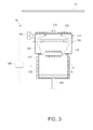
- Fig. 3 is a view showing that a source material is transferred in a direction of getting away from a first heater in the depositing apparatus of Fig. 2 for forming a thin film.
- the depositing apparatus for forming a thin film in this exemplary embodiment which is an apparatus capable of evaporating an organic substance and depositing it in the form of a thin film on a substrate, includes a source container 110, a cooler 120, an evaporation chamber 130, a spraying hole 140, a first heater 150, a block plate 160, a second heater 170, a transfer unit 180, a sensor 190 and a controller 192.
- the present invention provides an apparatus for manufacturing an organic light emitting device (OLED), in which a source material used in exemplary embodiments may be an organic substance by way of an example.
- OLED organic light emitting device
- the source container 110 in which the source material 1 to be deposited on the substrate 10 is accommodated in a solid or liquid state, is shaped like a cylinder opened at one side.
- the source container 110 is made of a tungsten material, and filled with the organic substance as the source material 1 to be deposited on the substrate 10.
- the source container 110 may connect with a vacuum line (not shown) for keeping the inside of the source container 110 under a vacuum pressure condition while performing a deposition process.
- the source material 1 is denaturalized under high temperature and pressure in the source container 110.
- the temperature and pressure in the source container 110 has to be kept low.
- the evaporation point of the source material 1 is much affected by the degree of a vacuum. Since the evaporation point is tend to lower as the degree of a vacuum decreases, the degree of a vacuum kept low in the source container 110 is more efficient in preventing the source material from denaturalization.
- the cooler 120 cools the source material 1 accommodated in the source container 110 in order to prevent the source material 1 accommodated in the source material 110 from being denaturalized by heat from the first heater 150 (to be described later).
- the cooler 120 is configured to surround an outer wall of the source container 110.
- the cooler 120 may be achieved by in various forms capable of cooling the inside of the source container 110 filled with the source material 1.
- a cooling jacket is used for example.
- the cooler 120 is configured by surrounding the outer circumference of the source container 110 with a cooling channel in which a coolant flows.
- the evaporation chamber 130 which provides a space through which the evaporated source material 1 from the source container 110 passes, is coupled to and communicates with the source container 110 at an upper side of the source container 110.
- the source material 1 accommodated in the source container 110 as the solid or liquid state is heated by the first heater 150 to be described later, and the heated source material 1 gasified and vaporized upward.
- the evaporated source material 1 is introduced into the evaporation chamber 130 arranged above the source container 110, and then passes through the evaporation chamber 130, so that the evaporated material 1 can be sprayed toward the substrate 10 via the spraying hole 140 (to be described later).
- the evaporation chamber 130 has a volume large enough to accommodate a considerable amount of evaporated source material 1. As the source material 1 evaporated from the source container 110 is sufficiently accommodated in the evaporation chamber 130, the amount of source material sprayed toward the substrate 10 via the spraying hole 140 can be stably maintained.
- the evaporation chamber 130 is formed to have a sufficient inner space, and thus serves as a kind of accumulator.
- the evaporation chamber 130 is detachably coupled to the source container 110.
- the source material 1 i.e., the organic substance to be deposited on the substrate 10
- the deposition process is suspended and the source container 110 is separated from the evaporation chamber 130. Thereafter, if the source material 1 is completely filled in the source container 110, the source container 110 is coupled again to the evaporation chamber 130 and the deposition process is resumed.
- a plurality of source containers 110 are respectively provided to correspond to a plurality of organic substances, and the source container 110 accommodating the organic substance to be used in each deposition process is selected and mounted to the evaporation chamber 130.
- the spraying hole 140 which is an opening for spraying the evaporated source material 1 passed through the evaporation chamber 130 upward, i.e., toward the substrate 10, is formed on the top of the evaporation chamber.
- the spraying hole 140 is aligned in a breadth direction of the substrate 10 and faces the substrate 10.
- the spraying hole 140 may be manufactured as a separate part in the form of a nozzle and coupled to the evaporation chamber 130, and may be integrally formed as a through hole on an upper wall of the evaporation chamber 130.
- the first heater 150 which supplies heat to the source material 1 so as to evaporate the source material 1 accommodated in the source container 110, is installed inside the evaporation chamber 130 or above the source material 1 inside the source container 110.
- the first heater 150 may have various shapes as long as it can supply thermal energy for evaporating the source material 1.
- a core heater, a lamp heater or the like may be employed.
- the core heater is used as the first heater 150.
- the first heater 150 is achieved by winding a resistive hot wire around a plate inside the evaporation chamber 130. At this time, the resistive hot wire may contain Ta, W, Mo or alloy thereof.
- the heater for supplying heat to the source material accommodated in the source container is generally installed in an outer wall of the source container.
- the first heater 150 is installed in the same space as that for the source material 1, so that the heat from the first heater 150 can be directly transferred to the source material 1 without a medium. Accordingly, a temperature reaction of the source material 1 can be quickly achieved by temperature control of the first heater 150, and a desired target temperature for the source material 1 can be constantly maintained without large variation.
- the block plate 160 prevents that the source material 1 accommodated in the source container 110 or foreign materials are sputtered and attached to the spraying holes 140 while the first heater 150 supplies heat to the source container 1.
- the gasified source material 1 is normally vaporized from the surface of the liquid source material 1.
- the liquid source material may be suddenly splashed or the foreign materials mixed in the source material 1 may be suddenly spattered.
- the block plate 160 blocks the source material 1 or foreign materials that are not evaporated but sputtered and attached to the spraying hole 140, and makes continuous production possible for a long time, thereby increasing the yield of the apparatus.
- heat from a top of the block plate may be transferred to the source material 1 through a communicated path.
- the amount of evaporating the source material 1 control of which is based on a distance between the first heater 150 and the source material 1 or the temperature of the first heater 150, may be varied depending on an unexpected external factor. Change in the amount of evaporating the source material 1 directly affects the thickness of an organic light emitting diode, and causes a defective product.
- the block plate 160 is used to fully intercept heat being transferred from the outside to the source material 1, thereby eliminating the external factors that may affect the amount of evaporating the source material 1.
- the block plate 160 is shaped like a flat plate and installed inside the evaporation chamber 130, and arranged above the first heater 150. Also, the block plate 160 is spaced apart at a predetermined distance from an inner wall of the evaporation chamber 130, so that the evaporated source material can pass through a space between the block plate 160 and the inner wall of the evaporation chamber 130 and move toward the spraying hole 140.
- the second heater 170 which supplies heat to the evaporation chamber 130 in order to prevent the evaporated source material 1 passing through the evaporation chamber 130 from phase change into the liquid or solid state, is installed on the top and lateral sides of the evaporation chamber 130.
- the second heater 170 may employ the core heater, the lamp heater, or the like, and the resistive hot wire used at this time may contain Ta, W, Mo or alloy thereof.
- the second heater 170 prevents a phenomenon that the evaporated source material 1 is not deposited on the substrate 10 but attached to and clogging the spraying hole 140.
- the evaporated source material 1 remained in the evaporation chamber is accumulated at a side of the spraying hole 140 and thus results in clogging the spraying hole 140 through the phase change into the solid state. Therefore, the second heater 170 increases the temperature around the spraying hole 140 so that the source material around the spraying hole 140 can be always maintained in a gasified state.
- the transfer unit 180 reciprocates the source material 1 in a direction of getting close to the first heater 150 or getting away from the first heater 150.
- the transfer unit 180 is used to adjust the distance between the source material 1 and the first heater 150, thereby controlling the amount of source material 1 to be evaporated.
- the source material 1 is transferred in the direction of getting close to the first heater 150 so that sufficient heat can be supplied from the first heater 150 to the source material 1, thereby increasing the evaporation amount of source material 1.
- the evaporation amount of source material 1 is more than a preset reference amount, the source material 1 is transferred in the direction of getting away from the first heater 150 so that heat supplied from the first heater 150 to the source material 1 can be decreased, thereby decreasing the evaporation amount of source material 1.
- the transfer unit 180 may be configured in various forms as long as it can have a linear reciprocation motion.
- a pneumatic cylinder, a linear motor, combination of a rotary motor and a ball screw, and the like configuration well-known to those skilled in the art may be employed, and thus detailed descriptions thereof will be omitted.
- the sensor 190 is installed in the evaporation chamber 130, and senses the amount of evaporated source material 1 passing through the evaporation chamber 130. In accordance with the amount of the evaporated source material 1 sensed by the sensor 190, the temperature of the first heater 150 and an operating direction or transferring speed of the transfer unit 180 are controlled to thereby adjust the amount of evaporated source material 1.
- the controller 192 gets feedback on the amount of evaporated source material 1 from the sensor 190 and controls the first heater 150 or the transfer unit 180.
- the controller 192 transmits a signal to the transfer unit 180 so that the source material 1 can be transferred in the direction of getting close to the first heater 150, or transmits a signal for increasing the temperature of the first heater 150, thereby increasing the evaporation amount of source material 1.
- the controller 192 transmits a signal to the transfer unit 180 so that the source material 1 can be transferred in the direction of getting away from the first heater 150, or transmits a signal for decreasing the temperature of the first heater 150, thereby decreasing the evaporation amount of source material 1.
- the depositing apparatus for forming a thin film prevents a source material sputtered up from the source container or foreign materials from being attached to the spraying hole, and makes continuous production possible for a long time without suspending the production.
- the depositing apparatus for forming a thin film the heat is directly transferred from the first heater to the source material without a medium, so that a temperature reaction of the source material can be quickly achieved by temperature control of the first heater; a desired target temperature for the source material can be constantly maintained without large variation; and the source material can be stably evaporated to thereby achieve uniform deposition and large area deposition.
- the depositing apparatus for forming a thin film includes the second heater installed in the top and lateral sides of the evaporation chamber and supplying heat to the evaporation chamber, so that the evaporated source material passing through the evaporation chamber can be prevented from phase change into a liquid or solid state, and the evaporated source material remained without being deposited on the substrate can be prevented from being attached to and clogging up the spraying hole.
- the amount of source material evaporated from the source container is controlled by adjusting a distance between the source material and the first heater or the temperature of the first heater, thereby stably maintaining the amount of evaporated source material.
- Fig. 4 is a schematic view showing an alternative example of the depositing apparatus of Fig. 2 for forming a thin film.
- a depositing apparatus 100' for forming a thin film includes an additional crucible 111 inside the source container 110.
- a separate crucible is provided for accommodating the source material, thereby preventing the source material from leaking and contaminating the transfer unit.
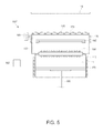
- Fig. 5 is a schematic view showing another alternative example of the depositing apparatus of Fig. 2 for forming a thin film.
- a depositing apparatus 100" for forming a thin film includes a plurality of spraying holes 140, thereby stably and uniformly deposition the source material on a large-area substrate 10.
- elements have the same configuration and functions as those of elements referred to by the same numerals shown in Figs. 2 and 3 , and thus detailed descriptions thereof will be omitted.
Landscapes
- Chemical & Material Sciences (AREA)
- Engineering & Computer Science (AREA)
- Chemical Kinetics & Catalysis (AREA)
- Materials Engineering (AREA)
- Mechanical Engineering (AREA)
- Metallurgy (AREA)
- Organic Chemistry (AREA)
- Manufacturing & Machinery (AREA)
- Physical Vapour Deposition (AREA)
- Electroluminescent Light Sources (AREA)
Abstract
Description
- This application claims priority to and the benefit of Korean Patent Application No.
10-2011-0034338 - The present invention relates to a depositing apparatus for forming a thin film, and more particularly to a depositing apparatus for forming a thin film, in which an organic substance can be evaporated and deposited on a substrate in the form of a thin film.
- An organic light emitting device is a next-generation display device that can emit light in itself, which is excellent in a viewing angle, contrast, response speed, power consumption, etc. as compared with those of a liquid crystal display (LCD) device.
- The organic light emitting device includes organic light emitting diodes connected between scan lines and data lines as a matrix type and forming pixels. The organic light emitting diode includes an anode, a cathode, and an organic thin film layer formed between the anode and the cathode and having a hole transport layer, an organ light emitting layer and an electron transport layer. When a predetermined voltage is applied between the anode and the cathode, holes injected from the anode and electrons injected from the cathode are recombined in the light emitting layer, while emitting light based on energy difference.
- An organic substance, used in a deposition process for the organic thin film layer to manufacture the organic light emitting device, does not require a high vapor pressure and is easily broken-down and denatured at high temperature on the contrary to an inorganic substance. Due to such material properties, a source container made of a tungsten material is filled with an organic substance and heated to evaporate the organic substance, thereby depositing a conventional organic thin film on a substrate.
-
Fig. 1 shows an example of a conventional depositing apparatus for forming a thin film. - Referring to
Fig. 1 , the conventional depositing apparatus for forming a thin film is configured to deposit a source material to asubstrate 10 supported in a vertically direction. Further, the conventional depositing apparatus includes asource container 20 shaped like a cylindrical pipe and internally divided into astorage space 21 at a lower side to be filled with a source material and anevaporation space 22 at an upper side where the source material is evaporated; aheater 30 for heating the source material in thesource container 20; and a cooler 40 for cooling the source material so that the source material filled in thestorage space 21 can be prevent from denaturalization. - Also, the conventional depositing apparatus for forming a thin film includes a
cylinder head 51 for lifting up the source material; atransfer unit 50 for transferring thecylinder head 51; aconnection pipe 60 for guiding the evaporated source material to aninjector 70; and aspraying hole 71 for spraying the evaporated source material in a horizontal direction. - However, the amount of deposition sources, which the source container is capable of storing, is limited, and therefore there arises problems in that the source material for the deposition has to be frequently refilled and on all such occasions the depositing apparatus for forming a thin film should be shut down.
- Meanwhile, a method of injecting the source material upward has been proposed, but it has problems that the source material is attached to and clogs the spraying hole, and thus the source material is not sprayed toward the substrate, thereby causing defective products. In this case, the spraying hole on which the source material is accumulated has to be replaced with a new one or cleaned while production is suspended, and then the production can be resumed. Accordingly, there is an inevitable problem that a decrease in production is caused by the suspended production.
- Also, if the evaporated materials are accumulated on the spraying hole or internal parts or operating units, it may not only have an effect on the performance of the parts and units but also damage the parts and units in severe cases. Particularly, the more the source material is used, the more such phenomenon becomes severe.
- Accordingly, the present invention is conceived to solve the forgoing problems, and an aspect of the present invention is to provide a depositing apparatus for forming a thin film, in which a block plate for preventing a source material sputtered from a source container or foreign materials from being attached to a spraying hole is provided inside an evaporation chamber so that the source material can be stably and continuously evaporated; the source material is stably evaporated through direct temperature control to make uniform deposition and large area deposition be possible; and continuous production is possible for a long time without suspending the production.
- In accordance with an exemplary embodiment of the present invention, there is provided a depositing apparatus for forming a thin film, the apparatus including a source container in which a source material to be deposited on a substrate is accommodated in a solid or liquid state; an evaporation chamber which couples and communicates with the source container above the source container, and through which an evaporated source material from the source container passes; a spraying hole which is formed on a top of the evaporation chamber, and sprays upward the evaporated source material passed through the evaporation chamber; a first heater which is provided above the source material inside the evaporation chamber or the source container, and supplies heat to the source material to evaporate the source material accommodated in the source container; and a block plate which is provided above the first heater inside the evaporation chamber, and prevents the source material or foreign materials contained in the source container from being sputtered and attached to the spraying hole while the first heater supplies heat to the source material.
- The block plate may be shaped like a flat plate, and spaced apart at a predetermined distance from an inner wall of the evaporation chamber.
- The apparatus may further include a second heater provided on the top or lateral sides of the evaporation chamber, and supply heat to the evaporation chamber to prevent the evaporated source material passing through the evaporation chamber from phase change into a liquid or solid state.
- The source container may be detachably coupled to the evaporation chamber.
- The apparatus may further include a transfer unit for transferring the source material in a direction of getting close to the first heater or getting away from the first heater.
- The apparatus may further include a sensor provided in the evaporation chamber and sensing the amount of evaporated source material passing through the evaporation chamber.
- The apparatus may further include a transfer unit which transfers the source material in a direction of getting close to the first heater or getting away from the first heater; a sensor which is provided in the evaporation chamber and senses the amount of evaporated source material passing through the evaporation chamber; and a controller which gets feedback on the amount of evaporated source material from the sensor, and if the amount of evaporated source material is less than a preset reference amount, transmits a signal to the transfer unit so that the source material can be transferred in a direction of getting close to the first heater or transmits a signal for increasing temperature of the first heater, and if the amount of evaporated source material is more than the preset reference amount, transmits a signal to the transfer unit so that the source material can be transferred in a direction of getting away from the first heater or transmitting a signal for decreasing temperature of the first heater.
- As described above, the depositing apparatus for forming a thin film according to an exemplary embodiment of the present invention prevents a source material sputtered up from the source container or foreign materials from being attached to the spraying hole, and makes continuous production possible for a long time without suspending the production.
- Also, in the depositing apparatus for forming a thin film according to an exemplary embodiment of the present invention, a temperature reaction of the source material in the source container can be quickly achieved by temperature control of the first heater; a desired target temperature for the source material in the source container can be constantly maintained without large variation; and the source material can be stably evaporated to thereby achieve uniform deposition and large area deposition.
- Further, the depositing apparatus for forming a thin film according to an exemplary embodiment of the present invention can prevent the evaporated source material passing through the evaporation chamber from phase change into a liquid or solid state, and prevent the evaporated source material remained without being deposited on the substrate from being attached to and clogging up the spraying hole.
- Additionally, in the depositing apparatus for forming a thin film according to an exemplary embodiment of the present invention, the amount of source material evaporated from the source container is controlled by adjusting a distance between the source material and the first heater or the temperature of the first heater, thereby stably maintaining the amount of evaporated source material.
- The above and/or other aspects of the present invention will become apparent and more readily appreciated from the following description of the exemplary embodiments, taken in conjunction with the accompanying drawings, in which:
-
Fig. 1 shows an example of a conventional depositing apparatus for forming a thin film; -
Fig. 2 is a schematic view of a depositing apparatus for forming a thin film according to an exemplary embodiment of the present invention; -
Fig. 3 is a view showing that a source material is transferred in a direction of getting away from a first heater in the depositing apparatus ofFig. 2 for forming a thin film; -
Fig. 4 is a schematic view showing an alternative example of the depositing apparatus ofFig. 2 for forming a thin film; and -
Fig. 5 is a schematic view showing another alternative example of the depositing apparatus ofFig. 2 for forming a thin film. - Hereinafter, exemplary embodiments of a depositing apparatus for forming a thin film according to the present invention will be described with reference to accompanying drawings.
-
Fig. 2 is a schematic view of a depositing apparatus for forming a thin film according to an exemplary embodiment, andFig. 3 is a view showing that a source material is transferred in a direction of getting away from a first heater in the depositing apparatus ofFig. 2 for forming a thin film. - Referring to
Figs. 2 and3 , the depositing apparatus for forming a thin film in this exemplary embodiment, which is an apparatus capable of evaporating an organic substance and depositing it in the form of a thin film on a substrate, includes asource container 110, acooler 120, anevaporation chamber 130, aspraying hole 140, afirst heater 150, ablock plate 160, asecond heater 170, atransfer unit 180, asensor 190 and acontroller 192. - The present invention provides an apparatus for manufacturing an organic light emitting device (OLED), in which a source material used in exemplary embodiments may be an organic substance by way of an example.
- The
source container 110, in which thesource material 1 to be deposited on thesubstrate 10 is accommodated in a solid or liquid state, is shaped like a cylinder opened at one side. Generally, thesource container 110 is made of a tungsten material, and filled with the organic substance as thesource material 1 to be deposited on thesubstrate 10. - At this time, the
source container 110 may connect with a vacuum line (not shown) for keeping the inside of thesource container 110 under a vacuum pressure condition while performing a deposition process. Thesource material 1 is denaturalized under high temperature and pressure in thesource container 110. To prevent thesource material 1 from the denaturalization, the temperature and pressure in thesource container 110 has to be kept low. Also, the evaporation point of thesource material 1 is much affected by the degree of a vacuum. Since the evaporation point is tend to lower as the degree of a vacuum decreases, the degree of a vacuum kept low in thesource container 110 is more efficient in preventing the source material from denaturalization. - The
cooler 120 cools thesource material 1 accommodated in thesource container 110 in order to prevent thesource material 1 accommodated in thesource material 110 from being denaturalized by heat from the first heater 150 (to be described later). Thecooler 120 is configured to surround an outer wall of thesource container 110. - The
cooler 120 may be achieved by in various forms capable of cooling the inside of thesource container 110 filled with thesource material 1. In this exemplary embodiment, a cooling jacket is used for example. Thecooler 120 is configured by surrounding the outer circumference of thesource container 110 with a cooling channel in which a coolant flows. - The
evaporation chamber 130, which provides a space through which the evaporatedsource material 1 from thesource container 110 passes, is coupled to and communicates with thesource container 110 at an upper side of thesource container 110. Thesource material 1 accommodated in thesource container 110 as the solid or liquid state is heated by thefirst heater 150 to be described later, and the heatedsource material 1 gasified and vaporized upward. The evaporatedsource material 1 is introduced into theevaporation chamber 130 arranged above thesource container 110, and then passes through theevaporation chamber 130, so that the evaporatedmaterial 1 can be sprayed toward thesubstrate 10 via the spraying hole 140 (to be described later). - The
evaporation chamber 130 has a volume large enough to accommodate a considerable amount of evaporatedsource material 1. As thesource material 1 evaporated from thesource container 110 is sufficiently accommodated in theevaporation chamber 130, the amount of source material sprayed toward thesubstrate 10 via thespraying hole 140 can be stably maintained. Theevaporation chamber 130 is formed to have a sufficient inner space, and thus serves as a kind of accumulator. - The
evaporation chamber 130 is detachably coupled to thesource container 110. When thesource material 1, i.e., the organic substance to be deposited on thesubstrate 10 is filled in thesource container 110, the deposition process is suspended and thesource container 110 is separated from theevaporation chamber 130. Thereafter, if thesource material 1 is completely filled in thesource container 110, thesource container 110 is coupled again to theevaporation chamber 130 and the deposition process is resumed. - In the case where various kinds of organic thin films are sequentially stacked, a plurality of
source containers 110 are respectively provided to correspond to a plurality of organic substances, and thesource container 110 accommodating the organic substance to be used in each deposition process is selected and mounted to theevaporation chamber 130. - The spraying
hole 140, which is an opening for spraying the evaporatedsource material 1 passed through theevaporation chamber 130 upward, i.e., toward thesubstrate 10, is formed on the top of the evaporation chamber. The sprayinghole 140 is aligned in a breadth direction of thesubstrate 10 and faces thesubstrate 10. - The spraying
hole 140 may be manufactured as a separate part in the form of a nozzle and coupled to theevaporation chamber 130, and may be integrally formed as a through hole on an upper wall of theevaporation chamber 130. - The
first heater 150, which supplies heat to thesource material 1 so as to evaporate thesource material 1 accommodated in thesource container 110, is installed inside theevaporation chamber 130 or above thesource material 1 inside thesource container 110. - The
first heater 150 may have various shapes as long as it can supply thermal energy for evaporating thesource material 1. For instance, a core heater, a lamp heater or the like may be employed. In this exemplary embodiment, the core heater is used as thefirst heater 150. Thefirst heater 150 is achieved by winding a resistive hot wire around a plate inside theevaporation chamber 130. At this time, the resistive hot wire may contain Ta, W, Mo or alloy thereof. - Conventionally, the heater for supplying heat to the source material accommodated in the source container is generally installed in an outer wall of the source container. However, in this exemplary embodiment, the
first heater 150 is installed in the same space as that for thesource material 1, so that the heat from thefirst heater 150 can be directly transferred to thesource material 1 without a medium. Accordingly, a temperature reaction of thesource material 1 can be quickly achieved by temperature control of thefirst heater 150, and a desired target temperature for thesource material 1 can be constantly maintained without large variation. - The
block plate 160 prevents that thesource material 1 accommodated in thesource container 110 or foreign materials are sputtered and attached to the spraying holes 140 while thefirst heater 150 supplies heat to thesource container 1. - While the
source material 1 is heated by thefirst heater 150, thegasified source material 1 is normally vaporized from the surface of theliquid source material 1. However, the liquid source material may be suddenly splashed or the foreign materials mixed in thesource material 1 may be suddenly spattered. - As the sputtered
source material 1 or foreign materials are attached to thespraying hole 140, there arises a problem of clogging thespraying hole 140. If thespraying hole 140 is clogged, the process has to be suspended for replacing it with a new one or cleaning thespraying hole 140 and then resumed. In this case, a yield of the apparatus is decreased. - Thus, the
block plate 160 blocks thesource material 1 or foreign materials that are not evaporated but sputtered and attached to thespraying hole 140, and makes continuous production possible for a long time, thereby increasing the yield of the apparatus. - Meanwhile, heat from a top of the block plate may be transferred to the
source material 1 through a communicated path. In this case, the amount of evaporating thesource material 1, control of which is based on a distance between thefirst heater 150 and thesource material 1 or the temperature of thefirst heater 150, may be varied depending on an unexpected external factor. Change in the amount of evaporating thesource material 1 directly affects the thickness of an organic light emitting diode, and causes a defective product. - Therefore, the
block plate 160 is used to fully intercept heat being transferred from the outside to thesource material 1, thereby eliminating the external factors that may affect the amount of evaporating thesource material 1. - The
block plate 160 is shaped like a flat plate and installed inside theevaporation chamber 130, and arranged above thefirst heater 150. Also, theblock plate 160 is spaced apart at a predetermined distance from an inner wall of theevaporation chamber 130, so that the evaporated source material can pass through a space between theblock plate 160 and the inner wall of theevaporation chamber 130 and move toward thespraying hole 140. - The
second heater 170, which supplies heat to theevaporation chamber 130 in order to prevent the evaporatedsource material 1 passing through theevaporation chamber 130 from phase change into the liquid or solid state, is installed on the top and lateral sides of theevaporation chamber 130. - Likewise, the
second heater 170 may employ the core heater, the lamp heater, or the like, and the resistive hot wire used at this time may contain Ta, W, Mo or alloy thereof. - The
second heater 170 prevents a phenomenon that the evaporatedsource material 1 is not deposited on thesubstrate 10 but attached to and clogging thespraying hole 140. The evaporatedsource material 1 remained in the evaporation chamber is accumulated at a side of thespraying hole 140 and thus results in clogging thespraying hole 140 through the phase change into the solid state. Therefore, thesecond heater 170 increases the temperature around thespraying hole 140 so that the source material around thespraying hole 140 can be always maintained in a gasified state. - The
transfer unit 180 reciprocates thesource material 1 in a direction of getting close to thefirst heater 150 or getting away from thefirst heater 150. Thetransfer unit 180 is used to adjust the distance between thesource material 1 and thefirst heater 150, thereby controlling the amount ofsource material 1 to be evaporated. - For example, if the evaporation amount of
source material 1 is less than a preset reference amount, thesource material 1 is transferred in the direction of getting close to thefirst heater 150 so that sufficient heat can be supplied from thefirst heater 150 to thesource material 1, thereby increasing the evaporation amount ofsource material 1. On the other hand, if the evaporation amount ofsource material 1 is more than a preset reference amount, thesource material 1 is transferred in the direction of getting away from thefirst heater 150 so that heat supplied from thefirst heater 150 to thesource material 1 can be decreased, thereby decreasing the evaporation amount ofsource material 1. - The
transfer unit 180 may be configured in various forms as long as it can have a linear reciprocation motion. For example, a pneumatic cylinder, a linear motor, combination of a rotary motor and a ball screw, and the like configuration well-known to those skilled in the art may be employed, and thus detailed descriptions thereof will be omitted. - The
sensor 190 is installed in theevaporation chamber 130, and senses the amount of evaporatedsource material 1 passing through theevaporation chamber 130. In accordance with the amount of the evaporatedsource material 1 sensed by thesensor 190, the temperature of thefirst heater 150 and an operating direction or transferring speed of thetransfer unit 180 are controlled to thereby adjust the amount of evaporatedsource material 1. - The
controller 192 gets feedback on the amount of evaporatedsource material 1 from thesensor 190 and controls thefirst heater 150 or thetransfer unit 180. - For example, if the evaporation amount of
source material 1 is less than the reference amount, thecontroller 192 transmits a signal to thetransfer unit 180 so that thesource material 1 can be transferred in the direction of getting close to thefirst heater 150, or transmits a signal for increasing the temperature of thefirst heater 150, thereby increasing the evaporation amount ofsource material 1. - On the other hand, if the evaporation amount of
source material 1 is more than the reference amount, thecontroller 192 transmits a signal to thetransfer unit 180 so that thesource material 1 can be transferred in the direction of getting away from thefirst heater 150, or transmits a signal for decreasing the temperature of thefirst heater 150, thereby decreasing the evaporation amount ofsource material 1. - As described above, the depositing apparatus for forming a thin film according to an exemplary embodiment of the present invention prevents a source material sputtered up from the source container or foreign materials from being attached to the spraying hole, and makes continuous production possible for a long time without suspending the production.
- Also, the depositing apparatus for forming a thin film according to an exemplary embodiment of the present invention, the heat is directly transferred from the first heater to the source material without a medium, so that a temperature reaction of the source material can be quickly achieved by temperature control of the first heater; a desired target temperature for the source material can be constantly maintained without large variation; and the source material can be stably evaporated to thereby achieve uniform deposition and large area deposition.
- Further, the depositing apparatus for forming a thin film according to an exemplary embodiment of the present invention includes the second heater installed in the top and lateral sides of the evaporation chamber and supplying heat to the evaporation chamber, so that the evaporated source material passing through the evaporation chamber can be prevented from phase change into a liquid or solid state, and the evaporated source material remained without being deposited on the substrate can be prevented from being attached to and clogging up the spraying hole.
- Additionally, in the depositing apparatus for forming a thin film according to an exemplary embodiment of the present invention, the amount of source material evaporated from the source container is controlled by adjusting a distance between the source material and the first heater or the temperature of the first heater, thereby stably maintaining the amount of evaporated source material.
-
Fig. 4 is a schematic view showing an alternative example of the depositing apparatus ofFig. 2 for forming a thin film. - Referring to
Fig. 4 , a depositing apparatus 100' for forming a thin film includes anadditional crucible 111 inside thesource container 110. In the case of a liquid source material, it may leak downward while being transferred by the transfer unit. Accordingly, a separate crucible is provided for accommodating the source material, thereby preventing the source material from leaking and contaminating the transfer unit. - In
Fig. 4 , elements have the same configuration and functions as those of elements referred to by the same numerals shown inFigs. 2 and3 , and thus detailed descriptions thereof will be omitted. -
Fig. 5 is a schematic view showing another alternative example of the depositing apparatus ofFig. 2 for forming a thin film. - Referring to
Fig. 5 , adepositing apparatus 100" for forming a thin film includes a plurality of sprayingholes 140, thereby stably and uniformly deposition the source material on a large-area substrate 10. InFig. 5 , elements have the same configuration and functions as those of elements referred to by the same numerals shown inFigs. 2 and3 , and thus detailed descriptions thereof will be omitted. - Although a few exemplary embodiments of the present invention have been shown and described, it will be appreciated by those skilled in the art that changes may be made in these embodiments without departing from the principles and spirit of the invention, the scope of which is defined in the appended claims and their equivalents.
Claims (7)
- A depositing apparatus (100) for forming a thin film, the apparatus comprising
a source container (110) in which a source material (1) to be deposited on a substrate (10) is accommodated in a solid or liquid state;
an evaporation chamber (130) which couples and communicates with the source container (110) above the source container (110), and through which an evaporated source material from the source container (110) passes;
a spraying hole (140) which is formed on a top of the evaporation chamber (130), and sprays upward the evaporated source material passed through the evaporation chamber (130);
a first heater (150) which is provided above the source material (1) inside the evaporation chamber (130) or the source container (110), and supplies heat to the source material (1) to evaporate the source material (1) accommodated in the source container (110); and
a block plate (160) which is provided above the first heater (150) inside the evaporation chamber (130), and prevents the source material (1) or foreign materials contained in the source container (110) from being sputtered and attached to the spraying hole (140) while the first heater (150) supplies heat to the source material (1). - The apparatus according to claim 1, wherein the block plate (160) is shaped like a flat plate, and spaced apart at a predetermined distance from an inner wall of the evaporation chamber (130).
- The apparatus according to claim 1, further comprising a second heater (170) provided on the top or lateral sides of the evaporation chamber (130), and supplying heat to the evaporation chamber (130) to prevent the evaporated source material passing through the evaporation chamber (130) from phase change into a liquid or solid state.
- The apparatus according to claim 1, wherein the source container (110) is detachably coupled to the evaporation chamber (130).
- The apparatus according to claim 1, further comprising a transfer unit (180) for transferring the source material (1) in a direction of getting close to the first heater (150) or getting away from the first heater (150).
- The apparatus according to claim 1, further comprising a sensor (190) provided in the evaporation chamber (130) and sensing the amount of evaporated source material passing through the evaporation chamber (130).
- The apparatus according to claim 1, further comprising:a transfer unit (180) which transfers the source material (1) in a direction of getting close to the first heater (150) or getting away from the first heater (150);a sensor (190) which is provided in the evaporation chamber (130) and senses the amount of evaporated source material passing through the evaporation chamber (130); anda controller (192) which gets feedback on the amount of evaporated source material from the sensor (190), and if the amount of evaporated source material is less than a preset reference amount, transmits a signal to the transfer unit (180) so that the source material (1) can be transferred in a direction of getting close to the first heater (150) or transmits a signal for increasing temperature of the first heater (150), and if the amount of evaporated source material is more than the preset reference amount, transmits a signal to the transfer unit (180) so that the source material (1) can be transferred in a direction of getting away from the first heater (150) or transmitting a signal for decreasing temperature of the first heater (150).
Applications Claiming Priority (1)
| Application Number | Priority Date | Filing Date | Title |
|---|---|---|---|
| KR1020110034338A KR101052435B1 (en) | 2011-04-13 | 2011-04-13 | Thin film deposition equipment |
Publications (2)
| Publication Number | Publication Date |
|---|---|
| EP2511395A2 true EP2511395A2 (en) | 2012-10-17 |
| EP2511395A3 EP2511395A3 (en) | 2015-02-18 |
Family
ID=44924172
Family Applications (1)
| Application Number | Title | Priority Date | Filing Date |
|---|---|---|---|
| EP12163927.2A Withdrawn EP2511395A3 (en) | 2011-04-13 | 2012-04-12 | Depositing apparatus for forming thin film |
Country Status (6)
| Country | Link |
|---|---|
| US (1) | US20120260855A1 (en) |
| EP (1) | EP2511395A3 (en) |
| JP (1) | JP2012219376A (en) |
| KR (1) | KR101052435B1 (en) |
| CN (1) | CN102732842A (en) |
| TW (1) | TWI493062B (en) |
Families Citing this family (8)
| Publication number | Priority date | Publication date | Assignee | Title |
|---|---|---|---|---|
| CN103608484B (en) * | 2011-04-20 | 2016-06-22 | Oled工厂有限责任公司 | Measurement device and method for vapour deposition application |
| US8778081B2 (en) | 2012-01-04 | 2014-07-15 | Colorado State University Research Foundation | Process and hardware for deposition of complex thin-film alloys over large areas |
| KR101418714B1 (en) * | 2012-09-13 | 2014-07-10 | 주식회사 선익시스템 | Evaporation source and Apparatus for deposition having the same |
| CN103695848B (en) * | 2013-12-30 | 2015-10-14 | 京东方科技集团股份有限公司 | Evaporated device and evaporation coating method thereof |
| EP3184666B1 (en) * | 2015-12-23 | 2018-06-13 | Singulus Technologies AG | System and method for gas phase deposition |
| JP6469936B1 (en) * | 2017-03-16 | 2019-02-13 | 堺ディスプレイプロダクト株式会社 | Organic EL device manufacturing method, film forming method, and film forming apparatus |
| CN107723663B (en) * | 2017-09-26 | 2019-11-12 | 常州大学 | A device and method for continuous vacuum evaporation metal antimony on the surface of high-strength steel |
| KR102547617B1 (en) * | 2022-06-23 | 2023-06-26 | 큐알티 주식회사 | Semiconductor device test apparatus that provides an accelerated environment and method for testing semiconductor devices in an accelerated environment using the same |
Family Cites Families (18)
| Publication number | Priority date | Publication date | Assignee | Title |
|---|---|---|---|---|
| US4551303A (en) * | 1982-09-04 | 1985-11-05 | Konishiroku Photo Industry Co., Ltd. | Method of using an evaporation source |
| US20050147753A1 (en) * | 1999-10-22 | 2005-07-07 | Kurt J. Lesker Company | Material deposition system and a method for coating a substrate or thermally processing a material in a vacuum |
| JP3712646B2 (en) * | 2001-08-03 | 2005-11-02 | 株式会社エイコー・エンジニアリング | Molecular beam cell for thin film deposition |
| JP2003193217A (en) * | 2001-12-25 | 2003-07-09 | Nippon Seiki Co Ltd | Vapor deposition apparatus |
| US20030168013A1 (en) * | 2002-03-08 | 2003-09-11 | Eastman Kodak Company | Elongated thermal physical vapor deposition source with plural apertures for making an organic light-emitting device |
| US20040000379A1 (en) * | 2002-06-27 | 2004-01-01 | Ulvac, Inc. | Evaporation container and evaporation source |
| DE60305246T2 (en) * | 2002-07-19 | 2006-09-14 | Lg Electronics Inc. | Thermal PVD coating source for organic electroluminescent layers |
| KR100490537B1 (en) * | 2002-07-23 | 2005-05-17 | 삼성에스디아이 주식회사 | Heating crucible and deposit apparatus utilizing the same |
| US20040144321A1 (en) * | 2003-01-28 | 2004-07-29 | Eastman Kodak Company | Method of designing a thermal physical vapor deposition system |
| US7339139B2 (en) * | 2003-10-03 | 2008-03-04 | Darly Custom Technology, Inc. | Multi-layered radiant thermal evaporator and method of use |
| JP2006059640A (en) * | 2004-08-19 | 2006-03-02 | Tdk Corp | Vapor deposition device and vapor deposition method |
| WO2006043723A1 (en) * | 2004-10-21 | 2006-04-27 | Futaba Corporation | Evaporation source |
| WO2006075401A1 (en) * | 2005-01-17 | 2006-07-20 | Youtec Co., Ltd. | Evaporation source and vapor deposition apparatus |
| WO2007069865A1 (en) * | 2005-12-16 | 2007-06-21 | Doosan Mecatec Co., Ltd. | Crucible assembly for deposition of organic thin film |
| KR100980729B1 (en) * | 2006-07-03 | 2010-09-07 | 주식회사 야스 | Multi-nozzle evaporation source for deposition process |
| KR100926437B1 (en) | 2008-11-17 | 2009-11-13 | 에스엔유 프리시젼 주식회사 | Evaporation material supply apparatus and substrate processing apparatus having the same |
| KR101015277B1 (en) * | 2008-12-10 | 2011-02-15 | 삼성모바일디스플레이주식회사 | Evaporation source |
| KR20110024223A (en) * | 2009-09-01 | 2011-03-09 | 주식회사 선익시스템 | Evaporation apparatus and vacuum deposition apparatus comprising the same |
-
2011
- 2011-04-13 KR KR1020110034338A patent/KR101052435B1/en not_active Expired - Fee Related
-
2012
- 2012-04-05 US US13/440,377 patent/US20120260855A1/en not_active Abandoned
- 2012-04-12 EP EP12163927.2A patent/EP2511395A3/en not_active Withdrawn
- 2012-04-12 JP JP2012090742A patent/JP2012219376A/en active Pending
- 2012-04-13 TW TW101113253A patent/TWI493062B/en not_active IP Right Cessation
- 2012-04-13 CN CN2012101203485A patent/CN102732842A/en active Pending
Non-Patent Citations (1)
| Title |
|---|
| None |
Also Published As
| Publication number | Publication date |
|---|---|
| EP2511395A3 (en) | 2015-02-18 |
| TWI493062B (en) | 2015-07-21 |
| JP2012219376A (en) | 2012-11-12 |
| KR101052435B1 (en) | 2011-07-28 |
| TW201247914A (en) | 2012-12-01 |
| US20120260855A1 (en) | 2012-10-18 |
| CN102732842A (en) | 2012-10-17 |
Similar Documents
| Publication | Publication Date | Title |
|---|---|---|
| US20120260855A1 (en) | Depositing apparatus for forming thin film | |
| KR101233629B1 (en) | Large capacity depositing apparatus for forming thin film | |
| KR100926437B1 (en) | Evaporation material supply apparatus and substrate processing apparatus having the same | |
| KR100823508B1 (en) | Evaporation source and deposition apparatus having same | |
| CN102414798B (en) | Raw material supply unit, thin film deposition device and method for depositing thin film | |
| KR101173645B1 (en) | Gas injection unit and apparatus for depositing thin film having the same | |
| KR101754356B1 (en) | Evaporating source, deposition material supply apparatus and deposition apparatus comprising the same | |
| JP2007186787A (en) | Evaporation crucible, thin film forming apparatus including the same, and display device manufacturing method | |
| JP2015067847A (en) | Vacuum deposition equipment | |
| KR20110062604A (en) | Source for Organic Thin Film Vacuum Thermal Deposition Equipment | |
| TWI438298B (en) | Apparatus for supplying materials | |
| JP5569756B2 (en) | Continuous thin film deposition equipment | |
| US20060251811A1 (en) | Controllably feeding powdered or granular material | |
| JP4673190B2 (en) | Molecular beam source for thin film deposition and its molecular dose control method | |
| KR101174633B1 (en) | Apparatus for supplying materials | |
| KR20150068153A (en) | Linear Type Eevaporator Having Plural Individual Crucibles | |
| KR100666571B1 (en) | Deposition apparatus using propeller type injection method | |
| KR100753145B1 (en) | Organic material deposition apparatus of organic light emitting device | |
| KR100795905B1 (en) | Apparatus for depositing organic film on substrate | |
| KR20150030970A (en) | Evaporation unit and Apparatus for deposition including the same | |
| JP2016098417A (en) | Vapor deposition apparatus and method for manufacturing organic el device | |
| KR20120126492A (en) | Apparatus for controlling supply of materials | |
| KR101633115B1 (en) | Source for depositing OLED | |
| KR20150061297A (en) | Evaporation source and evaporation apparatus having the same | |
| KR20080079787A (en) | Organic thin film deposition apparatus |
Legal Events
| Date | Code | Title | Description |
|---|---|---|---|
| PUAI | Public reference made under article 153(3) epc to a published international application that has entered the european phase |
Free format text: ORIGINAL CODE: 0009012 |
|
| AK | Designated contracting states |
Kind code of ref document: A2 Designated state(s): AL AT BE BG CH CY CZ DE DK EE ES FI FR GB GR HR HU IE IS IT LI LT LU LV MC MK MT NL NO PL PT RO RS SE SI SK SM TR |
|
| AX | Request for extension of the european patent |
Extension state: BA ME |
|
| PUAL | Search report despatched |
Free format text: ORIGINAL CODE: 0009013 |
|
| AK | Designated contracting states |
Kind code of ref document: A3 Designated state(s): AL AT BE BG CH CY CZ DE DK EE ES FI FR GB GR HR HU IE IS IT LI LT LU LV MC MK MT NL NO PL PT RO RS SE SI SK SM TR |
|
| AX | Request for extension of the european patent |
Extension state: BA ME |
|
| RIC1 | Information provided on ipc code assigned before grant |
Ipc: C23C 14/24 20060101ALI20150113BHEP Ipc: C23C 14/26 20060101ALI20150113BHEP Ipc: H05B 33/10 20060101ALI20150113BHEP Ipc: C23C 14/56 20060101ALI20150113BHEP Ipc: C23C 14/54 20060101ALI20150113BHEP Ipc: C23C 14/12 20060101AFI20150113BHEP |
|
| STAA | Information on the status of an ep patent application or granted ep patent |
Free format text: STATUS: THE APPLICATION IS DEEMED TO BE WITHDRAWN |
|
| 18D | Application deemed to be withdrawn |
Effective date: 20150819 |