EP2510568B1 - Flowing electrolyte reservoir system - Google Patents
Flowing electrolyte reservoir system Download PDFInfo
- Publication number
- EP2510568B1 EP2510568B1 EP10836850.7A EP10836850A EP2510568B1 EP 2510568 B1 EP2510568 B1 EP 2510568B1 EP 10836850 A EP10836850 A EP 10836850A EP 2510568 B1 EP2510568 B1 EP 2510568B1
- Authority
- EP
- European Patent Office
- Prior art keywords
- electrolyte
- tank
- bromine
- reservoir system
- zinc
- Prior art date
- Legal status (The legal status is an assumption and is not a legal conclusion. Google has not performed a legal analysis and makes no representation as to the accuracy of the status listed.)
- Not-in-force
Links
Images


Classifications
-
- H—ELECTRICITY
- H01—ELECTRIC ELEMENTS
- H01M—PROCESSES OR MEANS, e.g. BATTERIES, FOR THE DIRECT CONVERSION OF CHEMICAL ENERGY INTO ELECTRICAL ENERGY
- H01M8/00—Fuel cells; Manufacture thereof
- H01M8/18—Regenerative fuel cells, e.g. redox flow batteries or secondary fuel cells
- H01M8/184—Regeneration by electrochemical means
- H01M8/188—Regeneration by electrochemical means by recharging of redox couples containing fluids; Redox flow type batteries
-
- H—ELECTRICITY
- H01—ELECTRIC ELEMENTS
- H01M—PROCESSES OR MEANS, e.g. BATTERIES, FOR THE DIRECT CONVERSION OF CHEMICAL ENERGY INTO ELECTRICAL ENERGY
- H01M10/00—Secondary cells; Manufacture thereof
- H01M10/36—Accumulators not provided for in groups H01M10/05-H01M10/34
- H01M10/365—Zinc-halogen accumulators
-
- H—ELECTRICITY
- H01—ELECTRIC ELEMENTS
- H01M—PROCESSES OR MEANS, e.g. BATTERIES, FOR THE DIRECT CONVERSION OF CHEMICAL ENERGY INTO ELECTRICAL ENERGY
- H01M50/00—Constructional details or processes of manufacture of the non-active parts of electrochemical cells other than fuel cells, e.g. hybrid cells
- H01M50/70—Arrangements for stirring or circulating the electrolyte
- H01M50/77—Arrangements for stirring or circulating the electrolyte with external circulating path
-
- H—ELECTRICITY
- H01—ELECTRIC ELEMENTS
- H01M—PROCESSES OR MEANS, e.g. BATTERIES, FOR THE DIRECT CONVERSION OF CHEMICAL ENERGY INTO ELECTRICAL ENERGY
- H01M8/00—Fuel cells; Manufacture thereof
- H01M8/20—Indirect fuel cells, e.g. fuel cells with redox couple being irreversible
-
- Y—GENERAL TAGGING OF NEW TECHNOLOGICAL DEVELOPMENTS; GENERAL TAGGING OF CROSS-SECTIONAL TECHNOLOGIES SPANNING OVER SEVERAL SECTIONS OF THE IPC; TECHNICAL SUBJECTS COVERED BY FORMER USPC CROSS-REFERENCE ART COLLECTIONS [XRACs] AND DIGESTS
- Y02—TECHNOLOGIES OR APPLICATIONS FOR MITIGATION OR ADAPTATION AGAINST CLIMATE CHANGE
- Y02E—REDUCTION OF GREENHOUSE GAS [GHG] EMISSIONS, RELATED TO ENERGY GENERATION, TRANSMISSION OR DISTRIBUTION
- Y02E60/00—Enabling technologies; Technologies with a potential or indirect contribution to GHG emissions mitigation
- Y02E60/10—Energy storage using batteries
-
- Y—GENERAL TAGGING OF NEW TECHNOLOGICAL DEVELOPMENTS; GENERAL TAGGING OF CROSS-SECTIONAL TECHNOLOGIES SPANNING OVER SEVERAL SECTIONS OF THE IPC; TECHNICAL SUBJECTS COVERED BY FORMER USPC CROSS-REFERENCE ART COLLECTIONS [XRACs] AND DIGESTS
- Y02—TECHNOLOGIES OR APPLICATIONS FOR MITIGATION OR ADAPTATION AGAINST CLIMATE CHANGE
- Y02E—REDUCTION OF GREENHOUSE GAS [GHG] EMISSIONS, RELATED TO ENERGY GENERATION, TRANSMISSION OR DISTRIBUTION
- Y02E60/00—Enabling technologies; Technologies with a potential or indirect contribution to GHG emissions mitigation
- Y02E60/30—Hydrogen technology
- Y02E60/50—Fuel cells
-
- Y—GENERAL TAGGING OF NEW TECHNOLOGICAL DEVELOPMENTS; GENERAL TAGGING OF CROSS-SECTIONAL TECHNOLOGIES SPANNING OVER SEVERAL SECTIONS OF THE IPC; TECHNICAL SUBJECTS COVERED BY FORMER USPC CROSS-REFERENCE ART COLLECTIONS [XRACs] AND DIGESTS
- Y02—TECHNOLOGIES OR APPLICATIONS FOR MITIGATION OR ADAPTATION AGAINST CLIMATE CHANGE
- Y02P—CLIMATE CHANGE MITIGATION TECHNOLOGIES IN THE PRODUCTION OR PROCESSING OF GOODS
- Y02P70/00—Climate change mitigation technologies in the production process for final industrial or consumer products
- Y02P70/50—Manufacturing or production processes characterised by the final manufactured product
Definitions
- the present invention relates to flowing electrolyte batteries.
- the invention relates to a flowing electrolyte reservoir system having a tank within a tank.
- Lead-acid batteries Batteries used in stand alone power supply systems are commonly lead-acid batteries.
- lead-acid batteries have limitations in terms of performance and environmental safety. For example, typical lead-acid batteries often have very short lifetimes in hot climate conditions, especially when they are occasionally fully discharged. Lead-acid batteries are also environmentally hazardous, since lead is a major component of lead-acid batteries and can cause serious environmental problems during manufacturing and disposal.
- Flowing electrolyte batteries such as zinc-bromine batteries, zinc-chlorine batteries, and vanadium flow batteries, offer a potential to overcome the above mentioned limitations of lead-acid batteries.
- the useful lifetime of flowing electrolyte batteries is not affected by deep discharge applications, and the energy to weight ratio of flowing electrolyte batteries is up to six times higher than that of lead-acid batteries.
- a flowing electrolyte battery like a lead acid battery, comprises a stack of cells that produce a total voltage higher than that of individual cells. But unlike a lead acid battery, cells in a flowing electrolyte battery are hydraulically connected through an electrolyte circulation path.
- the zinc-bromine battery 100 includes a negative electrolyte circulation path 105 and an independent positive electrolyte circulation path 110.
- the negative electrolyte circulation path 105 contains zinc ions as an active chemical
- the positive electrolyte circulation path 110 contains bromine ions as an active chemical.
- the zinc-bromine battery 100 also comprises a negative electrolyte pump 115, a positive electrolyte pump 120, a negative zinc electrolyte (anolyte) tank 125, and a positive bromine electrolyte (catholyte) tank 130.
- a complexing agent is generally added to the bromine electrolyte to form a polybromide complex that reduces the reactivity and vapour pressure of elemental bromine.
- the zinc-bromine battery 100 further comprises a stack of cells connected in a bipolar arrangement.
- a cell 135 comprises half cells 140, 145 including a bipolar electrode plate 155 and a micro porous separator plate 165.
- the zinc-bromine battery 100 then has a positive polarity end at a collector electrode plate 160, and a negative polarity end at another collector electrode plate 150.
- a chemical reaction in a positive half cell, such as the half cell 145, during charging can be described according to the following equation: 2 Br ⁇ ⁇ Br 2 + 2 e ⁇ Bromine is thus formed in half cells in hydraulic communication with the positive electrolyte circulation path 110 and is then stored in the positive bromine electrolyte tank 130.
- a chemical reaction in a negative half cell, such as the half cell 140, during charging can be described according to the following equation: Z n 2 + + 2 e ⁇ ⁇ Zn
- a metallic zinc layer 170 is thus formed on the collector electrode plate 150 in contact with the negative electrolyte circulation path 105. Chemical reactions in the half cells 140, 145 during discharging are then the reverse of Eq. 1 and Eq. 2.
- the prior art discloses various approaches for packaging flowing electrolyte battery systems, including various standard sizes and positions of the electrolyte storage tanks.
- two independent tanks one for an anolyte and one for a catholyte, are arranged adjacent to each other and to a battery cell stack.
- electrolyte storage tanks can cause numerous problems, including safety concerns related to leaking electrolyte, excessive plumbing costs, wasted materials, high manufacturing costs, and over-sized systems.
- US 4,418,128 A (Fujii Toshinobu [JP]) 29 November 1983 (1983-11-29) discloses an electrolyte circulation type metal-bromine secondary battery of the kind in which the negatively active material is a metal and the anode electrolyte storage tank comprises an anode electrolyte zone and a complexing agent zone having a cross-sectional area smaller than that of the anode electrolyte zone.
- US 4,400,448 A (Einstein Harry [US] et al) 23 August 1983 (1983-08-23) discloses an electrochemical cell construction featuring a co-extruded plastic electrode in an interleaved construction with an integral separator-spacer. Also featured is a leak and impact resistant construction for preventing the spill of corrosive materials in the event of rupture.
- Patent Abstracts of Japan & JP 63, 016573, A, (Agency of Ind Science & Technol et al), 23 January 1988 (1988-01-23) discloses a tank for a negative solution that is housed in a tank for a positive solution. Even if the inside tank breaks to cause leakage, the negative solution leaks out only into the outer tank.
- an object of the present invention is to overcome or alleviate one or more limitations of the prior art including providing improved flowing electrolyte reservoir systems for circulating electrolyte through a battery cell stack, to reduce manufacturing costs, increase safety and improve structural robustness of electrolyte tanks, and reduce tank size and weight.
- the present invention is a flowing electrolyte reservoir system for a flowing electrolyte battery according to claim 1.
- the system comprises:
- the inner tank is transversely positioned between opposite corners of the outer tank and beneath opposite corners of the battery cell stack.
- the system includes a first pump positioned on top of the outer tank and adjacent the battery cell stack and a second pump positioned on top of the inner tank and adjacent the battery cell stack.
- the outer tank contains zinc electrolyte and the inner tank contains bromine electrolyte.
- the outer tank and the inner tank are made of rotational moulded plastic.
- the outer tank and the inner tank share a common lid.
- the outer tank and the inner tank are complete, separable tanks and the inner tank fits into a void of the outer tank.
- a raised lip is integral to an edge of the outer tank.
- a bottom surface of the inner tank is sloped toward an electrolyte collection region.
- an upper part of the inner and outer tanks form walls of a cavity for a cooling structure.
- the walls of a cavity for a cooling structure include a hole for mounting a cooling fan.
- Embodiments of the present invention comprise a cell stack for a flowing electrolyte battery. Elements of the invention are illustrated in concise outline form in the drawings, showing only those specific details that are necessary to understanding the embodiments of the present invention, but so as not to clutter the disclosure with excessive detail that will be obvious to those of ordinary skill in the art in light of the present description.
- adjectives such as first and second, left and right, front and back, top and bottom, etc., are used solely to define one element or method step from another element or method step without necessarily requiring a specific relative position or sequence that is described by the adjectives.
- Words such as “comprises” or “includes” are not used to define an exclusive set of elements or method steps. Rather, such words merely define a minimum set of elements or method steps included in a particular embodiment of the present invention.
- FIG. 2 a diagram illustrates a top view of a flowing electrolyte reservoir system 200 of a flowing electrolyte battery, including hidden detail, according to some embodiments of the present invention.
- the system 200 includes a cell stack 205, an inner tank in the form of a bromine electrolyte tank 210, and an outer tank in the form of a zinc electrolyte tank 215.
- a bromine electrolyte pump 220 is positioned above the bromine electrolyte tank 210, and a zinc electrolyte pump 225 is positioned above the zinc electrolyte tank 215.
- a zinc input port 230 enables zinc electrolyte to flow from the zinc electrolyte tank 215 to the cell stack 205, and a zinc output port 235 enables zinc electrolyte to flow from the cell stack 205 to the zinc electrolyte tank 215.
- a bromine input port 240 enables bromine electrolyte to flow from the bromine electrolyte tank 210 to the cell stack 205, and a bromine output port 245 enables bromine electrolyte to flow from the cell stack 205 to the bromine electrolyte tank 210.
- a side cross-sectional view of the Section A-A of FIG. 1 illustrates a circulation path of zinc electrolyte in the flowing electrolyte reservoir system 200, according to some embodiments of the present invention.
- zinc electrolyte near the bottom of the zinc electrolyte tank 215 enters an intake tube 305 and is then pumped by the zinc electrolyte pump 225 to the zinc input port 230.
- the zinc electrolyte then flows through the cell stack 205 between various electrode plates, and out the zinc output port 235 to return to the zinc electrolyte tank 215.
- Both the bromine electrolyte tank 210 and the zinc electrolyte tank 215 share a common lid 320. Further, a bottom surface 325 the bromine electrolyte tank 210 can be sloped relative to a bottom surface of the flowing electrolyte reservoir system 200 to improve collection and handling of the bromine complex.
- Lines 310, 315 indicate liquid levels of the zinc electrolyte and the bromine electrolyte, respectively.
- the zinc electrolyte input port 230 and the zinc electrolyte output port 235 of the battery cell stack 205 are directly above the zinc electrolyte tank 215 and are not directly above the bromine electrolyte tank 210. That enables the zinc electrolyte to flow directly from the zinc electrolyte tank 215 to and from the battery cell stack 205 with only minimal "plumbing" apparatus such as hoses and fittings. Furthermore, any leaks in such plumbing are more likely to be self-contained and not result in cross contamination of electrolyte between the zinc electrolyte tank 215 and the bromine electrolyte tank 210.
- a raised lip 330 along edges of the zinc electrolyte tank 215 enables potential leaks from the cell stack 205, the pumps 220, 225, and other plumbing hoses 335 to be effectively collected and retained on the top of the lid 320. That can eliminate the need for additional containment trays under both the bromine electrolyte tank 210 and the zinc electrolyte tank 215.
- a side cross-sectional view of the Section B-B of FIG. 1 illustrates a circulation path of bromine electrolyte in the flowing electrolyte reservoir system 200, according to some embodiments of the present invention.
- bromine electrolyte near the bottom of the bromine electrolyte tank 210 enters an intake tube 405 and is then pumped by the bromine electrolyte pump 220 to the bromine input port 240.
- the bromine electrolyte then flows through the cell stack 205 between various electrode plates, and out the bromine output port 245 to return to the bromine electrolyte tank 210.
- electrolyte generally flows transversely through the battery cell stack 205, such as zinc electrolyte entering at port 230 and exiting at port 235, and bromine electrolyte entering at port 240 and exiting at port 245.
- the bromine electrolyte tank 210 diagonally with respect to the battery cell stack 205, the bromine electrolyte return via the port 245 coincides with the bromine electrolyte tank 210 directly below; similarly, the zinc electrolyte return via the port 235 coincides with the zinc electrolyte tank 215 directly below.
- no additional plumbing is necessary to transfer electrolyte back from the battery cell stack 205 to either the bromine electrolyte tank 210 or to the zinc electrolyte tank 215.
- bromine complex of bromine electrolyte is significantly more chemically active than the zinc electrolyte.
- the flowing electrolyte reservoir system 200 there are various techniques for manufacturing the flowing electrolyte reservoir system 200.
- rotational moulding can be used to simultaneously and integrally form both the bromine electrolyte tank 210 and the zinc electrolyte tank 215.
- a single weld for securing the lid 320 can be used to complete the electrolyte enclosures of the system 200.
- the tank-in-tank structure of the present invention provides improved overall stiffness of the tank walls, which permits the use of thinner wall thicknesses and less total weight.
- FIG. 5 a diagram illustrates a top view of a flowing electrolyte reservoir system 500 of a flowing electrolyte battery, including hidden detail, according to an alternative embodiment of the present invention.
- the system 500 includes a cell stack 640, an inner tank in the form of a bromine electrolyte tank 510, and an outer tank in the form of a zinc electrolyte tank 515.
- a bromine electrolyte pump 520 is positioned above the bromine electrolyte tank 510, and a zinc electrolyte pump 525 is positioned above the zinc electrolyte tank 515.
- a zinc input port 530 shown in FIG. 6 positioned below the zinc electrolyte pump 525, enables zinc electrolyte to flow from the zinc electrolyte tank 515 to the cell stack, and a zinc output port 535 enables zinc electrolyte to flow from the cell stack to the zinc electrolyte tank 515.
- a bromine input port 540 shown in FIG. 7 positioned below the bromine electrolyte pump 520, enables bromine electrolyte to flow from the bromine electrolyte tank 510 to the cell stack, and a bromine output port 545 enables bromine electrolyte to flow from the cell stack to the bromine electrolyte tank 510.
- a bromine gas collection tube 550 extends from the bromine electrolyte tank 510. This enables bromine gas to be exhausted from the bromine electrolyte tank 510 if, for example due to abnormal operation, pressure builds up, advantageously through a pressure sensitive relief valve.
- a zinc gas collection tube 555 extends from the zinc electrolyte tank 515. This enables zinc gas to be exhausted from the zinc electrolyte tank 515 if pressure builds up, advantageously through a pressure sensitive relief valve.
- a side cross-sectional view of the Section C-C of FIG. 5 illustrates a circulation path of zinc electrolyte in the flowing electrolyte reservoir system 500, according to an alternative embodiment of the present invention.
- zinc electrolyte enters an intake tube 605 and is then pumped by the zinc electrolyte pump 525 to the zinc input port 530.
- the zinc electrolyte then flows through the cell stack 640 between various electrode plates, and out the zinc output port 535 to return to the zinc electrolyte tank 515.
- Both the bromine electrolyte tank 510 and the zinc electrolyte tank 515 are complete and separable tanks. Further, a bottom surface 625 the bromine electrolyte tank 510 can be sloped relative to a bottom surface of the flowing electrolyte reservoir system 200 to improve collection and handling of the bromine complex.
- Lines 610, 615 indicate liquid levels of the zinc electrolyte and the bromine electrolyte, respectively.
- the zinc electrolyte input port 530 and the zinc electrolyte output port 535 of the battery cell stack 640 are directly above the zinc electrolyte tank 515 and are not directly above the bromine electrolyte tank 510. That enables the zinc electrolyte to flow directly from the zinc electrolyte tank 515 to and from the battery cell stack 640 with only minimal "plumbing" apparatus such as hoses and fittings. Furthermore, any leaks in such plumbing are more likely to be self-contained and not result in cross contamination of electrolyte between the zinc electrolyte tank 515 and the bromine electrolyte tank 510.
- a raised lip 630 along edges of the zinc electrolyte tank 515 enables potential leaks from the bromine electrolyte tank 510, the cell stack 640, the pumps 520, 525, and other plumbing hoses 635 to be effectively collected and retained in the top of zinc electrolyte tank 515. That can eliminate the need for additional containment trays under both the bromine electrolyte tank 510 and the zinc electrolyte tank 515.
- a side cross-sectional view of the Section D-D of FIG. 5 illustrates a circulation path of bromine electrolyte in the flowing electrolyte reservoir system 500, according to an alternative embodiment of the present invention.
- bromine electrolyte enters an intake tube 705 and is then pumped by the bromine electrolyte pump 520 to the bromine input port 540.
- the bromine electrolyte then flows through the cell stack 640 between various electrode plates, and out the bromine output port 545 to return to the bromine electrolyte tank 510.
- Electrolyte generally flows transversely through the battery cell stack 640, such as zinc electrolyte entering at port 530 and exiting at port 535, and bromine electrolyte entering at port 540 and exiting at port 545.
- the bromine electrolyte tank 510 diagonally with respect to the battery cell stack 640, the bromine electrolyte return via the port 545 coincides with the bromine electrolyte tank 510 directly below; similarly, the zinc electrolyte return via the port 535 coincides with the zinc electrolyte tank 515 directly below.
- no additional plumbing is necessary to transfer electrolyte back from the battery cell stack 640 to either the bromine electrolyte tank 510 or to the zinc electrolyte tank 515.
- FIG. 8 is a front exploded perspective view of the flowing electrolyte reservoir system 500 of a flowing electrolyte battery, according to an alternative embodiment of the present invention.
- the system 500 includes the bromine electrolyte tank 510, and the zinc electrolyte tank 515.
- the zinc electrolyte tank 515 and the bromine electrolyte tank 510 are complete, separable tanks, and are shaped such that the bromine electrolyte 510 tank fits into a void of the zinc electrolyte tank 515.
- a bromine electrolyte pump 520 is positioned above the bromine electrolyte tank 510, and a zinc electrolyte pump 525 is positioned above the zinc electrolyte tank 515.
- An upper surface 820 of the bromine electrolyte tank 510 and an upper surface 830 of the zinc electrolyte tank 515 define surfaces on which the cell stack 640 rests.
- An upper part 810 of the bromine electrolyte tank 510 and an upper part 800 of the zinc electrolyte tank 515 form walls that, together with the cell stack 640, define a cavity for a cooling structure (not shown).
- Electrolyte can be pumped through the cooling structure located in the cavity before being returned to the zinc electrolyte tank 515 or bromine electrolyte tank 510.
- a fan for example mounted in a preformed cavity, can be used to force air from one end of the cavity to the other end, through the cooling structure, guided by the upper parts 800 and 810, the bromine electrolyte tank 510, the zinc electrolyte tank 515 and the battery cell stack 640.
- an example of a cooling structure is a series of long heat exchanger tubes having a large surface area with which the zinc and bromine electrolyte can exchange heat.
- FIG. 9 is a rear exploded perspective view of the flowing electrolyte reservoir system 500 of a flowing electrolyte battery, according to an alternative embodiment of the present invention.
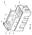
- FIG. 10 is a front assembled perspective view of the flowing electrolyte reservoir system 500 of a flowing electrolyte battery, according to an alternative embodiment of the present invention.
- advantages of some embodiments of the present invention include improved robustness, safety and efficiency, and reduced size and weight of flowing electrolyte battery systems.
- a reduced need for external plumbing hoses and fixtures both reduces the risk of electrolyte leaks and decreases the costs of the flowing electrolyte reservoir systems.
Description
- The present invention relates to flowing electrolyte batteries. In particular, although not exclusively, the invention relates to a flowing electrolyte reservoir system having a tank within a tank.
- Batteries used in stand alone power supply systems are commonly lead-acid batteries. However, lead-acid batteries have limitations in terms of performance and environmental safety. For example, typical lead-acid batteries often have very short lifetimes in hot climate conditions, especially when they are occasionally fully discharged. Lead-acid batteries are also environmentally hazardous, since lead is a major component of lead-acid batteries and can cause serious environmental problems during manufacturing and disposal.
- Flowing electrolyte batteries, such as zinc-bromine batteries, zinc-chlorine batteries, and vanadium flow batteries, offer a potential to overcome the above mentioned limitations of lead-acid batteries. In particular, the useful lifetime of flowing electrolyte batteries is not affected by deep discharge applications, and the energy to weight ratio of flowing electrolyte batteries is up to six times higher than that of lead-acid batteries.
- A flowing electrolyte battery, like a lead acid battery, comprises a stack of cells that produce a total voltage higher than that of individual cells. But unlike a lead acid battery, cells in a flowing electrolyte battery are hydraulically connected through an electrolyte circulation path.
- Referring to
FIG. 1 , a flow diagram illustrates a basic zinc-bromine flowingelectrolyte battery 100, as known according to the prior art. The zinc-bromine battery 100 includes a negativeelectrolyte circulation path 105 and an independent positiveelectrolyte circulation path 110. The negativeelectrolyte circulation path 105 contains zinc ions as an active chemical, and the positiveelectrolyte circulation path 110 contains bromine ions as an active chemical. The zinc-bromine battery 100 also comprises anegative electrolyte pump 115, apositive electrolyte pump 120, a negative zinc electrolyte (anolyte)tank 125, and a positive bromine electrolyte (catholyte)tank 130. A complexing agent is generally added to the bromine electrolyte to form a polybromide complex that reduces the reactivity and vapour pressure of elemental bromine. - To obtain high voltage, the zinc-
bromine battery 100 further comprises a stack of cells connected in a bipolar arrangement. For example, acell 135 compriseshalf cells bipolar electrode plate 155 and a microporous separator plate 165. The zinc-bromine battery 100 then has a positive polarity end at acollector electrode plate 160, and a negative polarity end at anothercollector electrode plate 150. - A chemical reaction in a positive half cell, such as the
half cell 145, during charging can be described according to the following equation:
electrolyte circulation path 110 and is then stored in the positivebromine electrolyte tank 130. A chemical reaction in a negative half cell, such as thehalf cell 140, during charging can be described according to the following equation:
metallic zinc layer 170 is thus formed on thecollector electrode plate 150 in contact with the negativeelectrolyte circulation path 105. Chemical reactions in thehalf cells - The prior art discloses various approaches for packaging flowing electrolyte battery systems, including various standard sizes and positions of the electrolyte storage tanks. Generally, two independent tanks, one for an anolyte and one for a catholyte, are arranged adjacent to each other and to a battery cell stack. Appropriate "plumbing", including pumps and hoses, is then used to circulate the electrolytes from the storage tanks, through the cell stack, and back to the storage tanks. However, such conventional shapes and arrangements of electrolyte storage tanks can cause numerous problems, including safety concerns related to leaking electrolyte, excessive plumbing costs, wasted materials, high manufacturing costs, and over-sized systems.
-
US 4,418,128 A (Fujii Toshinobu [JP]) 29 November 1983 (1983-11-29) discloses an electrolyte circulation type metal-bromine secondary battery of the kind in which the negatively active material is a metal and the anode electrolyte storage tank comprises an anode electrolyte zone and a complexing agent zone having a cross-sectional area smaller than that of the anode electrolyte zone. -
US 4,400,448 A (Einstein Harry [US] et al) 23 August 1983 (1983-08-23) discloses an electrochemical cell construction featuring a co-extruded plastic electrode in an interleaved construction with an integral separator-spacer. Also featured is a leak and impact resistant construction for preventing the spill of corrosive materials in the event of rupture. - Patent Abstracts of Japan &
JP 63, 016573, A, (Agency of Ind Science & Technol et al), 23 January 1988 - There is therefore a need to overcome or alleviate many of the above discussed problems associated with flowing electrolyte batteries of the prior art.
- Therefore, an object of the present invention is to overcome or alleviate one or more limitations of the prior art including providing improved flowing electrolyte reservoir systems for circulating electrolyte through a battery cell stack, to reduce manufacturing costs, increase safety and improve structural robustness of electrolyte tanks, and reduce tank size and weight.
- The present invention is a flowing electrolyte reservoir system for a flowing electrolyte battery according to claim 1. The system comprises:
- a battery cell stack comprising a negative electrolyte input port and a negative electrolyte output port;
- an outer tank positioned beneath the battery cell stack; and
- an inner tank positioned inside the outer tank and beneath the battery cell stack;
- wherein the negative electrolyte input port and the negative electrolyte output port of the battery cell stack are positioned directly above the outer tank and are not positioned directly above the inner tank.
- Optionally, the inner tank is transversely positioned between opposite corners of the outer tank and beneath opposite corners of the battery cell stack.
- Optionally, the system includes a first pump positioned on top of the outer tank and adjacent the battery cell stack and a second pump positioned on top of the inner tank and adjacent the battery cell stack.
- Optionally, the outer tank contains zinc electrolyte and the inner tank contains bromine electrolyte.
- Optionally, the outer tank and the inner tank are made of rotational moulded plastic.
- Optionally, the outer tank and the inner tank share a common lid.
- Optionally, the outer tank and the inner tank are complete, separable tanks and the inner tank fits into a void of the outer tank.
- Optionally, a raised lip is integral to an edge of the outer tank.
- Optionally, a bottom surface of the inner tank is sloped toward an electrolyte collection region.
- Optionally, an upper part of the inner and outer tanks form walls of a cavity for a cooling structure.
- Optionally, the walls of a cavity for a cooling structure include a hole for mounting a cooling fan.
- To assist in understanding the invention and to enable a person skilled in the art to put the invention into practical effect, preferred embodiments of the invention are described below by way of example only with reference to the accompanying drawings, in which:
-
FIG. 1 is a diagram illustrating a basic zinc-bromine flowing electrolyte battery, as known according to the prior art; -
FIG. 2 is a diagram illustrating a top view of a flowing electrolyte reservoir system of a flowing electrolyte battery, including hidden detail, according to some embodiments of the present invention; -
FIG. 3 is a side cross-sectional view of the Section A-A ofFIG. 1 illustrating a circulation path of zinc electrolyte in a flowing electrolyte reservoir system, according to some embodiments of the present invention; -
FIG. 4 is a side cross-sectional view of the Section B-B ofFIG. 1 illustrating a circulation path of bromine electrolyte in a flowing electrolyte reservoir system, according to some embodiments of the present invention. -
FIG. 5 is a diagram illustrating a top view of a flowingelectrolyte reservoir system 500, according to an embodiment of the present invention. -
FIG. 6 is a side cross-sectional view of the Section C-C ofFIG. 5 illustrating a circulation path of zinc electrolyte in the flowing electrolyte reservoir system, according to an embodiment of the present invention. -
FIG. 7 is a side cross-sectional view of the Section D-D ofFIG. 5 illustrating a circulation path of bromine electrolyte in the flowing electrolyte reservoir system, according to an alternative embodiment of the present invention. -
FIG. 8 is a front exploded perspective view of the flowing electrolyte reservoir system ofFIG. 5 of a flowing electrolyte battery, according to an alternative embodiment of the present invention. -
FIG. 9 is a rear exploded perspective view of the flowing electrolyte reservoir system ofFIG. 5 of a flowing electrolyte battery, according to an alternative embodiment of the present invention. -
FIG. 10 is a front assembled perspective view of the flowing electrolyte reservoir system ofFIG. 5 of a flowing electrolyte battery, according to an alternative embodiment of the present invention. - Those skilled in the art will appreciate that minor deviations from the layout of components as illustrated in the drawings will not detract from the proper functioning of the disclosed embodiments of the present invention.
- Embodiments of the present invention comprise a cell stack for a flowing electrolyte battery. Elements of the invention are illustrated in concise outline form in the drawings, showing only those specific details that are necessary to understanding the embodiments of the present invention, but so as not to clutter the disclosure with excessive detail that will be obvious to those of ordinary skill in the art in light of the present description.
- In this patent specification, adjectives such as first and second, left and right, front and back, top and bottom, etc., are used solely to define one element or method step from another element or method step without necessarily requiring a specific relative position or sequence that is described by the adjectives. Words such as "comprises" or "includes" are not used to define an exclusive set of elements or method steps. Rather, such words merely define a minimum set of elements or method steps included in a particular embodiment of the present invention.
- Referring to
FIG. 2 , a diagram illustrates a top view of a flowingelectrolyte reservoir system 200 of a flowing electrolyte battery, including hidden detail, according to some embodiments of the present invention. Thesystem 200 includes acell stack 205, an inner tank in the form of abromine electrolyte tank 210, and an outer tank in the form of azinc electrolyte tank 215. Abromine electrolyte pump 220 is positioned above thebromine electrolyte tank 210, and azinc electrolyte pump 225 is positioned above thezinc electrolyte tank 215. - A
zinc input port 230 enables zinc electrolyte to flow from thezinc electrolyte tank 215 to thecell stack 205, and azinc output port 235 enables zinc electrolyte to flow from thecell stack 205 to thezinc electrolyte tank 215. Similarly, abromine input port 240 enables bromine electrolyte to flow from thebromine electrolyte tank 210 to thecell stack 205, and abromine output port 245 enables bromine electrolyte to flow from thecell stack 205 to thebromine electrolyte tank 210. - Referring to
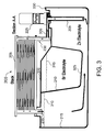
FIG. 3 , a side cross-sectional view of the Section A-A ofFIG. 1 illustrates a circulation path of zinc electrolyte in the flowingelectrolyte reservoir system 200, according to some embodiments of the present invention. As shown, zinc electrolyte near the bottom of thezinc electrolyte tank 215 enters anintake tube 305 and is then pumped by thezinc electrolyte pump 225 to thezinc input port 230. As shown by the arrows, the zinc electrolyte then flows through thecell stack 205 between various electrode plates, and out thezinc output port 235 to return to thezinc electrolyte tank 215. - Both the
bromine electrolyte tank 210 and thezinc electrolyte tank 215 share acommon lid 320. Further, abottom surface 325 thebromine electrolyte tank 210 can be sloped relative to a bottom surface of the flowingelectrolyte reservoir system 200 to improve collection and handling of the bromine complex. -
Lines electrolyte input port 230 and the zincelectrolyte output port 235 of thebattery cell stack 205 are directly above thezinc electrolyte tank 215 and are not directly above thebromine electrolyte tank 210. That enables the zinc electrolyte to flow directly from thezinc electrolyte tank 215 to and from thebattery cell stack 205 with only minimal "plumbing" apparatus such as hoses and fittings. Furthermore, any leaks in such plumbing are more likely to be self-contained and not result in cross contamination of electrolyte between thezinc electrolyte tank 215 and thebromine electrolyte tank 210. - Also, a raised
lip 330 along edges of thezinc electrolyte tank 215 enables potential leaks from thecell stack 205, thepumps other plumbing hoses 335 to be effectively collected and retained on the top of thelid 320. That can eliminate the need for additional containment trays under both thebromine electrolyte tank 210 and thezinc electrolyte tank 215. - Referring to
FIG. 4 , a side cross-sectional view of the Section B-B ofFIG. 1 illustrates a circulation path of bromine electrolyte in the flowingelectrolyte reservoir system 200, according to some embodiments of the present invention. As shown, bromine electrolyte near the bottom of thebromine electrolyte tank 210 enters anintake tube 405 and is then pumped by thebromine electrolyte pump 220 to thebromine input port 240. As shown by the arrows, the bromine electrolyte then flows through thecell stack 205 between various electrode plates, and out thebromine output port 245 to return to thebromine electrolyte tank 210. - As shown in
FIG. 2 , electrolyte generally flows transversely through thebattery cell stack 205, such as zinc electrolyte entering atport 230 and exiting atport 235, and bromine electrolyte entering atport 240 and exiting atport 245. By locating thebromine electrolyte tank 210 diagonally with respect to thebattery cell stack 205, the bromine electrolyte return via theport 245 coincides with thebromine electrolyte tank 210 directly below; similarly, the zinc electrolyte return via theport 235 coincides with thezinc electrolyte tank 215 directly below. Thus no additional plumbing is necessary to transfer electrolyte back from thebattery cell stack 205 to either thebromine electrolyte tank 210 or to thezinc electrolyte tank 215. - Also, it is known that generally the bromine complex of bromine electrolyte is significantly more chemically active than the zinc electrolyte. By positioning the
bromine electrolyte tank 210 inside of thezinc electrolyte tank 215, a risk of leakage of the bromine electrolyte outside of thesystem 200 is reduced, as the bromine electrolyte is effectively retained within a double-walled container. - Those skilled in the art will appreciate that there are various techniques for manufacturing the flowing
electrolyte reservoir system 200. For example, rotational moulding can be used to simultaneously and integrally form both thebromine electrolyte tank 210 and thezinc electrolyte tank 215. Thus only a single weld for securing thelid 320 can be used to complete the electrolyte enclosures of thesystem 200. Further, the tank-in-tank structure of the present invention provides improved overall stiffness of the tank walls, which permits the use of thinner wall thicknesses and less total weight. - Referring to
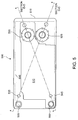
FIG. 5 , a diagram illustrates a top view of a flowingelectrolyte reservoir system 500 of a flowing electrolyte battery, including hidden detail, according to an alternative embodiment of the present invention. Thesystem 500 includes acell stack 640, an inner tank in the form of abromine electrolyte tank 510, and an outer tank in the form of azinc electrolyte tank 515. Abromine electrolyte pump 520 is positioned above thebromine electrolyte tank 510, and azinc electrolyte pump 525 is positioned above thezinc electrolyte tank 515. - A
zinc input port 530, shown inFIG. 6 positioned below thezinc electrolyte pump 525, enables zinc electrolyte to flow from thezinc electrolyte tank 515 to the cell stack, and azinc output port 535 enables zinc electrolyte to flow from the cell stack to thezinc electrolyte tank 515. Similarly, abromine input port 540, shown inFIG. 7 positioned below thebromine electrolyte pump 520, enables bromine electrolyte to flow from thebromine electrolyte tank 510 to the cell stack, and abromine output port 545 enables bromine electrolyte to flow from the cell stack to thebromine electrolyte tank 510. - A bromine
gas collection tube 550 extends from thebromine electrolyte tank 510. This enables bromine gas to be exhausted from thebromine electrolyte tank 510 if, for example due to abnormal operation, pressure builds up, advantageously through a pressure sensitive relief valve. Similarly, a zincgas collection tube 555 extends from thezinc electrolyte tank 515. This enables zinc gas to be exhausted from thezinc electrolyte tank 515 if pressure builds up, advantageously through a pressure sensitive relief valve. - Referring to
FIG. 6 , a side cross-sectional view of the Section C-C ofFIG. 5 illustrates a circulation path of zinc electrolyte in the flowingelectrolyte reservoir system 500, according to an alternative embodiment of the present invention. As shown, zinc electrolyte enters anintake tube 605 and is then pumped by thezinc electrolyte pump 525 to thezinc input port 530. As shown by the arrows, the zinc electrolyte then flows through thecell stack 640 between various electrode plates, and out thezinc output port 535 to return to thezinc electrolyte tank 515. - Both the
bromine electrolyte tank 510 and thezinc electrolyte tank 515 are complete and separable tanks. Further, abottom surface 625 thebromine electrolyte tank 510 can be sloped relative to a bottom surface of the flowingelectrolyte reservoir system 200 to improve collection and handling of the bromine complex. -
Lines electrolyte input port 530 and the zincelectrolyte output port 535 of thebattery cell stack 640 are directly above thezinc electrolyte tank 515 and are not directly above thebromine electrolyte tank 510. That enables the zinc electrolyte to flow directly from thezinc electrolyte tank 515 to and from thebattery cell stack 640 with only minimal "plumbing" apparatus such as hoses and fittings. Furthermore, any leaks in such plumbing are more likely to be self-contained and not result in cross contamination of electrolyte between thezinc electrolyte tank 515 and thebromine electrolyte tank 510. - Also, a raised
lip 630 along edges of thezinc electrolyte tank 515 enables potential leaks from thebromine electrolyte tank 510, thecell stack 640, thepumps other plumbing hoses 635 to be effectively collected and retained in the top ofzinc electrolyte tank 515. That can eliminate the need for additional containment trays under both thebromine electrolyte tank 510 and thezinc electrolyte tank 515. - Referring to
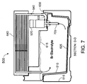
FIG. 7 , a side cross-sectional view of the Section D-D ofFIG. 5 illustrates a circulation path of bromine electrolyte in the flowingelectrolyte reservoir system 500, according to an alternative embodiment of the present invention. As shown, bromine electrolyte enters anintake tube 705 and is then pumped by thebromine electrolyte pump 520 to thebromine input port 540. As shown by the arrows, the bromine electrolyte then flows through thecell stack 640 between various electrode plates, and out thebromine output port 545 to return to thebromine electrolyte tank 510. - Electrolyte generally flows transversely through the
battery cell stack 640, such as zinc electrolyte entering atport 530 and exiting atport 535, and bromine electrolyte entering atport 540 and exiting atport 545. By locating thebromine electrolyte tank 510 diagonally with respect to thebattery cell stack 640, the bromine electrolyte return via theport 545 coincides with thebromine electrolyte tank 510 directly below; similarly, the zinc electrolyte return via theport 535 coincides with thezinc electrolyte tank 515 directly below. Thus no additional plumbing is necessary to transfer electrolyte back from thebattery cell stack 640 to either thebromine electrolyte tank 510 or to thezinc electrolyte tank 515. -
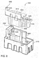
FIG. 8 is a front exploded perspective view of the flowingelectrolyte reservoir system 500 of a flowing electrolyte battery, according to an alternative embodiment of the present invention. - The
system 500 includes thebromine electrolyte tank 510, and thezinc electrolyte tank 515. Thezinc electrolyte tank 515 and thebromine electrolyte tank 510 are complete, separable tanks, and are shaped such that thebromine electrolyte 510 tank fits into a void of thezinc electrolyte tank 515. Abromine electrolyte pump 520 is positioned above thebromine electrolyte tank 510, and azinc electrolyte pump 525 is positioned above thezinc electrolyte tank 515. - An
upper surface 820 of thebromine electrolyte tank 510 and anupper surface 830 of thezinc electrolyte tank 515 define surfaces on which thecell stack 640 rests. Anupper part 810 of thebromine electrolyte tank 510 and anupper part 800 of thezinc electrolyte tank 515 form walls that, together with thecell stack 640, define a cavity for a cooling structure (not shown). - Electrolyte can be pumped through the cooling structure located in the cavity before being returned to the
zinc electrolyte tank 515 orbromine electrolyte tank 510. A fan, for example mounted in a preformed cavity, can be used to force air from one end of the cavity to the other end, through the cooling structure, guided by theupper parts bromine electrolyte tank 510, thezinc electrolyte tank 515 and thebattery cell stack 640. As will be understood by those having ordinary skill in the art, an example of a cooling structure is a series of long heat exchanger tubes having a large surface area with which the zinc and bromine electrolyte can exchange heat. -
FIG. 9 is a rear exploded perspective view of the flowingelectrolyte reservoir system 500 of a flowing electrolyte battery, according to an alternative embodiment of the present invention. -
FIG. 10 is a front assembled perspective view of the flowingelectrolyte reservoir system 500 of a flowing electrolyte battery, according to an alternative embodiment of the present invention. - In summary, advantages of some embodiments of the present invention include improved robustness, safety and efficiency, and reduced size and weight of flowing electrolyte battery systems. A reduced need for external plumbing hoses and fixtures both reduces the risk of electrolyte leaks and decreases the costs of the flowing electrolyte reservoir systems.
- The above description of various embodiments of the present invention is provided for purposes of description to one of ordinary skill in the related art. It is not intended to be exhaustive or to limit the invention to a single disclosed embodiment. As mentioned above, numerous alternatives and variations to the present invention will be apparent to those skilled in the art of the above teaching. Accordingly, while some alternative embodiments have been discussed specifically, other embodiments will be apparent or relatively easily developed by those of ordinary skill in the art.
Claims (11)
- A flowing electrolyte reservoir system (500) for a flowing electrolyte battery comprising:a battery cell stack (640) comprising a negative electrolyte input port (530) and a negative electrolyte output port (535);an outer tank positioned beneath the battery cell stack; andan inner tank positioned inside the outer tank and beneath the battery cell stack;wherein the negative electrolyte input port (530) and the negative electrolyte output port (535) of the battery cell stack (640) are positioned directly above the outer tank and are not positioned directly above the inner tank.
- A flowing electrolyte reservoir system according to claim 1 wherein the inner tank is transversely positioned between opposite corners of the outer tank and beneath opposite corners of the battery cell stack.
- A flowing electrolyte reservoir system according to claim 1 wherein the system includes a first pump positioned on top of the outer tank and adjacent the battery cell stack and a second pump positioned on top of the inner tank and adjacent the battery cell stack.
- A flowing electrolyte reservoir system according to claim 1 wherein the outer tank contains zinc electrolyte and the inner tank contains bromine electrolyte.
- A flowing electrolyte reservoir system according to claim 1 wherein the outer tank and the inner tank are made of rotational moulded plastic.
- A flowing electrolyte reservoir system according to claim 1 wherein the outer tank and the inner tank share a common lid.
- A flowing electrolyte reservoir system according to claim 1 wherein the outer tank and the inner tank are complete, separable tanks and wherein the inner tank fits into a void of the outer tank.
- A flowing electrolyte reservoir system according to claim 1 wherein a raised lip is integral to an edge of the outer tank.
- A flowing electrolyte reservoir system according to claim 1 wherein a bottom surface of the inner tank is sloped toward an electrolyte collection region.
- A flowing electrolyte reservoir system according to claim 1 wherein an upper part of the inner and outer tanks form walls of a cavity for a cooling structure.
- A flowing electrolyte reservoir system according to claim 10 wherein the walls of a cavity for a cooling structure include a hole for mounting a cooling fan.
Applications Claiming Priority (2)
| Application Number | Priority Date | Filing Date | Title |
|---|---|---|---|
| AU2009906174A AU2009906174A0 (en) | 2009-12-18 | Flowing electrolyte reservoir system | |
| PCT/AU2010/001698 WO2011072339A1 (en) | 2009-12-18 | 2010-12-17 | Flowing electrolyte reservoir system |
Publications (3)
| Publication Number | Publication Date |
|---|---|
| EP2510568A1 EP2510568A1 (en) | 2012-10-17 |
| EP2510568A4 EP2510568A4 (en) | 2014-12-17 |
| EP2510568B1 true EP2510568B1 (en) | 2016-09-14 |
Family
ID=44166650
Family Applications (1)
| Application Number | Title | Priority Date | Filing Date |
|---|---|---|---|
| EP10836850.7A Not-in-force EP2510568B1 (en) | 2009-12-18 | 2010-12-17 | Flowing electrolyte reservoir system |
Country Status (7)
| Country | Link |
|---|---|
| US (1) | US20120308867A1 (en) |
| EP (1) | EP2510568B1 (en) |
| JP (1) | JP5719851B2 (en) |
| CN (1) | CN102714295B (en) |
| AU (1) | AU2010333715B2 (en) |
| MY (1) | MY164638A (en) |
| WO (1) | WO2011072339A1 (en) |
Families Citing this family (11)
| Publication number | Priority date | Publication date | Assignee | Title |
|---|---|---|---|---|
| AU2014225947B2 (en) * | 2013-03-08 | 2017-10-19 | Primus Power Corporation | Reservoir for multiphase electrolyte flow control |
| GB201511695D0 (en) * | 2015-07-03 | 2015-08-19 | Renewable Energy Dynamics Technology Ltd | Improvements in redox flow batteries |
| KR101864863B1 (en) * | 2016-09-29 | 2018-06-05 | 롯데케미칼 주식회사 | Redox flow battery |
| US20190296383A1 (en) | 2017-03-13 | 2019-09-26 | Ifbattery Inc. | Electrochemical Cells |
| AT15942U1 (en) * | 2017-04-25 | 2018-10-15 | Edlmair Kunststofftechnik Gmbh | DOUBLE-WALLED STORAGE TANK FOR STATIONARY REDOX FLOW BATTERIES |
| EP3719906A4 (en) * | 2017-11-28 | 2020-11-18 | Sumitomo Electric Industries, Ltd. | Redox flow battery |
| EP3719907A4 (en) * | 2017-11-28 | 2020-12-09 | Sumitomo Electric Industries, Ltd. | Redox flow battery |
| WO2022031900A1 (en) * | 2020-08-06 | 2022-02-10 | Ifbattery Inc. | Battery system |
| US11309588B1 (en) * | 2020-12-11 | 2022-04-19 | GM Global Technology Operations LLC | Motion-generating mechanisms for desulfation of lead-acid batteries |
| US11916201B2 (en) | 2020-12-11 | 2024-02-27 | GM Global Technology Operations LLC | Motion-generating particles for desulfation of lead-acid batteries |
| US11309589B1 (en) | 2020-12-11 | 2022-04-19 | GM Global Technology Operations LLC | Motion-generating pumps for desulfation of lead-acid batteries |
Family Cites Families (13)
| Publication number | Priority date | Publication date | Assignee | Title |
|---|---|---|---|---|
| CA1174729A (en) * | 1981-06-01 | 1984-09-18 | Patrick G. Grimes | Electrochemical construction |
| US4400448A (en) * | 1981-06-01 | 1983-08-23 | Exxon Research And Engineering Co. | Electrochemical construction |
| US4418128A (en) * | 1982-03-25 | 1983-11-29 | Meidensha Electric Mfg. Co., Ltd. | Metal-bromine secondary battery |
| JPS62229665A (en) * | 1986-03-29 | 1987-10-08 | Sumitomo Electric Ind Ltd | Electrolyte circulating type secondary cell |
| JPS6316573A (en) * | 1986-07-09 | 1988-01-23 | Agency Of Ind Science & Technol | Electrolyte tank of electrolyte flow type battery |
| JPS6358771A (en) * | 1986-08-28 | 1988-03-14 | Agency Of Ind Science & Technol | Electrolyte tank of electrolyte flow type cell |
| JPH0546215Y2 (en) * | 1987-10-23 | 1993-12-02 | ||
| US5196276A (en) * | 1991-05-17 | 1993-03-23 | Eltech Systems Corporation | Reserve battery |
| US5601943A (en) * | 1995-10-26 | 1997-02-11 | Zbb Technologies, Inc. | Module for an aqueous battery system |
| AU767055B2 (en) * | 1998-05-06 | 2003-10-30 | Zbb Technologies Inc. | Spill and leak containment system for zinc-bromine battery |
| JP2001216994A (en) * | 2000-02-02 | 2001-08-10 | Sumitomo Electric Ind Ltd | Electrolyte tank for redox flow battery |
| US6455187B1 (en) * | 2000-10-03 | 2002-09-24 | Premium Power Acquisition Corporation | Recombinator for the re-acidification of an electrolyte stream in a flowing electrolyte zinc-bromine battery |
| WO2007114787A1 (en) * | 2006-03-30 | 2007-10-11 | Iut Global Pte Ltd | High solid thermophilic anaerobic digester |
-
2010
- 2010-12-17 AU AU2010333715A patent/AU2010333715B2/en active Active
- 2010-12-17 MY MYPI2012002670A patent/MY164638A/en unknown
- 2010-12-17 CN CN201080061971.7A patent/CN102714295B/en active Active
- 2010-12-17 US US13/516,542 patent/US20120308867A1/en not_active Abandoned
- 2010-12-17 WO PCT/AU2010/001698 patent/WO2011072339A1/en active Application Filing
- 2010-12-17 JP JP2012543416A patent/JP5719851B2/en active Active
- 2010-12-17 EP EP10836850.7A patent/EP2510568B1/en not_active Not-in-force
Also Published As
| Publication number | Publication date |
|---|---|
| CN102714295B (en) | 2016-02-17 |
| AU2010333715A1 (en) | 2012-06-28 |
| JP2013514604A (en) | 2013-04-25 |
| CN102714295A (en) | 2012-10-03 |
| EP2510568A1 (en) | 2012-10-17 |
| US20120308867A1 (en) | 2012-12-06 |
| AU2010333715B2 (en) | 2014-09-18 |
| MY164638A (en) | 2018-01-30 |
| EP2510568A4 (en) | 2014-12-17 |
| JP5719851B2 (en) | 2015-05-20 |
| WO2011072339A1 (en) | 2011-06-23 |
Similar Documents
| Publication | Publication Date | Title |
|---|---|---|
| EP2510568B1 (en) | Flowing electrolyte reservoir system | |
| TWI712207B (en) | Frame body, unit frame for redox flow battery and redox flow battery | |
| US7846573B2 (en) | Coolant manifold | |
| EP2293376B1 (en) | Battery cell assembly comprising heat exchanger with spiral flow path | |
| CN105914425A (en) | Battery system cooling systems and methods | |
| US11764423B2 (en) | Battery cooling panel for electric vehicles | |
| EP3761388A1 (en) | Battery pack | |
| CN219716902U (en) | Liquid flow battery electrolyte liquid storage tank with heat exchange structure | |
| KR102023914B1 (en) | Module type redox flow battery | |
| KR102023919B1 (en) | Module type redox flow battery | |
| US20240039026A1 (en) | Systems and methods for electrode assembly for redox flow battery system | |
| CN116706347B (en) | Aluminum fuel cell for rapidly heating reactor electrolyte and rapid heating method | |
| KR20140109615A (en) | A leakage protection for manifold, combined complex electrode cell and redox flow battery comprising thereof | |
| CN111799494B (en) | Fuel cell system | |
| CN114944505B (en) | Device for packaging flow battery | |
| CN219180661U (en) | Battery box, battery and power consumption device | |
| CN220510175U (en) | Battery and electricity utilization device | |
| CN220627925U (en) | Battery pack | |
| US20230095960A1 (en) | Battery pack | |
| KR20160079965A (en) | Stack cleansing apparatus for air-electrode battery | |
| KR20230116321A (en) | Closed-loop module structure of secondary battery using sodium solution | |
| JPH0648757Y2 (en) | Electrolyte circulation type laminated battery device | |
| CN116264298A (en) | Confluence mechanism and fuel cell system | |
| KR20160079963A (en) | Stack cleansing method for air-electrode battery | |
| CN107579187A (en) | A kind of anti-electrolyte percolated metal fuel cell |
Legal Events
| Date | Code | Title | Description |
|---|---|---|---|
| PUAI | Public reference made under article 153(3) epc to a published international application that has entered the european phase |
Free format text: ORIGINAL CODE: 0009012 |
|
| 17P | Request for examination filed |
Effective date: 20120710 |
|
| AK | Designated contracting states |
Kind code of ref document: A1 Designated state(s): AL AT BE BG CH CY CZ DE DK EE ES FI FR GB GR HR HU IE IS IT LI LT LU LV MC MK MT NL NO PL PT RO RS SE SI SK SM TR |
|
| DAX | Request for extension of the european patent (deleted) | ||
| RAP1 | Party data changed (applicant data changed or rights of an application transferred) |
Owner name: REDFLOW R&D PTY LTD |
|
| A4 | Supplementary search report drawn up and despatched |
Effective date: 20141118 |
|
| RIC1 | Information provided on ipc code assigned before grant |
Ipc: H01M 2/40 20060101ALI20141112BHEP Ipc: H01M 8/18 20060101ALI20141112BHEP Ipc: H01M 10/36 20100101AFI20141112BHEP Ipc: H01M 8/20 20060101ALI20141112BHEP |
|
| REG | Reference to a national code |
Ref country code: DE Ref legal event code: R079 Ref document number: 602010036492 Country of ref document: DE Free format text: PREVIOUS MAIN CLASS: H01M0002360000 Ipc: H01M0010360000 |
|
| RIC1 | Information provided on ipc code assigned before grant |
Ipc: H01M 8/18 20060101ALI20160212BHEP Ipc: H01M 8/20 20060101ALI20160212BHEP Ipc: H01M 2/40 20060101ALI20160212BHEP Ipc: H01M 10/36 20060101AFI20160212BHEP |
|
| GRAP | Despatch of communication of intention to grant a patent |
Free format text: ORIGINAL CODE: EPIDOSNIGR1 |
|
| INTG | Intention to grant announced |
Effective date: 20160404 |
|
| GRAS | Grant fee paid |
Free format text: ORIGINAL CODE: EPIDOSNIGR3 |
|
| GRAA | (expected) grant |
Free format text: ORIGINAL CODE: 0009210 |
|
| AK | Designated contracting states |
Kind code of ref document: B1 Designated state(s): AL AT BE BG CH CY CZ DE DK EE ES FI FR GB GR HR HU IE IS IT LI LT LU LV MC MK MT NL NO PL PT RO RS SE SI SK SM TR |
|
| REG | Reference to a national code |
Ref country code: GB Ref legal event code: FG4D |
|
| REG | Reference to a national code |
Ref country code: CH Ref legal event code: EP |
|
| REG | Reference to a national code |
Ref country code: CH Ref legal event code: NV Representative=s name: KAMINSKI HARMANN PATENTANWAELTE AG, LI |
|
| REG | Reference to a national code |
Ref country code: IE Ref legal event code: FG4D |
|
| REG | Reference to a national code |
Ref country code: AT Ref legal event code: REF Ref document number: 829883 Country of ref document: AT Kind code of ref document: T Effective date: 20161015 |
|
| REG | Reference to a national code |
Ref country code: NL Ref legal event code: FP |
|
| REG | Reference to a national code |
Ref country code: DE Ref legal event code: R096 Ref document number: 602010036492 Country of ref document: DE |
|
| REG | Reference to a national code |
Ref country code: FR Ref legal event code: PLFP Year of fee payment: 7 |
|
| REG | Reference to a national code |
Ref country code: LT Ref legal event code: MG4D |
|
| PG25 | Lapsed in a contracting state [announced via postgrant information from national office to epo] |
Ref country code: FI Free format text: LAPSE BECAUSE OF FAILURE TO SUBMIT A TRANSLATION OF THE DESCRIPTION OR TO PAY THE FEE WITHIN THE PRESCRIBED TIME-LIMIT Effective date: 20160914 Ref country code: RS Free format text: LAPSE BECAUSE OF FAILURE TO SUBMIT A TRANSLATION OF THE DESCRIPTION OR TO PAY THE FEE WITHIN THE PRESCRIBED TIME-LIMIT Effective date: 20160914 Ref country code: NO Free format text: LAPSE BECAUSE OF FAILURE TO SUBMIT A TRANSLATION OF THE DESCRIPTION OR TO PAY THE FEE WITHIN THE PRESCRIBED TIME-LIMIT Effective date: 20161214 Ref country code: HR Free format text: LAPSE BECAUSE OF FAILURE TO SUBMIT A TRANSLATION OF THE DESCRIPTION OR TO PAY THE FEE WITHIN THE PRESCRIBED TIME-LIMIT Effective date: 20160914 Ref country code: LT Free format text: LAPSE BECAUSE OF FAILURE TO SUBMIT A TRANSLATION OF THE DESCRIPTION OR TO PAY THE FEE WITHIN THE PRESCRIBED TIME-LIMIT Effective date: 20160914 |
|
| PGFP | Annual fee paid to national office [announced via postgrant information from national office to epo] |
Ref country code: IE Payment date: 20161216 Year of fee payment: 7 Ref country code: NL Payment date: 20161205 Year of fee payment: 7 Ref country code: CH Payment date: 20161215 Year of fee payment: 7 Ref country code: LU Payment date: 20161229 Year of fee payment: 7 Ref country code: MC Payment date: 20161223 Year of fee payment: 7 |
|
| PG25 | Lapsed in a contracting state [announced via postgrant information from national office to epo] |
Ref country code: GR Free format text: LAPSE BECAUSE OF FAILURE TO SUBMIT A TRANSLATION OF THE DESCRIPTION OR TO PAY THE FEE WITHIN THE PRESCRIBED TIME-LIMIT Effective date: 20161215 Ref country code: SE Free format text: LAPSE BECAUSE OF FAILURE TO SUBMIT A TRANSLATION OF THE DESCRIPTION OR TO PAY THE FEE WITHIN THE PRESCRIBED TIME-LIMIT Effective date: 20160914 Ref country code: LV Free format text: LAPSE BECAUSE OF FAILURE TO SUBMIT A TRANSLATION OF THE DESCRIPTION OR TO PAY THE FEE WITHIN THE PRESCRIBED TIME-LIMIT Effective date: 20160914 |
|
| PGFP | Annual fee paid to national office [announced via postgrant information from national office to epo] |
Ref country code: IT Payment date: 20161220 Year of fee payment: 7 |
|
| PG25 | Lapsed in a contracting state [announced via postgrant information from national office to epo] |
Ref country code: RO Free format text: LAPSE BECAUSE OF FAILURE TO SUBMIT A TRANSLATION OF THE DESCRIPTION OR TO PAY THE FEE WITHIN THE PRESCRIBED TIME-LIMIT Effective date: 20160914 Ref country code: EE Free format text: LAPSE BECAUSE OF FAILURE TO SUBMIT A TRANSLATION OF THE DESCRIPTION OR TO PAY THE FEE WITHIN THE PRESCRIBED TIME-LIMIT Effective date: 20160914 |
|
| PG25 | Lapsed in a contracting state [announced via postgrant information from national office to epo] |
Ref country code: SM Free format text: LAPSE BECAUSE OF FAILURE TO SUBMIT A TRANSLATION OF THE DESCRIPTION OR TO PAY THE FEE WITHIN THE PRESCRIBED TIME-LIMIT Effective date: 20160914 Ref country code: BG Free format text: LAPSE BECAUSE OF FAILURE TO SUBMIT A TRANSLATION OF THE DESCRIPTION OR TO PAY THE FEE WITHIN THE PRESCRIBED TIME-LIMIT Effective date: 20161214 Ref country code: PL Free format text: LAPSE BECAUSE OF FAILURE TO SUBMIT A TRANSLATION OF THE DESCRIPTION OR TO PAY THE FEE WITHIN THE PRESCRIBED TIME-LIMIT Effective date: 20160914 Ref country code: SK Free format text: LAPSE BECAUSE OF FAILURE TO SUBMIT A TRANSLATION OF THE DESCRIPTION OR TO PAY THE FEE WITHIN THE PRESCRIBED TIME-LIMIT Effective date: 20160914 Ref country code: IS Free format text: LAPSE BECAUSE OF FAILURE TO SUBMIT A TRANSLATION OF THE DESCRIPTION OR TO PAY THE FEE WITHIN THE PRESCRIBED TIME-LIMIT Effective date: 20170114 Ref country code: BE Free format text: LAPSE BECAUSE OF FAILURE TO SUBMIT A TRANSLATION OF THE DESCRIPTION OR TO PAY THE FEE WITHIN THE PRESCRIBED TIME-LIMIT Effective date: 20160914 Ref country code: PT Free format text: LAPSE BECAUSE OF FAILURE TO SUBMIT A TRANSLATION OF THE DESCRIPTION OR TO PAY THE FEE WITHIN THE PRESCRIBED TIME-LIMIT Effective date: 20170116 Ref country code: ES Free format text: LAPSE BECAUSE OF FAILURE TO SUBMIT A TRANSLATION OF THE DESCRIPTION OR TO PAY THE FEE WITHIN THE PRESCRIBED TIME-LIMIT Effective date: 20160914 Ref country code: CZ Free format text: LAPSE BECAUSE OF FAILURE TO SUBMIT A TRANSLATION OF THE DESCRIPTION OR TO PAY THE FEE WITHIN THE PRESCRIBED TIME-LIMIT Effective date: 20160914 |
|
| REG | Reference to a national code |
Ref country code: DE Ref legal event code: R097 Ref document number: 602010036492 Country of ref document: DE |
|
| PLBE | No opposition filed within time limit |
Free format text: ORIGINAL CODE: 0009261 |
|
| STAA | Information on the status of an ep patent application or granted ep patent |
Free format text: STATUS: NO OPPOSITION FILED WITHIN TIME LIMIT |
|
| PG25 | Lapsed in a contracting state [announced via postgrant information from national office to epo] |
Ref country code: DK Free format text: LAPSE BECAUSE OF FAILURE TO SUBMIT A TRANSLATION OF THE DESCRIPTION OR TO PAY THE FEE WITHIN THE PRESCRIBED TIME-LIMIT Effective date: 20160914 |
|
| 26N | No opposition filed |
Effective date: 20170615 |
|
| PG25 | Lapsed in a contracting state [announced via postgrant information from national office to epo] |
Ref country code: SI Free format text: LAPSE BECAUSE OF FAILURE TO SUBMIT A TRANSLATION OF THE DESCRIPTION OR TO PAY THE FEE WITHIN THE PRESCRIBED TIME-LIMIT Effective date: 20160914 |
|
| REG | Reference to a national code |
Ref country code: FR Ref legal event code: PLFP Year of fee payment: 8 |
|
| PG25 | Lapsed in a contracting state [announced via postgrant information from national office to epo] |
Ref country code: HU Free format text: LAPSE BECAUSE OF FAILURE TO SUBMIT A TRANSLATION OF THE DESCRIPTION OR TO PAY THE FEE WITHIN THE PRESCRIBED TIME-LIMIT; INVALID AB INITIO Effective date: 20101217 Ref country code: CY Free format text: LAPSE BECAUSE OF FAILURE TO SUBMIT A TRANSLATION OF THE DESCRIPTION OR TO PAY THE FEE WITHIN THE PRESCRIBED TIME-LIMIT Effective date: 20160914 |
|
| PG25 | Lapsed in a contracting state [announced via postgrant information from national office to epo] |
Ref country code: TR Free format text: LAPSE BECAUSE OF FAILURE TO SUBMIT A TRANSLATION OF THE DESCRIPTION OR TO PAY THE FEE WITHIN THE PRESCRIBED TIME-LIMIT Effective date: 20160914 Ref country code: MK Free format text: LAPSE BECAUSE OF FAILURE TO SUBMIT A TRANSLATION OF THE DESCRIPTION OR TO PAY THE FEE WITHIN THE PRESCRIBED TIME-LIMIT Effective date: 20160914 |
|
| REG | Reference to a national code |
Ref country code: CH Ref legal event code: PL |
|
| REG | Reference to a national code |
Ref country code: NL Ref legal event code: MM Effective date: 20180101 |
|
| REG | Reference to a national code |
Ref country code: IE Ref legal event code: MM4A |
|
| PG25 | Lapsed in a contracting state [announced via postgrant information from national office to epo] |
Ref country code: MT Free format text: LAPSE BECAUSE OF NON-PAYMENT OF DUE FEES Effective date: 20161217 Ref country code: LU Free format text: LAPSE BECAUSE OF NON-PAYMENT OF DUE FEES Effective date: 20171217 Ref country code: NL Free format text: LAPSE BECAUSE OF NON-PAYMENT OF DUE FEES Effective date: 20180101 |
|
| PG25 | Lapsed in a contracting state [announced via postgrant information from national office to epo] |
Ref country code: IT Free format text: LAPSE BECAUSE OF NON-PAYMENT OF DUE FEES Effective date: 20171217 Ref country code: IE Free format text: LAPSE BECAUSE OF NON-PAYMENT OF DUE FEES Effective date: 20171217 Ref country code: AL Free format text: LAPSE BECAUSE OF FAILURE TO SUBMIT A TRANSLATION OF THE DESCRIPTION OR TO PAY THE FEE WITHIN THE PRESCRIBED TIME-LIMIT Effective date: 20160914 |
|
| PG25 | Lapsed in a contracting state [announced via postgrant information from national office to epo] |
Ref country code: LI Free format text: LAPSE BECAUSE OF NON-PAYMENT OF DUE FEES Effective date: 20171231 Ref country code: CH Free format text: LAPSE BECAUSE OF NON-PAYMENT OF DUE FEES Effective date: 20171231 |
|
| PG25 | Lapsed in a contracting state [announced via postgrant information from national office to epo] |
Ref country code: MC Free format text: LAPSE BECAUSE OF NON-PAYMENT OF DUE FEES Effective date: 20180102 |
|
| REG | Reference to a national code |
Ref country code: AT Ref legal event code: UEP Ref document number: 829883 Country of ref document: AT Kind code of ref document: T Effective date: 20160914 |
|
| PGFP | Annual fee paid to national office [announced via postgrant information from national office to epo] |
Ref country code: DE Payment date: 20191203 Year of fee payment: 10 |
|
| PGFP | Annual fee paid to national office [announced via postgrant information from national office to epo] |
Ref country code: FR Payment date: 20191128 Year of fee payment: 10 |
|
| PGFP | Annual fee paid to national office [announced via postgrant information from national office to epo] |
Ref country code: AT Payment date: 20191125 Year of fee payment: 10 |
|
| PGFP | Annual fee paid to national office [announced via postgrant information from national office to epo] |
Ref country code: GB Payment date: 20191213 Year of fee payment: 10 |
|
| REG | Reference to a national code |
Ref country code: DE Ref legal event code: R119 Ref document number: 602010036492 Country of ref document: DE |
|
| REG | Reference to a national code |
Ref country code: AT Ref legal event code: MM01 Ref document number: 829883 Country of ref document: AT Kind code of ref document: T Effective date: 20201217 |
|
| GBPC | Gb: european patent ceased through non-payment of renewal fee |
Effective date: 20201217 |
|
| PG25 | Lapsed in a contracting state [announced via postgrant information from national office to epo] |
Ref country code: AT Free format text: LAPSE BECAUSE OF NON-PAYMENT OF DUE FEES Effective date: 20201217 Ref country code: FR Free format text: LAPSE BECAUSE OF NON-PAYMENT OF DUE FEES Effective date: 20201231 |
|
| PG25 | Lapsed in a contracting state [announced via postgrant information from national office to epo] |
Ref country code: GB Free format text: LAPSE BECAUSE OF NON-PAYMENT OF DUE FEES Effective date: 20201217 Ref country code: DE Free format text: LAPSE BECAUSE OF NON-PAYMENT OF DUE FEES Effective date: 20210701 |