EP2509819B1 - Anordnung zum induktiven beladen eines energiespeichers fahrzeugs und ladestation - Google Patents
Anordnung zum induktiven beladen eines energiespeichers fahrzeugs und ladestation Download PDFInfo
- Publication number
- EP2509819B1 EP2509819B1 EP10776948.1A EP10776948A EP2509819B1 EP 2509819 B1 EP2509819 B1 EP 2509819B1 EP 10776948 A EP10776948 A EP 10776948A EP 2509819 B1 EP2509819 B1 EP 2509819B1
- Authority
- EP
- European Patent Office
- Prior art keywords
- arrangement according
- primary winding
- cover
- hood
- plate
- Prior art date
- Legal status (The legal status is an assumption and is not a legal conclusion. Google has not performed a legal analysis and makes no representation as to the accuracy of the status listed.)
- Active
Links
Images



Classifications
-
- B—PERFORMING OPERATIONS; TRANSPORTING
- B60—VEHICLES IN GENERAL
- B60L—PROPULSION OF ELECTRICALLY-PROPELLED VEHICLES; SUPPLYING ELECTRIC POWER FOR AUXILIARY EQUIPMENT OF ELECTRICALLY-PROPELLED VEHICLES; ELECTRODYNAMIC BRAKE SYSTEMS FOR VEHICLES IN GENERAL; MAGNETIC SUSPENSION OR LEVITATION FOR VEHICLES; MONITORING OPERATING VARIABLES OF ELECTRICALLY-PROPELLED VEHICLES; ELECTRIC SAFETY DEVICES FOR ELECTRICALLY-PROPELLED VEHICLES
- B60L53/00—Methods of charging batteries, specially adapted for electric vehicles; Charging stations or on-board charging equipment therefor; Exchange of energy storage elements in electric vehicles
- B60L53/30—Constructional details of charging stations
-
- B—PERFORMING OPERATIONS; TRANSPORTING
- B60—VEHICLES IN GENERAL
- B60L—PROPULSION OF ELECTRICALLY-PROPELLED VEHICLES; SUPPLYING ELECTRIC POWER FOR AUXILIARY EQUIPMENT OF ELECTRICALLY-PROPELLED VEHICLES; ELECTRODYNAMIC BRAKE SYSTEMS FOR VEHICLES IN GENERAL; MAGNETIC SUSPENSION OR LEVITATION FOR VEHICLES; MONITORING OPERATING VARIABLES OF ELECTRICALLY-PROPELLED VEHICLES; ELECTRIC SAFETY DEVICES FOR ELECTRICALLY-PROPELLED VEHICLES
- B60L53/00—Methods of charging batteries, specially adapted for electric vehicles; Charging stations or on-board charging equipment therefor; Exchange of energy storage elements in electric vehicles
- B60L53/10—Methods of charging batteries, specially adapted for electric vehicles; Charging stations or on-board charging equipment therefor; Exchange of energy storage elements in electric vehicles characterised by the energy transfer between the charging station and the vehicle
- B60L53/12—Inductive energy transfer
- B60L53/126—Methods for pairing a vehicle and a charging station, e.g. establishing a one-to-one relation between a wireless power transmitter and a wireless power receiver
-
- H—ELECTRICITY
- H02—GENERATION; CONVERSION OR DISTRIBUTION OF ELECTRIC POWER
- H02J—ELECTRIC POWER NETWORKS; CIRCUIT ARRANGEMENTS OR SYSTEMS FOR SUPPLYING OR DISTRIBUTING ELECTRIC POWER; SYSTEMS FOR STORING ELECTRIC ENERGY
- H02J50/00—Circuit arrangements or systems for wireless supply or distribution of electric power
- H02J50/10—Circuit arrangements or systems for wireless supply or distribution of electric power using inductive coupling
-
- H—ELECTRICITY
- H02—GENERATION; CONVERSION OR DISTRIBUTION OF ELECTRIC POWER
- H02J—ELECTRIC POWER NETWORKS; CIRCUIT ARRANGEMENTS OR SYSTEMS FOR SUPPLYING OR DISTRIBUTING ELECTRIC POWER; SYSTEMS FOR STORING ELECTRIC ENERGY
- H02J50/00—Circuit arrangements or systems for wireless supply or distribution of electric power
- H02J50/10—Circuit arrangements or systems for wireless supply or distribution of electric power using inductive coupling
- H02J50/12—Circuit arrangements or systems for wireless supply or distribution of electric power using inductive coupling of the resonant type
-
- H—ELECTRICITY
- H02—GENERATION; CONVERSION OR DISTRIBUTION OF ELECTRIC POWER
- H02J—ELECTRIC POWER NETWORKS; CIRCUIT ARRANGEMENTS OR SYSTEMS FOR SUPPLYING OR DISTRIBUTING ELECTRIC POWER; SYSTEMS FOR STORING ELECTRIC ENERGY
- H02J50/00—Circuit arrangements or systems for wireless supply or distribution of electric power
- H02J50/40—Circuit arrangements or systems for wireless supply or distribution of electric power using two or more transmitting or receiving devices
-
- H—ELECTRICITY
- H02—GENERATION; CONVERSION OR DISTRIBUTION OF ELECTRIC POWER
- H02J—ELECTRIC POWER NETWORKS; CIRCUIT ARRANGEMENTS OR SYSTEMS FOR SUPPLYING OR DISTRIBUTING ELECTRIC POWER; SYSTEMS FOR STORING ELECTRIC ENERGY
- H02J50/00—Circuit arrangements or systems for wireless supply or distribution of electric power
- H02J50/70—Circuit arrangements or systems for wireless supply or distribution of electric power involving the reduction of electric, magnetic or electromagnetic leakage fields
-
- H—ELECTRICITY
- H02—GENERATION; CONVERSION OR DISTRIBUTION OF ELECTRIC POWER
- H02J—ELECTRIC POWER NETWORKS; CIRCUIT ARRANGEMENTS OR SYSTEMS FOR SUPPLYING OR DISTRIBUTING ELECTRIC POWER; SYSTEMS FOR STORING ELECTRIC ENERGY
- H02J1/00—Circuit arrangements for DC mains or DC distribution networks
- H02J1/08—Three-wire DC power distribution systems; Systems having more than three wires
- H02J1/082—DC supplies with two or more different DC voltage levels
-
- Y—GENERAL TAGGING OF NEW TECHNOLOGICAL DEVELOPMENTS; GENERAL TAGGING OF CROSS-SECTIONAL TECHNOLOGIES SPANNING OVER SEVERAL SECTIONS OF THE IPC; TECHNICAL SUBJECTS COVERED BY FORMER USPC CROSS-REFERENCE ART COLLECTIONS [XRACs] AND DIGESTS
- Y02—TECHNOLOGIES OR APPLICATIONS FOR MITIGATION OR ADAPTATION AGAINST CLIMATE CHANGE
- Y02T—CLIMATE CHANGE MITIGATION TECHNOLOGIES RELATED TO TRANSPORTATION
- Y02T10/00—Road transport of goods or passengers
- Y02T10/60—Other road transportation technologies with climate change mitigation effect
- Y02T10/70—Energy storage systems for electromobility, e.g. batteries
-
- Y—GENERAL TAGGING OF NEW TECHNOLOGICAL DEVELOPMENTS; GENERAL TAGGING OF CROSS-SECTIONAL TECHNOLOGIES SPANNING OVER SEVERAL SECTIONS OF THE IPC; TECHNICAL SUBJECTS COVERED BY FORMER USPC CROSS-REFERENCE ART COLLECTIONS [XRACs] AND DIGESTS
- Y02—TECHNOLOGIES OR APPLICATIONS FOR MITIGATION OR ADAPTATION AGAINST CLIMATE CHANGE
- Y02T—CLIMATE CHANGE MITIGATION TECHNOLOGIES RELATED TO TRANSPORTATION
- Y02T10/00—Road transport of goods or passengers
- Y02T10/60—Other road transportation technologies with climate change mitigation effect
- Y02T10/7072—Electromobility specific charging systems or methods for batteries, ultracapacitors, supercapacitors or double-layer capacitors
-
- Y—GENERAL TAGGING OF NEW TECHNOLOGICAL DEVELOPMENTS; GENERAL TAGGING OF CROSS-SECTIONAL TECHNOLOGIES SPANNING OVER SEVERAL SECTIONS OF THE IPC; TECHNICAL SUBJECTS COVERED BY FORMER USPC CROSS-REFERENCE ART COLLECTIONS [XRACs] AND DIGESTS
- Y02—TECHNOLOGIES OR APPLICATIONS FOR MITIGATION OR ADAPTATION AGAINST CLIMATE CHANGE
- Y02T—CLIMATE CHANGE MITIGATION TECHNOLOGIES RELATED TO TRANSPORTATION
- Y02T90/00—Enabling technologies or technologies with a potential or indirect contribution to GHG emissions mitigation
- Y02T90/10—Technologies relating to charging of electric vehicles
- Y02T90/12—Electric charging stations
-
- Y—GENERAL TAGGING OF NEW TECHNOLOGICAL DEVELOPMENTS; GENERAL TAGGING OF CROSS-SECTIONAL TECHNOLOGIES SPANNING OVER SEVERAL SECTIONS OF THE IPC; TECHNICAL SUBJECTS COVERED BY FORMER USPC CROSS-REFERENCE ART COLLECTIONS [XRACs] AND DIGESTS
- Y02—TECHNOLOGIES OR APPLICATIONS FOR MITIGATION OR ADAPTATION AGAINST CLIMATE CHANGE
- Y02T—CLIMATE CHANGE MITIGATION TECHNOLOGIES RELATED TO TRANSPORTATION
- Y02T90/00—Enabling technologies or technologies with a potential or indirect contribution to GHG emissions mitigation
- Y02T90/10—Technologies relating to charging of electric vehicles
- Y02T90/14—Plug-in electric vehicles
Definitions
- the invention relates to an arrangement for inductive loading of an energy storage vehicle and a charging station.
- the invention is therefore the object of developing an arrangement for inductive loading of an energy storage vehicle and a charging station, the arrangement should be used safely in different climates.
- the object is achieved in the arrangement for inductive loading of an energy storage vehicle according to the features specified in claim 1 and in the charging station according to the features indicated in claim 15.
- an electronic circuit is provided inside a hood whose opening is arranged on the underside of the hood.
- Such a hood with electronic circuit is in DE 20 2007 004 293 U1 to see.
- the advantage here is that a protection against water or other liquids occurring on the ground is formed.
- a protection against flooding or in the bottom enclosure penetrating water is given because the hood so far the electronic circuit down, so in the direction of gravity, surmounted that even with fully filled bottom enclosure, the water pressure is not large enough to the liquid surface within the To raise the hood so far that the electronic circuit comes into contact with the liquid.
- the protection is otherwise accessible by means of the hood in a passive manner. It is particularly important that it requires only the presence of an airtight and preferably liquid-tight or watertight hood.
- the charging without galvanic connection executable increases security. Because of the non-contact design, it is also prevented that an electrical connector between the vehicle and stationary circuit is under water. The stationarily arranged in the ground circuit is safely executable, especially with fault current monitoring and appropriate shutdown.
- the electronic circuit is arranged on the inner wall of the top of the hood.
- the electronic circuit is supplied from a supply line with electrical energy, in particular wherein the supply line is looped through, so the electronic circuit is powered by a T-node.
- a supply line with electrical energy in particular wherein the supply line is looped through
- the electronic circuit is powered by a T-node.
- the hood is arranged on the underside of a lid, in particular a cover plate.
- a lid in particular a cover plate.
- the cover has a ferrite plate and a primary winding provided thereon.
- the advantage here is that the inductive coupling to Secondary coil of the consumer is improved, since the magnetic leakage flux is reduced.
- the electronic circuit impresses an alternating current into the primary winding, in particular an alternating current with a frequency between 10 and 500 kHz, in particular between 20 and 30 kHz.
- an alternating current with a frequency between 10 and 500 kHz, in particular between 20 and 30 kHz.
- the vehicle has a secondary winding, which is connected in such a capacity in series or in parallel such that the associated resonant frequency substantially corresponds to the frequency of the impressed in the primary winding 2 AC.
- the lid of a vehicle is run over.
- the advantage here is that thus the arrangement in streets or parking lots is providable.
- the cover can be placed and connected on a housing part, which has at least one lateral recess for the passage of a supply cable.
- a housing part which has at least one lateral recess for the passage of a supply cable.
- the supply cable outside the housing part is guided in a tube which leads through the recess of the housing part.
- the advantage here is that the cable is guided in the protected interior of the housing part.
- the hood is tight, in particular airtight executed.
- the advantage here is that air can not escape and thus the air pressure can not break down.
- the cover has a supporting part, in particular plate made of aluminum or steel, on the underside of the hood is fixed and on the upper side of the ferrite plate is arranged, on the upper side of the primary winding is arranged.
- a supporting part in particular plate made of aluminum or steel, on the underside of the hood is fixed and on the upper side of the ferrite plate is arranged, on the upper side of the primary winding is arranged.
- the lid is arranged by means of a rotary joint on the housing part.
- the arrangements are supplied in parallel are supplied via the supply line from a public utility network.
- the advantage here is that a voltage source can be used, in particular a low-frequency source of rotary voltage.
- next adjacent housing parts are connected by means of respective tube for carrying the supply cable, in particular wherein the respective tube is guided at its first axial end portion by a recess in a first housing part and at its second axial end portion by a recess in a second housing part ,
- the respective tube is guided at its first axial end portion by a recess in a first housing part and at its second axial end portion by a recess in a second housing part
- the lid has a supporting part, a plate made of plastic, on the underside of which the ferrite plate is arranged, on the upper side of which the primary winding is arranged, so that the primary winding is arranged between the plate made of plastic and the ferrite plate, wherein the primary winding is surrounded by potting compound, in particular hardened potting compound, wherein the side wall, in particular the hood, is connected to the carrier part, the potting compound and / or the ferrite plate, in particular, wherein the ferrite plate is made in several pieces.
- potting compound in particular hardened potting compound
- the plastic plate is stabilized by the cured on the underside of the plastic plate potting compound and thus designed to be overridden by the vehicle.
- the potting compound also fulfills the holding function for the ferrite plate and the primary conductor.
- the hood is fixed from below on the lid, ie on the side facing away from the primary winding side of the ferrite plate. It is even an at least additional integral connection of the hood with the potting compound produced and thus airtightness at this compound effected.
- a screw connection between hood part and cover can be provided.
- the bottom enclosure has a housing part 5 which can be closed with a cover 1.
- the housing part 5 is in this case formed of four side walls and has no upper part and no lower part. Thus, the outflow of liquid penetrated downwards is possible, so a seepage of the penetrated liquid.
- the Bodenein charged is arranged in series, for example in parking lots. In this case, it is placed so deep in the ground that it can be driven over by a vehicle, such as an automobile.
- the Bodenein stamped also formed with the appropriate strength, so that overriding is possible.
- it can be arranged in the middle of a parking space, so that the wheels of the vehicle can be positioned laterally spaced apart and the cover 1 thus comes to lie directly under the vehicle floor.
- the cover 1 comprises a primary winding 2 designed as a ring winding, which is placed on a ferrite plate.
- the winding is potted and / or arranged below a plastic plate.
- the ferrite plate is arranged on the side facing away from the vehicle of the primary winding 2.
- the cover 1 is screw-connected to the housing part 5.
- the means of a provided on the housing part 5 pivot hinged.
- an electronic circuit 3 is arranged in a hood 4, so that when penetrated into the housing part liquid this can not rise to the electronic circuit 3, since the hood 4 is connected airtight with the lid 1 and thus the ascending liquid through Air is displaced. Only when the pressure in the liquid rises to very high levels, the liquid level can rise so high that the electronic circuit comes into contact with the liquid. Rainwater occurring in the parking lot does not reach these high pressure values - even if it would infiltrate into the ground enclosure and in the underground, so at the bottom of the Bodenin charged, would not infiltrate and thus gradually fill the bottom enclosure completely.
- the side wall of the hood 4 is at least twice as long in the direction of gravity as the length of the electronic circuit 3 in this direction.
- a pressure in the liquid of at least about 1 bar is necessary to compress the air in the hood 4 so strong that the liquid level could wet the electronic circuit 3.
- a supply cable 7 is passed through a buried protective tube 6 through a recess of the housing part 5 and supplies the electronic circuit 3 with electrical energy.
- the supply cable preferably carries three-phase cables. Alternatively, the supply cable 7 performs only a single-phase AC line.
- the electronic circuit 3 comprises a rectifier whose rectified voltage feeds an inverter which generates a single-phase alternating voltage having a frequency between 10 and 500 kHz, preferably a frequency between 20 and 30 kHz. From this AC voltage, a gyrator is fed, whose resonant frequency substantially corresponds to the frequency and thus the output side is a power source.
- the vehicle has a secondary winding, to which such a capacitance is connected in series or in parallel such that the associated resonant frequency essentially corresponds to the frequency of the alternating current impressed into the primary winding 2.
- the transmitted electrical energy is used to charge an energy storage device.
- the supply line 7 is provided looped through.
- the electronic circuits 3 of the successively arranged in series Bodenag neutral urge are supplied in parallel. For this purpose, therefore, a T-node is executed within each hood 4.
Landscapes
- Engineering & Computer Science (AREA)
- Power Engineering (AREA)
- Computer Networks & Wireless Communication (AREA)
- Transportation (AREA)
- Mechanical Engineering (AREA)
- Physics & Mathematics (AREA)
- Electromagnetism (AREA)
- Charge And Discharge Circuits For Batteries Or The Like (AREA)
- Electric Propulsion And Braking For Vehicles (AREA)
- Arrangement Or Mounting Of Propulsion Units For Vehicles (AREA)
Description
- Die Erfindung betrifft eine Anordnung zum induktiven Beladen eines Energiespeichers Fahrzeugs und eine Ladestation.
- Es ist bekannt, Fahrzeuge mit einem Elektromotor auszustatten, der aus einem mitgeführten Energiespeicher versorgbar ist. Dieser muss beispielsweise beim Parken des Fahrzeuges über eine galvanische Verbindung aufgeladen werden.
- Der Erfindung liegt daher die Aufgabe zugrunde, eine Anordnung zum induktiven Beladen eines Energiespeichers Fahrzeugs und eine Ladestation weiterzubilden, wobei die Anordnung in verschiedenen Klimazonen sicher verwendbar sein soll.
- Erfindungsgemäß wird die Aufgabe bei der Anordnung zum induktiven Beladen eines Energiespeichers Fahrzeugs nach den in Anspruch 1 und bei der Ladestation nach den in Anspruch 15 angegebenen Merkmalen gelöst.
- Einige Merkmale der Anordnung zum induktiven Beladen eines Energiespeichers Fahrzeugs sind, dass eine elektronische Schaltung im Inneren einer Haube vorgesehen ist, deren Öffnung an der Unterseite der Haube angeordnet ist. Eine solche Haube mit elektronischer Schaltung ist in
DE 20 2007 004 293 U1 zu sehen. - Von Vorteil ist dabei, dass ein Schutz vor Wasser oder anderen am Boden auftretenden Flüssigkeiten ausgebildet ist. Dabei ist insbesondere ein Schutz gegen Hochwasser oder in die Bodeneinfassung eindringendes Wasser gegeben, da die Haube derart weit die elektronische Schaltung nach unten, also in Gravitationsrichtung, überragt, dass selbst bei voll gefüllter Bodeneinfassung der Wasserdruck nicht groß genug ist, um die Flüssigkeitsoberfläche innerhalb der Haube derart weit aufsteigen zu lassen, dass die elektronische Schaltung mit der Flüssigkeit in Kontakt kommt.
- Der Schutz ist im Übrigen mittels der Haube in passiver Weise erreichbar. Besonders wichtig ist dabei, dass er nur das Vorhandensein einer luftdichten und vorzugsweise flüssigkeitsdichten beziehungsweise wasserdichten Haube voraussetzt.
- Darüber hinaus ist das Aufladen ohne galvanische Verbindung ausführbar und somit die Sicherheit erhöht. Denn mittels der berührungslosen Ausführung ist es auch verhindert, dass eine elektrische Steckverbindung zwischen Fahrzeug und stationärer Schaltung unter Wasser zu liegen kommt. Die im Boden stationär angeordnete Schaltung ist sicher ausführbar, insbesondere auch mit Fehlerstromüberwachung und entsprechender Abschaltung.
- Bei einer vorteilhaften Ausgestaltung ist die elektronische Schaltung an der Innenwandung der Oberseite der Haube angeordnet. Von Vorteil ist dabei, dass somit der bestmögliche Schutz gegen in der Haube aufsteigendes Wasser erreichbar ist.
- Bei einer vorteilhaften Ausgestaltung wird die elektronische Schaltung aus einer Versorgungsleitung mit elektrischer Energie versorgt, insbesondere wobei die Versorgungsleitung durchgeschleift vorgesehen ist, also die elektronische Schaltung aus einem T-Knoten versorgt ist. Von Vorteil ist dabei, dass dabei wasserdichte Kabel verwendbar sind und infolge des Durchschleifens mehrere Anordnungen parallel versorgbar sind, also aus einer Spannungsquelle versorgbar sind. Es ist also das Öffentliche Netz als Versorgungsquelle verwendbar. Alternativ ist auch eine parallele Versorgung aller elektronischer Schaltungen der Anordnungen einer Ladestation ausführbar, wobei dann vorzugsweise eine Stromquelle zur Versorgung vorteilhaft ist. In diesem Fall wäre dann ein T-Knoten verzichtbar.
- Bei der Ausgestaltung ist die Haube an der Unterseite eines Deckels, insbesondere einer Deckelplatte, angeordnet. Von Vorteil ist dabei, dass die Haube mitsamt elektronischer Schaltung durch Abheben des Deckels von der restlichen Bodeneinfassung, insbesondere dem Gehäuseteil der Anordnung, zugänglich und somit wartbar, reparierbar oder austauschbar wird.
- Bei der Ausgestaltung weist der Deckel eine Ferritplatte und eine auf dieser vorgesehene Primärwicklung auf. Von Vorteil ist dabei, dass die induktive Kopplung zur Sekundärspule des Verbrauchers verbessert wird, da der magnetische Streufluss vermindert wird.
- Bei einer vorteilhaften Ausgestaltung prägt die elektronische Schaltung einen Wechselstrom in die Primärwicklung ein, insbesondere einen Wechselstrom mit einer Frequenz zwischen 10 und 500 kHz, insbesondere zwischen 20 und 30 kHz. Von Vorteil ist dabei, dass hohe Leistungen übertragbar sind, insbesondere mehrere Kilowatt, auf kleinem Volumen, insbesondere vom Boden an ein gewöhnliches Automobil, wobei die Sekundärspule am Boden des Fahrzeugs angeordnet ist innerhalb der von den Rädern begrenzten Bodenfläche des Fahrzeugs. Somit ist auf kompaktem Raumbereich eine hohe Leistung mit einfachen Mitteln berührungslos übertragbar. Zu Erzeugung des Wechselstroms sind außerdem nur gewöhnliche Leistungshalbleiter notwendig, die als Massenprodukt erhältlich sind.
- Bei einer vorteilhaften Ausgestaltung weist das Fahrzeug eine Sekundärwicklung auf, der eine derartige Kapazität in Reihe oder parallel derart zugeschaltet ist, dass die zugehörige Resonanzfrequenz im Wesentlichen der Frequenz des in die Primärwicklung 2 eingeprägten Wechselstromes entspricht. Von Vorteil ist dabei, dass auch bei Abweichung der Sekundärspule von ihrer optimalen Position relativ zur Primärwicklung oder sonstiger schwacher Kopplung ein hoher Wirkungsgrad bei der Übertragung erzielbar ist.
- Bei einer vorteilhaften Ausgestaltung ist der Deckel von einem Fahrzeug überfahrbar ausgeführt. Von Vorteil ist dabei, dass somit die Anordnung in Straßen oder Parkplätzen vorsehbar ist.
- Bei einer vorteilhaften Ausgestaltung ist der Deckel auf einem Gehäuseteil aufsetzbar und verbindbar, das zumindest eine seitliche Ausnehmung zur Durchführung eines Versorgungskabels aufweist. Von Vorteil ist dabei, dass das Kabel geschützt im Boden führbar ist, nämlich innerhalb des schützenden Rohrs.
- Bei einer vorteilhaften Ausgestaltung ist das Versorgungskabel außerhalb des Gehäuseteils in einem Rohr geführt, das durch die Ausnehmung des Gehäuseteils führt. Von Vorteil ist dabei, dass das Kabel in den geschützten Innenraum des Gehäuseteils geführt wird.
- Bei einer vorteilhaften Ausgestaltung ist die Haube dicht, insbesondere luftdicht, ausgeführt. Von Vorteil ist dabei, dass Luft nicht entweichen kann und somit der Luftdruck sich auch nicht abbauen kann.
- Bei einer vorteilhaften Ausgestaltung weist der Deckel ein Tragteil, insbesondere Platte aus Aluminium oder Stahl, auf, an dessen Unterseite die Haube befestigt ist und auf dessen Oberseite die Ferritplatte angeordnet ist, auf deren Oberseite die Primärwicklung angeordnet ist. Von Vorteil ist dabei, dass die Stabilität verbesserbar ist und die Ferritplatte eine stabile Grundlage aufweist.
- Bei einer vorteilhaften Ausgestaltung ist der Deckel mittels eines Drehgelenks am Gehäuseteil angeordnet. Von Vorteil ist dabei, dass durch einfaches Aufklappen die elektronische Schaltung zugänglich machbar ist.
- Wichtige Merkmale bei der Ladestation mit mehreren Anordnungen sind, dass die Anordnungen parallel versorgt sind über die Versorgungsleitung aus einem Öffentlichen Versorgungsnetz versorgt sind. Von Vorteil ist dabei, dass eine Spannungsquelle verwendbar ist, insbesondere eine niederfrequente Drehspannungsquelle.
- Bei einer vorteilhaften Ausgestaltung weist sind nächst benachbarte Gehäuseteile mittels jeweiligem Rohr verbunden zur Durchführung des Versorgungskabels, insbesondere wobei das jeweilige Rohr an seinem ersten axialen Endbereich durch eine Ausnehmung in einem ersten Gehäuseteil und an seinem zweiten axialen Endbereich durch eine Ausnehmung in einem zweiten Gehäuseteil geführt ist. Von Vorteil ist dabei, dass eine bodenverlegte geschützte Verbindung ausbildbar ist.
- Bei der Ausgestaltung weist der Deckel ein Tragteil, eine Platte aus Kunststoff auf, an dessen Unterseite die Ferritplatte angeordnet ist, auf deren Oberseite die Primärwicklung angeordnet ist, so dass die Primärwicklung zwischen der Platte aus Kunststoff und der Ferritplatte angeordnet ist,
wobei die Primärwicklung von Vergussmasse, insbesondere von ausgehärteter Vergussmasse, umgeben ist,
wobei die Seitenwandung, insbesondere die Haube, verbunden ist mit dem Tragteil, der Vergussmasse und/oder der Ferritplatte,
insbesondere wobei die Ferritplatte mehrstückig ausgeführt ist. Von Vorteil ist dabei, dass das Tragteil aus Kunststoff ist und somit induktive Kopplung zwischen Primärwicklung und Sekundärwicklung nicht oder zumindest fast nicht verschlechtert wird. Außerdem ist die Kunststoffplatte durch die an der Unterseite der Kunststoffplatt ausgehärtete Vergussmasse stabilisiert und somit vom Fahrzeug überfahrbar ausgestaltbar. Die Vergussmasse erfüllt des Weiteren auch die Haltefunktion für die Ferritplatte und den Primärleiter. Außerdem ist die Haube von unten am Deckel befestigt, also an der von der Primärwicklung abgewandten Seite der Ferritplatte. Es ist sogar ein zumindest zusätzliches stoffschlüssiges Verbinden der Haube mit der Vergussmasse herstellbar und somit Luftdichtheit an dieser Verbindung bewirkbar. Zusätzlich kann eine Schraubverbindung zwischen Haubenteil und Deckel vorgesehen werden. - Weitere Vorteile ergeben sich aus den Unteransprüchen. Die Erfindung ist nicht auf die Merkmalskombination der Ansprüche beschränkt. Für den Fachmann ergeben sich weitere sinnvolle Kombinationsmöglichkeiten von Ansprüchen und/oder einzelnen Anspruchsmerkmalen und/oder Merkmalen der Beschreibung und/oder der Figuren, insbesondere aus der Aufgabenstellung und/oder der sich durch Vergleich mit dem Stand der Technik stellenden Aufgabe.
- Die Erfindung wird nun anhand von Abbildungen näher erläutert:
- In der
Figur 1 ist das Prinzip der Erfindung schematisch skizziert, wobei drei Bodeneinfassungen in Reihe vorgesehen sind. - In
Figur 2 ist eine Bodeneinfassung mit aufgeklapptem Deckel 1 in Schrägansicht gezeigt. - In der
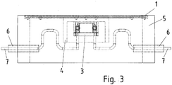
Figur 3 ist eine seitliche Durchsicht der Bodeneinfassung gezeigt. - In der
Figur 4 ist eine räumliche Durchsicht der Bodeneinfassung gezeigt. - Dabei weist die der Bodeneinfassung ein Gehäuseteil 5 auf, das mit einem Deckel 1 verschließbar ist.
- Das Gehäuseteil 5 ist hierbei aus vier Seitenwänden gebildet und weist kein Oberteil und kein Unterteil auf. Somit ist der Abfluss von eingedrungener Flüssigkeit nach unten ermöglicht, also ein Versickern der eingedrungenen Flüssigkeit.
- Die Bodeneinfassung wird in Reihe angeordnet, beispielsweise auf Parkplätzen. Dabei wird sie derart tief im Boden angeordnet, dass sie von einem Fahrzeug, wie beispielsweise Automobil, überfahrbar ist. Außerdem die Bodeneinfassung auch mit der entsprechenden Festigkeit ausgebildet, damit ein Überfahren ermöglicht ist. Insbesondere ist sie in der Mitte eines Parkplatzes anordenbar, so dass die Räder des Fahrzeugs seitlich beabstandet positionierbar sind und der Deckel 1 somit direkt unter dem Fahrzeugboden zu liegen kommt.
- Der Deckel 1 umfasst eine als Ringwicklung ausgeführte Primärwicklung 2, die auf einer Ferritplatte aufgelegt ist. Vorzugsweise ist die Wicklung vergossen und/oder unterhalb einer Kunststoffplatte angeordnet. Somit ist die Primärwicklung 2 geschützt vorgesehen. Die Ferritplatte ist auf der dem Fahrzeug abgewandten Seite der Primärwicklung 2 angeordnet.
- Der Deckel 1 ist schraubverbunden mit dem Gehäuseteil 5. Alternativ ist der mittels eines am Gehäuseteil 5 vorgesehenen Drehgelenks aufklappbar.
- An der Unterseite des Deckels 1 ist eine elektronische Schaltung 3 in einer Haube 4 angeordnet, so dass bei ins Gehäuseteil eingedrungener Flüssigkeit diese nicht aufsteigen kann zur elektronischen Schaltung 3, da die Haube 4 mit dem Deckel 1 luftdicht verbunden ist und somit die aufsteigende Flüssigkeit durch Luft verdrängt wird. Nur wenn der Druck in der Flüssigkeit auf sehr hohe Werte steigt, kann der Flüssigkeitspegel derart hoch steigen, dass die elektronische Schaltung mit der Flüssigkeit in Kontakt kommt. Auf dem Parkplatz auftretendes Regenwasser erreicht diese hohen Druckwerte nicht - auch wenn es in die Bodeneinfassung einfließende und im Untergrund, also an der Unterseite der Bodeneinfassung, nicht versickern würde und somit die Bodeneinfassung nach und nach gänzlich befüllen würde.
- Die Seitenwand der Haube 4 ist in Gravitationsrichtung mindestens doppelt so lang wie die Länge der elektronischen Schaltung 3 in dieser Richtung. Somit ist ein Druck in der Flüssigkeit von mindestens etwa 1 bar notwendig, um die Luft in der Haube 4 derart stark zu komprimieren, dass der Flüssigkeitsstand die elektronische Schaltung 3 benetzen könnte. Durch entsprechende Verlängerung der Haubenlänge in Gravitationsrichtung ist eine Erhöhung des kritischen Drucks erreichbar.
- Ein Versorgungskabel 7 wird durch ein bodenverlegtes schützendes Rohr 6 durch eine Ausnehmung des Gehäuseteils 5 geführt und versorgt die elektronische Schaltung 3 mit elektrischer Energie. Vorzugsweise führt das Versorgungskabel Drehstromleitungen. Alternativ führt das Versorgungskabel 7 nur eine einphasige Wechselstromleitung.
- Die elektronische Schaltung 3 weist einen Gleichrichter aus, dessen gleichgerichtete Spannung einen Wechselrichter speist, welcher eine einphasige Wechselspannung erzeugt, die eine Frequenz zwischen 10 und 500 kHz, vorzugsweise eine Frequenz zwischen 20 und 30 kHz, aufweist. Aus dieser Wechselspannung wird ein Gyratör gespeist, dessen Resonanzfrequenz im Wesentlichen der Frequenz entspricht und der somit ausgangsseitig eine Stromquelle darstellt.
- Mittels der so gebildeten Wechselstromquelle wird in die Primärwicklung 2 ein Wechselstrom eingeprägt.
- Das Fahrzeug weist eine Sekundärwicklung auf, der eine derartige Kapazität in Reihe oder parallel derart zugeschaltet ist, dass die zugehörige Resonanzfrequenz im Wesentlichen der Frequenz des in die Primärwicklung 2 eingeprägten Wechselstromes entspricht. Somit ist auch bei nicht optimaler Positionierung des Fahrzeuges, also einer verschlechterten induktiven Kopplung zwischen Primärwicklung 2 und Sekundärwicklung ein ausreichender Wirkungsgrad erreichbar bei der berührungslosen induktiven Energieübertragung ans Fahrzeug.
- Im Fahrzeug wird die übertragene elektrische Energie zum Laden eines Energiespeichers verwendet.
- Die Versorgungsleitung 7 ist durchgeschleift vorgesehen. Somit sind die elektronischen Schaltungen 3 der in Reihe hintereinander angeordneten Bodeneinfassungen parallel versorgbar. Hierzu ist also innerhalb jeder Haube 4 ein T-Knoten ausgeführt.
- Bei einem alternativen Ausführungsbeispiel wird statt dieser Parallelversorgung eine Reihenversorgung ausgeführt.
- Bei der Herstellung des Parkplatzes werden Vertiefungen in den Boden eingebracht, in welche jeweils ein Gehäuseteil 5 eingesetzt wird. Außerdem werden die Rohre zwischen den Gehäuseteilen 5 eingesetzt, wodurch die Versorgungsleitungen 7 geschützt führbar sind. Nach Ausführen der Verkabelung und Aufsetzen der mit Haube 4 und elektronischer Schaltung 3 versehenen vorgefertigten Deckel 1 auf das jeweilige Gehäuseteil 5 wird der Untergrund aufgefüllt und die befahrbare Bodenoberfläche gefertigt.
-
- 1 Deckel
- 2 Primärwicklung
- 3 elektronische Schaltung
- 4 Haube
- 5 Gehäuseteil
- 6 Rohr
- 7 Versorgungsleitung
Claims (16)
- Anordnung zum induktiven Beladen eines Energiespeichers Fahrzeugs,
wobei in der Anordnung eine elektronische Schaltung (3) im Inneren einer Haube (4) vorgesehen ist, deren Öffnung an der Unterseite der Haube (4) angeordnet ist,
wobei die Haube (4) an der Unterseite eines Deckels (1), insbesondere einer Deckelplatte, angeordnet ist, gekennzeichnet dadurch dass der Deckel (1) eine Ferritplatte und eine auf dieser vorgesehene Primärwicklung (2) aufweist, wobei der Deckel (1) ein Tragteil, welches als Platte aus Kunststoff ausgeführt ist, aufweist,
wobei an der Unterseite des Tragteils die Ferritplatte angeordnet ist, auf deren Oberseite die Primärwicklung (2) angeordnet ist, so dass die Primärwicklung (2) zwischen der Platte aus Kunststoff und der Ferritplatte angeordnet ist,
wobei die Primärwicklung (2) von Vergussmasse umgeben ist,
wobei die Seitenwand der Haube (4) verbunden ist mit dem Tragteil, der Vergussmasse und/oder der Ferritplatte. - Anordnung nach mindestens einem der vorangegangenen Ansprüche,
dadurch gekennzeichnet, dass
die elektronische Schaltung (3) an der Innenwandung der Oberseite der Haube (4) angeordnet ist. - Anordnung nach mindestens einem der vorangegangenen Ansprüche,
dadurch gekennzeichnet, dass
die elektronische Schaltung (3) aus einer Versorgungsleitung (7) mit elektrischer Energie versorgt wird, insbesondere wobei die Versorgungsleitung (7) durchgeschleift vorgesehen ist, also die elektronische Schaltung (3) aus einem T-Knoten versorgt ist. - Anordnung nach mindestens einem der vorangegangenen Ansprüche,
dadurch gekennzeichnet, dass
der Deckel (1) eine Deckelplatte ist. - Anordnung nach mindestens einem der vorangegangenen Ansprüche,
dadurch gekennzeichnet, dass
zwischen Primärwicklung (2) und Ferritplatte Vergussmasse vorgesehen ist. - Anordnung nach mindestens einem der vorangegangenen Ansprüche,
dadurch gekennzeichnet, dass
die elektronische Schaltung (3) einen Wechselstrom in die Primärwicklung (2) einprägt, insbesondere einen Wechselstrom mit einer Frequenz zwischen 10 und 500 kHz, insbesondere zwischen 20 und 30 kHz.. - Anordnung nach mindestens einem der vorangegangenen Ansprüche,
dadurch gekennzeichnet, dass
das Fahrzeug eine Sekundärwicklung aufweist, der eine derartige Kapazität in Reihe oder parallel derart zugeschaltet ist, dass die zugehörige Resonanzfrequenz im Wesentlichen der Frequenz des in die Primärwicklung (2) eingeprägten Wechselstromes entspricht. - Anordnung nach mindestens einem der vorangegangenen Ansprüche,
dadurch gekennzeichnet, dass
der Deckel (1) von einem Fahrzeug überfahrbar ausgeführt ist. - Anordnung nach mindestens einem der vorangegangenen Ansprüche,
dadurch gekennzeichnet, dass
der Deckel (1) auf einem Gehäuseteil (5) aufsetzbar und verbindbar ist, das zumindest eine seitliche Ausnehmung zur Durchführung eines Versorgungskabels aufweist. - Anordnung nach mindestens einem der vorangegangenen Ansprüche,
dadurch gekennzeichnet, dass
das Versorgungskabel außerhalb des Gehäuseteils (5) in einem Rohr (6) geführt ist, das durch die Ausnehmung des Gehäuseteils (5) führt. - Anordnung nach mindestens einem der vorangegangenen Ansprüche,
dadurch gekennzeichnet, dass
die Haube (4) dicht, insbesondere luftdicht, ausgeführt ist. - Anordnung nach mindestens einem der vorangegangenen Ansprüche,
dadurch gekennzeichnet, dass
die Primärwicklung (2) von ausgehärteter Vergussmasse umgeben ist,
wobei die Ferritplatte mehrstückig ausgeführt ist. - Anordnung nach mindestens einem der vorangegangenen Ansprüche,
dadurch gekennzeichnet, dass
der Deckel (1) ein Tragteil, insbesondere Platte aus Kunststoff, Aluminium oder Stahl, aufweist, an dessen Unterseite die Haube (4) befestigt ist und auf dessen Oberseite die Ferritplatte angeordnet ist, auf deren Oberseite die Primärwicklung (2) angeordnet ist. - Anordnung nach mindestens einem der vorangegangenen Ansprüche,
dadurch gekennzeichnet, dass
der Deckel (1) mittels eines Drehgelenks am Gehäuseteil (5) angeordnet ist. - Ladestation mit mehreren Anordnungen nach mindestens einem der vorangegangenen Ansprüche,
dadurch gekennzeichnet, dass
die Anordnungen parallel versorgt sind über die Versorgungsleitung (7) aus einem Öffentlichen Versorgungsnetz. - Ladestation nach mindestens einem der vorangegangenen Ansprüche,
dadurch gekennzeichnet, dass
nächst benachbarte Gehäuseteile (5) mittels jeweiligem Rohr (6) verbunden sind zur Durchführung des Versorgungskabels, insbesondere wobei das jeweilige Rohr (6) an seinem ersten axialen Endbereich durch eine Ausnehmung in einem ersten Gehäuseteil (5) und an seinem zweiten axialen Endbereich durch eine Ausnehmung in einem zweiten Gehäuseteil (5) geführt ist.
Applications Claiming Priority (2)
| Application Number | Priority Date | Filing Date | Title |
|---|---|---|---|
| DE102009057437.9A DE102009057437B4 (de) | 2009-12-09 | 2009-12-09 | Anordnung zum induktiven Beladen eines Energiespeichers Fahrzeugs und Ladestation |
| PCT/EP2010/006688 WO2011069583A2 (de) | 2009-12-09 | 2010-11-03 | Anordnung zum induktiven beladen eines energiespeichers fahrzeugs und ladestation |
Publications (2)
| Publication Number | Publication Date |
|---|---|
| EP2509819A2 EP2509819A2 (de) | 2012-10-17 |
| EP2509819B1 true EP2509819B1 (de) | 2019-08-28 |
Family
ID=43992690
Family Applications (1)
| Application Number | Title | Priority Date | Filing Date |
|---|---|---|---|
| EP10776948.1A Active EP2509819B1 (de) | 2009-12-09 | 2010-11-03 | Anordnung zum induktiven beladen eines energiespeichers fahrzeugs und ladestation |
Country Status (6)
| Country | Link |
|---|---|
| US (1) | US9647460B2 (de) |
| EP (1) | EP2509819B1 (de) |
| CN (1) | CN102648109B (de) |
| BR (1) | BR112012013981B1 (de) |
| DE (1) | DE102009057437B4 (de) |
| WO (1) | WO2011069583A2 (de) |
Families Citing this family (17)
| Publication number | Priority date | Publication date | Assignee | Title |
|---|---|---|---|---|
| US8841881B2 (en) | 2010-06-02 | 2014-09-23 | Bryan Marc Failing | Energy transfer with vehicles |
| DE102011103439B3 (de) * | 2011-06-07 | 2012-08-30 | Audi Ag | Kraftfahrzeug mit einem Speicher für elektrische Energie, der induktiv über eine Spule geladen wird, dessen Gehäuse eine Vorrichtung zur Erkennung von Beschädigungen umfasst |
| DE102011116738A1 (de) * | 2011-10-22 | 2013-04-25 | Langmatz Gmbh | Stromtankstelle mit induktiver Übertragung elektrischer Energie |
| DE102012104372C5 (de) | 2012-05-21 | 2018-02-22 | Conductix-Wampfler Gmbh | Vorrichtung zur induktiven Übertragung elektrischer Energie |
| GB201403547D0 (en) | 2014-02-28 | 2014-04-16 | Bombardier Transp Gmbh | Inductive power transfer pad, system for inductive power transfer and method of operating an inductive power transfer pad |
| WO2014166942A2 (en) * | 2013-04-09 | 2014-10-16 | Bombardier Transportation Gmbh | Inductive power transfer pad and system for inductive power transfer |
| EP3187362B1 (de) * | 2015-12-29 | 2020-05-06 | STILL GmbH | Batterieladevorrichtung für flurförderzeug |
| US9966789B2 (en) * | 2016-10-06 | 2018-05-08 | Newvastek Co., Ltd. | Wireless charging system with protection mechanism |
| DE102016219476A1 (de) * | 2016-10-07 | 2018-04-12 | Bayerische Motoren Werke Aktiengesellschaft | Induktive Ladeeinheit für ein Fahrzeug |
| DE102017008343B4 (de) * | 2017-09-05 | 2022-07-14 | Patrick Kempka | System zum induktiven Laden eines elektrischen Fahrzeugs |
| DE102018007598A1 (de) | 2017-10-05 | 2019-04-11 | Sew-Eurodrive Gmbh & Co Kg | System zur berührungslosen Übertragung von elektrischer Energie an ein auf einem Boden einer Anlage bewegbar angeordnetes Mobilteil |
| CN111095446B (zh) * | 2017-10-06 | 2023-08-22 | 索尤若驱动有限及两合公司 | 用于无接触地向移动部件传输电能的系统 |
| US11296521B2 (en) | 2017-10-20 | 2022-04-05 | Sew-Eurodrive Gmbh & Co. Kg | System for contactlessly transmitting electrical energy to a mobile part which can be moved on the floor of a system |
| DE102018008252A1 (de) | 2017-11-03 | 2019-05-09 | Sew-Eurodrive Gmbh & Co Kg | System zur berührungslosen Übertragung von elektrischer Energie an ein Mobilteil |
| CN110103738B (zh) * | 2018-01-22 | 2020-11-10 | 郑州宇通客车股份有限公司 | 无线充电部件封装外壳及充电系统、充电装置 |
| GB2586878B (en) * | 2019-09-09 | 2023-08-16 | Bombardier Primove Gmbh | Inductive power transfer pad and method for producing an inductive power transfer pad |
| CN112519600B (zh) * | 2020-11-26 | 2023-04-18 | 长沙维尔汽车科技有限公司 | 一种智能车顶部无线充电装置 |
Family Cites Families (24)
| Publication number | Priority date | Publication date | Assignee | Title |
|---|---|---|---|---|
| US2247936A (en) * | 1939-10-31 | 1941-07-01 | Bell Telephone Labor Inc | Apparatus casing |
| US2300408A (en) * | 1940-11-20 | 1942-11-03 | Charles H Deerwester | Flood cover |
| US4118861A (en) * | 1976-02-06 | 1978-10-10 | The United States Of America As Represented By The Secretary Of The Army | Removable encapsulant for protection of electronic equipment |
| US4331225A (en) * | 1978-04-25 | 1982-05-25 | Bolger John G | Power control system for electrically driven vehicle |
| ATE81621T1 (de) | 1986-07-18 | 1992-11-15 | Inductran Corp | Induktive energiekupplung mit konstantem spannungsausgang. |
| US5341083A (en) * | 1991-09-27 | 1994-08-23 | Electric Power Research Institute, Inc. | Contactless battery charging system |
| DE4236286A1 (de) | 1992-10-28 | 1994-05-05 | Daimler Benz Ag | Verfahren und Anordnung zum automatischen berührungslosen Laden |
| US5412304A (en) * | 1993-08-09 | 1995-05-02 | Hughes Aircraft Company | Cooled primary of automobile battery charging transformer |
| US5573090A (en) | 1994-05-05 | 1996-11-12 | H. R. Ross Industries, Inc. | Raodway-powered electric vehicle system having onboard power metering and communication channel features |
| DE69836468T2 (de) * | 1997-08-08 | 2007-09-13 | Meins, Jürgen, Prof. Dr. Ing. | Verfahren und vorrichtung zur kontaktlosen stromversorgung |
| NL1007973C2 (nl) * | 1998-01-07 | 1999-07-08 | Odink & Koenderink Bv | Voor verzonken plaatsing op (semi) openbaar terrein bestemde voedingkast voor particuliere en/of bedrijfsmatige spanningafname. |
| AU2930900A (en) | 1999-03-10 | 2000-09-28 | Ea Technology Limited | Battery chargers |
| US6243274B1 (en) * | 2000-04-20 | 2001-06-05 | Redcom Laboratories, Inc. | Shields for electronic components with ready access to shielded components |
| DE10332392B4 (de) * | 2002-09-10 | 2014-12-04 | Sew-Eurodrive Gmbh & Co Kg | Feldgerät mit einem Gehäuse |
| US7105745B2 (en) * | 2002-12-31 | 2006-09-12 | Thomas & Betts International, Inc. | Water resistant electrical floor box cover assembly |
| DE20303320U1 (de) * | 2003-02-28 | 2003-05-08 | Berthold Sichert GmbH, 12277 Berlin | Hochwasserhaube |
| US7211986B1 (en) * | 2004-07-01 | 2007-05-01 | Plantronics, Inc. | Inductive charging system |
| US20070131505A1 (en) * | 2005-07-16 | 2007-06-14 | Kim Bryan H J | Magnetic Induction Charging System for Vehicles |
| DE102007014712B4 (de) * | 2006-05-30 | 2012-12-06 | Sew-Eurodrive Gmbh & Co. Kg | Anlage |
| WO2008051611A2 (en) | 2006-10-25 | 2008-05-02 | Farkas Laszio | High power wireless resonant energy transfer system transfers energy across an airgap |
| DE202007004293U1 (de) | 2007-03-08 | 2007-06-28 | Almatec Ag | Unterflurverteiler |
| JP4453741B2 (ja) | 2007-10-25 | 2010-04-21 | トヨタ自動車株式会社 | 電動車両および車両用給電装置 |
| CA2709860A1 (en) * | 2007-12-21 | 2009-07-02 | Access Business Group International Llc | Inductive power transfer |
| HU3564U (en) | 2008-04-29 | 2009-03-30 | Jet Vill Korlatolt Feleloesseg | Station for electric devices with enmanced protection against water inrush |
-
2009
- 2009-12-09 DE DE102009057437.9A patent/DE102009057437B4/de active Active
-
2010
- 2010-11-03 US US13/515,265 patent/US9647460B2/en active Active
- 2010-11-03 BR BR112012013981-9A patent/BR112012013981B1/pt active IP Right Grant
- 2010-11-03 CN CN201080055407.4A patent/CN102648109B/zh active Active
- 2010-11-03 EP EP10776948.1A patent/EP2509819B1/de active Active
- 2010-11-03 WO PCT/EP2010/006688 patent/WO2011069583A2/de not_active Ceased
Non-Patent Citations (1)
| Title |
|---|
| None * |
Also Published As
| Publication number | Publication date |
|---|---|
| DE102009057437A1 (de) | 2011-06-16 |
| EP2509819A2 (de) | 2012-10-17 |
| US20120256586A1 (en) | 2012-10-11 |
| DE102009057437B4 (de) | 2023-03-16 |
| CN102648109A (zh) | 2012-08-22 |
| WO2011069583A3 (de) | 2012-03-01 |
| CN102648109B (zh) | 2015-04-15 |
| BR112012013981B1 (pt) | 2020-10-20 |
| WO2011069583A2 (de) | 2011-06-16 |
| US9647460B2 (en) | 2017-05-09 |
| BR112012013981A2 (pt) | 2016-06-07 |
Similar Documents
| Publication | Publication Date | Title |
|---|---|---|
| WO2011069583A2 (de) | Anordnung zum induktiven beladen eines energiespeichers fahrzeugs und ladestation | |
| EP3428000B1 (de) | Vorrichtung zum laden mindestens einer batterie | |
| DE102012202472B4 (de) | Vorrichtung zur kontaktlosen Übertragung von Energie auf eine korrespondierende Vorrichtung | |
| DE102009020504B4 (de) | Ladeanordnung für ein Fahrzeug und Fahrzeug | |
| DE102011014752B4 (de) | System zum berührungslosen Übertragen von Energie an ein Fahrzeug | |
| EP2935052A1 (de) | Lager, insbesondere lageranordnung, insbesondere lager für container | |
| EP3551492B1 (de) | Fahrzeug und verfahren zum betreiben des fahrzeuges | |
| DE102007004200A1 (de) | Flurförderzeug mit berührungsloser Energieübertragung zur Lasthebeeinrichtung | |
| DE102004031581B4 (de) | Spurgeführtes Transportsystem | |
| EP3678891B1 (de) | System zum induktiven laden eines elektrischen fahrzeugs | |
| DE10329776A1 (de) | Spurgeführtes Transportsystem | |
| DE102018007599A1 (de) | System zur berührungslosen Übertragung von elektrischer Energie an ein Mobilteil | |
| DE102011119606B3 (de) | Ladestation und Verfahren zum Herstellen einer Ladestation | |
| EP2637888B1 (de) | Ladeanordnung für ein fahrzeug und fahrzeug | |
| EP3711074A1 (de) | Transportfähige leistungstransformatoreinheit | |
| DE102007038497B4 (de) | Hubwerk | |
| DE102012022479A1 (de) | Fahrzeug, System und Verfahren zum Betreiben eines Systems | |
| WO2015144619A1 (de) | Magnetischer kreis zum dynamischen laden von elektrofahrzeugen | |
| DE202019000189U1 (de) | Säule zur Bereitstellung von elektrischem Strom | |
| DE102010021866A1 (de) | Vorrichtung zur berührungslosen Energieübertragung und Verfahren zum Betreiben | |
| DE102016109445B4 (de) | Fahrzeug mit Hilfsantrieb | |
| DE102018007910A1 (de) | System zur berührungslosen Übertragung von elektrischer Energie an ein auf einem Boden einer Anlage verfahrbares Mobilteil | |
| EP3692554B1 (de) | System zur berührungslosen übertragung von elektrischer energie an ein auf einem boden einer anlage bewegbar angeordnetes mobilteil | |
| DE102018118558A1 (de) | Tragvorrichtung mit einem Energiesystem |
Legal Events
| Date | Code | Title | Description |
|---|---|---|---|
| PUAI | Public reference made under article 153(3) epc to a published international application that has entered the european phase |
Free format text: ORIGINAL CODE: 0009012 |
|
| 17P | Request for examination filed |
Effective date: 20120903 |
|
| AK | Designated contracting states |
Kind code of ref document: A2 Designated state(s): AL AT BE BG CH CY CZ DE DK EE ES FI FR GB GR HR HU IE IS IT LI LT LU LV MC MK MT NL NO PL PT RO RS SE SI SK SM TR |
|
| DAX | Request for extension of the european patent (deleted) | ||
| REG | Reference to a national code |
Ref country code: DE Ref legal event code: R079 Ref document number: 502010016221 Country of ref document: DE Free format text: PREVIOUS MAIN CLASS: B60L0011180000 Ipc: H02J0007000000 |
|
| RIC1 | Information provided on ipc code assigned before grant |
Ipc: H02J 7/00 20060101AFI20190226BHEP Ipc: B60L 53/12 20190101ALI20190226BHEP |
|
| GRAP | Despatch of communication of intention to grant a patent |
Free format text: ORIGINAL CODE: EPIDOSNIGR1 |
|
| STAA | Information on the status of an ep patent application or granted ep patent |
Free format text: STATUS: GRANT OF PATENT IS INTENDED |
|
| INTG | Intention to grant announced |
Effective date: 20190409 |
|
| GRAS | Grant fee paid |
Free format text: ORIGINAL CODE: EPIDOSNIGR3 |
|
| GRAA | (expected) grant |
Free format text: ORIGINAL CODE: 0009210 |
|
| STAA | Information on the status of an ep patent application or granted ep patent |
Free format text: STATUS: THE PATENT HAS BEEN GRANTED |
|
| AK | Designated contracting states |
Kind code of ref document: B1 Designated state(s): AL AT BE BG CH CY CZ DE DK EE ES FI FR GB GR HR HU IE IS IT LI LT LU LV MC MK MT NL NO PL PT RO RS SE SI SK SM TR |
|
| REG | Reference to a national code |
Ref country code: GB Ref legal event code: FG4D Free format text: NOT ENGLISH |
|
| REG | Reference to a national code |
Ref country code: CH Ref legal event code: EP Ref country code: CH Ref legal event code: NV Representative=s name: HEPP WENGER RYFFEL AG, CH |
|
| REG | Reference to a national code |
Ref country code: AT Ref legal event code: REF Ref document number: 1173595 Country of ref document: AT Kind code of ref document: T Effective date: 20190915 |
|
| REG | Reference to a national code |
Ref country code: IE Ref legal event code: FG4D Free format text: LANGUAGE OF EP DOCUMENT: GERMAN |
|
| REG | Reference to a national code |
Ref country code: DE Ref legal event code: R096 Ref document number: 502010016221 Country of ref document: DE |
|
| REG | Reference to a national code |
Ref country code: NL Ref legal event code: FP |
|
| REG | Reference to a national code |
Ref country code: LT Ref legal event code: MG4D |
|
| PG25 | Lapsed in a contracting state [announced via postgrant information from national office to epo] |
Ref country code: BG Free format text: LAPSE BECAUSE OF FAILURE TO SUBMIT A TRANSLATION OF THE DESCRIPTION OR TO PAY THE FEE WITHIN THE PRESCRIBED TIME-LIMIT Effective date: 20191128 Ref country code: NO Free format text: LAPSE BECAUSE OF FAILURE TO SUBMIT A TRANSLATION OF THE DESCRIPTION OR TO PAY THE FEE WITHIN THE PRESCRIBED TIME-LIMIT Effective date: 20191128 Ref country code: PT Free format text: LAPSE BECAUSE OF FAILURE TO SUBMIT A TRANSLATION OF THE DESCRIPTION OR TO PAY THE FEE WITHIN THE PRESCRIBED TIME-LIMIT Effective date: 20191230 Ref country code: FI Free format text: LAPSE BECAUSE OF FAILURE TO SUBMIT A TRANSLATION OF THE DESCRIPTION OR TO PAY THE FEE WITHIN THE PRESCRIBED TIME-LIMIT Effective date: 20190828 Ref country code: LT Free format text: LAPSE BECAUSE OF FAILURE TO SUBMIT A TRANSLATION OF THE DESCRIPTION OR TO PAY THE FEE WITHIN THE PRESCRIBED TIME-LIMIT Effective date: 20190828 Ref country code: SE Free format text: LAPSE BECAUSE OF FAILURE TO SUBMIT A TRANSLATION OF THE DESCRIPTION OR TO PAY THE FEE WITHIN THE PRESCRIBED TIME-LIMIT Effective date: 20190828 Ref country code: HR Free format text: LAPSE BECAUSE OF FAILURE TO SUBMIT A TRANSLATION OF THE DESCRIPTION OR TO PAY THE FEE WITHIN THE PRESCRIBED TIME-LIMIT Effective date: 20190828 |
|
| PG25 | Lapsed in a contracting state [announced via postgrant information from national office to epo] |
Ref country code: AL Free format text: LAPSE BECAUSE OF FAILURE TO SUBMIT A TRANSLATION OF THE DESCRIPTION OR TO PAY THE FEE WITHIN THE PRESCRIBED TIME-LIMIT Effective date: 20190828 Ref country code: GR Free format text: LAPSE BECAUSE OF FAILURE TO SUBMIT A TRANSLATION OF THE DESCRIPTION OR TO PAY THE FEE WITHIN THE PRESCRIBED TIME-LIMIT Effective date: 20191129 Ref country code: RS Free format text: LAPSE BECAUSE OF FAILURE TO SUBMIT A TRANSLATION OF THE DESCRIPTION OR TO PAY THE FEE WITHIN THE PRESCRIBED TIME-LIMIT Effective date: 20190828 Ref country code: IS Free format text: LAPSE BECAUSE OF FAILURE TO SUBMIT A TRANSLATION OF THE DESCRIPTION OR TO PAY THE FEE WITHIN THE PRESCRIBED TIME-LIMIT Effective date: 20191228 Ref country code: LV Free format text: LAPSE BECAUSE OF FAILURE TO SUBMIT A TRANSLATION OF THE DESCRIPTION OR TO PAY THE FEE WITHIN THE PRESCRIBED TIME-LIMIT Effective date: 20190828 Ref country code: ES Free format text: LAPSE BECAUSE OF FAILURE TO SUBMIT A TRANSLATION OF THE DESCRIPTION OR TO PAY THE FEE WITHIN THE PRESCRIBED TIME-LIMIT Effective date: 20190828 |
|
| PG25 | Lapsed in a contracting state [announced via postgrant information from national office to epo] |
Ref country code: TR Free format text: LAPSE BECAUSE OF FAILURE TO SUBMIT A TRANSLATION OF THE DESCRIPTION OR TO PAY THE FEE WITHIN THE PRESCRIBED TIME-LIMIT Effective date: 20190828 |
|
| PG25 | Lapsed in a contracting state [announced via postgrant information from national office to epo] |
Ref country code: DK Free format text: LAPSE BECAUSE OF FAILURE TO SUBMIT A TRANSLATION OF THE DESCRIPTION OR TO PAY THE FEE WITHIN THE PRESCRIBED TIME-LIMIT Effective date: 20190828 Ref country code: PL Free format text: LAPSE BECAUSE OF FAILURE TO SUBMIT A TRANSLATION OF THE DESCRIPTION OR TO PAY THE FEE WITHIN THE PRESCRIBED TIME-LIMIT Effective date: 20190828 Ref country code: EE Free format text: LAPSE BECAUSE OF FAILURE TO SUBMIT A TRANSLATION OF THE DESCRIPTION OR TO PAY THE FEE WITHIN THE PRESCRIBED TIME-LIMIT Effective date: 20190828 Ref country code: RO Free format text: LAPSE BECAUSE OF FAILURE TO SUBMIT A TRANSLATION OF THE DESCRIPTION OR TO PAY THE FEE WITHIN THE PRESCRIBED TIME-LIMIT Effective date: 20190828 |
|
| PG25 | Lapsed in a contracting state [announced via postgrant information from national office to epo] |
Ref country code: CZ Free format text: LAPSE BECAUSE OF FAILURE TO SUBMIT A TRANSLATION OF THE DESCRIPTION OR TO PAY THE FEE WITHIN THE PRESCRIBED TIME-LIMIT Effective date: 20190828 Ref country code: SM Free format text: LAPSE BECAUSE OF FAILURE TO SUBMIT A TRANSLATION OF THE DESCRIPTION OR TO PAY THE FEE WITHIN THE PRESCRIBED TIME-LIMIT Effective date: 20190828 Ref country code: SK Free format text: LAPSE BECAUSE OF FAILURE TO SUBMIT A TRANSLATION OF THE DESCRIPTION OR TO PAY THE FEE WITHIN THE PRESCRIBED TIME-LIMIT Effective date: 20190828 Ref country code: IS Free format text: LAPSE BECAUSE OF FAILURE TO SUBMIT A TRANSLATION OF THE DESCRIPTION OR TO PAY THE FEE WITHIN THE PRESCRIBED TIME-LIMIT Effective date: 20200224 |
|
| REG | Reference to a national code |
Ref country code: DE Ref legal event code: R097 Ref document number: 502010016221 Country of ref document: DE |
|
| PLBE | No opposition filed within time limit |
Free format text: ORIGINAL CODE: 0009261 |
|
| STAA | Information on the status of an ep patent application or granted ep patent |
Free format text: STATUS: NO OPPOSITION FILED WITHIN TIME LIMIT |
|
| PG2D | Information on lapse in contracting state deleted |
Ref country code: IS |
|
| PG25 | Lapsed in a contracting state [announced via postgrant information from national office to epo] |
Ref country code: LU Free format text: LAPSE BECAUSE OF NON-PAYMENT OF DUE FEES Effective date: 20191103 Ref country code: MC Free format text: LAPSE BECAUSE OF FAILURE TO SUBMIT A TRANSLATION OF THE DESCRIPTION OR TO PAY THE FEE WITHIN THE PRESCRIBED TIME-LIMIT Effective date: 20190828 |
|
| 26N | No opposition filed |
Effective date: 20200603 |
|
| REG | Reference to a national code |
Ref country code: BE Ref legal event code: MM Effective date: 20191130 |
|
| PG25 | Lapsed in a contracting state [announced via postgrant information from national office to epo] |
Ref country code: SI Free format text: LAPSE BECAUSE OF FAILURE TO SUBMIT A TRANSLATION OF THE DESCRIPTION OR TO PAY THE FEE WITHIN THE PRESCRIBED TIME-LIMIT Effective date: 20190828 |
|
| PG25 | Lapsed in a contracting state [announced via postgrant information from national office to epo] |
Ref country code: IE Free format text: LAPSE BECAUSE OF NON-PAYMENT OF DUE FEES Effective date: 20191103 |
|
| PG25 | Lapsed in a contracting state [announced via postgrant information from national office to epo] |
Ref country code: BE Free format text: LAPSE BECAUSE OF NON-PAYMENT OF DUE FEES Effective date: 20191130 |
|
| PG25 | Lapsed in a contracting state [announced via postgrant information from national office to epo] |
Ref country code: CY Free format text: LAPSE BECAUSE OF FAILURE TO SUBMIT A TRANSLATION OF THE DESCRIPTION OR TO PAY THE FEE WITHIN THE PRESCRIBED TIME-LIMIT Effective date: 20190828 |
|
| PG25 | Lapsed in a contracting state [announced via postgrant information from national office to epo] |
Ref country code: HU Free format text: LAPSE BECAUSE OF FAILURE TO SUBMIT A TRANSLATION OF THE DESCRIPTION OR TO PAY THE FEE WITHIN THE PRESCRIBED TIME-LIMIT; INVALID AB INITIO Effective date: 20101103 Ref country code: MT Free format text: LAPSE BECAUSE OF FAILURE TO SUBMIT A TRANSLATION OF THE DESCRIPTION OR TO PAY THE FEE WITHIN THE PRESCRIBED TIME-LIMIT Effective date: 20190828 |
|
| PG25 | Lapsed in a contracting state [announced via postgrant information from national office to epo] |
Ref country code: MK Free format text: LAPSE BECAUSE OF FAILURE TO SUBMIT A TRANSLATION OF THE DESCRIPTION OR TO PAY THE FEE WITHIN THE PRESCRIBED TIME-LIMIT Effective date: 20190828 |
|
| PGFP | Annual fee paid to national office [announced via postgrant information from national office to epo] |
Ref country code: GB Payment date: 20231006 Year of fee payment: 14 |
|
| PGFP | Annual fee paid to national office [announced via postgrant information from national office to epo] |
Ref country code: IT Payment date: 20231010 Year of fee payment: 14 Ref country code: CH Payment date: 20231214 Year of fee payment: 14 Ref country code: AT Payment date: 20231103 Year of fee payment: 14 |
|
| REG | Reference to a national code |
Ref country code: CH Ref legal event code: PL |
|
| REG | Reference to a national code |
Ref country code: AT Ref legal event code: MM01 Ref document number: 1173595 Country of ref document: AT Kind code of ref document: T Effective date: 20241103 Ref country code: CH Ref legal event code: PL |
|
| GBPC | Gb: european patent ceased through non-payment of renewal fee |
Effective date: 20241103 |
|
| PG25 | Lapsed in a contracting state [announced via postgrant information from national office to epo] |
Ref country code: CH Free format text: LAPSE BECAUSE OF NON-PAYMENT OF DUE FEES Effective date: 20241130 |
|
| PG25 | Lapsed in a contracting state [announced via postgrant information from national office to epo] |
Ref country code: AT Free format text: LAPSE BECAUSE OF NON-PAYMENT OF DUE FEES Effective date: 20241103 |
|
| PG25 | Lapsed in a contracting state [announced via postgrant information from national office to epo] |
Ref country code: IT Free format text: LAPSE BECAUSE OF NON-PAYMENT OF DUE FEES Effective date: 20241103 |
|
| PG25 | Lapsed in a contracting state [announced via postgrant information from national office to epo] |
Ref country code: GB Free format text: LAPSE BECAUSE OF NON-PAYMENT OF DUE FEES Effective date: 20241103 |
|
| PGFP | Annual fee paid to national office [announced via postgrant information from national office to epo] |
Ref country code: FR Payment date: 20250930 Year of fee payment: 16 |
|
| PGFP | Annual fee paid to national office [announced via postgrant information from national office to epo] |
Ref country code: NL Payment date: 20251003 Year of fee payment: 16 |
|
| PGFP | Annual fee paid to national office [announced via postgrant information from national office to epo] |
Ref country code: DE Payment date: 20251130 Year of fee payment: 16 |
|
| REG | Reference to a national code |
Ref country code: DE Ref legal event code: R084 Ref document number: 502010016221 Country of ref document: DE |