EP3551492B1 - Fahrzeug und verfahren zum betreiben des fahrzeuges - Google Patents
Fahrzeug und verfahren zum betreiben des fahrzeuges Download PDFInfo
- Publication number
- EP3551492B1 EP3551492B1 EP17817654.1A EP17817654A EP3551492B1 EP 3551492 B1 EP3551492 B1 EP 3551492B1 EP 17817654 A EP17817654 A EP 17817654A EP 3551492 B1 EP3551492 B1 EP 3551492B1
- Authority
- EP
- European Patent Office
- Prior art keywords
- vehicle
- energy storage
- storage module
- base plate
- converter
- Prior art date
- Legal status (The legal status is an assumption and is not a legal conclusion. Google has not performed a legal analysis and makes no representation as to the accuracy of the status listed.)
- Active
Links
Images




Classifications
-
- B—PERFORMING OPERATIONS; TRANSPORTING
- B60—VEHICLES IN GENERAL
- B60L—PROPULSION OF ELECTRICALLY-PROPELLED VEHICLES; SUPPLYING ELECTRIC POWER FOR AUXILIARY EQUIPMENT OF ELECTRICALLY-PROPELLED VEHICLES; ELECTRODYNAMIC BRAKE SYSTEMS FOR VEHICLES IN GENERAL; MAGNETIC SUSPENSION OR LEVITATION FOR VEHICLES; MONITORING OPERATING VARIABLES OF ELECTRICALLY-PROPELLED VEHICLES; ELECTRIC SAFETY DEVICES FOR ELECTRICALLY-PROPELLED VEHICLES
- B60L53/00—Methods of charging batteries, specially adapted for electric vehicles; Charging stations or on-board charging equipment therefor; Exchange of energy storage elements in electric vehicles
- B60L53/80—Exchanging energy storage elements, e.g. removable batteries
-
- B—PERFORMING OPERATIONS; TRANSPORTING
- B60—VEHICLES IN GENERAL
- B60L—PROPULSION OF ELECTRICALLY-PROPELLED VEHICLES; SUPPLYING ELECTRIC POWER FOR AUXILIARY EQUIPMENT OF ELECTRICALLY-PROPELLED VEHICLES; ELECTRODYNAMIC BRAKE SYSTEMS FOR VEHICLES IN GENERAL; MAGNETIC SUSPENSION OR LEVITATION FOR VEHICLES; MONITORING OPERATING VARIABLES OF ELECTRICALLY-PROPELLED VEHICLES; ELECTRIC SAFETY DEVICES FOR ELECTRICALLY-PROPELLED VEHICLES
- B60L58/00—Methods or circuit arrangements for monitoring or controlling batteries or fuel cells, specially adapted for electric vehicles
- B60L58/10—Methods or circuit arrangements for monitoring or controlling batteries or fuel cells, specially adapted for electric vehicles for monitoring or controlling batteries
- B60L58/18—Methods or circuit arrangements for monitoring or controlling batteries or fuel cells, specially adapted for electric vehicles for monitoring or controlling batteries of two or more battery modules
- B60L58/20—Methods or circuit arrangements for monitoring or controlling batteries or fuel cells, specially adapted for electric vehicles for monitoring or controlling batteries of two or more battery modules having different nominal voltages
-
- B—PERFORMING OPERATIONS; TRANSPORTING
- B60—VEHICLES IN GENERAL
- B60L—PROPULSION OF ELECTRICALLY-PROPELLED VEHICLES; SUPPLYING ELECTRIC POWER FOR AUXILIARY EQUIPMENT OF ELECTRICALLY-PROPELLED VEHICLES; ELECTRODYNAMIC BRAKE SYSTEMS FOR VEHICLES IN GENERAL; MAGNETIC SUSPENSION OR LEVITATION FOR VEHICLES; MONITORING OPERATING VARIABLES OF ELECTRICALLY-PROPELLED VEHICLES; ELECTRIC SAFETY DEVICES FOR ELECTRICALLY-PROPELLED VEHICLES
- B60L50/00—Electric propulsion with power supplied within the vehicle
- B60L50/40—Electric propulsion with power supplied within the vehicle using propulsion power supplied by capacitors
-
- B—PERFORMING OPERATIONS; TRANSPORTING
- B60—VEHICLES IN GENERAL
- B60L—PROPULSION OF ELECTRICALLY-PROPELLED VEHICLES; SUPPLYING ELECTRIC POWER FOR AUXILIARY EQUIPMENT OF ELECTRICALLY-PROPELLED VEHICLES; ELECTRODYNAMIC BRAKE SYSTEMS FOR VEHICLES IN GENERAL; MAGNETIC SUSPENSION OR LEVITATION FOR VEHICLES; MONITORING OPERATING VARIABLES OF ELECTRICALLY-PROPELLED VEHICLES; ELECTRIC SAFETY DEVICES FOR ELECTRICALLY-PROPELLED VEHICLES
- B60L50/00—Electric propulsion with power supplied within the vehicle
- B60L50/50—Electric propulsion with power supplied within the vehicle using propulsion power supplied by batteries or fuel cells
- B60L50/60—Electric propulsion with power supplied within the vehicle using propulsion power supplied by batteries or fuel cells using power supplied by batteries
- B60L50/64—Constructional details of batteries specially adapted for electric vehicles
-
- B—PERFORMING OPERATIONS; TRANSPORTING
- B60—VEHICLES IN GENERAL
- B60L—PROPULSION OF ELECTRICALLY-PROPELLED VEHICLES; SUPPLYING ELECTRIC POWER FOR AUXILIARY EQUIPMENT OF ELECTRICALLY-PROPELLED VEHICLES; ELECTRODYNAMIC BRAKE SYSTEMS FOR VEHICLES IN GENERAL; MAGNETIC SUSPENSION OR LEVITATION FOR VEHICLES; MONITORING OPERATING VARIABLES OF ELECTRICALLY-PROPELLED VEHICLES; ELECTRIC SAFETY DEVICES FOR ELECTRICALLY-PROPELLED VEHICLES
- B60L58/00—Methods or circuit arrangements for monitoring or controlling batteries or fuel cells, specially adapted for electric vehicles
- B60L58/10—Methods or circuit arrangements for monitoring or controlling batteries or fuel cells, specially adapted for electric vehicles for monitoring or controlling batteries
- B60L58/18—Methods or circuit arrangements for monitoring or controlling batteries or fuel cells, specially adapted for electric vehicles for monitoring or controlling batteries of two or more battery modules
-
- H—ELECTRICITY
- H01—ELECTRIC ELEMENTS
- H01M—PROCESSES OR MEANS, e.g. BATTERIES, FOR THE DIRECT CONVERSION OF CHEMICAL ENERGY INTO ELECTRICAL ENERGY
- H01M10/00—Secondary cells; Manufacture thereof
- H01M10/42—Methods or arrangements for servicing or maintenance of secondary cells or secondary half-cells
- H01M10/425—Structural combination with electronic components, e.g. electronic circuits integrated to the outside of the casing
- H01M10/4264—Structural combination with electronic components, e.g. electronic circuits integrated to the outside of the casing with capacitors
-
- H—ELECTRICITY
- H01—ELECTRIC ELEMENTS
- H01M—PROCESSES OR MEANS, e.g. BATTERIES, FOR THE DIRECT CONVERSION OF CHEMICAL ENERGY INTO ELECTRICAL ENERGY
- H01M16/00—Structural combinations of different types of electrochemical generators
-
- B—PERFORMING OPERATIONS; TRANSPORTING
- B60—VEHICLES IN GENERAL
- B60L—PROPULSION OF ELECTRICALLY-PROPELLED VEHICLES; SUPPLYING ELECTRIC POWER FOR AUXILIARY EQUIPMENT OF ELECTRICALLY-PROPELLED VEHICLES; ELECTRODYNAMIC BRAKE SYSTEMS FOR VEHICLES IN GENERAL; MAGNETIC SUSPENSION OR LEVITATION FOR VEHICLES; MONITORING OPERATING VARIABLES OF ELECTRICALLY-PROPELLED VEHICLES; ELECTRIC SAFETY DEVICES FOR ELECTRICALLY-PROPELLED VEHICLES
- B60L2200/00—Type of vehicles
- B60L2200/40—Working vehicles
- B60L2200/44—Industrial trucks or floor conveyors
-
- B—PERFORMING OPERATIONS; TRANSPORTING
- B60—VEHICLES IN GENERAL
- B60L—PROPULSION OF ELECTRICALLY-PROPELLED VEHICLES; SUPPLYING ELECTRIC POWER FOR AUXILIARY EQUIPMENT OF ELECTRICALLY-PROPELLED VEHICLES; ELECTRODYNAMIC BRAKE SYSTEMS FOR VEHICLES IN GENERAL; MAGNETIC SUSPENSION OR LEVITATION FOR VEHICLES; MONITORING OPERATING VARIABLES OF ELECTRICALLY-PROPELLED VEHICLES; ELECTRIC SAFETY DEVICES FOR ELECTRICALLY-PROPELLED VEHICLES
- B60L2210/00—Converter types
-
- B—PERFORMING OPERATIONS; TRANSPORTING
- B60—VEHICLES IN GENERAL
- B60L—PROPULSION OF ELECTRICALLY-PROPELLED VEHICLES; SUPPLYING ELECTRIC POWER FOR AUXILIARY EQUIPMENT OF ELECTRICALLY-PROPELLED VEHICLES; ELECTRODYNAMIC BRAKE SYSTEMS FOR VEHICLES IN GENERAL; MAGNETIC SUSPENSION OR LEVITATION FOR VEHICLES; MONITORING OPERATING VARIABLES OF ELECTRICALLY-PROPELLED VEHICLES; ELECTRIC SAFETY DEVICES FOR ELECTRICALLY-PROPELLED VEHICLES
- B60L2210/00—Converter types
- B60L2210/10—DC to DC converters
-
- B—PERFORMING OPERATIONS; TRANSPORTING
- B60—VEHICLES IN GENERAL
- B60R—VEHICLES, VEHICLE FITTINGS, OR VEHICLE PARTS, NOT OTHERWISE PROVIDED FOR
- B60R16/00—Electric or fluid circuits specially adapted for vehicles and not otherwise provided for; Arrangement of elements of electric or fluid circuits specially adapted for vehicles and not otherwise provided for
- B60R16/02—Electric or fluid circuits specially adapted for vehicles and not otherwise provided for; Arrangement of elements of electric or fluid circuits specially adapted for vehicles and not otherwise provided for electric constitutive elements
- B60R16/023—Electric or fluid circuits specially adapted for vehicles and not otherwise provided for; Arrangement of elements of electric or fluid circuits specially adapted for vehicles and not otherwise provided for electric constitutive elements for transmission of signals between vehicle parts or subsystems
-
- H—ELECTRICITY
- H01—ELECTRIC ELEMENTS
- H01M—PROCESSES OR MEANS, e.g. BATTERIES, FOR THE DIRECT CONVERSION OF CHEMICAL ENERGY INTO ELECTRICAL ENERGY
- H01M2220/00—Batteries for particular applications
- H01M2220/20—Batteries in motive systems, e.g. vehicle, ship, plane
-
- Y—GENERAL TAGGING OF NEW TECHNOLOGICAL DEVELOPMENTS; GENERAL TAGGING OF CROSS-SECTIONAL TECHNOLOGIES SPANNING OVER SEVERAL SECTIONS OF THE IPC; TECHNICAL SUBJECTS COVERED BY FORMER USPC CROSS-REFERENCE ART COLLECTIONS [XRACs] AND DIGESTS
- Y02—TECHNOLOGIES OR APPLICATIONS FOR MITIGATION OR ADAPTATION AGAINST CLIMATE CHANGE
- Y02E—REDUCTION OF GREENHOUSE GAS [GHG] EMISSIONS, RELATED TO ENERGY GENERATION, TRANSMISSION OR DISTRIBUTION
- Y02E60/00—Enabling technologies; Technologies with a potential or indirect contribution to GHG emissions mitigation
- Y02E60/10—Energy storage using batteries
-
- Y—GENERAL TAGGING OF NEW TECHNOLOGICAL DEVELOPMENTS; GENERAL TAGGING OF CROSS-SECTIONAL TECHNOLOGIES SPANNING OVER SEVERAL SECTIONS OF THE IPC; TECHNICAL SUBJECTS COVERED BY FORMER USPC CROSS-REFERENCE ART COLLECTIONS [XRACs] AND DIGESTS
- Y02—TECHNOLOGIES OR APPLICATIONS FOR MITIGATION OR ADAPTATION AGAINST CLIMATE CHANGE
- Y02P—CLIMATE CHANGE MITIGATION TECHNOLOGIES IN THE PRODUCTION OR PROCESSING OF GOODS
- Y02P90/00—Enabling technologies with a potential contribution to greenhouse gas [GHG] emissions mitigation
- Y02P90/60—Electric or hybrid propulsion means for production processes
-
- Y—GENERAL TAGGING OF NEW TECHNOLOGICAL DEVELOPMENTS; GENERAL TAGGING OF CROSS-SECTIONAL TECHNOLOGIES SPANNING OVER SEVERAL SECTIONS OF THE IPC; TECHNICAL SUBJECTS COVERED BY FORMER USPC CROSS-REFERENCE ART COLLECTIONS [XRACs] AND DIGESTS
- Y02—TECHNOLOGIES OR APPLICATIONS FOR MITIGATION OR ADAPTATION AGAINST CLIMATE CHANGE
- Y02T—CLIMATE CHANGE MITIGATION TECHNOLOGIES RELATED TO TRANSPORTATION
- Y02T10/00—Road transport of goods or passengers
- Y02T10/60—Other road transportation technologies with climate change mitigation effect
- Y02T10/70—Energy storage systems for electromobility, e.g. batteries
-
- Y—GENERAL TAGGING OF NEW TECHNOLOGICAL DEVELOPMENTS; GENERAL TAGGING OF CROSS-SECTIONAL TECHNOLOGIES SPANNING OVER SEVERAL SECTIONS OF THE IPC; TECHNICAL SUBJECTS COVERED BY FORMER USPC CROSS-REFERENCE ART COLLECTIONS [XRACs] AND DIGESTS
- Y02—TECHNOLOGIES OR APPLICATIONS FOR MITIGATION OR ADAPTATION AGAINST CLIMATE CHANGE
- Y02T—CLIMATE CHANGE MITIGATION TECHNOLOGIES RELATED TO TRANSPORTATION
- Y02T10/00—Road transport of goods or passengers
- Y02T10/60—Other road transportation technologies with climate change mitigation effect
- Y02T10/7072—Electromobility specific charging systems or methods for batteries, ultracapacitors, supercapacitors or double-layer capacitors
Definitions
- the invention relates to a vehicle, in particular a logistics vehicle, the vehicle being designed in accordance with claim 1, and a method for operating this vehicle in accordance with claim 10.
- a vehicle can be used to transport loads, it being possible to provide an energy store for supplying electrical consumers, in particular an electromotive traction drive of the vehicle.
- the invention is therefore based on the object of developing a vehicle, the vehicle being able to be adapted to different applications in a simple manner. According to the invention, the object is achieved in the vehicle according to the features specified in claim 1.
- the advantage here is that the insert part can be used to quickly replace the energy storage module with another.
- an uncharged or defective energy storage module can be replaced by simply pulling out an insert part and inserting a fully charged and / or operational module.
- the type of energy storage module can be adapted to the conditions of the system and the processes to be carried out.
- a battery or an accumulator can be provided with a first energy storage module, so that slow charging and discharging and / or low peak current values during charging or discharging are permissible. If the first energy storage module is now exchanged for the second, an ultracap can be introduced stores smaller amounts of energy, but allows higher peak currents when charging or discharging. This enables very fast loading.
- the vehicle can also be operated with the slide-in part removed.
- an inductive supply via a secondary winding on the underside of the vehicle is made possible, with all consumers of the vehicle being able to be supplied from the secondary winding, as long as they are provided with a sufficiently strong inductive coupling to a primary conductor laid on the ground.
- the housing part is trough-shaped for guiding and / or centering the insert part, in particular wherein the recess of the trough extends in the direction of insertion.
- the advantage here is that there is precise guidance during insertion and thus a connector part can be brought into contact with a mating connector part without tilting.
- the trough shape acts as a guide for the slide-in part when the slide-in part is pushed in.
- the housing part has continuous slots, in particular slots which are regularly spaced from one another in the insertion direction.
- the advantage here is that improved heat dissipation can be achieved.
- an air flow is brought about through the slots, which then flows through the recess in the base plate towards the insert part.
- the DC / DC converter has cooling fins on its side facing the base plate.
- the advantage here is that the heat from the cooling fins can be given off not only to the air surrounding the cooling fins, but also to the base plate.
- the base plate enables the heat to spread further, so to speak.
- the base plate is connected to the frame of the vehicle, which is made of metal and is therefore suitable for dissipating heat.
- the DC / DC converter is electrically connected to an intermediate circuit from which an inverter can be supplied which feeds an electric motor, in particular for driving a wheel of the vehicle.
- the advantage here is that the inverter can be supplied from the intermediate circuit and thus a three-phase AC voltage can be made available for the electric motor by means of the inverter.
- other consumers can also be supplied from the intermediate circuit, in particular the control, so that the energy storage device of the vehicle is conserved.
- Power can also be fed into the intermediate circuit, which was transmitted inductively to the secondary winding of the vehicle and is fed to the intermediate circuit via the AC / DC converter.
- the secondary winding is connected in series and / or in parallel with a capacitance which is dimensioned in such a way that the resonance frequency of the resonant circuit formed in this way is essentially the same as the frequency of the alternating current impressed in the primary conductor.
- a plug connector part is arranged on the base plate which, when the insert part is pushed in, is brought into plug contact with a corresponding mating connector part connected to the frame of the vehicle.
- the connector part is a hybrid connector part, first contacts being connected to a DC voltage connection of the DC / DC converter and second contacts carrying signals of a data bus which is provided between a control of the vehicle and the DC / DC converter.
- the DC / DC converter is automatically recognized and is operated as a bus subscriber to a data bus of the vehicle, in particular to control the flow of energy as specified by an energy management system.
- the advantage here is that the vehicle can also be operated without the insert part. If, however, a slide-in part is inserted, this is automatically recognized and the DC / DC converter is thus made ready for operation as a bus participant, in particular activated with an address as a bus participant.
- a secondary winding is arranged on the underside of the vehicle, in particular to which energy can be transmitted from a primary conductor laid in the travel surface, energy can be fed to the intermediate circuit from the secondary winding, in particular via an AC / DC converter.
- inductive i.e. contactless
- the advantage here is that inductive, i.e. contactless, supply can be implemented.
- the vehicle can thus be guided along an elongated, ground-laid primary conductor and, at the same time, can be charged with electrical energy. If an insert part with an energy storage module is present, a temporary deviation from the track specified by the primary conductor is also possible.
- an energy store in particular an accumulator or battery, is arranged on the frame of the vehicle, from which at least the control of the vehicle can be supplied.
- the advantage here is that if the inductive supply fails and the energy storage module has been emptied, an emergency supply of the vehicle is made possible.
- the safety devices such as sensors or the like, and / or move the vehicle into a safe area, such as a parking lot or the like.
- two side walls of the insert part are attached to the base plate, to which the second energy storage module is screwed with a screw passing through the housing of the second energy storage module, in particular so that there is a distance between the second energy storage module and the base plate.
- a holding rail is fastened between the side walls, on which the first energy storage module is held attached, in particular so that there is a spacing between the first energy storage module and the base plate.
- a handle is formed on the base plate.
- through holes for fixing the insert part are arranged on the housing part by means of screws.
- the side wall holding the first or second energy storage module is connected to the base plate.
- the spatial area is at least also delimited by the frame, the base plate, a sheet metal housing part connected to the frame of the vehicle, and a cover plate.
- the insert part can be arranged in a protected space.
- the vehicle has rotatably mounted wheels 2 arranged on its frame, in particular for transferring the essential weight of the vehicle into the travel surface.
- the wheels 2 are preferably designed as swivel castors.
- the vehicle has a rotatably arranged steering unit, the wheels of which can be steered and driven by an electric motor.
- a controller 7 is arranged on the frame, which controls an inverter for feeding the electric motor. In this way, the speed of the electric motor can be controlled. In addition, the controller 7 controls the steering angle of the steering unit via a further electric motor. The controller 7 thus controls the vehicle along a trajectory on the travel surface.
- the vehicle has an energy store 5, in particular a battery, which is used to supply the controller 7.
- a secondary winding is arranged on the underside of the frame of the vehicle, which can be inductively coupled to a primary conductor that is elongated on the travel surface.
- An alternating current is applied to the primary conductor, the frequency of the alternating current being between 10 kHz and 1 MHz.
- the inductive supply fails.
- the controller 7 is then supplied by the energy store 5.
- the amount of energy in the energy store 5 is not sufficient to feed the controller 7 and, in addition, the electric motor for a long time.
- a further energy store can be provided by means of an insert part that can be pushed into the space.
- the slide-in part is equipped with a respective energy storage module (21, 31).
- a first energy storage module 21 consists, for example, of modules designed as batteries or accumulators.
- a second energy storage module 31 which can be used as an alternative to the first energy storage module 21 consists, for example, of modules which are each made of a double-layer capacitor and / or ultracap.
- a DC / DC converter 24 is arranged on the base plate 27 of the slide-in part, which converts the voltage provided by the energy storage module 21 or 31 into an intermediate circuit voltage, for example a voltage between 400 volts and 500 volts, from which the drive can then be used used electric motor feeding inverter can be supplied.
- the inverter has three half bridges of controllable power semiconductor switches, so that the inverter provides the electric motor with a three-phase voltage on the output side, the frequency and amplitude of which is specified by the controller 7.
- the DC / DC converter 24 has cooling fins 26 and is arranged on the base plate of the slide-in part 27, the cooling fins 26 being arranged on the side of the DC / DC converter 24 facing the slide-in part 27.
- a trough-shaped housing part 1 is arranged on the frame of the vehicle, the trough shape causing a depression.
- the slide-in part in particular the base plate 27 of the slide-in part, is slid in on the housing part 1, the trough-shaped recess extending in the direction of insertion and thus serving as a guide during insertion.
- a hybrid connector part is arranged on the insertion part, in particular on the base plate 27 of the insertion part, which is plugged into a corresponding mating connector part arranged on the frame of the vehicle. Since the movement is carried out in a guided manner, tilting can also be avoided when the connector part is inserted into the mating connector part.
- the respective energy storage module 21 or 31 is electrically connected to one of the two DC voltage connections of the DC / DC converter 24.
- the other DC voltage connection is routed to the contacts of the hybrid plug connector part.
- the first energy storage module 21 is limited by a retaining rail 23, which connects two side walls 20 and 22 spaced apart from one another, and is thus fixed in a sufficiently mechanically stable manner.
- the first energy storage module 21 can be fastened in a suspended manner on the holding rail 23, so that there is an air space between the base plate 27 and the first energy storage module 21.
- the first energy storage module 21 is thermally decoupled from the base plate 27 and thus also from the heat flow of the DC / DC converter 24 introduced into the base plate 27 via the cooling fins 26.
- the second energy storage module 31 is fastened to a side wall 22 and / or 20 by means of screws 30 passing through the housing of the second energy storage module 31.
- This enables a hanging fastening and, in turn, a spacing between the base plate 27 of the slide-in part and the second energy storage module 31 can be provided.
- the first energy storage module 31 is thermally decoupled from the base plate 27 and thus also from the heat flow of the DC / DC converter 24 introduced into the base plate 27 via the cooling fins 26.
- a handle is arranged on the end area of the base plate 27 facing the surroundings, which handle can function as a handle together with a recess 32 in the base plate.
- the fingers of the wearer reach through the recess 32.
- the housing part 1 has continuous slots 8, in particular continuous slots 8 which are regularly spaced from one another in the insertion direction and extend transversely to the insertion direction in the base plate of the insertion part. A flow of cooling air through the housing part 1 is thus made possible.
- the base plate 27 rests on the housing part 1, so that the recess 32 is arranged above the area covered by the slots 8.
- the base plate 27 also has through holes 25 which, after insertion, are in alignment with corresponding holes through the housing part 1, so that retaining screws for fixing the base plate can be passed through the holes and can be fastened by means of nuts. After insertion, the area of the room is covered and protected from the environment with a sheet metal housing part to be screwed onto the frame.
- the loading capacity of the vehicle can therefore be increased by the insert part.
- a large additional amount of energy can be made available by means of the first energy storage module 21, the peak current being limited during charging and discharging.
- the second energy storage module 31 enables very much higher peak currents, with the amount of energy that can be stored being somewhat less than in the case of the first energy storage module 21.
- the second energy storage module 31 can be charged quickly and thus small deviations in the trajectory of the vehicle from the primary conductor can be buffered.
- the first energy storage module 21 must first be sufficiently charged.
- the controller 7 includes a corresponding energy management system and uses the DC / DC converter 24 as a control element for controlling the flow of energy.
- Sensors 4 are also provided on the vehicle, which detect obstacles in good time and thus enable stopping or driving around.
- an emergency stop switch 3 accessible from the outside, so that it is possible to switch off the vehicle.
- the base plate 27 is correspondingly shaped in the area of the tub shape facing the surroundings.
- the vehicle can be used as a driverless transport system, in particular also as an automatically controlled vehicle.
- a cover plate On the upper side, a cover plate, not shown in the figures, is attached to the frame of the vehicle and thus a load to be transported can be picked up.
- the cover plate is arranged in a height-adjustable manner via a linear actuator, so that the load can be picked up and transported at different heights.
- a tool for processing the load, in particular the workpiece is even made possible on the cover plate.
Landscapes
- Engineering & Computer Science (AREA)
- Power Engineering (AREA)
- Mechanical Engineering (AREA)
- Transportation (AREA)
- Life Sciences & Earth Sciences (AREA)
- Sustainable Development (AREA)
- Sustainable Energy (AREA)
- Chemical & Material Sciences (AREA)
- General Chemical & Material Sciences (AREA)
- Electrochemistry (AREA)
- Chemical Kinetics & Catalysis (AREA)
- Microelectronics & Electronic Packaging (AREA)
- Manufacturing & Machinery (AREA)
- Electric Propulsion And Braking For Vehicles (AREA)
- Arrangement Or Mounting Of Propulsion Units For Vehicles (AREA)
- Charge And Discharge Circuits For Batteries Or The Like (AREA)
Description
- Die Erfindung betrifft ein Fahrzeug, insbesondere Logistikfahrzeug, wobei das Fahrzeug gemäß Ansrpuch 1 ausgestaltet ist, sowie ein Verfahren zum Betreiben dieses Fahrzeuges nach Anspruch 10.
- Es ist allgemein bekannt, dass ein Fahrzeug zum Transport von Last verwendbar ist, wobei ein Energiespeicher zur Versorgung elektrischer Verbraucher, insbesondere eines elektromotorischen Traktionsantriebs des Fahrzeugs auf dem Fahrzeug vorsehbar ist.
- Aus der
WO 02/067346 A2 - Aus der
US 2002/168556 A1 ist ein thermisches Management bei einer Brennstoffzelle bekannt. - Aus der
DE 10 2012 210 967 A1 ist ein anpassbares Energiesystem bekannt. - Aus der
DE 10 2014 006960 A1 ist ein selbstfahrendes Energieversorgungsgerät bekannt. - Aus der
DE 103 28 582 A1 ist ein Elektrofahrzeug mit Brennstoffzellenantrieb bekannt. - Aus der
DE 10 2005 042 940 A1 ist ein Flurförderfahrzeug mit einer Brennstoffzelleneinheit und einer Batterie bekannt. - Aus der
DE 10 2010 021 705 A1 ist ein Verfahren zum Transportieren eines Objektes bekannt. - Der Erfindung liegt daher die Aufgabe zugrunde, ein Fahrzeug weiterzubilden, wobei eine Anpassung des Fahrzeugs an verschiedene Anwendungen in einfacher Weise ermöglicht ist. Erfindungsgemäß wird die Aufgabe bei dem Fahrzeug nach den in Anspruch 1 angegebenen Merkmalen gelöst.
- Wichtige Merkmale der Erfindung bei dem Fahrzeug, insbesondere Logistikfahrzeug, sind, dass es ein Gestell und ein daran befestigtes Gehäuseteil aufweist,
- wobei ein Einschubteil auf dem Gehäuseteil in einen Raumbereich des Fahrzeugs einschiebbar ist,
- wobei auf dem Einschubteil ein erstes oder zweites Energiespeichermodul angeordnet ist und ein mit dem Energiespeichermodul elektrisch verbundener DC/DC-Wandler,
- insbesondere
- wobei das erste Energiespeichermodul insbesondere in seiner Wirkweise unterschiedlich ist zu dem zweiten Energiespeichermodul
- und/oder wobei das erste Energiespeichermodul eine Batterie oder ein Akkumulator ist und das zweite Energiespeichermodul ein Doppelschichtkondensator und/oder ein Ultracap-Kondensator ist.
- Von Vorteil ist dabei, dass mittels des Einschubteils ein schnelles Austauschen des Energiespeichermoduls gegen ein anderes ausführbar ist. Somit ist ein ungeladenes oder defektes Energiespeichermodul austauschbar durch bloßes Herausziehen eines Einschubteils und Einschieben eines voll geladenen und/oder betriebsbereiten.
- Außerdem ist die Art des Energiespeichermoduls an die Gegebenheiten der Anlage und der zu erledigenden Abläufe anpassbar. Mit einem ersten Energiespeichermodul ist eine Batterie oder ein Akkumulator vorsehbar, so dass ein langsames Laden und Entladen und/oder geringe Spitzenstromwerte beim Laden oder Entladen zulässig sind. Wird nun das erste Energiespeichermodul gegen das zweite ausgetauscht, ist ein Ultracap einbringbar, der zwar geringere Mengen an Energie speichert, jedoch höhere Spitzenstromwerte beim Laden oder Entladen ermöglicht. Auf diese Weise ist ein sehr schnelles Laden ermöglicht.
- Das Fahrzeug ist auch mit entferntem Einschubteil betreibbar. Hierzu ist eine induktive Versorgung über eine Sekundärwicklung an der Unterseite des Fahrzeugs ermöglicht, wobei aus der Sekundärwicklung alle Verbraucher des Fahrzeugs versorgbar sind, solange siegenügend stark an einen bodenverlegten Primärleiter induktiv gekoppelt vorgesehen ist.
- Gemäß der Erfindung ist zur Führung und/oder Zentrierung des Einschubteils das Gehäuseteil wannenförmig ausgeführt, insbesondere wobei die Vertiefung der Wanne sich in Einschubrichtung erstreckt. Von Vorteil ist dabei, dass eine präzise Führung beim Einschieben vorhanden ist und somit ein Steckverbinderteil mit einem Gegensteckverbinderteil in Kontakt bringbar ist, ohne dass ein Verkanten bewirkt wird. Insbesondere fungiert die Wannenform beim Einschieben des Einschubteils als Führung des Einschubteils.
- Gemäß der Erfindung weist das Gehäuseteil durchgehende Schlitze auf, insbesondere in Einschubrichtung regelmäßig voneinander beabstandete Schlitze. Von Vorteil ist dabei, dass eine verbesserte Entwärmung erreichbar ist. Insbesondere bei der Bewegung des Fahrzeugs wird ein Luftstrom durch die Schlitze hindurch bewirkt, welcher dann durch die Ausnehmung in der Grundplatte zum Einschubteil hin durchströmt.
- Gemäß der Erfindung weist das Einschubteil eine Grundplatte auf, welche eine Ausnehmung aufweist,
- wobei die senkrechte Projektion der Ausnehmung in die Verfahrfläche des Fahrzeugs überlappt mit der senkrechten Projektion der Schlitze in die Verfahrfläche,
- so dass durch die Schlitze durchtretende Kühlluft durch die Ausnehmung zu Kühlrippen des DC/DC-Wandler geleitet wird. Von Vorteil ist dabei, dass der Kühlluftstrom in einfacher Weise durchströmt und auch zu dem Energiespeichermodul gelangt, welches somit in einfacher Weise kühlbar ist.
- Gemäß der Erfindung weist der DC/DC-Wandler auf seiner der Grundplatte zugewandten Seite Kühlrippen auf. Von Vorteil ist dabei, dass die Wärme der Kühlrippen nicht nur an die die Kühlrippen umgebende Luft abgebbar ist, sondern auch an die Grundplatte. Die Grundplatte ermöglicht sozusagen ein weiteres Aufspreizen der Wärme. Außerdem ist die Grundplatte mit dem Gestell des Fahrzeugs verbunden, welches metallisch ausgeführt ist und somit zur Ableitung von Wärme geeignet ist.
- Gemäß der Erfindung ist der DC/DC-Wandler elektrisch verbunden mit einem Zwischenkreis, aus dem ein Wechselrichter versorgbar ist, welcher einen Elektromotor insbesondere zum Antreiben eines Rades des Fahrzeugs speist. Von Vorteil ist dabei, dass aus dem Zwischenkreis der Wechselrichter versorgbar ist und somit eine dreiphasige Wechselspannung für den Elektromotor mittels des Wechselrichters zur Verfügung stellbar ist. Außerdem sind aus dem Zwischenkreis auch weitere Verbraucher versorgbar, insbesondere die Steuerung, so dass der Energiespeicher des Fahrzeugs geschont wird. In den Zwischenkreis ist auch Leistung zuführbar, welche induktiv an die Sekundärwicklung des Fahrzeugs übertragen wurde und über den AC/DC-Wandler dem Zwischenkreis zugeführt wird. Der Sekundärwicklung ist eine Kapazität in Reihe und/oder parallel zugeschaltet, der derart dimensioniert ist, dass die Resonanzfrequenz des so gebildeten Schwingkreises der Frequenz des in den Primärleiter eingeprägten Wechselstromes im Wesentlichen gleicht. Durch diese resonante Übertragung ist auch bei schwankender induktiver Kopplung ein hoher Wirkungsgrad der induktiven berührungslosen Übertragung der elektrischen Leistung erreichbar.
- Gemäß der Erfindung ist an der Grundplatte ein Steckverbinderteil angeordnet, welches beim Einschieben des Einschubteils in Steckkontakt mit einem entsprechenden, mit dem Gestell des Fahrzeugs verbundenen Gegensteckverbinderteil gebracht wird. Von Vorteil ist dabei, dass ein automatisches Steckverbinden beim Einschieben erreichbar ist.
- Bei einer vorteilhaften Ausgestaltung ist das Steckverbinderteil ein Hybridsteckverbinderteil, wobei erste Kontakte mit einem Gleichspannungsanschluss des DC/DC-Wandlers verbunden ist und zweite Kontakte Signale eines Datenbusses führen, welcher zwischen einer Steuerung des Fahrzeugs und dem DC/DC-Wandler vorgesehen ist. Von Vorteil ist dabei, dass Leistungsübertragung und Datenübertragung beim Einschieben gleichzeitig zur Verfügung steht.
- Gemäß dem erfindungsgemäßen Verfahren wird nach dem Einschieben des Einschubteils und elektrischen Verbinden des DC/DC-Wandlers mit dem Zwischenkreis des Fahrzeugs der DC/DC-Wandler automatisch erkannt und wird als Busteilnehmer eines Datenbusses des Fahrzeugs betrieben, insbesondere zum Steuern des Energieflusses gemäß Vorgabe durch ein Energiemanagementsystem. Von Vorteil ist dabei, dass das Fahrzeug auch ohne das Einschubteil betreibbar ist. Wenn jedoch ein Einschubteil eingeschoben wird, wird dies automatisch erkannt und somit der DC/DC-Wandler als Busteilnehmer betriebsbereit gemacht, insbesondere mit einer Adresse als Busteilnehmer aktiviert.
- Bei einer vorteilhaften Ausgestaltung ist an der Unterseite des Fahrzeugs eine Sekundärwicklung angeordnet, insbesondere an welche Energie von einem in der Verfahrfläche verlegten Primärleiter übertragbar ist,
wobei aus der Sekundärwicklung Energie dem Zwischenkreis zuführbar ist, insbesondere über einen AC/DC-Wandler. Von Vorteil ist dabei, dass induktive also berührungslose Versorgung ausführbar ist. Somit ist das Fahrzeug entlang eines langgestreckt bodenverlegten Primärleiters führbar und gleichzeitig beladbar mit elektrischer Energie. Bei Vorhandensein eines Einschubteils mit Energiespeichermodul ist auch ein vorübergehendes Abweichen von der durch den Primärleiter vorgegebenen Spur möglich. - Bei einer vorteilhaften Ausgestaltung ist am Gestell des Fahrzeugs ein Energiespeicher, insbesondere Akkumulator oder Batterie, angeordnet, aus welchem zumindest die Steuerung des Fahrzeugs versorgbar ist. Von Vorteil ist dabei, dass bei Ausfall der induktiven Versorgung und nach Entleeren des Energiespeichermoduls eine Notversorgung des Fahrzeugs ermöglicht ist. Somit ist zumindest noch das Senden einer Warninformation, das Betreiben der Sicherheitseinrichtungen, wie Sensoren oder dergleichen, und/oder das Bewegen des Fahrzeugs in einen sicheren Bereich, wie Parkplatz oder dergleichen, ermöglicht.
- Bei einer vorteilhaften Ausgestaltung sind an der Grundplatte zwei Seitenwände des Einschubteils befestigt,
an welchen das zweite Energiespeichermodul angeschraubt ist mit einer durch das Gehäuse des zweiten Energiespeichermoduls durchgehenden Schraube, insbesondere so dass zwischen zweitem Energiespeichermodul und Grundplatte ein Abstand vorhanden ist. - Bei einer vorteilhaften Ausgestaltung ist zwischen den Seitenwänden eine Halteschiene befestigt, an welcher das erste Energiespeichermodul angehängt gehalten ist, insbesondere so dass zwischen erstem Energiespeichermodul und Grundplatte ein Abstand vorhanden ist. Von Vorteil ist dabei, dass das Energiespeichermodul vom wärmeerzeugenden DC/DC-Wandler thermisch abgetrennt ist und in einem Kühlluftstrom zwischen Energiespeichermodul und Grundplatte entwärmbar ist.
- Bei einer vorteilhaften Ausgestaltung ist an der Grundplatte ein Griff ausgeformt. Von Vorteil ist dabei, dass eine einfache Betätigung beim Einschieben ermöglicht ist.
- Bei einer vorteilhaften Ausgestaltung sind durchgehende Löcher zur Fixierung des Einschubteils angeordnet am Gehäuseteil mittels Schrauben. Von Vorteil ist dabei, dass ein einfaches Einschieben oder Herausziehen ermöglicht ist.
- Bei einer vorteilhaften Ausgestaltung ist die das erste oder zweite Energiespeichermodul haltende Seitenwand mit der Grundplatte verbunden. Von Vorteil ist dabei, dass ein einfacher Austausch ermöglicht ist.
- Bei einer vorteilhaften Ausgestaltung ist der Raumbereich zumindest auch vom Gestell, von der Grundplatte, von einem mit dem Gestell des Fahrzeugs verbundenen Gehäuseblechteil und einer Deckplatte begrenzt. Von Vorteil ist dabei, dass das Einschubteil in einem geschützten Raumbereich anordenbar ist.
- Die Erfindung wird nun anhand von Abbildungen näher erläutert:
- In der
Figur 1 ist ein Fahrzeug, insbesondere fahrerloses Logistikfahrzeug, dargestellt, wobei im Fahrzeug ein Raumbereich frei ist. - In der
Figur 2 ist ein Einschubteil beim Einschieben in den Raumbereich gezeigt, wobei vom Einschubteil ein erstes Energiespeichermodul 21 aufgenommen ist. - In der
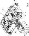
Figur 3 ist ein zum Ausführungsbeispiel nachFigur 2 alternatives Einschubteil beim Einschieben in den Raumbereich gezeigt, wobei vom Einschubteil ein zweites Energiespeichermodul 31 aufgenommen ist. - In
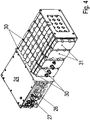
Figur 4 ist das Einschubteil mit zweitem Energiespeichermodul 31 ausFigur 4 näher dargestellt. - In der
Figur 5 ist ein Bereich einer Schrägansicht auf das zweite Energiespeichermodul 31 näher dargestellt. - In der
Figur 6 ist das Einschubteil mit erstem Energiespeichermodul 21 ausFigur 2 in einer anderen Blickrichtung näher dargestellt. - In der
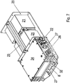
Figur 7 ist das Einschubteil mit erstem Energiespeichermodul 21 ausFigur 2 in einer weiteren Blickrichtung näher dargestellt. - In
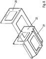
Figur 8 ist die Grundplatte 27 mit Seitenwänden 20 und 22 in Schrägansicht näher dargestellt. - Wie in den Figuren gezeigt, weist das Fahrzeug an seinem Gestell drehbar gelagerte Räder 2 angeordnet, insbesondere zur Ableitung der wesentlichen Gewichtskraft des Fahrzeugs In die Verfahrfläche. Vorzugsweise sind die Räder 2 als Lenkrollen ausgeführt. Das Fahrzeug weist eine drehbar angeordnete Lenkeinheit auf, deren Räder lenkbar und antreibbar sind von einem Elektromotor.
- Am Gestell ist einen Steuerung 7 angeordnet, welche einen Wechselrichter zur Speisung des Elektromotors ansteuert. Auf diese Weise ist die Drehzahl des Elektromotors steuerbar. Außerdem steuert die Steuerung 7 über einen weiteren Elektromotor den Lenkwinkel der Lenkeinheit. Die Steuerung 7 steuert also das Fahrzeug entlang einer Bahnkurve auf der Verfahrfläche.
- Das Fahrzeug weist einen Energiespeicher 5, insbesondere Batterie, auf, der zur Versorgung der Steuerung 7 dient.
- An der Unterseite des Gestells des Fahrzeugs ist eine Sekundärwicklung angeordnet, welche induktiv mit einem an der Verfahrfläche langgestreckt verlegten Primärleiter koppelbar. Dabei wird der Primärleiter mit einem Wechselstrom beaufschlagt, wobei die Frequenz des Wechselstroms zwischen 10 kHz und 1 MHz beträgt. Somit ist eine induktive Versorgung der elektrischen Verbraucher Des Fahrzeugs ermöglicht, solange das Fahrzeug derart nahe am Primärleiter positioniert ist, dass die induktive Kopplung zwischen dem an der Verfahrfläche angeordneten Primärleiter und der am Fahrzeug angeordneten Sekundärwicklung ausreichend stark ist.
- Wenn jedoch das Fahrzeug abweicht von einer Bahnkurve, welche dem Primärleiter folgt, fällt die induktive Versorgung aus. In diesem Fall wird dann die Steuerung 7 vom Energiespeicher 5 versorgt. Allerdings ist die Energiemenge des Energiespeichers 5 nicht ausreichend, um die Steuerung 7 und zusätzlich den Elektromotor lange Zeit zu speisen.
- Abhängig von der Logistikanlage oder Produktionsanlage, in welcher das Fahrzeug eingesetzt wird, ist ein weiterer Energiespeicher mittels eines in den Raumbereich einschiebbaren Einschubteils vorsehbar.
- Hierzu ist das Einschubteil mit einem jeweiligen Energiespeichermodul (21, 31) ausgestattet.
- Ein erstes Energiespeichermodul 21 besteht beispielsweise aus als Batterieen oder Akkumulatoren ausgeführten Modulen.
- Ein zweites, alternativ zum erste Energiespeichermodul 21 verwendbares Energiespeichermodul 31 besteht beispielsweise aus Modulen, die jeweils aus einem Doppelschichtkondensator und/oder Ultracap ausgeführt sind.
- Auf der Grundplatte 27 des Einschubteils ist jeweils ein DC/DC-Wandler 24 angeordnet, welcher die vom Energiespeichermodul 21 oder 31 zur Verfügung gestellte Spannung in eine Zwischenkreisspannung umwandelt, beispielsweise eine Spannung zwischen 400 Volt und 500 Volt, aus welcher dann der den als Fahrantrieb eingesetzten Elektromotor speisenden Wechselrichter versorgbar ist. Der Wechselrichter weist drei Halbbrücken von steuerbaren Leistungshalbleiterschaltern auf, so dass der Wechselrichter ausgangsseitig eine Drehspannung dem Elektromotor zur Verfügung stellt, deren Frequenz und Amplitude durch die Steuerung 7 vorgegeben ist.
- Der DC/DC-Wandler 24 weist Kühlrippen 26 auf und ist auf der Grundplatte des Einschubteils 27 angeordnet, wobei die Kühlrippen 26 auf der dem Einschubteil 27 zugewandten Seite des DC/DC-Wandlers 24 angeordnet sind.
- Am Gestell des Fahrzeugs ist ein wannenförmiges Gehäuseteil 1 angeordnet, wobei die Wannenform eine Vertiefung bewirkt. Das Einschubteil, insbesondere die Grundplatte 27 des Einschubteils, wird auf dem Gehäuseteil 1 gleitend eingeschoben, wobei die wannenförmige Vertiefung sich in Einschubrichtung erstreckt und somit als Führung beim Einschieben dient.
- In Einschubrichtung vorne ist am Einschubteil, insbesondere an der Grundplatte 27 des Einschubteils, ein Hybridsteckverbinderteil angeordnet, welches in ein am Gestell des Fahrzeugs angeordnetes entsprechendes Gegensteckverbinderteil eingesteckt wird. Da die Bewegung geführt ausgeführt wird, ist auch beim Einstecken des Steckverbinderteils in das Gegensteckverbinderteil ein Verkanten vermeidbar.
- Das jeweilige Energiespeichermodul 21 oder 31 ist elektrisch verbunden mit einem der beiden Gleichspannungsanschlüsse des DC/DC-Wandlers 24. Der andere Gleichspannungsanschluss ist an die Kontakte des Hybridsteckverbinderteils geführt.
- Auf diese Weise ist ein schnelles Verbinden ausführbar und es ist ein Einschubteil schnell und einfach austauschbar - beispielsweise bei Wartung oder bei Austausch eines
- Einschubteils mit leerem Energiespeichermodul (21, 31) gegen ein Einschubteil mit einem voll geladenen Energiespeichermodul (21, 31).
- Wie in
Figur 2 gezeigt, werden das erste Energiespeichermodul 21 von einer Halteschiene 23, die zwei voneinander beabstandete Seitenwände 20 und 22 miteinander verbindet, begrenzt und somit mechanisch stabil genug fixiert. Dabei ist das erste Energiespeichermodul 21 an der Halteschiene 23 hängend befestigbar, so dass ein Luftraum zwischen Grundplatte 27 und erstem Energiespeichermodul 21 vorhanden ist. Auf diese Weise ist das erste Energiespeichermodul 21 thermisch entkoppelt von der Grundplatte 27 und somit auch von dem über die Kühlrippen 26 in die Grundplatte 27 eingetragenen Wärmestrom des DC/DC-Wandlers 24. - Wie in
Figur 3 gezeigt, wird das zweiten Energiespeichermodul 31 mittels durch das Gehäuse des zweiten Energiespeichermoduls 31 durchgehender Schrauben 30 an einer Seitenwand 22 und/oder 20 befestigt. Somit ist eine hängende Befestigung ermöglicht und wiederum eine Beabstandung zwischen der Grundplatte 27 des Einschubteils und dem zweiten Energiespeichermodul 31 vorsehbar. Auf diese Weise ist das erste Energiespeichermodul 31 thermisch entkoppelt von der Grundplatte 27 und somit auch von dem über die Kühlrippen 26 in die Grundplatte 27 eingetragenen Wärmestrom des DC/DC-Wandlers 24. - Wie in den
Figuren 2 und3 gezeigt, ist an der der Umgebung zugewandten Endbereich der Grundplatte 27 ein Griff angeordnet, der zusammen mit einer Ausnehmung 32 der Grundplatte als Tragegriff fungieren kann. Beim separaten Tragen des Einschubteils greifen also die Finger des Tragenden durch die Ausnehmung 32. - Das Gehäuseteil 1 weist durchgehende Schlitze 8, insbesondere voneinander in Einschubrichtung regelmäßig beabstandete, sich quer zur Einschubrichtung in der Grundplatte des Einschubteils erstreckende, durchgehende Schlitze 8, auf. Somit ist ein Kühlluftstrom durch das Gehäuseteil 1 hindurch ermöglicht.
- Nach dem Einschieben liegt die Grundplatte 27 auf dem Gehäuseteil 1 auf, so dass die Ausnehmung 32 über dem von den Schlitzen 8 überdeckten Bereich angeordnet ist.
- Auf diese Weise tritt der durch die Schlitze 8 hindurchtretende Kühlluftstrom auch durch die Ausnehmung hindurch und gelangt somit auch direkt an die Kühlrippen 26 des DC/DC-Wandlers.
- Die Grundplatte 27 weist auch durchgehende Löcher 25 auf, die nach dem Einschieben in Flucht liegen mit entsprechenden durch das Gehäuseteil 1 durchgehenden Löchern, so dass Halteschrauben zur Fixierung der Grundplatte durch die Löcher hindurchführbar sind und mittels Muttern befestigbar sind. Nach dem Einschieben wird der Raumbereich gegen die Umgebung mit einem ans Gestell anzuschraubenden Gehäuseblechteil abgedeckt und geschützt.
- Erfindungsgemäß ist also durch das Einschubteil die Ladekapazität des Fahrzeugs erhöhbar. Mittels des ersten Energiespeichermoduls 21 ist eine große zusätzliche Energiemenge bereitstellbar, wobei der Spitzenstrom beim Laden und beim Entladen begrenzt ist. Durch das zweite Energiespeichermodul 31 sind sehr viel höhere Spitzenströme ermöglicht, wobei die speicherbare Energiemenge etwas geringer als beim ersten Energiespeichermodul 21 ist. Somit ist im letztgenannten Fall bei induktiver Versorgung des Fahrzeugs das zweite Energiespeichermodul 31 schnell aufladbar und somit kleine Abweichungen der Bahnkurve des Fahrzeugs vom Primärleiter abpufferbar.
- Mittels des ersten Energiespeichermoduls 21 sind große Abweichungen vom Primärleiter erlaubt. Allerdings muss das erste Energiespeichermodul 21 zunächst genügend aufgeladen sein.
- Die Steuerung 7 umfasst ein entsprechendes Energiemanagementsystem und verwendet den DC/DC-Wandler 24 als Steuerelement zum Steuern des Energieflusses.
- Am Fahrzeug sind auch Sensoren 4 vorgesehen, welche Hindernisse rechtzeitig erkennen und somit ein Anhalten oder Umfahren ermöglichen. Außerdem ist auch ein Notaus-Schalter 3 von außen zugänglich vorhanden, so dass ein Abschalten des Fahrzeugs ermöglicht ist.
- Die Grundplatte 27 ist im der Umgebung zugewandten Bereich der Wannenform entsprechend geformt.
- Das Fahrzeug ist als fahrerloses Transportsystem verwendbar, insbesondere auch als automatisch gesteuertes Fahrzeug. Auf der Oberseite ist eine in den Figuren nicht gezeigte Deckplatte am Gestell des Fahrzeugs befestigt und somit eine zu transportierende Last aufnehmbar. In Weiterbildung ist die Deckplatte über einen Linearaktor höhenveränderlich angeordnet, so dass die Last in verschiedenen Höhen aufnehmbar und transportierbar ist. In Weiterbildung ist auf der Deckplatte sogar ein Werkzeug zur Bearbeitung der aufgenommenen Last, insbesondere Werkstück, ermöglicht.
-
- 1
- wannenförmiges Gehäuseteil
- 2
- Rad
- 3
- Notaus-Schalter
- 4
- Sensor
- 5
- Energiespeicher, insbesondere Batterie
- 6
- AC/DC-Wandler, insbesondere Anpasssteller
- 7
- Steuerung
- 8
- durchgehende Schlitze, insbesondere voneinander in Einschubrichtung regelmäßig beabstandete, sich quer zur Einschubrichtung in der Grundplatte des Einschubteils erstreckende, durchgehende Schlitze
- 20
- Seitenwand des Einschubteils
- 21
- erstes Energiespeichermodul
- 22
- Seitenwand des Einschubteils
- 23
- Halteschiene
- 24
- DC/DC-Wandler
- 25
- Löcher
- 26
- Kühlkörper
- 27
- Grundplatte des Einschubteils
- 28
- Griff
- 30
- Halteschrauben
- 31
- zweites Energiespeichermodul, insbesondere Ultracap
- 32
- Ausnehmung
Claims (10)
- Fahrzeug, insbesondere Logistikfahrzeug,aufweisend ein Gestell und ein daran befestigtes Gehäuseteil (1),wobei ein Einschubteil auf dem Gehäuseteil (1) in einen Raumbereich des Fahrzeugs einschiebbar ist,wobei auf dem Einschubteil ein erstes oder zweites Energiespeichermodul (21, 31) angeordnet ist und ein mit dem Energiespeichermodul (21, 31) elektrisch verbundener DC/DC-Wandler (24),insbesondere wobei das erste Energiespeichermodul (21) insbesondere in seiner Wirkweise unterschiedlich ist zu dem zweiten Energiespeichermodul (31)und/oder wobeidas erste Energiespeichermodul (21) eine Batterie oder ein Akkumulator ist und das zweite Energiespeichermodul (31) ein Doppelschichtkondensator und/oder ein Ultracap-Kondensator ist,wobeizur Führung und/oder Zentrierung des Einschubteils das Gehäuseteil (1) wannenförmig ausgeformt ist,wobei beim Einschieben des Einschubteils die Wannenform als Führung des Einschubteils fungiert,wobei das Gehäuseteil (1) durchgehende Schlitze aufweist, insbesondere in Einschubrichtung regelmäßig voneinander beabstandete Schlitze,dadurch gekennzeichnet, dass der DC/DC-Wandler (24) auf seiner der Grundplatte (27) zugewandten Seite Kühlrippen aufweist,wobei das Einschubteil eine auf dem wannenförmigen Gehäuseteil (1) gleitend einschiebbare Grundplatte (27) aufweist, welche eine Ausnehmung (32) aufweist,wobei die senkrechte Projektion der Ausnehmung (32) in die Verfahrfläche des Fahrzeugs überlappt mit der senkrechten Projektion der Schlitze in die Verfahrfläche, so dass durch die Schlitze durchtretende Kühlluft durch dieAusnehmung (32) zu den Kühlrippen des DC/DC-Wandlers (24) geleitet wird,wobei an der Grundplatte (27) ein Steckverbinderteil angeordnet ist, welches beim Einschieben des Einschubteils in Steckkontakt mit einem entsprechenden, mit dem Gestell des Fahrzeugs verbundenen Gegensteckverbinderteil gebracht wird, so dass der DC/DC-Wandler (24) elektrisch verbunden ist mit einem Zwischenkreis, aus dem ein Wechselrichter versorgbar ist, welcher einen Elektromotor insbesondere zum Antreiben eines Rades des Fahrzeugs speist.
- Fahrzeug nach Anspruch 1,dadurch gekennzeichnet, dassdie Vertiefung der Wanne sich in Einschubrichtung erstreckt.
- Fahrzeug nach mindestens einem der vorangegangenen Ansprüche,dadurch gekennzeichnet, dassdas Steckverbinderteil ein Hybridsteckverbinderteil ist,wobei erste Kontakte mit einem Gleichspannungsanschluss des DC/DC-Wandlers (24) verbunden ist und zweite Kontakte Signale eines Datenbusses führen, welcher zwischen einer Steuerung des Fahrzeugs und dem DC/DC-Wandler (24) vorgesehen ist.
- Fahrzeug nach mindestens einem der vorangegangenen Ansprüche,dadurch gekennzeichnet, dassan der Unterseite des Fahrzeugs eine Sekundärwicklung angeordnet ist, insbesondere an welche Energie von einem in der Verfahrfläche verlegten Primärleiter übertragbar ist,wobei aus der Sekundärwicklung Energie dem Zwischenkreis zuführbar ist, insbesondere über einen AC/DC-Wandler (6),und/oder dassam Gestell des Fahrzeugs ein Energiespeicher, insbesondere Akkumulator oder Batterie, angeordnet ist, aus welchem zumindest die Steuerung des Fahrzeugs versorgbar ist.
- Fahrzeug nach mindestens einem der vorangegangenen Ansprüche,dadurch gekennzeichnet, dassan der Grundplatte (27) zwei Seitenwände des Einschubteils befestigt sind,an welchen das zweite Energiespeichermodul (31) angeschraubt ist mit einer durch das Gehäuse des zweiten Energiespeichermoduls (31) durchgehenden Schraube, insbesondere so dass zwischen zweitem Energiespeichermodul (31) und Grundplatte (27) ein Abstand vorhanden ist,oder zwischen welchen eine Halteschiene (23) befestigt ist, an welcher das erste Energiespeichermodul (21) angehängt gehalten ist, insbesondere so dass zwischen erstem Energiespeichermodul (21) und Grundplatte (27) ein Abstand vorhanden ist.
- Fahrzeug nach mindestens einem der vorangegangenen Ansprüche,dadurch gekennzeichnet, dassan der Grundplatte (27) ein Griff (28) ausgeformt istund/oder dassdurchgehende Löcher zur Fixierung des Einschubteils angeordnet sind am Gehäuseteil (1) mittels Schrauben.
- Fahrzeug nach mindestens einem der vorangegangenen Ansprüche,dadurch gekennzeichnet, dassdie das erste oder zweite Energiespeichermodul (21, 31) haltende Seitenwand mit der Grundplatte (27) verbunden ist.
- Fahrzeug nach mindestens einem der vorangegangenen Ansprüche,dadurch gekennzeichnet, dassder Raumbereich zumindest auch vom Gestell, von der Grundplatte (27), von einem mit dem Gestell des Fahrzeugs verbundenen Gehäuseblechteil und einer Deckplatte begrenzt ist,insbesondere wobei der Raumbereich zur Umgebung hin vom Gehäuseblechteil abgedeckt ist,insbesondere wobei das Gehäuseblechteil mit dem Gestell schraubverbunden ist.
- Fahrzeug nach mindestens einem der vorangegangenen Ansprüche,dadurch gekennzeichnet, dassder Sekundärwicklung eine Kapazität in Reihe und/oder parallel zugeschaltet ist, so dass die Resonanzfrequenz des so gebildeten Schwingkreises der Frequenz des in den Primärleiter eingeprägten Wechselstromes gleicht.
- Verfahren zum Betreiben eines Fahrzeugs nach mindestens einem der vorangegangenen Ansprüche,dadurch gekennzeichnet, dassnach dem Einschieben des Einschubteils und elektrischen Verbinden des DC/DC-Wandlers (24) mit dem Zwischenkreis des Fahrzeugs der DC/DC-Wandler (24) automatisch erkannt wird und als Busteilnehmer eines Datenbusses des Fahrzeugs betrieben wird, insbesondere zum Steuern des Energieflusses gemäß Vorgabe durch ein Energiemanagementsystem.
Applications Claiming Priority (2)
| Application Number | Priority Date | Filing Date | Title |
|---|---|---|---|
| DE102016014627 | 2016-12-09 | ||
| PCT/EP2017/025347 WO2018103892A1 (de) | 2016-12-09 | 2017-11-27 | Fahrzeug, insbesondere logistikfahrzeug |
Publications (2)
| Publication Number | Publication Date |
|---|---|
| EP3551492A1 EP3551492A1 (de) | 2019-10-16 |
| EP3551492B1 true EP3551492B1 (de) | 2022-01-05 |
Family
ID=60765575
Family Applications (1)
| Application Number | Title | Priority Date | Filing Date |
|---|---|---|---|
| EP17817654.1A Active EP3551492B1 (de) | 2016-12-09 | 2017-11-27 | Fahrzeug und verfahren zum betreiben des fahrzeuges |
Country Status (6)
| Country | Link |
|---|---|
| US (2) | US11491889B2 (de) |
| EP (1) | EP3551492B1 (de) |
| CN (1) | CN110049894B (de) |
| DE (1) | DE102017010924A1 (de) |
| ES (1) | ES2905762T3 (de) |
| WO (1) | WO2018103892A1 (de) |
Families Citing this family (7)
| Publication number | Priority date | Publication date | Assignee | Title |
|---|---|---|---|---|
| EP3551492B1 (de) * | 2016-12-09 | 2022-01-05 | Sew-Eurodrive GmbH & Co. KG | Fahrzeug und verfahren zum betreiben des fahrzeuges |
| JP7066529B2 (ja) * | 2018-05-31 | 2022-05-13 | 矢崎総業株式会社 | Dc/dc変換ユニット |
| JP7094780B2 (ja) * | 2018-05-31 | 2022-07-04 | 矢崎総業株式会社 | Dc/dc変換ユニット |
| CN110422076A (zh) * | 2019-08-08 | 2019-11-08 | 东莞市云晟电子科技有限公司 | 一种不断电自动更换电池的装置 |
| EP4077023A1 (de) | 2019-12-18 | 2022-10-26 | Sew-Eurodrive GmbH & Co. KG | Verfahren zum betreiben eines elektrischen fahrzeuges und elektrisches fahrzeug |
| US12473148B2 (en) | 2020-05-05 | 2025-11-18 | Sew-Eurodrive Gmbh & Co. Kg | Electric vehicle and method for operating an electric vehicle |
| DE102021111504A1 (de) | 2021-05-04 | 2022-11-10 | Audi Aktiengesellschaft | Batterieeinheit für ein Kraftfahrzeug, Kraftfahrzeug und Verfahren zum Steuern einer Batterieeinheit |
Family Cites Families (18)
| Publication number | Priority date | Publication date | Assignee | Title |
|---|---|---|---|---|
| DE19641254C2 (de) | 1996-10-07 | 1999-02-18 | Daimler Benz Ag | Wechselvorrichtung für Energie-Versorgungs-Einheiten von Straßenfahrzeugen |
| US20010052433A1 (en) | 2000-04-14 | 2001-12-20 | Harris Donald B. | Hybrid power supply module |
| US20030070850A1 (en) | 2001-02-16 | 2003-04-17 | Cellex Power Products, Inc. | Hybrid power supply apparatus for battery replacement applications |
| US6649290B2 (en) * | 2001-05-11 | 2003-11-18 | Cellex Power Products, Inc. | Fuel cell thermal management system and method |
| JP2004026008A (ja) * | 2002-06-25 | 2004-01-29 | Honda Motor Co Ltd | 燃料電池電気自動車 |
| DE102005042940A1 (de) * | 2005-09-09 | 2007-03-22 | Still Gmbh | Flurförderzeug mit einer Brennstoffzelleneinheit und einer Batterie |
| JP4618814B2 (ja) * | 2007-12-07 | 2011-01-26 | 本田技研工業株式会社 | 車両用電源装置 |
| US8006793B2 (en) | 2008-09-19 | 2011-08-30 | Better Place GmbH | Electric vehicle battery system |
| DE102009014386A1 (de) | 2009-03-26 | 2010-09-30 | Volkswagen Ag | Energiespeicher und Steuerung zur Energieversorgung eines Traktionsnetzes eines Elektrofahrzeugs |
| DE102010021705B4 (de) * | 2010-05-27 | 2017-10-19 | Sew-Eurodrive Gmbh & Co Kg | Verfahren zum Transportieren eines Objektes, Fahrzeug, Anlage |
| JP5658592B2 (ja) * | 2011-02-21 | 2015-01-28 | 国立大学法人埼玉大学 | 移動体用非接触給電装置 |
| US8779622B2 (en) | 2011-06-30 | 2014-07-15 | GM Global Technology Operations LLC | Customizable energy system and vehicle |
| WO2013016545A2 (en) | 2011-07-26 | 2013-01-31 | Gogoro, Inc. | Apparatus, method and article for providing vehicle diagnostic data |
| DE102011115570B4 (de) | 2011-10-10 | 2016-11-17 | MULAG FAHRZEUGWERK Heinz Wössner GmbH & Co. KG | Schlepper mit unterschiedlicher Energie-Versorgungseinheit |
| GB201121938D0 (en) * | 2011-12-21 | 2012-02-01 | Dames Andrew N | Supply of grid power to moving vehicles |
| FR3010960B1 (fr) * | 2013-09-23 | 2017-01-27 | Cassidian Sas | Procede et systeme de gestion de l'energie a bord d'un vehicule |
| DE102014006960A1 (de) | 2014-05-13 | 2015-11-19 | Thomas Reiner Lang | Selbstfahrendes Energieversorgungsgerät; Energie-Servant |
| EP3551492B1 (de) * | 2016-12-09 | 2022-01-05 | Sew-Eurodrive GmbH & Co. KG | Fahrzeug und verfahren zum betreiben des fahrzeuges |
-
2017
- 2017-11-27 EP EP17817654.1A patent/EP3551492B1/de active Active
- 2017-11-27 US US16/468,216 patent/US11491889B2/en active Active
- 2017-11-27 WO PCT/EP2017/025347 patent/WO2018103892A1/de not_active Ceased
- 2017-11-27 CN CN201780075090.2A patent/CN110049894B/zh active Active
- 2017-11-27 ES ES17817654T patent/ES2905762T3/es active Active
- 2017-11-27 DE DE102017010924.9A patent/DE102017010924A1/de active Pending
-
2022
- 2022-11-01 US US17/978,620 patent/US11718199B2/en active Active
Also Published As
| Publication number | Publication date |
|---|---|
| US11491889B2 (en) | 2022-11-08 |
| US20190389328A1 (en) | 2019-12-26 |
| WO2018103892A1 (de) | 2018-06-14 |
| ES2905762T3 (es) | 2022-04-12 |
| CN110049894A (zh) | 2019-07-23 |
| US20230047566A1 (en) | 2023-02-16 |
| US11718199B2 (en) | 2023-08-08 |
| CN110049894B (zh) | 2023-04-04 |
| DE102017010924A1 (de) | 2018-06-14 |
| EP3551492A1 (de) | 2019-10-16 |
Similar Documents
| Publication | Publication Date | Title |
|---|---|---|
| DE102017010924A1 (de) | Fahrzeug, insbesondere Logistikfahrzeug | |
| DE102011110196B4 (de) | Mobilteil | |
| EP3468829B1 (de) | Verfahren zum betreiben eines elektrischen fahrzeuges und elektrisches fahrzeug | |
| EP2361855B1 (de) | Regalbedienvorrichtung | |
| DE202018003439U1 (de) | System zum Betrieb und Wechsel von Akkumulatoren in elektrisch angetriebenen Kraftfahrzeugen | |
| EP3704000B1 (de) | Verfahren und fahrzeug zum fördern eines elektrisch angetriebenen kraftfahrzeugs während dessen montage | |
| EP1749341B1 (de) | Regallagersystem mit energierückkopplung | |
| EP3700066B1 (de) | Förderanlage zum fördern von stückgütern mit verbessertem elektrischem anschlusssystem | |
| EP1763449B1 (de) | Spurgeführtes transportsystem | |
| WO2012010230A1 (de) | Elektrobeladungssystem | |
| EP1644274B1 (de) | Spurgeführtes transportsystem | |
| EP1905142B1 (de) | System zur berührungslosen energieübertragung und verfahren zum betreiben eines solchen systems | |
| DE102010021706B4 (de) | Fahrzeug, Anlage und Verfahren zum Betreiben einer Anlage | |
| DE102012022479A1 (de) | Fahrzeug, System und Verfahren zum Betreiben eines Systems | |
| EP3697641B1 (de) | System und verfahren zur energieübertragung an ein als fahrzeug ausgeführtes mobilteil mit energiespeicher und sekundärwicklung | |
| DE102010021866B4 (de) | Vorrichtung zur berührungslosen Energieübertragung und Verfahren zum Betreiben | |
| EP3543200B1 (de) | Verfahren zur steuerung eines regalbediengeräts | |
| DE102013020525A1 (de) | Ladesystem | |
| EP3976417B1 (de) | Antriebssystem und verfahren zum betreiben eines antriebssystems | |
| DE102010021864B4 (de) | Lagervorrichtung und Verfahren zum Betreiben einer Lagervorrichtung | |
| WO2025261737A1 (de) | Förderanlage, insbesondere bauaufzug | |
| DE102011009933B4 (de) | Elektrofahrzeug und Verfahren zum Betreiben eines Elektrofahrzeugs | |
| WO2013104408A1 (de) | Ladeeinrichtung | |
| DE102024126283A1 (de) | Adaptereinrichtung zum Laden eines elektrischen Energiespeichers eines Fahrzeugs | |
| EP3323186B1 (de) | Anordnung zur induktiven übertragung elektrischer energie von einem stationär angeordneten primärleiter an eine relativ dazu bewegbare vorrichtung und verfahren zum betreiben der anordnung |
Legal Events
| Date | Code | Title | Description |
|---|---|---|---|
| STAA | Information on the status of an ep patent application or granted ep patent |
Free format text: STATUS: UNKNOWN |
|
| STAA | Information on the status of an ep patent application or granted ep patent |
Free format text: STATUS: THE INTERNATIONAL PUBLICATION HAS BEEN MADE |
|
| PUAI | Public reference made under article 153(3) epc to a published international application that has entered the european phase |
Free format text: ORIGINAL CODE: 0009012 |
|
| STAA | Information on the status of an ep patent application or granted ep patent |
Free format text: STATUS: REQUEST FOR EXAMINATION WAS MADE |
|
| 17P | Request for examination filed |
Effective date: 20190709 |
|
| AK | Designated contracting states |
Kind code of ref document: A1 Designated state(s): AL AT BE BG CH CY CZ DE DK EE ES FI FR GB GR HR HU IE IS IT LI LT LU LV MC MK MT NL NO PL PT RO RS SE SI SK SM TR |
|
| AX | Request for extension of the european patent |
Extension state: BA ME |
|
| DAV | Request for validation of the european patent (deleted) | ||
| DAX | Request for extension of the european patent (deleted) | ||
| REG | Reference to a national code |
Ref country code: DE Ref legal event code: R079 Ref document number: 502017012422 Country of ref document: DE Free format text: PREVIOUS MAIN CLASS: B60L0011000000 Ipc: B60L0050400000 |
|
| RIC1 | Information provided on ipc code assigned before grant |
Ipc: B60L 50/40 20190101AFI20210622BHEP Ipc: B60L 53/80 20190101ALI20210622BHEP Ipc: B60L 58/20 20190101ALI20210622BHEP |
|
| GRAP | Despatch of communication of intention to grant a patent |
Free format text: ORIGINAL CODE: EPIDOSNIGR1 |
|
| STAA | Information on the status of an ep patent application or granted ep patent |
Free format text: STATUS: GRANT OF PATENT IS INTENDED |
|
| INTG | Intention to grant announced |
Effective date: 20210803 |
|
| GRAS | Grant fee paid |
Free format text: ORIGINAL CODE: EPIDOSNIGR3 |
|
| GRAA | (expected) grant |
Free format text: ORIGINAL CODE: 0009210 |
|
| STAA | Information on the status of an ep patent application or granted ep patent |
Free format text: STATUS: THE PATENT HAS BEEN GRANTED |
|
| AK | Designated contracting states |
Kind code of ref document: B1 Designated state(s): AL AT BE BG CH CY CZ DE DK EE ES FI FR GB GR HR HU IE IS IT LI LT LU LV MC MK MT NL NO PL PT RO RS SE SI SK SM TR |
|
| REG | Reference to a national code |
Ref country code: GB Ref legal event code: FG4D Free format text: NOT ENGLISH |
|
| REG | Reference to a national code |
Ref country code: CH Ref legal event code: EP |
|
| REG | Reference to a national code |
Ref country code: AT Ref legal event code: REF Ref document number: 1460234 Country of ref document: AT Kind code of ref document: T Effective date: 20220115 |
|
| REG | Reference to a national code |
Ref country code: DE Ref legal event code: R096 Ref document number: 502017012422 Country of ref document: DE |
|
| REG | Reference to a national code |
Ref country code: IE Ref legal event code: FG4D Free format text: LANGUAGE OF EP DOCUMENT: GERMAN |
|
| REG | Reference to a national code |
Ref country code: ES Ref legal event code: FG2A Ref document number: 2905762 Country of ref document: ES Kind code of ref document: T3 Effective date: 20220412 |
|
| REG | Reference to a national code |
Ref country code: LT Ref legal event code: MG9D |
|
| REG | Reference to a national code |
Ref country code: NL Ref legal event code: MP Effective date: 20220105 |
|
| PG25 | Lapsed in a contracting state [announced via postgrant information from national office to epo] |
Ref country code: NL Free format text: LAPSE BECAUSE OF FAILURE TO SUBMIT A TRANSLATION OF THE DESCRIPTION OR TO PAY THE FEE WITHIN THE PRESCRIBED TIME-LIMIT Effective date: 20220105 |
|
| PG25 | Lapsed in a contracting state [announced via postgrant information from national office to epo] |
Ref country code: SE Free format text: LAPSE BECAUSE OF FAILURE TO SUBMIT A TRANSLATION OF THE DESCRIPTION OR TO PAY THE FEE WITHIN THE PRESCRIBED TIME-LIMIT Effective date: 20220105 Ref country code: RS Free format text: LAPSE BECAUSE OF FAILURE TO SUBMIT A TRANSLATION OF THE DESCRIPTION OR TO PAY THE FEE WITHIN THE PRESCRIBED TIME-LIMIT Effective date: 20220105 Ref country code: PT Free format text: LAPSE BECAUSE OF FAILURE TO SUBMIT A TRANSLATION OF THE DESCRIPTION OR TO PAY THE FEE WITHIN THE PRESCRIBED TIME-LIMIT Effective date: 20220505 Ref country code: NO Free format text: LAPSE BECAUSE OF FAILURE TO SUBMIT A TRANSLATION OF THE DESCRIPTION OR TO PAY THE FEE WITHIN THE PRESCRIBED TIME-LIMIT Effective date: 20220405 Ref country code: LT Free format text: LAPSE BECAUSE OF FAILURE TO SUBMIT A TRANSLATION OF THE DESCRIPTION OR TO PAY THE FEE WITHIN THE PRESCRIBED TIME-LIMIT Effective date: 20220105 Ref country code: HR Free format text: LAPSE BECAUSE OF FAILURE TO SUBMIT A TRANSLATION OF THE DESCRIPTION OR TO PAY THE FEE WITHIN THE PRESCRIBED TIME-LIMIT Effective date: 20220105 Ref country code: BG Free format text: LAPSE BECAUSE OF FAILURE TO SUBMIT A TRANSLATION OF THE DESCRIPTION OR TO PAY THE FEE WITHIN THE PRESCRIBED TIME-LIMIT Effective date: 20220405 |
|
| PG25 | Lapsed in a contracting state [announced via postgrant information from national office to epo] |
Ref country code: PL Free format text: LAPSE BECAUSE OF FAILURE TO SUBMIT A TRANSLATION OF THE DESCRIPTION OR TO PAY THE FEE WITHIN THE PRESCRIBED TIME-LIMIT Effective date: 20220105 Ref country code: LV Free format text: LAPSE BECAUSE OF FAILURE TO SUBMIT A TRANSLATION OF THE DESCRIPTION OR TO PAY THE FEE WITHIN THE PRESCRIBED TIME-LIMIT Effective date: 20220105 Ref country code: GR Free format text: LAPSE BECAUSE OF FAILURE TO SUBMIT A TRANSLATION OF THE DESCRIPTION OR TO PAY THE FEE WITHIN THE PRESCRIBED TIME-LIMIT Effective date: 20220406 Ref country code: FI Free format text: LAPSE BECAUSE OF FAILURE TO SUBMIT A TRANSLATION OF THE DESCRIPTION OR TO PAY THE FEE WITHIN THE PRESCRIBED TIME-LIMIT Effective date: 20220105 |
|
| PG25 | Lapsed in a contracting state [announced via postgrant information from national office to epo] |
Ref country code: IS Free format text: LAPSE BECAUSE OF FAILURE TO SUBMIT A TRANSLATION OF THE DESCRIPTION OR TO PAY THE FEE WITHIN THE PRESCRIBED TIME-LIMIT Effective date: 20220505 |
|
| REG | Reference to a national code |
Ref country code: DE Ref legal event code: R097 Ref document number: 502017012422 Country of ref document: DE |
|
| PG25 | Lapsed in a contracting state [announced via postgrant information from national office to epo] |
Ref country code: SM Free format text: LAPSE BECAUSE OF FAILURE TO SUBMIT A TRANSLATION OF THE DESCRIPTION OR TO PAY THE FEE WITHIN THE PRESCRIBED TIME-LIMIT Effective date: 20220105 Ref country code: SK Free format text: LAPSE BECAUSE OF FAILURE TO SUBMIT A TRANSLATION OF THE DESCRIPTION OR TO PAY THE FEE WITHIN THE PRESCRIBED TIME-LIMIT Effective date: 20220105 Ref country code: RO Free format text: LAPSE BECAUSE OF FAILURE TO SUBMIT A TRANSLATION OF THE DESCRIPTION OR TO PAY THE FEE WITHIN THE PRESCRIBED TIME-LIMIT Effective date: 20220105 Ref country code: EE Free format text: LAPSE BECAUSE OF FAILURE TO SUBMIT A TRANSLATION OF THE DESCRIPTION OR TO PAY THE FEE WITHIN THE PRESCRIBED TIME-LIMIT Effective date: 20220105 Ref country code: DK Free format text: LAPSE BECAUSE OF FAILURE TO SUBMIT A TRANSLATION OF THE DESCRIPTION OR TO PAY THE FEE WITHIN THE PRESCRIBED TIME-LIMIT Effective date: 20220105 Ref country code: CZ Free format text: LAPSE BECAUSE OF FAILURE TO SUBMIT A TRANSLATION OF THE DESCRIPTION OR TO PAY THE FEE WITHIN THE PRESCRIBED TIME-LIMIT Effective date: 20220105 |
|
| PLBE | No opposition filed within time limit |
Free format text: ORIGINAL CODE: 0009261 |
|
| STAA | Information on the status of an ep patent application or granted ep patent |
Free format text: STATUS: NO OPPOSITION FILED WITHIN TIME LIMIT |
|
| PG25 | Lapsed in a contracting state [announced via postgrant information from national office to epo] |
Ref country code: AL Free format text: LAPSE BECAUSE OF FAILURE TO SUBMIT A TRANSLATION OF THE DESCRIPTION OR TO PAY THE FEE WITHIN THE PRESCRIBED TIME-LIMIT Effective date: 20220105 |
|
| 26N | No opposition filed |
Effective date: 20221006 |
|
| PG25 | Lapsed in a contracting state [announced via postgrant information from national office to epo] |
Ref country code: SI Free format text: LAPSE BECAUSE OF FAILURE TO SUBMIT A TRANSLATION OF THE DESCRIPTION OR TO PAY THE FEE WITHIN THE PRESCRIBED TIME-LIMIT Effective date: 20220105 |
|
| PG25 | Lapsed in a contracting state [announced via postgrant information from national office to epo] |
Ref country code: MC Free format text: LAPSE BECAUSE OF FAILURE TO SUBMIT A TRANSLATION OF THE DESCRIPTION OR TO PAY THE FEE WITHIN THE PRESCRIBED TIME-LIMIT Effective date: 20220105 |
|
| REG | Reference to a national code |
Ref country code: CH Ref legal event code: PL |
|
| GBPC | Gb: european patent ceased through non-payment of renewal fee |
Effective date: 20221127 |
|
| REG | Reference to a national code |
Ref country code: BE Ref legal event code: MM Effective date: 20221130 |
|
| PG25 | Lapsed in a contracting state [announced via postgrant information from national office to epo] |
Ref country code: LI Free format text: LAPSE BECAUSE OF NON-PAYMENT OF DUE FEES Effective date: 20221130 Ref country code: CH Free format text: LAPSE BECAUSE OF NON-PAYMENT OF DUE FEES Effective date: 20221130 |
|
| PG25 | Lapsed in a contracting state [announced via postgrant information from national office to epo] |
Ref country code: LU Free format text: LAPSE BECAUSE OF NON-PAYMENT OF DUE FEES Effective date: 20221127 |
|
| PG25 | Lapsed in a contracting state [announced via postgrant information from national office to epo] |
Ref country code: IE Free format text: LAPSE BECAUSE OF NON-PAYMENT OF DUE FEES Effective date: 20221127 Ref country code: GB Free format text: LAPSE BECAUSE OF NON-PAYMENT OF DUE FEES Effective date: 20221127 |
|
| PG25 | Lapsed in a contracting state [announced via postgrant information from national office to epo] |
Ref country code: BE Free format text: LAPSE BECAUSE OF NON-PAYMENT OF DUE FEES Effective date: 20221130 |
|
| REG | Reference to a national code |
Ref country code: AT Ref legal event code: MM01 Ref document number: 1460234 Country of ref document: AT Kind code of ref document: T Effective date: 20221127 |
|
| PG25 | Lapsed in a contracting state [announced via postgrant information from national office to epo] |
Ref country code: AT Free format text: LAPSE BECAUSE OF NON-PAYMENT OF DUE FEES Effective date: 20221127 |
|
| PG25 | Lapsed in a contracting state [announced via postgrant information from national office to epo] |
Ref country code: HU Free format text: LAPSE BECAUSE OF FAILURE TO SUBMIT A TRANSLATION OF THE DESCRIPTION OR TO PAY THE FEE WITHIN THE PRESCRIBED TIME-LIMIT; INVALID AB INITIO Effective date: 20171127 |
|
| PG25 | Lapsed in a contracting state [announced via postgrant information from national office to epo] |
Ref country code: CY Free format text: LAPSE BECAUSE OF FAILURE TO SUBMIT A TRANSLATION OF THE DESCRIPTION OR TO PAY THE FEE WITHIN THE PRESCRIBED TIME-LIMIT Effective date: 20220105 |
|
| PG25 | Lapsed in a contracting state [announced via postgrant information from national office to epo] |
Ref country code: MK Free format text: LAPSE BECAUSE OF FAILURE TO SUBMIT A TRANSLATION OF THE DESCRIPTION OR TO PAY THE FEE WITHIN THE PRESCRIBED TIME-LIMIT Effective date: 20220105 |
|
| PG25 | Lapsed in a contracting state [announced via postgrant information from national office to epo] |
Ref country code: TR Free format text: LAPSE BECAUSE OF FAILURE TO SUBMIT A TRANSLATION OF THE DESCRIPTION OR TO PAY THE FEE WITHIN THE PRESCRIBED TIME-LIMIT Effective date: 20220105 |
|
| PG25 | Lapsed in a contracting state [announced via postgrant information from national office to epo] |
Ref country code: MT Free format text: LAPSE BECAUSE OF FAILURE TO SUBMIT A TRANSLATION OF THE DESCRIPTION OR TO PAY THE FEE WITHIN THE PRESCRIBED TIME-LIMIT Effective date: 20220105 |
|
| PGFP | Annual fee paid to national office [announced via postgrant information from national office to epo] |
Ref country code: FR Payment date: 20250930 Year of fee payment: 9 |
|
| PGFP | Annual fee paid to national office [announced via postgrant information from national office to epo] |
Ref country code: DE Payment date: 20251130 Year of fee payment: 9 |
|
| PGFP | Annual fee paid to national office [announced via postgrant information from national office to epo] |
Ref country code: IT Payment date: 20251104 Year of fee payment: 9 |
|
| PGFP | Annual fee paid to national office [announced via postgrant information from national office to epo] |
Ref country code: ES Payment date: 20251201 Year of fee payment: 9 |