EP2509777B1 - Surrogate patch for composite repair process - Google Patents
Surrogate patch for composite repair process Download PDFInfo
- Publication number
- EP2509777B1 EP2509777B1 EP10779165.9A EP10779165A EP2509777B1 EP 2509777 B1 EP2509777 B1 EP 2509777B1 EP 10779165 A EP10779165 A EP 10779165A EP 2509777 B1 EP2509777 B1 EP 2509777B1
- Authority
- EP
- European Patent Office
- Prior art keywords
- surrogate patch
- patch body
- rework area
- surrogate
- moisture
- Prior art date
- Legal status (The legal status is an assumption and is not a legal conclusion. Google has not performed a legal analysis and makes no representation as to the accuracy of the status listed.)
- Active
Links
Images


Classifications
-
- B—PERFORMING OPERATIONS; TRANSPORTING
- B32—LAYERED PRODUCTS
- B32B—LAYERED PRODUCTS, i.e. PRODUCTS BUILT-UP OF STRATA OF FLAT OR NON-FLAT, e.g. CELLULAR OR HONEYCOMB, FORM
- B32B43/00—Operations specially adapted for layered products and not otherwise provided for, e.g. repairing; Apparatus therefor
-
- B—PERFORMING OPERATIONS; TRANSPORTING
- B29—WORKING OF PLASTICS; WORKING OF SUBSTANCES IN A PLASTIC STATE IN GENERAL
- B29C—SHAPING OR JOINING OF PLASTICS; SHAPING OF MATERIAL IN A PLASTIC STATE, NOT OTHERWISE PROVIDED FOR; AFTER-TREATMENT OF THE SHAPED PRODUCTS, e.g. REPAIRING
- B29C73/00—Repairing of articles made from plastics or substances in a plastic state, e.g. of articles shaped or produced by using techniques covered by this subclass or subclass B29D
- B29C73/04—Repairing of articles made from plastics or substances in a plastic state, e.g. of articles shaped or produced by using techniques covered by this subclass or subclass B29D using preformed elements
- B29C73/10—Repairing of articles made from plastics or substances in a plastic state, e.g. of articles shaped or produced by using techniques covered by this subclass or subclass B29D using preformed elements using patches sealing on the surface of the article
- B29C73/12—Apparatus therefor, e.g. for applying
-
- B—PERFORMING OPERATIONS; TRANSPORTING
- B29—WORKING OF PLASTICS; WORKING OF SUBSTANCES IN A PLASTIC STATE IN GENERAL
- B29C—SHAPING OR JOINING OF PLASTICS; SHAPING OF MATERIAL IN A PLASTIC STATE, NOT OTHERWISE PROVIDED FOR; AFTER-TREATMENT OF THE SHAPED PRODUCTS, e.g. REPAIRING
- B29C73/00—Repairing of articles made from plastics or substances in a plastic state, e.g. of articles shaped or produced by using techniques covered by this subclass or subclass B29D
- B29C73/16—Auto-repairing or self-sealing arrangements or agents
- B29C73/163—Sealing compositions or agents, e.g. combined with propellant agents
-
- B—PERFORMING OPERATIONS; TRANSPORTING
- B29—WORKING OF PLASTICS; WORKING OF SUBSTANCES IN A PLASTIC STATE IN GENERAL
- B29C—SHAPING OR JOINING OF PLASTICS; SHAPING OF MATERIAL IN A PLASTIC STATE, NOT OTHERWISE PROVIDED FOR; AFTER-TREATMENT OF THE SHAPED PRODUCTS, e.g. REPAIRING
- B29C73/00—Repairing of articles made from plastics or substances in a plastic state, e.g. of articles shaped or produced by using techniques covered by this subclass or subclass B29D
- B29C73/24—Apparatus or accessories not otherwise provided for
- B29C73/26—Apparatus or accessories not otherwise provided for for mechanical pretreatment
-
- B—PERFORMING OPERATIONS; TRANSPORTING
- B29—WORKING OF PLASTICS; WORKING OF SUBSTANCES IN A PLASTIC STATE IN GENERAL
- B29C—SHAPING OR JOINING OF PLASTICS; SHAPING OF MATERIAL IN A PLASTIC STATE, NOT OTHERWISE PROVIDED FOR; AFTER-TREATMENT OF THE SHAPED PRODUCTS, e.g. REPAIRING
- B29C73/00—Repairing of articles made from plastics or substances in a plastic state, e.g. of articles shaped or produced by using techniques covered by this subclass or subclass B29D
- B29C73/24—Apparatus or accessories not otherwise provided for
- B29C73/30—Apparatus or accessories not otherwise provided for for local pressing or local heating
- B29C73/34—Apparatus or accessories not otherwise provided for for local pressing or local heating for local heating
-
- G—PHYSICS
- G01—MEASURING; TESTING
- G01K—MEASURING TEMPERATURE; MEASURING QUANTITY OF HEAT; THERMALLY-SENSITIVE ELEMENTS NOT OTHERWISE PROVIDED FOR
- G01K13/00—Thermometers specially adapted for specific purposes
-
- G—PHYSICS
- G01—MEASURING; TESTING
- G01N—INVESTIGATING OR ANALYSING MATERIALS BY DETERMINING THEIR CHEMICAL OR PHYSICAL PROPERTIES
- G01N27/00—Investigating or analysing materials by the use of electric, electrochemical, or magnetic means
-
- G—PHYSICS
- G01—MEASURING; TESTING
- G01N—INVESTIGATING OR ANALYSING MATERIALS BY DETERMINING THEIR CHEMICAL OR PHYSICAL PROPERTIES
- G01N33/00—Investigating or analysing materials by specific methods not covered by groups G01N1/00 - G01N31/00
Definitions
- the present disclosure relates generally to structural repair and, more particularly, to operations performed in preparation for the repair of composite structures.
- Composite materials are used in ever increasing amounts in a wide variety of applications. For example, commercial aircraft are incorporating increasing amounts of composite materials into primary and secondary structure due to the favorable mechanical properties of composite materials. Such favorable properties may translate into a reduction in weight and an increase in payload capacity and fuel efficiency. In addition, composite materials may provide an extended service life for the aircraft as compared to aircraft formed of metallic construction.
- An inconsistency may comprise a crack, a delamination, a void, a dent, porosity or other inconsistencies in the composite structure.
- An inconsistency may require rework when the inconsistency falls outside of desired tolerances.
- the removal of the inconsistency may require the reworking of an area in the composite structure containing the inconsistency by removing a portion of the composite structure containing the inconsistency and replacing the removed material with a patch.
- the patch may be formed as a stack of plies of composite material of the same or different type from which the composite structure is formed.
- the stacking sequence and fiber orientation of the composite plies in the patch may correspond to the stacking sequence and fiber orientation of the plies that make up the composite structure.
- the patch After assembling the patch from the stack of plies, the patch is typically bonded to the rework area with adhesive installed at the bondline between the patch and the rework area.
- Heat and pressure are typically applied to the patch such as with a heating blanket and a vacuum bag.
- the heating blanket may be used to elevate the bondline to the appropriate adhesive curing temperature.
- the vacuum bag may be used to consolidate the patch.
- the bondline may be held within a relatively narrow temperature range for a predetermined period of time in order to fully cure the adhesive.
- the entire area of the bondline may be held within the temperature range without substantial variation across the bondline.
- a thermal survey may be required for the rework area.
- the thermal survey may be required to identify locations of non-uniform heating of the rework area by the heating blanket.
- Non-uniform heating may be caused by adjacent structure that may act as a heat sink drawing heat away from localized portions of the rework area resulting in differential heating of the bondline.
- the thermal survey may provide a means for identifying hot and cold spots in the rework area such that adjustments can be made by adding temporary insulation to the composite structure and/or by adjusting the heating from the heating blanket until the temperature is within the required range.
- a conventional thermal survey process may require assembling a surrogate patch that is a duplicate of the patch that is to be permanently bonded to the composite structure.
- the conventional surrogate patch is formed of the same type of composite material and with the same number of plies as the final patch. Construction of a conventional surrogate patch is a time-consuming and labor-intensive process typically requiring hand-cutting of multiple composite plies each having a unique size and shape for each one of the rework area plies to be replaced. After the thermal survey, the conventional surrogate patch is typically discarded following a single use.
- a moisture removal process may be required to remove unwanted moisture from the rework area in order to improve the final bond between the patch and the rework area by reducing the risk of porosity within the bondline.
- a conventional moisture removal process comprises a drying cycle and may be required on composite structure that has been in service for a certain period of time and/or when certain adhesives are used in the repair process.
- the conventional drying cycle typically requires more than 24 hours to complete which may exceed the amount of time that may be available for rework operations performed in the field such as on in-service aircraft.
- the conventional practice of performing the thermal survey and drying cycle as two separate processes results in the application of two heating cycles on the composite structure which may affect the service life.
- the conventional thermal survey requires the labor-intensive and time-consuming process of fabricating the conventional surrogate patch after which the surrogate patch is discarded following a single use.
- the materials for forming the composite surrogate patch may be relatively costly depending upon the amount and type of material used.
- a known disposable humidity sensor is shown in document GB 2 213 596 A . Further, a tyre repair patch having a soft uncured material and a heating element layer is shown in document GB 2 375 742 A .
- the above-noted needs associated with the thermal survey and moisture removal of rework areas of composite structure are addressed by providing a surrogate patch assembly that obviates the need for a duplicate of the final patch.
- the surrogate patch assembly may facilitate the rework of the structure by including a surrogate patch body formed of a material for drawing moisture from the rework area.
- the surrogate patch body may include at least one sensor mounted to the surrogate patch body.
- the sensor may be configured as a thermal sensor for sensing a temperature of at least the rework area and/or the surrogate patch body.
- the sensor may also be configured as a moisture sensor for sensing moisture that has been drawn from the rework area by the material of the surrogate patch body.
- a surrogate patch assembly for a rework area of a composite structure wherein the surrogate patch assembly comprises a surrogate patch body having top and bottom surfaces and defining a substantially uniform thickness.
- the surrogate patch body may be formed of felt for drawing moisture from the rework area.
- the felt may have a thermal conductivity of approximately .01 to 1.0 W/mK and a specific heat capacity of approximately 600 to 1100 J/(kgK).
- the surrogate patch assembly may include a plurality of thermal sensors mounted to the surrogate patch body for sensing a temperature of the rework area and the surrogate patch body. At least one of the thermal sensors may be embedded within the surrogate patch body between the top and bottom surfaces.
- a plurality of moisture sensors may be mounted to the surrogate patch body on the top surface for sensing moisture absorbed from the rework area.
- the surrogate patch system may comprise a surrogate patch body formed of non-composite material having thermal properties that may be substantially similar to thermal properties of the patch.
- the thermal properties may comprise specific heat capacity and/or thermal conductivity.
- the surrogate patch system may include at least one thermal sensor mounted to the surrogate patch body for sensing a temperature thereof.
- the surrogate patch system may include at least one moisture sensor for sensing moisture drawn from the rework area.
- the surrogate patch system may include at least one thermal sensor mounted on the rework area for sensing a temperature thereof.
- the method may comprise the steps of forming a surrogate patch body of material for drawing moisture from a rework area of the composite structure.
- the method may include mounting at least one sensor on the surrogate patch body and mounting at least one thermal sensor in the rework area.
- the surrogate patch body may be installed in the rework area.
- the method may include performing at least one of a thermal survey of the rework area and/or removal of moisture from the rework area into the surrogate patch body.
- a method of repairing a composite structure having upper and lower surfaces may comprise the steps of forming a surrogate patch body of material for drawing moisture from a rework area of the composite structure.
- the material may have a specific heat capacity and a thermal conductivity that may be substantially similar to the specific heat capacity and thermal conductivity of the patch.
- the method may further include mounting a thermal sensor on the surrogate patch body for sensing a temperature of at least one of the rework area and the surrogate patch body.
- the method may also include mounting a moisture sensor on the surrogate patch body for sensing moisture drawn from the rework area.
- a thermal sensor may also be mounted on the upper surface of the composite structure opposite a location of the heat sink on the lower surface.
- a thermal sensor may be mounted on a bottom center and/or on a scarf of the rework area.
- the method may further include covering the rework area with a parting film and installing the surrogate patch body in the rework area over the parting film.
- the method may also include covering the surrogate patch body with a porous parting film and breather layer, installing a heating blanket over the breather layer, and installing a breather layer over the heating blanket.
- the surrogate patch body and heating blanket may be vacuum bagged to the upper surface of the structure with a bagging film.
- the rework area may be heated and a vacuum may be drawn on the bagging film.
- the method may include performing at least one of a thermal survey of the rework area and/or removal of moisture from the rework area.
- An embodiment of a surrogate patch assembly for a rework area of a structure including a surrogate patch body formed of a material for drawing moisture from the rework area; and at least one sensor mounted to the surrogate patch body and being configured as one of the following:
- the embodiment of the surrogate patch assembly wherein the moisture sensor comprises at least one of a moisture detection strip and an electrochemical impedance spectroscopy (EIS) sensor.
- EIS electrochemical impedance spectroscopy
- the embodiment of the surrogate patch assembly wherein the surrogate patch body includes a top surface having a plurality of moisture sensors mounted thereon.
- the embodiment of the surrogate patch assembly wherein the surrogate patch body has top and bottom surfaces, at least one of the sensors being mounted in one of the following locations: the top surface, the bottom surface, embedded within the surrogate patch body between the top and bottom surfaces.
- the embodiment of the surrogate patch assembly wherein the surrogate patch body comprises a plurality of layers; at least one of the sensors being interposed between a pair of the layers.
- the embodiment of the surrogate patch assembly wherein the material comprises one of natural and synthetic material including at least one of the following: wool, cotton, silk, linen, polyester, nylon, acrylic.
- the embodiment of the surrogate patch assembly wherein the material comprises felt.
- the embodiment of the surrogate patch assembly wherein the surrogate patch body is conformable in three-dimensions such that the surrogate patch body is conformable to the rework area.
- a surrogate patch assembly for a rework area of a composite structure, including a surrogate patch body having top and bottom surfaces and defining a substantially uniform thickness, the surrogate patch body being formed of felt for drawing moisture from the rework area, the felt having a thermal conductivity of approximately .01 to 1.0 W/mK and a specific heat capacity of approximately 600 to 1100 J/(kgK); a plurality of thermal sensors mounted to the surrogate patch body for sensing a temperature of the rework area and the surrogate patch body, at least one of the thermal sensors being embedded within the surrogate patch body between the top and bottom surfaces; and a plurality of moisture sensors mounted to the surrogate patch body on the top surface for sensing moisture absorbed from the rework area.
- An embodiment of a surrogate patch system for repairing a structure with a patch receivable within a rework area including a surrogate patch body formed of non-composite material having thermal properties substantially similar to thermal properties of the patch, the thermal properties including at least one of specific heat capacity and thermal conductivity; at least one thermal sensor mounted on the surrogate patch body for sensing a temperature of the surrogate patch body; and at least one thermal sensor mounted on the rework area for sensing a temperature of the rework area.
- the embodiment of a surrogate patch system wherein the surrogate patch body is formed of a material for drawing moisture from the rework area.
- the embodiment of a surrogate patch system wherein the surrogate patch body includes a plurality of moisture sensors mounted thereon.
- the embodiment of a surrogate patch system wherein the surrogate patch body comprises a plurality of layers; at least one of the thermal sensor and moisture sensors being interposed between a pair of the layers.
- a surrogate patch system wherein the structure includes upper and lower surfaces and having at least one heat sink mounted on the lower surface adjacent to the rework area, the system further including:
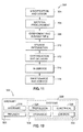
- An embodiment of a method of repairing a composite structure having upper and lower surfaces including the steps of:
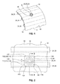
- FIG. 1 shown in Figure 1 is a perspective illustration of a composite structure 10 upon which a repair process may be implemented using a surrogate patch assembly as illustrated in Figures 4-9 .
- the preparation of a rework area 20 may include a thermal survey and/or a moisture removal process which may employ the surrogate patch assembly 50 ( Figs. 4-9 ) as disclosed herein and which may be fabricated of low-cost material in a relatively short period of time as will be described in greater detail below.
- the composite structure 10 may include a skin 14 formed of plies 12 of composite material and wherein the skin 14 may have upper and lower surfaces 16, 18.
- the composite structure 10 may include the rework area 20 formed in the skin 14 and from which composite material may be removed in preparation for receiving a patch 40.
- the rework area 20 may be formed in the upper surface 16 and may extend at least partially through the skin 14 although the rework area 20 may be formed in the lower surface 18 and/or may extend through a thickness of the skin 14.
- Various heat sinks 28 may be mounted to the lower surface 18 opposite the rework area 20 such as, without limitation, stringers, stiffeners, and spars which may draw heat away from the rework area 20 during the repair.
- Figures 2-3 illustrate a stringer 30 mounted to a lower surface 18 and having flanges 32 that extend along a portion of the rework area 20 on a right-hand side thereof and which may draw heat away from the rework area 20.
- the remainder of the rework area 20 may lack any structure which would otherwise draw heat away from the rework area 20.
- the thermal survey may assist in identifying locations of a bondline 46 ( Fig. 3 ) between the patch 40 and the rework area 20 that require a greater amount of heat input relative to other areas of the bondline.
- the thermal survey may also assist in identifying locations of the rework area 20 that may require the temporary application of insulation to the composite structure 10 in order to attain substantial temperature uniformity throughout the bondline 46 ( Fig. 3 ).
- the vacuum bag assembly 100 may comprise a heating blanket 104 or other heating equipment.
- the heating blanket 104 may include wiring 106 coupled to a power source (not shown) for heating the rework area 20 to the desired temperature during the thermal survey or moisture removal process.
- the vacuum bag assembly 100 may include a bagging film 116 covering the heating blanket 104 and may be sealed to the upper surface 16 of the composite structure 10 by means of sealant 122 tape.
- a vacuum probe 118 may extend from the bagging film 116 to provide a means for evacuating volatiles, air and/or gas from the rework area 20.
- the vacuum bag assembly 100 may comprise a caul plate 102 positioned above a non-porous parting film 108 (e.g., peel ply) to facilitate the application of uniform pressure to the patch 40.
- the parting film may prevent adhesion of the caul plate 102 to layers directly below the caul plate 102.
- the parting film may, in turn, be positioned over a porous bleeder layer 112 which may be positioned over a porous parting film 110 to facilitate the escape of volatiles during the bonding of the patch 40 to the composite structure 10.
- the patch 40 may be received within the rework area 20 and may include a scarf 44 formed on the patch edge 42 and substantially matching the scarf 24 formed at a rework taper angle ⁇ rework area of the rework area 20.
- the surrogate patch body 52 may include a plurality of plies corresponding to the plies 12 of the composite structure 10.
- the surrogate patch assembly 50 may comprise a surrogate patch body 52 which may be formed of a material for drawing moisture from the rework area 20.
- the material may comprises wool, cotton, silk, linen, polyester, nylon and acrylic and any other material or combination thereof.
- embodiments of the surrogate patch body may include composite material such as, without limitation, fiber-reinforced polymeric materials.
- the surrogate patch assembly 50 may further include one or more sensors such as a thermal sensor 70 which may be mounted to the surrogate patch body 52 for sensing temperature of the rework area 20 during a thermal survey.
- the sensor may also comprise a moisture sensor 74 for sensing moisture that may be drawn from the rework area 20 into the surrogate patch body 52 during the moisture removal process.
- the thermal sensor 70 may comprise any suitable temperature measuring instrumentation including, but not limited to, thermocouples 72 and any other suitable elements for sensing the temperature of the rework area 20 and/or the surrogate patch body 52.
- the surrogate patch body 52 of the surrogate patch assembly 50 is preferably formed of a material that possesses thermal properties similar to the composite material from which the final patch 40 ( Fig. 3 ) is formed.
- the surrogate patch body 52 is preferably formed of a material that has a specific heat capacity and/or a thermal conductivity that is substantially equivalent to the specific heat capacity and thermal conductivity of the patch.
- the thermal conductivity of the patch is preferably measured in the transverse out-of-plane direction in order to simulate the direction along which heat may flow during the repair process.
- the patch 40 may be fabricated from epoxy pre-impregnated carbon fiber tape and/or fabric.
- the composite material from which the patch may be formed may comprise any suitable pre-impregnated or wet layup composite material and is not limited to the materials disclosed herein.
- the specific heat capacity, thermal conductivity and other thermal properties of the composite material are preferably those properties exhibited by the composite material when fully cured and at a specific or certain fiber volume content and density.
- the thermal properties may comprise a thermal conductivity in the range of from approximately 0.01 W/mK to approximately 1.0 W/mK wherein such properties are measured at a temperature To of approximately 20°C (i.e., room temperature).
- the surrogate patch body 52 may be formed of a material having a thermal conductivity similar to the above mentioned range of 0.01 W/mK to approximately 1.0 W/mK. In an embodiment, the thermal conductivity of the surrogate patch body 52 may be approximately 0.04 W/mK. However, the surrogate patch body 52 may be formed of a material having any thermal conductivity which is complementary to or substantially equal to the thermal conductivity of the material from which the patch 40 ( Fig. 3 ) is formed.
- the heating characteristics of the patch may be substantially duplicated without the need for fabricating a conventional surrogate patch of individually-cut composite plies as described above.
- the expense and time normally associated with conventional surrogate composite patches can be substantially reduced.
- the surrogate patch body 52 may be formed of a material which may have a specific heat capacity that is preferably in the range of the specific heat capacity of the composite material from which the patch 40 ( Fig. 3 ) may be formed.
- the surrogate patch body 52 may be formed of material having a specific heat capacity in the range of from approximately 600 J/(kgK) to approximately 1100 J/(kgK) and preferably approximately 830 J/(kgK) measured at a temperature To of approximately 273K (i.e., room temperature).
- such specific heat capacity and thermal conductivity represent the specific heat capacity and thermal conductivity of the epoxy pre-impregnated carbon fiber tape and/or fabric from which the patch may be formed and are not to be construed as limiting alternative thermal properties of the surrogate patch assembly 50.
- the surrogate patch body 52 material may be formed of natural or synthetic material or any combination thereof.
- the material from which the surrogate patch body 52 may be formed may comprise wool, cotton, silk, linen, polyester, nylon and acrylic or any other suitable material which may substantially duplicate the thermal properties (i.e., specific heat capacity and thermal conductivity) of the material from which the final patch may be formed.
- the material may comprise a non-woven material or fabric which may be comprised of bonded fibers.
- the surrogate patch body 52 may be formed of felt due to its favorable wicking properties and favorable thermal insulating properties.
- the wicking properties of felt are such that fluid may be drawn away from the rework area 20 and into the surrogate patch body 52 due to capillary action in the felt material.
- the thermal conductivity of wool felt in an embodiment, is approximately 0.04 W/mK which may be compatible with the thermal conductivity of composite materials from which the patch may be formed.
- the surrogate patch body 52 may preferably be formed of felt, the surrogate patch body 52 may be formed of any suitable material that may draw moisture from the rework area 20 when the surrogate patch body 52 is placed into contact therewith.
- the surrogate patch body 52 may be formed of alternative materials such as woven materials having high absorbency at elevated temperatures similar to the curing temperatures associated with composite repair.
- the surrogate patch body 52 material is preferably such that heat such as from a heating blanket 104 penetrates the thickness of the surrogate patch body 52 to facilitate an accurate measurement of the temperature at the bondline 48 between the surrogate patch body 52 and the rework area 20.
- the surrogate patch body 52 may be formed of a plurality of layers 60 which may be arranged in stacked formation.
- the patch assembly layers 60 may be formed such that the layer edges 62 collectively define a taper angle which is substantially similar to the rework taper angle ⁇ rework area as illustrated in Figure 4 .
- the layers 60 of the surrogate patch body 52 may be of substantially equivalent width such that when the layers 60 are assembled in the stacked arrangement, the layer edges 62 are in substantial alignment with one another.
- the assembled surrogate patch body 52 may comprise the plurality of layers 60 that may be received within the rework area 20.
- the surrogate patch assembly 50 may be separated from the rework area 20 by a parting film which may be a non-porous parting film 108 or a porous parting film 110.
- the surrogate patch assembly 50 may include one or more thermal sensors 70 mounted at strategic locations on the rework area 20 in order to monitor temperatures at such locations of the rework area 20 during the application of heat.
- thermal sensors 70 such as thermocouples 72 may be installed at a bottom center 26 of the rework area 20 and on a taper of the boundary 22 of the rework area 20 in order to monitor the temperature profile.
- the surrogate patch body 52 may include one or more thermal sensors 70 in order to measure temperatures during the thermal survey.
- the surrogate patch body 52 may include a thermal sensor 70 mounted on a top surface 54 such as at a center thereof as illustrated in Figure 4 .
- a thermal sensor 70 may also be mounted within the surrogate patch body 52 such as between the top and bottom surfaces 54, 56.
- fabrication of the surrogate patch body 52 as a stack of layers 60 may facilitate installation of thermal sensors 70 at different locations within the surrogate patch body 52.
- the thermal sensors 70 may also be arranged along a perimeter 58 of the surrogate patch body 52.
- the sensors may be attached to the surrogate patch body 52 by any suitable means including, but not limited to, bonding and mechanical attachment.
- the thermal sensors 70 may be mounted at any location within the rework area 20 such as on the rework area 20 scarf 24 or at the bottom center 26 of the rework area 20 or at locations that are opposite the location of heat sinks such as the stringer 30 that may at least partially overlap a portion of the rework area 20.
- the surrogate patch assembly 50 may further include the moisture sensors 74 for sensing the presence of moisture and/or the relative content of moisture which may be contained within the rework area 20.
- the moisture sensors 74 may comprise conventional moisture detection strips such as, without limitation, cobalt chloride moisture detection strips or other chemical composition moisture detection strips which may change color in the presence of a sufficiently high level of moisture or water.
- any suitable sensor configuration for detecting the presence of moisture such as water may be implemented into the surrogate patch assembly 50.
- the moisture sensor 74 may comprise sensors which operate using electrochemical impedance spectroscopy (EIS) or any other suitable sensing technology.
- EIS electrochemical impedance spectroscopy
- the moisture sensors 74 may be selectively configured to provide an indication (e.g., a visual indication) regarding the presence of moisture in the surrogate patch body 52 which may be drawn from the rework area 20. Such moisture may be drawn from the rework area 20 when the surrogate patch body 52 is in contact therewith and/or during the application of heat.
- the moisture sensors 74 are preferably mounted in a suitable arrangement on the surrogate patch body 52 such as in spaced relation to one another along the top surface 54 of the surrogate patch body 52 as illustrated in Figure 6 and described in greater detail below.
- the surrogate patch assembly 50 wherein the surrogate patch body 52 is provided in an embodiment comprising a unitary structure of a single layer or ply as opposed to the arrangement of layers 60 illustrated in Figure 4 .
- the surrogate patch body 52 may be formed as a thickness that approximates the thickness of the rework area 20 into which the surrogate patch body 52 is received.
- the perimeter 58 of the surrogate patch body 52 may include a scarf 64 formed at a patch taper angle ⁇ surrogate which is preferably complementary to the rework taper angle ⁇ rework area such that the surrogate patch body 52 is received in intimate contact with the rework area 20.
- the surrogate patch body 52 may be separated from the rework area 20 by porous or non-porous parting film 108 such as fluorinated ethylene propylene (FEP) or other similar heat resistant and/or non-sticking material to allow release of the surrogate patch body 52 from the rework area 20 following completion of the thermal survey and/or moisture removal process.
- FEP fluorinated ethylene propylene
- the thermal sensors 70 may be mounted to the rework area 20 in the areas noted as well as in areas adjacent to the rework area 20 and may be coupled to instrumentation (not shown) such as a data acquisition system (not shown) by means of sensor wiring 76 or by wireless means.
- the thermal sensors 70 and/or moisture sensors 74 mounted on the surrogate patch body 52 may be coupled to instrumentation by means of sensor wiring 76 to facilitate measuring and recording of temperature and/or moisture within the surrogate patch body 52.
- thermocouples 72 and/or moisture sensors 74 may be located on the top surface 54 of the composite structure 10 opposite the stringer 30 which may draw heat away from the rework area 20.
- the thermal sensors 70 may provide a means for monitoring temperature to indicate that insulation may be required on the stringer 30 or that separate heating of the stringer 30 or areas adjacent thereto may be required in order to heat up the rework area 20 at the desired rate and maintain the patch within the desired temperature range.
- the surrogate patch body 52 may include one or more moisture sensors 74 such as the moisture sensor 74 located at the center of the surrogate patch body 52.
- moisture sensors 74 may be distributed along the top surface 54 of the surrogate patch body 52 to facilitate the identification of areas in the rework area 20 from which moisture is drawn.
- the thermal sensors 70 and/or moisture sensors 74 may provide data regarding a thermal profile and/or moisture profile of the rework area 20.
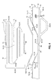
- the surrogate patch system 48 which may comprise the surrogate patch assembly 50 and which may further include a vacuum bag assembly 100 comprising a bagging film 116 enveloping a heating blanket 104 which may cover the patch assembly when installed within the rework area 20.
- the surrogate patch body 52 may be separated from the rework area 20 by means of the porous and/or non-porous parting film 110, 108 depending on whether the thermal survey may include a moisture removal process.
- the surrogate patch assembly 50 as disclosed herein provides a means for combining the thermal survey and moisture removal such that a single heat cycle is imposed on the composite structure 10.
- the vacuum bag assembly 100 can be seen as including the bagging film 116 which may be sealed to the top surface 54 of the composite structure 10 by means of sealant 122 such as tape sealant 122 conventionally used in vacuum bagging operations.
- the bagging film 116 may envelope a breather layer 114 which may cover a heating blanket 104 and which may extend on one or both sides of the heating blanket 104 to the sealant 122 area.
- the breather layer 114 may extend underneath a vacuum probe 118 which may be disposed on a side of the heating blanket 104 in order to facilitate the substantially uniform application of vacuum pressure on the surrogate patch body 52 during the thermal cycling and/or moisture removal process.
- a caul plate 102 may be positioned underneath the heating blanket 104 in order to provide uniform application of pressure to the surrogate patch body 52.
- the caul plate 102 may be formed of any suitable rigid or semi-rigid material including, but not limited to, a rubber caul material such as cured silicon rubber sheet and/or a metallic material or any combination of metallic and nonmetallic materials.
- the caul plate 102 may be separated from the surrogate patch body 52 by means of the parting film which may be formed of any suitable material for preventing adhesion or contact of the caul plate 102 with the rework area 20 and/or surrogate patch body 52.
- the parting film may be perforated (i.e., porous) or non-perforated (i.e., non-porous) and may be formed of any suitable material including fluorinated ethylene propylene (FEP), or any other suitable material.
- FEP fluorinated ethylene propylene
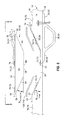
- FIG. 8 shown is a cross-sectional illustration of the surrogate patch body 52 having the vacuum bag mounted thereto without the heating blanket 104. Such an arrangement may be implemented during a moisture removal process.
- the assembly may be installed in an oven or autoclave to facilitate the application of heat to the composite structure 10.
- the vacuum bag includes the vacuum probe 118 for drawing gasses out of the area enveloped by the bagging film 116.
- a vacuum gauge 120 on an opposite side of the vacuum bag assembly 100 provides a means for monitoring vacuum pressure within the vacuum bag.
- the surrogate patch body 52 can be seen as having a substantially uniform thickness.
- the surrogate patch body 52 may be formed of any one of the above-mentioned materials.
- the surrogate patch body 52 may be formed of a flexibly resilient material capable of conforming to the contour or shape of the rework area 20 in three-dimensions.
- the perimeter 58 of the surrogate patch body 52 can be seen as conforming or partially compressing under pressure from the vacuum bag.
- the surrogate patch body 52 may be separated from the bagging film 116 by a breather layer 114 to allow for the escape of moisture.
- the surrogate patch body 52 may be separated from the rework area 20 by means of a porous parting film 108 to prevent contact therebetween while allowing moisture to escape from the rework area 20.
- Thermocouples 72 or other thermal sensors 70 may be installed at strategic locations within the rework area 20 as illustrated in Figure 8 and described above.
- the surrogate patch body 52 may include thermal sensors 70 and/or moisture sensors 74 at locations along the surrogate patch body 52 for monitoring temperature and moisture removal.
- the surrogate patch system 48 may comprise a vacuum bag assembly 100 which may include a bagging film 116 mounted to the structure 10 by means of sealant 122.
- the bagging film 116 may envelope a number of layers such as a breather layer 114, heating blanket 104, caul plate 102, bleeder layer 112, parting film 108, 110, as well as the surrogate patch assembly 50 comprising the surrogate patch body 52.
- the surrogate patch body 52 may have a patch center 68 and a perimeter 58.
- One or more sensors such as moisture sensors 74 or thermal sensors 70 (i.e., thermocouples 72) may be mounted to the surrogate patch body 52 such as along the perimeter 58 and/or patch center 68 or embedded within the surrogate patch body 52.
- the surrogate patch body 52 may be mounted in the rework area 20 and may be separated therefrom by means of the parting film.
- the rework area 20 may be formed in the structure 10 such as along an upper surface 16 thereof.
- the rework area 20 may include the bottom center 26 within which a sensor such as a moisture sensor 74 and/or a thermal sensor 70 (i.e., thermocouple) may be mounted.
- one or more sensors such as thermal sensors 70 may be mounted on a scarf 24 of the rework area 20.
- the upper surface 16 of the structure 10 surrounding the rework area 20 may include thermal sensors 70 such as thermocouples 72 in order to identify temperature variations that may occur as a result of heat drawn from the rework area 20 by heat sinks 28 such as stringers
- the structure may include upper and lower surfaces and may include at least one heat sink which may be disposed at a location relative to the rework area such as on a lower surface of the structure adjacent to the rework area.
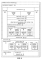
- the method may comprise step 200 including forming the surrogate patch body which may optionally be formed and shaped complementary to the shape of the rework area.
- the surrogate patch body may be formed of woven or non-woven material for drawing moisture from the rework area.
- the surrogate patch body may have top and bottom surfaces and is preferably formed of a material for drawing moisture from the rework area such as during a moisture removal process. Furthermore, the surrogate patch body preferably has thermal properties that are substantially similar to or complementary to the thermal properties of composite material from which the final patch may be formed.
- the surrogate patch body may have a specific heat capacity and/or a thermal conductivity that is substantially equivalent to a specific heat capacity and/or thermal conductivity of epoxy pre-impregnated carbon fiber tape and fabric.
- the thermal properties of the composite material may comprise thermal properties of any composite material and are not limited to epoxy prepregs or carbon fiber tapes but may include non-pre-impregnated and/or wet layup material systems.
- the surrogate patch body may include at least one thermal sensor which may be mounted on the surrogate patch body on the top surface, the bottom surface or which may be embedded within the surrogate patch body or any combination of the above.
- the surrogate patch body may further include at least one moisture sensor which may be mounted on the surrogate patch body at any location such as on a patch center or along a perimeter of the surrogate patch body or a combination of such locations.
- step 202 may comprise mounting one or more thermal sensors on the surrogate patch body for sensing the temperature of the rework area and/or the surrogate patch body.
- thermal sensors such as, without limitation, thermocouples may be mounted on the top and/or bottom surfaces of the surrogate patch body. Thermal sensors may optionally be embedded within the surrogate patch body as is illustrated in Figure 4 and described above. Thermal sensors on the bottom surface of the surrogate patch body may monitor the temperature of the rework area and/or the temperature of the surrogate patch body.
- Step 204 may comprise mounting one or more moisture sensors on the surrogate patch body for sensing moisture that may be drawn from the rework area into the surrogate patch body.
- the surrogate patch body may be formed of any material having a relatively high moisture-absorbing capability as indicated above.
- the surrogate patch body may be formed of materials having relatively high absorbency at the elevated temperatures associated with processing of composite materials.
- step 206 may include mounting one or more thermal sensors on the upper surface of the composite structure.
- thermal sensors may be mounted on the upper surface of the composite structure opposite the location of one or more heat sinks which may be disposed adjacent to the bottom surface of the composite structure or at any location on the upper surface.
- Step 208 may comprise mounting one or more of the thermal sensors in the rework area such as in the bottom center of the rework area and/or on the scarf (i.e., taper angle) of the rework area for monitoring temperatures in the rework area.
- Step 210 in the methodology of repairing the structure may include covering the rework area with a porous parting film such as fluorinated ethylene propylene (FEP) or any other suitable film material for preventing contact of the surrogate patch body with the composite structure and rework area.
- a porous parting film such as fluorinated ethylene propylene (FEP) or any other suitable film material for preventing contact of the surrogate patch body with the composite structure and rework area.
- FEP fluorinated ethylene propylene
- the material from which the surrogate patch body is formed may obviate the need for a parting film.
- Step 212 may include installing the surrogate patch assembly into the rework area such as on top of the porous and/or non-porous parting film.
- the surrogate patch may be installed in a manner illustrated in Figure 8 wherein the surrogate patch body may be formed as a substantially constant thickness unitary or single-layer structure which is substantially conformable to the shape and/or contour of the rework area.
- the surrogate patch body may be formed of a plurality of layers arranged in stacked formation as illustrated in Figure 4 and wherein the layers of material which make up the surrogate patch body are conformable or resiliently flexible or compressible in order to allow for conforming the surrogate patch body to the contour or shape of the rework area.
- step 214 of the methodology may further include covering the surrogate patch body and rework area with a breather layer to facilitate the substantially uniform application of vacuum pressure to the surrogate patch body.
- the method may further include the step of installing a heating blanket or other suitable heating equipment in step 216 and as is illustrated in Figure 7 and 8 .
- the heating blanket may facilitate the heating of the rework area and the surrogate patch body during the thermal survey and/or during the moisture removal process.
- a caul plate 102 ( Fig. 7 ) may optionally be included between the breather layer and the heating blanket 104 as illustrated in Figure 7 in order to provide uniform pressure distribution to the surrogate patch body.
- Step 218 of Figure 10 may comprise installing a breather layer over the heating blanket as illustrated in Figure 7 followed by vacuum bagging in step 220 such that the surrogate patch body and heating blanket are enveloped by the bagging film which may be sealed to the top surface of the composite structure 10 as illustrated in Figure 8 .
- Vacuum may be applied via the vacuum probe illustrated in Figure 8 in order to draw a vacuum on the bagging film which may be monitored by means of a vacuum gauge installed as illustrated in Figure 8 .
- Heat may be applied such as by the heating blanket in step 222 during the drawing of the vacuum in step 224 such that the thermal survey and/or moisture removal process may be performed on the rework area in step 226.
- the thermal survey process may be similar to that which is conventionally performed wherein the rework area may be heated and the temperature monitored. Depending on the temperature measurements, insulation may be locally added to areas of the composite structure such as adjacent to heat sinks or to other areas as indicated above in order to attain substantial temperature uniformity throughout the bondline.
- the heating of the rework area may also be adjusted by adjusting the heating blanket during the thermal survey to attain substantial temperature uniformity.
- the moisture removal process may comprise heating the rework area via the heating blanket and recording moisture data provided by moisture sensors mounted within the surrogate patch body. The moisture removal process may be performed prior to and/or during the thermal survey.
- the surrogate patch body configuration may facilitate the performance of the thermal survey and the moisture removal process in a manner that may eliminate an additional heat cycle typically required in separate thermal survey and moisture removal processes of conventional pre-repair operations.
- the moisture removal process may comprise weighing the surrogate patch body prior to installation into the rework area.
- the surrogate patch body may again be weighed to determine the moisture absorption level which may then be correlated to the moisture content of the rework area.
- the moisture removal process may comprise weighing the surrogate patch body prior to installing the surrogate patch body into the rework area and vacuum bagging the surrogate patch body.
- the method may include heating the rework area after drawing a vacuum on the bagging film. Alternatively, the heating blanket may be omitted and the composite structure may be heated via an oven or in an autoclave. During heating, the temperature of the rework area may be monitored using data from the thermal sensors.
- the heating may result in drying (i.e., moisture removal) of the rework area of the composite structure.
- the surrogate patch body of the surrogate patch assembly may be removed from the rework area and may be weighed in order to determine the amount of moisture drawn out of the rework area.
- exemplary method 300 may include specification and design 304 of the aircraft 302 and material procurement 306.
- component and subassembly manufacturing 308 and system integration 310 of the aircraft 302 takes place.
- the aircraft 302 may go through certification and delivery 312 in order to be placed in service 314.
- routine maintenance and service 316 which may also include modification, reconfiguration, refurbishment, and so on).
- a system integrator may include without limitation any number of aircraft manufacturers and major-system subcontractors; a third party may include without limitation any number of vendors, subcontractors, and suppliers; and an operator may be an airline, leasing company, military entity, service organization, and so on.
- the aircraft 302 produced by exemplary method 300 may include an airframe 318 with a plurality of systems 320 and an interior 322.
- high-level systems 320 include one or more of a propulsion system 324, an electrical system 326, a hydraulic system 328, and an environmental system 330. Any number of other systems may be included.
- an aerospace example is shown, the principles of the disclosed embodiments may be applied to other industries, such as the automotive industry.
- Apparatus and methods embodied herein may be employed during any one or more of the stages of the production and service method 300.
- components or subassemblies corresponding to production process 308 may be fabricated or manufactured in a manner similar to components or subassemblies produced while the aircraft 302 is in service.
- one or more apparatus embodiments, method embodiments, or a combination thereof may be utilized during the production stages 308 and 310, for example, by substantially expediting assembly of or reducing the cost of an aircraft 302.
- one or more of apparatus embodiments, method embodiments, or a combination thereof may be utilized while the aircraft 302 is in service, for example and without limitation, to maintenance and service 316.
Landscapes
- Engineering & Computer Science (AREA)
- Mechanical Engineering (AREA)
- Chemical & Material Sciences (AREA)
- Physics & Mathematics (AREA)
- General Physics & Mathematics (AREA)
- Life Sciences & Earth Sciences (AREA)
- Health & Medical Sciences (AREA)
- Analytical Chemistry (AREA)
- Biochemistry (AREA)
- General Health & Medical Sciences (AREA)
- Immunology (AREA)
- Pathology (AREA)
- Electrochemistry (AREA)
- Chemical Kinetics & Catalysis (AREA)
- Food Science & Technology (AREA)
- Medicinal Chemistry (AREA)
- Investigating Or Analyzing Materials Using Thermal Means (AREA)
- Medicinal Preparation (AREA)
Applications Claiming Priority (2)
| Application Number | Priority Date | Filing Date | Title |
|---|---|---|---|
| US12/633,753 US8545650B2 (en) | 2009-12-08 | 2009-12-08 | Method of repairing a composite structure |
| PCT/US2010/055684 WO2011071622A1 (en) | 2009-12-08 | 2010-11-05 | Surrogate patch for composite repair process |
Publications (2)
| Publication Number | Publication Date |
|---|---|
| EP2509777A1 EP2509777A1 (en) | 2012-10-17 |
| EP2509777B1 true EP2509777B1 (en) | 2015-09-09 |
Family
ID=43813722
Family Applications (1)
| Application Number | Title | Priority Date | Filing Date |
|---|---|---|---|
| EP10779165.9A Active EP2509777B1 (en) | 2009-12-08 | 2010-11-05 | Surrogate patch for composite repair process |
Country Status (11)
| Country | Link |
|---|---|
| US (2) | US8545650B2 (enExample) |
| EP (1) | EP2509777B1 (enExample) |
| JP (1) | JP5963169B2 (enExample) |
| KR (1) | KR101819760B1 (enExample) |
| CN (2) | CN107512014B (enExample) |
| BR (1) | BR112012013817B1 (enExample) |
| CA (1) | CA2783188C (enExample) |
| ES (1) | ES2555984T3 (enExample) |
| PT (1) | PT2509777E (enExample) |
| SG (1) | SG185358A1 (enExample) |
| WO (1) | WO2011071622A1 (enExample) |
Cited By (1)
| Publication number | Priority date | Publication date | Assignee | Title |
|---|---|---|---|---|
| DE102016109121B4 (de) | 2016-05-18 | 2023-03-23 | Airbus Operations Gmbh | Mobiles Heizsystem und Heizverfahren |
Families Citing this family (46)
| Publication number | Priority date | Publication date | Assignee | Title |
|---|---|---|---|---|
| FR2953812B1 (fr) * | 2009-12-11 | 2012-09-07 | Airbus Operations Sas | Procede de reparation d'un fuselage d'aeronef |
| US8444127B2 (en) * | 2009-12-14 | 2013-05-21 | The Boeing Company | High temperature composite patch tool |
| IT1399682B1 (it) * | 2010-03-29 | 2013-04-26 | Alenia Aeronautica Spa | Procedimento e dispositivo per la riparazione di pannelli di materiale composito |
| DE102011006792B4 (de) * | 2011-04-05 | 2017-07-27 | Airbus Operations Gmbh | Verfahren zum Herstellen und Verbinden von faserverstärkten Bauteilen sowie Luft- oder Raumfahrzeug |
| US8720278B1 (en) | 2011-05-05 | 2014-05-13 | The Boeing Company | Method of detecting inconsistencies in composite structures and stress sensitive coatings used therein |
| US9085052B1 (en) * | 2011-05-05 | 2015-07-21 | The Boeing Company | Structural repair having optical witness and method of monitoring repair performance |
| FR2977186B1 (fr) * | 2011-07-01 | 2014-08-22 | Daher Aerospace | Procede de renforcement local d'un panneau composite a renfort fibreux et panneau obtenu par un tel procede |
| US8844108B2 (en) * | 2011-07-12 | 2014-09-30 | The Boeing Company | Large area repair of composite aircraft |
| DE102011086453A1 (de) * | 2011-11-16 | 2013-05-16 | Wobben Properties Gmbh | Heizeinrichtung zur Reparatur oder Herstellung von Komponenten einer Windenergieanlage und Teilen davon sowie Windenergieanlage |
| DE102011122059A1 (de) * | 2011-12-22 | 2013-06-27 | Airbus Operations Gmbh | System und Verfahren zur Reparatur eines Strukturbauteils |
| FR2985213B1 (fr) * | 2011-12-28 | 2016-12-30 | Airbus Operations Sas | Panneau composite auto-raidi et procede de realisation |
| US9919388B2 (en) * | 2012-01-26 | 2018-03-20 | General Electric Company | Method for repairing a laminated article having a damaged area |
| FR2991228B1 (fr) | 2012-05-29 | 2015-03-06 | Airbus Operations Sas | Procede et dispositif de realisation d'un panneau composite auto-raidi |
| FR2999970B1 (fr) | 2012-12-20 | 2015-06-19 | Airbus Operations Sas | Procede de realisation d'une preforme textile a fibres continues par circulation d'un flux de gaz chaud a travers un ensemble fibreux |
| WO2014107736A1 (en) * | 2013-01-07 | 2014-07-10 | University Of Washington Through Its Center For Commercialization | Embedded section heater for bonding composite structures, and associated apparatuses and methods |
| US9817452B2 (en) * | 2013-01-11 | 2017-11-14 | The Boeing Company | System and method for thermal management guidance |
| FR3015433B1 (fr) | 2013-12-23 | 2016-02-12 | Airbus Operations Sas | Ensemble pour aeronef comprenant un mat d'accrochage integre a la nacelle et agence en partie arriere du fuselage |
| CN103770346B (zh) * | 2014-01-07 | 2016-05-04 | 杭州华聚复合材料有限公司 | 一种热塑性蜂窝板的修复方法 |
| US10583616B2 (en) | 2014-06-20 | 2020-03-10 | The Boeing Company | Forming tools and flexible ultrasonic transducer arrays |
| US10768128B2 (en) | 2014-07-22 | 2020-09-08 | The Boeing Company | Systems and methods of monitoring a thermal protection system |
| US20180036973A1 (en) * | 2015-02-23 | 2018-02-08 | Sikorsky Aircraft Corporation | Composite repair method |
| US9945735B2 (en) * | 2015-03-26 | 2018-04-17 | The Boeing Company | System and method to monitor a thermal environment of a composite structure using a thermochromatic witness assembly |
| US9873527B2 (en) * | 2015-03-26 | 2018-01-23 | The Boeing Company | System and method to map a thermal profile of a composite structure using a thermochromatic witness assembly |
| US20160370309A1 (en) * | 2015-06-22 | 2016-12-22 | The Boeing Company | Methods and systems for determining an allowable moisture content in a composite structure |
| FR3042779B1 (fr) * | 2015-10-27 | 2018-07-13 | Airbus Operations | Procede de reparation d'une structure d'aeronef a partir de plaques deformables |
| US10695993B2 (en) | 2016-01-15 | 2020-06-30 | GM Global Technology Operations LLC | In-situ polymerization of polyamides for composite part repair |
| US10288554B2 (en) * | 2016-01-27 | 2019-05-14 | The Boeing Company | Moisture detecting bleeder materials |
| US10927684B2 (en) * | 2016-02-08 | 2021-02-23 | Raytheon Technologies Corporation | Repairing a coating with a pre-configured coating patch |
| US10589477B2 (en) | 2016-05-02 | 2020-03-17 | GM Global Technology Operations LLC | Cosmetic repair of a thermoplastic carbon fiber composite |
| US10774648B2 (en) | 2016-10-04 | 2020-09-15 | General Electric Company | Methods and features for CMC component repairs |
| US20180147800A1 (en) * | 2016-11-30 | 2018-05-31 | The Boeing Company | Configurable Cooling Assembly and Cooling Method |
| JP6847679B2 (ja) * | 2017-01-20 | 2021-03-24 | 三菱重工業株式会社 | 複合材の修理方法 |
| US10656074B2 (en) * | 2017-05-02 | 2020-05-19 | The Boeing Company | Bondline sensors |
| US10611104B2 (en) | 2017-06-15 | 2020-04-07 | GM Global Technology Operations LLC | Heating elements for repair of molding defects for carbon fiber thermoplastic composites |
| US20190064003A1 (en) * | 2017-08-29 | 2019-02-28 | Te Wire & Cable Llc | Multipoint Temperature Profiling and Monitoring System for Composite Repair |
| DE102017122630A1 (de) * | 2017-09-28 | 2019-03-28 | Airbus Operations Gmbh | Vakuumfolie mit belüftungseigenschaften |
| DE202017105967U1 (de) * | 2017-09-29 | 2018-01-31 | Airbus Operations Gmbh | Farbbasiertes Heizsystem |
| JP7036694B2 (ja) * | 2018-09-12 | 2022-03-15 | 三菱重工業株式会社 | 修理パッチ及び複合材の修理方法 |
| EP4187080B1 (en) * | 2019-03-21 | 2025-09-03 | Siemens Gamesa Renewable Energy A/S | Method of repairing a damaged spar cap of a wind turbine blade of a wind turbine |
| US11554559B2 (en) * | 2019-12-11 | 2023-01-17 | The Boeing Company | Caul plate for irregular surface |
| FR3106772B1 (fr) * | 2020-01-31 | 2022-01-28 | Ecole Nat Superieure D’Arts Et Metiers | Tapis chauffant souple pour le preformage ou la consolidation de pieces composites |
| CN111392028A (zh) * | 2020-04-13 | 2020-07-10 | 中国商用飞机有限责任公司 | 用于机翼长桁的长桁修理件以及修理机翼长桁的方法 |
| US12397516B2 (en) | 2020-12-07 | 2025-08-26 | General Electric Company | Method for repairing composite components using a support member |
| CN113877865B (zh) * | 2021-11-10 | 2022-12-09 | 段瑞 | 一种农业大棚膜内部清洗器 |
| US20240359413A1 (en) * | 2023-04-26 | 2024-10-31 | The Boeing Company | Systems and methods for composite stringer package construction and compacted stringer packages |
| CN119610737B (zh) * | 2024-12-04 | 2025-10-28 | 中建材(上海)航空技术有限公司 | 一种复合材料修复方法及修复结构 |
Citations (1)
| Publication number | Priority date | Publication date | Assignee | Title |
|---|---|---|---|---|
| DE202007013755U1 (de) * | 2007-10-02 | 2008-03-13 | Kiersch Composite Gmbh | Verbundwerkstoffelement |
Family Cites Families (23)
| Publication number | Priority date | Publication date | Assignee | Title |
|---|---|---|---|---|
| US4221962A (en) * | 1978-04-24 | 1980-09-09 | Northrop Corporation | Fiber-optic moisture sensor for composite structures |
| US4622091A (en) * | 1984-11-29 | 1986-11-11 | The Boeing Company | Resin film infusion process and apparatus |
| US4652319A (en) | 1984-12-03 | 1987-03-24 | Hammond Russell E | Method of curing patches on contoured surfaces |
| US4808253A (en) | 1987-11-06 | 1989-02-28 | Grumman Aerospace Corporation | Method and apparatus for performing a repair on a contoured section of a composite structure |
| GB2213596A (en) | 1988-01-07 | 1989-08-16 | Protimeter Plc | Disposable humidity sensor |
| JP2796123B2 (ja) * | 1989-05-26 | 1998-09-10 | 神鋼パンテック株式会社 | グラスライニング鋼製機器のライニングガラス層の破損局部の補修方法および装置 |
| US5145541A (en) | 1989-07-07 | 1992-09-08 | Hexcel Corporation | Low energy cured composite repair system based on imidazole-blocked naphthyl-diisocyanates |
| US6527849B2 (en) * | 1990-06-19 | 2003-03-04 | Carolyn M. Dry | Self-repairing, reinforced matrix materials |
| US5442156A (en) | 1991-04-09 | 1995-08-15 | The Boeing Company | Heating apparatus for composite structure repair |
| US5379689A (en) | 1993-07-29 | 1995-01-10 | General Electric Company | Composite repair press for manufacturing and repairing a workpiece made from a composite material |
| US5833795A (en) | 1996-09-19 | 1998-11-10 | Mcdonnell Douglas Corporation | Magnetic particle integrated adhesive and associated method of repairing a composite material product |
| US6561247B2 (en) | 1998-06-29 | 2003-05-13 | General Electric Company | Method and apparatus for repairing a discrete damaged portion of an article surface |
| US6385836B1 (en) * | 2000-06-30 | 2002-05-14 | Lockheed Martin Corporation | Method for composite material repair |
| GB2375742A (en) | 2001-05-23 | 2002-11-27 | Monarch Vulcanising Systems Lt | Tyre repair patch |
| US6761783B2 (en) * | 2002-04-09 | 2004-07-13 | The Boeing Company | Process method to repair bismaleimide (BMI) composite structures |
| JP2005526261A (ja) * | 2002-05-15 | 2005-09-02 | グラクソ グループ リミテッド | 医薬包装内の温度および水分プロファイルを測定するための微小電気機械システムおよび方法 |
| US6976519B2 (en) * | 2002-12-11 | 2005-12-20 | Bh Thermal, Inc. | Portable curing system for use with vacuum bag repairs and the like |
| US20060027308A1 (en) * | 2004-08-05 | 2006-02-09 | Mackenzie M S | Method and apparatus for curing patches on composite structures having complex substrates |
| US20070095457A1 (en) | 2005-11-02 | 2007-05-03 | The Boeing Company | Fast line maintenance repair method and system for composite structures |
| US8043453B2 (en) * | 2005-12-23 | 2011-10-25 | The Boeing Company | System and method for reworking composites |
| GB2440954B (en) * | 2006-08-18 | 2008-12-17 | Insensys Ltd | Structural monitoring |
| DE102007013755B4 (de) | 2007-03-22 | 2020-10-29 | Te Connectivity Germany Gmbh | Indikatorelement für einen magnetischen Drehwinkelgeber |
| SG151151A1 (en) * | 2007-09-11 | 2009-04-30 | Aircraft Plastics Australia Pt | Aircraft plastics repair |
-
2009
- 2009-12-08 US US12/633,753 patent/US8545650B2/en active Active
-
2010
- 2010-11-05 CN CN201710704803.9A patent/CN107512014B/zh active Active
- 2010-11-05 WO PCT/US2010/055684 patent/WO2011071622A1/en not_active Ceased
- 2010-11-05 SG SG2012073532A patent/SG185358A1/en unknown
- 2010-11-05 CA CA2783188A patent/CA2783188C/en active Active
- 2010-11-05 BR BR112012013817-0A patent/BR112012013817B1/pt active IP Right Grant
- 2010-11-05 CN CN201080054521.5A patent/CN102686386B/zh active Active
- 2010-11-05 JP JP2012543112A patent/JP5963169B2/ja active Active
- 2010-11-05 PT PT107791659T patent/PT2509777E/pt unknown
- 2010-11-05 ES ES10779165.9T patent/ES2555984T3/es active Active
- 2010-11-05 EP EP10779165.9A patent/EP2509777B1/en active Active
- 2010-11-05 KR KR1020127009873A patent/KR101819760B1/ko active Active
-
2013
- 2013-08-28 US US14/012,676 patent/US9381730B2/en active Active
Patent Citations (1)
| Publication number | Priority date | Publication date | Assignee | Title |
|---|---|---|---|---|
| DE202007013755U1 (de) * | 2007-10-02 | 2008-03-13 | Kiersch Composite Gmbh | Verbundwerkstoffelement |
Cited By (1)
| Publication number | Priority date | Publication date | Assignee | Title |
|---|---|---|---|---|
| DE102016109121B4 (de) | 2016-05-18 | 2023-03-23 | Airbus Operations Gmbh | Mobiles Heizsystem und Heizverfahren |
Also Published As
| Publication number | Publication date |
|---|---|
| PT2509777E (pt) | 2015-12-01 |
| US8545650B2 (en) | 2013-10-01 |
| EP2509777A1 (en) | 2012-10-17 |
| CN102686386B (zh) | 2017-08-11 |
| JP5963169B2 (ja) | 2016-08-03 |
| US20110132523A1 (en) | 2011-06-09 |
| JP2013512808A (ja) | 2013-04-18 |
| KR20120112385A (ko) | 2012-10-11 |
| KR101819760B1 (ko) | 2018-02-28 |
| BR112012013817A2 (pt) | 2021-08-31 |
| WO2011071622A1 (en) | 2011-06-16 |
| CN102686386A (zh) | 2012-09-19 |
| CA2783188A1 (en) | 2011-06-16 |
| BR112012013817B1 (pt) | 2022-03-29 |
| CN107512014A (zh) | 2017-12-26 |
| ES2555984T3 (es) | 2016-01-12 |
| CA2783188C (en) | 2019-01-15 |
| US9381730B2 (en) | 2016-07-05 |
| SG185358A1 (en) | 2013-01-30 |
| CN107512014B (zh) | 2019-11-29 |
| US20140000788A1 (en) | 2014-01-02 |
Similar Documents
| Publication | Publication Date | Title |
|---|---|---|
| EP2509777B1 (en) | Surrogate patch for composite repair process | |
| CN102183444B (zh) | 在铺层面内方向上测试气体渗透率的测试装置及其方法 | |
| US10189191B2 (en) | Collection of process data using in-situ sensors | |
| US9446575B1 (en) | Monitoring composite manufacturing and repair processes using chromatic films | |
| CN104677928B (zh) | 一种连续纤维增强树脂基复合材料各向异性热膨胀系数的测试方法 | |
| US20140013825A1 (en) | Testing apparatus for testing air permeability on thickness direction of plastic matrix, and method therefor | |
| US20140061962A1 (en) | Detection, Monitoring, and Management of Gas Presence, Gas Flow and Gas Leaks in Composites Manufacturing | |
| EP2599615B1 (en) | Reducing porosity in composite structures | |
| US10828880B1 (en) | Method of fusing thermoplastic composite structures | |
| EP2671708B1 (en) | Method and system for leak detection in vacuum bagging | |
| Hubert et al. | Out-of-autoclave prepreg processing | |
| US20140346405A1 (en) | Method for Fabricating Composite Porosity Standards | |
| US20160282198A1 (en) | System and method to monitor a thermal environment of a composite structure using a thermochromatic witness assembly | |
| CN110779846B (zh) | 非饱和浸渍纤维/树脂预浸料的气体面内渗透率测试方法 | |
| JP5381007B2 (ja) | 繊維強化プラスチックパネルの製造方法および製造装置 | |
| EP3593972A1 (en) | Panel structure for an aircraft and manufacturing method thereof | |
| Larobina et al. | An integrated approach to analyze long-term moisture transport in honeycomb-core sandwich panels | |
| CN116659712A (zh) | 一种视觉指示过载薄层复合材料传感器及其制造方法 | |
| HK1131366A (en) | Collection of process data using in-situ sensors |
Legal Events
| Date | Code | Title | Description |
|---|---|---|---|
| PUAI | Public reference made under article 153(3) epc to a published international application that has entered the european phase |
Free format text: ORIGINAL CODE: 0009012 |
|
| 17P | Request for examination filed |
Effective date: 20120620 |
|
| AK | Designated contracting states |
Kind code of ref document: A1 Designated state(s): AL AT BE BG CH CY CZ DE DK EE ES FI FR GB GR HR HU IE IS IT LI LT LU LV MC MK MT NL NO PL PT RO RS SE SI SK SM TR |
|
| DAX | Request for extension of the european patent (deleted) | ||
| 17Q | First examination report despatched |
Effective date: 20140523 |
|
| GRAP | Despatch of communication of intention to grant a patent |
Free format text: ORIGINAL CODE: EPIDOSNIGR1 |
|
| RIC1 | Information provided on ipc code assigned before grant |
Ipc: G01K 13/00 20060101ALN20150105BHEP Ipc: B29C 73/16 20060101AFI20150105BHEP Ipc: B32B 43/00 20060101ALI20150105BHEP Ipc: B29C 73/10 20060101ALI20150105BHEP |
|
| INTG | Intention to grant announced |
Effective date: 20150203 |
|
| REG | Reference to a national code |
Ref country code: DE Ref legal event code: R079 Ref document number: 602010027437 Country of ref document: DE Free format text: PREVIOUS MAIN CLASS: B29C0073100000 Ipc: B29C0073160000 |
|
| GRAP | Despatch of communication of intention to grant a patent |
Free format text: ORIGINAL CODE: EPIDOSNIGR1 |
|
| INTG | Intention to grant announced |
Effective date: 20150701 |
|
| RIC1 | Information provided on ipc code assigned before grant |
Ipc: B32B 43/00 20060101ALI20150622BHEP Ipc: G01K 13/00 20060101ALN20150622BHEP Ipc: B29C 73/10 20060101ALI20150622BHEP Ipc: B29C 73/16 20060101AFI20150622BHEP |
|
| GRAS | Grant fee paid |
Free format text: ORIGINAL CODE: EPIDOSNIGR3 |
|
| GRAA | (expected) grant |
Free format text: ORIGINAL CODE: 0009210 |
|
| AK | Designated contracting states |
Kind code of ref document: B1 Designated state(s): AL AT BE BG CH CY CZ DE DK EE ES FI FR GB GR HR HU IE IS IT LI LT LU LV MC MK MT NL NO PL PT RO RS SE SI SK SM TR |
|
| REG | Reference to a national code |
Ref country code: GB Ref legal event code: FG4D |
|
| REG | Reference to a national code |
Ref country code: AT Ref legal event code: REF Ref document number: 747773 Country of ref document: AT Kind code of ref document: T Effective date: 20150915 Ref country code: CH Ref legal event code: EP |
|
| REG | Reference to a national code |
Ref country code: IE Ref legal event code: FG4D |
|
| REG | Reference to a national code |
Ref country code: DE Ref legal event code: R096 Ref document number: 602010027437 Country of ref document: DE |
|
| REG | Reference to a national code |
Ref country code: FR Ref legal event code: PLFP Year of fee payment: 6 |
|
| REG | Reference to a national code |
Ref country code: PT Ref legal event code: SC4A Free format text: AVAILABILITY OF NATIONAL TRANSLATION Effective date: 20151117 |
|
| REG | Reference to a national code |
Ref country code: SE Ref legal event code: TRGR |
|
| REG | Reference to a national code |
Ref country code: ES Ref legal event code: FG2A Ref document number: 2555984 Country of ref document: ES Kind code of ref document: T3 Effective date: 20160112 |
|
| REG | Reference to a national code |
Ref country code: NL Ref legal event code: MP Effective date: 20150909 |
|
| PG25 | Lapsed in a contracting state [announced via postgrant information from national office to epo] |
Ref country code: LV Free format text: LAPSE BECAUSE OF FAILURE TO SUBMIT A TRANSLATION OF THE DESCRIPTION OR TO PAY THE FEE WITHIN THE PRESCRIBED TIME-LIMIT Effective date: 20150909 Ref country code: NO Free format text: LAPSE BECAUSE OF FAILURE TO SUBMIT A TRANSLATION OF THE DESCRIPTION OR TO PAY THE FEE WITHIN THE PRESCRIBED TIME-LIMIT Effective date: 20151209 Ref country code: GR Free format text: LAPSE BECAUSE OF FAILURE TO SUBMIT A TRANSLATION OF THE DESCRIPTION OR TO PAY THE FEE WITHIN THE PRESCRIBED TIME-LIMIT Effective date: 20151210 Ref country code: FI Free format text: LAPSE BECAUSE OF FAILURE TO SUBMIT A TRANSLATION OF THE DESCRIPTION OR TO PAY THE FEE WITHIN THE PRESCRIBED TIME-LIMIT Effective date: 20150909 Ref country code: LT Free format text: LAPSE BECAUSE OF FAILURE TO SUBMIT A TRANSLATION OF THE DESCRIPTION OR TO PAY THE FEE WITHIN THE PRESCRIBED TIME-LIMIT Effective date: 20150909 |
|
| REG | Reference to a national code |
Ref country code: LT Ref legal event code: MG4D |
|
| REG | Reference to a national code |
Ref country code: AT Ref legal event code: MK05 Ref document number: 747773 Country of ref document: AT Kind code of ref document: T Effective date: 20150909 |
|
| PG25 | Lapsed in a contracting state [announced via postgrant information from national office to epo] |
Ref country code: RS Free format text: LAPSE BECAUSE OF FAILURE TO SUBMIT A TRANSLATION OF THE DESCRIPTION OR TO PAY THE FEE WITHIN THE PRESCRIBED TIME-LIMIT Effective date: 20150909 Ref country code: HR Free format text: LAPSE BECAUSE OF FAILURE TO SUBMIT A TRANSLATION OF THE DESCRIPTION OR TO PAY THE FEE WITHIN THE PRESCRIBED TIME-LIMIT Effective date: 20150909 |
|
| PG25 | Lapsed in a contracting state [announced via postgrant information from national office to epo] |
Ref country code: NL Free format text: LAPSE BECAUSE OF FAILURE TO SUBMIT A TRANSLATION OF THE DESCRIPTION OR TO PAY THE FEE WITHIN THE PRESCRIBED TIME-LIMIT Effective date: 20150909 |
|
| PG25 | Lapsed in a contracting state [announced via postgrant information from national office to epo] |
Ref country code: SK Free format text: LAPSE BECAUSE OF FAILURE TO SUBMIT A TRANSLATION OF THE DESCRIPTION OR TO PAY THE FEE WITHIN THE PRESCRIBED TIME-LIMIT Effective date: 20150909 Ref country code: IS Free format text: LAPSE BECAUSE OF FAILURE TO SUBMIT A TRANSLATION OF THE DESCRIPTION OR TO PAY THE FEE WITHIN THE PRESCRIBED TIME-LIMIT Effective date: 20160109 Ref country code: EE Free format text: LAPSE BECAUSE OF FAILURE TO SUBMIT A TRANSLATION OF THE DESCRIPTION OR TO PAY THE FEE WITHIN THE PRESCRIBED TIME-LIMIT Effective date: 20150909 Ref country code: CZ Free format text: LAPSE BECAUSE OF FAILURE TO SUBMIT A TRANSLATION OF THE DESCRIPTION OR TO PAY THE FEE WITHIN THE PRESCRIBED TIME-LIMIT Effective date: 20150909 |
|
| PG25 | Lapsed in a contracting state [announced via postgrant information from national office to epo] |
Ref country code: AT Free format text: LAPSE BECAUSE OF FAILURE TO SUBMIT A TRANSLATION OF THE DESCRIPTION OR TO PAY THE FEE WITHIN THE PRESCRIBED TIME-LIMIT Effective date: 20150909 Ref country code: PL Free format text: LAPSE BECAUSE OF FAILURE TO SUBMIT A TRANSLATION OF THE DESCRIPTION OR TO PAY THE FEE WITHIN THE PRESCRIBED TIME-LIMIT Effective date: 20150909 Ref country code: RO Free format text: LAPSE BECAUSE OF FAILURE TO SUBMIT A TRANSLATION OF THE DESCRIPTION OR TO PAY THE FEE WITHIN THE PRESCRIBED TIME-LIMIT Effective date: 20150909 |
|
| REG | Reference to a national code |
Ref country code: DE Ref legal event code: R097 Ref document number: 602010027437 Country of ref document: DE |
|
| PG25 | Lapsed in a contracting state [announced via postgrant information from national office to epo] |
Ref country code: LU Free format text: LAPSE BECAUSE OF FAILURE TO SUBMIT A TRANSLATION OF THE DESCRIPTION OR TO PAY THE FEE WITHIN THE PRESCRIBED TIME-LIMIT Effective date: 20151105 Ref country code: MC Free format text: LAPSE BECAUSE OF FAILURE TO SUBMIT A TRANSLATION OF THE DESCRIPTION OR TO PAY THE FEE WITHIN THE PRESCRIBED TIME-LIMIT Effective date: 20150909 |
|
| REG | Reference to a national code |
Ref country code: CH Ref legal event code: PL |
|
| PLBE | No opposition filed within time limit |
Free format text: ORIGINAL CODE: 0009261 |
|
| STAA | Information on the status of an ep patent application or granted ep patent |
Free format text: STATUS: NO OPPOSITION FILED WITHIN TIME LIMIT |
|
| PG25 | Lapsed in a contracting state [announced via postgrant information from national office to epo] |
Ref country code: CH Free format text: LAPSE BECAUSE OF NON-PAYMENT OF DUE FEES Effective date: 20151130 Ref country code: LI Free format text: LAPSE BECAUSE OF NON-PAYMENT OF DUE FEES Effective date: 20151130 |
|
| 26N | No opposition filed |
Effective date: 20160610 |
|
| REG | Reference to a national code |
Ref country code: IE Ref legal event code: MM4A |
|
| PG25 | Lapsed in a contracting state [announced via postgrant information from national office to epo] |
Ref country code: SI Free format text: LAPSE BECAUSE OF FAILURE TO SUBMIT A TRANSLATION OF THE DESCRIPTION OR TO PAY THE FEE WITHIN THE PRESCRIBED TIME-LIMIT Effective date: 20150909 Ref country code: DK Free format text: LAPSE BECAUSE OF FAILURE TO SUBMIT A TRANSLATION OF THE DESCRIPTION OR TO PAY THE FEE WITHIN THE PRESCRIBED TIME-LIMIT Effective date: 20150909 |
|
| PG25 | Lapsed in a contracting state [announced via postgrant information from national office to epo] |
Ref country code: IE Free format text: LAPSE BECAUSE OF NON-PAYMENT OF DUE FEES Effective date: 20151105 |
|
| REG | Reference to a national code |
Ref country code: FR Ref legal event code: PLFP Year of fee payment: 7 |
|
| PG25 | Lapsed in a contracting state [announced via postgrant information from national office to epo] |
Ref country code: BE Free format text: LAPSE BECAUSE OF FAILURE TO SUBMIT A TRANSLATION OF THE DESCRIPTION OR TO PAY THE FEE WITHIN THE PRESCRIBED TIME-LIMIT Effective date: 20150909 |
|
| PG25 | Lapsed in a contracting state [announced via postgrant information from national office to epo] |
Ref country code: HU Free format text: LAPSE BECAUSE OF FAILURE TO SUBMIT A TRANSLATION OF THE DESCRIPTION OR TO PAY THE FEE WITHIN THE PRESCRIBED TIME-LIMIT; INVALID AB INITIO Effective date: 20101105 Ref country code: BG Free format text: LAPSE BECAUSE OF FAILURE TO SUBMIT A TRANSLATION OF THE DESCRIPTION OR TO PAY THE FEE WITHIN THE PRESCRIBED TIME-LIMIT Effective date: 20150909 Ref country code: SM Free format text: LAPSE BECAUSE OF FAILURE TO SUBMIT A TRANSLATION OF THE DESCRIPTION OR TO PAY THE FEE WITHIN THE PRESCRIBED TIME-LIMIT Effective date: 20150909 |
|
| PG25 | Lapsed in a contracting state [announced via postgrant information from national office to epo] |
Ref country code: CY Free format text: LAPSE BECAUSE OF FAILURE TO SUBMIT A TRANSLATION OF THE DESCRIPTION OR TO PAY THE FEE WITHIN THE PRESCRIBED TIME-LIMIT Effective date: 20150909 |
|
| PG25 | Lapsed in a contracting state [announced via postgrant information from national office to epo] |
Ref country code: MT Free format text: LAPSE BECAUSE OF FAILURE TO SUBMIT A TRANSLATION OF THE DESCRIPTION OR TO PAY THE FEE WITHIN THE PRESCRIBED TIME-LIMIT Effective date: 20150909 |
|
| REG | Reference to a national code |
Ref country code: FR Ref legal event code: PLFP Year of fee payment: 8 |
|
| PG25 | Lapsed in a contracting state [announced via postgrant information from national office to epo] |
Ref country code: TR Free format text: LAPSE BECAUSE OF FAILURE TO SUBMIT A TRANSLATION OF THE DESCRIPTION OR TO PAY THE FEE WITHIN THE PRESCRIBED TIME-LIMIT Effective date: 20150909 Ref country code: MK Free format text: LAPSE BECAUSE OF FAILURE TO SUBMIT A TRANSLATION OF THE DESCRIPTION OR TO PAY THE FEE WITHIN THE PRESCRIBED TIME-LIMIT Effective date: 20150909 |
|
| PG25 | Lapsed in a contracting state [announced via postgrant information from national office to epo] |
Ref country code: AL Free format text: LAPSE BECAUSE OF FAILURE TO SUBMIT A TRANSLATION OF THE DESCRIPTION OR TO PAY THE FEE WITHIN THE PRESCRIBED TIME-LIMIT Effective date: 20150909 |
|
| P01 | Opt-out of the competence of the unified patent court (upc) registered |
Effective date: 20230516 |
|
| PGFP | Annual fee paid to national office [announced via postgrant information from national office to epo] |
Ref country code: PT Payment date: 20251024 Year of fee payment: 16 |
|
| PGFP | Annual fee paid to national office [announced via postgrant information from national office to epo] |
Ref country code: DE Payment date: 20251128 Year of fee payment: 16 |
|
| PGFP | Annual fee paid to national office [announced via postgrant information from national office to epo] |
Ref country code: GB Payment date: 20251127 Year of fee payment: 16 |
|
| PGFP | Annual fee paid to national office [announced via postgrant information from national office to epo] |
Ref country code: IT Payment date: 20251119 Year of fee payment: 16 |
|
| PGFP | Annual fee paid to national office [announced via postgrant information from national office to epo] |
Ref country code: FR Payment date: 20251125 Year of fee payment: 16 |
|
| PGFP | Annual fee paid to national office [announced via postgrant information from national office to epo] |
Ref country code: SE Payment date: 20251127 Year of fee payment: 16 |
|
| PGFP | Annual fee paid to national office [announced via postgrant information from national office to epo] |
Ref country code: ES Payment date: 20251201 Year of fee payment: 16 |