EP2508815A1 - Einrichtung zur Beeinflussung einer Luftströmung in einer Komponente einer klimatechnischen Anlage - Google Patents
Einrichtung zur Beeinflussung einer Luftströmung in einer Komponente einer klimatechnischen Anlage Download PDFInfo
- Publication number
- EP2508815A1 EP2508815A1 EP11161712A EP11161712A EP2508815A1 EP 2508815 A1 EP2508815 A1 EP 2508815A1 EP 11161712 A EP11161712 A EP 11161712A EP 11161712 A EP11161712 A EP 11161712A EP 2508815 A1 EP2508815 A1 EP 2508815A1
- Authority
- EP
- European Patent Office
- Prior art keywords
- edge
- projections
- projection
- downstream edge
- course
- Prior art date
- Legal status (The legal status is an assumption and is not a legal conclusion. Google has not performed a legal analysis and makes no representation as to the accuracy of the status listed.)
- Granted
Links
Images



Classifications
-
- F—MECHANICAL ENGINEERING; LIGHTING; HEATING; WEAPONS; BLASTING
- F24—HEATING; RANGES; VENTILATING
- F24F—AIR-CONDITIONING; AIR-HUMIDIFICATION; VENTILATION; USE OF AIR CURRENTS FOR SCREENING
- F24F13/00—Details common to, or for air-conditioning, air-humidification, ventilation or use of air currents for screening
- F24F13/08—Air-flow control members, e.g. louvres, grilles, flaps or guide plates
- F24F13/10—Air-flow control members, e.g. louvres, grilles, flaps or guide plates movable, e.g. dampers
- F24F13/14—Air-flow control members, e.g. louvres, grilles, flaps or guide plates movable, e.g. dampers built up of tilting members, e.g. louvre
-
- F—MECHANICAL ENGINEERING; LIGHTING; HEATING; WEAPONS; BLASTING
- F24—HEATING; RANGES; VENTILATING
- F24F—AIR-CONDITIONING; AIR-HUMIDIFICATION; VENTILATION; USE OF AIR CURRENTS FOR SCREENING
- F24F13/00—Details common to, or for air-conditioning, air-humidification, ventilation or use of air currents for screening
- F24F13/02—Ducting arrangements
- F24F13/06—Outlets for directing or distributing air into rooms or spaces, e.g. ceiling air diffuser
-
- F—MECHANICAL ENGINEERING; LIGHTING; HEATING; WEAPONS; BLASTING
- F24—HEATING; RANGES; VENTILATING
- F24F—AIR-CONDITIONING; AIR-HUMIDIFICATION; VENTILATION; USE OF AIR CURRENTS FOR SCREENING
- F24F13/00—Details common to, or for air-conditioning, air-humidification, ventilation or use of air currents for screening
- F24F13/24—Means for preventing or suppressing noise
Definitions
- the invention relates to a device for influencing an air flow in a component of an air-conditioning system, wherein the device comprises a surface element with at least one upstream and at least one downstream edge and wherein the surface element is arranged either stationary in the component or one parallel to the general extent the axis of the surface element or for the general extension of a portion of the plane of the surface element aligned axis is rotatably mounted in the component.
- Passages such as swirl diffusers, usually have fixed fins, with two adjacent fins form an outlet opening between them.
- the upstream edge and the downstream edge of each blade are formed in a straight line. Since such slats so far have a straight spoiler edge, there is a strong vortex formation, which in turn leads to a higher pressure loss and unwanted noise.
- the object of the invention is to avoid the aforementioned disadvantages and to provide a device for influencing an air flow whose noise is lower.
- At least one edge in particular at least one downstream edge, has an outer contour provided with projecting projections and recesses therebetween. Due to the outer contour consisting of projections and recesses, the device according to the invention thus no longer has a straight spoiler edge. Rather, many offset staggered edges are arranged offset from one another. This can only form correspondingly small vortices, which sometimes even cancel each other out. This reduces unwanted noise.
- At least one projection and at least one recess may be the same. However, it is of course also possible that at least one recess have a different configuration than a projection.
- the projection may be triangular, while the recess is formed flat in its deepest region.
- the projections and the recesses of at least one edge may have a wave-shaped course.
- the projections and the recesses of at least one edge may have a zigzag-shaped course.
- both the projections and the depressions are formed approximately triangular.
- the projections and the depressions of at least one edge can have a rectangular profile.
- the corresponding edge is formed in the manner of a doctor blade.
- the projections of at least one edge may have a uniform absolute orientation.
- the projections and / or the recesses have a uniform orientation regardless of the actual course of the relevant edge. If the device is, for example, a lamellar blade with a round edge, all projections can face, for example, in the direction of flow. In such a round configuration, the projections then have a different configuration with respect to each other over the course of the edge.
- the projections have at least one edge, in particular at least one downstream edge, a relative, directed to a point orientation. Again, the orientation of the projections is independent of the course of the relevant edge. All projections may be directed, for example, to a center or to the axis of symmetry. Even with such a regardssfrom have the projections of the respective edge on another embodiment.
- the device can be designed as a damper blade.
- a corresponding damper blade can be used for example in a fire damper, a volumetric flow controller, a throttle valve or the like.
- a throttle valve When using the blade in a throttle valve remains the position of the damper blade unchanged.
- the position of the damper blade changes, for example in a volumetric flow controller with changing air flow within the air conditioning system.
- the device can also be designed as a lamella, in particular as a fixed lamella, of a passage, in particular of a swirl passage.
- a passage may be an outlet or an inlet.
- At least one recess and / or a projection can be formed rounded transversely to the course of the entire edge.
- the height H of at least one projection is, seen at the lowest point of the adjacent recess, between 0.5 mm and 10 mm, preferably between 1 mm and 5 mm.
- the height H refers to the distance from the highest point of the projection to the lowest point of the adjacent recess.
- the width B of at least one projection is between 1 mm and 8 mm, preferably between 2 mm and 4 mm.
- the width B refers to the distance between the vertices of two adjacent protrusions and the center distance of two adjacent protrusions.
- the device is a louver of a passage, 20 to 30 projections per 100 mm of length are available at the edge. In the embodiment of the device as a damper blade are preferably 25 to 40 projections per 100 mm length at edge advantageous.
- the dimensions of the projections may vary over the course of an edge, preferably in the case of passages, or continuously, preferably in the case of flaps.
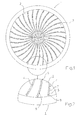
- a swirl diffuser 1 which has curved lamellae as devices 2 for influencing an air flow (arrow 3). Between two adjacent slats outlet openings 4 are provided, through which the air flows in the direction of the arrow 3 in the space to be ventilated.
- Each lamella consists of a surface element with an upstream edge 5 and with a downstream edge 6.
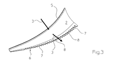
- the inflow-side edge 5 of each blade is formed in a straight line.
- downstream edge 6 has an outer contour provided with projecting projections 7 and recesses 8 located therebetween. In the illustrated embodiment, the downstream edge 6 has an approximately wave-shaped course.
- the flowing air is shown by the arrows 3.
- the edge has no rectilinear tear-off edge. This form at most small vortex rolls, which sometimes even cancel each other.
- the recesses 8 and projections 7 may of course be rounded transversely to the course of the entire edge.
- Fig. 4 is an air guide element with a total of three devices 2 for influencing an air flow in one Component of an air conditioning system shown.
- a component is a slot passage in the present case.
- the air guide is rotatably mounted about the axis R in the slot passage, not shown.
- the downstream edges 6 are provided with protruding projections 7 and recesses 8 located therebetween, wherein the projections 7 and the recesses 8 have a zigzag-shaped course.
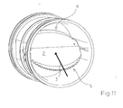
- each damper blade is provided in the Fig. 5 to 12 regulators, wherein as device 2 in each regulator a damper blade is provided.
- the Fig. 5 to 8 affect a rectangular and the Fig. 9 to 12 a round knob.
- Each damper blade is rotatably mounted in the controller about an axis D oriented transversely to the flow direction 3.
- the downstream edge 6 has an outer contour provided with protruding projections 7 and recesses 8 located therebetween.
- the upstream edge 5 is rectilinear.
- Both the inflow-side edge 5 and the outflow-side edge 6 have protrusions 7 and recesses 8 located therebetween.
- the projections 7 and the recesses 8 in an approximately zigzag-shaped course, the shape and dimensions of the projections 7 and the recesses 8 are the same.
- the shape and dimensions of the projections 7 and the recesses 8 are not equal.
- the projections 7 have a uniform absolute orientation, wherein in the illustrated embodiment, the orientation is parallel to the flow direction (arrow 3).
- the height of the projections 7 increases from the center M of each edge to the two stub shafts 9, which are provided for storage.
- the height H refers to the distance from the highest point of a projection 7 to the lowest point of the adjacent recess 8.
- the width B refers to the distance between the vertices of two adjacent projections 7 and the center distance of two adjacent projections. 7
- the device 2 is a louver of a passage (for example Fig. 1 ), 20 to 30 projections per 100 mm in length at edge 5, 6 offer.
- the device 2 as a damper blade of a controller ((for example Fig. 5 ) are preferably 25 to 40 protrusions per 100 mm in length at edge 5, 6 advantageous.
- the dimensions of the projections 7 vary in the embodiment, for example Fig. 10 over the course the edge 6, while the dimensions of the projections 7 in the embodiment, for example after Fig. 8 are continuous over the course of the respective edge 5, 6.
Landscapes
- Engineering & Computer Science (AREA)
- Chemical & Material Sciences (AREA)
- Combustion & Propulsion (AREA)
- Mechanical Engineering (AREA)
- General Engineering & Computer Science (AREA)
- Air-Flow Control Members (AREA)
- Air-Conditioning For Vehicles (AREA)
Abstract
Description
- Die Erfindung betrifft eine Einrichtung zur Beeinflussung einer Luftströmung in einer Komponente einer klimatechnischen Anlage, wobei die Einrichtung ein Flächenelement mit zumindest einer anströmseitigen und zumindest mit einer abströmseitigen Kante umfasst und wobei das Flächenelement entweder ortsfest in der Komponente angeordnet ist oder um eine parallel zur generellen Erstreckung der Ebene des Flächenelementes bzw. zur generellen Erstreckung eines Teilbereichs der Ebene des Flächenelementes ausgerichtete Achse drehbar in der Komponente gelagert ist.
- Durchlässe, wie beispielsweise Dralldurchlässe, weisen üblicherweise feststehende Lamellen auf, wobei zwei benachbarte Lamellen zwischen sich eine Auslassöffnung bilden. Die anströmseitige Kante und die abströmseitige Kante jeder Lamelle sind geradlinig ausgebildet. Da derartige Lamellen insoweit eine gerade Abrisskante aufweisen, kommt es zu einer starken Wirbelbildung, was wiederum zu einem höheren Druckverlust sowie einer unerwünschten Geräuschbildung führt.
- Aufgabe der Erfindung ist es, die vorgenannten Nachteile zu vermeiden und eine Einrichtung zur Beeinflussung einer Luftströmung anzugeben, deren Geräuschentwicklung geringer ist.
- Diese Aufgabe wird dadurch gelöst, dass zumindest eine Kante, insbesondere zumindest eine abströmseitige Kante, eine mit vorstehenden Vorsprüngen und dazwischenliegenden Vertiefungen versehene Außenkontur aufweist. Aufgrund der aus Vorsprüngen und Vertiefungen bestehenden Außenkontur weist die erfindungsgemäße Einrichtung damit keine gerade Abrisskante mehr auf. Vielmehr entstehen viele versetzt zueinander angeordnete kurze Abrisskanten. Damit können sich lediglich entsprechend kleine Wirbel bilden, die sich teilweise sogar gegenseitig aufheben. Damit wird die unerwünschte Geräuschbildung reduziert.
- Die Form und die Abmessungen wenigstens eines Vorsprungs und zumindest einer Vertiefung können gleich sein. Es ist aber auch selbstverständlich möglich, dass zumindest eine Vertiefung eine andere Ausgestaltung als ein Vorsprung aufweisen. So kann beispielsweise der Vorsprung dreieckförmig ausgebildet sein, während die Vertiefung in ihrem tiefsten Bereich flach ausgebildet ist.
- Die Vorsprünge sowie die Vertiefungen zumindest einer Kante, insbesondere zumindest einer abströmseitigen Kante, können einen wellenförmigen Verlauf aufweisen.
- Die Vorsprünge sowie die Vertiefungen zumindest einer Kante, insbesondere zumindest einer abströmseitigen Kante, können einen zick-zack-förmigen Verlauf aufweisen. Bei einer solchen Ausgestaltung sind sowohl die Vorsprünge als auch die Vertiefungen in etwa dreieckförmig ausgebildet.
- Die Vorsprünge sowie die Vertiefungen zumindest einer Kante, insbesondere zumindest einer abströmseitigen Kante, können einen rechteckförmigen Verlauf aufweisen. Bei einer solchen Ausgestaltung ist die entsprechende Kante nach Art eines Rakels ausgebildet.
- Die Vorsprünge zumindest einer Kante, insbesondere zumindest einer abströmseitigen Kante, können eine einheitliche absolute Ausrichtung aufweisen. Damit weisen die Vorsprünge und/oder die Vertiefungen eine einheitliche Ausrichtung unabhängig von dem tatsächlichen Verlauf der betreffenden Kante auf. Handelt es sich bei der Einrichtung beispielsweise um ein Lamellenblatt mit einer runden Kante, können alle Vorsprünge beispielsweise in Strömungsrichtung weisen. Bei einer solchen runden Ausgestaltung weisen die Vorsprünge untereinander dann über den Verlauf der Kante gesehen eine unterschiedliche Ausgestaltung auf.
- Es ist aber auch durchaus möglich, dass die Vorsprünge zumindest einer Kante, insbesondere zumindest einer abströmseitigen Kante, eine relative, auf einen Punkt gerichtete Ausrichtung aufweisen. Auch hier ist die Ausrichtung der Vorsprünge unabhängig von dem Verlauf der betreffenden Kante. Alle Vorsprünge können beispielsweise auf einen Mittelpunkt oder aber auf die Symmetrieachse gerichtet sein. Auch bei einer solchen Ausführungsfrom weisen die Vorsprünge der betreffenden Kante eine andere Ausgestaltung auf.
- Die Einrichtung kann als Klappenblatt ausgebildet sein. Ein entsprechendes Klappenblatt kann beispielsweise in einer Brandschutzklappe, einem Volumenstromregler, einer Drosselklappe oder dergleichen eingesetzt sein. Bei Verwendung des Lamellenblattes in einer Drosselklappe bleibt die Stellung des Klappenblattes unverändert. Demgegenüber verändert sich die Stellung des Klappenblattes beispielsweise in einem Volumenstromregler bei wechselnder Luftströmung innerhalb der klimatechnischen Anlage.
- Die Einrichtung kann auch als Lamelle, insbesondere als feststehende Lamelle, eines Durchlasses, insbesondere eines Dralldurchlasses, ausgebildet sein. Bei einem solchen Durchlass kann es sich um einen Auslass oder einen Einlass handeln.
- Zur weiteren Reduzierung von Geräuschen kann zumindest eine Vertiefung und/oder ein Vorsprung quer zum Verlauf der gesamten Kante abgerundet ausgebildet sein.
- Die Höhe H zumindest eines Vorsprungs beträgt zum tiefsten Punkt der benachbarten Vertiefung gesehen zwischen 0,5 mm und 10 mm, vorzugsweise zwischen 1 mm und 5 mm. Die Höhe H bezieht sich auf den Abstand vom höchsten Punkt des Vorsprungs bis zum tiefsten Punkt der benachbarten Vertiefung.
- Die Breite B zumindest eines Vorsprungs beträgt zwischen 1 mm und 8 mm, vorzugsweise zwischen 2 mm und 4 mm. Die Breite B bezieht sich auf den Abstand der Scheitelpunkte zweier benachbarter Vorsprünge bzw. den Mittenabstand zweier benachbarter Vorsprünge.
- Vorzugweise sind 10 bis 50 Vorsprünge pro 100 mm Länge an Kante vorgesehen. Handelt es sich bei der Einrichtung um eine Lamelle eines Durchlasses, bieten sich 20 bis 30 Vorsprünge pro 100 mm Länge an Kante an. Bei Ausgestaltung der Einrichtung als Klappenblatt sind vorzugsweise 25 bis 40 Vorsprünge pro 100 mm Länge an Kante vorteilhaft.
- Die Abmessungen der Vorsprünge können über den Verlauf einer Kante variieren, vorzugsweise bei Durchlässen, oder stetig, vorzugsweise bei Klappen, sein.
- Im Folgenden werden in den Zeichnungen dargestellte Ausführungsbeispiele der Erfindung erläutert. Es zeigen:
- Fig. 1
- eine Draufsicht auf einen Drallauslass,
- Fig. 2
- ein Detail aus
Fig. 1 , - Fig. 3
- eine erfindungsgemäße Einrichtung im Detail,
- Fig. 4
- eine erfindungsgemäße Einrichtung für Schlitzdurchlässe mit gezahnten Abströmkanten,
- Fig. 5
- einen Volumenstromregler mit einem rechteckigen, einseitig gezackten Klappenblatt,
- Fig. 6
- das Klappenblatt aus
Fig. 5 , - Fig. 7
- einen Volumenstromregler mit einem rechteckigen, beidseitig gezackten Klappenblatt,
- Fig. 8
- das Klappenblatt nach
Fig. 7 , - Fig. 9
- einen Volumenstromregler mit einem runden, einseitig gezackten Klappenblatt,
- Fig. 10
- das Klappenblatt nach
Fig. 9 , - Fig. 11
- einen Volumenstromregler mit einem runden, beidseitig gezackten Klappenblatt und
- Fig. 12
- das Klappenblatt nach
Fig. 11 . - In allen Figuren werden für gleiche bzw. gleichartige Bauteile übereinstimmende Bezugszeichen verwendet.
- In
Fig. 1 ist ein Dralldurchlass 1 dargestellt, der als Einrichtungen 2 zur Beeinflussung einer Luftströmung (Pfeil 3) geschwungen ausgebildete Lamellen aufweist. Zwischen zwei benachbarten Lamellen sind Auslassöffnungen 4 vorgesehen, durch die die Luft in Richtung des Pfeils 3 in den zu belüftenden Raum strömt. Jede Lamelle besteht aus einem Flächenelement mit einer anströmseitigen Kante 5 und mit einer abströmseitigen Kante 6. - Wie insbesondere den
Fig. 2 und3 zu entnehmen ist, ist die anströmseitige Kante 5 jeder Lamelle geradlinig ausgebildet. - Demgegenüber weist die abströmseitige Kante 6 eine mit vorstehenden Vorsprüngen 7 und dazwischen liegenden Vertiefungen 8 versehene Außenkontur auf. In dem dargestellten Ausführungsbeispiel weist die abströmseitige Kante 6 einen in etwa wellenförmigen Verlauf auf.
- Die strömende Luft ist durch die Pfeile 3 dargestellt. Infolge des wellenförmigen Verlaufs der abströmseitigen Kante 6 hat die Kante keine geradlinige Abrisskante. Damit bilden sich allenfalls kleine Wirbelwalzen, die sich teilweise sogar selbst gegeneinander aufheben. Die Vertiefungen 8 und Vorsprünge 7 können selbstverständlich quer zum Verlauf der gesamten Kante abgerundet sein.
- In
Fig. 4 ist ein Luftleitelement mit insgesamt drei Einrichtungen 2 zur Beeinflussung einer Luftströmung in einer Komponente einer klimatechnischen Anlage dargestellt. Bei einer solchen Komponente handelt es sich in dem vorliegenden Fall um einen Schlitzdurchlass. Das Luftleitelement ist drehbar um die Achse R in dem nicht dargestellten Schlitzdurchlass gelagert. WieFig. 4 zu entnehmen ist, sind die abströmseitigen Kanten 6 mit vorstehenden Vorsprüngen 7 und dazwischen liegenden Vertiefungen 8 versehen, wobei die Vorsprünge 7 sowie die Vertiefungen 8 einen zick-zack-förmigen Verlauf aufweisen. - In den
Fig. 5 bis 12 sind Regler dargestellt, wobei als Einrichtung 2 in jedem Regler ein Klappenblatt vorgesehen ist. DieFig. 5 bis 8 betreffen einen rechteckigen und dieFig. 9 bis 12 einen runden Regler. Jedes Klappenblatt ist um eine quer zur Strömungsrichtung 3 ausgerichtete Achse D drehbar in dem Regler gelagert. - Bei den Ausführungsbeispielen nach den
Fig. 5 und9 weist lediglich die abströmseitige Kante 6 eine mit vorstehenden Vorsprüngen 7 und dazwischen liegenden Vertiefungen 8 versehene Außenkontur auf. Die anströmseitige Kante 5 ist geradlinig ausgebildet. - Bei den Ausführungsbeispielen nach den
Fig. 7 und11 weisen sowohl die anströmseitige Kante 5 als auch die abströmseitige Kante 6 Vorsprünge 7 und dazwischen liegende Vertiefungen 8 auf. - Wie den
Fig. 6 und8 zu entnehmen ist, weisen die Vorsprünge 7 sowie die Vertiefungen 8 einen in etwa zick-zack-förmigen Verlauf auf, wobei die Form und die Abmessungen der Vorsprünge 7 und der Vertiefungen 8 gleich sind. - Bei den runden Ausführungsformen der Klappenblätter nach den
Fig. 10 und12 sind die Form und die Abmessungen der Vorsprünge 7 und der Vertiefungen 8 nicht gleich. So weisen die Vorsprünge 7 eine einheitliche absolute Ausrichtung auf, wobei in dem dargestellten Ausführungsbeispiel die Ausrichtung parallel zur Strömungsrichtung (Pfeil 3) ist. - Infolge dessen vergrößert sich die Höhe der Vorsprünge 7 von der Mitte M jeder Kante zu den beiden Achsstummeln 9 hin, die zur Lagerung vorgesehen sind.
- In den
Fig. 6 ,8 und10 ist beispielshaft die Höhe H der Vorsprünge 7, die zum tiefsten Punkt der benachbarten Vertiefung 8 gesehen zwischen 0,5 mm und 10 mm, beträgt, eingezeichnet. Die Höhe H bezieht sich auf den Abstand vom höchsten Punkt eines Vorsprungs 7 bis zum tiefsten Punkt der benachbarten Vertiefung 8. - Auch ist in den
Fig. 6 ,8 und10 beispielshaft die Breite B eines Vorsprungs 7, die zwischen 1 mm und 8 mm beträgt, eingezeichnet. Die Breite B bezieht sich auf den Abstand der Scheitelpunkte zweier benachbarter Vorsprünge 7 bzw. den Mittenabstand zweier benachbarter Vorsprünge 7. - Handelt es sich bei der Einrichtung 2 um eine Lamelle eines Durchlasses (beispielsweise
Fig. 1 ), bieten sich 20 bis 30 Vorsprünge pro 100 mm Länge an Kante 5, 6 an. Bei Ausgestaltung der Einrichtung 2 als Klappenblatt eines Reglers ((beispielsweiseFig. 5 ) sind vorzugsweise 25 bis 40 Vorsprünge pro 100 mm Länge an Kante 5, 6 vorteilhaft. - Die Abmessungen der Vorsprünge 7 variieren bei dem Ausführungsbeispiel beispielsweise nach
Fig. 10 über den Verlauf der Kante 6, während die Abmessungen der Vorsprünge 7 bei dem Ausführungsbeispiel beispielsweise nachFig. 8 über den Verlauf der jeweiligen Kante 5, 6 stetig sind.
Claims (13)
- Einrichtung (2) zur Beeinflussung einer Luftströmung (3) in einer Komponente (1) einer klimatechnischen Anlage, wobei die Einrichtung (2) ein Flächenelement mit zumindest einer anströmseitigen und zumindest mit einer abströmseitigen Kante (5, 6) umfasst und wobei das Flächenelement entweder ortsfest in der Komponente (1) angeordnet ist oder um eine parallel zur generellen Erstreckung der Ebene des Flächenelementes bzw. zur generellen Erstreckung eines Teilbereichs der Ebene des Flächenelementes ausgerichtete Achse (R, D) drehbar in der Komponente (1) gelagert ist, dadurch gekennzeichnet, dass zumindest eine Kante (5, 6), insbesondere zumindest eine abströmseitige Kante (6), eine mit vorstehenden Vorsprüngen (7) und dazwischenliegenden Vertiefungen (8) versehene Außenkontur aufweist.
- Einrichtung (2) nach dem vorhergehenden Anspruch, dadurch gekennzeichnet, dass die Form und die Abmessungen wenigstens eines Vorsprungs (7) und zumindest einer Vertiefung (8) gleich sind.
- Einrichtung (2) nach einem der vorhergehenden Ansprüche, dadurch gekennzeichnet, dass die Vorsprünge (7) sowie die Vertiefungen (8) zumindest einer Kante (5, 6), insbesondere zumindest einer abströmseitigen Kante (6), einen wellenförmigen Verlauf aufweisen.
- Einrichtung (2) nach einem der vorhergehenden Ansprüche, dadurch gekennzeichnet, dass die Vorsprünge (7) sowie die Vertiefungen (8) zumindest einer Kante (5, 6), insbesondere zumindest einer abströmseitigen Kante (6), einen zick-zack-förmigen Verlauf aufweisen.
- Einrichtung (2) nach einem der vorhergehenden Ansprüche, dadurch gekennzeichnet, dass die Vorsprünge (7) sowie die Vertiefungen (8) zumindest einer Kante (5, 6), insbesondere zumindest einer abströmseitigen Kante (6), einen rechteckförmigen Verlauf aufweisen.
- Einrichtung (2) nach einem der vorhergehenden Ansprüche, dadurch gekennzeichnet, dass die Vorsprünge (7) zumindest einer Kante (5, 6), insbesondere zumindest einer abströmseitigen Kante (6), eine einheitliche absolute Ausrichtung aufweisen.
- Einrichtung (2) nach einem der vorhergehenden Ansprüche, dadurch gekennzeichnet, dass die Vorsprünge (7) zumindest einer Kante (5, 6), insbesondere zumindest einer abströmseitigen Kante (6), eine relative, auf einen Punkt gerichtete Ausrichtung aufweisen.
- Einrichtung (2) nach einem der vorhergehenden Ansprüche, dadurch gekennzeichnet, dass die Einrichtung (2) als Klappenblatt ausgebildet ist.
- Einrichtung (2) nach einem der vorhergehenden Ansprüche, dadurch gekennzeichnet, dass die Einrichtung (2) als Lamelle, insbesondere als feststehende Lamelle, eines Durchlasses, insbesondere eines Dralldurchlasses (1), ausgebildet ist.
- Einrichtung (2) nach einem der vorhergehenden Ansprüche, dadurch gekennzeichnet, dass zumindest eine Vertiefung (8) und/oder ein Vorsprung (7) quer zum Verlauf der gesamten Kante (5, 6) abgerundet ausgebildet ist.
- Einrichtung (2) nach einem der vorhergehenden Ansprüche, dadurch gekennzeichnet, dass die Höhe H zumindest eines Vorsprungs (7) zum tiefsten Punkt der benachbarten Vertiefung (8) gesehen zwischen 0,5 mm und 10 mm, vorzugsweise zwischen 1 mm und 5 mm, beträgt.
- Einrichtung (2) nach einem der vorhergehenden Ansprüche, dadurch gekennzeichnet, dass die Breite B zumindest eines Vorsprungs (7) zwischen 1 mm und 8 mm, vorzugsweise zwischen 2 mm und 4 mm, beträgt.
- Einrichtung (2) nach einem der vorhergehenden Ansprüche, dadurch gekennzeichnet, dass vorzugweise 10 bis 50 Vorsprünge (7) pro 100 mm Länge an Kante (5, 6) vorgesehen sind.
Priority Applications (3)
| Application Number | Priority Date | Filing Date | Title |
|---|---|---|---|
| EP11161712.2A EP2508815B1 (de) | 2011-04-08 | 2011-04-08 | Einrichtung zur Beeinflussung einer Luftströmung in einer Komponente einer klimatechnischen Anlage |
| DK11161712.2T DK2508815T3 (da) | 2011-04-08 | 2011-04-08 | Indretning til påvirkning af en luftstrømning i en komponent af et klimateknisk anlæg |
| ES11161712T ES2788099T3 (es) | 2011-04-08 | 2011-04-08 | Dispositivo para influir sobre un flujo de aire en un componente de una instalación de climatización |
Applications Claiming Priority (1)
| Application Number | Priority Date | Filing Date | Title |
|---|---|---|---|
| EP11161712.2A EP2508815B1 (de) | 2011-04-08 | 2011-04-08 | Einrichtung zur Beeinflussung einer Luftströmung in einer Komponente einer klimatechnischen Anlage |
Publications (2)
| Publication Number | Publication Date |
|---|---|
| EP2508815A1 true EP2508815A1 (de) | 2012-10-10 |
| EP2508815B1 EP2508815B1 (de) | 2020-02-12 |
Family
ID=44511816
Family Applications (1)
| Application Number | Title | Priority Date | Filing Date |
|---|---|---|---|
| EP11161712.2A Active EP2508815B1 (de) | 2011-04-08 | 2011-04-08 | Einrichtung zur Beeinflussung einer Luftströmung in einer Komponente einer klimatechnischen Anlage |
Country Status (3)
| Country | Link |
|---|---|
| EP (1) | EP2508815B1 (de) |
| DK (1) | DK2508815T3 (de) |
| ES (1) | ES2788099T3 (de) |
Cited By (14)
| Publication number | Priority date | Publication date | Assignee | Title |
|---|---|---|---|---|
| CN105953309A (zh) * | 2016-05-30 | 2016-09-21 | 重庆大学 | 一种高原专用的风机盘管机组 |
| CN107420984A (zh) * | 2017-06-23 | 2017-12-01 | 青岛海尔空调器有限总公司 | 具有摆叶的空调室内机及确定室内机摆叶的方法 |
| EP3409994A1 (de) * | 2017-06-02 | 2018-12-05 | Zehnder Group International AG | Rohreinsatz und system mit rohreinsatz |
| WO2019143863A1 (en) * | 2018-01-17 | 2019-07-25 | Johnson Controls, Inc. | Air damper |
| US10768031B2 (en) | 2018-01-17 | 2020-09-08 | Johnson Controls, Inc. | Air duct airflow sensor |
| EP3992539A3 (de) * | 2020-11-02 | 2022-08-17 | Monodraught Limited | Belüftungsvorrichtungen |
| US11435111B2 (en) | 2019-03-11 | 2022-09-06 | Air Distribution Technologies Ip, Llc | Undulated surface enhancement of diffuser blades for round and rectangular ceiling diffuser |
| US11441811B2 (en) | 2019-03-11 | 2022-09-13 | Air Distribution Technologies Ip, Llc | Undulated surface enhancement of diffuser blade for plenum slot diffuser |
| US11448420B2 (en) | 2018-01-17 | 2022-09-20 | Johnson Controls, Inc. | Air duct damper |
| US11448418B2 (en) | 2019-03-11 | 2022-09-20 | Air Distribution Technologies Ip, Llc | Undulated surface enhancement of diffuser blades for linear bar diffuser |
| USD1014731S1 (en) | 2019-01-17 | 2024-02-13 | Johnson Controls Tyco IP Holdings LLP | Damper |
| US12038185B2 (en) | 2018-01-17 | 2024-07-16 | Tyco Fire & Security Gmbh | Air duct assembly with field accessible ports in communication with a pressure source and pressure sensing ports in communication with a pressure sensor |
| US12372270B2 (en) | 2018-01-17 | 2025-07-29 | Air Distribution Technologies Ip, Llc | Air duct damper and installation components |
| US12385768B2 (en) | 2022-08-31 | 2025-08-12 | Tyco Fire & Security Gmbh | Air duct airflow sensor |
Citations (5)
| Publication number | Priority date | Publication date | Assignee | Title |
|---|---|---|---|---|
| EP0690272A2 (de) * | 1994-07-01 | 1996-01-03 | Draftex Industries Limited | Gas- oder Luftdurchflussregler |
| DE19717335A1 (de) * | 1996-05-06 | 1997-11-20 | Valeo Climatisation | Schwenkklappe mit Dichtungslippe für Lüftungsvorrichtung |
| EP0884542A1 (de) * | 1996-12-16 | 1998-12-16 | Daikin Industries, Limited | Ausseneinheit für klimaanlage |
| EP0905455A1 (de) * | 1997-04-02 | 1999-03-31 | Daikin Industries, Limited | Ausseneinheit für klimaanlage mit getrennten geräten |
| DE102007016184A1 (de) * | 2007-04-02 | 2008-10-09 | Behr Gmbh & Co. Kg | Klappenanordnung, insbesondere für ein Kraftfahrzeug-Belüftungssystem |
-
2011
- 2011-04-08 ES ES11161712T patent/ES2788099T3/es active Active
- 2011-04-08 DK DK11161712.2T patent/DK2508815T3/da active
- 2011-04-08 EP EP11161712.2A patent/EP2508815B1/de active Active
Patent Citations (5)
| Publication number | Priority date | Publication date | Assignee | Title |
|---|---|---|---|---|
| EP0690272A2 (de) * | 1994-07-01 | 1996-01-03 | Draftex Industries Limited | Gas- oder Luftdurchflussregler |
| DE19717335A1 (de) * | 1996-05-06 | 1997-11-20 | Valeo Climatisation | Schwenkklappe mit Dichtungslippe für Lüftungsvorrichtung |
| EP0884542A1 (de) * | 1996-12-16 | 1998-12-16 | Daikin Industries, Limited | Ausseneinheit für klimaanlage |
| EP0905455A1 (de) * | 1997-04-02 | 1999-03-31 | Daikin Industries, Limited | Ausseneinheit für klimaanlage mit getrennten geräten |
| DE102007016184A1 (de) * | 2007-04-02 | 2008-10-09 | Behr Gmbh & Co. Kg | Klappenanordnung, insbesondere für ein Kraftfahrzeug-Belüftungssystem |
Cited By (21)
| Publication number | Priority date | Publication date | Assignee | Title |
|---|---|---|---|---|
| CN105953309A (zh) * | 2016-05-30 | 2016-09-21 | 重庆大学 | 一种高原专用的风机盘管机组 |
| EP3409994A1 (de) * | 2017-06-02 | 2018-12-05 | Zehnder Group International AG | Rohreinsatz und system mit rohreinsatz |
| WO2018220604A1 (de) * | 2017-06-02 | 2018-12-06 | Zehnder Group International Ag | Rohreinsatz und system mit rohreinsatz |
| CN107420984A (zh) * | 2017-06-23 | 2017-12-01 | 青岛海尔空调器有限总公司 | 具有摆叶的空调室内机及确定室内机摆叶的方法 |
| WO2018233671A1 (zh) * | 2017-06-23 | 2018-12-27 | 青岛海尔空调器有限总公司 | 具有摆叶的空调室内机 |
| US10768031B2 (en) | 2018-01-17 | 2020-09-08 | Johnson Controls, Inc. | Air duct airflow sensor |
| WO2019143863A1 (en) * | 2018-01-17 | 2019-07-25 | Johnson Controls, Inc. | Air damper |
| CN112136008A (zh) * | 2018-01-17 | 2020-12-25 | 江森自控股份有限公司 | 空气闸 |
| US12372270B2 (en) | 2018-01-17 | 2025-07-29 | Air Distribution Technologies Ip, Llc | Air duct damper and installation components |
| US12038185B2 (en) | 2018-01-17 | 2024-07-16 | Tyco Fire & Security Gmbh | Air duct assembly with field accessible ports in communication with a pressure source and pressure sensing ports in communication with a pressure sensor |
| US12025335B2 (en) | 2018-01-17 | 2024-07-02 | Johnson Controls, Inc. | Air duct damper |
| US11448420B2 (en) | 2018-01-17 | 2022-09-20 | Johnson Controls, Inc. | Air duct damper |
| US12000721B2 (en) | 2018-01-17 | 2024-06-04 | Tyco Fire & Security Gmbh | Air duct airflow sensor with internal low-pressure detector |
| US20220390145A1 (en) * | 2018-01-17 | 2022-12-08 | Johnson Controls, Inc. | Air duct damper |
| CN116447739A (zh) * | 2018-01-17 | 2023-07-18 | 江森自控泰科知识产权控股有限责任合伙公司 | 空气闸 |
| USD1014731S1 (en) | 2019-01-17 | 2024-02-13 | Johnson Controls Tyco IP Holdings LLP | Damper |
| US11448418B2 (en) | 2019-03-11 | 2022-09-20 | Air Distribution Technologies Ip, Llc | Undulated surface enhancement of diffuser blades for linear bar diffuser |
| US11441811B2 (en) | 2019-03-11 | 2022-09-13 | Air Distribution Technologies Ip, Llc | Undulated surface enhancement of diffuser blade for plenum slot diffuser |
| US11435111B2 (en) | 2019-03-11 | 2022-09-06 | Air Distribution Technologies Ip, Llc | Undulated surface enhancement of diffuser blades for round and rectangular ceiling diffuser |
| EP3992539A3 (de) * | 2020-11-02 | 2022-08-17 | Monodraught Limited | Belüftungsvorrichtungen |
| US12385768B2 (en) | 2022-08-31 | 2025-08-12 | Tyco Fire & Security Gmbh | Air duct airflow sensor |
Also Published As
| Publication number | Publication date |
|---|---|
| EP2508815B1 (de) | 2020-02-12 |
| DK2508815T3 (da) | 2020-05-11 |
| ES2788099T3 (es) | 2020-10-20 |
Similar Documents
| Publication | Publication Date | Title |
|---|---|---|
| EP2508815B1 (de) | Einrichtung zur Beeinflussung einer Luftströmung in einer Komponente einer klimatechnischen Anlage | |
| DE102009007037A1 (de) | Ausströmdüse einer Belüftungsvorrichtung oder Klimaanlage für Fahrzeuge | |
| WO2009019264A2 (de) | Ausströmventil für ein luftfahrzeug | |
| DE10292792T5 (de) | Klimatisierungskanal für ein Fahrzeug | |
| EP2322866B9 (de) | Drallauslass zur Belüftung von Räumen | |
| EP2185884B1 (de) | Rippe für einen wärmetauscher | |
| DE102018109985B4 (de) | Verschlussvorrichtung mit Leitschaufel | |
| EP1812167B1 (de) | Strahlaustrittselement für sanitärarmaturen | |
| EP3236173B1 (de) | Verfahren zum klimatisieren eines raums | |
| DE19733319A1 (de) | Heizungs- oder Klimagerät mit einer Vorrichtung zur Luftleitung und Luftgleichrichtung | |
| EP2619022B1 (de) | Mischelement und mischmodul für zwei sich in einem klimagerät kreuzende luftströme | |
| DE69107821T2 (de) | Vorrichtung zur Erzeugung oder Messung einer Druckdifferenz. | |
| EP2498016A1 (de) | Volumenstromstelleinrichtung sowie lufttechnische Vorrichtung zum Belüften, Heizen und/oder Kühlen eines Raumes eines Gebäudes | |
| DE102007016184A1 (de) | Klappenanordnung, insbesondere für ein Kraftfahrzeug-Belüftungssystem | |
| DE4142757C2 (de) | Drosselvorrichtung | |
| DE102005010962B4 (de) | Luftdurchlass für eine lufttechnische Anlage, insbesondere Deckenauslass | |
| DE19529311C1 (de) | Auslaßdüsenleiste und Verfahren zum räumlichen Verteilen eines strömenden Mediums | |
| DE102013206873A1 (de) | Lüftungsdüse | |
| DE102014221580B4 (de) | Steuerbare Luftauslassdüse | |
| DE102005008330B4 (de) | Luftverteiler für eine Heizungs- und/oder Klimaanlage in Fahrzeugen | |
| DE102013213031A1 (de) | Stutzen | |
| WO2005012013A1 (de) | Lüftungskanal für eine innenraumbelüftung | |
| EP2604324A1 (de) | Kanalschwebstofffilter zur Filterung eines strömenden Gases | |
| EP2365200B1 (de) | Klappenventil | |
| EP1481830B1 (de) | Belüftungsvorrichtung, insbesondere für ein Kraftfahrzeug |
Legal Events
| Date | Code | Title | Description |
|---|---|---|---|
| PUAI | Public reference made under article 153(3) epc to a published international application that has entered the european phase |
Free format text: ORIGINAL CODE: 0009012 |
|
| AK | Designated contracting states |
Kind code of ref document: A1 Designated state(s): AL AT BE BG CH CY CZ DE DK EE ES FI FR GB GR HR HU IE IS IT LI LT LU LV MC MK MT NL NO PL PT RO RS SE SI SK SM TR |
|
| AX | Request for extension of the european patent |
Extension state: BA ME |
|
| 17P | Request for examination filed |
Effective date: 20130409 |
|
| 17Q | First examination report despatched |
Effective date: 20141013 |
|
| STAA | Information on the status of an ep patent application or granted ep patent |
Free format text: STATUS: EXAMINATION IS IN PROGRESS |
|
| GRAP | Despatch of communication of intention to grant a patent |
Free format text: ORIGINAL CODE: EPIDOSNIGR1 |
|
| STAA | Information on the status of an ep patent application or granted ep patent |
Free format text: STATUS: GRANT OF PATENT IS INTENDED |
|
| INTG | Intention to grant announced |
Effective date: 20191007 |
|
| GRAS | Grant fee paid |
Free format text: ORIGINAL CODE: EPIDOSNIGR3 |
|
| GRAA | (expected) grant |
Free format text: ORIGINAL CODE: 0009210 |
|
| STAA | Information on the status of an ep patent application or granted ep patent |
Free format text: STATUS: THE PATENT HAS BEEN GRANTED |
|
| AK | Designated contracting states |
Kind code of ref document: B1 Designated state(s): AL AT BE BG CH CY CZ DE DK EE ES FI FR GB GR HR HU IE IS IT LI LT LU LV MC MK MT NL NO PL PT RO RS SE SI SK SM TR |
|
| REG | Reference to a national code |
Ref country code: GB Ref legal event code: FG4D Free format text: NOT ENGLISH |
|
| REG | Reference to a national code |
Ref country code: CH Ref legal event code: EP |
|
| REG | Reference to a national code |
Ref country code: AT Ref legal event code: REF Ref document number: 1232633 Country of ref document: AT Kind code of ref document: T Effective date: 20200215 |
|
| REG | Reference to a national code |
Ref country code: DE Ref legal event code: R096 Ref document number: 502011016440 Country of ref document: DE |
|
| REG | Reference to a national code |
Ref country code: IE Ref legal event code: FG4D Free format text: LANGUAGE OF EP DOCUMENT: GERMAN |
|
| REG | Reference to a national code |
Ref country code: DK Ref legal event code: T3 Effective date: 20200506 |
|
| REG | Reference to a national code |
Ref country code: NL Ref legal event code: FP |
|
| PG25 | Lapsed in a contracting state [announced via postgrant information from national office to epo] |
Ref country code: NO Free format text: LAPSE BECAUSE OF FAILURE TO SUBMIT A TRANSLATION OF THE DESCRIPTION OR TO PAY THE FEE WITHIN THE PRESCRIBED TIME-LIMIT Effective date: 20200512 Ref country code: FI Free format text: LAPSE BECAUSE OF FAILURE TO SUBMIT A TRANSLATION OF THE DESCRIPTION OR TO PAY THE FEE WITHIN THE PRESCRIBED TIME-LIMIT Effective date: 20200212 Ref country code: RS Free format text: LAPSE BECAUSE OF FAILURE TO SUBMIT A TRANSLATION OF THE DESCRIPTION OR TO PAY THE FEE WITHIN THE PRESCRIBED TIME-LIMIT Effective date: 20200212 |
|
| REG | Reference to a national code |
Ref country code: LT Ref legal event code: MG4D |
|
| PG25 | Lapsed in a contracting state [announced via postgrant information from national office to epo] |
Ref country code: HR Free format text: LAPSE BECAUSE OF FAILURE TO SUBMIT A TRANSLATION OF THE DESCRIPTION OR TO PAY THE FEE WITHIN THE PRESCRIBED TIME-LIMIT Effective date: 20200212 Ref country code: GR Free format text: LAPSE BECAUSE OF FAILURE TO SUBMIT A TRANSLATION OF THE DESCRIPTION OR TO PAY THE FEE WITHIN THE PRESCRIBED TIME-LIMIT Effective date: 20200513 Ref country code: LV Free format text: LAPSE BECAUSE OF FAILURE TO SUBMIT A TRANSLATION OF THE DESCRIPTION OR TO PAY THE FEE WITHIN THE PRESCRIBED TIME-LIMIT Effective date: 20200212 Ref country code: SE Free format text: LAPSE BECAUSE OF FAILURE TO SUBMIT A TRANSLATION OF THE DESCRIPTION OR TO PAY THE FEE WITHIN THE PRESCRIBED TIME-LIMIT Effective date: 20200212 Ref country code: IS Free format text: LAPSE BECAUSE OF FAILURE TO SUBMIT A TRANSLATION OF THE DESCRIPTION OR TO PAY THE FEE WITHIN THE PRESCRIBED TIME-LIMIT Effective date: 20200612 Ref country code: BG Free format text: LAPSE BECAUSE OF FAILURE TO SUBMIT A TRANSLATION OF THE DESCRIPTION OR TO PAY THE FEE WITHIN THE PRESCRIBED TIME-LIMIT Effective date: 20200512 |
|
| REG | Reference to a national code |
Ref country code: ES Ref legal event code: FG2A Ref document number: 2788099 Country of ref document: ES Kind code of ref document: T3 Effective date: 20201020 |
|
| PG25 | Lapsed in a contracting state [announced via postgrant information from national office to epo] |
Ref country code: LT Free format text: LAPSE BECAUSE OF FAILURE TO SUBMIT A TRANSLATION OF THE DESCRIPTION OR TO PAY THE FEE WITHIN THE PRESCRIBED TIME-LIMIT Effective date: 20200212 Ref country code: CZ Free format text: LAPSE BECAUSE OF FAILURE TO SUBMIT A TRANSLATION OF THE DESCRIPTION OR TO PAY THE FEE WITHIN THE PRESCRIBED TIME-LIMIT Effective date: 20200212 Ref country code: RO Free format text: LAPSE BECAUSE OF FAILURE TO SUBMIT A TRANSLATION OF THE DESCRIPTION OR TO PAY THE FEE WITHIN THE PRESCRIBED TIME-LIMIT Effective date: 20200212 Ref country code: PT Free format text: LAPSE BECAUSE OF FAILURE TO SUBMIT A TRANSLATION OF THE DESCRIPTION OR TO PAY THE FEE WITHIN THE PRESCRIBED TIME-LIMIT Effective date: 20200705 Ref country code: SK Free format text: LAPSE BECAUSE OF FAILURE TO SUBMIT A TRANSLATION OF THE DESCRIPTION OR TO PAY THE FEE WITHIN THE PRESCRIBED TIME-LIMIT Effective date: 20200212 Ref country code: SM Free format text: LAPSE BECAUSE OF FAILURE TO SUBMIT A TRANSLATION OF THE DESCRIPTION OR TO PAY THE FEE WITHIN THE PRESCRIBED TIME-LIMIT Effective date: 20200212 Ref country code: EE Free format text: LAPSE BECAUSE OF FAILURE TO SUBMIT A TRANSLATION OF THE DESCRIPTION OR TO PAY THE FEE WITHIN THE PRESCRIBED TIME-LIMIT Effective date: 20200212 |
|
| REG | Reference to a national code |
Ref country code: DE Ref legal event code: R097 Ref document number: 502011016440 Country of ref document: DE |
|
| PG25 | Lapsed in a contracting state [announced via postgrant information from national office to epo] |
Ref country code: MC Free format text: LAPSE BECAUSE OF FAILURE TO SUBMIT A TRANSLATION OF THE DESCRIPTION OR TO PAY THE FEE WITHIN THE PRESCRIBED TIME-LIMIT Effective date: 20200212 |
|
| PLBE | No opposition filed within time limit |
Free format text: ORIGINAL CODE: 0009261 |
|
| STAA | Information on the status of an ep patent application or granted ep patent |
Free format text: STATUS: NO OPPOSITION FILED WITHIN TIME LIMIT |
|
| 26N | No opposition filed |
Effective date: 20201113 |
|
| PG25 | Lapsed in a contracting state [announced via postgrant information from national office to epo] |
Ref country code: LU Free format text: LAPSE BECAUSE OF NON-PAYMENT OF DUE FEES Effective date: 20200408 |
|
| REG | Reference to a national code |
Ref country code: BE Ref legal event code: MM Effective date: 20200430 |
|
| PG25 | Lapsed in a contracting state [announced via postgrant information from national office to epo] |
Ref country code: PL Free format text: LAPSE BECAUSE OF FAILURE TO SUBMIT A TRANSLATION OF THE DESCRIPTION OR TO PAY THE FEE WITHIN THE PRESCRIBED TIME-LIMIT Effective date: 20200212 Ref country code: BE Free format text: LAPSE BECAUSE OF NON-PAYMENT OF DUE FEES Effective date: 20200430 Ref country code: SI Free format text: LAPSE BECAUSE OF FAILURE TO SUBMIT A TRANSLATION OF THE DESCRIPTION OR TO PAY THE FEE WITHIN THE PRESCRIBED TIME-LIMIT Effective date: 20200212 |
|
| PG25 | Lapsed in a contracting state [announced via postgrant information from national office to epo] |
Ref country code: IE Free format text: LAPSE BECAUSE OF NON-PAYMENT OF DUE FEES Effective date: 20200408 |
|
| PG25 | Lapsed in a contracting state [announced via postgrant information from national office to epo] |
Ref country code: TR Free format text: LAPSE BECAUSE OF FAILURE TO SUBMIT A TRANSLATION OF THE DESCRIPTION OR TO PAY THE FEE WITHIN THE PRESCRIBED TIME-LIMIT Effective date: 20200212 Ref country code: MT Free format text: LAPSE BECAUSE OF FAILURE TO SUBMIT A TRANSLATION OF THE DESCRIPTION OR TO PAY THE FEE WITHIN THE PRESCRIBED TIME-LIMIT Effective date: 20200212 Ref country code: CY Free format text: LAPSE BECAUSE OF FAILURE TO SUBMIT A TRANSLATION OF THE DESCRIPTION OR TO PAY THE FEE WITHIN THE PRESCRIBED TIME-LIMIT Effective date: 20200212 |
|
| PG25 | Lapsed in a contracting state [announced via postgrant information from national office to epo] |
Ref country code: MK Free format text: LAPSE BECAUSE OF FAILURE TO SUBMIT A TRANSLATION OF THE DESCRIPTION OR TO PAY THE FEE WITHIN THE PRESCRIBED TIME-LIMIT Effective date: 20200212 Ref country code: AL Free format text: LAPSE BECAUSE OF FAILURE TO SUBMIT A TRANSLATION OF THE DESCRIPTION OR TO PAY THE FEE WITHIN THE PRESCRIBED TIME-LIMIT Effective date: 20200212 |
|
| P01 | Opt-out of the competence of the unified patent court (upc) registered |
Effective date: 20230517 |
|
| REG | Reference to a national code |
Ref country code: DE Ref legal event code: R081 Ref document number: 502011016440 Country of ref document: DE Owner name: TROX SE, DE Free format text: FORMER OWNER: TROX GMBH, 47506 NEUKIRCHEN-VLUYN, DE |
|
| PGFP | Annual fee paid to national office [announced via postgrant information from national office to epo] |
Ref country code: NL Payment date: 20250422 Year of fee payment: 15 |
|
| PGFP | Annual fee paid to national office [announced via postgrant information from national office to epo] |
Ref country code: DE Payment date: 20250404 Year of fee payment: 15 |
|
| PGFP | Annual fee paid to national office [announced via postgrant information from national office to epo] |
Ref country code: ES Payment date: 20250519 Year of fee payment: 15 Ref country code: DK Payment date: 20250423 Year of fee payment: 15 |
|
| PGFP | Annual fee paid to national office [announced via postgrant information from national office to epo] |
Ref country code: IT Payment date: 20250430 Year of fee payment: 15 |
|
| PGFP | Annual fee paid to national office [announced via postgrant information from national office to epo] |
Ref country code: FR Payment date: 20250422 Year of fee payment: 15 |
|
| PGFP | Annual fee paid to national office [announced via postgrant information from national office to epo] |
Ref country code: CH Payment date: 20250423 Year of fee payment: 15 |
|
| PGFP | Annual fee paid to national office [announced via postgrant information from national office to epo] |
Ref country code: AT Payment date: 20250416 Year of fee payment: 15 |
|
| PGFP | Annual fee paid to national office [announced via postgrant information from national office to epo] |
Ref country code: GB Payment date: 20260327 Year of fee payment: 16 |
|
| REG | Reference to a national code |
Ref country code: CH Ref legal event code: U11 Free format text: ST27 STATUS EVENT CODE: U-0-0-U10-U11 (AS PROVIDED BY THE NATIONAL OFFICE) Effective date: 20260501 |