EP2508086A1 - Device for conveying a rod, measuring assembly with same and rod production machine with rod conveying device and/or measuring assembly - Google Patents
Device for conveying a rod, measuring assembly with same and rod production machine with rod conveying device and/or measuring assembly Download PDFInfo
- Publication number
- EP2508086A1 EP2508086A1 EP12163392A EP12163392A EP2508086A1 EP 2508086 A1 EP2508086 A1 EP 2508086A1 EP 12163392 A EP12163392 A EP 12163392A EP 12163392 A EP12163392 A EP 12163392A EP 2508086 A1 EP2508086 A1 EP 2508086A1
- Authority
- EP
- European Patent Office
- Prior art keywords
- strand
- guide
- guiding device
- measuring
- format
- Prior art date
- Legal status (The legal status is an assumption and is not a legal conclusion. Google has not performed a legal analysis and makes no representation as to the accuracy of the status listed.)
- Granted
Links
- 238000004519 manufacturing process Methods 0.000 title claims description 13
- 230000007246 mechanism Effects 0.000 claims abstract description 25
- 241000208125 Nicotiana Species 0.000 claims description 14
- 235000002637 Nicotiana tabacum Nutrition 0.000 claims description 14
- 238000012545 processing Methods 0.000 claims description 14
- 238000003860 storage Methods 0.000 claims description 4
- 230000000284 resting effect Effects 0.000 abstract 1
- 239000000463 material Substances 0.000 description 8
- 238000011161 development Methods 0.000 description 5
- 230000018109 developmental process Effects 0.000 description 5
- 238000005259 measurement Methods 0.000 description 5
- 238000013461 design Methods 0.000 description 3
- 238000003754 machining Methods 0.000 description 3
- 239000000203 mixture Substances 0.000 description 3
- 230000003287 optical effect Effects 0.000 description 3
- 230000006978 adaptation Effects 0.000 description 2
- 230000001914 calming effect Effects 0.000 description 2
- 238000004140 cleaning Methods 0.000 description 2
- 238000007689 inspection Methods 0.000 description 2
- 230000001360 synchronised effect Effects 0.000 description 2
- 238000006243 chemical reaction Methods 0.000 description 1
- 235000019504 cigarettes Nutrition 0.000 description 1
- 238000005520 cutting process Methods 0.000 description 1
- 238000005516 engineering process Methods 0.000 description 1
- 238000011156 evaluation Methods 0.000 description 1
- 238000000034 method Methods 0.000 description 1
- 230000010355 oscillation Effects 0.000 description 1
- 238000007665 sagging Methods 0.000 description 1
- 238000012360 testing method Methods 0.000 description 1
- 235000019505 tobacco product Nutrition 0.000 description 1
- 238000012549 training Methods 0.000 description 1
- 238000011144 upstream manufacturing Methods 0.000 description 1
Images


Classifications
-
- A—HUMAN NECESSITIES
- A24—TOBACCO; CIGARS; CIGARETTES; SIMULATED SMOKING DEVICES; SMOKERS' REQUISITES
- A24C—MACHINES FOR MAKING CIGARS OR CIGARETTES
- A24C5/00—Making cigarettes; Making tipping materials for, or attaching filters or mouthpieces to, cigars or cigarettes
- A24C5/32—Separating, ordering, counting or examining cigarettes; Regulating the feeding of tobacco according to rod or cigarette condition
- A24C5/34—Examining cigarettes or the rod, e.g. for regulating the feeding of tobacco; Removing defective cigarettes
-
- A—HUMAN NECESSITIES
- A24—TOBACCO; CIGARS; CIGARETTES; SIMULATED SMOKING DEVICES; SMOKERS' REQUISITES
- A24C—MACHINES FOR MAKING CIGARS OR CIGARETTES
- A24C5/00—Making cigarettes; Making tipping materials for, or attaching filters or mouthpieces to, cigars or cigarettes
- A24C5/14—Machines of the continuous-rod type
Definitions
- the invention relates to a strand guiding device, designed and arranged for guiding strands of the tobacco processing industry, comprising a housing having at least one strand passageway extending through the housing, wherein within the or each strand passage channel a format guide for the strand to be led is arranged.
- the invention relates to a measuring arrangement, designed and adapted for measuring strands of the tobacco processing industry, comprising a measuring head with at least one measuring station, wherein within the measuring head at least one strand passage channel is formed and the measuring head is assigned at least one strand guiding device for the strand to be measured ,
- the invention also relates to a strand production machine for producing strands of the tobacco processing industry with a strand guiding device and / or a measuring arrangement.
- Such strand guiding devices are used in the tobacco processing industry to guide strands, that is, endless strands or strand sections of tobacco, blends of tobacco, filter material or other materials and blends of materials suitable for making cigarettes, cigarillos or the like.
- the strands and strand sections are subject to vibrations due to their length or externally applied loads, for example due to transport or other machining operations, such as the cutting operations for separating the strands into strand sections.
- These vibrations and / or the sagging of a poorly routed strand will cause it to be subject to additional stresses and will tend to fracture, particularly due to the high speeds at which the strands and strand sections are transported.
- the strand guiding device usually comprises a format guide, which is known to be a format part which is closely tolerated with respect to its inner diameter with respect to the outer diameter of the strand to be transported and conveyed, so that the strand guided and transported in the format part lies in the format part with little play or play.
- a format guide which is known to be a format part which is closely tolerated with respect to its inner diameter with respect to the outer diameter of the strand to be transported and conveyed, so that the strand guided and transported in the format part lies in the format part with little play or play.
- Each usually permanently installed format part is in each case designed for a format, ie a strand diameter.
- the guiding of the strands or strand sections is particularly important in measuring arrangements of the type mentioned at the beginning, since inaccurate guidance and the oscillation of the strands or strand sections lead to inaccurate measurement results.
- the stations upstream and / or downstream of the measuring station initiate vibrations on the strand for the purpose of carrying out different machining operations and the transport itself, which vibrations lead to a negative influence on the measurement results.
- the measuring arrangement has a guide, by means of which the vibrations are at least partially suppressed. More precisely, a strand guiding device is associated with the measuring head, by means of which the strand is calmed and guided.
- a measuring arrangement with a strand guiding device or a strand production machine with a strand guiding device and / or a measuring arrangement strands or strand sections of different formats should be guided, measured and produced.
- a brand change usually requires the adaptation of the format guide to a changed diameter of the strand.
- the measuring arrangement for example, the density of the strand, the nature and / or composition of the strand, the envelope or other parameters can be measured by optical measuring systems, by infrared technology or by other conventional measuring methods and measuring systems by means of the or each measuring station.
- the document DE 1 180 662 discloses a strand guiding apparatus having the features of the preamble of claim 1.
- the format guide described therein is formed by a ring made of deformable material.
- This ring is pressurized axially by means of an adjustable element, wherein the pressure changes lead to a change in the cross section of the ring.
- this constructive solution involves a number of disadvantages that stand in the way of an exact measurement.
- the ring of deformable material ensures insufficient centering, since the center can move through the change of the guide cross-section of the ring.
- the center of the guide ring is not reproducibly adjustable, which leads to measurement inaccuracies.
- the desired high measurement accuracy requires a very small annular gap between the strand and the guide body.
- a guide ring made of deformable material therefore, there is a risk of trapping, since the guide ring and the actuating element are only indirectly in operative connection with each other.
- the guide ring is made of a deformable, compliant material, which equates to unfavorable hysteresis behavior. This means that the guide ring can continue to deform even after the introduction of the axial adjustment force. A tightly tolerated leadership can not be achieved.
- the invention is thus based on the object to provide a strand guiding device which ensures the guiding of different formats in a simple and reliable manner. Furthermore, it is an object of the invention to provide a measuring arrangement by means of which different formats can be checked easily and reliably. The object continues to be to propose a corresponding strand production machine.
- a strand guiding device of the type mentioned above in that the or each format guide is designed as a radially adjustable multipoint bearing.
- a format-independent strand guiding device is created, with the aid of which a so-called "quick-size change" can be made possible.
- the strand guiding device ensures maximum flexibility in adapting the format guide to different diameters of the strands to be led.
- An adaptation can be done by this training without conversion effort, which makes the changeover times, e.g. significantly shortened when changing a brand.
- a format guide according to the invention an individual and continuous adjustment of the format guide to all diameters in a defined range, for the strands / strand sections of the tobacco processing industry, for example, between 3 and 12mm, reliably ensured.
- an expedient development of the invention is characterized in that the or each format guide comprises at least two adjacent to the leading strand leading body and at least one adjusting mechanism for radially adjusting the guide body.
- the adjusting mechanism ensures that the format guide or, more precisely, the guide body can be adjusted radially outward during standstill or when changing a format, in order to provide a larger passage area and, during operation, preferably automatically radially inwards to the narrower passage area Diameter approximately equal to the diameter of the strands to be led, are adjustable.
- a particularly accurate annular gap between the guide bodies and the leading strand can be set.
- all guide bodies are arranged in the circumferential direction of the leading strand with a distance from one another.
- no annular, surrounding the entire circumference guide is provided, but rather a point guide, whereby the risk of clamping is reduced.
- a particularly expedient development of the invention is characterized in that there is a rigid operative connection between the guide bodies guiding the strand and the adjusting mechanism.
- each format guide has three guide bodies distributed uniformly over the circumference.
- the guide body are arranged offset in an angular arrangement by 120 °, in addition to the format flexibility a particularly reliable calming of the strand is achieved.
- all the guide bodies associated with a common adjustment mechanism As a result, the handling is particularly simplified and improves the reliability of the leadership.
- the synchronous adjustment of all guide body ensures a tilt-free adjustment and leadership of the strand.
- a particularly preferred embodiment of the invention is characterized in that the guide body in the radially outward direction to a waiting position are retractable so far that the diameter described by the inner sides of the guide body in the waiting position is equal to or greater than the inner diameter of the strand passage channel.
- the accessibility in the strand passage channel from the outside is thus substantially improved.
- the regions of the strand passage channel lying in the transport direction behind the format guides can be unhindered, e.g. be achieved for the purpose of inspection.
- the or each strand production device is optionally arranged in the region of an inlet of the measuring head and / or an outlet of the measuring head and / or at an arbitrary position between a plurality of measuring stations of the measuring head between the inlet and the outlet.
- the vibration triggering operations or devices for performing the machining operations it may be useful only at the inlet or only at the outlet or only between the inlet and the outlet or both at the inlet and on Outlet one or more strand guide devices or format guides provide.
- other aspects, such as particularly large vibrations may result in providing multiple strand guiding devices instead of a single strand guiding device to ensure optimum guidance and calming of the strands.
- the or each strand guiding device is an integral part of the measuring head. This will a compact and usable as a module measuring arrangement created, which is universally applicable.
- the object is also achieved by a strand manufacturing machine for producing strands of the tobacco processing industry with at least one strand guiding device according to one of claims 1 to 10 and / or with a measuring arrangement according to one of claims 11 to 13.
- a strand manufacturing machine for producing strands of the tobacco processing industry with at least one strand guiding device according to one of claims 1 to 10 and / or with a measuring arrangement according to one of claims 11 to 13.
- the strand guiding device shown in the drawing is designed and arranged for guiding strands of the tobacco processing industry.
- the corresponding measuring arrangement is designed and set up for measuring strands of the tobacco-processing industry, for example made of tobacco.
- both the strand guiding device and the measuring arrangement are also suitable for guiding or measuring other strands or rod-shaped articles.
- the strand guide device 10 shown schematically comprises a housing 11 with at least one strand passage channel 13 extending through the housing 11.
- the strand passage channel 13 is assigned at least one format guide 14 for the strand 15 to be guided.
- the strand guiding device 10 within the strand passage 13 comprises at least one format guide 14 for the strand 15.
- the strand 15 itself is continuously transportable in the transport direction T by transport conveyors not explicitly shown, for example a format belt or other conventional transport means.
- the invention is characterized by the fact that the or each format guide 14 is formed as a radially adjustable multipoint storage. This means that the format guide 14 is not rigidly formed with a fixed guide diameter but is flexibly adaptable to the respective strand diameter. Due to the radial adjustment, the format guide 14 is automatically and virtually on-line to the desired diameter of the test string 15 to adjust.
- the or each format guide 14 comprises at least two adjacent to leading strand 15 guide body 17 and at least one adjusting mechanism 18 for radially adjusting the guide body 17.
- two guide body 17 are sufficient.
- the format guide 14 preferably has three guide bodies 17, which in turn are preferably distributed uniformly over the circumference, ie offset by 120 ° in each case (for example in an angular arrangement of 15 ° / 135 ° / 255 °). The angle arrangement may vary as well as the number of guide body 17. Regardless of the number of guide body 17 all guide body 17 in the circumferential direction of the leading strand 15 with a Spaced apart. Between adjacent guide bodies 17 therefore a free space is formed on both sides.
- the guide body 17, which are preferably formed of a non-deformable material, form in operation of the strand guide device 10 with its side facing the strand 15 / surface the contact surfaces for the strand 15 so that it calms and thereby low-vibration in the strand passage channel 13 is transportable.
- the or each guide body 17 of the adjustment mechanism 18 is assigned.
- all guide bodies 17 of a format guide 14 are assigned a single, common adjusting mechanism 18. This acts synchronously on all guide body 17.
- each guide body 17 may have its own adjusting mechanism 18, wherein the adjusting mechanisms 18 are then preferably synchronized.
- adjusting mechanism 18 for the adjustment of the guide body 17 is for example a lathe chuck 19 into consideration. This trained as a jaw or chuck lathe chuck 19 may be operated or driven mechanically or electrically.
- the adjusting mechanism 18 is also connected to a control means not explicitly shown.
- the adjustment mechanism 18 may optionally also be formed from a pneumatic or hydraulic device, in which the adjustment against a spring force (see, eg FIG. 5 ) he follows.
- Other adjustment mechanisms 18 may, for example, by means of a sleeve mechanism with a slanted pressure surface (see, eg FIG. 6 ) or be formed by toothed belts.
- the design of the guide body 17 may also vary. They may be formed, for example, as a pin, bolt, skid, ball, angle, jaw or in any other suitable form.
- a three-jaw chuck 22 is shown, which has three guide bodies 17, which are formed in the embodiment shown as differently shaped skids 23.
- Two runners 23 have a linear guide or contact surface, while a third runner 23 has an angled guide or contact surface, so that a total of four guide or contact points are formed.
- the Adjustment mechanism 18 for the guide body 17 is indicated only by the arrows with respect to the direction of movement.
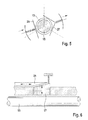
- the FIG. 3 can be seen in which the guide body 17 are each formed as a pin 24.
- FIG. 4 shows an example of an embodiment of the guide body 17 as pivotable about a pivot point D guide blocks 25 which are hinged about the pivot point D to the strand 15 and away from it.
- two guide body 17 are provided, one of which is designed as a flat guide 26 and another angle guide 27.
- the two guide bodies 17 are spring-loaded and form a three-point bearing.
- the guide body 17 is also spring-loaded and by means of a sliding element 28 on the inclined plane radially to the strand 15 and away from this adjustable.
- All guide bodies 17 of all embodiments can have a radial adjustment path, which makes it possible for the guide bodies 17 to be in the waiting or strand release position, ie to be withdrawn radially outward at a distance from the strand 15 and, secondly, in the guiding position close to or on the strand 15.
- the guide body 17 in the radially outward so far retractable in a waiting position that the diameter described by the inner sides or guide surfaces of the guide body 17 diameter F Di in the waiting position is equal to or greater than the inner diameter K Di of the strand flow channel 13 Im Operating state corresponds to the diameter F Di about the outer diameter of the strand 15th
- a measuring assembly 30 which is designed and arranged for measuring strands 15 of the tobacco processing industry and which comprises a measuring head 31 with at least one measuring station 32.
- the number of measuring stations 32 can vary. In the embodiment shown, two measuring stations 32 are provided.
- the measuring stations 32 may be, for example, optical diameter measuring means, optical strand inspection units, microwave measuring means or other common measuring systems.
- a strand passage channel 13 is formed within the measuring head 31.
- At least one strand guiding device 10 for the strand 15 to be measured is assigned to the measuring head 31.
- a strand guiding device 10 is arranged both on the input side and on the output side. According to the invention, the or each strand guiding device 10 is formed in the manner described above.
- Each measuring station 32 is usually connected to an evaluation unit 16, for example a personal computer (PC), wherein the PC can also be used as a control unit.
- This control unit can be in operative connection with the control means of the adjusting mechanism 18.
- the control units can also be combined to form a common control unit.
- Each measuring arrangement 30 can have one but also more than one strand guiding device 10.
- a single strand guiding device 10 may be arranged in the region of an inlet 20 of the measuring head 31 or in the region of an outlet 21 of the measuring head 31.
- a strand guiding device 10 can also be arranged at an arbitrary position between several measuring stations 32 of the measuring head 31 between the inlet 20 and the outlet 21.
- more than one strand guiding device 10 ie an n-fold number of strand guiding devices 10, they can be distributed over the entire length of the strand flow channel 13 from the inlet 20 to the outlet 21 as desired.
- the individual measuring stations 32 each form a type of disk-like module. This or each module may optionally be associated with a separate strand guiding device 10, which may also be a disc-like module. In further embodiments not explicitly illustrated, the or each strand guiding device 10 may also be an integral part of the measuring head 31 or of the individual measuring stations 32. In further developments of the measuring arrangement 30, the measuring head 31 can also have a plurality of preferably parallel strand passages 13. This depends, in particular, on whether the measuring arrangement 30 is part of a strand or multiple strand production machine, for example.
- the strand guiding devices 10 and / or the measuring arrangements 30 may be part of a strand manufacturing machine.
- a detailed description of such string making machines for tobacco products or filter products will be omitted, as these machines are well known in the art are known.
- Such known strand production machines are characterized according to the invention in that the or each strand guiding device 10 and / or the or each measuring arrangement 30 are formed in the manner described above. This can be achieved in a simple manner a modular design, the strand-making machine can be additionally adapted to different formats without additional effort. It is also possible to remove individual measuring heads 31 or measuring stations 32 from a strand production machine and to replace or bridge these areas released by the strand guiding devices 10 in order to achieve continuous support and guidance of the strand 15, independently of this Format.
Landscapes
- Manufacturing Of Cigar And Cigarette Tobacco (AREA)
Abstract
Description
Die Erfindung betrifft eine Strangführungsvorrichtung, ausgebildet und eingerichtet zum Führen von Strängen der Tabak verarbeitenden Industrie, umfassend ein Gehäuse mit mindestens einem durch das Gehäuse verlaufenden Strangdurchlaufkanal, wobei innerhalb des oder jedes Strangdurchlaufkanals eine Formatführung für den zu führenden Strang angeordnet ist.The invention relates to a strand guiding device, designed and arranged for guiding strands of the tobacco processing industry, comprising a housing having at least one strand passageway extending through the housing, wherein within the or each strand passage channel a format guide for the strand to be led is arranged.
Des Weiteren betrifft die Erfindung eine Messanordnung, ausgebildet und eingerichtet zum Messen von Strängen der Tabak verarbeitenden Industrie, umfassend einen Messkopf mit mindestens einer Messstation, wobei innerhalb des Messkopfes mindestens ein Strangdurchlaufkanal ausgebildet ist und dem Messkopf mindestens eine Strangführungsvorrichtung für den zu messenden Strang zugeordnet ist.Furthermore, the invention relates to a measuring arrangement, designed and adapted for measuring strands of the tobacco processing industry, comprising a measuring head with at least one measuring station, wherein within the measuring head at least one strand passage channel is formed and the measuring head is assigned at least one strand guiding device for the strand to be measured ,
Die Erfindung betrifft auch eine Strangherstellungsmaschine zum Herstellen von Strängen der Tabak verarbeitenden Industrie mit einer Strangführungsvorrichtung und/oder einer Messanordnung.The invention also relates to a strand production machine for producing strands of the tobacco processing industry with a strand guiding device and / or a measuring arrangement.
Solche Strangführungsvorrichtungen kommen in der Tabak verarbeitenden Industrie zum Einsatz, um Stränge, also endlose Stränge oder Strangabschnitte aus Tabak, Tabakmischungen, Filtermaterial oder anderen zur Herstellung von Zigaretten, Zigarillos oder dergleichen geeigneten Materialien und Materialmischungen zu führen. Üblicherweise unterliegen die Stränge und Strangabschnitte aufgrund ihrer Länge oder von außen einwirkender Belastungen z.B. durch den Transport oder durch andere Bearbeitungsvorgänge, wie z.B. den Schneidvorgängen zum Trennen der Stränge in Strangabschnitte, Schwingungen. Diese Schwingungen und/oder das Durchhängen eines schlecht geführten Strangs führen dazu, dass dieser zusätzlichen Belastungen ausgesetzt ist und insbesondere aufgrund der hohen Geschwindigkeiten, mit denen die Stränge und Strangabschnitte transportiert werden, zum Bruch neigt. Daher werden die wahlweise umhüllten oder umhüllungsfreien Stränge und Strangabschnitte kontinuierlich durch den Strangdurchlaufkanal des Gehäuses transportiert. Mittels der Formatführung werden die Stränge, Strangabschnitte oder dergleichen dabei geführt. Die Strangführungsvorrichtung umfasst üblicherweise eine Formatführung, die bekanntermaßen ein Formatteil ist, das bezüglich seines Innendurchmessers in Bezug auf den Außendurchmesser des zu transportierenden und zu führenden Strangs eng toleriert ist, so dass der im Formatteil geführte und transportierte Strang spielarm oder spielfrei in dem Formatteil liegt. Jedes üblicherweise fest eingebaute Formatteil ist jeweils für ein Format, also einen Strangdurchmesser, ausgebildet.Such strand guiding devices are used in the tobacco processing industry to guide strands, that is, endless strands or strand sections of tobacco, blends of tobacco, filter material or other materials and blends of materials suitable for making cigarettes, cigarillos or the like. Usually, the strands and strand sections are subject to vibrations due to their length or externally applied loads, for example due to transport or other machining operations, such as the cutting operations for separating the strands into strand sections. These vibrations and / or the sagging of a poorly routed strand will cause it to be subject to additional stresses and will tend to fracture, particularly due to the high speeds at which the strands and strand sections are transported. Therefore, the selectively wrapped or sheath-free strands and strand sections are continuously transported through the strand passageway of the housing. By means of the format guide the strands, strand sections or the like are guided. The strand guiding device usually comprises a format guide, which is known to be a format part which is closely tolerated with respect to its inner diameter with respect to the outer diameter of the strand to be transported and conveyed, so that the strand guided and transported in the format part lies in the format part with little play or play. Each usually permanently installed format part is in each case designed for a format, ie a strand diameter.
Das Führen der Stränge bzw. Strangabschnitte hat insbesondere in Messanordnungen der eingangs genannten Art eine große Bedeutung, da eine ungenaue Führung und das Schwingen der Stränge bzw. Strangabschnitte zu ungenauen Messergebnissen führen. Mit anderen Worten lösen die der Messstation vorgeordneten und/oder nachgeordneten Stationen zur Ausführung unterschiedlicher Bearbeitungsvorgänge sowie der Transport selbst Schwingungen auf den Strang aus, die zu einer negativen Beeinflussung der Messresultate führen. Um diese Schwingungen in ihren Ausmaßen zu begrenzen, weist die Messanordnung eine Führung auf, mittels der die Schwingungen mindestens teilweise unterdrückt werden. Genauer ist dem Messkopf eine Strangführungsvorrichtung zugeordnet, mittels der der Strang beruhigt und geführt wird. Mit einer Strangführungsvorrichtung, einer Messanordnung mit einer Strangführungsvorrichtung oder einer Strangherstellungsmaschine mit einer Strangführungsvorrichtung und/oder einer Messanordnung sollen aber Stränge bzw. Strangabschnitte unterschiedlicher Formate geführt, gemessen und hergestellt werden. Insbesondere ein Markenwechsel erfordert üblicherweise die Anpassung der Formatführung an einen geänderten Durchmesser des Strangs. In der Messanordnung können mittels der oder jeder Messstation beispielsweise die Dichte des Strangs, die Beschaffenheit und/oder Zusammensetzung des Strangs, die Umhüllung oder andere Parameter durch optische Messsysteme, mittels Infrarot-Technologie oder mittels anderer üblicher Messmethoden und Messsysteme gemessen werden. Bisher besteht die Möglichkeit, die Strangführungsvorrichtung oder die Messanordnung durch Austausch der Führungen bzw. der dem jeweiligen Strang angepassten Formatteile an das jeweilige Strangformat anzupassen. Die bisherige Lösung weist aber eine Fülle von Nachteilen auf. Zum einen ist aufwendig, die Strangführungsvorrichtungen oder Messanordnungen für unterschiedliche Formate komplett lagerhaltig vorzuhalten. Zum anderen fehlt es bei einem Formatwechsel an der Flexibilität an der Produktionsmaschine, wenn sich der Durchmesser des Strangs ändert. Des Weiteren ist die Reinigung solcher Strangführungsvorrichtungen und Messanordnungen und insbesondere der auf den engen Durchmesser der Stränge angepassten Formatteile wegen der auftretenden Engstellen schwierig. Für besondere Formate bzw. Formatvarianten müssen Formatteile individuell angefertigt werden, was einerseits die Kosten erhöht und andererseits die Durchlaufzeiten bei der Auftragsabwicklung verlängert.The guiding of the strands or strand sections is particularly important in measuring arrangements of the type mentioned at the beginning, since inaccurate guidance and the oscillation of the strands or strand sections lead to inaccurate measurement results. In other words, the stations upstream and / or downstream of the measuring station initiate vibrations on the strand for the purpose of carrying out different machining operations and the transport itself, which vibrations lead to a negative influence on the measurement results. In order to limit these vibrations in their dimensions, the measuring arrangement has a guide, by means of which the vibrations are at least partially suppressed. More precisely, a strand guiding device is associated with the measuring head, by means of which the strand is calmed and guided. With a strand guiding device, a measuring arrangement with a strand guiding device or a strand production machine with a strand guiding device and / or a measuring arrangement, however, strands or strand sections of different formats should be guided, measured and produced. In particular, a brand change usually requires the adaptation of the format guide to a changed diameter of the strand. In the measuring arrangement, for example, the density of the strand, the nature and / or composition of the strand, the envelope or other parameters can be measured by optical measuring systems, by infrared technology or by other conventional measuring methods and measuring systems by means of the or each measuring station. So far, there is the Possibility to adapt the strand guiding device or the measuring arrangement to the respective strand format by exchanging the guides or the format parts adapted to the respective strand. However, the previous solution has a wealth of disadvantages. On the one hand, it is expensive to provide the strand guiding devices or measuring arrangements for different formats completely in stock. On the other hand, a format change lacks flexibility in the production machine when the diameter of the strand changes. Furthermore, the cleaning of such strand guiding devices and measuring arrangements, and in particular the adapted to the narrow diameter of the strands format parts difficult because of the bottlenecks. For special formats or format variants format parts must be made individually, which on the one hand increases the costs and on the other hand extends the processing times in the order processing.
Das Dokument
Der Erfindung liegt damit die Aufgabe zugrunde, eine Strangführungsvorrichtung zu schaffen, die das Führen unterschiedlicher Formate auf einfache und zuverlässige Weise gewährleistet. Des Weiteren ist es Aufgabe der Erfindung, eine Messanordnung zu schaffen, mittels der unterschiedliche Formate einfach und zuverlässig überprüft werden können. Die Aufgabe besteht weiterhin darin, eine entsprechende Strangherstellungsmaschine vorzuschlagen.The invention is thus based on the object to provide a strand guiding device which ensures the guiding of different formats in a simple and reliable manner. Furthermore, it is an object of the invention to provide a measuring arrangement by means of which different formats can be checked easily and reliably. The object continues to be to propose a corresponding strand production machine.
Diese Aufgabe wird durch eine Strangführungsvorrichtung der eingangs genannten Art dadurch gelöst, dass die oder jede Formatführung als eine radial verstellbare Mehrpunktlagerung ausgebildet ist. Mit dieser erfindungsgemäßen Ausbildung ist eine formatunabhängige Strangführungsvorrichtung geschaffen, mit deren Hilfe ein so genannter "Quick-Size-Change" ermöglicht werden kann. Anders ausgedrückt ist es auf einfache und günstige Weise möglich, die Strangführungsvorrichtung an das jeweils zu führende Strangformat anzupassen. Mit anderen Worten gewährleistet die Strangführungsvorrichtung eine maximale Flexibilität bei der Anpassung der Formatführung an unterschiedliche Durchmesser der zu führenden Stränge. Eine Anpassung kann durch diese Ausbildung ohne Umbauaufwand erfolgen, was die Umrüstzeiten z.B. bei einem Markenwechsel deutlich verkürzt. Mit einer erfindungsgemäßen Formatführung ist eine individuelle und stufenlose Anpassung der Formatführung an sämtliche Durchmesser in einem definierten Bereich, für die Stränge/Strangabschnitte der Tabak verarbeitenden Industrie beispielsweise zwischen 3 und 12mm, zuverlässig sichergestellt.This object is achieved by a strand guiding device of the type mentioned above in that the or each format guide is designed as a radially adjustable multipoint bearing. With this embodiment of the invention, a format-independent strand guiding device is created, with the aid of which a so-called "quick-size change" can be made possible. In other words, it is possible in a simple and cheap way to adapt the strand guiding device to the respective strand format to be performed. In other words, the strand guiding device ensures maximum flexibility in adapting the format guide to different diameters of the strands to be led. An adaptation can be done by this training without conversion effort, which makes the changeover times, e.g. significantly shortened when changing a brand. With a format guide according to the invention an individual and continuous adjustment of the format guide to all diameters in a defined range, for the strands / strand sections of the tobacco processing industry, for example, between 3 and 12mm, reliably ensured.
Eine zweckmäßige Weiterbildung der Erfindung zeichnet sich dadurch aus, dass die oder jede Formatführung mindestens zwei am zu führenden Strang anliegende Führungskörper sowie mindestens einen Verstellmechanismus zum radialen Verstellen der Führungskörper umfasst. Mit dieser besonders einfachen Ausbildung einer verstellbaren Mehrpunktlagerung, also einer Lagerung mit zwei oder mehr Lagerpunkten, ist eine kostengünstige und zuverlässige Formatführung geschaffen. Durch den Verstellmechanismus wird erreicht, dass die Formatführung bzw. genauer die Führungskörper im Stillstand oder beim Wechsel eines Formates radial nach außen verstellbar sind, um einen größeren Durchlaufbereich zu schaffen und im Betrieb vorzugsweise automatisch radial nach innen auf den engeren Durchlaufbereich, dessen Durchmesser etwa dem Durchmesser der zu führenden Stränge entspricht, verstellbar sind. Mit dem Aufbringen der radialen Verstellbewegung der Führungskörper lässt sich ein besonders exakter Ringspalt zwischen den Führungskörpern und dem zu führenden Strang einstellen.An expedient development of the invention is characterized in that the or each format guide comprises at least two adjacent to the leading strand leading body and at least one adjusting mechanism for radially adjusting the guide body. With this particularly simple design of an adjustable Mehrpunktlagerung, so a storage with two or more storage points, a cost-effective and reliable format guide is created. The adjusting mechanism ensures that the format guide or, more precisely, the guide body can be adjusted radially outward during standstill or when changing a format, in order to provide a larger passage area and, during operation, preferably automatically radially inwards to the narrower passage area Diameter approximately equal to the diameter of the strands to be led, are adjustable. With the application of the radial adjustment movement of the guide body, a particularly accurate annular gap between the guide bodies and the leading strand can be set.
Vorteilhafterweise sind alle Führungskörper in Umfangsrichtung des zu führenden Strangs mit einem Abstand zueinander angeordnet. Mit anderen Worten wird keine ringförmige, den gesamten Umfang umschließende Führung geschaffen, sondern vielmehr eine punktuelle Führung, wodurch die Klemmgefahr reduziert ist.Advantageously, all guide bodies are arranged in the circumferential direction of the leading strand with a distance from one another. In other words, no annular, surrounding the entire circumference guide is provided, but rather a point guide, whereby the risk of clamping is reduced.
Eine besonders zweckmäßige Weiterbildung der Erfindung zeichnet sich dadurch aus, dass zwischen den den Strang führenden Führungskörpern und dem Verstellmechanismus eine starre Wirkverbindung besteht. Das bedeutet, dass die Verstellbewegung des Verstellmechanismus direkt und reproduzierbar auf die Führungskörper übertragbar ist, so dass der Mittelpunkt unabhängig von der Formatgröße stets eine identische Position aufweist, wodurch ein hohe Messgenauigkeit erreichbar ist. Damit wird weiterhin erreicht, dass der Ringspalt zwischen den Führungskörpern und dem zu führenden Strang exakt eingestellt werden kann, was zu einer weiteren Reduzierung der Klemmgefahr führt.A particularly expedient development of the invention is characterized in that there is a rigid operative connection between the guide bodies guiding the strand and the adjusting mechanism. This means that the adjusting movement of the adjusting mechanism can be transferred directly and reproducibly to the guide bodies, so that the center point always has an identical position regardless of the size of the format, as a result of which a high measuring accuracy can be achieved. This further ensures that the annular gap between the guide bodies and the leading strand can be set exactly, resulting in a further reduction of the risk of clamping.
Eine vorteilhafte Weiterbildung zeichnet sich dadurch aus, dass jede Formatführung drei gleichmäßig über den Umfang verteilte Führungskörper aufweist. Mit einer solchen Dreipunktlagerung, bei der die Führungskörper in einer Winkelanordnung um 120° versetzt angeordnet sind, wird neben der Formatflexibilität eine besonders zuverlässige Beruhigung des Stranges erreicht.An advantageous development is characterized in that each format guide has three guide bodies distributed uniformly over the circumference. With such a three-point bearing, in which the guide body are arranged offset in an angular arrangement by 120 °, in addition to the format flexibility a particularly reliable calming of the strand is achieved.
Zweckmäßigerweise ist allen Führungskörpern ein gemeinsamer Verstellmechanismus zugeordnet. Dadurch wird die Handhabung besonders vereinfacht und die Zuverlässigkeit der Führung verbessert. Insbesondere die Synchronverstellung aller Führungskörper stellt eine verkantungsfreie Verstellung und Führung des Strangs sicher.Conveniently, all the guide bodies associated with a common adjustment mechanism. As a result, the handling is particularly simplified and improves the reliability of the leadership. In particular, the synchronous adjustment of all guide body ensures a tilt-free adjustment and leadership of the strand.
Eine besonders bevorzugte Ausführungsform der Erfindung ist dadurch gekennzeichnet, dass die Führungskörper in radialer Richtung nach außen in eine Warteposition derart weit zurückziehbar sind, dass der durch die Innenseiten der Führungskörper beschriebene Durchmesser in der Warteposition gleich oder größer ist als der Innendurchmesser des Strangdurchlaufkanals. Damit ist insbesondere das Reinigen des Strangdurchlaufkanals vereinfacht. Die Zugänglichkeit in den Strangdurchlaufkanal von außen ist damit wesentlich verbessert. Des Weiteren können die in Transportrichtung hinter den Formatführungen liegenden Bereiche des Strangdurchlaufkanals ungehindert z.B. zum Zwecke der Inspektion erreicht werden.A particularly preferred embodiment of the invention is characterized in that the guide body in the radially outward direction to a waiting position are retractable so far that the diameter described by the inner sides of the guide body in the waiting position is equal to or greater than the inner diameter of the strand passage channel. This simplifies in particular the cleaning of the strand passage channel. The accessibility in the strand passage channel from the outside is thus substantially improved. Furthermore, the regions of the strand passage channel lying in the transport direction behind the format guides can be unhindered, e.g. be achieved for the purpose of inspection.
Die Aufgabe wird auch durch eine Messanordnung der eingangs genannten Art dadurch gelöst, dass die oder jede Strangführungsvorrichtung nach einem der Ansprüche 1 bis 10 ausgebildet ist. Die sich daraus ergebenden Vorteile wurden bereits im Zusammenhang mit der Strangführungsvorrichtung beschrieben, weshalb zur Vermeidung von Wiederholungen auf die entsprechenden Passagen verwiesen wird.The object is also achieved by a measuring arrangement of the type mentioned above in that the or each strand guiding device is designed according to one of claims 1 to 10. The resulting advantages have already been described in connection with the strand guiding device, so reference is made to avoid repetition on the corresponding passages.
Vorteilhafterweise ist die oder jede Strangherstellungsvorrichtung wahlweise im Bereich eines Einlaufs des Messkopfes und/oder eines Auslaufs des Messkopfes und/oder an einer beliebigen Position zwischen mehreren Messstationen des Messkopfes zwischen dem Einlauf und dem Auslauf angeordnet. In Abhängigkeit der Länge des Strangdurchlaufkanals und/oder der Position der die Schwingung auslösenden Bearbeitungsvorgänge bzw. Vorrichtungen zum Ausführen der Bearbeitungsvorgänge kann es sinnvoll sein, nur am Einlauf oder nur am Auslauf oder nur zwischen dem Einlauf und dem Auslauf oder sowohl am Einlauf als auch am Auslauf eine oder mehrere Strangführungsvorrichtungen bzw. Formatführungen vorzusehen. Aber auch andere Aspekte, beispielsweise besonders große Schwingungen, können dazu führen, anstelle einer einzelnen Strangführungsvorrichtung mehrere Strangführungsvorrichtungen vorzusehen, um eine optimale Führung und Beruhigung der Stränge sicherzustellen.Advantageously, the or each strand production device is optionally arranged in the region of an inlet of the measuring head and / or an outlet of the measuring head and / or at an arbitrary position between a plurality of measuring stations of the measuring head between the inlet and the outlet. Depending on the length of the strand passage channel and / or the position of the vibration triggering operations or devices for performing the machining operations, it may be useful only at the inlet or only at the outlet or only between the inlet and the outlet or both at the inlet and on Outlet one or more strand guide devices or format guides provide. However, other aspects, such as particularly large vibrations, may result in providing multiple strand guiding devices instead of a single strand guiding device to ensure optimum guidance and calming of the strands.
In einer bevorzugten Weiterbildung der erfindungsgemäßen Messanordnung ist die oder jede Strangführungsvorrichtung integraler Bestandteil des Messkopfes. Dadurch wird eine kompakte und als Modul einsetzbare Messanordnung geschaffen, die universell einsetzbar ist.In a preferred embodiment of the measuring arrangement according to the invention, the or each strand guiding device is an integral part of the measuring head. This will a compact and usable as a module measuring arrangement created, which is universally applicable.
Die Aufgabe wird auch durch eine Strangherstellungsmaschine zum Herstellen von Strängen der Tabak verarbeitenden Industrie mit mindestens einer Strangführungsvorrichtung nach einem der Ansprüche 1 bis 10 und/oder mit einer Messanordnung nach einem der Ansprüche 11 bis 13. Die sich daraus ergebende Vorteile wurden weiter oben bereits beschrieben.The object is also achieved by a strand manufacturing machine for producing strands of the tobacco processing industry with at least one strand guiding device according to one of claims 1 to 10 and / or with a measuring arrangement according to one of
Weitere zweckmäßige und/oder vorteilhafte Merkmale und Weiterbildungen ergeben sich aus den Unteransprüchen und der Beschreibung. Besonders bevorzugte Ausführungsformen werden anhand der beigefügten Zeichnung näher erläutert. In der Zeichnung zeigt:
- Fig. 1
- eine schematische Darstellung mehrerer Strangführungsvorrichtungen mit einem im Strangdurchlaufkanal befindlichen Strang,
- Fig. 2
- eine erste Ausführungsform einer Formatführung mit drei als Kufen ausgebildeten Führungskörpern,
- Fig. 3
- eine weitere Ausführungsform einer Formatführung,
- Fig. 4
- eine weitere Ausführungsform einer Formatführung,
- Fig. 5
- eine weitere Ausführungsform einer Formatführung,
- Fig. 6
- eine weitere Ausführungsform einer Formatführung, und
- Fig. 7
- eine schematische Darstellung einer Messanordnung mit zwei der Messanordnung zugeordneten Strangführungsvorrichtungen.
- Fig. 1
- a schematic representation of several strand guiding devices with a strand located in the strand passage,
- Fig. 2
- a first embodiment of a format guide with three runners designed as runners,
- Fig. 3
- another embodiment of a format guide,
- Fig. 4
- another embodiment of a format guide,
- Fig. 5
- another embodiment of a format guide,
- Fig. 6
- another embodiment of a format guide, and
- Fig. 7
- a schematic representation of a measuring arrangement with two of the measuring arrangement associated strand guiding devices.
Die in der Zeichnung dargestellte Strangführungsvorrichtung ist zum Führen von Strängen der Tabak verarbeitenden Industrie ausgebildet und eingerichtet. Die entsprechende Messanordnung ist zum Messen von Strängen der Tabak verarbeitenden Industrie, beispielsweise aus Tabak, ausgebildet und eingerichtet. Selbstverständlich ist sowohl die Strangführungsvorrichtung als auch die Messanordnung auch zum Führen bzw. Messen anderer Stränge oder stabförmiger Artikel geeignet.The strand guiding device shown in the drawing is designed and arranged for guiding strands of the tobacco processing industry. The corresponding measuring arrangement is designed and set up for measuring strands of the tobacco-processing industry, for example made of tobacco. Of course, both the strand guiding device and the measuring arrangement are also suitable for guiding or measuring other strands or rod-shaped articles.
Jede der in
Im Folgenden werden zweckmäßige und/oder vorteilhafte Merkmale und Ausführungsformen der erfindungsgemäßen Strangführungsvorrichtung 10 beschrieben, die jeweils alleine oder in Kombination miteinander die Erfindung weiterbilden.In the following, functional and / or advantageous features and embodiments of the
Die oder jede Formatführung 14 umfasst mindestens zwei am zu führenden Strang 15 anliegende Führungskörper 17 sowie mindestens einen Verstellmechanismus 18 zum radialen Verstellen der Führungskörper 17. Für die Führung des Strangs 15 sind zwei Führungskörper 17 ausreichend. Bevorzugt weist die Formatführung 14 jedoch drei Führungskörper 17 auf, die dann wiederum bevorzugt gleichmäßig über den Umfang, also jeweils um 120° versetzt (beispielsweise in einer Winkelanordnung von 15°/135°/255°), verteilt sind. Die Winkelanordnung kann ebenso wie die Anzahl der Führungskörper 17 variieren. Unabhängig von der Anzahl der Führungskörper 17 sind alle Führungskörper 17 in Umfangsrichtung des zu führenden Strangs 15 mit einem Abstand zueinander angeordnet. Zwischen benachbarten Führungskörpern 17 ist demnach zu beiden Seiten ein Freiraum ausgebildet. Die Führungskörper 17, die vorzugsweise aus einem nicht verformbaren Werkstoff gebildet sind, bilden im Betrieb der Strangführungsvorrichtung 10 mit ihrer dem Strang 15 zugewandten Seite/Fläche die Anlageflächen für den Strang 15, so dass dieser beruhigt und dadurch schwingungsarm in dem Strangdurchlaufkanal 13 transportierbar ist. Um aus der Führungsposition (Betriebszustand) in die Warte- oder Strangfreigabeposition (Stillstandsposition) und umgekehrt zu gelangen, ist dem oder jedem Führungskörper 17 der Verstellmechanismus 18 zugeordnet. Optional ist allen Führungskörpern 17 einer Formatführung 14 ein einzelner, gemeinsamer Verstellmechanismus 18 zugeordnet. Dieser wirkt synchron auf alle Führungskörper 17. Alternativ kann auch jeder Führungskörper 17 über seinen eigenen Verstellmechanismus 18 verfügen, wobei die Verstellmechanismen 18 dann vorzugsweise synchronisiert sind. Bevorzugt besteht zwischen den den Strang 15 führenden Führungskörpern 17 und dem Verstellmechanismus 18 eine starre Wirkverbindung.The or each
Als Verstellmechanismus 18 für die Verstellung der Führungskörper 17 kommt beispielsweise ein Drehfutter 19 in Betracht. Dieses wie ein Backen- oder Bohrfutter ausgebildete Drehfutter 19 kann mechanisch oder elektrisch betätigt bzw. angetrieben sein. Optional ist der Verstellmechanismus 18 auch an ein nicht explizit dargestelltes Steuermittel angeschlossen. Der Verstellmechanismus 18 kann optional auch aus einer Pneumatik- oder Hydraulikeinrichtung gebildet sein, bei der die Verstellung gegen eine Federkraft (siehe z.B.
Die Ausbildung der Führungskörper 17 kann ebenfalls variieren. Sie können z.B. als Stift, Bolzen, Kufe, Kugel, Winkel, Backe oder in anderer geeigneter Form ausgebildet sein. In der
Sämtliche Führungskörper 17 aller Ausführungsformen können einen radialen Verstellweg aufweisen, der es ermöglicht, dass sich die Führungskörper 17 einerseits in der Warte- oder Strangfreigabeposition befinden, also radial nach außen zurückgezogen mit einem Abstand zum Strang 15 versehen sind und sich andererseits in der Führungsposition nahe am oder am Strang 15 befinden. Besonders bevorzugt sind die Führungskörper 17 in radialer Richtung nach außen derart weit in eine Warteposition zurückziehbar, dass der durch die Innenseiten bzw. Führungsflächen der Führungskörper 17 beschriebene Durchmesser FDi in der Warteposition gleich oder größer ist als der Innendurchmesser KDi des Strangdurchlaufkanals 13. Im Betriebszustand entspricht der Durchmesser FDi etwa dem Außendurchmesser des Strangs 15.All guide
In der
Die oder jede Messstation 32 ist üblicherweise an eine Auswerteeinheit 16, beispielsweise einen Personal-Computer (PC), angeschlossen, wobei der PC auch als Steuereinheit einsetzbar ist. Diese Steuereinheit kann in Wirkverbindung mit dem Steuermittel des Verstellmechanismus 18 stehen. Die Steuereinheiten können auch zu einer gemeinsamen Steuereinheit zusammengefasst werden. Jede Messanordnung 30 kann eine aber auch mehr als eine Strangführungsvorrichtung 10 aufweisen. In einer ersten Ausführung kann eine einzelne Strangführungsvorrichtung 10 im Bereich eines Einlaufs 20 des Messkopfes 31 oder im Bereich eines Auslaufs 21 des Messkopfes 31 angeordnet sein. Eine Strangführungsvorrichtung 10 kann aber auch an einer beliebigen Position zwischen mehreren Messstationen 32 des Messkopfes 31 zwischen dem Einlauf 20 und dem Auslauf 21 angeordnet sein. Bei mehr als einer Strangführungsvorrichtung 10, also einer n-fachen Anzahl von Strangführungsvorrichtungen 10, können diese beliebig über die gesamte Länge des Strangdurchlaufkanals 13 vom Einlauf 20 bis zum Auslauf 21 verteilt sein.The or each measuring
In der Ausführungsform gemäß der
Wie weiter oben beschrieben, können die Strangführungsvorrichtungen 10 und/oder die Messanordnungen 30 Bestandteil einer Strangherstellungsmaschine sein. Von einer detaillierten Beschreibung solcher Strangherstellungsmaschinen für Tabakprodukte oder Filterprodukte wird abgesehen, da diese Maschinen im Stand der Technik hinlänglich bekannt sind. Allerdings ist es aufwendig, diese Strangherstellungsmaschinen für jeden Formatwechsel umzurüsten. Solche bekannten Strangherstellungsmaschinen zeichnen sich erfindungsgemäß dadurch aus, dass die oder jede Strangführungsvorrichtung 10 und/oder die oder jede Messanordnung 30 in der weiter oben beschriebenen Weise ausgebildet sind. Damit kann auf einfache Weise eine modulare Bauweise erreicht werden, wobei die Strangherstellungsmaschine zusätzlich ohne Mehraufwand an unterschiedliche Formate angepasst werden kann. Auch besteht die Möglichkeit, aus einer Strangherstellungsmaschine einzelne Messköpfe 31 bzw. Messstationen 32 zu entfernen und diese frei werdenden Bereiche durch die Strangführungsvorrichtungen 10 zu ersetzen bzw. zu überbrücken, um eine kontinuierliche Stützung und Führung des Stranges 15 zu erreichen, und zwar unabhängig von dessen Format.As described above, the
Claims (14)
Priority Applications (1)
| Application Number | Priority Date | Filing Date | Title |
|---|---|---|---|
| PL12163392T PL2508086T5 (en) | 2011-04-06 | 2012-04-05 | Device for conveying a rod, measuring assembly with same and rod production machine with rod conveying device and/or measuring assembly |
Applications Claiming Priority (1)
| Application Number | Priority Date | Filing Date | Title |
|---|---|---|---|
| DE102011016851A DE102011016851A1 (en) | 2011-04-06 | 2011-04-06 | Strand guiding device, measuring arrangement with such a strand guiding device and strand production machine with strand guiding device and / or measuring arrangement |
Publications (3)
| Publication Number | Publication Date |
|---|---|
| EP2508086A1 true EP2508086A1 (en) | 2012-10-10 |
| EP2508086B1 EP2508086B1 (en) | 2016-01-20 |
| EP2508086B2 EP2508086B2 (en) | 2019-10-09 |
Family
ID=46025479
Family Applications (1)
| Application Number | Title | Priority Date | Filing Date |
|---|---|---|---|
| EP12163392.9A Active EP2508086B2 (en) | 2011-04-06 | 2012-04-05 | Device for conveying a rod, measuring assembly with same and rod production machine with rod conveying device and/or measuring assembly |
Country Status (4)
| Country | Link |
|---|---|
| EP (1) | EP2508086B2 (en) |
| CN (1) | CN102726831B (en) |
| DE (1) | DE102011016851A1 (en) |
| PL (1) | PL2508086T5 (en) |
Cited By (1)
| Publication number | Priority date | Publication date | Assignee | Title |
|---|---|---|---|---|
| EP2756768B1 (en) | 2013-01-18 | 2016-01-06 | HAUNI Maschinenbau AG | Device for longitudinally conveying rod-shaped products in the tobacco processing industry |
Families Citing this family (1)
| Publication number | Priority date | Publication date | Assignee | Title |
|---|---|---|---|---|
| DE102012208450B4 (en) * | 2012-05-21 | 2015-03-26 | Hauni Maschinenbau Ag | Strand forming device and strand machine of the tobacco processing industry |
Citations (6)
| Publication number | Priority date | Publication date | Assignee | Title |
|---|---|---|---|---|
| DE1011339B (en) * | 1953-08-19 | 1957-06-27 | Molins Machine Co Ltd | Device for guiding a cigarette rod through a testing device |
| US2952262A (en) * | 1957-01-30 | 1960-09-13 | Molins Machine Co Ltd | Manufacture of cigarettes |
| DE1180662B (en) | 1958-06-16 | 1964-10-29 | Molins Machine Co Ltd | Device for guiding a cigarette rod or the like. |
| US3485144A (en) * | 1968-01-10 | 1969-12-23 | Brown & Williamson Tobacco | Garniture for continuous-rod cigarette machinery |
| GB1372056A (en) * | 1972-01-07 | 1974-10-30 | Molins Ltd | Production of cigaretes |
| EP0569817A1 (en) * | 1992-05-13 | 1993-11-18 | G.D Societa' Per Azioni | Machine for producing at least one continuous rod of smoking material |
Family Cites Families (7)
| Publication number | Priority date | Publication date | Assignee | Title |
|---|---|---|---|---|
| US4022221A (en) † | 1975-10-31 | 1977-05-10 | American Filtrona Corporation | Tobacco smoke filter |
| US4104522A (en) † | 1977-03-14 | 1978-08-01 | Measurex Corporation | Apparatus for measuring the weight per unit length of a cigarette rod |
| US4413637A (en) † | 1981-01-19 | 1983-11-08 | Philip Morris Inc. | Dynamic circumference gage |
| IT1186557B (en) * | 1985-01-23 | 1987-12-04 | Gd Spa | CONTROL AND CORRECTION DEVICE FOR THE CROSS SIZE OF BAR-SHAPED PRODUCTS, IN PARTICULAR FOR SMOKE PRODUCT PACKAGING MACHINES |
| DE3800431C2 (en) † | 1988-01-09 | 1997-06-05 | Hauni Werke Koerber & Co Kg | Device for the longitudinal axial guidance of rod-shaped articles of the tobacco processing industry |
| CN1447655A (en) † | 2000-08-17 | 2003-10-08 | 日本烟草产业株式会社 | Cigarette inspection device |
| DE102005032366A1 (en) * | 2005-07-08 | 2007-01-11 | Hauni Maschinenbau Ag | Forming device of the tobacco processing industry |
-
2011
- 2011-04-06 DE DE102011016851A patent/DE102011016851A1/en not_active Withdrawn
-
2012
- 2012-04-05 PL PL12163392T patent/PL2508086T5/en unknown
- 2012-04-05 EP EP12163392.9A patent/EP2508086B2/en active Active
- 2012-04-05 CN CN201210096993.8A patent/CN102726831B/en active Active
Patent Citations (6)
| Publication number | Priority date | Publication date | Assignee | Title |
|---|---|---|---|---|
| DE1011339B (en) * | 1953-08-19 | 1957-06-27 | Molins Machine Co Ltd | Device for guiding a cigarette rod through a testing device |
| US2952262A (en) * | 1957-01-30 | 1960-09-13 | Molins Machine Co Ltd | Manufacture of cigarettes |
| DE1180662B (en) | 1958-06-16 | 1964-10-29 | Molins Machine Co Ltd | Device for guiding a cigarette rod or the like. |
| US3485144A (en) * | 1968-01-10 | 1969-12-23 | Brown & Williamson Tobacco | Garniture for continuous-rod cigarette machinery |
| GB1372056A (en) * | 1972-01-07 | 1974-10-30 | Molins Ltd | Production of cigaretes |
| EP0569817A1 (en) * | 1992-05-13 | 1993-11-18 | G.D Societa' Per Azioni | Machine for producing at least one continuous rod of smoking material |
Cited By (2)
| Publication number | Priority date | Publication date | Assignee | Title |
|---|---|---|---|---|
| EP2756768B1 (en) | 2013-01-18 | 2016-01-06 | HAUNI Maschinenbau AG | Device for longitudinally conveying rod-shaped products in the tobacco processing industry |
| EP2756768B2 (en) † | 2013-01-18 | 2019-01-23 | Hauni Maschinenbau GmbH | Device for longitudinally conveying rod-shaped products in the tobacco processing industry |
Also Published As
| Publication number | Publication date |
|---|---|
| DE102011016851A1 (en) | 2012-10-11 |
| CN102726831A (en) | 2012-10-17 |
| CN102726831B (en) | 2016-09-21 |
| PL2508086T5 (en) | 2020-02-28 |
| EP2508086B2 (en) | 2019-10-09 |
| PL2508086T3 (en) | 2016-06-30 |
| EP2508086B1 (en) | 2016-01-20 |
Similar Documents
| Publication | Publication Date | Title |
|---|---|---|
| EP2668857B1 (en) | Transport drum for the tobacco processing industry | |
| DE102012224505A1 (en) | Apparatus and method for laterally guiding a rolled or cast product on a transport line | |
| EP3426421A1 (en) | Device for producing reinforcement cages | |
| DE4019285A1 (en) | CLAMPING DEVICE FOR TARGETED CLAMPING OF WORKPIECES | |
| EP1897453B1 (en) | Device for conveying rod-shaped articles | |
| DE3445575C2 (en) | Device for spacing and inverting two coaxial cigarette lengths in a filter assembly machine | |
| EP2508086B1 (en) | Device for conveying a rod, measuring assembly with same and rod production machine with rod conveying device and/or measuring assembly | |
| EP1425979B1 (en) | Multifunctional conveyor drum | |
| DE102011007294A1 (en) | Device for forming a dough strip from supplied dough portions | |
| EP2666372A2 (en) | Rod forming device and rod machine for the tobacco processing industry | |
| EP3042574B1 (en) | Device and method for frontal inspection of a transversally conveyed rod-shaped article in a machine for the tobacco processing industry | |
| DE102019134097A1 (en) | Conveyor drum of the tobacco processing industry | |
| DE10351068A1 (en) | staggering drum | |
| EP2371480B1 (en) | Profile processing centre | |
| DE10351070B4 (en) | staggering drum | |
| EP2074895A1 (en) | Lining device in a machine for the tobacco processing industry | |
| EP2409923A2 (en) | Clamping device | |
| DE102015001714A1 (en) | Device for the production of products of the tobacco processing industry | |
| DE602004011570T2 (en) | MULTI-STAGE UNIT FOR PROCESSING A PACKAGING MATERIAL RAILWAY | |
| EP3161197B1 (en) | Pressing device for pressing a braided tube onto a component core and braiding machine | |
| EP1447016A1 (en) | Multifunctional conveyor drum | |
| EP3369685A1 (en) | Device for transporting elongated pieces to a pick-up position and for depositing elongated pieces at this position | |
| DE102013200340B4 (en) | Profile processing device | |
| DE102012100757B3 (en) | Device for guiding and holding a continuously conveyed in the transport direction T strand of tobacco processing industry and Tubenradsatz | |
| DE3306579C2 (en) | Wire guide device, in particular for metal wire of preferably round profile |
Legal Events
| Date | Code | Title | Description |
|---|---|---|---|
| PUAI | Public reference made under article 153(3) epc to a published international application that has entered the european phase |
Free format text: ORIGINAL CODE: 0009012 |
|
| AK | Designated contracting states |
Kind code of ref document: A1 Designated state(s): AL AT BE BG CH CY CZ DE DK EE ES FI FR GB GR HR HU IE IS IT LI LT LU LV MC MK MT NL NO PL PT RO RS SE SI SK SM TR |
|
| AX | Request for extension of the european patent |
Extension state: BA ME |
|
| 17P | Request for examination filed |
Effective date: 20130408 |
|
| GRAP | Despatch of communication of intention to grant a patent |
Free format text: ORIGINAL CODE: EPIDOSNIGR1 |
|
| RIC1 | Information provided on ipc code assigned before grant |
Ipc: A24C 5/34 20060101ALI20150703BHEP Ipc: A24C 5/14 20060101AFI20150703BHEP |
|
| INTG | Intention to grant announced |
Effective date: 20150724 |
|
| GRAS | Grant fee paid |
Free format text: ORIGINAL CODE: EPIDOSNIGR3 |
|
| GRAA | (expected) grant |
Free format text: ORIGINAL CODE: 0009210 |
|
| AK | Designated contracting states |
Kind code of ref document: B1 Designated state(s): AL AT BE BG CH CY CZ DE DK EE ES FI FR GB GR HR HU IE IS IT LI LT LU LV MC MK MT NL NO PL PT RO RS SE SI SK SM TR |
|
| REG | Reference to a national code |
Ref country code: GB Ref legal event code: FG4D Free format text: NOT ENGLISH |
|
| REG | Reference to a national code |
Ref country code: CH Ref legal event code: EP |
|
| REG | Reference to a national code |
Ref country code: IE Ref legal event code: FG4D Free format text: LANGUAGE OF EP DOCUMENT: GERMAN |
|
| REG | Reference to a national code |
Ref country code: AT Ref legal event code: REF Ref document number: 771291 Country of ref document: AT Kind code of ref document: T Effective date: 20160215 |
|
| REG | Reference to a national code |
Ref country code: DE Ref legal event code: R096 Ref document number: 502012005762 Country of ref document: DE |
|
| REG | Reference to a national code |
Ref country code: NL Ref legal event code: FP |
|
| REG | Reference to a national code |
Ref country code: LT Ref legal event code: MG4D |
|
| RAP2 | Party data changed (patent owner data changed or rights of a patent transferred) |
Owner name: HAUNI MASCHINENBAU GMBH |
|
| REG | Reference to a national code |
Ref country code: DE Ref legal event code: R081 Ref document number: 502012005762 Country of ref document: DE Owner name: HAUNI MASCHINENBAU GMBH, DE Free format text: FORMER OWNER: HAUNI MASCHINENBAU AG, 21033 HAMBURG, DE |
|
| PG25 | Lapsed in a contracting state [announced via postgrant information from national office to epo] |
Ref country code: GR Free format text: LAPSE BECAUSE OF FAILURE TO SUBMIT A TRANSLATION OF THE DESCRIPTION OR TO PAY THE FEE WITHIN THE PRESCRIBED TIME-LIMIT Effective date: 20160421 Ref country code: NO Free format text: LAPSE BECAUSE OF FAILURE TO SUBMIT A TRANSLATION OF THE DESCRIPTION OR TO PAY THE FEE WITHIN THE PRESCRIBED TIME-LIMIT Effective date: 20160420 Ref country code: ES Free format text: LAPSE BECAUSE OF FAILURE TO SUBMIT A TRANSLATION OF THE DESCRIPTION OR TO PAY THE FEE WITHIN THE PRESCRIBED TIME-LIMIT Effective date: 20160120 Ref country code: FI Free format text: LAPSE BECAUSE OF FAILURE TO SUBMIT A TRANSLATION OF THE DESCRIPTION OR TO PAY THE FEE WITHIN THE PRESCRIBED TIME-LIMIT Effective date: 20160120 Ref country code: HR Free format text: LAPSE BECAUSE OF FAILURE TO SUBMIT A TRANSLATION OF THE DESCRIPTION OR TO PAY THE FEE WITHIN THE PRESCRIBED TIME-LIMIT Effective date: 20160120 |
|
| PG25 | Lapsed in a contracting state [announced via postgrant information from national office to epo] |
Ref country code: RS Free format text: LAPSE BECAUSE OF FAILURE TO SUBMIT A TRANSLATION OF THE DESCRIPTION OR TO PAY THE FEE WITHIN THE PRESCRIBED TIME-LIMIT Effective date: 20160120 Ref country code: LT Free format text: LAPSE BECAUSE OF FAILURE TO SUBMIT A TRANSLATION OF THE DESCRIPTION OR TO PAY THE FEE WITHIN THE PRESCRIBED TIME-LIMIT Effective date: 20160120 Ref country code: PT Free format text: LAPSE BECAUSE OF FAILURE TO SUBMIT A TRANSLATION OF THE DESCRIPTION OR TO PAY THE FEE WITHIN THE PRESCRIBED TIME-LIMIT Effective date: 20160520 Ref country code: LV Free format text: LAPSE BECAUSE OF FAILURE TO SUBMIT A TRANSLATION OF THE DESCRIPTION OR TO PAY THE FEE WITHIN THE PRESCRIBED TIME-LIMIT Effective date: 20160120 Ref country code: IS Free format text: LAPSE BECAUSE OF FAILURE TO SUBMIT A TRANSLATION OF THE DESCRIPTION OR TO PAY THE FEE WITHIN THE PRESCRIBED TIME-LIMIT Effective date: 20160520 Ref country code: SE Free format text: LAPSE BECAUSE OF FAILURE TO SUBMIT A TRANSLATION OF THE DESCRIPTION OR TO PAY THE FEE WITHIN THE PRESCRIBED TIME-LIMIT Effective date: 20160120 Ref country code: BE Free format text: LAPSE BECAUSE OF NON-PAYMENT OF DUE FEES Effective date: 20160430 |
|
| REG | Reference to a national code |
Ref country code: DE Ref legal event code: R026 Ref document number: 502012005762 Country of ref document: DE |
|
| PLBI | Opposition filed |
Free format text: ORIGINAL CODE: 0009260 |
|
| REG | Reference to a national code |
Ref country code: NL Ref legal event code: PD Owner name: HAUNI MASCHINENBAU GMBH; DE Free format text: DETAILS ASSIGNMENT: VERANDERING VAN EIGENAAR(S), VERANDERING VAN DE JURIDISCHE ENTITEIT; FORMER OWNER NAME: HAUNI MASCHINENBAU AG Effective date: 20160928 |
|
| PG25 | Lapsed in a contracting state [announced via postgrant information from national office to epo] |
Ref country code: DK Free format text: LAPSE BECAUSE OF FAILURE TO SUBMIT A TRANSLATION OF THE DESCRIPTION OR TO PAY THE FEE WITHIN THE PRESCRIBED TIME-LIMIT Effective date: 20160120 Ref country code: EE Free format text: LAPSE BECAUSE OF FAILURE TO SUBMIT A TRANSLATION OF THE DESCRIPTION OR TO PAY THE FEE WITHIN THE PRESCRIBED TIME-LIMIT Effective date: 20160120 |
|
| 26 | Opposition filed |
Opponent name: G.D S.P.A. Effective date: 20161019 |
|
| PLAX | Notice of opposition and request to file observation + time limit sent |
Free format text: ORIGINAL CODE: EPIDOSNOBS2 |
|
| PG25 | Lapsed in a contracting state [announced via postgrant information from national office to epo] |
Ref country code: CZ Free format text: LAPSE BECAUSE OF FAILURE TO SUBMIT A TRANSLATION OF THE DESCRIPTION OR TO PAY THE FEE WITHIN THE PRESCRIBED TIME-LIMIT Effective date: 20160120 Ref country code: RO Free format text: LAPSE BECAUSE OF FAILURE TO SUBMIT A TRANSLATION OF THE DESCRIPTION OR TO PAY THE FEE WITHIN THE PRESCRIBED TIME-LIMIT Effective date: 20160120 Ref country code: SK Free format text: LAPSE BECAUSE OF FAILURE TO SUBMIT A TRANSLATION OF THE DESCRIPTION OR TO PAY THE FEE WITHIN THE PRESCRIBED TIME-LIMIT Effective date: 20160120 Ref country code: SM Free format text: LAPSE BECAUSE OF FAILURE TO SUBMIT A TRANSLATION OF THE DESCRIPTION OR TO PAY THE FEE WITHIN THE PRESCRIBED TIME-LIMIT Effective date: 20160120 |
|
| REG | Reference to a national code |
Ref country code: CH Ref legal event code: PL |
|
| PG25 | Lapsed in a contracting state [announced via postgrant information from national office to epo] |
Ref country code: LU Free format text: LAPSE BECAUSE OF FAILURE TO SUBMIT A TRANSLATION OF THE DESCRIPTION OR TO PAY THE FEE WITHIN THE PRESCRIBED TIME-LIMIT Effective date: 20160405 |
|
| REG | Reference to a national code |
Ref country code: IE Ref legal event code: MM4A |
|
| REG | Reference to a national code |
Ref country code: FR Ref legal event code: ST Effective date: 20161230 |
|
| PG25 | Lapsed in a contracting state [announced via postgrant information from national office to epo] |
Ref country code: LI Free format text: LAPSE BECAUSE OF NON-PAYMENT OF DUE FEES Effective date: 20160430 Ref country code: FR Free format text: LAPSE BECAUSE OF NON-PAYMENT OF DUE FEES Effective date: 20160502 Ref country code: CH Free format text: LAPSE BECAUSE OF NON-PAYMENT OF DUE FEES Effective date: 20160430 |
|
| PG25 | Lapsed in a contracting state [announced via postgrant information from national office to epo] |
Ref country code: BG Free format text: LAPSE BECAUSE OF FAILURE TO SUBMIT A TRANSLATION OF THE DESCRIPTION OR TO PAY THE FEE WITHIN THE PRESCRIBED TIME-LIMIT Effective date: 20160420 Ref country code: SI Free format text: LAPSE BECAUSE OF FAILURE TO SUBMIT A TRANSLATION OF THE DESCRIPTION OR TO PAY THE FEE WITHIN THE PRESCRIBED TIME-LIMIT Effective date: 20160120 |
|
| PLBB | Reply of patent proprietor to notice(s) of opposition received |
Free format text: ORIGINAL CODE: EPIDOSNOBS3 |
|
| PG25 | Lapsed in a contracting state [announced via postgrant information from national office to epo] |
Ref country code: IE Free format text: LAPSE BECAUSE OF NON-PAYMENT OF DUE FEES Effective date: 20160405 |
|
| PG25 | Lapsed in a contracting state [announced via postgrant information from national office to epo] |
Ref country code: HU Free format text: LAPSE BECAUSE OF FAILURE TO SUBMIT A TRANSLATION OF THE DESCRIPTION OR TO PAY THE FEE WITHIN THE PRESCRIBED TIME-LIMIT; INVALID AB INITIO Effective date: 20120405 Ref country code: CY Free format text: LAPSE BECAUSE OF FAILURE TO SUBMIT A TRANSLATION OF THE DESCRIPTION OR TO PAY THE FEE WITHIN THE PRESCRIBED TIME-LIMIT Effective date: 20160120 |
|
| REG | Reference to a national code |
Ref country code: AT Ref legal event code: MM01 Ref document number: 771291 Country of ref document: AT Kind code of ref document: T Effective date: 20170405 |
|
| PG25 | Lapsed in a contracting state [announced via postgrant information from national office to epo] |
Ref country code: MT Free format text: LAPSE BECAUSE OF FAILURE TO SUBMIT A TRANSLATION OF THE DESCRIPTION OR TO PAY THE FEE WITHIN THE PRESCRIBED TIME-LIMIT Effective date: 20160120 Ref country code: MC Free format text: LAPSE BECAUSE OF FAILURE TO SUBMIT A TRANSLATION OF THE DESCRIPTION OR TO PAY THE FEE WITHIN THE PRESCRIBED TIME-LIMIT Effective date: 20160120 Ref country code: TR Free format text: LAPSE BECAUSE OF FAILURE TO SUBMIT A TRANSLATION OF THE DESCRIPTION OR TO PAY THE FEE WITHIN THE PRESCRIBED TIME-LIMIT Effective date: 20160120 Ref country code: MK Free format text: LAPSE BECAUSE OF FAILURE TO SUBMIT A TRANSLATION OF THE DESCRIPTION OR TO PAY THE FEE WITHIN THE PRESCRIBED TIME-LIMIT Effective date: 20160120 |
|
| PG25 | Lapsed in a contracting state [announced via postgrant information from national office to epo] |
Ref country code: AT Free format text: LAPSE BECAUSE OF NON-PAYMENT OF DUE FEES Effective date: 20170405 |
|
| PG25 | Lapsed in a contracting state [announced via postgrant information from national office to epo] |
Ref country code: AL Free format text: LAPSE BECAUSE OF FAILURE TO SUBMIT A TRANSLATION OF THE DESCRIPTION OR TO PAY THE FEE WITHIN THE PRESCRIBED TIME-LIMIT Effective date: 20160120 |
|
| PUAH | Patent maintained in amended form |
Free format text: ORIGINAL CODE: 0009272 |
|
| STAA | Information on the status of an ep patent application or granted ep patent |
Free format text: STATUS: PATENT MAINTAINED AS AMENDED |
|
| 27A | Patent maintained in amended form |
Effective date: 20191009 |
|
| AK | Designated contracting states |
Kind code of ref document: B2 Designated state(s): AL AT BE BG CH CY CZ DE DK EE ES FI FR GB GR HR HU IE IS IT LI LT LU LV MC MK MT NL NO PL PT RO RS SE SI SK SM TR |
|
| REG | Reference to a national code |
Ref country code: DE Ref legal event code: R102 Ref document number: 502012005762 Country of ref document: DE |
|
| REG | Reference to a national code |
Ref country code: NL Ref legal event code: FP |
|
| REG | Reference to a national code |
Ref country code: DE Ref legal event code: R081 Ref document number: 502012005762 Country of ref document: DE Owner name: KOERBER TECHNOLOGIES GMBH, DE Free format text: FORMER OWNER: HAUNI MASCHINENBAU GMBH, 21033 HAMBURG, DE |
|
| REG | Reference to a national code |
Ref country code: NL Ref legal event code: HC Owner name: KOERBER TECHNOLOGIES GMBH; DE Free format text: DETAILS ASSIGNMENT: CHANGE OF OWNER(S), CHANGE OF OWNER(S) NAME; FORMER OWNER NAME: HAUNI MASCHINENBAU GMBH Effective date: 20221020 |
|
| P01 | Opt-out of the competence of the unified patent court (upc) registered |
Effective date: 20230621 |
|
| PGFP | Annual fee paid to national office [announced via postgrant information from national office to epo] |
Ref country code: NL Payment date: 20240425 Year of fee payment: 13 |
|
| PGFP | Annual fee paid to national office [announced via postgrant information from national office to epo] |
Ref country code: PL Payment date: 20240322 Year of fee payment: 13 |
|
| PGFP | Annual fee paid to national office [announced via postgrant information from national office to epo] |
Ref country code: GB Payment date: 20240423 Year of fee payment: 13 |
|
| PGFP | Annual fee paid to national office [announced via postgrant information from national office to epo] |
Ref country code: DE Payment date: 20240425 Year of fee payment: 13 |
|
| PGFP | Annual fee paid to national office [announced via postgrant information from national office to epo] |
Ref country code: IT Payment date: 20240426 Year of fee payment: 13 |